EP4300739A2 - System including connector bracket - Google Patents
System including connector bracket Download PDFInfo
- Publication number
- EP4300739A2 EP4300739A2 EP23181545.7A EP23181545A EP4300739A2 EP 4300739 A2 EP4300739 A2 EP 4300739A2 EP 23181545 A EP23181545 A EP 23181545A EP 4300739 A2 EP4300739 A2 EP 4300739A2
- Authority
- EP
- European Patent Office
- Prior art keywords
- planar surface
- cable
- planar
- connector
- holes
- Prior art date
- Legal status (The legal status is an assumption and is not a legal conclusion. Google has not performed a legal analysis and makes no representation as to the accuracy of the status listed.)
- Pending
Links
- 238000000034 method Methods 0.000 description 5
- 239000002184 metal Substances 0.000 description 4
- 238000004519 manufacturing process Methods 0.000 description 3
- 230000008901 benefit Effects 0.000 description 2
- 238000012508 change request Methods 0.000 description 2
- 238000013459 approach Methods 0.000 description 1
- 230000000712 assembly Effects 0.000 description 1
- 238000000429 assembly Methods 0.000 description 1
- 238000010276 construction Methods 0.000 description 1
- 238000009434 installation Methods 0.000 description 1
- 230000002452 interceptive effect Effects 0.000 description 1
- 239000000463 material Substances 0.000 description 1
- 238000004806 packaging method and process Methods 0.000 description 1
Images





Classifications
-
- H—ELECTRICITY
- H02—GENERATION; CONVERSION OR DISTRIBUTION OF ELECTRIC POWER
- H02G—INSTALLATION OF ELECTRIC CABLES OR LINES, OR OF COMBINED OPTICAL AND ELECTRIC CABLES OR LINES
- H02G3/00—Installations of electric cables or lines or protective tubing therefor in or on buildings, equivalent structures or vehicles
- H02G3/30—Installations of cables or lines on walls, floors or ceilings
- H02G3/32—Installations of cables or lines on walls, floors or ceilings using mounting clamps
-
- B—PERFORMING OPERATIONS; TRANSPORTING
- B60—VEHICLES IN GENERAL
- B60R—VEHICLES, VEHICLE FITTINGS, OR VEHICLE PARTS, NOT OTHERWISE PROVIDED FOR
- B60R16/00—Electric or fluid circuits specially adapted for vehicles and not otherwise provided for; Arrangement of elements of electric or fluid circuits specially adapted for vehicles and not otherwise provided for
- B60R16/02—Electric or fluid circuits specially adapted for vehicles and not otherwise provided for; Arrangement of elements of electric or fluid circuits specially adapted for vehicles and not otherwise provided for electric constitutive elements
- B60R16/0207—Wire harnesses
- B60R16/0215—Protecting, fastening and routing means therefor
-
- H—ELECTRICITY
- H01—ELECTRIC ELEMENTS
- H01R—ELECTRICALLY-CONDUCTIVE CONNECTIONS; STRUCTURAL ASSOCIATIONS OF A PLURALITY OF MUTUALLY-INSULATED ELECTRICAL CONNECTING ELEMENTS; COUPLING DEVICES; CURRENT COLLECTORS
- H01R13/00—Details of coupling devices of the kinds covered by groups H01R12/70 or H01R24/00 - H01R33/00
- H01R13/73—Means for mounting coupling parts to apparatus or structures, e.g. to a wall
-
- F—MECHANICAL ENGINEERING; LIGHTING; HEATING; WEAPONS; BLASTING
- F16—ENGINEERING ELEMENTS AND UNITS; GENERAL MEASURES FOR PRODUCING AND MAINTAINING EFFECTIVE FUNCTIONING OF MACHINES OR INSTALLATIONS; THERMAL INSULATION IN GENERAL
- F16B—DEVICES FOR FASTENING OR SECURING CONSTRUCTIONAL ELEMENTS OR MACHINE PARTS TOGETHER, e.g. NAILS, BOLTS, CIRCLIPS, CLAMPS, CLIPS OR WEDGES; JOINTS OR JOINTING
- F16B2/00—Friction-grip releasable fastenings
- F16B2/02—Clamps, i.e. with gripping action effected by positive means other than the inherent resistance to deformation of the material of the fastening
- F16B2/06—Clamps, i.e. with gripping action effected by positive means other than the inherent resistance to deformation of the material of the fastening external, i.e. with contracting action
- F16B2/08—Clamps, i.e. with gripping action effected by positive means other than the inherent resistance to deformation of the material of the fastening external, i.e. with contracting action using bands
Definitions
- inventions of the inventive concepts disclosed herein are directed to a system.
- the system includes a connector bracket.
- the connector bracket includes a first planar plate section defined by a top first planar surface, a bottom first planar surface, and first side edges, wherein the first planar plate section includes first holes extending between the top first planar surface and the bottom first planar surface.
- the connector bracket includes a second planar plate section defined by a top second planar surface, a bottom second planar surface, and second side edges, wherein the second planar plate section includes second holes extending between the top second planar surface and the bottom second planar surface.
- the connector bracket includes a groove section connected between the first planar plate section and the second planar plate section, wherein the groove section is defined by a groove that drops below the top first planar surface and the top second planar surface.
- the top first planar surface is coplanar with the top second planar surface.
- inventive concepts are not limited in their application to the details of construction and the arrangement of the components or steps or methodologies set forth in the following description or illustrated in the drawings.
- inventive concepts disclosed herein may be practiced without these specific details.
- well-known features may not be described in detail to avoid unnecessarily complicating the instant disclosure.
- inventive concepts disclosed herein are capable of other embodiments or of being practiced or carried out in various ways. Also, it is to be understood that the phraseology and terminology employed herein is for the purpose of description and should not be regarded as limiting.
- a letter following a reference numeral is intended to reference an embodiment of the feature or element that may be similar, but not necessarily identical, to a previously described element or feature bearing the same reference numeral (e.g., 1, 1a, 1b).
- reference numeral e.g. 1, 1a, 1b
- Such shorthand notations are used for purposes of convenience only, and should not be construed to limit the inventive concepts disclosed herein in any way unless expressly stated to the contrary.
- any reference to "one embodiment,” or “some embodiments” means that a particular element, feature, structure, or characteristic described in connection with the embodiment is included in at least one embodiment of the inventive concepts disclosed herein.
- the appearances of the phrase “in some embodiments” in various places in the specification are not necessarily all referring to the same embodiment, and embodiments of the inventive concepts disclosed may include one or more of the features expressly described or inherently present herein, or any combination of sub-combination of two or more such features, along with any other features which may not necessarily be expressly described or inherently present in the instant disclosure.
- embodiments of the inventive concepts disclosed herein are directed to a system including a connector bracket.
- the connector bracket is composed of plastic.
- the connector bracket can retain connectors, and the connector bracket can be tied via at least one cable tie to a seat structure (e.g., a cable raceway) and/or cables (e.g., cable bundles) (tied on top of cable bundles) using cable ties.
- the connector bracket may include holes (e.g., oblong slots) that can be used to hold the connectors with cable ties.
- the connector bracket may include a groove section including a groove, whereby the groove can accommodate a cable tie that can secure the connector bracket to a structural part of the seat and/or cables. The connector bracket can make it simple to package connectors anywhere in a seat frame assembly.
- the connector bracket is light in weight and will not add more than negligible weight to the seat.
- the connector brackets can greatly reduce an amount of engineering hours needed to package connectors in seats as the bracket connector allows the connectors to be placed at many more potential locations in the seat.
- the connector brackets can reduce the occurrence of rejections by original equipment manufacturers (OEMs) and vendors and can reduce the occurrence of engineers and manufacturing teams having to rework electrical routings to accommodate connectors.
- the connector brackets can avoid the occurrence of change requests and checks performed after rework following the change requests.
- the connector bracket may reduce engineering and manufacturing costs for electrical routing.
- the connector bracket may be easy and inexpensive to manufacture and may only need a single die to make, and the connector bracket can be used on all seating products, as well as on non-seating applications.
- the installation of the connector brackets may be easy, such as by using cable ties, and connectors can be easily clipped or unclipped during service.
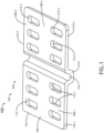
- FIG. 1 a top perspective view of an exemplary embodiment of a system 100 including a vehicle (e.g., aircraft 102, watercraft, automobile, train, etc.) including at least one connector bracket 104 is depicted according to the inventive concepts.
- the connector bracket may be installed within a seat frame assembly (e.g., 402; e.g., aircraft seat frame assembly); in other embodiments, the connector bracket 104 can be used for non-vehicular and/or non-seat applications and environments.
- the connector bracket 104 may be made of any suitable material, such as plastic or rubber-coated metal.
- the connector bracket 104 may include a first planar plate section 106-1 defined by a top first planar surface 108-1, a bottom first planar surface 118-1 (as shown in FIG. 3 ), and first side edges 110-1.
- the first planar plate section 106-1 may include any number (e.g., 2, 3, 4, 5, 6, or more) of first holes 112-1 (e.g., round holes, square holes, rectangular holes, and/or oblong slots) extending between the top first planar surface 108-1 and the bottom first planar surface 118-1.
- the connector bracket 104 may include a second planar plate section 106-2 defined by a top second planar surface 108-2, a bottom second planar surface 118-2 (as shown in FIG. 3 ), and second side edges 110-2.
- the second planar plate section 106-2 may include any number (e.g., 2, 3, 4, 5, 6, or more) of second holes 112-2 (e.g., round holes, square holes, rectangular holes, and/or oblong slots) extending between the top second planar surface 108-2 and the bottom second planar surface 118-2.
- the top first planar surface 108-1 may be coplanar with the top second planar surface 108-2.
- the first planar plate section 106-1 may be symmetric to the second planar plate section 106-2.
- the connector bracket 104 may include a groove section 114.
- the groove section 114 may be connected between the first planar plate section 106-1 and the second planar plate section 106-2.
- the groove section may be defined by a groove 116 that drops below the top first planar surface 108-1 and the top second planar surface 108-2.
- the groove section 114 may be defined by a groove 116 that drops below the top first planar surface 108-1, the top second planar surface 108-2, the bottom first planar surface 118-1, and the bottom second planar surface 118-2.
- each of the top first planar surface 108-1, the top second planar surface 108-2, the bottom first planar surface 118-1, and the bottom second planar surface 118-2 is rectangular or rectangular with at least one rounded corner.
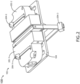
- the system 100 may include the vehicle (e.g., aircraft 102, watercraft, automobile, train, etc.) including the at least one connector bracket 104, at least one connector 202-1, 202-2, and at least one cable tie 204-1, 204-2, 204-3.
- FIG. 2 shows a top perspective view of the at least one connector bracket 104, at least one connector 202-1, 202-2, and at least one cable tie 204-1, 204-2, 204-3.
- FIG. 3 shows a bottom perspective view of the at least one connector bracket 104, at least one connector 202-1, 202-2, and at least one cable tie 204-1, 204-2, 204-3.
- the system 100 may include a first cable connector 202-1, a first cable tie 204-1, a second cable connector 202-2, and optionally a second cable tie 204-2.
- the first cable connector 202-1 may be secured against the top first planar surface 108-1 by the first cable tie 204-1.
- the first cable tie 204-1 may pass through two or more of the first holes 112-1.
- the second cable connector 202-2 may be secured against the top second planar surface 108-2 by the second cable tie 204-2 (if present).
- the second cable tie 204-2 (if present) passes through two or more of the second holes 112-2.
- the second cable connector 202-2 may be secured against the top second planar surface 108-2 by being connected to the first cable connector 202-1.
- first connector 202-1 and the second connector 202-2 may be connected to each other.
- the system 100 may include a third cable tie 204-3 and at least one object (e.g., at least one of a cable raceway 404 or at least one cable 406, as shown in FIG. 4 et seq.).
- the connector bracket 104 may be secured to the at least one object by the third cable tie 204-3.
- a portion of the third cable tie 204-3 may reside in the groove 116 of the groove section 114 and may wrap around the at least one object.
- the third cable tie 204-3 may reside in the groove 116 such that the third cable tie 204-3 is in between a bottom of the groove 116 and the top planar surfaces 108-1, 108-2 such that the third cable tie 204-3 does not interfere with the connectors 202-1, 202-2.
- the system 100 may include the vehicle (e.g., aircraft 102, watercraft, automobile, train, etc.) including at least one seat frame assembly 402 (e.g., a vehicle seat frame assembly, such as an aircraft seat frame assembly) including the at least one connector bracket 104, at least one connector 202-1, 202-2, at least one cable tie 204-1, 204-2, and/or 204-3, at least one cable raceway 404 (e.g., at least on seat cable raceway), and/or at least one cable 406 (e.g., at least one cable bundle).
- vehicle e.g., aircraft 102, watercraft, automobile, train, etc.
- vehicle e.g., aircraft 102, watercraft, automobile, train, etc.
- the vehicle e.g., aircraft 102, watercraft, automobile, train, etc.
- at least one seat frame assembly 402 e.g., a vehicle seat frame assembly, such as an aircraft seat frame assembly
- the at least one connector bracket 104 e.g.,
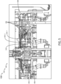
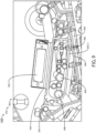
- FIGS. 4-5 show top views of exemplary embodiments including the seat frame assembly 402 including the connector bracket 104, the connectors 202-1, 202-2, cable ties 204-1, 204-2, and/or 204-3, a cable raceway 404, and cables 406.
- FIG. 6 shows a cross-sectional view of an exemplary embodiment including the seat frame assembly 402 including the connector bracket 104, the connector 202-2, cable ties 204-2 and 204-3, the cable raceway 404, and the cables 406.
- FIG. 7 shows a top view of an exemplary embodiment including the seat frame assembly 402 including the connector bracket 104, the connectors 202-1, 202-2, cable ties 204-2 and 204-3, the cable raceway 404, the cables 406, and connector cables 702-1, 702-2.
- the connector cables 702-1, 702-2 may be connected to the connectors 202-1, 202-2.
- FIGS. 8-9 shows a cross-sectional view of an exemplary embodiment including the seat frame assembly 402 including the connector bracket 104, the connector 202-1, cable tie 204-3, the cable raceway 404, and the cables 406.
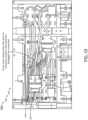
- FIGS. 10-11 shows a top view and a cross-sectional view of an exemplary embodiment including the seat frame assembly 402 including the connector bracket 104, the connectors 202-1, 202-2, cable ties 204-2 and 204-3, the cable raceway 404, the cables 406, and connector cables 702-1, 702-2.
- the connector bracket 104 may be installed in such a way that there is sufficient clearance to disconnect the connector 202-1 and disengage the connector to the side without interfering with the cables 406.
- embodiments of the inventive concepts disclosed herein may be directed to a system including a connector bracket.
- At least one means one or a plurality of; for example, “at least one” may comprise one, two, three, ..., one hundred, or more.
- one or more means one or a plurality of; for example, “one or more” may comprise one, two, three, ..., one hundred, or more.
- zero or more means zero, one, or a plurality of; for example, “zero or more” may comprise zero, one, two, three, ..., one hundred, or more.
- the methods, operations, and/or functionality disclosed may be implemented as sets of instructions or software readable by a device. Further, it is understood that the specific order or hierarchy of steps in the methods, operations, and/or functionality disclosed are examples of exemplary approaches. Based upon design preferences, it is understood that the specific order or hierarchy of steps in the methods, operations, and/or functionality can be rearranged while remaining within the scope of the inventive concepts disclosed herein.
- the accompanying claims may present elements of the various steps in a sample order, and are not necessarily meant to be limited to the specific order or hierarchy presented.
- embodiments of the methods according to the inventive concepts disclosed herein may include one or more of the steps described herein. Further, such steps may be carried out in any desired order and two or more of the steps may be carried out simultaneously with one another. Two or more of the steps disclosed herein may be combined in a single step, and in some embodiments, one or more of the steps may be carried out as two or more sub-steps. Further, other steps or sub-steps may be carried in addition to, or as substitutes to one or more of the steps disclosed herein.
- inventive concepts disclosed herein are well adapted to carry out the objects and to attain the advantages mentioned herein as well as those inherent in the inventive concepts disclosed herein. While presently preferred embodiments of the inventive concepts disclosed herein have been described for purposes of this disclosure, it will be understood that numerous changes may be made which will readily suggest themselves to those skilled in the art and which are accomplished within the broad scope and coverage of the inventive concepts disclosed and claimed herein.
Landscapes
- Engineering & Computer Science (AREA)
- Architecture (AREA)
- Civil Engineering (AREA)
- Structural Engineering (AREA)
- Mechanical Engineering (AREA)
- Connector Housings Or Holding Contact Members (AREA)
Abstract
Description
- The present application is related to and claims priority from:
Indian Application Serial Number 202241037963, titled SYSTEM INCLUDING CONNECTOR BRACKET, filed July 1, 2022 - Currently, it is difficult to package many metal connectors in aircraft seat assemblies while routing cables to and around the metal connectors. It is a challenge for engineers and assembly lines to route cables while maintaining a required distance from the connectors so as to prevent cables from chafing against the metal connectors. Additionally, it can be difficult to connect and/or disconnect connectors for service. Because of these challenges, engineers spend significant time packaging connectors and routing cables according to standards. These challenges are further exacerbated for electrical routings for seats with limited space for electrical routings, such as in economy, premium economy, business class, and first-class seats.
- In one aspect, embodiments of the inventive concepts disclosed herein are directed to a system. The system includes a connector bracket. The connector bracket includes a first planar plate section defined by a top first planar surface, a bottom first planar surface, and first side edges, wherein the first planar plate section includes first holes extending between the top first planar surface and the bottom first planar surface. The connector bracket includes a second planar plate section defined by a top second planar surface, a bottom second planar surface, and second side edges, wherein the second planar plate section includes second holes extending between the top second planar surface and the bottom second planar surface. The connector bracket includes a groove section connected between the first planar plate section and the second planar plate section, wherein the groove section is defined by a groove that drops below the top first planar surface and the top second planar surface. The top first planar surface is coplanar with the top second planar surface.
- Implementations of the inventive concepts disclosed herein may be better understood when consideration is given to the following detailed description thereof. Such description makes reference to the included drawings, which are not necessarily to scale, and in which some features may be exaggerated and some features may be omitted or may be represented schematically in the interest of clarity. Like reference numerals in the drawings may represent and refer to the same or similar element, feature, or function. In the drawings:
-
FIG. 1 is a top perspective view of an exemplary embodiment of a system including a vehicle including a connector bracket according to the inventive concepts disclosed herein. -
FIG. 2 is a top perspective view of an exemplary embodiment of the system ofFIG. 1 including the connector bracket, connectors, and cable ties according to the inventive concepts disclosed herein. -
FIG. 3 is a bottom perspective view of an exemplary embodiment of the system ofFIG. 2 according to the inventive concepts disclosed herein. -
FIG. 4 is a top view of an exemplary embodiment of the system ofFIG. 1 including the vehicle, a seat frame assembly, a cable raceway, cables, the connector bracket, the connectors, and the cable ties according to the inventive concepts disclosed herein. -
FIG. 5 is a top view of an exemplary embodiment of the system ofFIG. 1 including the vehicle, a seat frame assembly, a cable raceway, cables, the connector bracket, the connectors, and the cable ties according to the inventive concepts disclosed herein. -
FIG. 6 is a cross-sectional view of an exemplary embodiment of the system ofFIG. 1 including the vehicle, a seat frame assembly, a cable raceway, cables, the connector bracket, the connectors, and the cable ties according to the inventive concepts disclosed herein. -
FIG. 7 is a top view of an exemplary embodiment of the system ofFIG. 1 including the vehicle, a seat frame assembly, a cable raceway, cables, the connector bracket, the connectors, and the cable ties according to the inventive concepts disclosed herein. -
FIG. 8 is a cross-sectional view of an exemplary embodiment of the system ofFIG. 1 including the vehicle, a seat frame assembly, a cable raceway, cables, the connector bracket, the connectors, and the cable ties according to the inventive concepts disclosed herein. -
FIG. 9 is a cross-sectional view of an exemplary embodiment of the system ofFIG. 1 including the vehicle, a seat frame assembly, a cable raceway, cables, the connector bracket, the connectors, and the cable ties according to the inventive concepts disclosed herein. -
FIG. 10 is a top view of an exemplary embodiment of the system ofFIG. 1 including the vehicle, a seat frame assembly, a cable raceway, cables, the connector bracket, the connectors, and the cable ties according to the inventive concepts disclosed herein. -
FIG. 11 is a cross-sectional view of the system ofFIG. 10 according to the inventive concepts disclosed herein. - Before explaining at least one embodiment of the inventive concepts disclosed herein in detail, it is to be understood that the inventive concepts are not limited in their application to the details of construction and the arrangement of the components or steps or methodologies set forth in the following description or illustrated in the drawings. In the following detailed description of embodiments of the instant inventive concepts, numerous specific details are set forth in order to provide a more thorough understanding of the inventive concepts. However, it will be apparent to one of ordinary skill in the art having the benefit of the instant disclosure that the inventive concepts disclosed herein may be practiced without these specific details. In other instances, well-known features may not be described in detail to avoid unnecessarily complicating the instant disclosure. The inventive concepts disclosed herein are capable of other embodiments or of being practiced or carried out in various ways. Also, it is to be understood that the phraseology and terminology employed herein is for the purpose of description and should not be regarded as limiting.
- As used herein a letter following a reference numeral is intended to reference an embodiment of the feature or element that may be similar, but not necessarily identical, to a previously described element or feature bearing the same reference numeral (e.g., 1, 1a, 1b). Such shorthand notations are used for purposes of convenience only, and should not be construed to limit the inventive concepts disclosed herein in any way unless expressly stated to the contrary.
- Further, unless expressly stated to the contrary, "or" refers to an inclusive or and not to an exclusive or. For example, a condition A or B is satisfied by anyone of the following: A is true (or present) and B is false (or not present), A is false (or not present) and B is true (or present), and both A and B are true (or present).
- In addition, use of the "a" or "an" are employed to describe elements and components of embodiments of the instant inventive concepts. This is done merely for convenience and to give a general sense of the inventive concepts, and "a" and "an" are intended to include one or at least one and the singular also includes the plural unless it is obvious that it is meant otherwise.
- Finally, as used herein any reference to "one embodiment," or "some embodiments" means that a particular element, feature, structure, or characteristic described in connection with the embodiment is included in at least one embodiment of the inventive concepts disclosed herein. The appearances of the phrase "in some embodiments" in various places in the specification are not necessarily all referring to the same embodiment, and embodiments of the inventive concepts disclosed may include one or more of the features expressly described or inherently present herein, or any combination of sub-combination of two or more such features, along with any other features which may not necessarily be expressly described or inherently present in the instant disclosure.
- Broadly, embodiments of the inventive concepts disclosed herein are directed to a system including a connector bracket.
- In some embodiments, the connector bracket is composed of plastic. In some embodiments, the connector bracket can retain connectors, and the connector bracket can be tied via at least one cable tie to a seat structure (e.g., a cable raceway) and/or cables (e.g., cable bundles) (tied on top of cable bundles) using cable ties. In some embodiments, the connector bracket may include holes (e.g., oblong slots) that can be used to hold the connectors with cable ties. In some embodiments, the connector bracket may include a groove section including a groove, whereby the groove can accommodate a cable tie that can secure the connector bracket to a structural part of the seat and/or cables. The connector bracket can make it simple to package connectors anywhere in a seat frame assembly.
- In some embodiments, the connector bracket is light in weight and will not add more than negligible weight to the seat. The connector brackets can greatly reduce an amount of engineering hours needed to package connectors in seats as the bracket connector allows the connectors to be placed at many more potential locations in the seat. The connector brackets can reduce the occurrence of rejections by original equipment manufacturers (OEMs) and vendors and can reduce the occurrence of engineers and manufacturing teams having to rework electrical routings to accommodate connectors. The connector brackets can avoid the occurrence of change requests and checks performed after rework following the change requests. The connector bracket may reduce engineering and manufacturing costs for electrical routing. The connector bracket may be easy and inexpensive to manufacture and may only need a single die to make, and the connector bracket can be used on all seating products, as well as on non-seating applications. The installation of the connector brackets may be easy, such as by using cable ties, and connectors can be easily clipped or unclipped during service.
- Referring now to
FIG. 1 , a top perspective view of an exemplary embodiment of asystem 100 including a vehicle (e.g.,aircraft 102, watercraft, automobile, train, etc.) including at least oneconnector bracket 104 is depicted according to the inventive concepts. In some embodiments, the connector bracket may be installed within a seat frame assembly (e.g., 402; e.g., aircraft seat frame assembly); in other embodiments, theconnector bracket 104 can be used for non-vehicular and/or non-seat applications and environments. - The
connector bracket 104 may be made of any suitable material, such as plastic or rubber-coated metal. - The
connector bracket 104 may include a first planar plate section 106-1 defined by a top first planar surface 108-1, a bottom first planar surface 118-1 (as shown inFIG. 3 ), and first side edges 110-1. The first planar plate section 106-1 may include any number (e.g., 2, 3, 4, 5, 6, or more) of first holes 112-1 (e.g., round holes, square holes, rectangular holes, and/or oblong slots) extending between the top first planar surface 108-1 and the bottom first planar surface 118-1. - The
connector bracket 104 may include a second planar plate section 106-2 defined by a top second planar surface 108-2, a bottom second planar surface 118-2 (as shown inFIG. 3 ), and second side edges 110-2. The second planar plate section 106-2 may include any number (e.g., 2, 3, 4, 5, 6, or more) of second holes 112-2 (e.g., round holes, square holes, rectangular holes, and/or oblong slots) extending between the top second planar surface 108-2 and the bottom second planar surface 118-2. The top first planar surface 108-1 may be coplanar with the top second planar surface 108-2. The first planar plate section 106-1 may be symmetric to the second planar plate section 106-2. - The
connector bracket 104 may include agroove section 114. Thegroove section 114 may be connected between the first planar plate section 106-1 and the second planar plate section 106-2. The groove section may be defined by agroove 116 that drops below the top first planar surface 108-1 and the top second planar surface 108-2. In some embodiments, thegroove section 114 may be defined by agroove 116 that drops below the top first planar surface 108-1, the top second planar surface 108-2, the bottom first planar surface 118-1, and the bottom second planar surface 118-2. - In some embodiments, each of the top first planar surface 108-1, the top second planar surface 108-2, the bottom first planar surface 118-1, and the bottom second planar surface 118-2 is rectangular or rectangular with at least one rounded corner.
- Referring now to
FIGS. 2-3 , an exemplary embodiment of thesystem 100 ofFIG. 1 is shown according to the inventive concepts. Thesystem 100 may include the vehicle (e.g.,aircraft 102, watercraft, automobile, train, etc.) including the at least oneconnector bracket 104, at least one connector 202-1, 202-2, and at least one cable tie 204-1, 204-2, 204-3.FIG. 2 shows a top perspective view of the at least oneconnector bracket 104, at least one connector 202-1, 202-2, and at least one cable tie 204-1, 204-2, 204-3.FIG. 3 shows a bottom perspective view of the at least oneconnector bracket 104, at least one connector 202-1, 202-2, and at least one cable tie 204-1, 204-2, 204-3. - In some embodiments, the
system 100 may include a first cable connector 202-1, a first cable tie 204-1, a second cable connector 202-2, and optionally a second cable tie 204-2. The first cable connector 202-1 may be secured against the top first planar surface 108-1 by the first cable tie 204-1. The first cable tie 204-1 may pass through two or more of the first holes 112-1. Optionally, the second cable connector 202-2 may be secured against the top second planar surface 108-2 by the second cable tie 204-2 (if present). Optionally, the second cable tie 204-2 (if present) passes through two or more of the second holes 112-2. In some embodiments, the second cable connector 202-2 may be secured against the top second planar surface 108-2 by being connected to the first cable connector 202-1. - In some embodiments, the first connector 202-1 and the second connector 202-2 may be connected to each other.
- In some embodiments, the
system 100 may include a third cable tie 204-3 and at least one object (e.g., at least one of acable raceway 404 or at least onecable 406, as shown inFIG. 4 et seq.). Theconnector bracket 104 may be secured to the at least one object by the third cable tie 204-3. A portion of the third cable tie 204-3 may reside in thegroove 116 of thegroove section 114 and may wrap around the at least one object. In some embodiments, the third cable tie 204-3 may reside in thegroove 116 such that the third cable tie 204-3 is in between a bottom of thegroove 116 and the top planar surfaces 108-1, 108-2 such that the third cable tie 204-3 does not interfere with the connectors 202-1, 202-2. - Referring generally now to
FIGS. 4-11 , exemplary embodiments of thesystem 100 ofFIGS. 1-3 is shown according to the inventive concepts. Thesystem 100 may include the vehicle (e.g.,aircraft 102, watercraft, automobile, train, etc.) including at least one seat frame assembly 402 (e.g., a vehicle seat frame assembly, such as an aircraft seat frame assembly) including the at least oneconnector bracket 104, at least one connector 202-1, 202-2, at least one cable tie 204-1, 204-2, and/or 204-3, at least one cable raceway 404 (e.g., at least on seat cable raceway), and/or at least one cable 406 (e.g., at least one cable bundle). -
FIGS. 4-5 show top views of exemplary embodiments including theseat frame assembly 402 including theconnector bracket 104, the connectors 202-1, 202-2, cable ties 204-1, 204-2, and/or 204-3, acable raceway 404, andcables 406. -
FIG. 6 shows a cross-sectional view of an exemplary embodiment including theseat frame assembly 402 including theconnector bracket 104, the connector 202-2, cable ties 204-2 and 204-3, thecable raceway 404, and thecables 406. -
FIG. 7 shows a top view of an exemplary embodiment including theseat frame assembly 402 including theconnector bracket 104, the connectors 202-1, 202-2, cable ties 204-2 and 204-3, thecable raceway 404, thecables 406, and connector cables 702-1, 702-2. The connector cables 702-1, 702-2 may be connected to the connectors 202-1, 202-2. -
FIGS. 8-9 shows a cross-sectional view of an exemplary embodiment including theseat frame assembly 402 including theconnector bracket 104, the connector 202-1, cable tie 204-3, thecable raceway 404, and thecables 406. -
FIGS. 10-11 shows a top view and a cross-sectional view of an exemplary embodiment including theseat frame assembly 402 including theconnector bracket 104, the connectors 202-1, 202-2, cable ties 204-2 and 204-3, thecable raceway 404, thecables 406, and connector cables 702-1, 702-2. As shown, theconnector bracket 104 may be installed in such a way that there is sufficient clearance to disconnect the connector 202-1 and disengage the connector to the side without interfering with thecables 406. - As will be appreciated from the above, embodiments of the inventive concepts disclosed herein may be directed to a system including a connector bracket.
- As used throughout, "at least one" means one or a plurality of; for example, "at least one" may comprise one, two, three, ..., one hundred, or more. Similarly, as used throughout, "one or more" means one or a plurality of; for example, "one or more" may comprise one, two, three, ..., one hundred, or more. Further, as used throughout, "zero or more" means zero, one, or a plurality of; for example, "zero or more" may comprise zero, one, two, three, ..., one hundred, or more.
- In the present disclosure, the methods, operations, and/or functionality disclosed may be implemented as sets of instructions or software readable by a device. Further, it is understood that the specific order or hierarchy of steps in the methods, operations, and/or functionality disclosed are examples of exemplary approaches. Based upon design preferences, it is understood that the specific order or hierarchy of steps in the methods, operations, and/or functionality can be rearranged while remaining within the scope of the inventive concepts disclosed herein. The accompanying claims may present elements of the various steps in a sample order, and are not necessarily meant to be limited to the specific order or hierarchy presented.
- It is to be understood that embodiments of the methods according to the inventive concepts disclosed herein may include one or more of the steps described herein. Further, such steps may be carried out in any desired order and two or more of the steps may be carried out simultaneously with one another. Two or more of the steps disclosed herein may be combined in a single step, and in some embodiments, one or more of the steps may be carried out as two or more sub-steps. Further, other steps or sub-steps may be carried in addition to, or as substitutes to one or more of the steps disclosed herein.
- From the above description, it is clear that the inventive concepts disclosed herein are well adapted to carry out the objects and to attain the advantages mentioned herein as well as those inherent in the inventive concepts disclosed herein. While presently preferred embodiments of the inventive concepts disclosed herein have been described for purposes of this disclosure, it will be understood that numerous changes may be made which will readily suggest themselves to those skilled in the art and which are accomplished within the broad scope and coverage of the inventive concepts disclosed and claimed herein.
Claims (15)
- A system, comprising:
a connector bracket (104), comprising:a first planar plate section (106-1) defined by a top first planar surface (108-1), a bottom first planar surface (118-1), and first side edges (110-1), wherein the first planar plate section includes first holes (112-1) extending between the top first planar surface (108-1) and the bottom first planar surface (118-1);a second planar plate section (106-2) defined by a top second planar surface (108-2), a bottom second planar surface (118-2), and second side edges (110-2), wherein the second planar plate section includes second holes (112-2) extending between the top second planar surface (108-2) and the bottom second planar surface (118-2); anda groove section (114), the groove section connected between the first planar plate section (106-1) and the second planar plate section (106-2), wherein the groove section (114) is defined by a groove (116) that drops below the top first planar surface and the top second planar surface,wherein the top first planar surface (108-1) is coplanar with the top second planar surface (108-2). - The system of claim 1, wherein the first planar plate section (106-1) is symmetric to the second planar plate section (106-2).
- The system of claim 2, wherein the groove section (114) is defined by a groove (116) that drops below the top first planar surface, the top second planar surface, the bottom first planar surface, and the bottom second planar surface.
- The system of claim 3, wherein at least one of the first holes (112-1) and at least one of the second holes (112-2) are oblong slots.
- The system of claim 4, wherein there are at least four first holes and at least four second holes.
- The system of claim 5, wherein each of the top first planar surface (108-1), the top second planar surface (108-2), the bottom first planar surface (118-1), and the bottom second planar surface (118-2) is rectangular or rectangular with at least one rounded corner.
- The system of any preceding claim, further comprising a first cable connector (202-1), a first cable tie (204-1), a second cable connector (202-2), and optionally a second cable tie (204-2), wherein the first cable connector (202-1) is secured against the top first planar surface (108-1) by the first cable tie (204-1), wherein the first cable tie (204-1) passes through two of the first holes (112-1), wherein optionally the second cable connector (202-2) is secured against the top second planar surface (108-2) by the second cable tie (204-2), wherein optionally the second cable tie (204-2) passes through two of the second holes (112-2).
- The system of claim 7, wherein the first connector and the second connector are connected to each other.
- The system of claim 8, further comprising a third cable tie (204-3) and at least one object, wherein the connector bracket is secured to the at least one object by the third cable tie, wherein a portion of the third cable tie resides in the groove of the groove section and wraps around the at least one object.
- The system of claim 9, wherein the at least one object comprises at least one of a cable raceway (404) or at least one cable (406).
- The system of claim 10, wherein the at least one object comprises the cable raceway (404).
- The system of claim 10, wherein the at least one object comprises the at least one cable.
- The system of claim 10, wherein the at least one object comprises the cable raceway and the least one cable (406).
- The system of claim 10, further comprising a seat frame assembly (402) comprising the cable raceway (404) and the at least one cable (406), wherein the cable raceway (404) is a seat cable raceway.
- The system of claim 14, wherein the seat frame assembly (402) is a vehicle seat frame assembly, and preferably wherein the seat frame assembly (402) is an aircraft seat frame assembly, and preferably wherein the first planar plate section (106-1) is symmetric to the second planar plate section (106-2), and preferably wherein the groove section (114) is defined by a groove (116) that drops below the top first planar surface (108-1), the top second planar surface (108-2), the bottom first planar surface (118-1), and the bottom second planar surface (118-2), and more preferably wherein at least one of the first holes (112-1) and at least one of the second holes (112-2) are oblong slots, and more preferably wherein there are at least four first holes and at least four second holes.
Applications Claiming Priority (2)
| Application Number | Priority Date | Filing Date | Title |
|---|---|---|---|
| IN202241037963 | 2022-07-01 | ||
| US18/135,375 US12548945B2 (en) | 2022-07-01 | 2023-04-17 | System including connector bracket |
Publications (2)
| Publication Number | Publication Date |
|---|---|
| EP4300739A2 true EP4300739A2 (en) | 2024-01-03 |
| EP4300739A3 EP4300739A3 (en) | 2024-02-14 |
Family
ID=87047546
Family Applications (1)
| Application Number | Title | Priority Date | Filing Date |
|---|---|---|---|
| EP23181545.7A Pending EP4300739A3 (en) | 2022-07-01 | 2023-06-26 | System including connector bracket |
Country Status (1)
| Country | Link |
|---|---|
| EP (1) | EP4300739A3 (en) |
Family Cites Families (3)
| Publication number | Priority date | Publication date | Assignee | Title |
|---|---|---|---|---|
| JP5096305B2 (en) * | 2008-12-19 | 2012-12-12 | オーム電機株式会社 | Connector fixture |
| JP2019153508A (en) * | 2018-03-05 | 2019-09-12 | いすゞ自動車株式会社 | Connector fixing structure and bracket |
| ES2918981T3 (en) * | 2018-03-16 | 2022-07-21 | Niedax Gmbh & Co Kg | Cable guide connector and method for connecting cable guide elements |
-
2023
- 2023-06-26 EP EP23181545.7A patent/EP4300739A3/en active Pending
Also Published As
| Publication number | Publication date |
|---|---|
| EP4300739A3 (en) | 2024-02-14 |
Similar Documents
| Publication | Publication Date | Title |
|---|---|---|
| US7083437B2 (en) | Aircraft seat electrical quick disconnect | |
| US6619588B2 (en) | Installation of single passenger interface unit and method thereof | |
| US7687721B2 (en) | Multi-layered electrical flat strip conductor | |
| US12548945B2 (en) | System including connector bracket | |
| JP6490624B2 (en) | Wire harness | |
| US9598028B2 (en) | Raceway for fastening, guiding and/or protecting electric cable means | |
| US11437793B2 (en) | Splice member for a cable tray | |
| US20090282655A1 (en) | Connector assembly for attaching a threaded fastener to a slotted surface | |
| US6629676B1 (en) | Cable support with integral box-shaped mounting assembly | |
| US7404658B1 (en) | Light bar snap bracket assembly | |
| US20130169041A1 (en) | Wire harness system in hybrid electric vehicle | |
| EP3706272B1 (en) | Bracket for cable management | |
| CN105857631B (en) | Wire support member for environmental control system | |
| JPWO2017222075A1 (en) | Circuit body for vehicle | |
| US20030106964A1 (en) | Replacement cover having integrated data ports for power port assembly on commercial aircraft | |
| AU2005228208B2 (en) | Adjustable length cabling systems | |
| JP6423389B2 (en) | Wire harness | |
| US10023316B2 (en) | Mobile seat systems that utilize seat tracks | |
| US8070097B2 (en) | Mobile divider for an aircraft | |
| EP3901036A1 (en) | Aircraft seat bottom cushion assembly with power providing device | |
| CN113394615B (en) | Kitchen plug-in power connector assembly with spring assembly | |
| US20140138116A1 (en) | Adjustable Length Cabling Systems | |
| WO2016121479A1 (en) | Wire harness routing structure | |
| US11148618B2 (en) | Vehicle seat complete wire harness with optimized harness routing | |
| EP2637271A1 (en) | Cable mounting device and method of mounting cables |
Legal Events
| Date | Code | Title | Description |
|---|---|---|---|
| PUAI | Public reference made under article 153(3) epc to a published international application that has entered the european phase |
Free format text: ORIGINAL CODE: 0009012 |
|
| STAA | Information on the status of an ep patent application or granted ep patent |
Free format text: STATUS: THE APPLICATION HAS BEEN PUBLISHED |
|
| AK | Designated contracting states |
Kind code of ref document: A2 Designated state(s): AL AT BE BG CH CY CZ DE DK EE ES FI FR GB GR HR HU IE IS IT LI LT LU LV MC ME MK MT NL NO PL PT RO RS SE SI SK SM TR |
|
| PUAL | Search report despatched |
Free format text: ORIGINAL CODE: 0009013 |
|
| AK | Designated contracting states |
Kind code of ref document: A3 Designated state(s): AL AT BE BG CH CY CZ DE DK EE ES FI FR GB GR HR HU IE IS IT LI LT LU LV MC ME MK MT NL NO PL PT RO RS SE SI SK SM TR |
|
| RIC1 | Information provided on ipc code assigned before grant |
Ipc: H01R 13/73 20060101ALI20240109BHEP Ipc: F16B 2/08 20060101ALI20240109BHEP Ipc: B60R 16/02 20060101ALI20240109BHEP Ipc: H02G 3/32 20060101AFI20240109BHEP |
|
| STAA | Information on the status of an ep patent application or granted ep patent |
Free format text: STATUS: REQUEST FOR EXAMINATION WAS MADE |
|
| 17P | Request for examination filed |
Effective date: 20240226 |
|
| RBV | Designated contracting states (corrected) |
Designated state(s): AL AT BE BG CH CY CZ DE DK EE ES FI FR GB GR HR HU IE IS IT LI LT LU LV MC ME MK MT NL NO PL PT RO RS SE SI SK SM TR |