EP4300728A1 - Fiber laser - Google Patents
Fiber laser Download PDFInfo
- Publication number
- EP4300728A1 EP4300728A1 EP21928062.5A EP21928062A EP4300728A1 EP 4300728 A1 EP4300728 A1 EP 4300728A1 EP 21928062 A EP21928062 A EP 21928062A EP 4300728 A1 EP4300728 A1 EP 4300728A1
- Authority
- EP
- European Patent Office
- Prior art keywords
- pumping light
- forward pumping
- absorption amount
- fiber
- wavelength
- Prior art date
- Legal status (The legal status is an assumption and is not a legal conclusion. Google has not performed a legal analysis and makes no representation as to the accuracy of the status listed.)
- Pending
Links
Images


Classifications
-
- H—ELECTRICITY
- H01—ELECTRIC ELEMENTS
- H01S—DEVICES USING THE PROCESS OF LIGHT AMPLIFICATION BY STIMULATED EMISSION OF RADIATION [LASER] TO AMPLIFY OR GENERATE LIGHT; DEVICES USING STIMULATED EMISSION OF ELECTROMAGNETIC RADIATION IN WAVE RANGES OTHER THAN OPTICAL
- H01S3/00—Lasers, i.e. devices using stimulated emission of electromagnetic radiation in the infrared, visible or ultraviolet wave range
- H01S3/09—Processes or apparatus for excitation, e.g. pumping
- H01S3/091—Processes or apparatus for excitation, e.g. pumping using optical pumping
- H01S3/094—Processes or apparatus for excitation, e.g. pumping using optical pumping by coherent light
- H01S3/094003—Processes or apparatus for excitation, e.g. pumping using optical pumping by coherent light the pumped medium being a fibre
- H01S3/094011—Processes or apparatus for excitation, e.g. pumping using optical pumping by coherent light the pumped medium being a fibre with bidirectional pumping, i.e. with injection of the pump light from both two ends of the fibre
-
- H—ELECTRICITY
- H01—ELECTRIC ELEMENTS
- H01S—DEVICES USING THE PROCESS OF LIGHT AMPLIFICATION BY STIMULATED EMISSION OF RADIATION [LASER] TO AMPLIFY OR GENERATE LIGHT; DEVICES USING STIMULATED EMISSION OF ELECTROMAGNETIC RADIATION IN WAVE RANGES OTHER THAN OPTICAL
- H01S3/00—Lasers, i.e. devices using stimulated emission of electromagnetic radiation in the infrared, visible or ultraviolet wave range
- H01S3/05—Construction or shape of optical resonators; Accommodation of active medium therein; Shape of active medium
- H01S3/06—Construction or shape of active medium
- H01S3/063—Waveguide lasers, i.e. whereby the dimensions of the waveguide are of the order of the light wavelength
- H01S3/067—Fibre lasers
- H01S3/06708—Constructional details of the fibre, e.g. compositions, cross-section, shape or tapering
- H01S3/06716—Fibre compositions or doping with active elements
-
- H—ELECTRICITY
- H01—ELECTRIC ELEMENTS
- H01S—DEVICES USING THE PROCESS OF LIGHT AMPLIFICATION BY STIMULATED EMISSION OF RADIATION [LASER] TO AMPLIFY OR GENERATE LIGHT; DEVICES USING STIMULATED EMISSION OF ELECTROMAGNETIC RADIATION IN WAVE RANGES OTHER THAN OPTICAL
- H01S3/00—Lasers, i.e. devices using stimulated emission of electromagnetic radiation in the infrared, visible or ultraviolet wave range
- H01S3/05—Construction or shape of optical resonators; Accommodation of active medium therein; Shape of active medium
- H01S3/06—Construction or shape of active medium
- H01S3/063—Waveguide lasers, i.e. whereby the dimensions of the waveguide are of the order of the light wavelength
- H01S3/067—Fibre lasers
- H01S3/0675—Resonators including a grating structure, e.g. distributed Bragg reflectors [DBR] or distributed feedback [DFB] fibre lasers
-
- H—ELECTRICITY
- H01—ELECTRIC ELEMENTS
- H01S—DEVICES USING THE PROCESS OF LIGHT AMPLIFICATION BY STIMULATED EMISSION OF RADIATION [LASER] TO AMPLIFY OR GENERATE LIGHT; DEVICES USING STIMULATED EMISSION OF ELECTROMAGNETIC RADIATION IN WAVE RANGES OTHER THAN OPTICAL
- H01S3/00—Lasers, i.e. devices using stimulated emission of electromagnetic radiation in the infrared, visible or ultraviolet wave range
- H01S3/05—Construction or shape of optical resonators; Accommodation of active medium therein; Shape of active medium
- H01S3/08—Construction or shape of optical resonators or components thereof
- H01S3/08018—Mode suppression
- H01S3/0804—Transverse or lateral modes
-
- H—ELECTRICITY
- H01—ELECTRIC ELEMENTS
- H01S—DEVICES USING THE PROCESS OF LIGHT AMPLIFICATION BY STIMULATED EMISSION OF RADIATION [LASER] TO AMPLIFY OR GENERATE LIGHT; DEVICES USING STIMULATED EMISSION OF ELECTROMAGNETIC RADIATION IN WAVE RANGES OTHER THAN OPTICAL
- H01S3/00—Lasers, i.e. devices using stimulated emission of electromagnetic radiation in the infrared, visible or ultraviolet wave range
- H01S3/09—Processes or apparatus for excitation, e.g. pumping
- H01S3/091—Processes or apparatus for excitation, e.g. pumping using optical pumping
- H01S3/094—Processes or apparatus for excitation, e.g. pumping using optical pumping by coherent light
- H01S3/0941—Processes or apparatus for excitation, e.g. pumping using optical pumping by coherent light of a laser diode
- H01S3/09415—Processes or apparatus for excitation, e.g. pumping using optical pumping by coherent light of a laser diode the pumping beam being parallel to the lasing mode of the pumped medium, e.g. end-pumping
-
- H—ELECTRICITY
- H01—ELECTRIC ELEMENTS
- H01S—DEVICES USING THE PROCESS OF LIGHT AMPLIFICATION BY STIMULATED EMISSION OF RADIATION [LASER] TO AMPLIFY OR GENERATE LIGHT; DEVICES USING STIMULATED EMISSION OF ELECTROMAGNETIC RADIATION IN WAVE RANGES OTHER THAN OPTICAL
- H01S3/00—Lasers, i.e. devices using stimulated emission of electromagnetic radiation in the infrared, visible or ultraviolet wave range
- H01S3/14—Lasers, i.e. devices using stimulated emission of electromagnetic radiation in the infrared, visible or ultraviolet wave range characterised by the material used as the active medium
- H01S3/16—Solid materials
- H01S3/1601—Solid materials characterised by an active (lasing) ion
- H01S3/1603—Solid materials characterised by an active (lasing) ion rare earth
- H01S3/1618—Solid materials characterised by an active (lasing) ion rare earth ytterbium
-
- H—ELECTRICITY
- H01—ELECTRIC ELEMENTS
- H01S—DEVICES USING THE PROCESS OF LIGHT AMPLIFICATION BY STIMULATED EMISSION OF RADIATION [LASER] TO AMPLIFY OR GENERATE LIGHT; DEVICES USING STIMULATED EMISSION OF ELECTROMAGNETIC RADIATION IN WAVE RANGES OTHER THAN OPTICAL
- H01S3/00—Lasers, i.e. devices using stimulated emission of electromagnetic radiation in the infrared, visible or ultraviolet wave range
- H01S3/05—Construction or shape of optical resonators; Accommodation of active medium therein; Shape of active medium
- H01S3/06—Construction or shape of active medium
- H01S3/063—Waveguide lasers, i.e. whereby the dimensions of the waveguide are of the order of the light wavelength
- H01S3/067—Fibre lasers
- H01S3/06708—Constructional details of the fibre, e.g. compositions, cross-section, shape or tapering
- H01S3/06729—Peculiar transverse fibre profile
-
- H—ELECTRICITY
- H01—ELECTRIC ELEMENTS
- H01S—DEVICES USING THE PROCESS OF LIGHT AMPLIFICATION BY STIMULATED EMISSION OF RADIATION [LASER] TO AMPLIFY OR GENERATE LIGHT; DEVICES USING STIMULATED EMISSION OF ELECTROMAGNETIC RADIATION IN WAVE RANGES OTHER THAN OPTICAL
- H01S3/00—Lasers, i.e. devices using stimulated emission of electromagnetic radiation in the infrared, visible or ultraviolet wave range
- H01S3/09—Processes or apparatus for excitation, e.g. pumping
- H01S3/091—Processes or apparatus for excitation, e.g. pumping using optical pumping
- H01S3/094—Processes or apparatus for excitation, e.g. pumping using optical pumping by coherent light
- H01S3/094003—Processes or apparatus for excitation, e.g. pumping using optical pumping by coherent light the pumped medium being a fibre
- H01S3/094007—Cladding pumping, i.e. pump light propagating in a clad surrounding the active core
-
- H—ELECTRICITY
- H01—ELECTRIC ELEMENTS
- H01S—DEVICES USING THE PROCESS OF LIGHT AMPLIFICATION BY STIMULATED EMISSION OF RADIATION [LASER] TO AMPLIFY OR GENERATE LIGHT; DEVICES USING STIMULATED EMISSION OF ELECTROMAGNETIC RADIATION IN WAVE RANGES OTHER THAN OPTICAL
- H01S3/00—Lasers, i.e. devices using stimulated emission of electromagnetic radiation in the infrared, visible or ultraviolet wave range
- H01S3/09—Processes or apparatus for excitation, e.g. pumping
- H01S3/091—Processes or apparatus for excitation, e.g. pumping using optical pumping
- H01S3/094—Processes or apparatus for excitation, e.g. pumping using optical pumping by coherent light
- H01S3/09408—Pump redundancy
Definitions
- the present invention relates to a fiber laser including a gain fiber having a core doped with Yb.
- Fiber lasers each including, as a gain fiber, a double cladding fiber having a core doped with ytterbium (Yb) are widely used.
- Primary absorption bands of Yb in glass are a 915-nm band and a 976-nm band.
- such fiber lasers each has a configuration in which pumping light belonging to the 915-nm band or 976-nm band is supplied to the cladding of the gain fiber, to excite Yb with which the core is doped (to cause transition to the population inversion state).
- the power of pumping light may be increased and the concentration of Yb may be increased, so as to achieve sufficient amplification in the gain fiber.
- Non-patent Literature 1 C. Jauregui et al., "Physical origin of mode instabilities in high-power fiber laser systems", Opt. Express 20(12) 12912-12925 (2012 )
- a mechanism by which beam output power decreases when the TMI occurs can be explained as follows. That is, inter-mode interference between the fundamental mode and the higher order mode guided through the core occurs; this causes the signal light amount to spatially vary along the longitudinal direction of the gain fiber. This makes the induced emitted amount spatially vary along the longitudinal direction of the gain fiber, so that the amount of heat generation due to quantum defect spatially varies along the longitudinal direction of the gain fiber. As a result, the temperature spatially varies along the longitudinal direction of the gain fiber, so that the refractive index spatially varies along the longitudinal direction of the gain fiber. This variation in refractive index facilitates the transition from the fundamental mode to the higher order mode, so that the abovementioned decrease in beam output power occurs.
- one option is to increase the length of the gain fiber.
- the increase in the length of the gain fiber may give rise to another problem that stimulated Raman scattering, which causes a failure of the pumping light source, may be likely to occur.
- An aspect of the present invention has been made in view of such circumstances, and an object of the aspect is to realize a fiber laser which reduces the probability of a decrease in beam output power due to the TMI and also reduces the probability of occurrence of stimulated Raman scattering.
- a fiber laser in accordance with an aspect of the present invention employs a configuration in which the fiber laser including: a gain fiber having a core doped with Yb; and a forward pumping light source group capable of generating forward pumping light that is capable of being inputted into the gain fiber and that belongs to a 976-nm band, wherein an absorption amount of the forward pumping light in a section of the gain fiber, the section having a length of 1 m and including an end face on which the forward pumping light is incident, is not less than 253 W and not more than 1100 W as calculated according to ⁇ P( ⁇ )A( ⁇ )d ⁇ .
- P( ⁇ ) [W] is a power spectrum of the forward pumping light
- A( ⁇ ) [%/m] is an absorption rate spectrum of Yb with which the core of the gain fiber is doped.
- a fiber laser in accordance with another aspect of the present invention employs a configuration in which the fiber laser including: a gain fiber having a core doped with Yb; and a forward pumping light source group capable of generating forward pumping light that is capable of being inputted into the gain fiber and that belongs to a 976-nm band, wherein an absorption amount of the forward pumping light in a section of the gain fiber, the section having a length of 1 m and including an end face on which the forward pumping light is incident, is not less than 253 W and not more than 1100 W, when the absorption amount of the forward pumping light in the section is an actually measured value of the absorption amount of the forward pumping light.
- a fiber laser which reduces the probability of a decrease in beam output power due to the TMI and also reduces the probability of occurrence of stimulated Raman scattering.
- Fig. 1 is a block diagram illustrating the configuration of the fiber laser 1.
- the fiber laser 1 includes a gain fiber 11, a high-reflective mirror 12, a low-reflective mirror 13, a forward pumping combiner 14a, a backward pumping combiner 14b, a forward pumping light source group 15a, a backward pumping light source group 15b, an input fiber 16a, and an output fiber 16b.
- the gain fiber 11 is an optical fiber that has a function of amplifying laser light with use of energy of pumping light.
- the gain fiber 11 used is an Yb-doped double cladding fiber, which is an optical fiber that has a columnar core doped with ytterbium (Yb), a tubular inner cladding surrounding the core, and a tubular outer cladding surrounding the inner cladding.
- the cross-sectional shape of the inner cladding may be polygonal, or may be D-shaped. This enables efficient absorption of pumping light without decreasing the absorption rate of the pumping light, even in a case in which the gain fiber 11 is long.
- the distribution of refractive index of the gain fiber 11 is set so that the gain fiber 11 propagates one fundamental mode and at least one higher order mode.
- the gain fiber 11 includes no fusion-spliced point, and has a constant refractive index distribution and a constant Yb concentration throughout its length. This configuration enables elimination of connection loss, so that it is possible to reduce the total loss occurring in the gain fiber 11.
- the high-reflective mirror 12 is connected (by fusion splicing, in the present embodiment).
- the low-reflective mirror 13 is connected (by fusion splicing, in the present embodiment).
- FBGs fiber Bragg gratings
- the gain fiber 11, the high-reflective mirror 12, and the low-reflective mirror 13 constitute a resonator O that recursively amplifies laser light with wavelength ⁇ that belongs to the overlap between the two reflection wavelength bands.
- the reflectance of the low-reflective mirror 13 e.g., not more than 15%
- that of the high-reflective mirror 12 e.g., not less than 95%).
- the forward pumping light source group 15a includes ma pumping light source or sources ( ma is any natural number). Each pumping light source included in the forward pumping light source group 15a is configured to generate pumping light that belongs to the 976-nm band. As used herein, the 976-nm band refers to a wavelength band of not less than 967.9 nm and not more than 983.0 nm, in which the absorption band of Yb is included.
- the forward pumping combiner 14a is configured to input, into the gain fiber 11, pumping light generated by the respective pumping light sources included in the forward pumping light source group 15a.
- the forward pumping combiner 14a includes at least ma pumping light input port or ports 14a1, at least one visible light input port 14a2, and at least one resonator-side port 14a3. Every pumping light input port 14a1 is connected to the corresponding pumping light source constituting the forward pumping light source group 15a.
- the visible light input port 14a2 is connected to the input fiber 16a (by fusion splicing, in the present embodiment), and is for use in visual observation of the irradiation positions of laser light.
- the input of visible light into the visible light input port 14a2 is not essential, and the visible light input port 14a2 may be used as a port for inputting pumping light, or alternatively, may be used as a port for monitoring the amount of light reflected in a workpiece.
- the resonator-side port 14a3 is connected (by fusion splicing, in the present embodiment) to an end of the high-reflective mirror 12 on a side opposite to the gain fiber 11 side.
- Forward pumping light generated in each pumping light source of the forward pumping light source group 15a is guided through the forward pumping combiner 14a and the high-reflective mirror 12 to the cladding of the gain fiber 11, in which the forward pumping light is used to cause transition of the state of Yb, with which the core of the gain fiber 11 is doped, to the population inversion state.
- spontaneous emission light waves generated in the gain fiber 11 a light wave with wavelength ⁇ that matches the reflection wavelengths of the high-reflective mirror 12 and the low-reflective mirror 13 is amplified by the resonator O in the core of the gain fiber 11.
- Each LD chip is designed to have the oscillation wavelength band with a central wavelength of about 975 nm (absorption wavelength of Yb) and with a wavelength width of not less than 7 nm and not more than 12 nm.
- Fig. 1 depicts six LD modules constituting the forward pumping light source group 15a. Pumping light waves emitted from 13 LD chips, not illustrated, per LD module are coupled to a single optical fiber. That is, pumping light waves emitted from the 78 LD chips in total are combined in the forward pumping combiner 14a, and the combined light is coupled to the resonator-side port 14a3, which is a single optical fiber.
- the backward pumping light source group 15b includes mb pumping light source or sources ( mb is any natural number). Each pumping light source included in the backward pumping light source group 15b is configured to generate pumping light that belongs to the 976-nm band.
- the backward pumping combiner 14b is configured to input, into the gain fiber 11, pumping light generated by the respective pumping light sources included in the backward pumping light source group 15b.
- the backward pumping combiner 14b includes at least mb pumping light input port or ports 14b1, at least one signal light output port 14b2, and at least one resonator-side port 14b3. Every pumping light input port 14b1 is connected to the corresponding pumping light source constituting the backward pumping light source group 15b.
- the signal light output port 14b2 is connected to the output fiber 16b (by fusion splicing, in the present embodiment).
- the resonator-side port 14b3 is connected (by fusion splicing, in the present embodiment) to an end of the low-reflective mirror 13 on a side opposite to the gain fiber 11 side.
- Backward pumping light generated in each pumping light source of the backward pumping light source group 15b is guided through the backward pumping combiner 14b and the low-reflective mirror 13 to the cladding of the gain fiber 11, in which the backward pumping light is used to cause transition of the state of Yb, with which the core of the gain fiber 11 is doped, to the population inversion state.
- Signal light (laser light) amplified by the core of the gain fiber 11 is guided through the low-reflective mirror 13 and the backward pumping combiner 14b to the output fiber 16b, and then output externally through the output fiber 16b.
- Each LD chip is designed to have the oscillation wavelength band with a central wavelength of about 975 nm (absorption wavelength of Yb) and with a wavelength width of not less than 7 nm and not more than 12 nm.
- Fig. 1 depicts six LD modules constituting the backward pumping light source group 15b.
- Pumping light waves emitted from 13 LD chips, not illustrated, per LD module are coupled to a single optical fiber. That is, pumping light waves emitted from the 78 LD chips in total are combined in the backward pumping combiner 14b, and the combined light is coupled to the resonator-side port 14b3, which is a single optical fiber.
- the fiber laser 1 is realized as a fiber laser of a bidirectional pumping type which includes the forward pumping light source group 15a and the backward pumping light source group 15b; however, the present invention is not limited thereto. That is, the fiber laser 1 may be alternatively realized as a fiber laser of a unidirectional pumping type which includes only the forward pumping light source group 15a.
- Transverse mode instability mainly occurs in section I1 of the gain fiber 11, the section I1 having a length of 1 m and including the end face on which forward pumping light is incident. This is because the absorption amount of forward pumping light in the section I1 is greater than that in an area other than the section I1, and thus, an amount of heat generated in this section I1 is greater than that in the area other that the section I1. Therefore, to prevent a decrease in beam output power caused by the TMI, it is necessary to reduce the absorption amount of forward pumping light in this section I1.
- Fig. 2 is a graph illustrating the relationship between the pumping light absorption amount in the section I1 and the rejection rate.
- the graph of Fig. 2 reveals that the rejection rate can be reduced to about half or less by reducing the absorption amount of forward pumping light in the section I1 to not more than 1100 W.
- the rejection rate can be reduced to about four-tenths or less by reducing the absorption amount of forward pumping light in the section I1 to not more than 1050 W. Further, the graph of Fig. 2 also reveals that the rejection rate can be reduced to about three-tenths or less by reducing the absorption amount of forward pumping light in the section I1 to not more than 1000 W.
- the gain fiber 11 have a shorter length, in order to reduce stimulated Raman scattering.
- the effective cross-sectional area of the gain fiber 11 is 400 ⁇ m 2
- the effective cross-sectional area is 400 ⁇ m 2
- the following (1) to (3) may tend to be appropriately achieved at the same time.
- the effective cross-sectional area of the gain fiber 11 can be increased by increasing the core diameter of the gain fiber 11; however, the greater the core diameter is, the greater the V value is, so that even if the gain fiber 11 is bent, light in LP02 mode propagates. When light in the LP02 mode propagates through the gain fiber 11 in this way, this may cause the TMI.
- the value of the effective cross-sectional area that can appropriately achieve the abovementioned (1) to (3) at the same time can be 400 ⁇ m 2 .
- the length of the gain fiber 11 is L and the effective cross-sectional area is Aeff
- the laser output power of the fiber laser 1 is targeted at 2 kW in a case in which the effective cross-sectional area of the gain fiber 11 is 400 ⁇ m 2
- L/Aeff which is proportional to the nonlinear optical effect
- the power of residual pumping light when the total output power of the forward pumping light source group 15a is 1611 W, it is preferable to set the power of residual pumping light to not more than 16 W, that is, it is preferable to set the pumping light absorption amount in the gain fiber 11 to not less than 20 dB, from the viewpoint of ensuring the long-term reliable reduction in heat generated due to the residual pumping light.
- This value is obtained from an expression 10 ⁇ log(Pout/Pin), using output power Pout of the residual pumping light and total output power Pin of the forward pumping light source group 15a, thereby calculating 10 ⁇ log(16/1611) ⁇ 20dB.
- the pumping light absorption amount in the gain fiber 11 having a length of not more than 27 m to provide an effective cross-sectional area of 400 ⁇ m 2 as discussed above, it is necessary to set the absorption amount of pumping light per unit length to not less than 0.74 dB/m, so that it is necessary to set the absorption rate of pumping light per unit length to not less than 15.68%.
- This value is obtained from an expression of (1-10 ⁇ (0.74/10)) ⁇ 100, using absorption amount AA (dB/m) of pumping light per unit length, thereby calculating (1-10 ⁇ (0.74/10)) ⁇ 100 ⁇ 15.68%.
- the absorption amount of forward pumping light in the abovementioned section I1 is not less than 253 W on the basis of the foregoing results.
- This value is obtained from an expression of W ⁇ AB/100, using total output power W of the forward pumping light source group 15a and absorption amount AB (%) of pumping light per unit length, thereby calculating 1611 ⁇ 15.68/100 ⁇ 253W.
- the fiber laser 1 in accordance with the present embodiment employs a configuration in which the absorption amount of forward pumping light in the section I1 is not less than 253 W and not more than 1100 W. This allows the fiber laser 1 in accordance with the present embodiment to achieve advantageous effects that the probability of decrease in beam output power due to the TMI is reduced, and that the probability of occurrence of stimulated Raman scattering is reduced without overheating of each component.
- the fiber laser 1 (1) as the absorption amount of forward pumping light in the section I1, a calculated absorption amount of not less than 253 W and not more than 1100 W may be used, or alternatively, (2) as the absorption amount of forward pumping light in the section I1, an actually measured value of the actually measured absorption amount of not less than 253 W and not more than 1100 W may be used. In both cases, the abovementioned effects are achieved.
- This absorption rate spectrum A( ⁇ ) of Yb may be obtained by calculation, or alternatively, by actual measurement.
- a standard absorption amount spectrum [dB/m] of Yb is illustrated in Fig. 3 .
- the abovementioned standard absorption rate spectrum A( ⁇ ) can be obtained by converting the absorption amount spectrum [dB/m] illustrated in Fig. 3 into the absorption rate spectrum [%/m] and by normalizing the obtained absorption rate spectrum [%/m] so that a value at the wavelength of 978 nm becomes 100%.
- the absorption spectrum A( ⁇ ) of Yb is calculated by using the absorption rate of Yb at the wavelength of 978 nm
- a configuration in which the absorption spectrum A( ⁇ ) of Yb is calculated by using an absorption rate of Yb at another wavelength (966 nm, 915 nm, etc.) may be employed.
- the reason why the absorption rate of Yb at the wavelength of 978 nm is used is that the difference between the wavelength of 978 nm and the wavelength of forward pumping light to be actually used is small, and thus, it is possible to more accurately calculate the absorption amount of forward pumping light in the section I1, compared to another wavelength.
- the absorption rate of Yb at another absorption wavelength can be measured with higher accuracy compared to a case in which the absorption rate at the wavelength of 978 nm is used, but an inaccurate absorption amount of forward pumping light in the section I1 is calculated due to a great difference between said another absorption wavelength and the wavelength of the forward pumping light to be actually used.
- the reason why the absorption rate of Yb at another absorption wavelength can be measured with higher accuracy is that the absorption amount is less than that at the wavelength of 978 nm; this enables a measurement using a long gain fiber, so that it is possible to reduce the effects of errors occurring when the cutback measurement is performed.
- the power spectrum P( ⁇ ) of forward pumping light may be obtained by calculation, or alternatively, by actual measurement.
- the output power spectrum Pi( ⁇ ) of each forward pumping light source an actually measured distribution may be used, or alternatively, an approximate distribution (Gaussian distribution reproducing the central wavelength and the wavelength width of the actual power spectrum) may be used.
- the output power spectrum Pi( ⁇ ) of the LD module may be obtained as follows: that is, the representative value (an average value, a median value, etc.) of the central wavelengths of the respective LD chips is deemed as the central wavelength of the LD module, and the representative value of the wavelength widths of the respective LD chips is deemed as the wavelength width of the LD module, and then, the Gaussian distribution reproducing the central wavelength and the wavelength width is used as the output power spectrum Pi( ⁇ ) of the LD module.
- Fig. 4 is a graph illustrating, regarding fiber lasers 1 prepared as samples, the distribution of accepted products and rejected products, in which the horizontal axis represents the pumping light absorption amount [dB/m] per unit length of the gain fiber 11 at the wavelength of 978 nm (indicated in Fig. 4 by “Yb ABSORPTION AMOUNT AT WAVELENGTH OF 978 nm” [dB/m]), and the vertical axis represents the absorption amount of forward pumping light emitted from the forward pumping light source (LDM forward pumping light absorption amount) (indicated in Fig. 4 by "FORWARD ABSORPTION" [W]).
- LDM forward pumping light absorption amount forward pumping light absorption amount
- Fig. 4 reveals that the gain fiber 11 satisfying the following conditions has a rejection rate reduced to about half. That is, the conditions are that the absorption amount of forward pumping light emitted from the forward pumping light source (corresponding to “forward pumping light absorption amount (in other words, the LDM forward pumping light absorption amount)" in Fig. 4 ) is not less than 206 W and not more than 358 W, and the pumping light absorption amount per unit length of the gain fiber 11 at the wavelength of 978 nm (corresponding to the "pumping light absorption amount (in other words, the Yb absorption amount at 978 nm)" in Fig. 4 ) is not less than 2.58 dB/m and not more than 3.07 dB/m.
- forward pumping light absorption amount in other words, the LDM forward pumping light absorption amount
- the average output power is 2110 W.
- the average output power is 2068 W.
- the gain fibers 11 satisfying the conditions have advantages in that they have greater average output power than that of the gain fibers 11 failing to satisfy the conditions (i.e., power consumption decreases in rated power operation).
- the solid line indicates a curve that represents data points where the absorption amount of forward pumping light (forward pumping light absorption amount) calculated by using ⁇ P( ⁇ )A1( ⁇ )A2d2 ⁇ is 253 W (i.e., a curve denoted in Fig.
- Fig. 4 reveals that an area in which the abovementioned conditions are satisfied are located between these two curves.
- the condition "the absorption amount of forward pumping light calculated by using ⁇ P( ⁇ )A1( ⁇ )A2d ⁇ is not less than 253 W and not more than 1100 W" is essentially satisfied when the abovementioned conditions are satisfied.
- a calculated value of the absorption amount of the forward pumping light calculated according to ⁇ P( ⁇ )A1( ⁇ )d ⁇ may be used, or alternatively, a value obtained by dividing an actually measured value of the absorption amount of the forward pumping light by A2 may be used.
- A1( ⁇ ) [%/m] is a standard absorption rate spectrum of Yb normalized at the wavelength of 978 nm.
- A2 [%/m] is an absorption rate, at the wavelength of 978 nm, of Yb with which the core of the gain fiber is doped.
- the sum of the absorption amounts, in the section I1, of forward pumping light outputted from the respective LD modules of the forward pumping light source group 15a is not equal to the value of the absorption amount, in the section I1, of forward pumping light outputted from the forward pumping light source group 15a. This is because the absorption amounts, in the section I1, of forward pumping light outputted from the respective LD modules were obtained in a manner such that values are rounded up or down to the nearest whole numbers.
- each of the fiber lasers 1 shown in Tables 1 to 9 satisfies the condition that the absorption amount of forward pumping light in the section I1 is not less than 253 W and not more than 1100 W
- these fiber lasers 1 are Examples. Since each of the fiber lasers 1 shown in Tables 10 and 11 fails to satisfy the condition that the absorption amount of forward pumping light in the section I1 is not less than 253 W and not more than 1100 W, these fiber lasers 1 are Comparative Examples. It can be seen from the Tables that the fiber lasers 1 of the Examples were determined to be accepted products, whereas the fiber lasers 1 of the Comparative Examples were determined to be rejected products.
- each of the fiber lasers 1 which were determined to be accepted products has an absorption amount, in the section I, of forward pumping light outputted from the forward pumping light source group 15a of not less than 634 W/m.
- the absorption amount of forward pumping light in the section I may be preferably not less than 634 W/m, in order to reduce the rejection rate (i.e., in order to reduce the probability of a decrease in beam output power caused by the TMI).
- the total power of forward pumping light that is, the output power of the forward pumping light source group 15a is not less than 1509 W.
- the Examples suggest that the total power of forward pumping light may be preferably not less than 1509 W, in order to reduce the rejection rate (i.e., in order to reduce the probability of a decrease in beam output power caused by the TMI).
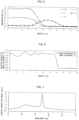
- Fig. 5 is a graph illustrating the concentration distribution of each element in the gain fiber 11 in accordance with the example shown in Table 8.
- Fig. 6 is a graph illustrating the distribution of refractive index of the gain fiber 11 in accordance with the Example shown in Table 8.
- the gain fiber 11 has a partiallydoped structure including an Yb, Al, P, and B-doped area at the center, and a Ge-doped area on the outside of the Yb, Al, P, and B-doped area. The concentrations of these elements are adjusted so that the core has a constant refractive index in their entireties, as illustrated in Fig. 5.
- Fig. 5 is a graph illustrating the concentration distribution of each element in the gain fiber 11 in accordance with the example shown in Table 8.
- Fig. 6 is a graph illustrating the distribution of refractive index of the gain fiber 11 in accordance with the Example shown in Table 8.
- the gain fiber 11 has a partiallydoped structure including an Yb, Al, P, and
- FIG. 7 is a graph illustrating the cladding absorption amount spectrum [dB/m] of the gain fiber 11 in accordance with the Example shown in Table 8.
- the shape of the cladding absorption amount spectrum is substantially identical to that of the standard absorption amount spectrum [dB/m] of Yb illustrated in Fig. 3 .
- a fiber laser in accordance with Aspect 1 of the present invention employs a configuration in which the fiber laser includes: a gain fiber having a core doped with Yb; and a forward pumping light source group capable of generating forward pumping light that is capable of being inputted into the gain fiber and that belongs to a 976-nm band, wherein an absorption amount of the forward pumping light in a section of the gain fiber, the section having a length of 1 m and including an end face on which the forward pumping light is incident, is not less than 253 W and not more than 1100 W as calculated according to ⁇ P( ⁇ )A( ⁇ )d ⁇ .
- P( ⁇ ) [W] is a power spectrum of the forward pumping light
- A( ⁇ ) [%/m] is an absorption rate spectrum of Yb with which the core of the gain fiber is doped.
- A1( ⁇ ) [%/m] is a standard absorption rate spectrum of Yb normalized at a wavelength of 978 nm
- A2 [%/m] is an absorption rate, at the wavelength of 978 nm, of Yb with which the core of the gain fiber is doped.
- a fiber laser in accordance with Aspect 3 of the present invention employs, in addition to the configuration of Aspect 1 or 2, a configuration in which the absorption amount of the forward pumping light in the section is not less than 634 W/m.
- a fiber laser in accordance with Aspect 4 of the present invention employs, in addition to the configuration of any one of Aspects 1 to 3, a configuration in which the forward pumping light has a total power of not less than 1509 W.
- a fiber laser in accordance with Aspect 5 of the present invention employs, in addition to the configuration of any one of Aspects 1 to 4, a configuration in which a value of an absorption amount of the forward pumping light emitted from the forward pumping light source group is not less than 206 W and not more than 358 W, when the value is a value obtained by calculating the absorption amount of the forward pumping light according to ⁇ P( ⁇ )A1( ⁇ )d ⁇ or a value obtained by dividing an actually measured value of the absorption amount of the forward pumping light by A2, wherein a pumping light absorption amount per unit length of the gain fiber at a wavelength of 978 nm is not less than 2.58 dB/m and not more than 3.07 dB/m.
- A1( ⁇ ) [%/m] is a standard absorption rate spectrum of Yb normalized at the wavelength of 978 nm
- A2 [%/m] is an absorption rate, at the wavelength of 978 nm, of Yb with which the core of the gain fiber is doped.
- a fiber laser in accordance with Aspect 6 of the present invention employs, in addition to the configuration of any one of Aspects 1 to 5, a configuration in which the gain fiber includes no fusion-spliced point, and has a constant refractive index distribution and a constant Yb concentration throughout its length.
- a fiber laser in accordance with Aspect 7 of the present invention employs a configuration in which the fiber laser including: a gain fiber having a core doped with Yb; and a forward pumping light source group capable of generating forward pumping light that is capable of being inputted into the gain fiber and that belongs to a 976-nm band, wherein an absorption amount of the forward pumping light in a section of the gain fiber, the section having a length of 1 m and including an end face on which the forward pumping light is incident, is not less than 253 W and not more than 1100 W, when the absorption amount of the forward pumping light in the section is an actually measured value of the absorption amount of the forward pumping light.
- a fiber laser in accordance with Aspect 8 of the present invention employs, in addition to the configuration of Aspect 7, a configuration in which the absorption amount of the forward pumping light in the section is not less than 634 W/m.
- a fiber laser in accordance with Aspect 9 of the present invention employs, in addition to the configuration of Aspect 7 or 8, a configuration in which the forward pumping light has a total power of not less than 1509 W.
- a fiber laser in accordance with Aspect 10 of the present invention employs, in addition to the configuration of any one of Aspects 7 to 9, a configuration in which a value of an absorption amount of the forward pumping light emitted from the forward pumping light source group is not less than 206 W and not more than 358 W, when the value is a value obtained by calculating the absorption amount of the forward pumping light according to ⁇ P( ⁇ )A1( ⁇ )d ⁇ or a value obtained by dividing an actually measured value of the absorption amount of the forward pumping light by A2, wherein a pumping light absorption amount per unit length of the gain fiber at a wavelength of 978 nm is not less than 2.58 dB/m and not more than 3.07 dB/m.
- A1( ⁇ ) [%/m] is a standard absorption rate spectrum of Yb normalized at the wavelength of 978 nm
- A2 [%/m] is an absorption rate, at the wavelength of 978 nm, of Yb with which the core of the gain fiber is doped.
- the present invention is not limited to the foregoing embodiments, but can be modified by a person skilled in the art within the scope of the claims.
- the present invention also encompasses, in its technical scope, any embodiment derived by combining technical means disclosed in the foregoing embodiments.
Landscapes
- Physics & Mathematics (AREA)
- Electromagnetism (AREA)
- Engineering & Computer Science (AREA)
- Plasma & Fusion (AREA)
- Optics & Photonics (AREA)
- Lasers (AREA)
Abstract
Description
- The present invention relates to a fiber laser including a gain fiber having a core doped with Yb.
- Fiber lasers each including, as a gain fiber, a double cladding fiber having a core doped with ytterbium (Yb) are widely used. Primary absorption bands of Yb in glass are a 915-nm band and a 976-nm band. Thus, such fiber lasers each has a configuration in which pumping light belonging to the 915-nm band or 976-nm band is supplied to the cladding of the gain fiber, to excite Yb with which the core is doped (to cause transition to the population inversion state). To increase the output power of such a fiber laser, the power of pumping light may be increased and the concentration of Yb may be increased, so as to achieve sufficient amplification in the gain fiber.
- [Non-patent Literature 1]
C. Jauregui et al., "Physical origin of mode instabilities in high-power fiber laser systems", Opt. Express 20(12) 12912-12925 (2012) - In such a fiber laser, there may be problems in that the increase in power of pumping light and the increase in the concentration of Yb may lead transverse mode instability (TMI) to occur, which increases the rate of light in higher order mode included in laser light outputted from the fiber laser, that is, which decreases beam output power of the laser light outputted from the fiber laser (Non-Patent Literature 1). In addition, there may be problems in that, if a mode filter for removing higher order mode light is used to prevent a decrease in beam output power, the power of laser light outputted from the fiber laser decreases.
- For example, a mechanism by which beam output power decreases when the TMI occurs can be explained as follows. That is, inter-mode interference between the fundamental mode and the higher order mode guided through the core occurs; this causes the signal light amount to spatially vary along the longitudinal direction of the gain fiber. This makes the induced emitted amount spatially vary along the longitudinal direction of the gain fiber, so that the amount of heat generation due to quantum defect spatially varies along the longitudinal direction of the gain fiber. As a result, the temperature spatially varies along the longitudinal direction of the gain fiber, so that the refractive index spatially varies along the longitudinal direction of the gain fiber. This variation in refractive index facilitates the transition from the fundamental mode to the higher order mode, so that the abovementioned decrease in beam output power occurs.
- To prevent a decrease in beam output power caused by the TMI without changing the total amount of Yb, one option is to increase the length of the gain fiber. However, the increase in the length of the gain fiber may give rise to another problem that stimulated Raman scattering, which causes a failure of the pumping light source, may be likely to occur.
- An aspect of the present invention has been made in view of such circumstances, and an object of the aspect is to realize a fiber laser which reduces the probability of a decrease in beam output power due to the TMI and also reduces the probability of occurrence of stimulated Raman scattering.
- A fiber laser in accordance with an aspect of the present invention employs a configuration in which the fiber laser including: a gain fiber having a core doped with Yb; and a forward pumping light source group capable of generating forward pumping light that is capable of being inputted into the gain fiber and that belongs to a 976-nm band, wherein an absorption amount of the forward pumping light in a section of the gain fiber, the section having a length of 1 m and including an end face on which the forward pumping light is incident, is not less than 253 W and not more than 1100 W as calculated according to ∫P(λ)A(λ)dλ.
- Herein, P(λ) [W] is a power spectrum of the forward pumping light, and A(λ) [%/m] is an absorption rate spectrum of Yb with which the core of the gain fiber is doped.
- A fiber laser in accordance with another aspect of the present invention employs a configuration in which the fiber laser including: a gain fiber having a core doped with Yb; and a forward pumping light source group capable of generating forward pumping light that is capable of being inputted into the gain fiber and that belongs to a 976-nm band, wherein an absorption amount of the forward pumping light in a section of the gain fiber, the section having a length of 1 m and including an end face on which the forward pumping light is incident, is not less than 253 W and not more than 1100 W, when the absorption amount of the forward pumping light in the section is an actually measured value of the absorption amount of the forward pumping light.
- According to an aspect of the present invention, it is possible to realize a fiber laser which reduces the probability of a decrease in beam output power due to the TMI and also reduces the probability of occurrence of stimulated Raman scattering.
-
-
Fig. 1 is a block diagram illustrating a configuration of a fiber laser in accordance with an embodiment of the present invention. -
Fig. 2 is a graph illustrating, regarding multiple fiber lasers prepared as samples, the relationship between the pumping light absorption amount in section I1 and the rejection rate. -
Fig. 3 is a graph illustrating a standard absorption amount spectrum [dB/m] of Yb. -
Fig. 4 is a graph illustrating, regarding multiple fiber lasers prepared as samples, the distribution of accepted products and rejected products, in which the horizontal axis represents the pumping light absorption amount [dB/m] per unit length of a gain fiber at a wavelength of 978 nm, and the vertical axis represents the absorption amount of forward pumping light emitted from a forward pumping light source (LDM forward pumping light absorption amount). -
Fig. 5 is a graph illustrating the concentration distribution of each element in the gain fiber in accordance with an Example shown in Table 8. -
Fig. 6 is a graph illustrating the distribution of relative refractive index of the gain fiber in accordance with the Example shown in Table 8. -
Fig. 7 is a graph illustrating the cladding absorption amount spectrum in accordance with the Example shown in Table 8. - A configuration of a
fiber laser 1 in accordance with an embodiment of the present invention will be described with reference toFig. 1. Fig. 1 is a block diagram illustrating the configuration of thefiber laser 1. - As illustrated in
Fig. 1 , thefiber laser 1 includes again fiber 11, a high-reflective mirror 12, a low-reflective mirror 13, aforward pumping combiner 14a, abackward pumping combiner 14b, a forward pumpinglight source group 15a, a backward pumpinglight source group 15b, aninput fiber 16a, and anoutput fiber 16b. - The
gain fiber 11 is an optical fiber that has a function of amplifying laser light with use of energy of pumping light. According to the present embodiment, as thegain fiber 11, used is an Yb-doped double cladding fiber, which is an optical fiber that has a columnar core doped with ytterbium (Yb), a tubular inner cladding surrounding the core, and a tubular outer cladding surrounding the inner cladding. The cross-sectional shape of the inner cladding may be polygonal, or may be D-shaped. This enables efficient absorption of pumping light without decreasing the absorption rate of the pumping light, even in a case in which thegain fiber 11 is long. The distribution of refractive index of thegain fiber 11 is set so that thegain fiber 11 propagates one fundamental mode and at least one higher order mode. In addition, thegain fiber 11 includes no fusion-spliced point, and has a constant refractive index distribution and a constant Yb concentration throughout its length. This configuration enables elimination of connection loss, so that it is possible to reduce the total loss occurring in thegain fiber 11. - To one end of the
gain fiber 11, the high-reflective mirror 12 is connected (by fusion splicing, in the present embodiment). To the other end of thegain fiber 11, the low-reflective mirror 13 is connected (by fusion splicing, in the present embodiment). According to the present embodiment, fiber Bragg gratings (FBGs) are used as the high-reflective mirror 12 and the low-reflective mirror 13. - In the
fiber laser 1, at least a part of the reflection wavelength band of the high-reflective mirror 12 and at least a part of the reflection wavelength band of the low-reflective mirror 13 overlap. With this, thegain fiber 11, the high-reflective mirror 12, and the low-reflective mirror 13 constitute a resonator O that recursively amplifies laser light with wavelength λ that belongs to the overlap between the two reflection wavelength bands. At wavelength λ, the reflectance of the low-reflective mirror 13 (e.g., not more than 15%) is lower than that of the high-reflective mirror 12 (e.g., not less than 95%). Thus, laser light with wavelength λ that has been recursively amplified by the resonator O is outputted externally from the resonator O, mainly passing through the low-reflective mirror 13. - The forward pumping
light source group 15a includes ma pumping light source or sources (ma is any natural number). Each pumping light source included in the forward pumpinglight source group 15a is configured to generate pumping light that belongs to the 976-nm band. As used herein, the 976-nm band refers to a wavelength band of not less than 967.9 nm and not more than 983.0 nm, in which the absorption band of Yb is included. Theforward pumping combiner 14a is configured to input, into thegain fiber 11, pumping light generated by the respective pumping light sources included in the forward pumpinglight source group 15a. Theforward pumping combiner 14a includes at least ma pumping light input port or ports 14a1, at least one visible light input port 14a2, and at least one resonator-side port 14a3. Every pumping light input port 14a1 is connected to the corresponding pumping light source constituting the forward pumpinglight source group 15a. The visible light input port 14a2 is connected to theinput fiber 16a (by fusion splicing, in the present embodiment), and is for use in visual observation of the irradiation positions of laser light. It should be noted that the input of visible light into the visible light input port 14a2 is not essential, and the visible light input port 14a2 may be used as a port for inputting pumping light, or alternatively, may be used as a port for monitoring the amount of light reflected in a workpiece. The resonator-side port 14a3 is connected (by fusion splicing, in the present embodiment) to an end of the high-reflective mirror 12 on a side opposite to thegain fiber 11 side. - Forward pumping light generated in each pumping light source of the forward pumping
light source group 15a is guided through the forward pumping combiner 14a and the high-reflective mirror 12 to the cladding of thegain fiber 11, in which the forward pumping light is used to cause transition of the state of Yb, with which the core of thegain fiber 11 is doped, to the population inversion state. Among spontaneous emission light waves generated in thegain fiber 11, a light wave with wavelength λ that matches the reflection wavelengths of the high-reflective mirror 12 and the low-reflective mirror 13 is amplified by the resonator O in the core of thegain fiber 11. According to the present embodiment, as the forward pumpinglight source group 15a, a pumping light source group obtained by connecting six LD modules each including 13 laser diode (LD) chips is used (ma=78). Each LD chip is designed to have the oscillation wavelength band with a central wavelength of about 975 nm (absorption wavelength of Yb) and with a wavelength width of not less than 7 nm and not more than 12 nm.Fig. 1 depicts six LD modules constituting the forward pumpinglight source group 15a. Pumping light waves emitted from 13 LD chips, not illustrated, per LD module are coupled to a single optical fiber. That is, pumping light waves emitted from the 78 LD chips in total are combined in theforward pumping combiner 14a, and the combined light is coupled to the resonator-side port 14a3, which is a single optical fiber. - The backward pumping
light source group 15b includes mb pumping light source or sources (mb is any natural number). Each pumping light source included in the backward pumpinglight source group 15b is configured to generate pumping light that belongs to the 976-nm band. Thebackward pumping combiner 14b is configured to input, into thegain fiber 11, pumping light generated by the respective pumping light sources included in the backward pumpinglight source group 15b. Thebackward pumping combiner 14b includes at least mb pumping light input port or ports 14b1, at least one signal light output port 14b2, and at least one resonator-side port 14b3. Every pumping light input port 14b1 is connected to the corresponding pumping light source constituting the backward pumpinglight source group 15b. The signal light output port 14b2 is connected to theoutput fiber 16b (by fusion splicing, in the present embodiment). The resonator-side port 14b3 is connected (by fusion splicing, in the present embodiment) to an end of the low-reflective mirror 13 on a side opposite to thegain fiber 11 side. - Backward pumping light generated in each pumping light source of the backward pumping
light source group 15b is guided through thebackward pumping combiner 14b and the low-reflective mirror 13 to the cladding of thegain fiber 11, in which the backward pumping light is used to cause transition of the state of Yb, with which the core of thegain fiber 11 is doped, to the population inversion state. Signal light (laser light) amplified by the core of thegain fiber 11 is guided through the low-reflective mirror 13 and thebackward pumping combiner 14b to theoutput fiber 16b, and then output externally through theoutput fiber 16b. According to the present embodiment, as the backward pumpinglight source group 15b, a pumping light source group obtained by connecting six LD modules each including 13 laser diode (LD) chips is used (mb=78). Each LD chip is designed to have the oscillation wavelength band with a central wavelength of about 975 nm (absorption wavelength of Yb) and with a wavelength width of not less than 7 nm and not more than 12 nm.Fig. 1 depicts six LD modules constituting the backward pumpinglight source group 15b. Pumping light waves emitted from 13 LD chips, not illustrated, per LD module are coupled to a single optical fiber. That is, pumping light waves emitted from the 78 LD chips in total are combined in thebackward pumping combiner 14b, and the combined light is coupled to the resonator-side port 14b3, which is a single optical fiber. - It should be noted that, in the present embodiment, the
fiber laser 1 is realized as a fiber laser of a bidirectional pumping type which includes the forward pumpinglight source group 15a and the backward pumpinglight source group 15b; however, the present invention is not limited thereto. That is, thefiber laser 1 may be alternatively realized as a fiber laser of a unidirectional pumping type which includes only the forward pumpinglight source group 15a. - Transverse mode instability (TMI) mainly occurs in section I1 of the
gain fiber 11, the section I1 having a length of 1 m and including the end face on which forward pumping light is incident. This is because the absorption amount of forward pumping light in the section I1 is greater than that in an area other than the section I1, and thus, an amount of heat generated in this section I1 is greater than that in the area other that the section I1. Therefore, to prevent a decrease in beam output power caused by the TMI, it is necessary to reduce the absorption amount of forward pumping light in this section I1. - Thus, the inventors of the present invention prepared 436
fiber lasers 1 as samples, and carried out an acceptance test in which the following acceptance criteria is employed: whether or not the maximum output power of the laser output power, obtained as the total output power of the forward pumpinglight source group 15a and the backward pumpinglight source group 15b, is not less than 2070 W.Fig. 2 is a graph illustrating the relationship between the pumping light absorption amount in the section I1 and the rejection rate. The graph ofFig. 2 reveals that the rejection rate can be reduced to about half or less by reducing the absorption amount of forward pumping light in the section I1 to not more than 1100 W. The graph ofFig. 2 also reveals that the rejection rate can be reduced to about four-tenths or less by reducing the absorption amount of forward pumping light in the section I1 to not more than 1050 W. Further, the graph ofFig. 2 also reveals that the rejection rate can be reduced to about three-tenths or less by reducing the absorption amount of forward pumping light in the section I1 to not more than 1000 W. - It is preferable that the
gain fiber 11 have a shorter length, in order to reduce stimulated Raman scattering. For example, when the effective cross-sectional area of thegain fiber 11 is 400 µm2, it is preferable that thegain fiber 11 have a length of not more than 27 m. Here, when the effective cross-sectional area is 400 µm2, the following (1) to (3) may tend to be appropriately achieved at the same time. - (1) The number of waveguide modes of light can be two, that is, light in LP01 mode and light in LP11 mode. Therefore, a decrease in beam quality due to the number of waveguide modes of light can be minimized.
- (2) Bending loss in both the LP01 mode and the LP11 mode can be reduced.
- (3) Because the effective cross-sectional area relatively increases, nonlinear optical effect can be effectively reduced.
- Here, the effective cross-sectional area of the
gain fiber 11 can be increased by increasing the core diameter of thegain fiber 11; however, the greater the core diameter is, the greater the V value is, so that even if thegain fiber 11 is bent, light in LP02 mode propagates. When light in the LP02 mode propagates through thegain fiber 11 in this way, this may cause the TMI. Further, although it is possible to increase the effective cross-sectional area by decreasing the relative refractive index difference of the core of thegain fiber 11, such a decrease in the relative refractive index difference of the core may increase the bending loss of thegain fiber 11, so that light in the LP01 mode and light in the LP11 mode, which are to be outputted as laser output light, may be susceptible to effects of the bending loss, resulting in increase in propagation losses of light in the LP01 mode and light in the LP11 mode. - Therefore, the value of the effective cross-sectional area that can appropriately achieve the abovementioned (1) to (3) at the same time can be 400 µm2. In addition, when it is herein assumed that the length of the
gain fiber 11 is L and the effective cross-sectional area is Aeff, and when the laser output power of thefiber laser 1 is targeted at 2 kW in a case in which the effective cross-sectional area of thegain fiber 11 is 400 µm2, it is necessary to set L/Aeff, which is proportional to the nonlinear optical effect, to not more than 27 m/400 µm2, in order to reduce the nonlinear optical effect. Thus, it is necessary to set the length of thegain fiber 11 to not more than 27 m from the viewpoint of reduction in the nonlinear optical effect. - Further, in order to reduce the overheating of each component, it is preferable to reduce residual pumping light, that is, it is preferable to increase the absorption amount of pumping light in the
gain fiber 11. For example, as an example of thefiber laser 1, which is described later, when the total output power of the forward pumpinglight source group 15a is 1611 W, it is preferable to set the power of residual pumping light to not more than 16 W, that is, it is preferable to set the pumping light absorption amount in thegain fiber 11 to not less than 20 dB, from the viewpoint of ensuring the long-term reliable reduction in heat generated due to the residual pumping light. This value is obtained from anexpression 10×log(Pout/Pin), using output power Pout of the residual pumping light and total output power Pin of the forward pumpinglight source group 15a, thereby calculating 10×log(16/1611)≈20dB. Here, in order to set, to not less than 20 dB, the pumping light absorption amount in thegain fiber 11 having a length of not more than 27 m to provide an effective cross-sectional area of 400 µm2 as discussed above, it is necessary to set the absorption amount of pumping light per unit length to not less than 0.74 dB/m, so that it is necessary to set the absorption rate of pumping light per unit length to not less than 15.68%. This value is obtained from an expression of (1-10^(0.74/10))×100, using absorption amount AA (dB/m) of pumping light per unit length, thereby calculating (1-10^(0.74/10))×100≈15.68%. At this time, the absorption amount of forward pumping light in the abovementioned section I1 is not less than 253 W on the basis of the foregoing results. This value is obtained from an expression of W×AB/100, using total output power W of the forward pumpinglight source group 15a and absorption amount AB (%) of pumping light per unit length, thereby calculating 1611×15.68/100≈253W. - Taking into account the foregoing, the
fiber laser 1 in accordance with the present embodiment employs a configuration in which the absorption amount of forward pumping light in the section I1 is not less than 253 W and not more than 1100 W. This allows thefiber laser 1 in accordance with the present embodiment to achieve advantageous effects that the probability of decrease in beam output power due to the TMI is reduced, and that the probability of occurrence of stimulated Raman scattering is reduced without overheating of each component. - It should be noted that, in the
fiber laser 1, (1) as the absorption amount of forward pumping light in the section I1, a calculated absorption amount of not less than 253 W and not more than 1100 W may be used, or alternatively, (2) as the absorption amount of forward pumping light in the section I1, an actually measured value of the actually measured absorption amount of not less than 253 W and not more than 1100 W may be used. In both cases, the abovementioned effects are achieved. - Absorption amount X [W] of forward pumping light in the section I1 may be calculated according to X=∫P(λ)A(λ)dλ, using, for example, power spectrum P(λ) [W] of forward pumping light outputted from the forward pumping
light source group 15a and absorption rate spectrum A(λ) [%/m] of Yb with which the core of thegain fiber 11 is doped. - This absorption rate spectrum A(λ) of Yb may be obtained by calculation, or alternatively, by actual measurement. When being obtained by calculation, the absorption rate spectrum A(λ) of Yb can be calculated according to A(λ)=A1(λ)×A2, using, for example, standard absorption rate spectrum A1(λ)[%/m] (theoretical value) of Yb normalized at the wavelength of 978 nm and absorption rate A2 [%/m] (actually measured value), at the wavelength of 978 nm, of Yb with which the core of the
gain fiber 11 is doped. In this case, the absorption amount X [W] of forward pumping light in the section I1 is calculated according to X=∫P(λ)A1(λ)A2dλ. A standard absorption amount spectrum [dB/m] of Yb is illustrated inFig. 3 . The abovementioned standard absorption rate spectrum A(λ) can be obtained by converting the absorption amount spectrum [dB/m] illustrated inFig. 3 into the absorption rate spectrum [%/m] and by normalizing the obtained absorption rate spectrum [%/m] so that a value at the wavelength of 978 nm becomes 100%. - Instead of the configuration in which the absorption spectrum A(λ) of Yb is calculated by using the absorption rate of Yb at the wavelength of 978 nm, a configuration in which the absorption spectrum A(λ) of Yb is calculated by using an absorption rate of Yb at another wavelength (966 nm, 915 nm, etc.) may be employed. The reason why the absorption rate of Yb at the wavelength of 978 nm is used is that the difference between the wavelength of 978 nm and the wavelength of forward pumping light to be actually used is small, and thus, it is possible to more accurately calculate the absorption amount of forward pumping light in the section I1, compared to another wavelength. Actually, in a case in which the absorption rate of Yb at another absorption wavelength is used, the absorption rate can be measured with higher accuracy compared to a case in which the absorption rate at the wavelength of 978 nm is used, but an inaccurate absorption amount of forward pumping light in the section I1 is calculated due to a great difference between said another absorption wavelength and the wavelength of the forward pumping light to be actually used. It should be noted that the reason why the absorption rate of Yb at another absorption wavelength can be measured with higher accuracy is that the absorption amount is less than that at the wavelength of 978 nm; this enables a measurement using a long gain fiber, so that it is possible to reduce the effects of errors occurring when the cutback measurement is performed.
- Further, the power spectrum P(λ) of forward pumping light may be obtained by calculation, or alternatively, by actual measurement. When being obtained by calculation, the power spectrum P(λ) of forward pumping light can be calculated according to P(λ)=∑i=1,2,...,maPi(λ), using, for example, output power spectrum Pi(λ) of each forward pumping light source included in the forward pumping
light source group 15a. As the output power spectrum Pi(λ) of each forward pumping light source, an actually measured distribution may be used, or alternatively, an approximate distribution (Gaussian distribution reproducing the central wavelength and the wavelength width of the actual power spectrum) may be used. In addition, when an LD module including multiple LD chips is used as the forward pumping light source as in the present embodiment, the output power spectrum Pi(λ) of the LD module may be obtained as follows: that is, the representative value (an average value, a median value, etc.) of the central wavelengths of the respective LD chips is deemed as the central wavelength of the LD module, and the representative value of the wavelength widths of the respective LD chips is deemed as the wavelength width of the LD module, and then, the Gaussian distribution reproducing the central wavelength and the wavelength width is used as the output power spectrum Pi(λ) of the LD module. -
Fig. 4 is a graph illustrating, regardingfiber lasers 1 prepared as samples, the distribution of accepted products and rejected products, in which the horizontal axis represents the pumping light absorption amount [dB/m] per unit length of thegain fiber 11 at the wavelength of 978 nm (indicated inFig. 4 by "Yb ABSORPTION AMOUNT AT WAVELENGTH OF 978 nm" [dB/m]), and the vertical axis represents the absorption amount of forward pumping light emitted from the forward pumping light source (LDM forward pumping light absorption amount) (indicated inFig. 4 by "FORWARD ABSORPTION" [W]). -
Fig. 4 reveals that thegain fiber 11 satisfying the following conditions has a rejection rate reduced to about half. That is, the conditions are that the absorption amount of forward pumping light emitted from the forward pumping light source (corresponding to "forward pumping light absorption amount (in other words, the LDM forward pumping light absorption amount)" inFig. 4 ) is not less than 206 W and not more than 358 W, and the pumping light absorption amount per unit length of thegain fiber 11 at the wavelength of 978 nm (corresponding to the "pumping light absorption amount (in other words, the Yb absorption amount at 978 nm)" inFig. 4 ) is not less than 2.58 dB/m and not more than 3.07 dB/m. Further, as to thegain fibers 11 satisfying the conditions, when an average output power of the laser output powers of thefiber lasers 1 each obtained by a total output power of both the forward pumpinglight source group 15a and the backward pumpinglight source group 15b is calculated by averaging values of output powers of the accepted products illustrated inFig. 4 , the average output power is 2110 W. In contrast, as to thegain fibers 11 failing to satisfy the conditions, when an average output power of the laser output power of thefiber laser 1 obtained by the total output power is calculated by averaging values of output power of the rejected products illustrated inFig. 4 , the average output power is 2068 W. Therefore, thegain fibers 11 satisfying the conditions have advantages in that they have greater average output power than that of thegain fibers 11 failing to satisfy the conditions (i.e., power consumption decreases in rated power operation). InFig. 4 , the solid line indicates a curve that represents data points where the absorption amount of forward pumping light (forward pumping light absorption amount) calculated by using ∫P(λ)A1(λ)A2d2λ is 253 W (i.e., a curve denoted inFig. 4 as "PUMPING LIGHT ABSORPTION AMOUNT 253 W"), and the dotted line indicates a curve that represents data points where the absorption amount of forward pumping light (forward pumping light absorption amount) calculated by using ∫P(λ)A1(λ)A2dλ is 1100 W (i.e., a curve denoted inFig. 4 as "PUMPING LIGHT ABSORPTION AMOUNT 1100 W").Fig. 4 reveals that an area in which the abovementioned conditions are satisfied are located between these two curves. It is therefore understood that the condition "the absorption amount of forward pumping light calculated by using ∫P(λ)A1(λ)A2dλ is not less than 253 W and not more than 1100 W" is essentially satisfied when the abovementioned conditions are satisfied. Furthermore, as a value of the abovementioned absorption amount of forward pumping light emitted from the forward pumping light source (LDM forward pumping light absorption amount), a calculated value of the absorption amount of the forward pumping light calculated according to ∫P(λ)A1(λ)dλ may be used, or alternatively, a value obtained by dividing an actually measured value of the absorption amount of the forward pumping light by A2 may be used. Herein, A1(λ) [%/m] (theoretical value) is a standard absorption rate spectrum of Yb normalized at the wavelength of 978 nm. A2 [%/m] (actually measured value) is an absorption rate, at the wavelength of 978 nm, of Yb with which the core of the gain fiber is doped. - As Examples and Comparative Examples of the
fiber laser 1, elevenfiber lasers 1 were selected from the 436fiber lasers 1 prepared as samples, and each of the selectedfiber lasers 1 was evaluated for the following parameters, results of which are shown in Tables 1 to 11. - (1) Central wavelength [nm] of each LD module of the forward pumping
light source group 15a ("LD central wavelength [nm]" of Tables 1 to 11) - (2) Wavelength width [nm] of each LD module of the forward pumping
light source group 15a ("LD wavelength width [nm]" of Tables 1 to 11) - (3) Pumping light absorption amount [dB/m] per unit length of the
gain fiber 11 at the wavelength of 978 nm (Yb "Yb 978-nm absorption amount [dB/m]" of Tables 1 to 11) - (4) Absorption amount [W], in the section I1, of forward pumping light outputted from each LD module of the forward pumping
light source group 15a ("Forward absorption × 978 absorption amount [W]" of Tables 1 to 11) - (5) Absorption amount [W], in the section I1, of forward pumping light outputted from the forward pumping
light source group 15a (calculated according to ∫P(λ)A1(λ)A2dλ) ("Total absorption amount [W]" of Tables 1 to 11) - (6) Output power [W] of the forward pumping
light source group 15a ("Pumping light output power [W]" of Tables 1 to 11) - (7) Output power [W] of the fiber laser 1 ("Output power [W]" of Tables 1 to 11)
- (8) Results of the acceptance test ("Accepted/rejected" of Tables 1 to 11)
- Regarding Items (4) and (5), it should be noted that, in some of Tables 1 to 11 below, the sum of the absorption amounts, in the section I1, of forward pumping light outputted from the respective LD modules of the forward pumping
light source group 15a is not equal to the value of the absorption amount, in the section I1, of forward pumping light outputted from the forward pumpinglight source group 15a. This is because the absorption amounts, in the section I1, of forward pumping light outputted from the respective LD modules were obtained in a manner such that values are rounded up or down to the nearest whole numbers. Thus, in reviewing each of the Examples and the Comparative Examples, the sum of the absorption amounts, in the section I1, of forward pumping light outputted from the respective LD modules of the forward pumpinglight source group 15a and the value of the absorption amount, in the section I1, of forward pumping light outputted from the forward pumpinglight source group 15a may be deemed to be the same.[Table 1] LDM Nos. LD central wavelength [nm] LD wavelength width [nm] Yb 978-nm absorption amount [dB/m] Forward absorption × 978 absorption amount [W] Total absorption amount [W] Pumping light output power [W] Output power [W] Accepted /rejected 2.62 707 1548 2088 Accepted 1 973.6 7.7 114 2 973.9 7.6 120 3 973.9 8.0 120 4 974.1 8.0 124 5 974.1 8.3 124 6 973.1 7.3 104 [Table 2] LDM Nos. LD central wavelength [nm] LD wavelength width [nm] Yb 978-nm absorption amount [dB/m] Forward absorption × 978 absorption amount [W] Total absorption amount [W] Pumping light output power [W] Output power [W] Accepted /rejected 2.62 815 1611 2161 Accepted 1 974.0 8.2 122 2 974.2 7.9 126 3 974.6 7.8 134 4 974.4 7.7 131 5 975.6 8.0 149 6 975.9 7.5 152 [Table 3] LDM Nos. LD central wavelength [nm] LD wavelength width [nm] Yb 978-nm absorption amount [dB/m] Forward absorption × 978 absorption amount W Total absorption amount [W] Pumping light output power [W] Output power [W] Accepted /rejected 2.80 910 1568 2200 Accepted 1 975.5 7.9 159 2 975.9 8.8 159 3 974.3 8.4 137 4 974.6 8.8 142 5 975. 8 9.1 162 6 975.8 7.7 152 [Table 4] LDM Nos. LD central wavelength [nm] LD wavelength width [nm] Yb 978-nm absorption amount [dB/m] Forward absorption × 978 absorption amount [W] Total absorption amount [W] Pumping light output power [W] Output power [W] Accepted /rejected 3.27 1095 1544 2119 Accepted 1 976.3 10.9 180 2 978.2 7.5 178 3 978.0 9.0 177 4 976.1 8.6 188 5 977.4 9.1 184 6 977.1 8.6 188 [Table 5] LDM Nos. LD central wavelength [nm] LD wavelength width [nm] Yb 978-nm absorption amount [dB/m] Forward absorption × 978 absorption amount [W] Total absorption amount [W] Pumping light output power [W] Output power [W] Accepted /rejected 2.95 1003 1596 2145 Accepted 1 977.0 8.2 171 2 977.4 8.5 168 3 977.6 7.5 170 4 978.0 8.4 161 5 978.0 8.0 162 6 976.0 7.7 172 [Table 6] LDM Nos. LD central wavelength [nm] LD wavelength width [nm] Yb 978-run absorption amount [dB/m] Forward absorption × 978 absorption amount [W] Total absorption amount [W] Pumping light output power [W] Output power [W] Accepted /rejected 2.95 634 1595 2188 Accepted 1 971.9 7.9 94 2 972.2 7.6 99 3 972.8 7.5 110 4 972.9 7.7 113 5 972.7 7.4 108 6 972.8 7.6 110 [Table 7] LDM Nos. LD central wavelength [nm] LD wavelength width [nm] Yb 978-run absorption amount [dB/m] Forward absorption × 978 absorption amount [W] Total absorption amount [W] Pumping light output power [W] Output power [W] Accepted I rejected 2.80 897 1579 2161 Accepted 1 974.8 7.2 148 2 975.0 8.4 149 3 974.6 8.0 143 4 976.3 10.4 155 5 975.9 8.2 161 6 975.0 12.0 141 [Table 8] LDM Nos. LD central wavelength [run] LD wavelength width [nm] Yb 978-nm absorption amount [dB/m] Forward absorption × 978 absorption amount [W] Total absorption amount [W] Pumping light output power [W] Output power [W] Accepted /rejected 2.77 931 1517 2106 Accepted 1 975.9 9.9 153 2 975.1 7.8 150 3 976.7 10.4 154 4 975.6 8.1 157 5 975.7 8.2 158 6 975.6 7.6 159 [Table 9] LDM Nos. LD central wavelength [run] LD wavelength width [nm] Yb 978-nm absorption amount [dB/m] Forward absorption × 978 absorption amount [W] Total absorption amount [W] Pumping light output power [W] Output power [W] Accepted /rejected 2.95 859 1509 2150 Accepted 1 973.6 13.8 127 2 974.2 8.3 142 3 977.7 9.8 161 4 973.8 8.3 133 5 974.1 7.6 140 6 975.1 9.9 155 [Table 10] LDM Nos. LD central wavelength [mn] LD wavelength width [nm] Yb 978-run absorption amount [dB/m] Forward absorption × 978 absorption amount [W] Total absorption amount [W] Pumping light output power [W] Output power [W] Accepted /rejected 3.97 1323 1573 1942 Rejected 1 979.1 8.0 191 2 977.7 9.9 216 3 976.1 8.7 228 4 977.4 8.0 229 5 976.9 8.4 230 6 976.7 8.8 229 [Table 11] LDM Nos. LD central wavelength [nm] LD wavelength width [run] Yb 978-run absorption amount [dB/m] Forward absorption × 978 absorption amount [W] Total absorption amount [W] Pumping light output power [W] Output power [W] Accepted /rejected 3.59 1203 1565 2010 Rejected 1 977.4 8.6 204 2 977.6 7.8 205 3 977.9 7.5 201 4 978.0 8.1 197 5 978.7 7.7 184 6 977.0 7.5 212 - Since each of the
fiber lasers 1 shown in Tables 1 to 9 satisfies the condition that the absorption amount of forward pumping light in the section I1 is not less than 253 W and not more than 1100 W, thesefiber lasers 1 are Examples. Since each of thefiber lasers 1 shown in Tables 10 and 11 fails to satisfy the condition that the absorption amount of forward pumping light in the section I1 is not less than 253 W and not more than 1100 W, thesefiber lasers 1 are Comparative Examples. It can be seen from the Tables that thefiber lasers 1 of the Examples were determined to be accepted products, whereas thefiber lasers 1 of the Comparative Examples were determined to be rejected products. - Further, each of the
fiber lasers 1 which were determined to be accepted products has an absorption amount, in the section I, of forward pumping light outputted from the forward pumpinglight source group 15a of not less than 634 W/m. Thus, the Examples suggest that the absorption amount of forward pumping light in the section I may be preferably not less than 634 W/m, in order to reduce the rejection rate (i.e., in order to reduce the probability of a decrease in beam output power caused by the TMI). - Furthermore, regarding the
fiber lasers 1 which were determined to be accepted products, the total power of forward pumping light, that is, the output power of the forward pumpinglight source group 15a is not less than 1509 W. Thus, the Examples suggest that the total power of forward pumping light may be preferably not less than 1509 W, in order to reduce the rejection rate (i.e., in order to reduce the probability of a decrease in beam output power caused by the TMI). -
Fig. 5 is a graph illustrating the concentration distribution of each element in thegain fiber 11 in accordance with the example shown in Table 8.Fig. 6 is a graph illustrating the distribution of refractive index of thegain fiber 11 in accordance with the Example shown in Table 8. As illustrated inFig. 5 , thegain fiber 11 has a partiallydoped structure including an Yb, Al, P, and B-doped area at the center, and a Ge-doped area on the outside of the Yb, Al, P, and B-doped area. The concentrations of these elements are adjusted so that the core has a constant refractive index in their entireties, as illustrated inFig. 5. Fig. 7 is a graph illustrating the cladding absorption amount spectrum [dB/m] of thegain fiber 11 in accordance with the Example shown in Table 8. The shape of the cladding absorption amount spectrum is substantially identical to that of the standard absorption amount spectrum [dB/m] of Yb illustrated inFig. 3 . - A fiber laser in accordance with
Aspect 1 of the present invention employs a configuration in which the fiber laser includes: a gain fiber having a core doped with Yb; and a forward pumping light source group capable of generating forward pumping light that is capable of being inputted into the gain fiber and that belongs to a 976-nm band, wherein an absorption amount of the forward pumping light in a section of the gain fiber, the section having a length of 1 m and including an end face on which the forward pumping light is incident, is not less than 253 W and not more than 1100 W as calculated according to ∫P(λ)A(λ)dλ. - Herein, P(λ) [W] is a power spectrum of the forward pumping light, and A(λ) [%/m] is an absorption rate spectrum of Yb with which the core of the gain fiber is doped.
- A fiber laser in accordance with
Aspect 2 of the present invention employs, in addition to the configuration ofAspect 1, a configuration in which the absorption rate spectrum A(λ) is calculated according to A(λ)=A1(λ)×A2. - Herein, A1(λ) [%/m] is a standard absorption rate spectrum of Yb normalized at a wavelength of 978 nm, and A2 [%/m] is an absorption rate, at the wavelength of 978 nm, of Yb with which the core of the gain fiber is doped.
- A fiber laser in accordance with
Aspect 3 of the present invention employs, in addition to the configuration ofAspect - A fiber laser in accordance with
Aspect 4 of the present invention employs, in addition to the configuration of any one ofAspects 1 to 3, a configuration in which the forward pumping light has a total power of not less than 1509 W. - A fiber laser in accordance with Aspect 5 of the present invention employs, in addition to the configuration of any one of
Aspects 1 to 4, a configuration in which a value of an absorption amount of the forward pumping light emitted from the forward pumping light source group is not less than 206 W and not more than 358 W, when the value is a value obtained by calculating the absorption amount of the forward pumping light according to ∫P(λ)A1(λ)dλ or a value obtained by dividing an actually measured value of the absorption amount of the forward pumping light by A2, wherein a pumping light absorption amount per unit length of the gain fiber at a wavelength of 978 nm is not less than 2.58 dB/m and not more than 3.07 dB/m. - Herein, A1(λ) [%/m] is a standard absorption rate spectrum of Yb normalized at the wavelength of 978 nm, and A2 [%/m] is an absorption rate, at the wavelength of 978 nm, of Yb with which the core of the gain fiber is doped.
- A fiber laser in accordance with
Aspect 6 of the present invention employs, in addition to the configuration of any one ofAspects 1 to 5, a configuration in which the gain fiber includes no fusion-spliced point, and has a constant refractive index distribution and a constant Yb concentration throughout its length. - A fiber laser in accordance with Aspect 7 of the present invention employs a configuration in which the fiber laser including: a gain fiber having a core doped with Yb; and a forward pumping light source group capable of generating forward pumping light that is capable of being inputted into the gain fiber and that belongs to a 976-nm band, wherein an absorption amount of the forward pumping light in a section of the gain fiber, the section having a length of 1 m and including an end face on which the forward pumping light is incident, is not less than 253 W and not more than 1100 W, when the absorption amount of the forward pumping light in the section is an actually measured value of the absorption amount of the forward pumping light.
- A fiber laser in accordance with
Aspect 8 of the present invention employs, in addition to the configuration of Aspect 7, a configuration in which the absorption amount of the forward pumping light in the section is not less than 634 W/m. - A fiber laser in accordance with Aspect 9 of the present invention employs, in addition to the configuration of
Aspect 7 or 8, a configuration in which the forward pumping light has a total power of not less than 1509 W. - A fiber laser in accordance with
Aspect 10 of the present invention employs, in addition to the configuration of any one of Aspects 7 to 9, a configuration in which a value of an absorption amount of the forward pumping light emitted from the forward pumping light source group is not less than 206 W and not more than 358 W, when the value is a value obtained by calculating the absorption amount of the forward pumping light according to ∫P(λ)A1(λ)dλ or a value obtained by dividing an actually measured value of the absorption amount of the forward pumping light by A2, wherein a pumping light absorption amount per unit length of the gain fiber at a wavelength of 978 nm is not less than 2.58 dB/m and not more than 3.07 dB/m. - Herein, A1(λ) [%/m] is a standard absorption rate spectrum of Yb normalized at the wavelength of 978 nm, and A2 [%/m] is an absorption rate, at the wavelength of 978 nm, of Yb with which the core of the gain fiber is doped.
- The present invention is not limited to the foregoing embodiments, but can be modified by a person skilled in the art within the scope of the claims. The present invention also encompasses, in its technical scope, any embodiment derived by combining technical means disclosed in the foregoing embodiments.
-
- 1
- Fiber laser
- 11
- Gain fiber
- 12
- High-reflective mirror
- 13
- Low-reflective mirror
- 14a
- Forward pumping combiner
- 14b
- Backward pumping combiner
- 15a
- Forward pumping light source group
- 15b
- Backward pumping light source group
- 16a
- Input fiber
- 16b
- Output fiber
Claims (10)
- A fiber laser comprising: a gain fiber having a core doped with Yb; and a forward pumping light source group capable of generating forward pumping light that is capable of being inputted into the gain fiber and that belongs to a 976-nm band,wherein an absorption amount of the forward pumping light in a section of the gain fiber, the section having a length of 1 m and including an end face on which the forward pumping light is incident, is not less than 253 W and not more than 1100 W as calculated according to ∫P(λ)A(λ)dλ,wherein P(λ) [W] is a power spectrum of the forward pumping light, and A(λ) [%/m] is an absorption rate spectrum of Yb with which the core of the gain fiber is doped.
- The fiber laser according to claim 1, wherein the absorption rate spectrum A(λ) is calculated according to

- The fiber laser according to claim 1 or 2, wherein the absorption amount of the forward pumping light in the section is not less than 634 W/m.
- The fiber laser according to any one of claims 1 to 3, wherein the forward pumping light has a total power of not less than 1509 W.
- The fiber laser according to any one of claims 1 to 4, wherein a value of an absorption amount of the forward pumping light emitted from the forward pumping light source group is not less than 206 W and not more than 358 W, when the value is a value obtained by calculating the absorption amount of the forward pumping light according to ∫P(λ)A1(λ)dλ or a value obtained by dividing an actually measured value of the absorption amount of the forward pumping light by A2,wherein a pumping light absorption amount per unit length of the gain fiber at a wavelength of 978 nm is not less than 2.58 dB/m and not more than 3.07 dB/m,wherein A1(λ) [%/m] is a standard absorption rate spectrum of Yb normalized at the wavelength of 978 nm, and A2 [%/m] is an absorption rate, at the wavelength of 978 nm, of Yb with which the core of the gain fiber is doped.
- The fiber laser according to any one of claims 1 to 5, wherein the gain fiber includes no fusion-spliced point, and has a constant refractive index distribution and a constant Yb concentration throughout its length.
- A fiber laser comprising: a gain fiber having a core doped with Yb; and a forward pumping light source group capable of generating forward pumping light that is capable of being inputted into the gain fiber and that belongs to a 976-nm band,
wherein an absorption amount of the forward pumping light in a section of the gain fiber, the section having a length of 1 m and including an end face on which the forward pumping light is incident, is not less than 253 W and not more than 1100 W, when the absorption amount of the forward pumping light in the section is an actually measured value of the absorption amount of the forward pumping light. - The fiber laser according to claim 7, wherein the absorption amount of the forward pumping light in the section is not less than 634 W/m.
- The fiber laser according to claim 7 or 8, wherein the forward pumping light has a total power of not less than 1509 W.
- The fiber laser according to any one of claims 7 to 9, wherein a value of an absorption amount of the forward pumping light emitted from the forward pumping light source group is not less than 206 W and not more than 358 W, when the value is a value obtained by calculating the absorption amount of the forward pumping light according to ∫P(λ)A1(λ)dλ or a value obtained by dividing an actually measured value of the absorption amount of the forward pumping light by A2,wherein a pumping light absorption amount per unit length of the gain fiber at a wavelength of 978 nm is not less than 2.58 dB/m and not more than 3.07 dB/m,wherein A1(λ) [%/m] is a standard absorption rate spectrum of Yb normalized at the wavelength of 978 nm, and A2 [%/m] is an absorption rate, at the wavelength of 978 nm, of Yb with which the core of the gain fiber is doped.
Applications Claiming Priority (2)
| Application Number | Priority Date | Filing Date | Title |
|---|---|---|---|
| JP2021026988 | 2021-02-24 | ||
| PCT/JP2021/043717 WO2022180969A1 (en) | 2021-02-24 | 2021-11-30 | Fiber laser |
Publications (2)
| Publication Number | Publication Date |
|---|---|
| EP4300728A1 true EP4300728A1 (en) | 2024-01-03 |
| EP4300728A4 EP4300728A4 (en) | 2025-02-19 |
Family
ID=83047961
Family Applications (1)
| Application Number | Title | Priority Date | Filing Date |
|---|---|---|---|
| EP21928062.5A Pending EP4300728A4 (en) | 2021-02-24 | 2021-11-30 | Fiber laser |
Country Status (5)
| Country | Link |
|---|---|
| US (1) | US20240258759A1 (en) |
| EP (1) | EP4300728A4 (en) |
| JP (1) | JP7531048B2 (en) |
| CN (1) | CN116250155A (en) |
| WO (1) | WO2022180969A1 (en) |
Families Citing this family (2)
| Publication number | Priority date | Publication date | Assignee | Title |
|---|---|---|---|---|
| CN115966990B (en) * | 2022-10-26 | 2024-06-25 | 湖南大科激光有限公司 | A single-mode fiber laser with suppressed stimulated Raman scattering |
| CN121642727A (en) * | 2026-02-02 | 2026-03-10 | 四川中久大光科技有限公司 | A method for adaptively adjusting the diameter of the fiber optic coil and a laser system |
Family Cites Families (25)
| Publication number | Priority date | Publication date | Assignee | Title |
|---|---|---|---|---|
| US7120340B2 (en) * | 2003-06-19 | 2006-10-10 | Corning Incorporated | Single polarization optical fiber laser and amplifier |
| JP4622720B2 (en) * | 2004-07-21 | 2011-02-02 | 日亜化学工業株式会社 | Method for manufacturing nitride semiconductor wafer or nitride semiconductor device |
| US7477672B2 (en) * | 2005-08-22 | 2009-01-13 | The Board Of Trustees Of The Leland Stanford Junior University | Mitigation of photodarkening to achieve laser oscillation and amplification with highly doped fibers |
| JP4722939B2 (en) * | 2005-10-26 | 2011-07-13 | 株式会社フジクラ | Rare earth doped core optical fiber and manufacturing method thereof |
| WO2007083452A1 (en) * | 2006-01-23 | 2007-07-26 | Matsushita Electric Industrial Co., Ltd. | Laser light source device, image display and illuminator |
| JP5109443B2 (en) * | 2007-03-29 | 2012-12-26 | 住友電気工業株式会社 | Optical module and processing method |
| JP2009032910A (en) * | 2007-07-27 | 2009-02-12 | Hitachi Cable Ltd | Optical fiber for optical fiber laser, manufacturing method thereof, and optical fiber laser |
| WO2011115275A1 (en) * | 2010-03-19 | 2011-09-22 | 株式会社フジクラ | Optical fiber amplifier, and fiber laser device using same |
| WO2012031221A1 (en) * | 2010-09-02 | 2012-03-08 | Ofs Fitel, Llc | Laser cavity exhibiting low noise |
| US9014220B2 (en) * | 2011-03-10 | 2015-04-21 | Coherent, Inc. | High-power CW fiber-laser |
| JP2012238781A (en) * | 2011-05-13 | 2012-12-06 | Mitsubishi Electric Corp | FIBER LASER OSCILLATOR AND FIBER LASER AMPLIFIER USING Yb ADDITION GLASS FIBER |
| JP2012243789A (en) * | 2011-05-16 | 2012-12-10 | Miyachi Technos Corp | Fiber laser processing apparatus and laser processing method |
| JP5951601B2 (en) * | 2011-05-24 | 2016-07-13 | 株式会社メガオプト | Pulse light source |
| WO2012165389A1 (en) * | 2011-05-31 | 2012-12-06 | 古河電気工業株式会社 | Laser device and machining device |
| US9366810B2 (en) * | 2012-08-29 | 2016-06-14 | Ofs Fitel, Llc | Double-clad, gain-producing fibers with increased cladding absoroption while maintaining single-mode operation |
| JP5779606B2 (en) * | 2013-03-14 | 2015-09-16 | 株式会社フジクラ | Amplifying optical fiber and fiber laser device using the same |
| US9515451B2 (en) * | 2015-01-29 | 2016-12-06 | Massachusetts Institute Of Technology | Systems and methods for light amplification |
| JP2017179404A (en) * | 2016-03-28 | 2017-10-05 | 太平金属工業株式会社 | Manufacturing method of cast steel article |
| JP2018125406A (en) * | 2017-01-31 | 2018-08-09 | 株式会社フジクラ | Fiber laser, supply method, and manufacturing method |
| US11476634B2 (en) * | 2018-05-07 | 2022-10-18 | The Board Of Trustees Of The University Of Illinois | Rare earth-doped multicomponent fluorosilicate optical fiber for optical devices |
| JP7136996B2 (en) * | 2019-02-21 | 2022-09-13 | 株式会社フジクラ | Fiber laser device |
| JP2020167294A (en) * | 2019-03-29 | 2020-10-08 | 株式会社フジクラ | Fiber laser device |
| JP7300512B2 (en) * | 2019-09-03 | 2023-06-29 | 株式会社フジクラ | optical amplifier |
| CN111934179B (en) * | 2020-09-03 | 2024-09-13 | 中国人民解放军国防科技大学 | Ytterbium-doped fiber laser using specific wavelength band pumping |
| CN116157968A (en) * | 2020-09-24 | 2023-05-23 | 株式会社藤仓 | Fiber laser device |
-
2021
- 2021-11-30 CN CN202180057882.3A patent/CN116250155A/en active Pending
- 2021-11-30 US US18/019,186 patent/US20240258759A1/en active Pending
- 2021-11-30 EP EP21928062.5A patent/EP4300728A4/en active Pending
- 2021-11-30 WO PCT/JP2021/043717 patent/WO2022180969A1/en not_active Ceased
- 2021-11-30 JP JP2023502079A patent/JP7531048B2/en active Active
Also Published As
| Publication number | Publication date |
|---|---|
| US20240258759A1 (en) | 2024-08-01 |
| JPWO2022180969A1 (en) | 2022-09-01 |
| CN116250155A (en) | 2023-06-09 |
| WO2022180969A1 (en) | 2022-09-01 |
| JP7531048B2 (en) | 2024-08-08 |
| EP4300728A4 (en) | 2025-02-19 |
Similar Documents
| Publication | Publication Date | Title |
|---|---|---|
| US11073656B2 (en) | Optical coupler and optical amplifier | |
| US6370180B2 (en) | Semiconductor-solid state laser optical waveguide pump | |
| US8498044B2 (en) | Amplification optical fiber, and optical fiber amplifier and resonator using the same | |
| US8295314B2 (en) | Fiber laser having superior resistance to reflection light | |
| US7936795B2 (en) | Cascade Raman laser | |
| EP0867986A2 (en) | Optical fiber laser | |
| US8982452B2 (en) | All-in-one raman fiber laser | |
| US7982945B2 (en) | Optical amplification module and laser light source designed to suppress photodarkening | |
| EP4300728A1 (en) | Fiber laser | |
| EP2106628B1 (en) | Fiber laser | |
| US7864410B2 (en) | Optical active device having optical amplifying sections cascaded on a path for propagating input light with a predetermined wavelength | |
| US20050012986A1 (en) | Broad-band light source | |
| JPWO2022180969A5 (en) | ||
| KR102472018B1 (en) | High-power cladding-pumped single-mode fiber Raman laser | |
| US8004753B2 (en) | Optical amplifier, fiber laser, and method of eliminating reflected light | |
| US20220285903A1 (en) | Optical amplification apparatus | |
| JP5331950B2 (en) | Optical fiber laser light source | |
| WO2024015854A1 (en) | Laser amplification with passive peak-power filter | |
| EP3547468B1 (en) | Amplification optical fiber, fiber laser device, and optical resonator | |
| WO2022162985A1 (en) | Rare-earth-added fiber and fiber laser device | |
| JP2021150527A (en) | Fiber laser device | |
| JP2014216497A (en) | Optical circuit device | |
| EP3952036B1 (en) | Active element added-optical fiber, resonator, and fiber laser device | |
| JP2025092930A (en) | Fiber Laser Device | |
| CN121790897A (en) | A high-power 980nm band single-frequency fiber-core pumped fiber laser |
Legal Events
| Date | Code | Title | Description |
|---|---|---|---|
| STAA | Information on the status of an ep patent application or granted ep patent |
Free format text: STATUS: THE INTERNATIONAL PUBLICATION HAS BEEN MADE |
|
| PUAI | Public reference made under article 153(3) epc to a published international application that has entered the european phase |
Free format text: ORIGINAL CODE: 0009012 |
|
| STAA | Information on the status of an ep patent application or granted ep patent |
Free format text: STATUS: REQUEST FOR EXAMINATION WAS MADE |
|
| 17P | Request for examination filed |
Effective date: 20230126 |
|
| AK | Designated contracting states |
Kind code of ref document: A1 Designated state(s): AL AT BE BG CH CY CZ DE DK EE ES FI FR GB GR HR HU IE IS IT LI LT LU LV MC MK MT NL NO PL PT RO RS SE SI SK SM TR |
|
| DAV | Request for validation of the european patent (deleted) | ||
| DAX | Request for extension of the european patent (deleted) | ||
| A4 | Supplementary search report drawn up and despatched |
Effective date: 20250120 |
|
| RIC1 | Information provided on ipc code assigned before grant |
Ipc: H01S 3/094 20060101ALI20250114BHEP Ipc: H01S 3/067 20060101AFI20250114BHEP |