EP4300720A1 - Bipolar connector system - Google Patents
Bipolar connector system Download PDFInfo
- Publication number
- EP4300720A1 EP4300720A1 EP22181513.7A EP22181513A EP4300720A1 EP 4300720 A1 EP4300720 A1 EP 4300720A1 EP 22181513 A EP22181513 A EP 22181513A EP 4300720 A1 EP4300720 A1 EP 4300720A1
- Authority
- EP
- European Patent Office
- Prior art keywords
- connector
- pair
- fixed
- bipolar conductor
- housing
- Prior art date
- Legal status (The legal status is an assumption and is not a legal conclusion. Google has not performed a legal analysis and makes no representation as to the accuracy of the status listed.)
- Pending
Links
- 239000004020 conductor Substances 0.000 claims abstract description 38
- 230000007246 mechanism Effects 0.000 claims description 32
- 230000005540 biological transmission Effects 0.000 claims description 12
- 230000013011 mating Effects 0.000 description 7
- 230000008901 benefit Effects 0.000 description 5
- 238000013461 design Methods 0.000 description 4
- 238000005516 engineering process Methods 0.000 description 3
- 230000008054 signal transmission Effects 0.000 description 3
- RYGMFSIKBFXOCR-UHFFFAOYSA-N Copper Chemical compound [Cu] RYGMFSIKBFXOCR-UHFFFAOYSA-N 0.000 description 2
- 238000004891 communication Methods 0.000 description 2
- 229910052802 copper Inorganic materials 0.000 description 2
- 239000010949 copper Substances 0.000 description 2
- 230000002349 favourable effect Effects 0.000 description 2
- 238000003780 insertion Methods 0.000 description 2
- 230000037431 insertion Effects 0.000 description 2
- 238000005452 bending Methods 0.000 description 1
- 230000015556 catabolic process Effects 0.000 description 1
- 238000010276 construction Methods 0.000 description 1
- 230000008878 coupling Effects 0.000 description 1
- 238000010168 coupling process Methods 0.000 description 1
- 238000005859 coupling reaction Methods 0.000 description 1
- 238000006731 degradation reaction Methods 0.000 description 1
- 230000000994 depressogenic effect Effects 0.000 description 1
- 238000011161 development Methods 0.000 description 1
- 230000000694 effects Effects 0.000 description 1
- 230000036541 health Effects 0.000 description 1
- 238000004519 manufacturing process Methods 0.000 description 1
- 239000000463 material Substances 0.000 description 1
- 239000002184 metal Substances 0.000 description 1
- 229910052751 metal Inorganic materials 0.000 description 1
- 239000007769 metal material Substances 0.000 description 1
- 230000006855 networking Effects 0.000 description 1
- 238000005192 partition Methods 0.000 description 1
- 230000002093 peripheral effect Effects 0.000 description 1
- 230000000704 physical effect Effects 0.000 description 1
- 238000003825 pressing Methods 0.000 description 1
- 230000000717 retained effect Effects 0.000 description 1
- 230000035945 sensitivity Effects 0.000 description 1
- 238000012546 transfer Methods 0.000 description 1
Images


Classifications
-
- H—ELECTRICITY
- H01—ELECTRIC ELEMENTS
- H01R—ELECTRICALLY-CONDUCTIVE CONNECTIONS; STRUCTURAL ASSOCIATIONS OF A PLURALITY OF MUTUALLY-INSULATED ELECTRICAL CONNECTING ELEMENTS; COUPLING DEVICES; CURRENT COLLECTORS
- H01R13/00—Details of coupling devices of the kinds covered by groups H01R12/70 or H01R24/00 - H01R33/00
- H01R13/64—Means for preventing incorrect coupling
-
- H—ELECTRICITY
- H01—ELECTRIC ELEMENTS
- H01R—ELECTRICALLY-CONDUCTIVE CONNECTIONS; STRUCTURAL ASSOCIATIONS OF A PLURALITY OF MUTUALLY-INSULATED ELECTRICAL CONNECTING ELEMENTS; COUPLING DEVICES; CURRENT COLLECTORS
- H01R13/00—Details of coupling devices of the kinds covered by groups H01R12/70 or H01R24/00 - H01R33/00
- H01R13/46—Bases; Cases
- H01R13/514—Bases; Cases composed as a modular blocks or assembly, i.e. composed of co-operating parts provided with contact members or holding contact members between them
-
- H—ELECTRICITY
- H01—ELECTRIC ELEMENTS
- H01R—ELECTRICALLY-CONDUCTIVE CONNECTIONS; STRUCTURAL ASSOCIATIONS OF A PLURALITY OF MUTUALLY-INSULATED ELECTRICAL CONNECTING ELEMENTS; COUPLING DEVICES; CURRENT COLLECTORS
- H01R13/00—Details of coupling devices of the kinds covered by groups H01R12/70 or H01R24/00 - H01R33/00
- H01R13/62—Means for facilitating engagement or disengagement of coupling parts or for holding them in engagement
- H01R13/629—Additional means for facilitating engagement or disengagement of coupling parts, e.g. aligning or guiding means, levers, gas pressure electrical locking indicators, manufacturing tolerances
- H01R13/631—Additional means for facilitating engagement or disengagement of coupling parts, e.g. aligning or guiding means, levers, gas pressure electrical locking indicators, manufacturing tolerances for engagement only
-
- H—ELECTRICITY
- H01—ELECTRIC ELEMENTS
- H01R—ELECTRICALLY-CONDUCTIVE CONNECTIONS; STRUCTURAL ASSOCIATIONS OF A PLURALITY OF MUTUALLY-INSULATED ELECTRICAL CONNECTING ELEMENTS; COUPLING DEVICES; CURRENT COLLECTORS
- H01R13/00—Details of coupling devices of the kinds covered by groups H01R12/70 or H01R24/00 - H01R33/00
- H01R13/62—Means for facilitating engagement or disengagement of coupling parts or for holding them in engagement
- H01R13/627—Snap or like fastening
- H01R13/6271—Latching means integral with the housing
- H01R13/6272—Latching means integral with the housing comprising a single latching arm
-
- H—ELECTRICITY
- H01—ELECTRIC ELEMENTS
- H01R—ELECTRICALLY-CONDUCTIVE CONNECTIONS; STRUCTURAL ASSOCIATIONS OF A PLURALITY OF MUTUALLY-INSULATED ELECTRICAL CONNECTING ELEMENTS; COUPLING DEVICES; CURRENT COLLECTORS
- H01R13/00—Details of coupling devices of the kinds covered by groups H01R12/70 or H01R24/00 - H01R33/00
- H01R13/64—Means for preventing incorrect coupling
- H01R13/645—Means for preventing incorrect coupling by exchangeable elements on case or base
-
- H—ELECTRICITY
- H01—ELECTRIC ELEMENTS
- H01R—ELECTRICALLY-CONDUCTIVE CONNECTIONS; STRUCTURAL ASSOCIATIONS OF A PLURALITY OF MUTUALLY-INSULATED ELECTRICAL CONNECTING ELEMENTS; COUPLING DEVICES; CURRENT COLLECTORS
- H01R2103/00—Two poles
-
- H—ELECTRICITY
- H01—ELECTRIC ELEMENTS
- H01R—ELECTRICALLY-CONDUCTIVE CONNECTIONS; STRUCTURAL ASSOCIATIONS OF A PLURALITY OF MUTUALLY-INSULATED ELECTRICAL CONNECTING ELEMENTS; COUPLING DEVICES; CURRENT COLLECTORS
- H01R2201/00—Connectors or connections adapted for particular applications
- H01R2201/04—Connectors or connections adapted for particular applications for network, e.g. LAN connectors
Definitions
- the present invention relates to a bipolar conductor connector system for electrical and mechanical connection of electrical conductors for electrical and electronic equipment, including shielded and unshielded, free and fixed connectors and plug connectors, in particular for Single Pair Ethernet, but not restricted to it.
- SPE Single pair Ethernet
- IIoT Industrial Internet of Things
- SPE technology delivers high-performance data and power transmission through a single-twisted pair instead of two or four twisted pairs of wires. Because of lower costs with SPE many applications can be more cost-effective and therefore attractive.
- Using SPE has the added advantage of being able to incorporate with other Ethernet protocols in use, allowing expansion while avoiding the need to rip and replace existing communications or adding complexity with gateways. Furthermore, not only the costs are reduced by installing less material but as well it is easier to extend an existing system than with eight-wire cables.
- Ethernet channels can be housed than before in existing cable runs to improve construction and size for new applications.
- bundles of 1-pair cables to 4-pair cables can be used to transmit efficiently up to 4 independent applications and split it at each end, also known as cable sharing.
- SPE SPE
- PoDL Power over Data Line
- This allows to connect any device with only one cable providing data and power on the same interface.
- the addition of PoDL is an additional reason to use copper cabling at reduced costs. If power requirements exceed the specification, power can be run separately. But in most cases, there is no need to increase the amount of copper running a separate power cable for sensors and actors.
- SPE SPE
- the basis of SPE is the development of international standards for this technology.
- the physical properties and transfer rates are defined internationally by different standardisation bodies. Data transmission rates of 10 Mbit/s with a reach of 1000 m and up to 1 Gbit/s with a reach of 40 m to 100 m are adequate.
- PSE power source equipment
- the power delivery to end devices requires up to 90 W at the power source equipment (PSE) on four pairs.
- PSE power source equipment
- the currently highest power level to be delivered to the powered device (PD) is 50 W with a maximum current of 1.579 A.
- PoDL opens up further applications to SPE such as building infrastructure and/or production under extreme conditions with the advantage that the infrastructure is easy to install thanks to miniaturised connectors and single pair cables.
- SPE shows additional advantages such as thinner bending radii, smaller cables, and transmission rates up to 1 Gbit/s or higher on a single pair.
- EP 2 649 686 is a multipolar outlet for a conductor connector system with cable sharing capabilities as described in several European and international cabling standards which is suitable for frequencies up to 4000 MHz.
- the outlet comprises a housing, divided into at least two chambers which are separated from each other by a partition element. Each chamber has two contacts accessible from a first end of the chamber, wherein the contacts run through inserts parallel to the longitudinal axis of the housing.
- a separator for separating the conductor wires and for holding the wires in place is arranged to form an end piece for the chambers at a second end thereof, opposite the first end, wherein the contacts are arranged to be electrically connected to the wires when the separator is in place in the housing.
- the connector general requirements for Single Pair Ethernet are defined in a parent standard, such that the general electrical requirements of the different interfaces are the same for all connectors of the specific series of standards.
- the mechanical mating information, pin assignment and additional requirements of each connector are standardised in detail specifications. These are varying in mating faces, named as well as interfaces, dimensions, and mechanical properties. Therefore, one object of the invention is to provide a bipolar conductor connector system for Single Pair Ethernet applications compliant to current and upcoming application standards provided by the Institute of Electrical and Electronics Engineers (IEEE) and other organisations.
- the bipolar conductor connector system is configured for electrical and electronic equipment, including shielded and unshielded, free and fixed connectors with up to 8 ways.
- the bipolar conductor connector provides a mechanical matching information described as a keying function.
- the LVD requirements cover health and safety risks on electrical equipment operating with an input or output voltage between 50 to 1000 V for alternating current or 75 to 1500 V for direct current. Therefore, the LVD specifies electrical characteristics of electrical equipment for both consumer and professional usage such as cables, power supply units, etc. The power transmission over connectors and cables is yielded to stay always below these voltages.
- the unique combination of low to high data transmission rates with low to high power delivery rates and any combination thereof, provided by the bipolar conductor connector system of the invention make this system usable in many areas of homes, offices, industry and distributed building services.
- the bipolar conductor connector system comprises a connector with a housing and electrical contact elements and a plug connector with electrical contacts configured for attachment to a Single Pair Ethernet cable.
- the Single Pair Ethernet cable comprises a first transmission line and a second transmission line for conducting data and power.
- the connector and the plug connector comprise key means configured for an unambiguous plug-in of the plug connector in the connector in a predetermined orientation.
- the bipolar conductor connector system covers shielded and unshielded free and fixed multimedia connectors (MMC) for data transmission with frequencies up to 4000 MHz for the shielded version and up to 600 MHz for the unshielded version of connectors, both with a current-carrying capacity up to 8 ways.
- MMC shielded and unshielded free and fixed multimedia connectors
- the connector of the bipolar conductor connector system can be used for Single Pair Ethernet (SPE) according to known standards such as IEEE standards but is not restricted to such a standardised use.
- the connector is a device providing connection and disconnection to a suitable mating component.
- the plug connector can be defined as part of the connector system integral with or intended to be attached to a flexible cable.
- the connector comprises a housing.
- the housing can be formed from a hollow, rectangular shell made of a conductive material to minimise crosstalk.
- the front or contact surface of the housing is defined by the front surface of the shell, while the rear or termination surface of the housing is defined by the exposed rear surface of the shell.
- Top and bottom surfaces of the shell define upper and lower surfaces of the housing, respectively.
- the housing is typically made of a metallic material of high strength and heat resistance.
- each housing is designed as a shield to minimise crosstalk between adjacent housings and/or other electrical or electronical parts such as wire segments nearby. Therefore, the connector designed as a multimedia connector can be used to run independently applications on each pair without any disturbance from neighbour pairs due to improved crosstalk performance.
- the housing is configured to mate with the plug connector along a longitudinal mating axis.
- the connector provides two electrical contact elements, in particular a first electrical contact element and a second electrical contact element, accessible from a first end of the housing, wherein the contact elements are arranged to be electrically connected to the wire pair.
- the electrical contact elements can be designed as male or female contacts.
- the two electrical contact elements of each housing of the connector allow transmission of data and power.
- first electrical contact element and the second electrical contact element of the connector can be designed as cylindrical contact pins, connector contacts or poles of electrically conductive material arranged symmetrically in the housing of the connector to achieve the required impedance.
- a cylindrical geometry of the electrical contacts provides a circular contact area which avoids contact area degradation.
- the nominal diameter of the electrical contact elements can be approximately 1 mm in order to allow transmission of higher currents.
- the housing for the 1-pair connector can be configured with an outer shape and size, referred as well as form factor, which is smaller than a quarter of the well-known and mostly used standardised connector such as RJ45 or similar connectors.
- RJ45 is a specified cable termination, in particular a standardised networking interface, defining male and female connectors and pin assignments used for connection by an eight-wire connector.
- the plug connector comprises two electrical contacts.
- the two electrical contacts can be configured as being inserted into a holder of a non-conducting material for separating the electrical contacts from each other in a defined distance.
- the arrangement of the two contacts in the holder can be in a symmetrical manner such that the achievable symmetry for signal transmission is maximised. A symmetrical arrangement is most favourable for signal transmission due to less sensitivity to interference coupling to nearby wire lines.
- the holder as well referred as an insert has two cylindrical through holes disposed parallel to the longitudinal axis of the housing and configured to hold the first electrical contact and the second electrical contact, respectively.
- a screen contact can be arranged to improve crosstalk. This is most favourable at higher frequencies, for higher noise environments and at higher data rates with noise constraints. Improved crosstalk is also required for an independent parallel operation in a 4-pair cabling system, known as cable sharing and all kind of bundling.
- the housing, the holder and the two electrical contact elements and two electrical contacts are arranged in such a manner to achieve a predeterminable impedance. Moreover, with the invention it is possible to keep the distance between different wires more or less constant throughout the longitudinal distance of the connector thereby leading to a constant impedance.
- the connector is configured to receive and hold the plug connector in place.
- the plug connector can be inserted into the connector and hold in position by a locking mechanism or a snap-in mechanism or a screw locking. These locks are configured to inhibit longitudinal movement of the mating components of the conductor connector system. Thereby providing a robust design, a reliable use, and an effortless operation.
- a locking mechanism and multiple snap-in mechanism are provided such that the plug connector is easy to manage.
- the key means for the keying function are provided that the plug connector is securely retained and held in correct alignment in the connector. For some applications, especially power applications, the orientation of the plug connected relative to the connector is relevant.
- the key means avoid that the plug connector is plugged in in a wrong orientation and therefore avoid damage caused by inverted voltages.
- the key means can be designed as a mechanical interface or mating face such as a ridge or a groove provided on the housing of the connector with the purpose that the plug connector can only be inserted into the housing in a single orientation so that only the correct electrical contact elements come into contact with each other.
- the key means is provided as an abraded corner, positioned depending on the number of bundled connectors and depending, if the connector is designed as a fixed or a free connector.
- the abraded corner can be in the lower left corner, for 2-pair connectors the abraded corners can be the upper outside right and left corners and for 4-pair connectors the abraded corners can be arranged at the outmost positions relative to a centre of the arrangement of the 4-pair connectors forming a square.
- the abraded corner can be positioned on the lower right corner.
- the abraded corners can be arranged on the outer upper right and upper left corners.
- the abraded corners can be arranged at the outmost positions relative to a centre of the arrangement of the 4-pair connectors forming a square.
- the bipolar connection system is based on a plain design, which combines the advantages of single plug connectors and bundled connectors in blocks in a very space-saving way.
- the connector can be provided in distinctive styles relating to the number of pairs, e.g., 1-pair, 2-pairs and 4-pairs.
- a 2-pair connector might be used for daisy chain configurations of devices in order to interconnect one device to an adjacent device.
- Daisy chaining is known as an uncomplicated way to connect a network, wherein devices are connected in series and a message that is sent on the network travels down the chain from one device to the other.
- the type of cable used is specified. For example, a certain minimum standard is defined, and the cable has to be twisted in order to balance differential signals to reduce or eliminate the effect of interference.
- a 4-pair connector might be used for the design of digital ceiling or other outlet planning arrangements and can run on new or installed 4 pair cabling systems with up to four applications independently.
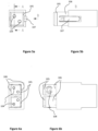
- FIG 1a and Figure 1b show schematically a 1-pair shielded and unshielded fixed connector 100 in detail.
- the connector 100 is part of a bipolar conductor connector system 1 and comprises a housing 101 configured as a shell made of a conductive material.
- the housing 101 works as a shield to minimise crosstalk to adjacent housings or other electrical or electronical parts.
- the two electrical contact elements 102 designed as two contact pins, connector contacts or poles of electrically conductive material, such as metal, are arranged.
- the contact pins 102 are separated from each other and this arrangement is protected against reversing poles.
- the contact pins 102 are accessible from the outside of the connector 100 so that a plug connector (not illustrated in the figures 1, 2 and 3 ) can be connected to the electrical contact elements 102.
- a plug connector not illustrated in the figures 1, 2 and 3
- these contact pins 102 Upon insertion of a corresponding plug connector, these contact pins 102 enter into electrical contacts configured as cylindrical holes in a holder 105.
- the holder 105 has two cylindrical holes disposed parallel to the longitudinal axis of the housing 101 and configured as electrical contacts 104, wherein the two contact pins 102 are situated in the holes.
- the plug connector can be plugged-in in only one single orientation.
- key means 103 are provided.
- the keying function is achieved by orientation and design of an abraded corner on the housing 101. Further forms and/or positions of the key means 103 are possible such as a groove or a ridge.
- the key means prevent insertion of the plug connector in a wrong orientation to avoid damage caused by inverted voltages.
- Figures 2a and 2b show schematically a 2-pair fixed connector, wherein two housings 101 are arranged next to each other. In each housing 101 two contact pins 102 are arranged. According to the key means configured as abraded corner in the upper left and right corners of the connector 100 up to two plug connectors can be plugged in in an unambiguous orientation.
- Figures 3a and 3b show schematically a 4-pair fixed connector, wherein four housings 101 are bundled forming a square with a centre. The abraded corners of each housing 101 are arranged on the outmost corners relative to the centre. This arrangement of fixed connectors allows to plug-in up to four plug connectors.
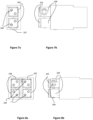
- FIGS 4a and 4b show schematically a free connector, referred as plug connector 105, configured as 1-pair plug connector 105 with a snap-in mechanism 108.
- the plug connector 105 has a holder 105a in which two electrical contacts 104 are provided as holes symmetrically. The symmetry results in best achievable signal transmission.
- the metallic housing acts as screen contact when connected to a fixed connector.
- the snap-in mechanism 108 comprises at two opposite sides of the holder elastically mounted or resilient snap elements such that the plug connector 105 is capable of snap-in fitting to a female housing of the corresponding connector 100.
- the snap elements can be configured as locking button with a protruding portion which serves as a locking means.
- the locking button can be configured as a distinct element from the holder 105a and can be snap-fitted to the connector housing when the protruding part is arranged in openings provided on the housing.
- FIGS 5a and 5b show schematically a free connector, referred as plug connector 105 designed as 1-pair plug connector with one locking mechanism 107.
- the plug connector 105 typically snap fits with the connector 100. Therefore, a latch or locking mechanism 107 is employed, such that when a latch is depressed the plug connector 105 is released from the push-fit connection with the connector. Applying pressure to the latch is quick and simple.
- the locking mechanism 107 comprises the latch 107a in order to engage to a locking part 107b provided at the corresponding part of the connector 100 to prevent the plug connector 105 from slipping off.
- the latch 107a can be pivotably attached by a resilient U-shaped strap and can be pushed traversed to the mating direction such to engage with the locking part 107b.
- Figures 6a and 6b show schematically a free connector, referred as plug connector 105 designed as 2-pair plug connector with a snap-in mechanism 108.
- plug connector 105 designed as 2-pair plug connector with a snap-in mechanism 108.
- key means 103 are provided as abraded edge compatible to the abraded corner provided in the housing 102 of the connector 100.
- the snap-in mechanism 108 of each protruding holder can differ in orientation from each other such that the snap-in mechanisms 108 is provided on two sides opposite to each other in horizontal orientation and in vertical orientation, respectively.
- Figures 7a and 7b show schematically a 2-pair plug connector 105 with an abraded edge on each holder and at least one locking mechanism 107 provided at one of the two plug connectors 105.
- Figures 8a and 8b show schematically a 4-pair plug connector 105 with a snap-in mechanism 108 at each of the four holder of the plug connector 105.
- Figures 9a and 9b show schematically a 4-pair plug connector 105 with one locking mechanism 107 at one of the four holder of the plug connectors 105 and snap-in mechanism 108 at the other of the four plug connectors 105.
Abstract
Bipolar conductor connector system (1) for Single Pair Ethernet applications comprising a fixed connector (100) with a housing (101) and electrical contact elements (102) and a free plug connector (105) with electrical contacts (104) configured for attachment to a Single Pair cable. The bipolar conductor connector system (1) further comprises key means (103) configured for an unambiguous plug-in of the free plug connector (105) in the fixed connector (100) in a predetermined orientation.
Description
- The present invention relates to a bipolar conductor connector system for electrical and mechanical connection of electrical conductors for electrical and electronic equipment, including shielded and unshielded, free and fixed connectors and plug connectors, in particular for Single Pair Ethernet, but not restricted to it.
- Single pair Ethernet (SPE) is gaining attention over automotive applications to industrial and building automation and other applications. It is considered to represent the next generation of communication architecture for example in smart factories and the Industrial Internet of Things (IIoT). The SPE technology delivers high-performance data and power transmission through a single-twisted pair instead of two or four twisted pairs of wires. Because of lower costs with SPE many applications can be more cost-effective and therefore attractive. Using SPE has the added advantage of being able to incorporate with other Ethernet protocols in use, allowing expansion while avoiding the need to rip and replace existing communications or adding complexity with gateways. Furthermore, not only the costs are reduced by installing less material but as well it is easier to extend an existing system than with eight-wire cables. With thinner and lighter cables, more Ethernet channels can be housed than before in existing cable runs to improve construction and size for new applications. Alternatively, bundles of 1-pair cables to 4-pair cables can be used to transmit efficiently up to 4 independent applications and split it at each end, also known as cable sharing.
- Another, particularly important feature of SPE is the possibility of supplying power to the connected peripherals via PoDL (Power over Data Line) parallel with data transmission. This allows to connect any device with only one cable providing data and power on the same interface. The addition of PoDL is an additional reason to use copper cabling at reduced costs. If power requirements exceed the specification, power can be run separately. But in most cases, there is no need to increase the amount of copper running a separate power cable for sensors and actors.
- The basis of SPE is the development of international standards for this technology. The physical properties and transfer rates are defined internationally by different standardisation bodies. Data transmission rates of 10 Mbit/s with a reach of 1000 m and up to 1 Gbit/s with a reach of 40 m to 100 m are adequate. In today's PoE applications, the power delivery to end devices requires up to 90 W at the power source equipment (PSE) on four pairs. With the PoDL technology the currently highest power level to be delivered to the powered device (PD) is 50 W with a maximum current of 1.579 A.
- Additionally, PoDL opens up further applications to SPE such as building infrastructure and/or production under extreme conditions with the advantage that the infrastructure is easy to install thanks to miniaturised connectors and single pair cables. SPE shows additional advantages such as thinner bending radii, smaller cables, and transmission rates up to 1 Gbit/s or higher on a single pair.
- Known from
EP 2 649 686 is a multipolar outlet for a conductor connector system with cable sharing capabilities as described in several European and international cabling standards which is suitable for frequencies up to 4000 MHz. The outlet comprises a housing, divided into at least two chambers which are separated from each other by a partition element. Each chamber has two contacts accessible from a first end of the chamber, wherein the contacts run through inserts parallel to the longitudinal axis of the housing. A separator for separating the conductor wires and for holding the wires in place is arranged to form an end piece for the chambers at a second end thereof, opposite the first end, wherein the contacts are arranged to be electrically connected to the wires when the separator is in place in the housing. - The connector general requirements for Single Pair Ethernet are defined in a parent standard, such that the general electrical requirements of the different interfaces are the same for all connectors of the specific series of standards. The mechanical mating information, pin assignment and additional requirements of each connector are standardised in detail specifications. These are varying in mating faces, named as well as interfaces, dimensions, and mechanical properties. Therefore, one object of the invention is to provide a bipolar conductor connector system for Single Pair Ethernet applications compliant to current and upcoming application standards provided by the Institute of Electrical and Electronics Engineers (IEEE) and other organisations. In particular, the bipolar conductor connector system is configured for electrical and electronic equipment, including shielded and unshielded, free and fixed connectors with up to 8 ways. The bipolar conductor connector provides a mechanical matching information described as a keying function.
- It is another object of the invention to provide a conductor connector system, including plugs and sockets referred as well as jacks which can be combined as 2-pair interfaces or 4-pair interfaces or other numbers of pairs.
- It is another object of the invention to provide a conductor connector system designed to allow high currents up to 4 A and above, combined with requirements below the Low Voltage Directive (LVD) limitations. The LVD requirements cover health and safety risks on electrical equipment operating with an input or output voltage between 50 to 1000 V for alternating current or 75 to 1500 V for direct current. Therefore, the LVD specifies electrical characteristics of electrical equipment for both consumer and professional usage such as cables, power supply units, etc. The power transmission over connectors and cables is yielded to stay always below these voltages.
- The unique combination of low to high data transmission rates with low to high power delivery rates and any combination thereof, provided by the bipolar conductor connector system of the invention make this system usable in many areas of homes, offices, industry and distributed building services.
- According to the invention, the bipolar conductor connector system comprises a connector with a housing and electrical contact elements and a plug connector with electrical contacts configured for attachment to a Single Pair Ethernet cable. The Single Pair Ethernet cable comprises a first transmission line and a second transmission line for conducting data and power. The connector and the plug connector comprise key means configured for an unambiguous plug-in of the plug connector in the connector in a predetermined orientation.
- The bipolar conductor connector system covers shielded and unshielded free and fixed multimedia connectors (MMC) for data transmission with frequencies up to 4000 MHz for the shielded version and up to 600 MHz for the unshielded version of connectors, both with a current-carrying capacity up to 8 ways.
- The connector of the bipolar conductor connector system can be used for Single Pair Ethernet (SPE) according to known standards such as IEEE standards but is not restricted to such a standardised use. In general, the connector is a device providing connection and disconnection to a suitable mating component. The plug connector can be defined as part of the connector system integral with or intended to be attached to a flexible cable.
- The connector comprises a housing. The housing can be formed from a hollow, rectangular shell made of a conductive material to minimise crosstalk. The front or contact surface of the housing is defined by the front surface of the shell, while the rear or termination surface of the housing is defined by the exposed rear surface of the shell. Top and bottom surfaces of the shell define upper and lower surfaces of the housing, respectively. The housing is typically made of a metallic material of high strength and heat resistance. Furthermore, each housing is designed as a shield to minimise crosstalk between adjacent housings and/or other electrical or electronical parts such as wire segments nearby. Therefore, the connector designed as a multimedia connector can be used to run independently applications on each pair without any disturbance from neighbour pairs due to improved crosstalk performance. The housing is configured to mate with the plug connector along a longitudinal mating axis.
- The connector provides two electrical contact elements, in particular a first electrical contact element and a second electrical contact element, accessible from a first end of the housing, wherein the contact elements are arranged to be electrically connected to the wire pair. The electrical contact elements can be designed as male or female contacts. The two electrical contact elements of each housing of the connector allow transmission of data and power.
- In one embodiment the first electrical contact element and the second electrical contact element of the connector can be designed as cylindrical contact pins, connector contacts or poles of electrically conductive material arranged symmetrically in the housing of the connector to achieve the required impedance. Advantageously, a cylindrical geometry of the electrical contacts provides a circular contact area which avoids contact area degradation. The nominal diameter of the electrical contact elements can be approximately 1 mm in order to allow transmission of higher currents.
- The housing for the 1-pair connector can be configured with an outer shape and size, referred as well as form factor, which is smaller than a quarter of the well-known and mostly used standardised connector such as RJ45 or similar connectors. Thereby, the 1-pair connector can be used for cable sharing with already installed structured cabling. The RJ45 is a specified cable termination, in particular a standardised networking interface, defining male and female connectors and pin assignments used for connection by an eight-wire connector.
- The plug connector comprises two electrical contacts. The two electrical contacts can be configured as being inserted into a holder of a non-conducting material for separating the electrical contacts from each other in a defined distance. The arrangement of the two contacts in the holder can be in a symmetrical manner such that the achievable symmetry for signal transmission is maximised. A symmetrical arrangement is most favourable for signal transmission due to less sensitivity to interference coupling to nearby wire lines. The holder as well referred as an insert, has two cylindrical through holes disposed parallel to the longitudinal axis of the housing and configured to hold the first electrical contact and the second electrical contact, respectively.
- In another embodiment of the invention, optionally a screen contact can be arranged to improve crosstalk. This is most favourable at higher frequencies, for higher noise environments and at higher data rates with noise constraints. Improved crosstalk is also required for an independent parallel operation in a 4-pair cabling system, known as cable sharing and all kind of bundling.
- The housing, the holder and the two electrical contact elements and two electrical contacts are arranged in such a manner to achieve a predeterminable impedance. Moreover, with the invention it is possible to keep the distance between different wires more or less constant throughout the longitudinal distance of the connector thereby leading to a constant impedance.
- The connector is configured to receive and hold the plug connector in place. The plug connector can be inserted into the connector and hold in position by a locking mechanism or a snap-in mechanism or a screw locking. These locks are configured to inhibit longitudinal movement of the mating components of the conductor connector system. Thereby providing a robust design, a reliable use, and an effortless operation. In a preferred embodiment with a plug connector combining two or four holders each with two electrical contacts one locking mechanism and multiple snap-in mechanism are provided such that the plug connector is easy to manage.
- The key means for the keying function are provided that the plug connector is securely retained and held in correct alignment in the connector. For some applications, especially power applications, the orientation of the plug connected relative to the connector is relevant. The key means avoid that the plug connector is plugged in in a wrong orientation and therefore avoid damage caused by inverted voltages. The key means can be designed as a mechanical interface or mating face such as a ridge or a groove provided on the housing of the connector with the purpose that the plug connector can only be inserted into the housing in a single orientation so that only the correct electrical contact elements come into contact with each other. In a preferred embodiment, the key means is provided as an abraded corner, positioned depending on the number of bundled connectors and depending, if the connector is designed as a fixed or a free connector.
- For shielded and unshielded fixed 1-pair connectors the abraded corner can be in the lower left corner, for 2-pair connectors the abraded corners can be the upper outside right and left corners and for 4-pair connectors the abraded corners can be arranged at the outmost positions relative to a centre of the arrangement of the 4-pair connectors forming a square.
- For shielded and unshielded free 1-pair connectors with snap-in or locking device the abraded corner can be positioned on the lower right corner. In the case of free 2-pair connectors the abraded corners can be arranged on the outer upper right and upper left corners. In the case of free 4-pair connectors the abraded corners can be arranged at the outmost positions relative to a centre of the arrangement of the 4-pair connectors forming a square.
- The bipolar connection system is based on a plain design, which combines the advantages of single plug connectors and bundled connectors in blocks in a very space-saving way. According to the invention, the connector can be provided in distinctive styles relating to the number of pairs, e.g., 1-pair, 2-pairs and 4-pairs.
- For example, a 2-pair connector might be used for daisy chain configurations of devices in order to interconnect one device to an adjacent device. Daisy chaining is known as an uncomplicated way to connect a network, wherein devices are connected in series and a message that is sent on the network travels down the chain from one device to the other. In some standards for daisy chain networks the type of cable used is specified. For example, a certain minimum standard is defined, and the cable has to be twisted in order to balance differential signals to reduce or eliminate the effect of interference.
- A 4-pair connector might be used for the design of digital ceiling or other outlet planning arrangements and can run on new or installed 4 pair cabling systems with up to four applications independently.
- Other features and advantages of the invention will become apparent from the following description of non-limiting exemplary embodiments, with reference to the appended drawings, in which:
-
Figure 1a is a schematical front view of a fixed connector configured as 1-pair connector according to one embodiment; -
Figure 1b is a schematical side view of a fixed connector configured as 1-pair connector; -
Figure 2a is a schematical front view of a fixed connector configured as 2-pair connector; -
Figure 2b is a schematical side view of a fixed connector configured as 2-pair connector; -
Figure 3a is a schematical front view of a fixed connector configured as 4-pair connector; -
Figure 3b is a schematical side view of a fixed connector configured as 4-pair connector; -
Figure 4a is a schematical front view of a free connector configured as 1-pair connector with a snap-in mechanism; -
Figure 4b is a schematical side view of a free connector configured as 1-pair connector with a snap-in mechanism; -
Figure 5a is a schematical front view of a free connector configured as 1-pair connector with a locking mechanism; -
Figure 5b is a schematical side view of a free connector configured as 1-pair connector with a locking mechanism; -
Figure 6a is a schematical front view of a free connector configured as 2-pair connector with a snap-in mechanism; -
Figure 6b is a schematical side view of a free connector configured as 2-pair connector with a snap-in mechanism; -
Figure 7a is a schematical front view of a free connector configured as 2-pair connector with a locking mechanism; -
Figure 7b is a schematical side view of a free connector configured as 2-pair connector with a locking mechanism; -
Figure 8a is a schematical front view of a free connector configured as 4-pair connector with a snap-in mechanism; -
Figure 8b is a schematical side view of a free connector configured as 4-pair connector with a snap-in mechanism; -
Figure 9a is a schematical front view of a free connector configured as 4-pair connector with a locking mechanism; and -
Figure 9b is a schematical side view of a free connector configured as 4-pair connector with a locking mechanism. -
Figure 1a and Figure 1b show schematically a 1-pair shielded and unshielded fixed connector 100 in detail. The connector 100 is part of a bipolar conductor connector system 1 and comprises ahousing 101 configured as a shell made of a conductive material. Thehousing 101 works as a shield to minimise crosstalk to adjacent housings or other electrical or electronical parts. - The two
electrical contact elements 102, designed as two contact pins, connector contacts or poles of electrically conductive material, such as metal, are arranged. The contact pins 102 are separated from each other and this arrangement is protected against reversing poles. In the operational state of the connector 100, the contact pins 102 are accessible from the outside of the connector 100 so that a plug connector (not illustrated in thefigures 1, 2 and3 ) can be connected to theelectrical contact elements 102. Upon insertion of a corresponding plug connector, these contact pins 102 enter into electrical contacts configured as cylindrical holes in aholder 105. - In one embodiment shown, the
holder 105 has two cylindrical holes disposed parallel to the longitudinal axis of thehousing 101 and configured aselectrical contacts 104, wherein the twocontact pins 102 are situated in the holes. - The plug connector can be plugged-in in only one single orientation. For this purpose, key means 103 are provided. In the
figures 1a and 1b the keying function is achieved by orientation and design of an abraded corner on thehousing 101. Further forms and/or positions of the key means 103 are possible such as a groove or a ridge. The key means prevent insertion of the plug connector in a wrong orientation to avoid damage caused by inverted voltages. -
Figures 2a and 2b show schematically a 2-pair fixed connector, wherein twohousings 101 are arranged next to each other. In eachhousing 101 twocontact pins 102 are arranged. According to the key means configured as abraded corner in the upper left and right corners of the connector 100 up to two plug connectors can be plugged in in an unambiguous orientation. -
Figures 3a and 3b show schematically a 4-pair fixed connector, wherein fourhousings 101 are bundled forming a square with a centre. The abraded corners of eachhousing 101 are arranged on the outmost corners relative to the centre. This arrangement of fixed connectors allows to plug-in up to four plug connectors. -
Figures 4a and 4b show schematically a free connector, referred asplug connector 105, configured as 1-pair plug connector 105 with a snap-inmechanism 108. Theplug connector 105 has a holder 105a in which twoelectrical contacts 104 are provided as holes symmetrically. The symmetry results in best achievable signal transmission. The metallic housing acts as screen contact when connected to a fixed connector. The snap-inmechanism 108 comprises at two opposite sides of the holder elastically mounted or resilient snap elements such that theplug connector 105 is capable of snap-in fitting to a female housing of the corresponding connector 100. For example, the snap elements can be configured as locking button with a protruding portion which serves as a locking means. The locking button can be configured as a distinct element from the holder 105a and can be snap-fitted to the connector housing when the protruding part is arranged in openings provided on the housing. -
Figures 5a and 5b show schematically a free connector, referred asplug connector 105 designed as 1-pair plug connector with onelocking mechanism 107. Theplug connector 105 typically snap fits with the connector 100. Therefore, a latch orlocking mechanism 107 is employed, such that when a latch is depressed theplug connector 105 is released from the push-fit connection with the connector. Applying pressure to the latch is quick and simple. Thelocking mechanism 107 comprises the latch 107a in order to engage to a locking part 107b provided at the corresponding part of the connector 100 to prevent theplug connector 105 from slipping off. The latch 107a can be pivotably attached by a resilient U-shaped strap and can be pushed traversed to the mating direction such to engage with the locking part 107b. -
Figures 6a and 6b show schematically a free connector, referred asplug connector 105 designed as 2-pair plug connector with a snap-inmechanism 108. To ensure the right orientation of the plug connector in the corresponding connector 100, key means 103 are provided as abraded edge compatible to the abraded corner provided in thehousing 102 of the connector 100. The snap-inmechanism 108 of each protruding holder can differ in orientation from each other such that the snap-inmechanisms 108 is provided on two sides opposite to each other in horizontal orientation and in vertical orientation, respectively. -
Figures 7a and 7b show schematically a 2-pair plug connector 105 with an abraded edge on each holder and at least onelocking mechanism 107 provided at one of the twoplug connectors 105. -
Figures 8a and 8b show schematically a 4-pair plug connector 105 with a snap-inmechanism 108 at each of the four holder of theplug connector 105. -
Figures 9a and 9b show schematically a 4-pair plug connector 105 with onelocking mechanism 107 at one of the four holder of theplug connectors 105 and snap-inmechanism 108 at the other of the fourplug connectors 105. - While the invention has been illustrated and described in detail in the drawings and foregoing description, such illustration and description are to be considered illustrative or exemplary and not restrictive, the invention being not limited to the disclosed embodiment. Other embodiments and variants are understood and can be achieved by those skilled in the art when conducting the claimed invention, based on a study of the drawings, the disclosure, and the appended claims. In particular the number of housings in the connector can be other than one, two or four.
Claims (15)
- A bipolar conductor connector system (1) for Single Pair Ethernet applications, but not restricted to it, comprising- a fixed connector (100) with a housing (101) and electrical contact elements (102), and- a free plug connector (105) with electrical contacts (104) configured for attachment to a Single Pair cable,characterised in that
the fixed connector (100) and the free plug connector (105) comprise key means (103) configured for an unambiguous plug-in of the free plug connector (105) in the fixed connector (100) in a predetermined orientation. - A bipolar conductor connector system (1) according to claim 1, wherein the housing (101) of the fixed connector (100) is made of a conductive material to minimise crosstalk between adjacent components.
- A bipolar conductor connector system (1) according to claims 1 or 2, wherein the housing (101) comprises two electrical contact elements (102) to provide data and power transmission.
- A bipolar conductor connector system (1) according to claim 3, wherein the two electrical contact elements (102) of the fixed connector (100) are configured as cylindrical contact pins arranged symmetrically in the housing (101).
- A bipolar conductor connector system (1) according to one of the preceding claims, wherein the housing (101) of the fixed connector (100) designed as a 1-pair connector has an outer form which is smaller than a quarter of the RJ45 standardised connector.
- A bipolar conductor connector system (1) according to one of the preceding claims, wherein the electrical contacts (104) of the free plug connector (105) are female electrical contacts (104) hold in a holder (105a).
- A bipolar conductor connector system (1) according to one of the preceding claims, wherein the key means (103) comprises matching faces configured on the fixed connector (100) and the free plug connector (105) such that the connection of them is possible only in one orientation.
- A bipolar conductor connector system (1) according to claim 7, wherein the matching faces are designed as abraded corner and abraded edge made in one predeterminable position.
- A bipolar conductor connector system (1) according to one of the preceding claims, wherein the position of the key means (103) varies depending on the number of combined housings (101).
- A bipolar conductor connector system (1) according to one of the preceding claims, wherein comprising a fixed connector (100) with one housing (101) for a 1-pair application, two housings (101) for up to 2 1-pair applications or four housings (101) for up to 4 1-pair applications.
- A bipolar conductor connector system (1) according to one of the preceding claims, wherein comprising a free plug connector (105) configured as 1-pair plug connector, 2-pair plug connector or 4-pair plug connector to be inserted in corresponding counter-piece fixed connectors (100).
- A bipolar conductor connector system (1) according to one of the preceding claims, wherein the free plug connector (105) provides at least one snap-in mechanism (108) capable of snap-in fitting to a corresponding fixed connector (100).
- A bipolar conductor connector system (1) according to one of the preceding claims, wherein the free plug connector (105) provides a locking mechanism (107).
- A bipolar conductor connector system (1) according to one of the preceding claims, wherein the free plug connector (105) comprises two holders (105a) each with two electrical contacts (104) to be insertable into a 2-pair fixed connector (100) or a 4-pair fixed connector (100) and hold in position via at least one snap-in mechanism (108).
- A bipolar conductor connector system (1) according to one of the claims 1 to 13, wherein the free plug connector (105) comprises four holders (105a) each with two electrical contacts (104) to be insertable into a fixed 4-pair connector (100) and hold in position via at least one locking mechanism (107).
Priority Applications (2)
| Application Number | Priority Date | Filing Date | Title |
|---|---|---|---|
| EP22181513.7A EP4300720A1 (en) | 2022-06-28 | 2022-06-28 | Bipolar connector system |
| PCT/EP2023/067346 WO2024002981A1 (en) | 2022-06-28 | 2023-06-26 | Bipolar connector system |
Applications Claiming Priority (1)
| Application Number | Priority Date | Filing Date | Title |
|---|---|---|---|
| EP22181513.7A EP4300720A1 (en) | 2022-06-28 | 2022-06-28 | Bipolar connector system |
Publications (1)
| Publication Number | Publication Date |
|---|---|
| EP4300720A1 true EP4300720A1 (en) | 2024-01-03 |
Family
ID=82385313
Family Applications (1)
| Application Number | Title | Priority Date | Filing Date |
|---|---|---|---|
| EP22181513.7A Pending EP4300720A1 (en) | 2022-06-28 | 2022-06-28 | Bipolar connector system |
Country Status (2)
| Country | Link |
|---|---|
| EP (1) | EP4300720A1 (en) |
| WO (1) | WO2024002981A1 (en) |
Citations (8)
| Publication number | Priority date | Publication date | Assignee | Title |
|---|---|---|---|---|
| EP0809331A1 (en) * | 1996-05-23 | 1997-11-26 | BKS Kabel-Service AG | Multipolar plug system having a socket with at least one plug for electrical and mechanical connection of electric conductors |
| US20060246780A1 (en) * | 2005-05-02 | 2006-11-02 | Tyco Electronics Corporation | Electrical connector with enhanced jack interface |
| EP2649686A1 (en) | 2010-12-06 | 2013-10-16 | BKS Engineering AG | Multipolar outlet for a conductor connector system |
| US20160218460A1 (en) * | 2013-07-11 | 2016-07-28 | Rosenberger Hochfrequenztechnik Gmbh & Co. Kg | System having a plurality of plug-in connectors and multiple plug-in connector |
| WO2020190758A1 (en) * | 2019-03-15 | 2020-09-24 | Commscope Technologies Llc | Connectors and contacts for a single twisted pair of conductors |
| WO2021067274A1 (en) * | 2019-09-30 | 2021-04-08 | Commscope Technologies Llc | Couplers for single pair connectors |
| DE102020106162A1 (en) * | 2020-03-06 | 2021-09-09 | Reichle & De-Massari Ag | Single-pair Ethernet device, single-pair Ethernet system, and method for installing a single-pair Ethernet system |
| US20220094092A1 (en) * | 2020-09-24 | 2022-03-24 | Avx Corporation | Solderless wire-to-board single pair ethernet connection system |
-
2022
- 2022-06-28 EP EP22181513.7A patent/EP4300720A1/en active Pending
-
2023
- 2023-06-26 WO PCT/EP2023/067346 patent/WO2024002981A1/en unknown
Patent Citations (8)
| Publication number | Priority date | Publication date | Assignee | Title |
|---|---|---|---|---|
| EP0809331A1 (en) * | 1996-05-23 | 1997-11-26 | BKS Kabel-Service AG | Multipolar plug system having a socket with at least one plug for electrical and mechanical connection of electric conductors |
| US20060246780A1 (en) * | 2005-05-02 | 2006-11-02 | Tyco Electronics Corporation | Electrical connector with enhanced jack interface |
| EP2649686A1 (en) | 2010-12-06 | 2013-10-16 | BKS Engineering AG | Multipolar outlet for a conductor connector system |
| US20160218460A1 (en) * | 2013-07-11 | 2016-07-28 | Rosenberger Hochfrequenztechnik Gmbh & Co. Kg | System having a plurality of plug-in connectors and multiple plug-in connector |
| WO2020190758A1 (en) * | 2019-03-15 | 2020-09-24 | Commscope Technologies Llc | Connectors and contacts for a single twisted pair of conductors |
| WO2021067274A1 (en) * | 2019-09-30 | 2021-04-08 | Commscope Technologies Llc | Couplers for single pair connectors |
| DE102020106162A1 (en) * | 2020-03-06 | 2021-09-09 | Reichle & De-Massari Ag | Single-pair Ethernet device, single-pair Ethernet system, and method for installing a single-pair Ethernet system |
| US20220094092A1 (en) * | 2020-09-24 | 2022-03-24 | Avx Corporation | Solderless wire-to-board single pair ethernet connection system |
Also Published As
| Publication number | Publication date |
|---|---|
| WO2024002981A1 (en) | 2024-01-04 |
Similar Documents
| Publication | Publication Date | Title |
|---|---|---|
| US10998685B2 (en) | Single pair ethernet connector system | |
| US8894296B2 (en) | Powered cat 5 plug and socket | |
| RU2406194C1 (en) | Adapter and plug-and-socket connection system | |
| US7316584B2 (en) | Matched impedance shielded pair interconnection system for high reliability applications | |
| CA2109998C (en) | Modular connector with contacts associated with more than one surface | |
| USRE41311E1 (en) | High frequency electrical connector | |
| US6083052A (en) | Enhanced performance connector | |
| US5639266A (en) | High frequency electrical connector | |
| KR0129984Y1 (en) | Electrical connector | |
| US6309255B1 (en) | Electrical connector having power contacts for providing high electrical power | |
| EP0939455A2 (en) | Low cross talk connector configuration | |
| EP2854229B1 (en) | Connector and method for its assembling | |
| US8062053B2 (en) | Electrical connector with offset latch | |
| EP2939314B1 (en) | Interface adapter | |
| US10571984B2 (en) | Communication node with digital plane interface | |
| US6206724B1 (en) | Combined connector for ethernet and modem cables | |
| CN217823361U (en) | Bus duct and power distribution system | |
| EP4300720A1 (en) | Bipolar connector system | |
| EP0142970A2 (en) | Electrical/lightwave connection arrangement | |
| CN112615212A (en) | Network socket with safety connector and magnetic element | |
| US7001221B2 (en) | Electrical signal connector | |
| US20220278489A1 (en) | Hybrid plug-in connector | |
| US6431922B1 (en) | Connector bearing high voltage | |
| CN116888839A (en) | Power socket module, power socket connector set and two-part electric coupling system | |
| CN112350119A (en) | Connector with a locking member |
Legal Events
| Date | Code | Title | Description |
|---|---|---|---|
| PUAI | Public reference made under article 153(3) epc to a published international application that has entered the european phase |
Free format text: ORIGINAL CODE: 0009012 |
|
| STAA | Information on the status of an ep patent application or granted ep patent |
Free format text: STATUS: THE APPLICATION HAS BEEN PUBLISHED |
|
| AK | Designated contracting states |
Kind code of ref document: A1 Designated state(s): AL AT BE BG CH CY CZ DE DK EE ES FI FR GB GR HR HU IE IS IT LI LT LU LV MC MK MT NL NO PL PT RO RS SE SI SK SM TR |