EP4300683A1 - Battery pack - Google Patents
Battery pack Download PDFInfo
- Publication number
- EP4300683A1 EP4300683A1 EP22759589.9A EP22759589A EP4300683A1 EP 4300683 A1 EP4300683 A1 EP 4300683A1 EP 22759589 A EP22759589 A EP 22759589A EP 4300683 A1 EP4300683 A1 EP 4300683A1
- Authority
- EP
- European Patent Office
- Prior art keywords
- battery pack
- casing
- protruding portion
- casing body
- core pack
- Prior art date
- Legal status (The legal status is an assumption and is not a legal conclusion. Google has not performed a legal analysis and makes no representation as to the accuracy of the status listed.)
- Granted
Links
Images


Classifications
-
- H—ELECTRICITY
- H01—ELECTRIC ELEMENTS
- H01M—PROCESSES OR MEANS, e.g. BATTERIES, FOR THE DIRECT CONVERSION OF CHEMICAL ENERGY INTO ELECTRICAL ENERGY
- H01M10/00—Secondary cells; Manufacture thereof
- H01M10/60—Heating or cooling; Temperature control
- H01M10/65—Means for temperature control structurally associated with the cells
- H01M10/655—Solid structures for heat exchange or heat conduction
-
- H—ELECTRICITY
- H01—ELECTRIC ELEMENTS
- H01M—PROCESSES OR MEANS, e.g. BATTERIES, FOR THE DIRECT CONVERSION OF CHEMICAL ENERGY INTO ELECTRICAL ENERGY
- H01M50/00—Constructional details or processes of manufacture of the non-active parts of electrochemical cells other than fuel cells, e.g. hybrid cells
- H01M50/20—Mountings; Secondary casings or frames; Racks, modules or packs; Suspension devices; Shock absorbers; Transport or carrying devices; Holders
- H01M50/204—Racks, modules or packs for multiple batteries or multiple cells
-
- H—ELECTRICITY
- H01—ELECTRIC ELEMENTS
- H01M—PROCESSES OR MEANS, e.g. BATTERIES, FOR THE DIRECT CONVERSION OF CHEMICAL ENERGY INTO ELECTRICAL ENERGY
- H01M50/00—Constructional details or processes of manufacture of the non-active parts of electrochemical cells other than fuel cells, e.g. hybrid cells
- H01M50/20—Mountings; Secondary casings or frames; Racks, modules or packs; Suspension devices; Shock absorbers; Transport or carrying devices; Holders
- H01M50/233—Mountings; Secondary casings or frames; Racks, modules or packs; Suspension devices; Shock absorbers; Transport or carrying devices; Holders characterised by physical properties of casings or racks, e.g. dimensions
- H01M50/242—Mountings; Secondary casings or frames; Racks, modules or packs; Suspension devices; Shock absorbers; Transport or carrying devices; Holders characterised by physical properties of casings or racks, e.g. dimensions adapted for protecting batteries against vibrations, collision impact or swelling
-
- H—ELECTRICITY
- H01—ELECTRIC ELEMENTS
- H01M—PROCESSES OR MEANS, e.g. BATTERIES, FOR THE DIRECT CONVERSION OF CHEMICAL ENERGY INTO ELECTRICAL ENERGY
- H01M50/00—Constructional details or processes of manufacture of the non-active parts of electrochemical cells other than fuel cells, e.g. hybrid cells
- H01M50/20—Mountings; Secondary casings or frames; Racks, modules or packs; Suspension devices; Shock absorbers; Transport or carrying devices; Holders
- H01M50/247—Mountings; Secondary casings or frames; Racks, modules or packs; Suspension devices; Shock absorbers; Transport or carrying devices; Holders specially adapted for portable devices, e.g. mobile phones, computers, hand tools or pacemakers
-
- H—ELECTRICITY
- H01—ELECTRIC ELEMENTS
- H01M—PROCESSES OR MEANS, e.g. BATTERIES, FOR THE DIRECT CONVERSION OF CHEMICAL ENERGY INTO ELECTRICAL ENERGY
- H01M50/00—Constructional details or processes of manufacture of the non-active parts of electrochemical cells other than fuel cells, e.g. hybrid cells
- H01M50/20—Mountings; Secondary casings or frames; Racks, modules or packs; Suspension devices; Shock absorbers; Transport or carrying devices; Holders
- H01M50/289—Mountings; Secondary casings or frames; Racks, modules or packs; Suspension devices; Shock absorbers; Transport or carrying devices; Holders characterised by spacing elements or positioning means within frames, racks or packs
- H01M50/291—Mountings; Secondary casings or frames; Racks, modules or packs; Suspension devices; Shock absorbers; Transport or carrying devices; Holders characterised by spacing elements or positioning means within frames, racks or packs characterised by their shape
-
- Y—GENERAL TAGGING OF NEW TECHNOLOGICAL DEVELOPMENTS; GENERAL TAGGING OF CROSS-SECTIONAL TECHNOLOGIES SPANNING OVER SEVERAL SECTIONS OF THE IPC; TECHNICAL SUBJECTS COVERED BY FORMER USPC CROSS-REFERENCE ART COLLECTIONS [XRACs] AND DIGESTS
- Y02—TECHNOLOGIES OR APPLICATIONS FOR MITIGATION OR ADAPTATION AGAINST CLIMATE CHANGE
- Y02E—REDUCTION OF GREENHOUSE GAS [GHG] EMISSIONS, RELATED TO ENERGY GENERATION, TRANSMISSION OR DISTRIBUTION
- Y02E60/00—Enabling technologies; Technologies with a potential or indirect contribution to GHG emissions mitigation
- Y02E60/10—Energy storage using batteries
Definitions
- the present invention relates to a core pack including a cell holder that holds cells.
- the present invention also relates to a battery pack including a casing that houses the core pack.
- WO 2019/230879 A1 discloses a battery pack including a core pack ("battery core pack" in WO 2019/230879 A1 ) and a casing.
- the core pack has a cell holder holding a plurality of unit cells.
- the core pack is housed in the casing.
- the core pack may include a heat dissipation sheet shown in FIG. 7 of International Publication No. WO 2019/230879 A1 , an insulating sheet, or the like. These sheets are interposed between the cell holder and the casing.
- the casing has a substantially rectangular parallelepiped shape as shown particularly in FIGS. 1 , 2 , and 4 of WO 2019/230879 A1 .
- the four side surfaces of the casing are substantially flat.
- a plurality of grooves are formed on the inner wall of the casing. Liquid such as water is guided by the grooves. Between adjacent grooves, protruding portions are provided that are raised relative to the grooves. As shown in FIG. 5 of WO 2019/230879 A1 , the protruding portions have a substantially square shape in plan view and extends toward the core pack.
- the reason why the heat dissipation sheet is housed in the casing is to quickly dissipate heat generated in the core pack to the outside of the casing when the unit cells are charged. There is a need for more rapid dissipation and more efficient removal of heat.
- a battery pack including a core pack including a cell holder holding a cell, and a casing housing the core pack,
- the inner wall of the casing is provided with the protruding portion protruding toward the outer wall of the cell holder housed in the casing.
- the protruding portion abuts the core pack including the cell holder. Therefore, when the core pack is heated, the heat is quickly transferred to the casing via the protruding portion. In other words, the heat of the core pack is quickly absorbed by the protruding portion. Therefore, the heat can be quickly removed from the core pack.
- the protruding portion functions as a rib portion that increases the rigidity of the casing. For this reason, the rigidity of the casing is ensured and thus the casing hardly deforms.
- a side wall portion facing the arch-shaped portion 24 is referred to as a "front surface portion”
- a side wall portion on a back surface thereof is referred to as a “back surface portion”
- side wall portions connected to the front surface portion and the back surface portion are referred to as a "left side portion” and a “right side portion”.
- these directions are provided only to simplify the explanation and facilitate understanding. These directions do not necessarily indicate direction or postures while the battery pack is discharged or charged.
- FIG. 1 is a schematic overall perspective view of a battery pack 10 according to the present embodiment.
- the battery pack 10 includes a bottom cover 12 and a casing 18.
- the casing 18 includes an elongated casing body 14 and a top cover 16.
- the casing body 14 is formed of a hollow body having a substantially quadrangular tubular shape with both ends in the longitudinal direction (height direction) opened. Both ends of the casing body 14 in the height direction are a lower end and an upper end in FIG. 1 .
- the bottom cover 12 closes the opening at a lower end of the casing body 14.
- the top cover 16 closes the opening at the upper end of the casing body 14.
- the top cover 16 is provided with an arch-shaped portion 24 and a tab-shaped portion 26 projecting from the upper surface.
- a grip bar 28 is provided from the arch-shaped portion 24 to the tab-shaped portion 26.
- the tab-shaped portion 26, the grip bar 28, and the arch-shaped portion 24 form a substantially H-shape.
- a cell holder 30 holding a plurality of unit cells (cells) is housed in the casing 18.
- the structure of the unit cells and of the cell holder 30 is known as described in detail in, for example, aforementioned WO 2019/230879 A1 (see in particular FIGS. 2 , 6, and 7) and will therefore not be described or illustrated in detail.
- Extension portions 32 are provided on outer walls of side surfaces of the cell holder 30 facing the front surface portion 14a and the back surface portion 14b of the casing body 14.
- the extension portions 32 protrude toward the inner wall of the casing body 14. Part of the extension portions 32 abuts each inner wall of the front surface portion 14a and the back surface portion 14b of the casing body 14. Because of this abutment, the cell holder 30 is positioned with respect to the casing 18.
- the cell holder 30 is provided with a hook portion 34.
- the hook portion 34 does not abut the front surface portion 14a.
- a harness 36 is hooked on the hook portion 34.
- the harness 36 connects a connector and a bus bar electrically connected to an electrode of the unit cell.
- the hook portion 34 may or may not abut the inside wall of the back surface portion 14b.
- the core pack 40 includes the cell holder 30, a heat transfer sheet 42 (heat dissipation sheet), and an insulating sheet 44.
- the cell holder 30, the heat transfer sheet 42, and the insulating sheet 44 are arranged in this order from the inner side to the outer side of the casing 18. That is, the cell holder 30 is surrounded by the heat transfer sheet 42.
- the heat transfer sheet 42 is surrounded by the insulating sheet 44.
- the heat transfer sheet 42 and the insulating sheet 44 are made of resin or the like, for example.
- the heat transfer sheet 42 and the insulating sheet 44 are soft and exhibit a certain degree of flexibility. However, the heat transfer sheet 42 is set thicker than the insulating sheet 44. Therefore, the rigidity of the heat transfer sheet 42 is greater than the rigidity of the insulating sheet 44.
- the heat transfer sheet 42 and the insulating sheet 44 are interposed between the cell holder 30 and the casing 18. Therefore, the extension portion 32 abuts the front surface portion 14a and the back surface portion 14b of the casing body 14 via the heat transfer sheet 42 and the insulating sheet 44. Similarly, the hook portion 34 abuts the back surface portion 14b in the same manner.
- the front surface portion 14a of the casing body 14 facing the arch-shaped portion 24 curves along the widthwise direction.
- the widthwise direction is a direction orthogonal to the longitudinal direction. That is, as shown in FIG. 2 , the front surface portion 14a gradually bulges as it goes from a widthwise end portion to a widthwise intermediate portion. For this reason, the front surface portion 14a is rounded. In this way, the front surface portion 14a bulges most outward at the widthwise-intermediate portion.
- the front surfaces of the bottom cover 12 and the top cover 16 may be not curved. However, it is preferable that the front surfaces of the bottom cover 12 and the top cover 16 curve in accordance with the front surface portion 14a. In this case, the design of the battery pack 10 further improves.
- the protruding lengths of the extension portions 32 facing the inner wall of the front surface portion 14a are different at the widthwise end portion and at the widthwise intermediate portion. Specifically, the protruding length of the extension portion 32 positioned at the widthwise end portion is smaller. On the contrary, the protruding length of the extension portion 32 positioned at the widthwise intermediate portion is larger. On the other hand, protruding distal end positions of the extension portion 32 and the hook portion 34 facing the inner surface of the back surface portion 14b are substantially the same.
- the left side portion 14c and the right side portion 14d of the casing body 14 are formed to be substantially flat as the back surface portion 14b.
- trapezoidal protruding portions 50 are provided, as a protruding portion, on the inner walls of the left side portion 14c and the right side portion 14d.
- the trapezoidal protruding portions 50 protrude toward the cell holder 30 or the core pack 40.
- the trapezoidal protruding portions 50 extend along the up-down direction that is the longitudinal direction of the casing body 14.
- the longitudinal dimension of the trapezoidal protruding portions 50 is smaller than the longitudinal dimension of the casing body 14.
- One end portion in the longitudinal direction and another end portion in the longitudinal direction of the trapezoidal protruding portion 50 are the lower end and the upper end of the trapezoidal protruding portion 50, respectively.
- One end portion and the other end portion in the longitudinal direction of the casing body 14 are a lower opening 20 and an upper opening 22 of the casing body 14, respectively. That is, one end portion in the longitudinal direction of the trapezoidal protruding portion 50 and one end portion in the longitudinal direction of the casing body 14 are end portions in the same direction. The same applies to the other end portion.
- the lower end of the trapezoidal protruding portion 50 is located above the lower opening 20 of the casing body 14.
- the upper end of the trapezoidal protruding portion 50 is located below the upper opening 22 of the casing body 14. That is, one end portion and the other end portion in the longitudinal direction of the trapezoidal protruding portion 50 are slightly closer to the center in the longitudinal direction than the openings of the casing body 14 are.
- a lower seal member 52 is disposed between the lower opening 20 and the lower end of the trapezoidal protruding portion 50.
- an upper seal member 54 is disposed between the upper end of the trapezoidal protruding portion 50 and the upper opening 22. In this way, one end portion and the other end portion in the longitudinal direction of the trapezoidal protruding portion 50 are separated from one end portion and the other end portion in the longitudinal direction of the casing body 14.
- an internal space capable of accommodating the seal members 52, 54 or the like is formed inside the casing 18.
- the lower end of the trapezoidal protruding portion 50 rises as it approaches the core pack 40.
- the lower end surface of the trapezoidal protruding portion 50 is an upward inclining surface 56 toward the upper end, which is the other end portion.
- the upper end of the trapezoidal protruding portion 50 is a downwardly inclining surface 58 toward the lower end, which is one end portion as it approaches the core pack 40.
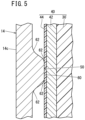
- FIG. 5 is an enlarged view of a principal part cut along a portion V surrounded by the circle in FIG. 2 .
- FIG. 5 is an enlarged view of a principal part when the casing body 14 is cut along the widthwise direction (direction from the front surface portion 14a toward the back surface portion 14b) orthogonal to the longitudinal direction.
- the width of the trapezoidal protruding portion 50 gradually decreases as it approaches the core pack 40. That is, the trapezoidal protruding portion 50 becomes wider as it is further away from the core pack 40 and approaches the inner wall of the left side portion 14c or the right side portion 14d.
- the protruding tip of the trapezoidal protruding portion 50 is formed as a flat surface 60 substantially parallel to the longitudinal direction of the left side portion 14c and the right side portion 14d.
- the flat surface 60 abuts the insulating sheet 44, the outermost part of the core pack 40.
- the corner portions of the protruding tip is formed as fillets. Therefore, the corner portion is called a curving portion 62.
- the corner portions of the skirt portions where the trapezoidal protruding portion 50 is continuous with the inner wall of the left side portion 14c or the right side portion 14d are formed as fillets. That is, these corner portions are also called the curving portions 62. All the curving portions 62 have a smooth surface on which no ridge line is formed.
- the battery pack 10 according to the present embodiment is basically configured as described above. Next, effects of the battery pack 10 will be described.
- the casing body 14 provided with the trapezoidal protruding portion 50 on the inner wall is manufactured by, for example, performing extrusion molding on a plate material made of aluminum alloy and suchlike.
- all corner portions of the trapezoidal protruding portion 50 are the curving portions 62. In this case, it is easier to release the casing body 14 than when the corner portion is not the curving portion 62. Therefore, the load on the molding die reduces.
- the outside of the cell holder 30 is surrounded by the heat transfer sheet 42. Thereafter, the outer side of the heat transfer sheet 42 is surrounded by the insulating sheet 44. Separately, the lower opening 20 of the casing body 14 is closed by the bottom cover 12.
- the lower seal member 52 is housed in the casing body 14.
- the lower opening 20 is closed by the bottom cover 12.
- the core pack 40 obtained as described above is inserted into the casing body 14.
- the downward inclining surface 58 serves as a guide for the core pack 40.
- the insulating sheet 44, the outermost part of the core pack 40 will abut the upper end, the corner portions, or the like of the trapezoidal protruding portion 50.
- the upper end of the trapezoidal protruding portion 50 is formed as the downward inclining surface 58 as described above.
- the corner portions of the trapezoidal protruding portion 50 are curving portions 62, which are rounded. Therefore, a sharp portion is prevented from coming into contact with or being caught by the insulating sheet 44 or the heat transfer sheet 42. Therefore, the insulating sheet 44 or the heat transfer sheet 42 is prevented from being damaged or broken.
- the insulating sheet 44 comes into sliding contact with the flat surface 60, which is the protruding tip of the trapezoidal protruding portion 50.
- the insulating sheet 44 is prevented from being caught by the corner portions during the sliding contact.
- the protruding tip of the trapezoidal protruding portion 50 is the flat surface 60, the insulating sheet 44 is prevented from being caught by the protruding tip. Therefore, the insulating sheet 44 or the heat transfer sheet 42 is prevented from being damaged or broken not only at the start of insertion of the core pack 40 but also in the middle of the insertion.
- the core pack 40 When the core pack 40 has been inserted to a predetermined depth, the core pack 40 is positioned and fixed in the casing body 14. Thereafter, the upper seal member 54 is housed in the casing body 14. Further, the upper opening 22 is closed by the top cover 16, and the top cover 16 is coupled to the casing body 14. In this way, the battery pack 10 is obtained.
- the lower seal member 52 seals between the bottom cover 12 and the casing body 14.
- the upper seal member 54 seals between the casing body 14 and the top cover 16.
- the front surface portion 14a of the casing body 14 is formed as a curving wall portion. Therefore, the design of the battery pack 10 improves. That is, the appearance of the battery pack 10 improves.
- the battery pack 10 is electrically connected to an external device.
- the battery pack 10 supplies power to the external device.
- the battery pack 10 discharges.
- the battery pack 10 is stored in a battery pack storage portion of the external device in an upright posture in which the longitudinal direction extends along the vertical direction.
- the battery pack 10 may take an inclined posture in which the longitudinal direction of the battery pack 10 inclines relative to the vertical direction.
- the battery pack 10 may be in a lying posture in which the longitudinal direction of the battery pack 10 extends along the horizontal direction.
- the battery pack 10 whose remaining capacity has decreased is taken out from the battery pack storage portion of the external device.
- the battery pack 10 is then stored in a battery pack storage portion of a charging device.
- the battery pack 10 takes any one of the standing posture, the inclined posture, or the lying posture.
- the trapezoidal protruding portion 50 is provided on the inner wall of the casing body 14. Since the trapezoidal protruding portion 50 serves as a rib portion, the rigidity of the casing body 14 is ensured. Therefore, deformation of the casing body 14 is prevented.
- the unit cells held by the cell holder 30 generate heat. Accordingly, the cell holder 30 accumulates heat. This heat is quickly absorbed by the heat transfer sheet 42. The heat is further transferred from the heat transfer sheet 42 to the trapezoidal protruding portion 50 via the insulating sheet 44.
- the trapezoidal protruding portion 50 is integrally formed with the casing body 14, and is made of aluminum alloy and suchlike as the casing body 14. Aluminum alloy is a good thermal conductor.
- the trapezoidal protruding portion 50 extends over a wide range in the vertical direction of the casing body 14, the contact area of the flat surface 60 of the trapezoidal protruding portion 50 with respect to the core pack 40 is large. For the reasons described above, the heat of the core pack 40 is quickly absorbed by the trapezoidal protruding portion 50.
- the trapezoidal protruding portion 50 has a shape that becomes wider as it is further away from the core pack 40. Therefore, heat transferred to the trapezoidal protruding portion 50 easily diffuses as it goes toward the left side portion 14c or the right side portion 14d. Accordingly, heat can be efficiently dispersed and thus heat can be efficiently transferred from the trapezoidal protruding portion 50 toward the left side portion 14c and the right side portion 14d.
- the casing body 14 is made of a good thermal conductor such as aluminum alloy, the heat of the core pack 40 absorbed by the trapezoidal protruding portion 50 quickly dissipates.
- the trapezoidal protruding portion 50 abutting the core pack 40 is provided on the inner wall of the casing 18, whereby it is possible to efficiently remove heat the core pack 40 accumulates can be efficiently removed.
- the rising inclining surface 56 serves as a guide for the core pack 40. Also at this removal, the insulating sheet 44 or the heat transfer sheet 42 is prevented from being damaged or broken for the same reasons as described above.
- the present invention is not limited to the embodiment described above, and various additional or modified structures may be adopted therein without departing from the essence and gist of the present invention.
- the outside of the cell holder 30 may be surrounded by the insulating sheet 44, and then the outside of the insulating sheet 44 may be surrounded by the heat transfer sheet 42.
- a waterproof sheet or the like may be further added to the core pack 40.
- the entire periphery of the cell holder 30 is covered with the insulating sheet 44.
- the plate-shaped insulating sheet may be interposed only between the side surface of the cell holder 30 facing the left side portion 14c or the right side portion 14d of the casing body 14 and the left side portion 14c or the right side portion 14d.
Landscapes
- Chemical & Material Sciences (AREA)
- Chemical Kinetics & Catalysis (AREA)
- Electrochemistry (AREA)
- General Chemical & Material Sciences (AREA)
- Engineering & Computer Science (AREA)
- Manufacturing & Machinery (AREA)
- Battery Mounting, Suspending (AREA)
- Secondary Cells (AREA)
Abstract
Description
- The present invention relates to a core pack including a cell holder that holds cells. The present invention also relates to a battery pack including a casing that houses the core pack.
-
WO 2019/230879 A1 discloses a battery pack including a core pack ("battery core pack" inWO 2019/230879 A1 ) and a casing. The core pack has a cell holder holding a plurality of unit cells. The core pack is housed in the casing. The core pack may include a heat dissipation sheet shown in FIG. 7 of International Publication No.WO 2019/230879 A1 , an insulating sheet, or the like. These sheets are interposed between the cell holder and the casing. - The casing has a substantially rectangular parallelepiped shape as shown particularly in
FIGS. 1 ,2 , and4 ofWO 2019/230879 A1 . The four side surfaces of the casing are substantially flat. A plurality of grooves are formed on the inner wall of the casing. Liquid such as water is guided by the grooves. Between adjacent grooves, protruding portions are provided that are raised relative to the grooves. As shown inFIG. 5 ofWO 2019/230879 A1 , the protruding portions have a substantially square shape in plan view and extends toward the core pack. - The reason why the heat dissipation sheet is housed in the casing is to quickly dissipate heat generated in the core pack to the outside of the casing when the unit cells are charged. There is a need for more rapid dissipation and more efficient removal of heat.
- It is a primary object of the present invention to provide a battery pack capable of efficiently removing heat from a core pack.
- According to an embodiment of the present invention, there is provided a battery pack including a core pack including a cell holder holding a cell, and a casing housing the core pack,
- a protruding portion that protrudes toward an outer wall of the cell holder is provided on an inner wall of the casing, and
- the protruding portion abuts the core pack.
- In the present invention, the inner wall of the casing is provided with the protruding portion protruding toward the outer wall of the cell holder housed in the casing. The protruding portion abuts the core pack including the cell holder. Therefore, when the core pack is heated, the heat is quickly transferred to the casing via the protruding portion. In other words, the heat of the core pack is quickly absorbed by the protruding portion. Therefore, the heat can be quickly removed from the core pack.
- In addition, the protruding portion functions as a rib portion that increases the rigidity of the casing. For this reason, the rigidity of the casing is ensured and thus the casing hardly deforms.
-
-
FIG. 1 is a schematic overall perspective view of a battery pack according to an embodiment of the present invention; -
FIG. 2 is a schematic cross-sectional view of the battery pack taken along a direction orthogonal to the longitudinal direction; -
FIG. 3 is a schematic overall perspective view of a casing body constituting the battery pack; -
FIG. 4 is a schematic front view of an inner surface side of a side wall of the casing body; and -
FIG. 5 is an enlarged view of a portion surrounded by a circle inFIG. 2 . - Hereinafter, preferred embodiments of a battery pack according to the present invention will be described in detail with reference to the accompanying drawings. In the following description, "down" and "up" correspond to the lower side and the upper side of each drawing. In addition, regarding a
casing 18, a side wall portion facing the arch-shaped portion 24 is referred to as a "front surface portion", a side wall portion on a back surface thereof is referred to as a "back surface portion", and side wall portions connected to the front surface portion and the back surface portion are referred to as a "left side portion" and a "right side portion". However, these directions are provided only to simplify the explanation and facilitate understanding. These directions do not necessarily indicate direction or postures while the battery pack is discharged or charged. -
FIG. 1 is a schematic overall perspective view of abattery pack 10 according to the present embodiment. Thebattery pack 10 includes abottom cover 12 and acasing 18. Thecasing 18 includes anelongated casing body 14 and atop cover 16. Thecasing body 14 is formed of a hollow body having a substantially quadrangular tubular shape with both ends in the longitudinal direction (height direction) opened. Both ends of thecasing body 14 in the height direction are a lower end and an upper end inFIG. 1 . Thebottom cover 12 closes the opening at a lower end of thecasing body 14. Thetop cover 16 closes the opening at the upper end of thecasing body 14. - The
top cover 16 is provided with an arch-shaped portion 24 and a tab-shaped portion 26 projecting from the upper surface. Agrip bar 28 is provided from the arch-shaped portion 24 to the tab-shaped portion 26. In a plan view in which thebattery pack 10 is viewed from the direction of thetop cover 16, the tab-shaped portion 26, thegrip bar 28, and the arch-shaped portion 24 form a substantially H-shape. - As shown in
FIG. 2 , acell holder 30 holding a plurality of unit cells (cells) is housed in thecasing 18. The structure of the unit cells and of thecell holder 30 is known as described in detail in, for example, aforementionedWO 2019/230879 A1 (see in particularFIGS. 2 , 6, and 7) and will therefore not be described or illustrated in detail. -
Extension portions 32 are provided on outer walls of side surfaces of thecell holder 30 facing thefront surface portion 14a and theback surface portion 14b of thecasing body 14. Theextension portions 32 protrude toward the inner wall of thecasing body 14. Part of theextension portions 32 abuts each inner wall of thefront surface portion 14a and theback surface portion 14b of thecasing body 14. Because of this abutment, thecell holder 30 is positioned with respect to thecasing 18. - Further, the
cell holder 30 is provided with ahook portion 34. Thehook portion 34 does not abut thefront surface portion 14a. Aharness 36 is hooked on thehook portion 34. Theharness 36 connects a connector and a bus bar electrically connected to an electrode of the unit cell. Thehook portion 34 may or may not abut the inside wall of theback surface portion 14b. - In the present embodiment, the
core pack 40 includes thecell holder 30, a heat transfer sheet 42 (heat dissipation sheet), and aninsulating sheet 44. Thecell holder 30, theheat transfer sheet 42, and theinsulating sheet 44 are arranged in this order from the inner side to the outer side of thecasing 18. That is, thecell holder 30 is surrounded by theheat transfer sheet 42. Theheat transfer sheet 42 is surrounded by the insulatingsheet 44. Theheat transfer sheet 42 and the insulatingsheet 44 are made of resin or the like, for example. Theheat transfer sheet 42 and the insulatingsheet 44 are soft and exhibit a certain degree of flexibility. However, theheat transfer sheet 42 is set thicker than the insulatingsheet 44. Therefore, the rigidity of theheat transfer sheet 42 is greater than the rigidity of the insulatingsheet 44. - The
heat transfer sheet 42 and the insulatingsheet 44 are interposed between thecell holder 30 and thecasing 18. Therefore, theextension portion 32 abuts thefront surface portion 14a and theback surface portion 14b of thecasing body 14 via theheat transfer sheet 42 and the insulatingsheet 44. Similarly, thehook portion 34 abuts theback surface portion 14b in the same manner. - The
front surface portion 14a of thecasing body 14 facing the arch-shapedportion 24 curves along the widthwise direction. The widthwise direction is a direction orthogonal to the longitudinal direction. That is, as shown inFIG. 2 , thefront surface portion 14a gradually bulges as it goes from a widthwise end portion to a widthwise intermediate portion. For this reason, thefront surface portion 14a is rounded. In this way, thefront surface portion 14a bulges most outward at the widthwise-intermediate portion. Thus, the appearance (design) of thebattery pack 10 improves. The front surfaces of thebottom cover 12 and thetop cover 16 may be not curved. However, it is preferable that the front surfaces of thebottom cover 12 and thetop cover 16 curve in accordance with thefront surface portion 14a. In this case, the design of thebattery pack 10 further improves. - Since the
front surface portion 14a curves as described above, the protruding lengths of theextension portions 32 facing the inner wall of thefront surface portion 14a are different at the widthwise end portion and at the widthwise intermediate portion. Specifically, the protruding length of theextension portion 32 positioned at the widthwise end portion is smaller. On the contrary, the protruding length of theextension portion 32 positioned at the widthwise intermediate portion is larger. On the other hand, protruding distal end positions of theextension portion 32 and thehook portion 34 facing the inner surface of theback surface portion 14b are substantially the same. - The
left side portion 14c and theright side portion 14d of thecasing body 14 are formed to be substantially flat as theback surface portion 14b. As shown inFIGS. 2 and3 , trapezoidal protrudingportions 50 are provided, as a protruding portion, on the inner walls of theleft side portion 14c and theright side portion 14d. Thetrapezoidal protruding portions 50 protrude toward thecell holder 30 or thecore pack 40. In this case, thetrapezoidal protruding portions 50 extend along the up-down direction that is the longitudinal direction of thecasing body 14. However, the longitudinal dimension of thetrapezoidal protruding portions 50 is smaller than the longitudinal dimension of thecasing body 14. - One end portion in the longitudinal direction and another end portion in the longitudinal direction of the
trapezoidal protruding portion 50 are the lower end and the upper end of thetrapezoidal protruding portion 50, respectively. One end portion and the other end portion in the longitudinal direction of thecasing body 14 are alower opening 20 and anupper opening 22 of thecasing body 14, respectively. That is, one end portion in the longitudinal direction of thetrapezoidal protruding portion 50 and one end portion in the longitudinal direction of thecasing body 14 are end portions in the same direction. The same applies to the other end portion. The lower end of thetrapezoidal protruding portion 50 is located above thelower opening 20 of thecasing body 14. The upper end of thetrapezoidal protruding portion 50 is located below theupper opening 22 of thecasing body 14. That is, one end portion and the other end portion in the longitudinal direction of thetrapezoidal protruding portion 50 are slightly closer to the center in the longitudinal direction than the openings of thecasing body 14 are. - For example, a
lower seal member 52 is disposed between thelower opening 20 and the lower end of thetrapezoidal protruding portion 50. Similarly, for example, anupper seal member 54 is disposed between the upper end of thetrapezoidal protruding portion 50 and theupper opening 22. In this way, one end portion and the other end portion in the longitudinal direction of thetrapezoidal protruding portion 50 are separated from one end portion and the other end portion in the longitudinal direction of thecasing body 14. Thus, an internal space capable of accommodating theseal members casing 18. - No irregularities are formed on the inner wall of the
casing body 14 between thelower opening 20 and the lower end of thetrapezoidal protruding portion 50 and between the upper end of thetrapezoidal protruding portion 50 and theupper opening 22. Therefore, thelower seal member 52 and theupper seal member 54 can be brought into close contact with the inner wall of thecasing body 14. Thus, the sealing performance is ensured. - As shown in
FIGS. 3 and4 , the lower end of thetrapezoidal protruding portion 50 rises as it approaches thecore pack 40. In other words, the lower end surface of thetrapezoidal protruding portion 50 is anupward inclining surface 56 toward the upper end, which is the other end portion. On the other hand, the upper end of thetrapezoidal protruding portion 50 is a downwardly incliningsurface 58 toward the lower end, which is one end portion as it approaches thecore pack 40. -
FIG. 5 is an enlarged view of a principal part cut along a portion V surrounded by the circle inFIG. 2 . In other words,FIG. 5 is an enlarged view of a principal part when thecasing body 14 is cut along the widthwise direction (direction from thefront surface portion 14a toward theback surface portion 14b) orthogonal to the longitudinal direction. As shown inFIG. 5 , the width of thetrapezoidal protruding portion 50 gradually decreases as it approaches thecore pack 40. That is, thetrapezoidal protruding portion 50 becomes wider as it is further away from thecore pack 40 and approaches the inner wall of theleft side portion 14c or theright side portion 14d. - Further, the protruding tip of the
trapezoidal protruding portion 50, the narrowest part, is formed as aflat surface 60 substantially parallel to the longitudinal direction of theleft side portion 14c and theright side portion 14d. Theflat surface 60 abuts the insulatingsheet 44, the outermost part of thecore pack 40. The corner portions of the protruding tip is formed as fillets. Therefore, the corner portion is called a curvingportion 62. Similarly, the corner portions of the skirt portions where thetrapezoidal protruding portion 50 is continuous with the inner wall of theleft side portion 14c or theright side portion 14d are formed as fillets. That is, these corner portions are also called the curvingportions 62. All the curvingportions 62 have a smooth surface on which no ridge line is formed. - The
battery pack 10 according to the present embodiment is basically configured as described above. Next, effects of thebattery pack 10 will be described. - First, the
casing body 14 provided with thetrapezoidal protruding portion 50 on the inner wall is manufactured by, for example, performing extrusion molding on a plate material made of aluminum alloy and suchlike. In the present embodiment, all corner portions of thetrapezoidal protruding portion 50 are the curvingportions 62. In this case, it is easier to release thecasing body 14 than when the corner portion is not the curvingportion 62. Therefore, the load on the molding die reduces. - When the
battery pack 10 is assembled, the outside of thecell holder 30 is surrounded by theheat transfer sheet 42. Thereafter, the outer side of theheat transfer sheet 42 is surrounded by the insulatingsheet 44. Separately, thelower opening 20 of thecasing body 14 is closed by thebottom cover 12. - Next, the
lower seal member 52 is housed in thecasing body 14. Thelower opening 20 is closed by thebottom cover 12. Thereafter, thecore pack 40 obtained as described above is inserted into thecasing body 14. At this time, the downward incliningsurface 58 serves as a guide for thecore pack 40. Here, it is expected that the insulatingsheet 44, the outermost part of thecore pack 40, will abut the upper end, the corner portions, or the like of thetrapezoidal protruding portion 50. - The upper end of the
trapezoidal protruding portion 50 is formed as thedownward inclining surface 58 as described above. The corner portions of thetrapezoidal protruding portion 50 are curvingportions 62, which are rounded. Therefore, a sharp portion is prevented from coming into contact with or being caught by the insulatingsheet 44 or theheat transfer sheet 42. Therefore, the insulatingsheet 44 or theheat transfer sheet 42 is prevented from being damaged or broken. - While the
core pack 40 is being inserted into thecasing body 14, the insulatingsheet 44 comes into sliding contact with theflat surface 60, which is the protruding tip of thetrapezoidal protruding portion 50. As described above, since the corner portions of thetrapezoidal protruding portion 50 is the curvingportion 62, the insulatingsheet 44 is prevented from being caught by the corner portions during the sliding contact. Further, since the protruding tip of thetrapezoidal protruding portion 50 is theflat surface 60, the insulatingsheet 44 is prevented from being caught by the protruding tip. Therefore, the insulatingsheet 44 or theheat transfer sheet 42 is prevented from being damaged or broken not only at the start of insertion of thecore pack 40 but also in the middle of the insertion. - When the
core pack 40 has been inserted to a predetermined depth, thecore pack 40 is positioned and fixed in thecasing body 14. Thereafter, theupper seal member 54 is housed in thecasing body 14. Further, theupper opening 22 is closed by thetop cover 16, and thetop cover 16 is coupled to thecasing body 14. In this way, thebattery pack 10 is obtained. Thelower seal member 52 seals between thebottom cover 12 and thecasing body 14. Theupper seal member 54 seals between thecasing body 14 and thetop cover 16. - As shown in
FIG. 1 , thefront surface portion 14a of thecasing body 14 is formed as a curving wall portion. Therefore, the design of thebattery pack 10 improves. That is, the appearance of thebattery pack 10 improves. - In the
casing 18, theflat surface 60 of thetrapezoidal protruding portion 50 is in contact with thecell holder 30 via the insulatingsheet 44 and theheat transfer sheet 42. In this state, thebattery pack 10 is electrically connected to an external device. Thebattery pack 10 supplies power to the external device. In other words, thebattery pack 10 discharges. At this time, for example, thebattery pack 10 is stored in a battery pack storage portion of the external device in an upright posture in which the longitudinal direction extends along the vertical direction. Alternatively, thebattery pack 10 may take an inclined posture in which the longitudinal direction of thebattery pack 10 inclines relative to the vertical direction. Thebattery pack 10 may be in a lying posture in which the longitudinal direction of thebattery pack 10 extends along the horizontal direction. - The
battery pack 10 whose remaining capacity has decreased is taken out from the battery pack storage portion of the external device. Thebattery pack 10 is then stored in a battery pack storage portion of a charging device. Similarly to the above, in this case, thebattery pack 10 takes any one of the standing posture, the inclined posture, or the lying posture. - When the
battery pack 10 is removed from the battery pack storage portion or when thebattery pack 10 is stored in the battery pack storage portion in this way, it is expected that thecasing 18, particularly thecasing body 14, will come into contact with objects. However, thetrapezoidal protruding portion 50 is provided on the inner wall of thecasing body 14. Since thetrapezoidal protruding portion 50 serves as a rib portion, the rigidity of thecasing body 14 is ensured. Therefore, deformation of thecasing body 14 is prevented. - Especially during charging, the unit cells held by the
cell holder 30 generate heat. Accordingly, thecell holder 30 accumulates heat. This heat is quickly absorbed by theheat transfer sheet 42. The heat is further transferred from theheat transfer sheet 42 to thetrapezoidal protruding portion 50 via the insulatingsheet 44. Thetrapezoidal protruding portion 50 is integrally formed with thecasing body 14, and is made of aluminum alloy and suchlike as thecasing body 14. Aluminum alloy is a good thermal conductor. In addition, since thetrapezoidal protruding portion 50 extends over a wide range in the vertical direction of thecasing body 14, the contact area of theflat surface 60 of thetrapezoidal protruding portion 50 with respect to thecore pack 40 is large. For the reasons described above, the heat of thecore pack 40 is quickly absorbed by thetrapezoidal protruding portion 50. - The
trapezoidal protruding portion 50 has a shape that becomes wider as it is further away from thecore pack 40. Therefore, heat transferred to thetrapezoidal protruding portion 50 easily diffuses as it goes toward theleft side portion 14c or theright side portion 14d. Accordingly, heat can be efficiently dispersed and thus heat can be efficiently transferred from thetrapezoidal protruding portion 50 toward theleft side portion 14c and theright side portion 14d. - Heat that has reached the
left side portion 14c or theright side portion 14d dissipates from theleft side portion 14c or theright side portion 14d to the atmosphere. Since thecasing body 14 is made of a good thermal conductor such as aluminum alloy, the heat of thecore pack 40 absorbed by thetrapezoidal protruding portion 50 quickly dissipates. As described above, thetrapezoidal protruding portion 50 abutting thecore pack 40 is provided on the inner wall of thecasing 18, whereby it is possible to efficiently remove heat thecore pack 40 accumulates can be efficiently removed. - When the
core pack 40 is removed from thecasing 18 for maintenance or the like, the risinginclining surface 56 serves as a guide for thecore pack 40. Also at this removal, the insulatingsheet 44 or theheat transfer sheet 42 is prevented from being damaged or broken for the same reasons as described above. - The present invention is not limited to the embodiment described above, and various additional or modified structures may be adopted therein without departing from the essence and gist of the present invention.
- For example, the outside of the
cell holder 30 may be surrounded by the insulatingsheet 44, and then the outside of the insulatingsheet 44 may be surrounded by theheat transfer sheet 42. As described inWO 2019/230879 A1 , a waterproof sheet or the like may be further added to thecore pack 40. - In this embodiment, the entire periphery of the
cell holder 30 is covered with the insulatingsheet 44. On the other hand, the plate-shaped insulating sheet may be interposed only between the side surface of thecell holder 30 facing theleft side portion 14c or theright side portion 14d of thecasing body 14 and theleft side portion 14c or theright side portion 14d.
Claims (7)
- A battery pack (10) comprising:a core pack (40) that includes a cell holder (30) holding a cell; anda casing (18) that houses the core pack,whereinan inner wall of the casing is provided with a protruding portion (50) that protrudes toward an outer wall of the cell holder, andthe protruding portion abuts the core pack.
- The battery pack according to claim 1, wherein the protruding portion extends along a longitudinal direction of the casing.
- The battery pack according to claim 2, wherein one end portion of the protruding portion in the longitudinal direction is an inclining surface (56) inclining toward another end portion in the longitudinal direction.
- The battery pack according to claim 2 or 3, whereina longitudinal dimension of the protruding portion is smaller than a longitudinal dimension of the casing, andan end portion of the protruding portion in the longitudinal direction is disposed at a position away from an end portion of the casing in the longitudinal direction.
- The battery pack according to any one of claims 1 to 4, wherein the protruding portion becomes wider as the protruding portion is further away from the core pack.
- The battery pack according to claim 5, wherein a corner portion of the protruding portion is a curving portion (62) .
- The battery pack according to any one of claims 1 to 6, wherein a portion of the protruding portion that abuts the core pack is a flat surface.
Applications Claiming Priority (2)
| Application Number | Priority Date | Filing Date | Title |
|---|---|---|---|
| JP2021028717 | 2021-02-25 | ||
| PCT/JP2022/006999 WO2022181553A1 (en) | 2021-02-25 | 2022-02-21 | Battery pack |
Publications (4)
| Publication Number | Publication Date |
|---|---|
| EP4300683A1 true EP4300683A1 (en) | 2024-01-03 |
| EP4300683A4 EP4300683A4 (en) | 2024-10-30 |
| EP4300683C0 EP4300683C0 (en) | 2025-11-26 |
| EP4300683B1 EP4300683B1 (en) | 2025-11-26 |
Family
ID=83048086
Family Applications (1)
| Application Number | Title | Priority Date | Filing Date |
|---|---|---|---|
| EP22759589.9A Active EP4300683B1 (en) | 2021-02-25 | 2022-02-21 | Battery pack |
Country Status (4)
| Country | Link |
|---|---|
| US (1) | US20240234922A9 (en) |
| EP (1) | EP4300683B1 (en) |
| JP (1) | JP7554901B2 (en) |
| WO (1) | WO2022181553A1 (en) |
Families Citing this family (2)
| Publication number | Priority date | Publication date | Assignee | Title |
|---|---|---|---|---|
| USD938904S1 (en) * | 2018-12-27 | 2021-12-21 | Neutron Holdings, Inc. | Battery |
| USD1100813S1 (en) * | 2023-07-21 | 2025-11-04 | Shenzhen Poweroak Newener Co., Ltd | Battery pack |
Family Cites Families (7)
| Publication number | Priority date | Publication date | Assignee | Title |
|---|---|---|---|---|
| DE102009012183A1 (en) * | 2009-02-27 | 2010-09-02 | Andreas Stihl Ag & Co. Kg | Battery pack for a hand-held implement |
| JP6136230B2 (en) * | 2012-01-16 | 2017-05-31 | 株式会社Gsユアサ | Battery pack and power supply device |
| JP6227420B2 (en) * | 2014-01-09 | 2017-11-08 | 株式会社マキタ | Battery pack for electric tools |
| JP6805705B2 (en) * | 2016-10-12 | 2020-12-23 | 株式会社Gsユアサ | Power storage device |
| JP7307721B2 (en) * | 2018-05-24 | 2023-07-12 | 本田技研工業株式会社 | battery pack |
| JP6870156B2 (en) * | 2018-05-30 | 2021-05-12 | 本田技研工業株式会社 | Battery pack |
| KR102366507B1 (en) * | 2018-06-26 | 2022-02-22 | 주식회사 엘지에너지솔루션 | Battery pack and vehicle comprising the same |
-
2022
- 2022-02-21 JP JP2023502400A patent/JP7554901B2/en active Active
- 2022-02-21 EP EP22759589.9A patent/EP4300683B1/en active Active
- 2022-02-21 US US18/547,548 patent/US20240234922A9/en active Pending
- 2022-02-21 WO PCT/JP2022/006999 patent/WO2022181553A1/en not_active Ceased
Also Published As
| Publication number | Publication date |
|---|---|
| WO2022181553A1 (en) | 2022-09-01 |
| JPWO2022181553A1 (en) | 2022-09-01 |
| EP4300683A4 (en) | 2024-10-30 |
| EP4300683C0 (en) | 2025-11-26 |
| US20240234922A9 (en) | 2024-07-11 |
| US20240136643A1 (en) | 2024-04-25 |
| EP4300683B1 (en) | 2025-11-26 |
| JP7554901B2 (en) | 2024-09-20 |
Similar Documents
| Publication | Publication Date | Title |
|---|---|---|
| EP4300683A1 (en) | Battery pack | |
| US11658358B2 (en) | Pouch case, and secondary battery and secondary battery pack using the same | |
| KR102311075B1 (en) | Battery Pack Having Pack Housing | |
| RU2516292C2 (en) | Accumulator battery and hand-held machine equipped with same | |
| US9172068B2 (en) | Battery pack | |
| CN102208783B (en) | Junction box | |
| US9935298B2 (en) | Battery cell case having front case plate seated into rear case plate | |
| KR102345048B1 (en) | Secondary Battery Pack Having Radiant Heat Plate | |
| US20180048033A1 (en) | Cartridge and battery module having same | |
| US10992008B2 (en) | Drawer-type battery pack | |
| JP7074416B2 (en) | Battery unit | |
| US20250357595A1 (en) | Power tool and battery pack for use with the same | |
| JP2010277796A (en) | Pack battery | |
| CN210468224U (en) | Electrical connector | |
| JP5107810B2 (en) | Battery holder | |
| JP2001084981A (en) | Sealed lead-acid battery | |
| KR20200052676A (en) | Battery Module | |
| KR101993821B1 (en) | A battery pack with a case easy to dissipate | |
| JP2021136164A (en) | Busbar module | |
| US20070145098A1 (en) | Can and lithium secondary battery using the same | |
| CN223052261U (en) | Battery box with good heat dissipation performance | |
| CN110299477A (en) | The manufacturing method of battery module and battery module | |
| CN213212225U (en) | Lithium battery packaging structure and lithium battery | |
| KR102120932B1 (en) | Secondary battery module improved in cooling fin disposition structure and cooling fin assembly for the same | |
| KR102787769B1 (en) | Battery cell |
Legal Events
| Date | Code | Title | Description |
|---|---|---|---|
| STAA | Information on the status of an ep patent application or granted ep patent |
Free format text: STATUS: THE INTERNATIONAL PUBLICATION HAS BEEN MADE |
|
| PUAI | Public reference made under article 153(3) epc to a published international application that has entered the european phase |
Free format text: ORIGINAL CODE: 0009012 |
|
| STAA | Information on the status of an ep patent application or granted ep patent |
Free format text: STATUS: REQUEST FOR EXAMINATION WAS MADE |
|
| 17P | Request for examination filed |
Effective date: 20230920 |
|
| AK | Designated contracting states |
Kind code of ref document: A1 Designated state(s): AL AT BE BG CH CY CZ DE DK EE ES FI FR GB GR HR HU IE IS IT LI LT LU LV MC MK MT NL NO PL PT RO RS SE SI SK SM TR |
|
| DAV | Request for validation of the european patent (deleted) | ||
| DAX | Request for extension of the european patent (deleted) | ||
| A4 | Supplementary search report drawn up and despatched |
Effective date: 20241001 |
|
| RIC1 | Information provided on ipc code assigned before grant |
Ipc: H01M 50/291 20210101ALI20240925BHEP Ipc: H01M 10/6554 20140101ALI20240925BHEP Ipc: H01M 10/655 20140101ALI20240925BHEP Ipc: H01M 10/613 20140101ALI20240925BHEP Ipc: H01M 50/242 20210101AFI20240925BHEP |
|
| GRAP | Despatch of communication of intention to grant a patent |
Free format text: ORIGINAL CODE: EPIDOSNIGR1 |
|
| STAA | Information on the status of an ep patent application or granted ep patent |
Free format text: STATUS: GRANT OF PATENT IS INTENDED |
|
| RAP3 | Party data changed (applicant data changed or rights of an application transferred) |
Owner name: HONDA MOTOR CO., LTD. |
|
| INTG | Intention to grant announced |
Effective date: 20250709 |
|
| GRAS | Grant fee paid |
Free format text: ORIGINAL CODE: EPIDOSNIGR3 |
|
| GRAA | (expected) grant |
Free format text: ORIGINAL CODE: 0009210 |
|
| STAA | Information on the status of an ep patent application or granted ep patent |
Free format text: STATUS: THE PATENT HAS BEEN GRANTED |
|
| AK | Designated contracting states |
Kind code of ref document: B1 Designated state(s): AL AT BE BG CH CY CZ DE DK EE ES FI FR GB GR HR HU IE IS IT LI LT LU LV MC MK MT NL NO PL PT RO RS SE SI SK SM TR |
|
| REG | Reference to a national code |
Ref country code: CH Ref legal event code: F10 Free format text: ST27 STATUS EVENT CODE: U-0-0-F10-F00 (AS PROVIDED BY THE NATIONAL OFFICE) Effective date: 20251126 Ref country code: GB Ref legal event code: FG4D |
|
| REG | Reference to a national code |
Ref country code: IE Ref legal event code: FG4D |
|
| U01 | Request for unitary effect filed |
Effective date: 20251126 |
|
| U07 | Unitary effect registered |
Designated state(s): AT BE BG DE DK EE FI FR IT LT LU LV MT NL PT RO SE SI Effective date: 20251202 |
|
| U20 | Renewal fee for the european patent with unitary effect paid |
Year of fee payment: 5 Effective date: 20260123 |
|
| PG25 | Lapsed in a contracting state [announced via postgrant information from national office to epo] |
Ref country code: ES Free format text: LAPSE BECAUSE OF FAILURE TO SUBMIT A TRANSLATION OF THE DESCRIPTION OR TO PAY THE FEE WITHIN THE PRESCRIBED TIME-LIMIT Effective date: 20251126 |
|
| PG25 | Lapsed in a contracting state [announced via postgrant information from national office to epo] |
Ref country code: NO Free format text: LAPSE BECAUSE OF FAILURE TO SUBMIT A TRANSLATION OF THE DESCRIPTION OR TO PAY THE FEE WITHIN THE PRESCRIBED TIME-LIMIT Effective date: 20260226 |
|
| PG25 | Lapsed in a contracting state [announced via postgrant information from national office to epo] |
Ref country code: HR Free format text: LAPSE BECAUSE OF FAILURE TO SUBMIT A TRANSLATION OF THE DESCRIPTION OR TO PAY THE FEE WITHIN THE PRESCRIBED TIME-LIMIT Effective date: 20251126 |
|
| PG25 | Lapsed in a contracting state [announced via postgrant information from national office to epo] |
Ref country code: RS Free format text: LAPSE BECAUSE OF FAILURE TO SUBMIT A TRANSLATION OF THE DESCRIPTION OR TO PAY THE FEE WITHIN THE PRESCRIBED TIME-LIMIT Effective date: 20260226 |
|
| PG25 | Lapsed in a contracting state [announced via postgrant information from national office to epo] |
Ref country code: IS Free format text: LAPSE BECAUSE OF FAILURE TO SUBMIT A TRANSLATION OF THE DESCRIPTION OR TO PAY THE FEE WITHIN THE PRESCRIBED TIME-LIMIT Effective date: 20260326 |
|
| PG25 | Lapsed in a contracting state [announced via postgrant information from national office to epo] |
Ref country code: PL Free format text: LAPSE BECAUSE OF FAILURE TO SUBMIT A TRANSLATION OF THE DESCRIPTION OR TO PAY THE FEE WITHIN THE PRESCRIBED TIME-LIMIT Effective date: 20251126 |