EP4300655A1 - Battery pack - Google Patents
Battery pack Download PDFInfo
- Publication number
- EP4300655A1 EP4300655A1 EP22193048.0A EP22193048A EP4300655A1 EP 4300655 A1 EP4300655 A1 EP 4300655A1 EP 22193048 A EP22193048 A EP 22193048A EP 4300655 A1 EP4300655 A1 EP 4300655A1
- Authority
- EP
- European Patent Office
- Prior art keywords
- battery
- monitoring unit
- disposed
- installation bracket
- battery monitoring
- Prior art date
- Legal status (The legal status is an assumption and is not a legal conclusion. Google has not performed a legal analysis and makes no representation as to the accuracy of the status listed.)
- Pending
Links
- 238000012544 monitoring process Methods 0.000 claims abstract description 81
- 238000009434 installation Methods 0.000 claims description 54
- 238000005192 partition Methods 0.000 claims description 14
- 239000004020 conductor Substances 0.000 description 7
- 239000002826 coolant Substances 0.000 description 5
- 238000000034 method Methods 0.000 description 4
- 230000006978 adaptation Effects 0.000 description 2
- 239000007769 metal material Substances 0.000 description 2
- 229910000831 Steel Inorganic materials 0.000 description 1
- 238000005452 bending Methods 0.000 description 1
- 238000012986 modification Methods 0.000 description 1
- 230000004048 modification Effects 0.000 description 1
- 239000010959 steel Substances 0.000 description 1
Images


Classifications
-
- H—ELECTRICITY
- H01—ELECTRIC ELEMENTS
- H01M—PROCESSES OR MEANS, e.g. BATTERIES, FOR THE DIRECT CONVERSION OF CHEMICAL ENERGY INTO ELECTRICAL ENERGY
- H01M50/00—Constructional details or processes of manufacture of the non-active parts of electrochemical cells other than fuel cells, e.g. hybrid cells
- H01M50/20—Mountings; Secondary casings or frames; Racks, modules or packs; Suspension devices; Shock absorbers; Transport or carrying devices; Holders
- H01M50/289—Mountings; Secondary casings or frames; Racks, modules or packs; Suspension devices; Shock absorbers; Transport or carrying devices; Holders characterised by spacing elements or positioning means within frames, racks or packs
- H01M50/291—Mountings; Secondary casings or frames; Racks, modules or packs; Suspension devices; Shock absorbers; Transport or carrying devices; Holders characterised by spacing elements or positioning means within frames, racks or packs characterised by their shape
-
- H—ELECTRICITY
- H01—ELECTRIC ELEMENTS
- H01M—PROCESSES OR MEANS, e.g. BATTERIES, FOR THE DIRECT CONVERSION OF CHEMICAL ENERGY INTO ELECTRICAL ENERGY
- H01M10/00—Secondary cells; Manufacture thereof
- H01M10/42—Methods or arrangements for servicing or maintenance of secondary cells or secondary half-cells
- H01M10/425—Structural combination with electronic components, e.g. electronic circuits integrated to the outside of the casing
-
- H—ELECTRICITY
- H01—ELECTRIC ELEMENTS
- H01M—PROCESSES OR MEANS, e.g. BATTERIES, FOR THE DIRECT CONVERSION OF CHEMICAL ENERGY INTO ELECTRICAL ENERGY
- H01M10/00—Secondary cells; Manufacture thereof
- H01M10/42—Methods or arrangements for servicing or maintenance of secondary cells or secondary half-cells
- H01M10/4207—Methods or arrangements for servicing or maintenance of secondary cells or secondary half-cells for several batteries or cells simultaneously or sequentially
-
- H—ELECTRICITY
- H01—ELECTRIC ELEMENTS
- H01M—PROCESSES OR MEANS, e.g. BATTERIES, FOR THE DIRECT CONVERSION OF CHEMICAL ENERGY INTO ELECTRICAL ENERGY
- H01M10/00—Secondary cells; Manufacture thereof
- H01M10/42—Methods or arrangements for servicing or maintenance of secondary cells or secondary half-cells
- H01M10/48—Accumulators combined with arrangements for measuring, testing or indicating the condition of cells, e.g. the level or density of the electrolyte
- H01M10/482—Accumulators combined with arrangements for measuring, testing or indicating the condition of cells, e.g. the level or density of the electrolyte for several batteries or cells simultaneously or sequentially
-
- H—ELECTRICITY
- H01—ELECTRIC ELEMENTS
- H01M—PROCESSES OR MEANS, e.g. BATTERIES, FOR THE DIRECT CONVERSION OF CHEMICAL ENERGY INTO ELECTRICAL ENERGY
- H01M10/00—Secondary cells; Manufacture thereof
- H01M10/42—Methods or arrangements for servicing or maintenance of secondary cells or secondary half-cells
- H01M10/48—Accumulators combined with arrangements for measuring, testing or indicating the condition of cells, e.g. the level or density of the electrolyte
- H01M10/486—Accumulators combined with arrangements for measuring, testing or indicating the condition of cells, e.g. the level or density of the electrolyte for measuring temperature
-
- H—ELECTRICITY
- H01—ELECTRIC ELEMENTS
- H01M—PROCESSES OR MEANS, e.g. BATTERIES, FOR THE DIRECT CONVERSION OF CHEMICAL ENERGY INTO ELECTRICAL ENERGY
- H01M50/00—Constructional details or processes of manufacture of the non-active parts of electrochemical cells other than fuel cells, e.g. hybrid cells
- H01M50/20—Mountings; Secondary casings or frames; Racks, modules or packs; Suspension devices; Shock absorbers; Transport or carrying devices; Holders
- H01M50/204—Racks, modules or packs for multiple batteries or multiple cells
- H01M50/207—Racks, modules or packs for multiple batteries or multiple cells characterised by their shape
- H01M50/209—Racks, modules or packs for multiple batteries or multiple cells characterised by their shape adapted for prismatic or rectangular cells
-
- H—ELECTRICITY
- H01—ELECTRIC ELEMENTS
- H01M—PROCESSES OR MEANS, e.g. BATTERIES, FOR THE DIRECT CONVERSION OF CHEMICAL ENERGY INTO ELECTRICAL ENERGY
- H01M50/00—Constructional details or processes of manufacture of the non-active parts of electrochemical cells other than fuel cells, e.g. hybrid cells
- H01M50/20—Mountings; Secondary casings or frames; Racks, modules or packs; Suspension devices; Shock absorbers; Transport or carrying devices; Holders
- H01M50/284—Mountings; Secondary casings or frames; Racks, modules or packs; Suspension devices; Shock absorbers; Transport or carrying devices; Holders with incorporated circuit boards, e.g. printed circuit boards [PCB]
-
- H—ELECTRICITY
- H01—ELECTRIC ELEMENTS
- H01M—PROCESSES OR MEANS, e.g. BATTERIES, FOR THE DIRECT CONVERSION OF CHEMICAL ENERGY INTO ELECTRICAL ENERGY
- H01M10/00—Secondary cells; Manufacture thereof
- H01M10/42—Methods or arrangements for servicing or maintenance of secondary cells or secondary half-cells
- H01M10/425—Structural combination with electronic components, e.g. electronic circuits integrated to the outside of the casing
- H01M2010/4271—Battery management systems including electronic circuits, e.g. control of current or voltage to keep battery in healthy state, cell balancing
-
- Y—GENERAL TAGGING OF NEW TECHNOLOGICAL DEVELOPMENTS; GENERAL TAGGING OF CROSS-SECTIONAL TECHNOLOGIES SPANNING OVER SEVERAL SECTIONS OF THE IPC; TECHNICAL SUBJECTS COVERED BY FORMER USPC CROSS-REFERENCE ART COLLECTIONS [XRACs] AND DIGESTS
- Y02—TECHNOLOGIES OR APPLICATIONS FOR MITIGATION OR ADAPTATION AGAINST CLIMATE CHANGE
- Y02E—REDUCTION OF GREENHOUSE GAS [GHG] EMISSIONS, RELATED TO ENERGY GENERATION, TRANSMISSION OR DISTRIBUTION
- Y02E60/00—Enabling technologies; Technologies with a potential or indirect contribution to GHG emissions mitigation
- Y02E60/10—Energy storage using batteries
Definitions
- the disclosure relates to the technical field of battery, and in particular to a battery pack.
- the battery monitoring unit (abbreviated as CSC) is a control system in a battery pack and is used to monitor battery information such as voltage and temperature of each battery unit or battery set.
- CSC battery monitoring unit
- the battery monitoring unit in the related art is easily affected by other components in the battery pack, which results in reduced operational reliability.
- the disclosure provides a battery pack.
- the battery pack of an embodiment of the disclosure includes a battery set and a battery monitoring unit.
- the battery set includes a plurality of battery units, and the battery units are disposed side by side in a column direction. In the column direction, one of the battery units located at one end of the battery set has an expansion portion. The expansion portion is formed in a center region of an end surface of the battery set in the column direction.
- the battery monitoring unit is disposed on the end surface of the battery set, and in the column direction, the battery monitoring unit is staggered from the expansion portion.
- connection In particular, a reference to “the” object or “a” and “an” object is intended to denote also one of a possible plurality of such objects.
- the terms “connect”, “fix” should be broadly interpreted, for example, the term “connect” can be “fixedly connect”, “detachably connect”, “integrally connect”, “electrically connect” or “signal connect”.
- the term “connect” also can be “directly connect” or “indirectly connect via a medium”.
- FIG. 1 shows a schematic exploded view of a battery pack 100 according to an embodiment of the disclosure.
- the battery pack 100 of the embodiment of the disclosure includes a case body 1, a conductor bar assembly 2, battery sets 3, and a battery monitoring unit 4.
- the case body 1 has a sealed chamber.
- the conductor bar assembly 2, the battery sets 3, and the battery monitoring unit 4 are disposed in the sealed chamber.
- the conductor bar assembly 2 may be disposed above the battery sets 3 and may be used to connect poles of the battery sets 3.
- the battery monitoring unit 4 is connected to the conductor bar assembly 2 and may be used to monitor a battery signal of the battery sets 3.
- the battery signal may include temperature, current, voltage, etc. of a battery.
- a coolant is also accommodated in the sealed chamber.
- the coolant immerses the conductor bar assembly 2, the battery sets 3, and the battery monitoring unit 4. Through the circulating flow of the coolant, heat generated by the conductor bar assembly 2, the battery sets 3, and the battery monitoring unit 4 is exported to dissipate the heat from the conductor bar assembly 2, the battery sets 3, and the battery monitoring unit 4.
- the case body 1 includes an upper case 11 and a lower case 12.
- the upper case 11 and the lower case 12 are sealed to form the sealed chamber for accommodating the conductive bar assembly 2, the battery sets 3, and the battery monitoring unit 4.
- Each of the battery sets 3 includes a plurality of battery units 31.
- the battery units 31 are disposed side by side in a column direction.
- each battery unit 31 has a cuboid shape, and a width direction of each battery unit 31 is parallel to the column direction.
- two adjacent battery units 31 are disposed side by side such that surfaces with the largest area are attached to each other.
- the side-by-side arrangement of the battery units 31 may also be that the adjacent battery units 31 are disposed side by side such that surfaces formed by widths and heights are attached to each other.
- the number of battery sets 3 is not particularly limited.
- the number of battery sets 3 may be one set, two sets, three sets, or other numbers.
- the plurality of battery sets 3 are disposed side by side in a row direction, wherein the row direction is perpendicular to the column direction. In this way, the battery units 31 form a battery array.
- the battery pack 100 includes three battery sets 3.
- the three battery sets 3 are disposed side by side in the row direction.
- Each battery set 3 includes multiple battery units 31.
- the battery units 31 are disposed side by side in the column direction.
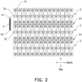
- FIG. 2 shows a top view of a battery monitoring unit 4 and battery sets 3 according to a first embodiment of the disclosure.
- the battery unit 31 located at one end of the battery set 3 has an expansion portion 32.
- the expansion portion 32 is formed in a center region of an end surface of the battery set 3 in the column direction.
- the battery unit 31 when the battery unit 31 is operating, the battery unit 31 expands, which causes the shell of the battery unit 31 to protrude outward deform.
- the deformation of the battery unit 31 squeezes devices around the battery set 3, such as the battery monitoring unit 4. Since the center region of one side surface of the battery unit 31 is farther from an edge of the battery unit 31, the expansion deformation of the center region is larger.
- the battery unit 31 is exemplified as having the cuboid shape.
- the center region of one side surface formed by the length and the height of the cuboid-shaped battery unit 31 that is, the "larger surface" of the cuboid
- the expansion portion 32 In other words, the center region of the side surface of the battery unit 31 is the intersecting region of two diagonals.
- the battery units 31 of each battery set 3 all have the expansion portions 32. Since the battery units 31 are disposed side by side, the deformations of the respective expansion portions 32 of the battery units 31 are added up, and the final added-up deformation is reflected in the expansion portions 32 of the battery units 31 located at one end of the battery sets 3 in the column direction.
- the battery monitoring unit 4 of the embodiment of the disclosure is disposed on the end surface of the battery set 3, and in the column direction, the battery monitoring unit 4 is staggered from the expansion portions 32.
- the battery monitoring unit 4 is disposed on the end surface of the battery set 3, and in the column direction, the battery monitoring unit 4 is staggered from the expansion portions 32. In this way, when the expansion portion 32 of each battery unit 31 is deformed, since the battery monitoring unit 4 is staggered from the expansion portion 32, the expansion portion 32 of each battery unit 31 will not squeeze the battery monitoring unit 4 to avoid affecting the normal operation of the battery monitoring unit 4 and improve the reliability of monitoring the battery signal.
- the battery sets 3 are disposed side by side in the row direction, and in the row direction, a junction 33 is formed between each two adjacent battery sets 3.
- the battery monitoring unit 4 is centrally disposed at the junction 33 of the two adjacent battery sets 3.
- the battery monitoring unit 4 is disposed across the two adjacent battery sets 3 in the row direction, and the battery monitoring unit 4 is equally divided by the junction 33.
- the junction 33 formed between the two adjacent battery sets 3 may be a gap or may be seamless.
- the junction 33 is the gap, the two adjacent battery sets 3 are disposed at an interval, and the gap may be used to accommodate a cushion pad.
- the junction 33 is seamless, the two adjacent battery sets 3 are directly attached to each other.
- the battery monitoring unit 4 is divided into a first part 41 and a second part 42.
- the shapes/sizes of the first part 41 and the second part 42 are basically the same.
- the first part 41 corresponds to one of the adjacent battery sets 3, and the first part 41 is staggered from the expansion portion 32 of the one of the battery sets 3.
- the second part 42 corresponds to the other one of the adjacent battery sets 3, and the second part 42 is staggered from the expansion portion 32 of the other one of the battery sets 3.
- the battery monitoring unit 4 when the size of the battery monitoring unit 4 is larger, since the battery monitoring unit 4 is centrally disposed at the junction 33 between the adjacent two battery sets 3, the battery monitoring unit 4 is as far away from the expansion portion 32 of each battery set 3 as possible, and corresponds to a position where the expansion deformation of the battery set 3 is smaller, so as to avoid squeezing the battery monitoring unit 4 due to the deformation of the expansion portion 32.
- FIG. 3 shows a top view of a battery monitoring unit 4 and battery sets 3 according to a second embodiment of the disclosure.
- the similarities between the second embodiment and the first embodiment will not be repeated here, and the difference lies in that an orthographic projection of the battery monitoring unit 4 on the battery sets 3 in the column direction at least partially coincides with the junction 33.
- the battery monitoring unit 4 of the embodiment is not centrally disposed at the junction 33, but in the row direction, the battery monitoring unit 4 is divided into the first part 41 and the second part 42 with unequal sizes by the junction 33.
- the size of the first part 41 is larger than the size of the second part 42.
- the size of the first part 41 may also be smaller than the size of the second part 42.
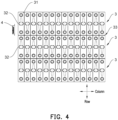
- FIG. 4 shows a top view of a battery monitoring unit 4 and battery sets 3 according to a third embodiment of the disclosure.
- the similarities between the third embodiment and the first embodiment will not be repeated, and the difference lies in that in the column direction, the battery monitoring unit 4 is disposed corresponding to only one battery set 3.
- the orthographic projection of the battery monitoring unit 4 on the battery set 3 falls in the end surface of only one battery set 3, and the orthographic projection is staggered from the expansion portion 32 of the battery set 3.
- the battery monitoring unit 4 may be disposed by adopting the embodiment shown in FIG. 4 .
- FIG. 5 shows a side view of a battery monitoring unit 4 and a battery set 3 according to the disclosure.
- the battery monitoring unit 4 and the end surface of the battery set 3 are disposed at an interval. Since the expansion portion 32 is formed on the end surface of the battery set 3, in the embodiment, the battery monitoring unit 4 and the end surface of the battery set 3 are disposed at an interval, such that when the expansion portion 32 is expanded and deformed, the interval between the battery monitoring unit 4 and the end surface of the battery set 3 can relieve the expansion of the expansion portion 32 to avoid the expansion portion 32 squeezing the battery monitoring unit 4 due to direct attachment between the battery monitoring unit 4 and the battery set 3.
- FIG. 6 shows a schematic view of an installation bracket 5 according to the disclosure.
- the battery pack 100 of the embodiment of the disclosure further includes the installation bracket 5.
- the installation bracket 5 is disposed in the sealed chamber of the case body 1 and is connected to the case body 1.
- the battery monitoring unit 4 is connected to the installation bracket 5.
- the installation bracket 5 is disposed on the end surface of the battery set 3 and has an installation surface 51 away from the battery set 3.
- the battery monitoring unit 4 is installed on the installation surface 51.
- the installation bracket 5 may be made of a metal material. Further, the installation bracket 5 may be made of a metal material with relatively high structural hardness, such as steel. Since the installation bracket 5 is connected to the case body 1, and since the structural hardness of the installation bracket 5 is relatively high, the installation bracket 5 is not easily deformed. When the battery set 3 expands and the expansion portion 32 squeezes the installation bracket 5, the installation bracket 5 can relieve the squeeze of the expansion portion 32, so that the battery monitoring unit 4 is not easily squeezed.
- the installation bracket 5 further has a protruding portion 52.
- the protruding portion 52 protrudes from the installation surface 51, so that the battery monitoring unit 4 and the installation surface 51 are disposed at an interval.
- the configuration of the protruding portion 52 enables the battery monitoring unit 4 and the installation surface 51 to be disposed at an interval.
- the interval between the battery monitoring unit 4 and the installation surface 51 can further relieve the squeeze of the expansion portion 32.
- the protruding portion 52 may also improve the structural strength of the installation bracket 5, so that the installation bracket 5 is less likely to be deformed when being squeezed by the expansion portion 32.
- the shape of the protruding portion 52 may be a protruding point, a protruding rib, other suitable shapes, or a combination of the above.
- the installation surface 51 is protruded with multiple protruding points, and the protruding points may be disposed in an array.
- the protruding portion 52 is the protruding rib, the number of protruding ribs may be multiple.
- Each protruding rib may extend in the row direction or in a direction perpendicular to the row direction.
- the protruding portion 52 may also be a combination of the protruding point and the protruding rib.
- the installation bracket 5 includes a main body portion 53, a first connecting portion 54, and a second connecting portion 55.
- One side surface of the main body portion 53 forms the installation surface 51, and the protruding portion 52 protrudes from the side surface of the main body portion 53.
- the battery monitoring unit 4 is installed on the main body portion 53.
- the first connecting portion 54 is connected to the main body portion 53 and is used to connect to a partition wall 13 of the case body 1.
- the second connecting portion 55 is connected to the main body portion 53 and is used to connect to a bottom wall of the lower case 12.
- first connecting portion 54, the second connecting portion 55, and the main body portion 53 are an integral structure.
- the first connecting portion 54 and the second connecting portion 55 may both be bent structures.
- the bent structures are formed on an edge of the main body portion 53 through integral bending.
- the first connecting portion 54 has a first via 541 and the second connecting portion 55 has a second via 551.
- the first via 541 and the second via 551 may allow bolts to pass therethrough, so that the installation bracket 5 may be connected to the case body 1 by the bolts, but not limited thereto.
- FIG. 7 shows a schematic view of an installation bracket 5 installed on a lower case 12 according to the disclosure.
- the case of the embodiment of the disclosure further includes a partition wall 13.
- the partition wall 13 may be integrally formed on the lower case 12, and the partition wall 13 extends in the row direction and divides the sealed chamber into a first accommodating space 14 and a second accommodating space 15.
- the battery set 3 is accommodated in the first accommodating space 14, and the battery monitoring unit 4 is accommodated in the second accommodating space 15.
- the first connecting portion 54 of the installation bracket 5 is connected to the partition wall 13, and the second connecting portion 55 of the installation bracket 5 is connected to the bottom wall of the lower case 12.
- the main body portion 53 of the installation bracket 5 may be a plate structure.
- the main body portion 53 is attached to a side surface of the partition wall 13 facing the second accommodating space 15.
- a side surface of the main body portion 53 facing away from the partition wall 13 is formed with the installation surface 51, so that the battery monitoring unit 4 is connected to one side of the installation bracket 5 facing away from the partition wall 13.
- the second connecting portion 55 of the installation bracket 5 is connected to the lower case 12.
- the installation bracket 5 can also play the role of conducting heat, so that heat generated by the battery monitoring unit 4 is conducted to the lower case 12 through the installation bracket 5.
- the partition wall 13 has a notch 131.
- the notch 131 is communicated with the first accommodating space 14 and the second accommodating space 15. Through the configuration of the notch 131, the coolant flows back and forth in the first accommodating space 14 and the second accommodating space 15, so that the coolant cools the battery sets 3 and the battery monitoring unit 4.
Landscapes
- Chemical & Material Sciences (AREA)
- Chemical Kinetics & Catalysis (AREA)
- Electrochemistry (AREA)
- General Chemical & Material Sciences (AREA)
- Engineering & Computer Science (AREA)
- Manufacturing & Machinery (AREA)
- Microelectronics & Electronic Packaging (AREA)
- Battery Mounting, Suspending (AREA)
Abstract
A battery pack (100) includes a battery set (3) and a battery monitoring unit (4), is provided. The battery set (3) includes multiple battery units (31). The battery units (31) are disposed side by side in a column direction. In the column direction, the battery unit (31) located at one end of the battery set (3) has an expansion portion (32). The expansion portion (32) is formed in a center region of an end surface of the battery set (3) in the column direction. The battery monitoring unit (4) is disposed on the end surface of the battery set (3). In the column direction, the battery monitoring unit (4) is staggered from the expansion portion (32).
Description
- The disclosure relates to the technical field of battery, and in particular to a battery pack.
- The battery monitoring unit (abbreviated as CSC) is a control system in a battery pack and is used to monitor battery information such as voltage and temperature of each battery unit or battery set. However, the battery monitoring unit in the related art is easily affected by other components in the battery pack, which results in reduced operational reliability.
- The disclosure provides a battery pack.
- The battery pack of an embodiment of the disclosure includes a battery set and a battery monitoring unit. The battery set includes a plurality of battery units, and the battery units are disposed side by side in a column direction. In the column direction, one of the battery units located at one end of the battery set has an expansion portion. The expansion portion is formed in a center region of an end surface of the battery set in the column direction. The battery monitoring unit is disposed on the end surface of the battery set, and in the column direction, the battery monitoring unit is staggered from the expansion portion.
- For a better understanding of the disclosure, reference may be made to exemplary embodiments shown in the following drawings. The components in the drawings are not necessarily to scale and related elements may be omitted, or in some instances proportions may have been exaggerated, so as to emphasize and clearly illustrate the features described herein. In addition, related elements or components can be variously arranged, as known in the art. Further, in the drawings, like reference numerals designate same or like parts throughout the several views.
-
FIG. 1 shows a schematic exploded view of a battery pack according to an embodiment of the disclosure. -
FIG. 2 shows a top view of a battery monitoring unit and battery sets according to a first embodiment of the disclosure. -
FIG. 3 shows a top view of a battery monitoring unit and battery sets according to a second embodiment of the disclosure. -
FIG. 4 shows a top view of a battery monitoring unit and battery sets according to a third embodiment of the disclosure. -
FIG. 5 shows a side view of a battery monitoring unit and a battery set according to the disclosure. -
FIG. 6 shows a schematic view of an installation bracket according to the disclosure. -
FIG. 7 shows a schematic view of an installation bracket installed on a lower case according to the disclosure. - The technical solutions in the exemplary embodiments of the disclosure will be described clearly and explicitly in conjunction with the drawings in the exemplary embodiments of the disclosure. The description proposed herein is just the exemplary embodiments for the purpose of illustrations only, not intended to limit the scope of the disclosure, so it should be understood that and various modifications and variations could be made thereto without departing from the scope of the disclosure.
- In the description of the present disclosure, unless otherwise specifically defined and limited, the terms "first", "second" and the like are only used for illustrative purposes and are not to be construed as expressing or implying a relative importance. The term "plurality" is two or more. The term "and/or" includes any and all combinations of one or more of the associated listed items.
- In particular, a reference to "the" object or "a" and "an" object is intended to denote also one of a possible plurality of such objects. Unless otherwise defined or described, the terms "connect", "fix" should be broadly interpreted, for example, the term "connect" can be "fixedly connect", "detachably connect", "integrally connect", "electrically connect" or "signal connect". The term "connect" also can be "directly connect" or "indirectly connect via a medium". For the persons skilled in the art, the specific meanings of the abovementioned terms in the present disclosure can be understood according to the specific situation.
- Further, in the description of the present disclosure, it should be understood that spatially relative terms, such as "above", "below" "inside", "outside" and the like, are described based on orientations illustrated in the figures, but are not intended to limit the exemplary embodiments of the present disclosure.
- In the context, it should also be understood that when an element or features is provided "outside" or "inside" of another element(s), it can be directly provided "outside" or "inside" of the other element, or be indirectly provided "outside" or "inside" of the another element(s) by an intermediate element.
- As shown in
FIG. 1, FIG. 1 shows a schematic exploded view of abattery pack 100 according to an embodiment of the disclosure. Thebattery pack 100 of the embodiment of the disclosure includes a case body 1, aconductor bar assembly 2,battery sets 3, and abattery monitoring unit 4. The case body 1 has a sealed chamber. Theconductor bar assembly 2, thebattery sets 3, and thebattery monitoring unit 4 are disposed in the sealed chamber. Theconductor bar assembly 2 may be disposed above thebattery sets 3 and may be used to connect poles of thebattery sets 3. Thebattery monitoring unit 4 is connected to theconductor bar assembly 2 and may be used to monitor a battery signal of thebattery sets 3. - It can be understood that the battery signal may include temperature, current, voltage, etc. of a battery.
- The terms "including" and "having" and any variations thereof in the embodiments of the disclosure are intended to cover non-exclusive inclusion. For example, a process, a method, a system, a product, or an equipment including a series of steps or units is not limited to the listed steps or units, but optionally also includes unlisted steps or units or optionally also includes other steps or components inherent to the process, the method, the product, or the equipment.
- A coolant is also accommodated in the sealed chamber. The coolant immerses the
conductor bar assembly 2, thebattery sets 3, and thebattery monitoring unit 4. Through the circulating flow of the coolant, heat generated by theconductor bar assembly 2, thebattery sets 3, and thebattery monitoring unit 4 is exported to dissipate the heat from theconductor bar assembly 2, thebattery sets 3, and thebattery monitoring unit 4. - The case body 1 includes an
upper case 11 and alower case 12. Theupper case 11 and thelower case 12 are sealed to form the sealed chamber for accommodating theconductive bar assembly 2, thebattery sets 3, and thebattery monitoring unit 4. - Each of the
battery sets 3 includes a plurality ofbattery units 31. Thebattery units 31 are disposed side by side in a column direction. As an example, eachbattery unit 31 has a cuboid shape, and a width direction of eachbattery unit 31 is parallel to the column direction. In other words, when thebattery unit 31 has the cuboid shape, twoadjacent battery units 31 are disposed side by side such that surfaces with the largest area are attached to each other. - Of course, the side-by-side arrangement of the
battery units 31 may also be that theadjacent battery units 31 are disposed side by side such that surfaces formed by widths and heights are attached to each other. - In addition, in the disclosure, the number of
battery sets 3 is not particularly limited. For example, the number ofbattery sets 3 may be one set, two sets, three sets, or other numbers. When the number ofbattery sets 3 is multiple, the plurality ofbattery sets 3 are disposed side by side in a row direction, wherein the row direction is perpendicular to the column direction. In this way, thebattery units 31 form a battery array. - In the embodiment, the
battery pack 100 includes threebattery sets 3. The threebattery sets 3 are disposed side by side in the row direction. Eachbattery set 3 includesmultiple battery units 31. Thebattery units 31 are disposed side by side in the column direction. - As shown in
FIG. 2, FIG. 2 shows a top view of abattery monitoring unit 4 andbattery sets 3 according to a first embodiment of the disclosure. Thebattery unit 31 located at one end of thebattery set 3 has anexpansion portion 32. Theexpansion portion 32 is formed in a center region of an end surface of the battery set 3 in the column direction. - Specifically, when the
battery unit 31 is operating, thebattery unit 31 expands, which causes the shell of thebattery unit 31 to protrude outward deform. The deformation of thebattery unit 31 squeezes devices around the battery set 3, such as thebattery monitoring unit 4. Since the center region of one side surface of thebattery unit 31 is farther from an edge of thebattery unit 31, the expansion deformation of the center region is larger. For ease of understanding, thebattery unit 31 is exemplified as having the cuboid shape. The center region of one side surface formed by the length and the height of the cuboid-shaped battery unit 31 (that is, the "larger surface" of the cuboid) is theexpansion portion 32. In other words, the center region of the side surface of thebattery unit 31 is the intersecting region of two diagonals. - Please continue to refer to
FIG. 2 . It can be understood that thebattery units 31 of each battery set 3 all have theexpansion portions 32. Since thebattery units 31 are disposed side by side, the deformations of therespective expansion portions 32 of thebattery units 31 are added up, and the final added-up deformation is reflected in theexpansion portions 32 of thebattery units 31 located at one end of the battery sets 3 in the column direction. - The
battery monitoring unit 4 of the embodiment of the disclosure is disposed on the end surface of the battery set 3, and in the column direction, thebattery monitoring unit 4 is staggered from theexpansion portions 32. - In the
battery pack 100 of the embodiment of the disclosure, thebattery monitoring unit 4 is disposed on the end surface of the battery set 3, and in the column direction, thebattery monitoring unit 4 is staggered from theexpansion portions 32. In this way, when theexpansion portion 32 of eachbattery unit 31 is deformed, since thebattery monitoring unit 4 is staggered from theexpansion portion 32, theexpansion portion 32 of eachbattery unit 31 will not squeeze thebattery monitoring unit 4 to avoid affecting the normal operation of thebattery monitoring unit 4 and improve the reliability of monitoring the battery signal. - Please continue to refer to
FIG. 2 . The battery sets 3 are disposed side by side in the row direction, and in the row direction, ajunction 33 is formed between each two adjacent battery sets 3. In the column direction, thebattery monitoring unit 4 is centrally disposed at thejunction 33 of the two adjacent battery sets 3. In other words, thebattery monitoring unit 4 is disposed across the two adjacent battery sets 3 in the row direction, and thebattery monitoring unit 4 is equally divided by thejunction 33. - It can be understood that in the row direction, the
junction 33 formed between the two adjacent battery sets 3 may be a gap or may be seamless. When thejunction 33 is the gap, the two adjacent battery sets 3 are disposed at an interval, and the gap may be used to accommodate a cushion pad. When thejunction 33 is seamless, the two adjacent battery sets 3 are directly attached to each other. - In the row direction, with the
junction 33 as a center line, thebattery monitoring unit 4 is divided into afirst part 41 and asecond part 42. The shapes/sizes of thefirst part 41 and thesecond part 42 are basically the same. In the column direction, thefirst part 41 corresponds to one of the adjacent battery sets 3, and thefirst part 41 is staggered from theexpansion portion 32 of the one of the battery sets 3. In the column direction, thesecond part 42 corresponds to the other one of the adjacent battery sets 3, and thesecond part 42 is staggered from theexpansion portion 32 of the other one of the battery sets 3. In this way, when the size of thebattery monitoring unit 4 is larger, since thebattery monitoring unit 4 is centrally disposed at thejunction 33 between the adjacent twobattery sets 3, thebattery monitoring unit 4 is as far away from theexpansion portion 32 of each battery set 3 as possible, and corresponds to a position where the expansion deformation of the battery set 3 is smaller, so as to avoid squeezing thebattery monitoring unit 4 due to the deformation of theexpansion portion 32. - As shown in
FIG. 3, FIG. 3 shows a top view of abattery monitoring unit 4 andbattery sets 3 according to a second embodiment of the disclosure. The similarities between the second embodiment and the first embodiment will not be repeated here, and the difference lies in that an orthographic projection of thebattery monitoring unit 4 on the battery sets 3 in the column direction at least partially coincides with thejunction 33. - Specifically, the
battery monitoring unit 4 of the embodiment is not centrally disposed at thejunction 33, but in the row direction, thebattery monitoring unit 4 is divided into thefirst part 41 and thesecond part 42 with unequal sizes by thejunction 33. - In the embodiment, the size of the
first part 41 is larger than the size of thesecond part 42. Of course, in some embodiments, the size of thefirst part 41 may also be smaller than the size of thesecond part 42. - As shown in
FIG. 4, FIG. 4 shows a top view of abattery monitoring unit 4 andbattery sets 3 according to a third embodiment of the disclosure. The similarities between the third embodiment and the first embodiment will not be repeated, and the difference lies in that in the column direction, thebattery monitoring unit 4 is disposed corresponding to only onebattery set 3. - In other words, in the column direction, the orthographic projection of the
battery monitoring unit 4 on the battery set 3 falls in the end surface of only onebattery set 3, and the orthographic projection is staggered from theexpansion portion 32 of thebattery set 3. - It can be understood that when the
battery pack 100 includes only onebattery set 3, thebattery monitoring unit 4 may be disposed by adopting the embodiment shown inFIG. 4 . - As shown in
FIG. 5, FIG. 5 shows a side view of abattery monitoring unit 4 and a battery set 3 according to the disclosure. Thebattery monitoring unit 4 and the end surface of the battery set 3 are disposed at an interval. Since theexpansion portion 32 is formed on the end surface of the battery set 3, in the embodiment, thebattery monitoring unit 4 and the end surface of the battery set 3 are disposed at an interval, such that when theexpansion portion 32 is expanded and deformed, the interval between thebattery monitoring unit 4 and the end surface of the battery set 3 can relieve the expansion of theexpansion portion 32 to avoid theexpansion portion 32 squeezing thebattery monitoring unit 4 due to direct attachment between thebattery monitoring unit 4 and thebattery set 3. - As shown in
FIG. 1 andFIG. 6, FIG. 6 shows a schematic view of aninstallation bracket 5 according to the disclosure. Thebattery pack 100 of the embodiment of the disclosure further includes theinstallation bracket 5. Theinstallation bracket 5 is disposed in the sealed chamber of the case body 1 and is connected to the case body 1. Thebattery monitoring unit 4 is connected to theinstallation bracket 5. - The
installation bracket 5 is disposed on the end surface of the battery set 3 and has aninstallation surface 51 away from thebattery set 3. Thebattery monitoring unit 4 is installed on theinstallation surface 51. Theinstallation bracket 5 may be made of a metal material. Further, theinstallation bracket 5 may be made of a metal material with relatively high structural hardness, such as steel. Since theinstallation bracket 5 is connected to the case body 1, and since the structural hardness of theinstallation bracket 5 is relatively high, theinstallation bracket 5 is not easily deformed. When the battery set 3 expands and theexpansion portion 32 squeezes theinstallation bracket 5, theinstallation bracket 5 can relieve the squeeze of theexpansion portion 32, so that thebattery monitoring unit 4 is not easily squeezed. - The
installation bracket 5 further has a protrudingportion 52. The protrudingportion 52 protrudes from theinstallation surface 51, so that thebattery monitoring unit 4 and theinstallation surface 51 are disposed at an interval. The configuration of the protrudingportion 52 enables thebattery monitoring unit 4 and theinstallation surface 51 to be disposed at an interval. The interval between thebattery monitoring unit 4 and theinstallation surface 51 can further relieve the squeeze of theexpansion portion 32. In addition, the protrudingportion 52 may also improve the structural strength of theinstallation bracket 5, so that theinstallation bracket 5 is less likely to be deformed when being squeezed by theexpansion portion 32. - It can be understood that the shape of the protruding
portion 52 may be a protruding point, a protruding rib, other suitable shapes, or a combination of the above. When the protrudingportion 52 is the protruding point, theinstallation surface 51 is protruded with multiple protruding points, and the protruding points may be disposed in an array. When the protrudingportion 52 is the protruding rib, the number of protruding ribs may be multiple. Each protruding rib may extend in the row direction or in a direction perpendicular to the row direction. Of course, the protrudingportion 52 may also be a combination of the protruding point and the protruding rib. - Please continue to refer to
FIG. 6 . Theinstallation bracket 5 includes amain body portion 53, a first connectingportion 54, and a second connectingportion 55. One side surface of themain body portion 53 forms theinstallation surface 51, and the protrudingportion 52 protrudes from the side surface of themain body portion 53. Thebattery monitoring unit 4 is installed on themain body portion 53. The first connectingportion 54 is connected to themain body portion 53 and is used to connect to apartition wall 13 of the case body 1. The second connectingportion 55 is connected to themain body portion 53 and is used to connect to a bottom wall of thelower case 12. - As an example, the first connecting
portion 54, the second connectingportion 55, and themain body portion 53 are an integral structure. The first connectingportion 54 and the second connectingportion 55 may both be bent structures. The bent structures are formed on an edge of themain body portion 53 through integral bending. - The first connecting
portion 54 has a first via 541 and the second connectingportion 55 has a second via 551. The first via 541 and the second via 551 may allow bolts to pass therethrough, so that theinstallation bracket 5 may be connected to the case body 1 by the bolts, but not limited thereto. - As shown in
FIG. 7, FIG. 7 shows a schematic view of aninstallation bracket 5 installed on alower case 12 according to the disclosure. The case of the embodiment of the disclosure further includes apartition wall 13. Thepartition wall 13 may be integrally formed on thelower case 12, and thepartition wall 13 extends in the row direction and divides the sealed chamber into a firstaccommodating space 14 and a secondaccommodating space 15. The battery set 3 is accommodated in the firstaccommodating space 14, and thebattery monitoring unit 4 is accommodated in the secondaccommodating space 15. The first connectingportion 54 of theinstallation bracket 5 is connected to thepartition wall 13, and the second connectingportion 55 of theinstallation bracket 5 is connected to the bottom wall of thelower case 12. - Referring to
FIG. 6 andFIG. 7 , themain body portion 53 of theinstallation bracket 5 may be a plate structure. Themain body portion 53 is attached to a side surface of thepartition wall 13 facing the secondaccommodating space 15. A side surface of themain body portion 53 facing away from thepartition wall 13 is formed with theinstallation surface 51, so that thebattery monitoring unit 4 is connected to one side of theinstallation bracket 5 facing away from thepartition wall 13. - Since the
battery monitoring unit 4 is installed on theinstallation bracket 5, the second connectingportion 55 of theinstallation bracket 5 is connected to thelower case 12. In this way, theinstallation bracket 5 can also play the role of conducting heat, so that heat generated by thebattery monitoring unit 4 is conducted to thelower case 12 through theinstallation bracket 5. - The
partition wall 13 has anotch 131. Thenotch 131 is communicated with the firstaccommodating space 14 and the secondaccommodating space 15. Through the configuration of thenotch 131, the coolant flows back and forth in the firstaccommodating space 14 and the secondaccommodating space 15, so that the coolant cools the battery sets 3 and thebattery monitoring unit 4. - Other embodiments of the disclosure will be apparent to those skilled in the art from consideration of the specification and practice of the disclosure disclosed herein. The disclosure is intended to cover any variations, uses or adaptations of the disclosure. These variations, uses, or adaptations follow the general principles of the disclosure and include common general knowledge or conventional technical means in the art that are not disclosed in the present disclosure. The specification and embodiments are illustrative.
Claims (13)
- A battery pack (100), comprising:a battery set (3), including a plurality of battery units (31), wherein the battery units (31) are disposed side by side in a column direction; in the column direction, one of the battery units (31) located at one end of the battery set (3) has an expansion portion (32), and the expansion portion (32) is formed in a center region of an end surface of the battery set (3) in the column direction; anda battery monitoring unit (4), disposed on the end surface of the battery set (3), wherein in the column direction, the battery monitoring unit (4) is staggered from the expansion portion (32).
- The battery pack (100) according to claim 1, wherein the battery set (3) is plural in number, and the plurality of battery sets (3) are disposed side by side in a row direction, wherein the row direction is perpendicular to the column direction;
an orthographic projection of the battery monitoring unit (4) on the battery sets (3) in the column direction at least partially coincides with a junction (33) of adjacent two of the battery sets (3). - The battery pack (100) according to claim 2, wherein in the column direction, the battery monitoring unit (4) is centrally disposed at the junction (33) of the adjacent two of the battery sets (3).
- The battery pack (100) according to claim 1, wherein the battery monitoring unit (4) and the end surface of the battery set (3) are disposed at an interval.
- The battery pack (100) according to claim 1, further comprising:a case body (1), having a sealed chamber, wherein the battery set (3) and the battery monitoring unit (4) are disposed in the sealed chamber; andan installation bracket (5), disposed in the sealed chamber and connected to the case body (1), wherein the battery monitoring unit (4) is connected to the installation bracket (5).
- The battery pack (100) according to claim 2, further comprising:a case body (1), having a sealed chamber, wherein the battery sets (3) and the battery monitoring unit (4) are disposed in the sealed chamber; andan installation bracket (5), disposed in the sealed chamber and connected to the case body (1), wherein the battery monitoring unit (4) is connected to the installation bracket (5).
- The battery pack (100) according to claim 3, further comprising:a case body (1), having a sealed chamber, wherein the battery sets (3) and the battery monitoring unit (4) are disposed in the sealed chamber; andan installation bracket (5), disposed in the sealed chamber and connected to the case body (1), wherein the battery monitoring unit (4) is connected to the installation bracket (5).
- The battery pack (100) according to claim 4, further comprising:a case body (1), having a sealed chamber, wherein the battery set and the battery monitoring unit (4) are disposed in the sealed chamber; andan installation bracket (5), disposed in the sealed chamber and connected to the case body (1), wherein the battery monitoring unit (4) is connected to the installation bracket (5).
- The battery pack (100) according to claim 5, wherein the installation bracket (5) is disposed on the end surface of the battery set (3) and has an installation surface (51) away from the battery set (3), and the battery monitoring unit (4) is installed on the installation surface (51).
- The battery pack (100) according to claim 9, wherein the installation bracket (5) further has a protruding portion (52), and the protruding portion (52) protrudes from the installation surface (51) and enables the battery monitoring unit (4) and the installation surface (51) to be disposed at an interval.
- The battery pack (100) according to claim 5, wherein the case body (1) further comprises a partition wall (13), the partition wall (13) extends in a row direction and divides the sealed chamber into a first accommodating space (14) and a second accommodating space (15), the battery set (3) is accommodated in the first accommodating space (14), and the battery monitoring unit (4) is accommodated in the second accommodating space (15);
the installation bracket (5) is connected to the partition wall (13). - The battery pack (100) according to claim 11, wherein the battery monitoring unit (4) is connected to a side of the installation bracket (5) away from the partition wall (13).
- The battery pack (100) according to claim 11, wherein the installation bracket (5) comprises:a main body portion (53), wherein the battery monitoring unit (4) is installed on the main body portion (53);a first connecting portion (54), connected to the main body portion (53) and connected to the partition wall (13); anda second connecting portion (55), connected to the main body portion (53) and connected to a bottom wall of the case body (1).
Applications Claiming Priority (1)
| Application Number | Priority Date | Filing Date | Title |
|---|---|---|---|
| CN202210770619.5A CN115084682A (en) | 2022-06-30 | 2022-06-30 | Battery pack |
Publications (1)
| Publication Number | Publication Date |
|---|---|
| EP4300655A1 true EP4300655A1 (en) | 2024-01-03 |
Family
ID=83151784
Family Applications (1)
| Application Number | Title | Priority Date | Filing Date |
|---|---|---|---|
| EP22193048.0A Pending EP4300655A1 (en) | 2022-06-30 | 2022-08-31 | Battery pack |
Country Status (3)
| Country | Link |
|---|---|
| US (1) | US20240006704A1 (en) |
| EP (1) | EP4300655A1 (en) |
| CN (1) | CN115084682A (en) |
Citations (3)
| Publication number | Priority date | Publication date | Assignee | Title |
|---|---|---|---|---|
| EP3726609A1 (en) * | 2018-01-19 | 2020-10-21 | Contemporary Amperex Technology Co., Limited | Installation support frame for cell supervisory circuit, battery pack, and automobile |
| WO2021149299A1 (en) * | 2020-01-23 | 2021-07-29 | 三洋電機株式会社 | Power supply device, and electric vehicle and power storage device equipped with this power supply device |
| US20220085346A1 (en) * | 2020-09-15 | 2022-03-17 | Lithium Power Inc. | Battery Pack with a Plurality of Battery Cells |
-
2022
- 2022-06-30 CN CN202210770619.5A patent/CN115084682A/en active Pending
- 2022-08-31 EP EP22193048.0A patent/EP4300655A1/en active Pending
- 2022-09-01 US US17/901,807 patent/US20240006704A1/en active Pending
Patent Citations (3)
| Publication number | Priority date | Publication date | Assignee | Title |
|---|---|---|---|---|
| EP3726609A1 (en) * | 2018-01-19 | 2020-10-21 | Contemporary Amperex Technology Co., Limited | Installation support frame for cell supervisory circuit, battery pack, and automobile |
| WO2021149299A1 (en) * | 2020-01-23 | 2021-07-29 | 三洋電機株式会社 | Power supply device, and electric vehicle and power storage device equipped with this power supply device |
| US20220085346A1 (en) * | 2020-09-15 | 2022-03-17 | Lithium Power Inc. | Battery Pack with a Plurality of Battery Cells |
Also Published As
| Publication number | Publication date |
|---|---|
| US20240006704A1 (en) | 2024-01-04 |
| CN115084682A (en) | 2022-09-20 |
Similar Documents
| Publication | Publication Date | Title |
|---|---|---|
| US8329324B2 (en) | Voltage sensing member and battery module employed with the same | |
| CN111052494B (en) | Battery module and battery pack | |
| US7663867B2 (en) | Secondary circuit terminal block design for fixed type circuit breakers | |
| US20190006643A1 (en) | Battery module | |
| US11431061B2 (en) | Bus bar module and battery pack | |
| US11867467B2 (en) | Cooling device with superimposed fin groups | |
| JP6608653B2 (en) | Battery module | |
| JP6691083B2 (en) | Bus bar, bus bar module, and battery pack | |
| JP2015138605A (en) | Wiring module and power storage module | |
| JP5096842B2 (en) | Battery storage unit | |
| JP7259721B2 (en) | battery module | |
| CN112753123A (en) | Sodium secondary battery module | |
| EP4300655A1 (en) | Battery pack | |
| EP4250448A1 (en) | Energy storage rack | |
| JP2019096510A (en) | Battery module | |
| JP6740722B2 (en) | Battery pack and battery module | |
| JP2019197647A (en) | Battery back | |
| JP6653295B2 (en) | Busbar module electrode contact structure | |
| US20120301770A1 (en) | Electrochemical cell | |
| CN217691301U (en) | Battery pack | |
| WO2013128257A1 (en) | Fuel cell unit and fuel cell vehicle | |
| CN217691349U (en) | Battery pack | |
| EP3751632A1 (en) | Battery module and method for producing a battery module | |
| CN221176678U (en) | Side-mounted widened terminal strip | |
| JP2016100045A (en) | Power storage device |
Legal Events
| Date | Code | Title | Description |
|---|---|---|---|
| PUAI | Public reference made under article 153(3) epc to a published international application that has entered the european phase |
Free format text: ORIGINAL CODE: 0009012 |
|
| STAA | Information on the status of an ep patent application or granted ep patent |
Free format text: STATUS: REQUEST FOR EXAMINATION WAS MADE |
|
| 17P | Request for examination filed |
Effective date: 20220831 |
|
| AK | Designated contracting states |
Kind code of ref document: A1 Designated state(s): AL AT BE BG CH CY CZ DE DK EE ES FI FR GB GR HR HU IE IS IT LI LT LU LV MC MK MT NL NO PL PT RO RS SE SI SK SM TR |