EP4300652A2 - Lithium-ionen-batterie, batteriemodul, batteriepack und elektrische vorrichtung - Google Patents
Lithium-ionen-batterie, batteriemodul, batteriepack und elektrische vorrichtung Download PDFInfo
- Publication number
- EP4300652A2 EP4300652A2 EP23210059.4A EP23210059A EP4300652A2 EP 4300652 A2 EP4300652 A2 EP 4300652A2 EP 23210059 A EP23210059 A EP 23210059A EP 4300652 A2 EP4300652 A2 EP 4300652A2
- Authority
- EP
- European Patent Office
- Prior art keywords
- lithium
- ion battery
- current collector
- battery
- electrolytic solution
- Prior art date
- Legal status (The legal status is an assumption and is not a legal conclusion. Google has not performed a legal analysis and makes no representation as to the accuracy of the status listed.)
- Pending
Links
Images

Classifications
-
- H—ELECTRICITY
- H01—ELECTRIC ELEMENTS
- H01M—PROCESSES OR MEANS, e.g. BATTERIES, FOR THE DIRECT CONVERSION OF CHEMICAL ENERGY INTO ELECTRICAL ENERGY
- H01M4/00—Electrodes
- H01M4/02—Electrodes composed of, or comprising, active material
- H01M4/36—Selection of substances as active materials, active masses, active liquids
- H01M4/362—Composites
- H01M4/366—Composites as layered products
-
- H—ELECTRICITY
- H01—ELECTRIC ELEMENTS
- H01M—PROCESSES OR MEANS, e.g. BATTERIES, FOR THE DIRECT CONVERSION OF CHEMICAL ENERGY INTO ELECTRICAL ENERGY
- H01M10/00—Secondary cells; Manufacture thereof
- H01M10/05—Accumulators with non-aqueous electrolyte
- H01M10/056—Accumulators with non-aqueous electrolyte characterised by the materials used as electrolytes, e.g. mixed inorganic/organic electrolytes
- H01M10/0564—Accumulators with non-aqueous electrolyte characterised by the materials used as electrolytes, e.g. mixed inorganic/organic electrolytes the electrolyte being constituted of organic materials only
- H01M10/0566—Liquid materials
- H01M10/0568—Liquid materials characterised by the solutes
-
- H—ELECTRICITY
- H01—ELECTRIC ELEMENTS
- H01M—PROCESSES OR MEANS, e.g. BATTERIES, FOR THE DIRECT CONVERSION OF CHEMICAL ENERGY INTO ELECTRICAL ENERGY
- H01M10/00—Secondary cells; Manufacture thereof
- H01M10/05—Accumulators with non-aqueous electrolyte
- H01M10/052—Li-accumulators
- H01M10/0525—Rocking-chair batteries, i.e. batteries with lithium insertion or intercalation in both electrodes; Lithium-ion batteries
-
- H—ELECTRICITY
- H01—ELECTRIC ELEMENTS
- H01M—PROCESSES OR MEANS, e.g. BATTERIES, FOR THE DIRECT CONVERSION OF CHEMICAL ENERGY INTO ELECTRICAL ENERGY
- H01M10/00—Secondary cells; Manufacture thereof
- H01M10/05—Accumulators with non-aqueous electrolyte
- H01M10/056—Accumulators with non-aqueous electrolyte characterised by the materials used as electrolytes, e.g. mixed inorganic/organic electrolytes
- H01M10/0564—Accumulators with non-aqueous electrolyte characterised by the materials used as electrolytes, e.g. mixed inorganic/organic electrolytes the electrolyte being constituted of organic materials only
- H01M10/0566—Liquid materials
- H01M10/0567—Liquid materials characterised by the additives
-
- H—ELECTRICITY
- H01—ELECTRIC ELEMENTS
- H01M—PROCESSES OR MEANS, e.g. BATTERIES, FOR THE DIRECT CONVERSION OF CHEMICAL ENERGY INTO ELECTRICAL ENERGY
- H01M10/00—Secondary cells; Manufacture thereof
- H01M10/05—Accumulators with non-aqueous electrolyte
- H01M10/058—Construction or manufacture
- H01M10/0587—Construction or manufacture of accumulators having only wound construction elements, i.e. wound positive electrodes, wound negative electrodes and wound separators
-
- H—ELECTRICITY
- H01—ELECTRIC ELEMENTS
- H01M—PROCESSES OR MEANS, e.g. BATTERIES, FOR THE DIRECT CONVERSION OF CHEMICAL ENERGY INTO ELECTRICAL ENERGY
- H01M4/00—Electrodes
- H01M4/02—Electrodes composed of, or comprising, active material
- H01M4/62—Selection of inactive substances as ingredients for active masses, e.g. binders, fillers
- H01M4/624—Electric conductive fillers
- H01M4/626—Metals
-
- H—ELECTRICITY
- H01—ELECTRIC ELEMENTS
- H01M—PROCESSES OR MEANS, e.g. BATTERIES, FOR THE DIRECT CONVERSION OF CHEMICAL ENERGY INTO ELECTRICAL ENERGY
- H01M4/00—Electrodes
- H01M4/02—Electrodes composed of, or comprising, active material
- H01M4/64—Carriers or collectors
- H01M4/66—Selection of materials
- H01M4/665—Composites
- H01M4/667—Composites in the form of layers, e.g. coatings
-
- Y—GENERAL TAGGING OF NEW TECHNOLOGICAL DEVELOPMENTS; GENERAL TAGGING OF CROSS-SECTIONAL TECHNOLOGIES SPANNING OVER SEVERAL SECTIONS OF THE IPC; TECHNICAL SUBJECTS COVERED BY FORMER USPC CROSS-REFERENCE ART COLLECTIONS [XRACs] AND DIGESTS
- Y02—TECHNOLOGIES OR APPLICATIONS FOR MITIGATION OR ADAPTATION AGAINST CLIMATE CHANGE
- Y02E—REDUCTION OF GREENHOUSE GAS [GHG] EMISSIONS, RELATED TO ENERGY GENERATION, TRANSMISSION OR DISTRIBUTION
- Y02E60/00—Enabling technologies; Technologies with a potential or indirect contribution to GHG emissions mitigation
- Y02E60/10—Energy storage using batteries
-
- Y—GENERAL TAGGING OF NEW TECHNOLOGICAL DEVELOPMENTS; GENERAL TAGGING OF CROSS-SECTIONAL TECHNOLOGIES SPANNING OVER SEVERAL SECTIONS OF THE IPC; TECHNICAL SUBJECTS COVERED BY FORMER USPC CROSS-REFERENCE ART COLLECTIONS [XRACs] AND DIGESTS
- Y02—TECHNOLOGIES OR APPLICATIONS FOR MITIGATION OR ADAPTATION AGAINST CLIMATE CHANGE
- Y02P—CLIMATE CHANGE MITIGATION TECHNOLOGIES IN THE PRODUCTION OR PROCESSING OF GOODS
- Y02P70/00—Climate change mitigation technologies in the production process for final industrial or consumer products
- Y02P70/50—Manufacturing or production processes characterised by the final manufactured product
Definitions
- This application relates to energy storage lithium-ion batteries, and in particular, to a lithium-ion battery with a high energy density, a battery module, a battery pack, and an electrical device.
- Lithium-ion batteries have become the most popular energy storage systems by virtue of a high operating potential, longevity, and environmental friendliness, and have now been widely used in fields such as battery electric vehicles, hybrid electric vehicles, and smart grids.
- safety issues of the lithium-ion batteries have bottlenecked the application and popularization of the lithium-ion batteries to a great extent. Therefore, it is necessary to provide a high-safety lithium-ion battery design.
- a jell-roll lithium-ion battery is prone to lithium plating on a convex surface of a negative electrode.
- the lithium plating is the severest on the convex surface of an innermost circle of negative electrode.
- a length of a concave surface of a positive electrode is greater than a length of the corresponding convex surface of the negative electrode. Therefore, a negative electrode material can hardly accept all lithium migrated from the positive electrode during charging.
- Excess lithium is deposited in the form of lithium metal on the surface of the negative electrode, resulting in a phenomenon of lithium plating. Dendrites resulting from the lithium plating are much prone to pierce the separator to cause a problem of internal short circuits.
- a positive current collector is much prone to contact a negative current collector to cause internal short circuits in the battery.
- the short circuits lead to a surge of a temperature of a battery cell, and, when combined with the highly active lithium simple substance generated at a corner, are much prone to cause fire and explosion of the battery cell.
- This application is a result of research targeted at the foregoing technical problems, and aims to provide a lithium-ion battery, a battery module, a battery pack, and an electrical device, so as to solve the problem of internal short circuits caused by lithium plating at the corner on the convex surface of the innermost cycle of negative electrode of the jelly-roll lithium-ion battery, and improve safety of the lithium-ion battery.
- a lithium-ion battery including: an electrode assembly and an electrolytic solution.
- the electrode assembly includes a positive electrode plate and a negative electrode plate that are wound together, and a separator located between the positive electrode plate and the negative electrode plate, the negative electrode plate includes a negative current collector and a negative material layer disposed on at least one surface of the negative current collector, and the positive electrode plate includes a positive current collector and a positive material layer disposed on at least one surface of the positive current collector.
- the positive current collector includes a support layer and a metallic conductive layer, and the metallic conductive layer is disposed on at least one of two surfaces of the support layer.
- the electrolytic solution contains a first lithium salt Li x R 1 (SO 2 N) x SO 2 R 2 , where R 1 and R 2 each independently represent an alkyl with 1 to 20 fluorine atoms or carbon atoms, or a fluoroalkyl with 1 to 20 carbon atoms, or a fluoroalkoxyl with 1 to 20 carbon atoms, and x is an integer of 1, 2, or 3.
- the support layer has a thickness of ⁇ 2, which satisfies: 1 ⁇ m ⁇ ⁇ 2 ⁇ 30 ⁇ m
- the lithium-ion battery according to this application can solve the problem of internal short circuits caused by lithium plating at the corner on the convex surface of the innermost cycle of negative electrode of the jelly-roll lithium-ion battery, and improve safety of the lithium-ion battery.
- the support layer is of a given thickness, thereby further ensuring a relatively high resistance of the positive current collector, and reducing the temperature of the battery significantly when an internal short circuit occurs in the battery.
- a Young's modulus E of the support layer is greater than or equal to 1.9 GPa, optionally 4 GPa ⁇ E ⁇ 20 GPa.
- a volume resistivity of the support layer is not less than 1.0 ⁇ 10 -5 ⁇ m.
- the metallic conductive layer is disposed on both surfaces of the support layer.
- a bonding force F between the support layer (101) and the metallic conductive layer (102) in the current collector (63, 10) satisfies100 N/m ⁇ F ⁇ 390 N/m.
- a mass fraction of the first lithium salt is 5% to 30%, optionally 6% to 25%, and further optionally 11% to 20%.
- the electrolytic solution further contains a second lithium salt, and the second lithium salt is at least one selected from LiPF 6 , LiAsF 6 , or LiBF 4 .
- a mass percent of the second lithium salt is less than or equal to 10%, and optionally less than or equal to 3%.
- a viscosity of the electrolytic solution is less than or equal to 4 mPa ⁇ s, optionally less than or equal to 3.5 mPa ⁇ s.
- the battery module includes the lithium-ion battery according to this application.
- the battery pack includes at least one of the lithium-ion battery according to this application or the battery module according to this application.
- the electrical device includes at least one of the lithium-ion battery according to this application, the battery module according to this application, or the battery pack according to this application.
- this application provides a lithium-ion battery, including: an electrode assembly and an electrolytic solution.
- the electrode assembly includes a positive electrode plate and a negative electrode plate that are wound together, and a separator located between the positive electrode plate and the negative electrode plate, the negative electrode plate includes a negative current collector and a negative material layer disposed on at least one surface of the negative current collector, and the positive electrode plate includes a positive current collector and a positive material layer disposed on at least one surface of the positive current collector.
- the positive current collector includes a support layer and a metallic conductive layer, and the metallic conductive layer is disposed on at least one of two surfaces of the support layer.
- the electrolytic solution contains a first lithium salt Li x R 1 (SO 2 N) x SO 2 R 2 , where R 1 and R 2 each independently represent an alkyl with 1 to 20 fluorine atoms or carbon atoms, or a fluoroalkyl with 1 to 20 carbon atoms, or a fluoroalkoxyl with 1 to 20 carbon atoms, and x is an integer of 1, 2, or 3.
- La is an arc length of a convex surface of the negative current collector corresponding to a concave surface of an innermost first circle of positive electrode in a jelly-roll structure of the electrode assembly
- Lc is an arc length of a concave surface of an innermost first circle of positive current collector in the jelly-roll structure of the electrode assembly.
- La and Lc are measured in mm.
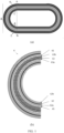
- FIG. 1 is a schematic diagram of an electrode assembly of a lithium-ion battery according to an embodiment of this application, where FIG. 1(a) is a schematic diagram of a method for measuring La and Lc, and FIG. 1(b) is a schematic diagram of an arc-shaped bend portion 6 (that is, a corner of a jelly-roll structure);
- the electrode assembly according to this application includes a positive electrode plate and a negative electrode plate that are wound together, and a separator (61) located between the positive electrode plate and the negative electrode plate.
- the negative electrode plate includes a negative current collector (62) and a negative material layer (62a) disposed on at least one surface (for example, an convex surface) of the negative current collector, or the negative material layers (62a, 62b) may be disposed on both surfaces (that is, an concave surface and the convex surface) of the negative current collector.
- the positive electrode plate includes a positive current collector (63) and a positive material layer (63a) disposed on at least one surface (for example, an concave surface) of the positive current collector, or the positive material layers (63a, 63b) may be disposed on both surfaces (that is, the concave surface and a convex surface) of the positive current collector.
- the positive electrode plate includes a positive current collector and a positive material layer disposed on at least one surface of the positive current collector.
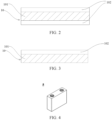
- FIG. 2 to FIG. 3 are schematic structural diagrams of a positive current collector according to some embodiments of this application.
- FIG. 2 is a schematic structural diagram of a positive current collector 10 according to an embodiment of this application.
- the positive current collector 10 includes a support layer 101 disposed in a stacked manner and two metallic conductive layers 102 located on two surfaces of the support layer 101 respectively.
- the support layer is configured to carry the metallic conductive layer, serves to support and protect the metallic conductive layer.
- the metallic conductive layer is configured to carry an electrode active material layer and provide electrons for the electrode active material layer, that is, serves to conduct electricity and collect current.
- FIG. 3 is a schematic structural diagram of a positive current collector 10 according to another embodiment of this application.
- the positive current collector 10 includes a support layer 101 disposed in a stacked manner and one metallic conductive layer 102 located on one surface of the support layer 101.
- the positive current collector 10 may further include other optional structural layers.
- a protection layer for example, metal oxide
- a protection layer may be additionally disposed on the conductive layer to protect the conductive layer against chemical corrosion, mechanical damage, and the like, and to ensure the operating stability and longevity of the positive current collector 10.
- the support layer serves a function of supporting and protecting the metallic conductive layer.
- the support layer is generally made of an organic polymer material or a polymer composite material. Therefore, the density of the support layer is usually lower than that of the conductive layer, thereby increasing a weight energy density of the battery significantly in contrast to a conventional metallic current collector.
- the metallic layer is relatively thin, thereby further increasing the weight energy density of the battery.
- the support layer well carry and protect the conductive layer located on a surface of the support layer, thereby reducing the probability of electrode plate fracture that often occurs in a conventional current collector.
- the thickness of the support layer is ⁇ 2.
- ⁇ 2 satisfies: 1 ⁇ m ⁇ ⁇ 2 ⁇ 30 ⁇ m, and further optionally 1 ⁇ m ⁇ ⁇ 2 ⁇ 20 ⁇ m; and still further optionally 1 ⁇ m ⁇ ⁇ 2 ⁇ 15 ⁇ m.
- the support layer is made of an organic polymer film of a given thickness, thereby further ensuring a relatively high resistance of the positive current collector, and reducing the temperature of the battery significantly when an internal short circuit occurs in the battery.
- the Young's modulus E of the support layer is optionally greater than or equal to 1.9 GPa. Further, 4 GPa ⁇ E ⁇ 20 GPa. In some embodiments, the Young's modulus E of the support layer is 1.9 GPa, 2.5 GPa, 4 GPa, 5 GPa, 6 GPa, 7 GPa, 8 GPa, 9 GPa, 10 GPa, 11 GPa, 12 GPa, 13 GPa, 14 GPa, 15 GPa, 16 GPa, 17 GPa, 18 GPa, 19 GPa, or 20 GPa.
- the range of the Young's modulus E of the support layer may be a value range that ends with any two thereof.
- the Young's modulus of the support layer falls within the foregoing range, thereby ensuring that the support layer is rigid enough to fulfill the supporting function of the support layer for the metallic conductive layer, and ensuring overall strength of the positive current collector.
- the support layer does not elongate or deform excessively, thereby preventing the support layer and the metallic conductive layer from breaking. This increases the bonding force between the support layer and the metallic conductive layer, reduces the probability of detaching, ensures relatively high mechanical stability and operating stability of the positive current collector, and in turn, and enables an electrochemical device to achieve relatively high electrochemical performance and a relatively long cycle life.
- a volume resistivity of the support layer is not less than 1.0 ⁇ 10 -5 ⁇ m. Due to a relatively high volume resistivity of the support layer, a short-circuit resistance of the electrochemical device can be increased when the electrochemical device incurs an internal short circuit in abnormal circumstances such as nail penetration, thereby improving the nail-penetration safety performance of the electrochemical device.
- the material of the support layer may be at least one selected from an insulating polymer material, an insulating polymer composite material, a conductive polymer material, or a conductive polymer composite material.
- the insulating polymer material is at least one selected from polyurethane, polyamide, polyterephthalate, polyimide, polyethylene, polypropylene, polystyrene, polyvinyl chloride, poly(acrylonitrile-co-butadiene-co-styrene), polybutanediol terephthalate, poly-p-phenylene terephthamide, polyphenylene ether, polyoxymethylene, epoxy resin, phenol-formaldehyde resin, polytetrafluoroethylene, polyvinylidene difluoride, silicone rubber, polycarbonate, or polyphenylene sulfide.
- the insulating polymer composite material is selected from a composite of an insulating polymer material and an inorganic material, where the inorganic material is preferably at least one of a ceramic material, a glass material, or a ceramic composite material.
- the foregoing conductive polymer material is selected from a polythiazyl-based polymer material or a doped conjugated polymer material, and optionally is at least one of polypyrrole, polyacetylene, polyaniline, or polythiophene.
- the conductive polymer composite material is selected from a composite of an insulating polymer material and a conductive material.
- the conductive material is at least one selected from a conductive carbon material, a metal material, or a composite conductive material.
- the conductive carbon material is at least one selected from carbon black, carbon nanotubes, graphite, acetylene black, or graphene.
- the metal material is at least one selected from nickel, iron, copper, aluminum, or an alloy thereof.
- the composite conductive material is at least one selected from nickel-coated graphite powder or nickel-coated carbon fiber.
- the material of the support layer according to this application is preferably an insulating polymer material or an insulating polymer composite material.
- the metallic conductive layer serves to conduct electricity and collect current, and is configured to provide electrons for the electrode active material layer.
- the conductive layer is much thinner than that in the conventional metallic current collector, and the density of the support layer is lower than that of metal, thereby reducing the weight of the lithium-ion battery on the basis of ensuring high conductive performance and high current-collecting performance of the conductive layer, and in turn, increasing the energy density of the lithium-ion battery.
- the metallic conductive layer in the positive current collector may be located on just a single surface of the support layer, or may be located on both upper and lower surfaces of the support layer. Preferably, the metallic conductive layer is located on both upper and lower surfaces of the support layer. In this application, when the metallic conductive layer is located on both upper and lower surfaces of the support layer, both surfaces of the positive current collector are highly electronically conductive. Therefore, active material layers may be disposed on both upper and lower surfaces of the positive current collector, thereby effectively increasing the utilization rate of the positive current collector in the battery cell, and in turn, increasing the volumetric energy density and mass energy density of the battery cell.
- the metallic conductive layer of the positive current collector is made of conductive metal.
- the conductive metal may be one or more of aluminum, aluminum alloy, nickel, or nickel alloy, and preferably aluminum or aluminum alloy.
- the weight percent of the aluminum element in the aluminum alloy is preferably at least 90%.
- the aluminum alloy may be, for example, aluminum-zirconium alloy.
- the thickness of the metallic conductive layer is denoted by ⁇ 1 ( ⁇ m).
- the thickness ⁇ 1 of the metallic conductive layer in the positive current collector is expressed in ⁇ m, and is 0.52 to 2.4, preferably 0.55 to 2.0, and more preferably 0.8 to 1.3.
- the thickness of the metallic conductive layer of the positive current collector is controlled to fall within such a range that the resistance of the positive current collector is moderate, thereby achieving both a long cycle life and a high mass energy density.
- the thickness of the metallic conductive layer of the positive current collector is excessive, the mass energy density of the battery will be reduced.
- the thickness of the metal conductive layer of the positive current collector is deficient, although the mass energy density of the battery can be significantly improved, the resistance of the current collector will be excessive. Another consequence is that the conductive layer of the positive current collector is unable to withstand corrosion by the lithium salt configured to suppress corner lithium plating in the electrolytic solution, thereby deteriorating the cycle life of the battery.
- a bonding force between the support layer and the metallic conductive layer in the current collector is expressed as F, where 100 N/m ⁇ F ⁇ 390 N/m.
- the bonding force helps to form a firmer and more stable bond between the support layer and the metallic conductive layer, helps to improve structural stability of the current collector in a corner region of a jelly-roll battery, keeps the metallic conductive layer from peeling off, achieves a stable current-conducting capability, and helps to alleviate the problem of corner lithium plating of the battery.
- the bonding force F between the support layer and the metallic conductive layer in the current collector is determined by the following method: selecting a specimen of a current collector in which the conductive layer is disposed on a single side of the support layer, affixing 3M double-sided tape onto a stainless steel sheet evenly under a room temperature and a normal pressure, and then affixing the specimen onto the double-sided tape evenly, where the width of the specimen is 2 cm.
- the bonding force between the support layer and the 3M double-sided tape is greater than the bonding force between the support layer and the metallic conductive layer, using a GoTech tensile testing machine to peel off the conductive layer of the specimen from the insulating layer, reading a maximum tensile force on a tension and shift data chart, and dividing the readout by 0.02 (unit: N) to obtain the bonding force F (N/m) between the support layer and the metallic conductive layer in the current collector.
- the positive active material is selected from materials capable of deintercalating and intercalating lithium ions.
- the positive active material may be one or more selected from lithium iron phosphate, lithium manganese iron phosphate, lithium cobalt oxide, lithium nickel oxide, lithium manganese oxide, lithium nickel manganese oxide, lithium nickel cobalt manganese oxide, or lithium nickel cobalt aluminum oxide, or a compound formed by adding other transition metals or non-transition metals into any of the foregoing compounds.
- this application is not limited to such materials, and conventional positive active materials in the field of lithium batteries may be employed instead.
- the positive material layer may further include a conductive agent and a binder.
- the type and content of the conductive agent and the binder are not specifically limited. Conventional types and content of the conductive agent and the binder, which are commonly used in the positive material layer of lithium batteries, may be selected according to actual needs.
- the negative electrode plate includes a negative current collector and a negative material layer disposed on at least one surface of the negative current collector.
- the negative material layer may be disposed on just one of two surfaces of the negative current collector or on both surfaces of the negative current collector.
- the negative current collector is made of copper or copper alloy.
- the negative material layer is made of a negative active material.
- the type of the negative active material is not specifically limited, and is preferably one or more selected from graphite, soft carbon, hard carbon, mesocarbon microbeads, carbon fibers, carbon nanotubes, simple-substance silicon, silicon-oxygen compound, silicon-carbon compound, silicon-carbon composite, or lithium titanium oxide.
- the negative material layer may further include a conductive agent and a binder. The type and content of the conductive agent and the binder are not specifically limited, and may be selected according to actual needs.
- the type of the negative current collector is not specifically limited, and may be selected according to actual needs.
- the separator is located between the positive electrode plate and the negative electrode plate to serve an isolation purpose.
- the type of the separator is not specifically limited, and the separator may be made of any separator material suitable for use in existing batteries, such as but without being limited to, polyethylene, polypropylene, polyvinylidene difluoride, or a multilayer composite film thereof.
- the electrolytic solution is configured to infiltrate the electrode assembly to ensure that ions can be conducted between the positive electrode plate and the negative electrode plate.
- the electrolytic solution according to this application contains at least a first lithium salt Li x R 1 (SO 2 N) x SO 2 R 2 .
- the electrolytic solution contains at least a first lithium salt Li x R 1 (SO 2 N) x SO 2 R 2 , where R 1 and R 2 each independently represent an alkyl with 1 to 20 fluorine atoms or carbon atoms, or a fluoroalkyl with 1 to 20 carbon atoms, or a fluoroalkoxyl with 1 to 20 carbon atoms, and x is an integer of 1, 2, or 3.
- the first lithium salt may be represented by the following compositional formula:
- the first lithium salt Li x R 1 (SO 2 N) x SO 2 R 2 is added into the electrolytic solution, so as to suppress corner lithium plating of a jelly-roll battery. It is speculated that the reason may lie in the following two aspects. First, due to a special structure of anions of the first lithium salt Li x R 1 (SO 2 N) x SO 2 R 2 , when the first lithium salt is reduced to form a film at the negative electrode, an SEI film so formed possesses a large conjugated polymer structure. Electrons are distributed evenly in the polymer.
- an anion of the sulfonylimide lithium salt is larger than an anion PF 6 - of the commonly used lithium salt LiPF 6 , and migrates at a low rate, thereby improving the relative mobility of Li + .
- excess lithium ions deintercalated from an arc-shaped corner that is, a place with a relatively low La/Lc ratio
- the electrode assembly of the positive electrode can be quickly migrated to a place with a relatively high La/Lc ratio, such as a flat region of the electrode assembly, under the action of electric field strength.
- the lithium ions can quickly enter the negative active material, so that lithium is intercalated evenly in all parts of the negative electrode plate, thereby reducing the risk of corner lithium plating of the jelly-roll battery and improving safety performance of the lithium-ion battery.
- the first lithium salt Li x R 1 (SO 2 N) x SO 2 R 2 added in the electrolytic solution according to this application can further improve high-temperature cycle performance of the lithium-ion battery.
- a main reason is that the problem of lithium plating at the corner of the electrode assembly is alleviated significantly, and therefore, the loss of active lithium is insignificant during high-temperature cycles.
- the first lithium salt Li x R 1 (SO 2 N) x SO 2 R 2 added in the electrolytic solution according to this application can further improve hot-oven safety performance of the lithium-ion battery.
- a main reason is that the first lithium salt is highly thermally stable, and can improve the overall thermal stability of the electrolytic solution.
- the positive and negative electrode materials are further obstructed from contacting the electrolytic solution, thereby further increasing the hot oven temperature at the time of failure of the battery cell and improving the safety performance of the battery cell.
- the mass fraction of the first lithium salt in the electrolytic solution is 5% to 30%, preferably 6% to 25%, and further preferably 11% to 20%.
- w represents the percent of the first lithium salt in the electrolytic solution by mass, 5 ⁇ w ⁇ 30, preferably 6 ⁇ w ⁇ 25, and further preferably 11 ⁇ w ⁇ 20.
- the mass percent of the first lithium salt in the electrolytic solution falls within the foregoing range, it is ensured that the first lithium salt can effectively participate in the formation of the SEI film, thereby reducing the amount of the solvent that exists in the electrolytic solution and that participates in the film formation, and helping to improve the cycle performance of the lithium-ion battery.
- the content of the first lithium salt is moderate, thereby ensuring good solvation status of the first lithium salt in the electrolytic solution, helping to control an electrochemical window corresponding to the first lithium salt, participating in the film formation preemptively, and also helping to improve the cycle performance of the battery.
- the electrolytic solution may further contain a second lithium salt.
- the second lithium salt according to this application serves to alleviate the corrosion caused by the first lithium salt to the metallic conductive layer in the positive current collector, and is especially suitable for use in a positive current collector with a metallic conductive layer containing the aluminum element.
- the second lithium salt is at least one selected from LiPF 6 , LiAsF 6 , or LiBF 4 .
- the mass percent of the second lithium salt in the electrolytic solution is less than or equal to 10%, preferably less than or equal to 6%, and more preferably less than or equal to 3%.
- the aluminum foil of the conventional positive current collector is usually corroded by the first lithium salt.
- the corrosion of the aluminum foil can be suppressed, so that the corrosion of the positive current collector can be further suppressed, and the cycle performance of the lithium-ion battery can be improved.
- the electrolytic solution may further contain an additive.
- the additive is at least one selected from fluorosulfonate, difluorooxalate borate, difluorophosphate, difluorobisoxalate, tris(trimethylsilyl)phosphate, or tris(trimethylsilyl)phosphite (however, such additives exclude the first lithium salt and second lithium salt described above).
- the type of the salt may be an alkali metal salt.
- metal ions of the salt may be, for example, Li + , Na + , K + , Rb + , Cs + .
- the additive is at least one selected from lithium fluorosulfonate, lithium difluoro(oxalato)borate, tris(trimethylsilyl)phosphate, or lithium difluorophosphate.
- Such additives can serve to reduce the impedance of the lithium-ion battery among lithium batteries.
- the foregoing additives can participate in the film formation of the negative electrode, thereby further reducing the impedance of the negative SEI film, and in turn, increasing the transmission rate of lithium ions in the SEI film, and further reducing the impedance of the lithium-ion battery.
- the lithium ions deintercalated from the positive electrode can enter the negative electrode more quickly to prevent lithium plating in the negative electrode.
- the additive can participate in the film formation of the negative electrode, thereby further improving the stability of the negative electrode interface, and in turn, further improving the high-temperature cycle performance.
- a mass percent of the additive is preferably less than or equal to 3%, optionally less than or equal to 2.5%, optionally 0.3% to 2.5%, and further optionally 0.5% to 2%.
- the electrolytic solution according to this application may contain no such additives described above.
- additives may include one or more of lithium perchlorate (LiClO 4 ), lithium trifluoromethanesulfonate (LiTFS), lithium difluoro(bisoxalato) phosphate (LiDFOP), or lithium tetrafluoro(oxalato)phosphate (LiTFOP).
- LiClO 4 lithium perchlorate
- LiTFS lithium trifluoromethanesulfonate
- LiDFOP lithium difluoro(bisoxalato) phosphate
- LiTFOP lithium tetrafluoro(oxalato)phosphate
- the electrolytic solution according to this application may contain no such other additives.
- the electrolytic solution contains an organic solvent.
- the type of the organic solvent is not specifically limited, and may be selected according to practical needs.
- the organic solvent may include one or more selected from various chain carbonates, cyclic carbonates, or carboxylates.
- the types of the chain carbonate, cyclic carbonate, and carboxylate are not specifically limited, and may be selected according to practical needs.
- the organic solvent may further include one or more of diethyl carbonate, dipropyl carbonate, ethyl methyl carbonate, methyl propyl carbonate, ethyl propyl carbonate, ethylene carbonate, propylene carbonate, butylene carbonate, ⁇ -butyrolactone, methyl formate, ethyl acetate, propyl acetate, methyl propionate, ethyl propionate, methyl propionate, or tetrahydrofuran.
- the content of the organic solvent in the electrolytic solution may be appropriately adjusted according to factors such as the mass percent of the fluorosulfonates and/or difluorophosphates.
- the electrolytic solution according to this application is prepared by adding the first lithium salt into the organic solvent, adding the second lithium salt and the foregoing additives as required, adding other additives as required, and performing steps such as stirring, mixing, and filtering.
- the viscosity of the electrolytic solution is optionally less than or equal to 4 mPa ⁇ s, and further optionally less than or equal to 3.5 mPa ⁇ s.
- the viscosity of the electrolytic solution is set to fall within such numerical ranges, so as to further reduce concentration polarization during transfer of lithium ions, increase the transfer speed of the lithium ions in the liquid, alleviate corner lithium plating, and improve the safety performance of the lithium-ion battery.
- the lithium-ion battery according to this application may be prepared by a conventional method.
- the preparation method is: placing an electrode assembly in a housing, drying, injecting an electrolytic solution, and then performing steps such as chemical formation and standing to make a lithium-ion battery.
- the most important inventive step of the lithium-ion battery according to this application is that the following conditions are satisfied: 0.6 ⁇ ⁇ ⁇ 0.9, and 4 ⁇ w ⁇ ⁇ / ⁇ 1 ⁇ 25. In this application, preferably, the following conditions are satisfied: 0.6 ⁇ ⁇ ⁇ 0.9, and 8.7 ⁇ w ⁇ ⁇ / ⁇ 1 ⁇ 17.
- this application enables the corner safety factor ⁇ , the content w of the first lithium salt, and the thickness ⁇ 1 of the metallic conductive layer of the positive current collector to function well in a synergistic manner. Therefore, this application can suppress corner lithium plating, solve the safety problem caused by the corner lithium plating, and additionally, reduce the safety hazards of the lithium-ion battery under abuse, and improve the safety performance of the lithium-ion battery.
- the shape of the lithium-ion battery is not specifically limited in this application, and may be cylindrical, prismatic or any other shape.
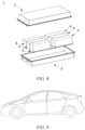
- FIG. 4 shows a prismatic lithium-ion battery 5 as an example.
- the outer package may include a housing 51 and a cover plate 53.
- the housing 51 may include a bottom plate and a side plate connected to the bottom plate. The bottom plate and the side plate close in to form an accommodation cavity.
- the housing 51 is provided with an opening that communicates with the accommodation cavity.
- the cover plate 53 can cover the opening to close the accommodation cavity.
- the positive electrode plate, the negative electrode plate, and the separator may be wound or stacked to form the electrode assembly 52.
- the electrode assembly 52 is packaged in the accommodation cavity.
- the electrolytic solution serves a function of infiltration in the electrode assembly 52.
- the number of electrode assemblies 52 in a lithium-ion battery 5 may be one or more, and may be selected by a person skilled in the art as actually required.
- the lithium-ion battery according to a first aspect of this application may be assembled into a battery module.
- the battery module may include one or more lithium-ion batteries, and the specific number of lithium-ion batteries in a battery module may be selected by a person skilled in the art depending on practical applications and capacity of the battery module.
- FIG. 6 shows a battery module 4 as an example.
- a plurality of lithium-ion batteries 5 may be arranged sequentially along a length direction of the battery module 4.
- the secondary batteries may be arranged in any other manner.
- the plurality of lithium-ion batteries 5 may be fixed by a fastener.
- the battery module 4 may further include a shell that provides an accommodation space.
- the plurality of lithium-ion batteries 5 are accommodated in the accommodation space.
- the battery modules according to this application may be assembled into a battery pack.
- the number of battery modules contained in a battery pack may be selected by a person skilled in the art depending on practical applications and capacity of the battery pack.
- FIG. 7 and FIG. 8 show a battery pack 1 as an example.
- the battery pack 1 may contain a battery box and a plurality of battery modules 4 disposed in the battery box.
- the battery box includes an upper box 2 and a lower box 3.
- the upper box 2 fits the lower box 3 to form a closed space for accommodating the battery modules 4.
- the plurality of battery modules 4 may be arranged in the battery box in any manner.
- the electrical device includes at least one of the lithium-ion battery, the battery module, or the battery pack according to this application.
- the lithium-ion battery, the battery module, or the battery pack may be used as a power supply of the device, or used as an energy storage unit of the device.
- the device may be, but is not limited to, a mobile device (such as a mobile phone or a laptop computer), an electric vehicle (such as a battery electric vehicle, a hybrid electric vehicle, a plug-in hybrid electric vehicle, an electric bicycle, an electric scooter, an electric golf cart, or an electric truck), an electric train, a ship, a satellite system, or an energy storage system.
- the lithium-ion battery, the battery module, or the battery pack may be selected for the electrical device according to practical requirements.
- FIG. 9 shows a device as an example.
- the device may be battery electric vehicle, a hybrid electric vehicle, a plug-in hybrid electric vehicle, or the like.
- a battery pack or a battery module may be used for the device.
- the device may be a mobile phone, a tablet computer, a notebook computer, or the like.
- the device is generally required to be thin and light, and may use a lithium-ion battery as a power supply.
- Lithium-ion batteries in Embodiments 1 to 26 and Comparative Embodiments 1 to 4 are prepared by the following method.
- the current collector 1 is a conventional aluminum current collector, that is, aluminum metal foil.
- the current collectors 2 to 12 are prepared by the following method: Placing a surface-cleaned support layer (PET, with an elastic modulus of 4600 MPa) into a vacuum chamber. Melting and evaporating a high-purity aluminum filament in an aluminum metal evaporation chamber at a temperature of 1500 °C. Cooling the evaporated aluminum metal in a cooling system inside the vacuum chamber, and finally, depositing the aluminum on both surfaces of the support layer to form conductive layers of different thicknesses by controlling the deposition time in a way shown in Table A below.
- PET surface-cleaned support layer
- LiNi 0.8 Mn 0.1 Co 0.1 O 2 as a positive active material
- carbon black (Super P) as a conductive agent
- PVDF polyvinylidene difluoride
- NMP N-methyl-pyrrolidone
- SBR styrene butadiene rubber
- CMC sodium carboxymethyl cellulose
- the electrode assemblies in Comparative Embodiments 1 to 4, Embodiments 1 to 7, and Embodiments 10 to 26 are designed as follows:
- the thickness of a negative current collector copper foil is 6 ⁇ m; the negative current collector is coated with a negative electrode material on both sides, and then cold-pressed; the thickness of the negative electrode plate is 140 ⁇ m; the thickness of a positive current collector is 13 ⁇ m; the positive current collector is coated with a positive electrode material on both sides, and then cold-pressed; the thickness of the positive electrode plate is 114 ⁇ m; and the thickness of the separator is 7 ⁇ m.
- the separator is wound for half a cycle, then the negative electrode plate is inserted and wound for one cycle, and then the positive electrode plate is inserted and wound together.
- a 0.4 MPa pressure roller is applied during the winding to obtain a corresponding electrode assembly.
- the electrode assembly in Embodiment 8 is designed as follows: The thickness of a negative copper foil substrate is 6 ⁇ m; the copper foil is coated with a negative electrode material on both sides, and then cold-pressed; the thickness of the negative electrode plate is 140 ⁇ m; the thickness of a positive aluminum foil substrate is 13 ⁇ m; the aluminum foil is coated with a positive electrode material on both sides, and then cold-pressed; the thickness of the positive electrode plate is 114 ⁇ m; and the thickness of the separator is 9 ⁇ m. First, the separator is wound for one cycle, then the negative electrode plate is inserted and wound for one cycle, and then the positive electrode plate is inserted and wound together. A 0.8 MPa pressure roller is applied during the winding to finally obtain a corresponding electrode assembly.
- the electrode assembly in Embodiment 9 is designed as follows: The thickness of a negative copper foil substrate is 6 ⁇ m; the copper foil is coated with a negative electrode material on both sides, and then cold-pressed; the thickness of the negative electrode plate is 140 ⁇ m; the thickness of a positive aluminum foil substrate is 13 ⁇ m; the aluminum foil is coated with a positive electrode material on both sides, and then cold-pressed; the thickness of the positive electrode plate is 114 ⁇ m; and the thickness of the separator is 9 ⁇ m. First, the separator is wound for 10 cycles, then the negative electrode plate is inserted and wound for one cycle, and then the positive electrode plate is inserted and wound together. A 0.4 MPa pressure roller is used during the winding to finally obtain a corresponding electrode assembly.
- Preparing a separator A conventional polypropylene film is used as a separator.
- the thickness of the separator in Comparative Embodiments 1 to 4, Embodiments 1 to 7, and Embodiments 10 to 28 is 7 ⁇ m, and the thickness of the separator in Embodiments 8 and 9 is 9 ⁇ m.
- the preparation method is: placing an electrode assembly in a housing, drying, injecting an electrolytic solution, and then performing steps such as chemical formation and standing to make a lithium-ion battery.
- the following describes a test process of performance indicators of the lithium-ion battery.
- the evaluation criteria based on the observation are as follows.
- Slight lithium plating At the corner region, the surface of the negative electrode when fully charged is dark yellow. When the surface is wiped with dust-free paper, gray metal lithium powder is left on the paper.
- Average lithium plating At the corner region, the surface of the negative electrode when fully charged is locally gray, without golden yellow.
- Embodiments 1 to 18 by using the electrolytic solution containing the first lithium salt, the corner lithium plating of the convex surface of the negative electrode can be improved effectively. Further, as can be seen from the data of Embodiments 1 to 18, the relationship between w and ⁇ exerts a great impact on the volumetric energy density of lithium-ion battery, the corner lithium plating of the convex surface of the negative electrode, and the internal resistance of the lithium-ion battery. In addition, as can be seen from Table 1, Table 2, and Table 3, when the dosage of the first lithium salt is moderate, the internal resistance of the lithium-ion battery under a normal temperature is ensured to be appropriate. In addition, as can be seen from Table 1, Table 2, and Table 3, the electrolytic solution containing the first lithium salt further improves the high-temperature cycle performance of the lithium-ion battery.
- the current collector and the first lithium salt according to embodiments of this application are lacking, that is, the conventional positive electrode plate and lithium salt LiPF 6 are used in the battery.
- the temperature of the battery soars up by several hundred degrees, and the voltage plummets to zero. This shows that, at the instant of penetration, the battery incurs an internal short circuit, and generates a lot of heat.
- the battery is thermally runaway and destroyed in an instant, and fails to work.
- the thickness ⁇ 1 (measured in ⁇ m) of the metallic conductive layer of the positive current collector is 0.52 to 2.4, preferably 0.55 to 2, and more preferably 0.8 to 1.3.
- the thickness of the metallic conductive layer is controlled to fall within such a range that the resistance of the positive current collector is moderate, thereby achieving both a long cycle life and a high mass energy density.
- Embodiment 13 in Table 2 although the corner lithium plating on the convex surface can be suppressed, because the current collector is relatively thick, the percentage of inactive materials in the lithium-ion battery is higher, and therefore, the mass energy density of the lithium-ion battery is lower.
- the mass fraction of the first lithium salt in the electrolytic solution is preferably 5% to 30%, more preferably 6% to 25%, and further preferably 11% to 20%.
- Embodiment 18 in Table 3 if the content of the first lithium salt is relatively high, on the one hand, the electrolytic solution is relatively inferior in both kinetics and film formation quality, thereby resulting in slight lithium plating on the convex surface at the corner, and in turn, deteriorating the hot-oven safety performance and cycle performance.
Landscapes
- Chemical & Material Sciences (AREA)
- General Chemical & Material Sciences (AREA)
- Chemical Kinetics & Catalysis (AREA)
- Electrochemistry (AREA)
- Engineering & Computer Science (AREA)
- Manufacturing & Machinery (AREA)
- Composite Materials (AREA)
- General Physics & Mathematics (AREA)
- Inorganic Chemistry (AREA)
- Condensed Matter Physics & Semiconductors (AREA)
- Physics & Mathematics (AREA)
- Materials Engineering (AREA)
- Secondary Cells (AREA)
- Cell Electrode Carriers And Collectors (AREA)
- Battery Electrode And Active Subsutance (AREA)
Priority Applications (1)
| Application Number | Priority Date | Filing Date | Title |
|---|---|---|---|
| EP23210059.4A EP4300652A3 (de) | 2021-08-31 | 2021-08-31 | Lithium-ionen-batterie, batteriemodul, batteriepack und elektrische vorrichtung |
Applications Claiming Priority (3)
| Application Number | Priority Date | Filing Date | Title |
|---|---|---|---|
| EP21931920.9A EP4170758A4 (de) | 2021-08-31 | 2021-08-31 | Lithium-ionen-batterie, batteriemodul, batteriepack und elektrische vorrichtung |
| EP23210059.4A EP4300652A3 (de) | 2021-08-31 | 2021-08-31 | Lithium-ionen-batterie, batteriemodul, batteriepack und elektrische vorrichtung |
| PCT/CN2021/115815 WO2023028888A1 (zh) | 2021-08-31 | 2021-08-31 | 一种锂离子电池、电池模块、电池包及用电装置 |
Related Parent Applications (1)
| Application Number | Title | Priority Date | Filing Date |
|---|---|---|---|
| EP21931920.9A Division EP4170758A4 (de) | 2021-08-31 | 2021-08-31 | Lithium-ionen-batterie, batteriemodul, batteriepack und elektrische vorrichtung |
Publications (2)
| Publication Number | Publication Date |
|---|---|
| EP4300652A2 true EP4300652A2 (de) | 2024-01-03 |
| EP4300652A3 EP4300652A3 (de) | 2024-06-19 |
Family
ID=85411840
Family Applications (2)
| Application Number | Title | Priority Date | Filing Date |
|---|---|---|---|
| EP21931920.9A Pending EP4170758A4 (de) | 2021-08-31 | 2021-08-31 | Lithium-ionen-batterie, batteriemodul, batteriepack und elektrische vorrichtung |
| EP23210059.4A Pending EP4300652A3 (de) | 2021-08-31 | 2021-08-31 | Lithium-ionen-batterie, batteriemodul, batteriepack und elektrische vorrichtung |
Family Applications Before (1)
| Application Number | Title | Priority Date | Filing Date |
|---|---|---|---|
| EP21931920.9A Pending EP4170758A4 (de) | 2021-08-31 | 2021-08-31 | Lithium-ionen-batterie, batteriemodul, batteriepack und elektrische vorrichtung |
Country Status (4)
| Country | Link |
|---|---|
| US (3) | US12424618B2 (de) |
| EP (2) | EP4170758A4 (de) |
| CN (1) | CN116982177A (de) |
| WO (1) | WO2023028888A1 (de) |
Families Citing this family (4)
| Publication number | Priority date | Publication date | Assignee | Title |
|---|---|---|---|---|
| JP1775609S (ja) * | 2023-03-03 | 2024-07-17 | 電池、電動 | |
| JP1776702S (ja) * | 2023-12-05 | 2024-07-30 | 電池ケース | |
| JP1776653S (ja) * | 2023-12-05 | 2024-07-30 | 電池ケース | |
| JP1776701S (ja) * | 2023-12-05 | 2024-07-30 | 電池ケース |
Family Cites Families (9)
| Publication number | Priority date | Publication date | Assignee | Title |
|---|---|---|---|---|
| KR100337707B1 (ko) * | 2000-09-25 | 2002-05-22 | 정근창 | 포케팅 전극체 및 그 제조방법과 이를 이용한 리튬이온이차전지 |
| US8236441B2 (en) * | 2007-07-24 | 2012-08-07 | A123 Systems, Inc. | Battery cell design and methods of its construction |
| EP2466668B1 (de) * | 2009-08-14 | 2014-10-22 | LG Chem, Ltd. | Zylinderförmige wiederaufladbare batterie von erhöhter stabilität |
| CN107123812B (zh) | 2017-04-14 | 2020-05-19 | 宁德时代新能源科技股份有限公司 | 一种正极集流体、其制备方法及其应用 |
| CN110943227B (zh) | 2019-05-31 | 2021-03-09 | 宁德时代新能源科技股份有限公司 | 复合集流体、电极极片及电化学装置 |
| CN111180737B (zh) | 2019-05-31 | 2021-08-03 | 宁德时代新能源科技股份有限公司 | 锂离子二次电池、电芯及负极极片 |
| CN112186197B (zh) * | 2019-07-01 | 2024-06-18 | 宁德时代新能源科技股份有限公司 | 正极集流体、正极极片及电化学装置 |
| CN115039253B (zh) * | 2020-02-19 | 2025-06-20 | 松下新能源株式会社 | 非水电解质二次电池及非水电解质二次电池用负极 |
| CN111934027A (zh) * | 2020-08-27 | 2020-11-13 | 东莞市创明电池技术有限公司 | 圆柱锂电池卷芯及圆柱锂电池 |
-
2021
- 2021-08-31 WO PCT/CN2021/115815 patent/WO2023028888A1/zh not_active Ceased
- 2021-08-31 CN CN202180095420.0A patent/CN116982177A/zh active Pending
- 2021-08-31 EP EP21931920.9A patent/EP4170758A4/de active Pending
- 2021-08-31 EP EP23210059.4A patent/EP4300652A3/de active Pending
-
2022
- 2022-09-27 US US17/953,327 patent/US12424618B2/en active Active
-
2023
- 2023-12-14 US US18/539,282 patent/US20240113287A1/en active Pending
-
2025
- 2025-08-08 US US19/294,365 patent/US20250364544A1/en active Pending
Also Published As
| Publication number | Publication date |
|---|---|
| EP4170758A4 (de) | 2023-09-06 |
| US20230084934A1 (en) | 2023-03-16 |
| WO2023028888A1 (zh) | 2023-03-09 |
| EP4300652A3 (de) | 2024-06-19 |
| US12424618B2 (en) | 2025-09-23 |
| CN116982177A (zh) | 2023-10-31 |
| EP4170758A1 (de) | 2023-04-26 |
| US20240113287A1 (en) | 2024-04-04 |
| US20250364544A1 (en) | 2025-11-27 |
Similar Documents
| Publication | Publication Date | Title |
|---|---|---|
| EP3951958B1 (de) | Positiver stromabnehmer, positive elektrodenplatte, sekundärbatterie und vorrichtung | |
| US11476469B2 (en) | Negative current collector, negative electrode plate, electrochemical device, and apparatus | |
| EP3913711B1 (de) | Elektrodenplatte, elektrochemische vorrichtung und vorrichtung dafür | |
| EP3923388B1 (de) | Elektrodenfolien, elektrochemische vorrichtung und vorrichtung | |
| US12424618B2 (en) | Lithium-ion battery, battery module, battery pack, and electrical device | |
| EP3796436B1 (de) | Elektrodenplatte, elektrochemische vorrichtung, batteriemodul, batteriesatz und einrichtung | |
| EP3930035B1 (de) | Elektrodenpolstück, elektrochemische vorrichtung | |
| EP3930055B1 (de) | Elektrodenplatte, elektrochemische vorrichtung und vorrichtung | |
| US12444751B2 (en) | Positive current collector, positive electrode plate, battery, and apparatus | |
| EP3799169B1 (de) | Elektrodenplatte, elektrochemisches gerät, batteriemodul, batteriepack und vorrichtung | |
| EP3796435A1 (de) | Elektrodenplatte, elektrochemische vorrichtung, batteriemodul, batteriesatz und einrichtung | |
| EP3930053B1 (de) | Positives polstück, elektrochemische vorrichtung und vorrichtung | |
| EP1826862B1 (de) | Sekundärbatterie mit nichtwässrigen Elektrolyten | |
| US12261319B2 (en) | Battery module, battery pack, electrical apparatus, and manufacturing method and manufacturing device of battery module | |
| EP4109602B1 (de) | Positivelektrodenstromkollektor und positivelektrodenplatte, batterie, batteriemodul, batteriepack und vorrichtung damit | |
| EP4148821A1 (de) | Sekundärbatterie und vorrichtung mit der sekundärbatterie | |
| US20220123322A1 (en) | Positive current collector, positive plate, electrochemical device and apparatus | |
| US7824810B2 (en) | Electrolytic solution and battery | |
| EP4167326A1 (de) | Positivelektrodenkollektor, sekundärbatterie und elektrische vorrichtung | |
| US20040081891A1 (en) | Nonaqueous electrolyte secondary cell | |
| KR20240160198A (ko) | 전지, 이의 제조 방법 및 이를 포함하는 전기 장치 |
Legal Events
| Date | Code | Title | Description |
|---|---|---|---|
| PUAI | Public reference made under article 153(3) epc to a published international application that has entered the european phase |
Free format text: ORIGINAL CODE: 0009012 |
|
| STAA | Information on the status of an ep patent application or granted ep patent |
Free format text: STATUS: REQUEST FOR EXAMINATION WAS MADE |
|
| 17P | Request for examination filed |
Effective date: 20231115 |
|
| AC | Divisional application: reference to earlier application |
Ref document number: 4170758 Country of ref document: EP Kind code of ref document: P |
|
| AK | Designated contracting states |
Kind code of ref document: A2 Designated state(s): AL AT BE BG CH CY CZ DE DK EE ES FI FR GB GR HR HU IE IS IT LI LT LU LV MC MK MT NL NO PL PT RO RS SE SI SK SM TR |
|
| REG | Reference to a national code |
Ref country code: DE Ref legal event code: R079 Free format text: PREVIOUS MAIN CLASS: H01M0010056800 Ipc: H01M0004660000 |
|
| PUAL | Search report despatched |
Free format text: ORIGINAL CODE: 0009013 |
|
| AK | Designated contracting states |
Kind code of ref document: A3 Designated state(s): AL AT BE BG CH CY CZ DE DK EE ES FI FR GB GR HR HU IE IS IT LI LT LU LV MC MK MT NL NO PL PT RO RS SE SI SK SM TR |
|
| RIC1 | Information provided on ipc code assigned before grant |
Ipc: H01M 4/62 20060101ALI20240516BHEP Ipc: H01M 4/36 20060101ALI20240516BHEP Ipc: H01M 10/0568 20100101ALI20240516BHEP Ipc: H01M 10/0567 20100101ALI20240516BHEP Ipc: H01M 10/0525 20100101ALI20240516BHEP Ipc: H01M 10/0587 20100101ALI20240516BHEP Ipc: H01M 4/66 20060101AFI20240516BHEP |
|
| RAP1 | Party data changed (applicant data changed or rights of an application transferred) |
Owner name: CONTEMPORARY AMPEREX TECHNOLOGY(HONG KONG) LIMITED |