EP4300642A1 - Flexible battery and method for manufacturing same - Google Patents
Flexible battery and method for manufacturing same Download PDFInfo
- Publication number
- EP4300642A1 EP4300642A1 EP21928465.0A EP21928465A EP4300642A1 EP 4300642 A1 EP4300642 A1 EP 4300642A1 EP 21928465 A EP21928465 A EP 21928465A EP 4300642 A1 EP4300642 A1 EP 4300642A1
- Authority
- EP
- European Patent Office
- Prior art keywords
- anode
- cathode
- electrical connector
- plates
- flexible battery
- Prior art date
- Legal status (The legal status is an assumption and is not a legal conclusion. Google has not performed a legal analysis and makes no representation as to the accuracy of the status listed.)
- Pending
Links
- 238000004519 manufacturing process Methods 0.000 title claims abstract description 22
- 238000000034 method Methods 0.000 title claims description 16
- 238000005520 cutting process Methods 0.000 claims abstract description 19
- 238000004804 winding Methods 0.000 claims abstract description 15
- 239000011888 foil Substances 0.000 claims description 51
- 239000011248 coating agent Substances 0.000 claims description 17
- 238000000576 coating method Methods 0.000 claims description 17
- 238000003466 welding Methods 0.000 claims description 16
- 239000012785 packaging film Substances 0.000 claims description 15
- 229920006280 packaging film Polymers 0.000 claims description 15
- 238000005452 bending Methods 0.000 claims description 13
- 238000003698 laser cutting Methods 0.000 claims description 4
- 238000004806 packaging method and process Methods 0.000 claims description 3
- 238000005516 engineering process Methods 0.000 abstract description 2
- 238000010586 diagram Methods 0.000 description 6
- 239000005022 packaging material Substances 0.000 description 6
- 238000003825 pressing Methods 0.000 description 4
- XAGFODPZIPBFFR-UHFFFAOYSA-N aluminium Chemical compound [Al] XAGFODPZIPBFFR-UHFFFAOYSA-N 0.000 description 3
- 238000004080 punching Methods 0.000 description 3
- RYGMFSIKBFXOCR-UHFFFAOYSA-N Copper Chemical compound [Cu] RYGMFSIKBFXOCR-UHFFFAOYSA-N 0.000 description 2
- PXHVJJICTQNCMI-UHFFFAOYSA-N Nickel Chemical compound [Ni] PXHVJJICTQNCMI-UHFFFAOYSA-N 0.000 description 2
- 239000000853 adhesive Substances 0.000 description 2
- 230000001070 adhesive effect Effects 0.000 description 2
- 229910052782 aluminium Inorganic materials 0.000 description 2
- 239000010405 anode material Substances 0.000 description 2
- 239000010406 cathode material Substances 0.000 description 2
- 239000007769 metal material Substances 0.000 description 2
- 238000012986 modification Methods 0.000 description 2
- 230000004048 modification Effects 0.000 description 2
- 238000006467 substitution reaction Methods 0.000 description 2
- OKTJSMMVPCPJKN-UHFFFAOYSA-N Carbon Chemical compound [C] OKTJSMMVPCPJKN-UHFFFAOYSA-N 0.000 description 1
- WHXSMMKQMYFTQS-UHFFFAOYSA-N Lithium Chemical compound [Li] WHXSMMKQMYFTQS-UHFFFAOYSA-N 0.000 description 1
- 239000011889 copper foil Substances 0.000 description 1
- 230000014509 gene expression Effects 0.000 description 1
- 239000010439 graphite Substances 0.000 description 1
- 229910002804 graphite Inorganic materials 0.000 description 1
- 239000011810 insulating material Substances 0.000 description 1
- 238000009413 insulation Methods 0.000 description 1
- 229910052744 lithium Inorganic materials 0.000 description 1
- GELKBWJHTRAYNV-UHFFFAOYSA-K lithium iron phosphate Chemical compound [Li+].[Fe+2].[O-]P([O-])([O-])=O GELKBWJHTRAYNV-UHFFFAOYSA-K 0.000 description 1
- 239000000463 material Substances 0.000 description 1
- 229910052751 metal Inorganic materials 0.000 description 1
- 239000002184 metal Substances 0.000 description 1
- 229910052759 nickel Inorganic materials 0.000 description 1
- 229920006255 plastic film Polymers 0.000 description 1
- 239000002985 plastic film Substances 0.000 description 1
- 238000007789 sealing Methods 0.000 description 1
- 229910052710 silicon Inorganic materials 0.000 description 1
- 239000010703 silicon Substances 0.000 description 1
Images


Classifications
-
- H—ELECTRICITY
- H01—ELECTRIC ELEMENTS
- H01M—PROCESSES OR MEANS, e.g. BATTERIES, FOR THE DIRECT CONVERSION OF CHEMICAL ENERGY INTO ELECTRICAL ENERGY
- H01M50/00—Constructional details or processes of manufacture of the non-active parts of electrochemical cells other than fuel cells, e.g. hybrid cells
- H01M50/20—Mountings; Secondary casings or frames; Racks, modules or packs; Suspension devices; Shock absorbers; Transport or carrying devices; Holders
- H01M50/204—Racks, modules or packs for multiple batteries or multiple cells
- H01M50/207—Racks, modules or packs for multiple batteries or multiple cells characterised by their shape
- H01M50/211—Racks, modules or packs for multiple batteries or multiple cells characterised by their shape adapted for pouch cells
-
- H—ELECTRICITY
- H01—ELECTRIC ELEMENTS
- H01M—PROCESSES OR MEANS, e.g. BATTERIES, FOR THE DIRECT CONVERSION OF CHEMICAL ENERGY INTO ELECTRICAL ENERGY
- H01M10/00—Secondary cells; Manufacture thereof
- H01M10/04—Construction or manufacture in general
- H01M10/0436—Small-sized flat cells or batteries for portable equipment
-
- H—ELECTRICITY
- H01—ELECTRIC ELEMENTS
- H01M—PROCESSES OR MEANS, e.g. BATTERIES, FOR THE DIRECT CONVERSION OF CHEMICAL ENERGY INTO ELECTRICAL ENERGY
- H01M10/00—Secondary cells; Manufacture thereof
- H01M10/04—Construction or manufacture in general
-
- H—ELECTRICITY
- H01—ELECTRIC ELEMENTS
- H01M—PROCESSES OR MEANS, e.g. BATTERIES, FOR THE DIRECT CONVERSION OF CHEMICAL ENERGY INTO ELECTRICAL ENERGY
- H01M10/00—Secondary cells; Manufacture thereof
- H01M10/04—Construction or manufacture in general
- H01M10/0431—Cells with wound or folded electrodes
-
- H—ELECTRICITY
- H01—ELECTRIC ELEMENTS
- H01M—PROCESSES OR MEANS, e.g. BATTERIES, FOR THE DIRECT CONVERSION OF CHEMICAL ENERGY INTO ELECTRICAL ENERGY
- H01M10/00—Secondary cells; Manufacture thereof
- H01M10/05—Accumulators with non-aqueous electrolyte
- H01M10/058—Construction or manufacture
- H01M10/0583—Construction or manufacture of accumulators with folded construction elements except wound ones, i.e. folded positive or negative electrodes or separators, e.g. with "Z"-shaped electrodes or separators
-
- H—ELECTRICITY
- H01—ELECTRIC ELEMENTS
- H01M—PROCESSES OR MEANS, e.g. BATTERIES, FOR THE DIRECT CONVERSION OF CHEMICAL ENERGY INTO ELECTRICAL ENERGY
- H01M10/00—Secondary cells; Manufacture thereof
- H01M10/05—Accumulators with non-aqueous electrolyte
- H01M10/058—Construction or manufacture
- H01M10/0587—Construction or manufacture of accumulators having only wound construction elements, i.e. wound positive electrodes, wound negative electrodes and wound separators
-
- H—ELECTRICITY
- H01—ELECTRIC ELEMENTS
- H01M—PROCESSES OR MEANS, e.g. BATTERIES, FOR THE DIRECT CONVERSION OF CHEMICAL ENERGY INTO ELECTRICAL ENERGY
- H01M50/00—Constructional details or processes of manufacture of the non-active parts of electrochemical cells other than fuel cells, e.g. hybrid cells
- H01M50/10—Primary casings; Jackets or wrappings
- H01M50/102—Primary casings; Jackets or wrappings characterised by their shape or physical structure
- H01M50/105—Pouches or flexible bags
-
- H—ELECTRICITY
- H01—ELECTRIC ELEMENTS
- H01M—PROCESSES OR MEANS, e.g. BATTERIES, FOR THE DIRECT CONVERSION OF CHEMICAL ENERGY INTO ELECTRICAL ENERGY
- H01M50/00—Constructional details or processes of manufacture of the non-active parts of electrochemical cells other than fuel cells, e.g. hybrid cells
- H01M50/10—Primary casings; Jackets or wrappings
- H01M50/131—Primary casings; Jackets or wrappings characterised by physical properties, e.g. gas permeability, size or heat resistance
- H01M50/136—Flexibility or foldability
-
- H—ELECTRICITY
- H01—ELECTRIC ELEMENTS
- H01M—PROCESSES OR MEANS, e.g. BATTERIES, FOR THE DIRECT CONVERSION OF CHEMICAL ENERGY INTO ELECTRICAL ENERGY
- H01M50/00—Constructional details or processes of manufacture of the non-active parts of electrochemical cells other than fuel cells, e.g. hybrid cells
- H01M50/50—Current conducting connections for cells or batteries
- H01M50/502—Interconnectors for connecting terminals of adjacent batteries; Interconnectors for connecting cells outside a battery casing
-
- H—ELECTRICITY
- H01—ELECTRIC ELEMENTS
- H01M—PROCESSES OR MEANS, e.g. BATTERIES, FOR THE DIRECT CONVERSION OF CHEMICAL ENERGY INTO ELECTRICAL ENERGY
- H01M50/00—Constructional details or processes of manufacture of the non-active parts of electrochemical cells other than fuel cells, e.g. hybrid cells
- H01M50/50—Current conducting connections for cells or batteries
- H01M50/502—Interconnectors for connecting terminals of adjacent batteries; Interconnectors for connecting cells outside a battery casing
- H01M50/514—Methods for interconnecting adjacent batteries or cells
- H01M50/516—Methods for interconnecting adjacent batteries or cells by welding, soldering or brazing
-
- H—ELECTRICITY
- H01—ELECTRIC ELEMENTS
- H01M—PROCESSES OR MEANS, e.g. BATTERIES, FOR THE DIRECT CONVERSION OF CHEMICAL ENERGY INTO ELECTRICAL ENERGY
- H01M50/00—Constructional details or processes of manufacture of the non-active parts of electrochemical cells other than fuel cells, e.g. hybrid cells
- H01M50/50—Current conducting connections for cells or batteries
- H01M50/543—Terminals
- H01M50/552—Terminals characterised by their shape
- H01M50/553—Terminals adapted for prismatic, pouch or rectangular cells
- H01M50/557—Plate-shaped terminals
-
- Y—GENERAL TAGGING OF NEW TECHNOLOGICAL DEVELOPMENTS; GENERAL TAGGING OF CROSS-SECTIONAL TECHNOLOGIES SPANNING OVER SEVERAL SECTIONS OF THE IPC; TECHNICAL SUBJECTS COVERED BY FORMER USPC CROSS-REFERENCE ART COLLECTIONS [XRACs] AND DIGESTS
- Y02—TECHNOLOGIES OR APPLICATIONS FOR MITIGATION OR ADAPTATION AGAINST CLIMATE CHANGE
- Y02E—REDUCTION OF GREENHOUSE GAS [GHG] EMISSIONS, RELATED TO ENERGY GENERATION, TRANSMISSION OR DISTRIBUTION
- Y02E60/00—Enabling technologies; Technologies with a potential or indirect contribution to GHG emissions mitigation
- Y02E60/10—Energy storage using batteries
-
- Y—GENERAL TAGGING OF NEW TECHNOLOGICAL DEVELOPMENTS; GENERAL TAGGING OF CROSS-SECTIONAL TECHNOLOGIES SPANNING OVER SEVERAL SECTIONS OF THE IPC; TECHNICAL SUBJECTS COVERED BY FORMER USPC CROSS-REFERENCE ART COLLECTIONS [XRACs] AND DIGESTS
- Y02—TECHNOLOGIES OR APPLICATIONS FOR MITIGATION OR ADAPTATION AGAINST CLIMATE CHANGE
- Y02P—CLIMATE CHANGE MITIGATION TECHNOLOGIES IN THE PRODUCTION OR PROCESSING OF GOODS
- Y02P70/00—Climate change mitigation technologies in the production process for final industrial or consumer products
- Y02P70/50—Manufacturing or production processes characterised by the final manufactured product
Definitions
- This application relates to the field of battery technologies, and in particular, to a flexible battery and a manufacturing method thereof.
- some embodiments of this application provide a flexible battery and a manufacturing method thereof to reduce safety risks in production and improve the utilization of electrode plates.
- a flexible battery including a plurality of cathode plates, a cathode electrical connector, a plurality of anode plates, an anode electrical connector, and a plurality of separators.
- the cathode electrical connector is welded to the plurality of cathode plates
- the anode electrical connector is welded to the plurality of anode plates.
- Each of the anode plates corresponds to one of the cathode plates
- each of the separators is disposed between one corresponding anode plate and one corresponding cathode plate.
- the plurality of cathode plates, the plurality of anode plates, and the plurality of separators are wound on the cathode electrical connector and the anode electrical connector to form a plurality of cell units and spine portions connecting adjacent two of the cell units.
- the cell units are bent, and/or the spine portions are bent.
- the spine portions are of any one of a wavy shape, a sinusoidal shape, a U shape, or a zigzag shape.
- a distance is provided between adjacent two of the cell units.
- the cathode plate includes a first uncoated foil region, a second uncoated foil region, and a first coating region, where the first coating region is located between the first uncoated foil region and the second uncoated foil region, and the cathode electrical connector is welded to the first uncoated foil regions of the plurality of cathode plates.
- the anode plate includes a third uncoated foil region, a fourth uncoated foil region, and a second coating region, where the second coating region is located between the third uncoated foil region and the fourth uncoated foil region, and the anode electrical connector is welded to the third uncoated foil regions of the plurality of anode plates.
- the flexible battery further includes a packaging film, the cell unit being accommodated in the packaging film.
- the cathode electrical connector is provided with a first insulating tape on a surface
- the anode electrical connector is provided with a second insulating tape on a surface
- a manufacturing method of flexible battery includes: sequentially spacing apart a plurality of cathode plates; welding a cathode electrical connector to the plurality of cathode plates to form a first connected structure; sequentially spacing apart a plurality of anode plates; welding an anode electrical connector to the plurality of anode plates to form a second connected structure; sequentially stacking the first connected structure, a first separator, the second connected structure, and a second separator to form a stacked structure; winding the stacked structure; and cutting apart portions, located between adjacent two of the anode plates and between adjacent two of the cathode plates, of the first separator and the second separator, to form a plurality of cell units and spine portions connecting adjacent two of the cell units.
- the method further includes: bending the cell units.
- the method further includes: bending the spine portions.
- the step of bending the spine portions further includes: bending the spine portions into any one of a wavy shape, a sinusoidal shape, a U shape, or a zigzag shape.
- the method further includes: packaging the cell units in a packaging film.
- the step of welding a cathode electrical connector to the plurality of cathode plates to form a first connected structure further includes: welding the cathode electrical connector to the first uncoated foil regions of the plurality of cathode plates to form the first connected structure.
- the step of welding an anode electrical connector to the plurality of anode plates to form a second connected structure further includes: welding the anode electrical connector to the third uncoated foil regions of the plurality of anode plates to form the second connected structure.
- the plurality of cathode plates and the cathode electrical connector are laser-welded or ultrasonically welded.
- the plurality of anode plates and the anode electrical connector are laser-welded or ultrasonically welded.
- the portions, located between adjacent two of the anode plates, of the first separator and the second separator are cut apart using a laser cutting or die cutting process.
- the method further includes: adhering a first insulating tape to each of two surfaces of the cathode electrical connector, and adhering a second insulating tape to each of two surfaces of the anode electrical connector.
- the plurality of cathode plates are welded to the cathode electrical connector; the plurality of anode plates are welded to the anode electrical connector; the plurality of cathode plates, the plurality of anode plates, and the plurality of separators are wound to form the plurality of cell units; and the portions, located between adjacent two of the cell units, of the cathode electrical connector and the anode electrical connector form the spine portions.
- the cathode plates and the anode plates are already in a strip structure and therefore need no cutting for winding, thereby avoiding generation of burrs and lumps, reducing safety risks in production, and improving utilization of electrode plates.
- an embodiment of this application provides a flexible battery 100 including cathode plates 10, anode plates 20, a cathode electrical connector 30, an anode electrical connector 40, and separators 50.
- cathode plates 10, anode plates 20, a cathode electrical connector 30, an anode electrical connector 40, and separators 50 There are a plurality of cathode plates 10, a plurality of anode plates 20, and a plurality of separators 50.
- Each of the cathode plates 10 corresponds to one of the anode plates 20, and each of the separators 50 is disposed between one corresponding cathode plate 10 and one corresponding anode plate 20.
- the plurality of cathode plates 10 are welded to the cathode electrical connector 30, and the plurality of anode plates 20 are welded to the anode electrical connector 40.
- the plurality of cathode plates 10, the plurality of anode plates 20, and the plurality of separators 50 are wound on the cathode electrical connector 30 and the anode electrical connector 40 to form a plurality of cell units 101 and spine portions 102 connecting adjacent two of the cell units 101.
- the cathode plate 10 is a strip sheet structure, and the cathode plate 10 includes a current collector and a cathode material applied on the current collector, where the current collector of the cathode plate 10 may be an aluminum foil, and the cathode material may be lithium cobaltate, lithium iron phosphate, a ternary material, or the like. Any surface of the cathode plate 10 is divided into a first uncoated foil region 11, a second uncoated foil region 12, and a first coating region 13 according to preset positions.
- the first uncoated foil region 11 and the second uncoated foil region 12 are respectively disposed at two ends of the cathode plate 10 in a length direction of the cathode plate 10, and the first coating region 13 is disposed between the first uncoated foil region 11 and the second uncoated foil region 12.
- the plurality of cathode plates 10 are spaced apart sequentially.
- the cathode electrical connector 30 is welded to the first uncoated foil regions 11 of the plurality of cathode plates 10 to form a first connected structure A1.
- the cathode electrical connector 30 and the plurality of cathode plates 10 may be connected by laser welding, ultrasonic welding, or the like.
- the anode plate 20 is similar to the cathode plate 10 in structure.
- the anode plate 20 is a strip sheet structure, and the anode plate 20 includes a current collector and an anode material applied on the current collector, where the current collector of the anode plate 20 may be a copper foil, and the anode material may be graphite, silicon, or the like. Any surface of the anode plate 20 is divided into a third uncoated foil region 21, a fourth uncoated foil region 22, and a second coating region 23 according to preset positions.
- the third uncoated foil region 21 and the fourth uncoated foil region 22 are respectively disposed at two ends of the anode plate 20 in a length direction of the anode plate 20, and the second coating region 23 is disposed between the third uncoated foil region 21 and the fourth uncoated foil region 22.
- the plurality of anode plates 20 are spaced apart sequentially.
- the anode electrical connector 40 is welded to the third uncoated foil regions 21 of the plurality of anode plates 20 to form a second connected structure A2.
- the anode electrical connector 40 and the plurality of anode plates 20 may be connected by laser welding, ultrasonic welding, or the like.
- the cathode electrical connector 30 is made of a metal material.
- the cathode electrical connector 30 is a strip structure or a wire structure.
- the cathode electrical connector 30 may be an aluminum metal strip, a copper wire, or the like.
- the cathode electrical connector 30 extends along an arrangement direction of the plurality of cathode plates 10.
- An end of the cathode electrical connector 30 extends out of the plurality of cathode plates 10.
- the end of the cathode electrical connector 30 extending out of the plurality of cathode plates 10 serves as a positive tab of the flexible battery 100, and a joint between the positive tab and the cathode plate 10 is provided with a tab adhesive (not shown in the figure).
- the anode electrical connector 40 is made of a metal material.
- the anode electrical connector 40 may be a strip structure or a wire structure.
- the anode electrical connector 40 may be a nickel metal strip, an aluminum wire, or the like.
- the anode electrical connector 40 extends along an arrangement direction of the plurality of anode plates 20.
- An end of the anode electrical connector 40 extends out of the plurality of anode plates 20.
- the end of the anode electrical connector 40 extending out of the plurality of anode plates 20 serves as a negative tab of the flexible battery 100, and a joint between the negative tab and the anode plate 20 is provided with a tab adhesive (not shown in the figure).
- a first insulating tape is adhered to each of two surfaces of the cathode electrical connector 30 (not shown in the figure) to form the first connected structure A1; and after the anode electrical connector 40 and the plurality of anode plates 20 are welded, a second insulating tape is adhered to each of two surfaces of the anode electrical connector 40 (not shown in the figure) to form the second connected structure A2, thereby preventing the cathode electrical connector 30 and the anode electrical connector 40 from puncturing the cathode plates 10, the anode plates 20, and the separators 50 during winding, and also providing insulation for the spine portions 102.
- the separator 50 is a strip sheet structure made of an insulating material, and the separator 50 is formed by cutting a complete piece of separator.
- the complete piece of separator is wound on the cathode electrical connector 30 and the anode electrical connector 40 and is then cut apart or partially cut apart to form a plurality of separators 50.
- two complete pieces of separators are provided, which are a first separator A3 and a second separator A4, respectively.
- the first connected structure A1, a complete piece of the first separator A3, the second connected structure A2, and a complete piece of the second separator A4 are first wound using a winding machine to form an integrated structure, and then needless parts of the first separator A3 and second separator A4 are cut apart using a laser cutting process or a mechanism such as a cutting die.
- the first connected structure A1, the first separator A3, the second connected structure A2, and the second separator A4 are sequentially stacked in a guide groove of the winding machine, each of the cathode plates 10 corresponds to one of the anode plates 20 in position, and the cathode electrical connector 30 corresponds to the anode electrical connector 40 in position, thereby guaranteeing parallelism of the cathode plate 10 and the anode plate 20 before winding and during winding; the first uncoated foil region 11 and the third uncoated foil region 21 serve as the head of winding, and the first connected structure A1, a complete piece of the first separator A3, the second connected structure A2, and a complete piece of the second separator A4 are wound using the winding machine to form an integrated structure (shown in FIG.
- a cathode plate 10, an anode plate 20, a separator 50 formed by cutting the first separator A3, and a separator 50 formed by cutting the second separator A4 are wound to form a cell unit 101. Portions, located between adjacent two of the cell units 101, of the cathode electrical connector 30 and the anode electrical connector 40 form spine portions 102.
- a distance is provided between adjacent two of the cell units 101, so as to ensure that the separators 50 formed by cutting apart the first separator A3 and the second separator A4 do not shrink into the cell units 101.
- the distance is set based on thickness of the battery and a required bending angle of the battery.
- the bending angle of the battery is typically not greater than 90 degrees, and the distance is typically not less than the thickness of the battery.
- the thickness of the battery is thickness of the cell unit 101, and the bending angle of the battery is an included angle between adjacent two of the cell units 101.
- the cell units 101 are set to be bent, thereby improving flexibility of joints of the battery, and reducing a tensile stress from the cathode electrical connector 30 and the anode electrical connector 40 to the cell units 101.
- the cell units 101 can be bent using a mold pressing process, so that two ends of a cell unit 101 connected to the spine portions 102 are both bent relative to a central portion of the cell unit 101 to form an arc shape, thereby obtaining a required bending radian.
- the spine portions 102 are set to be bent, and the spine portions 102 may be of a wavy shape, a sinusoidal shape, a U shape, a zigzag shape, or another specially-structured shape.
- the spine portions 102 are bent using a mold-pressing process, and then the plurality of cell units 101 are integrally bent, thereby reducing a stress of the cell units 101 in a stretching state during integral mold pressing.
- the flexible battery 100 further includes a packaging film 103, the cell units 101 are accommodated in the packaging film 103.
- the packaging film 103 may wrap only the cell units 101.
- the packaging film 103 may integrally wrap the cell units 101 and the spine portions 102.
- the packaging film 103 separately wraps the cell units 101 and the spine portions 102. This is not limited herein.
- the packaging film 103 may be formed by performing integral packaging with a packaging material, for example, the packaging material is heat-sealed outside the cell unit 101 to form the packaging film 103.
- the packaging film 103 may be formed by performing pit punching on a packaging material, for example, the packaging material is subjected to pit punching according to an overall shape of the cell units 101 and the spine portions 102, and then the cell units 101 and the spine portions 102 are integrally encapsulated in a housing.
- the packaging material may be an aluminum-plastic film.
- the cathode electrical connector 30 and the first uncoated foil regions 11 of the plurality of cathode plates 10 are laser-welded or ultrasonically welded, and then a first insulating tape is adhered to each of two surfaces of the cathode electrical connector 30 to form the first connected structure A1;
- the anode electrical connector 40 and the third uncoated foil regions 21 of the plurality of anode plates 20 are laser-welded or ultrasonically welded, and then a second insulating tape is adhered to each of two surfaces of the anode electrical connector 40 to form the second connected structure A2;
- the first connected structure A1, the first separator A3, the second connected structure A2, and the second separator A4 are sequentially stacked and then wound using a winding machine to form an integrated structure;
- the first separator A3, the plurality of first separators A4, located between adjacent two of the anode plates and between adjacent two of the cathode plates are cut apart using a laser cutting process or a mechanism such as a cutting die;
- the cathode plates 10 and the anode plates 20 are already in a required strip structure before coating and therefore need no cutting for winding, thereby avoiding generation of burrs and lumps, reducing safety risks in production, and improving utilization of electrode plates.
- the first separator A3 and the second separator A4 are complete pieces of separators disposed between the plurality of cathode plates 10 and the plurality of anode plates 20, so that the plurality of cathode plates 10 and the plurality of anode plates 20 are integrally wound and molded, improving the production efficiency.
- an end of the cathode electrical connector 30 protruding from the cathode plate 10 can serve as a positive tab
- an end of the anode electrical connector 40 protruding from the anode plate 20 can serve as a negative tab. Therefore, there is no need to weld tabs additionally, achieving a simpler manufacturing process.
Landscapes
- Chemical & Material Sciences (AREA)
- Chemical Kinetics & Catalysis (AREA)
- Electrochemistry (AREA)
- General Chemical & Material Sciences (AREA)
- Engineering & Computer Science (AREA)
- Manufacturing & Machinery (AREA)
- Connection Of Batteries Or Terminals (AREA)
- Secondary Cells (AREA)
Abstract
Description
- This application relates to the field of battery technologies, and in particular, to a flexible battery and a manufacturing method thereof.
- With the rapid development of mobile devices and wearable devices, higher requirements have been imposed on the flexibility of batteries used in these devices. Currently, flexible batteries are produced by cutting integrally coated electrode plates. This allows for flexibility of the spines. However, burrs are formed during cutting of the coated electrode plates, resulting in potential safety hazards. In addition, the cutting and removal treatment for the electrode plates causes a lower utilization of the electrode plates and a higher cost.
- To resolve the foregoing technical problems, some embodiments of this application provide a flexible battery and a manufacturing method thereof to reduce safety risks in production and improve the utilization of electrode plates.
- The following technical solutions are adopted for some embodiments of this application to resolve the technical problems.
- According to a first aspect, a flexible battery is provided, including a plurality of cathode plates, a cathode electrical connector, a plurality of anode plates, an anode electrical connector, and a plurality of separators. The cathode electrical connector is welded to the plurality of cathode plates, and the anode electrical connector is welded to the plurality of anode plates. Each of the anode plates corresponds to one of the cathode plates, and each of the separators is disposed between one corresponding anode plate and one corresponding cathode plate. The plurality of cathode plates, the plurality of anode plates, and the plurality of separators are wound on the cathode electrical connector and the anode electrical connector to form a plurality of cell units and spine portions connecting adjacent two of the cell units.
- In some embodiments, the cell units are bent, and/or the spine portions are bent.
- In some embodiments, the spine portions are of any one of a wavy shape, a sinusoidal shape, a U shape, or a zigzag shape.
- In some embodiments, a distance is provided between adjacent two of the cell units.
- In some embodiments, the cathode plate includes a first uncoated foil region, a second uncoated foil region, and a first coating region, where the first coating region is located between the first uncoated foil region and the second uncoated foil region, and the cathode electrical connector is welded to the first uncoated foil regions of the plurality of cathode plates. The anode plate includes a third uncoated foil region, a fourth uncoated foil region, and a second coating region, where the second coating region is located between the third uncoated foil region and the fourth uncoated foil region, and the anode electrical connector is welded to the third uncoated foil regions of the plurality of anode plates.
- In some embodiments, the flexible battery further includes a packaging film, the cell unit being accommodated in the packaging film.
- In some embodiments, the cathode electrical connector is provided with a first insulating tape on a surface, and the anode electrical connector is provided with a second insulating tape on a surface.
- According to a second aspect, a manufacturing method of flexible battery is provided. The method includes: sequentially spacing apart a plurality of cathode plates; welding a cathode electrical connector to the plurality of cathode plates to form a first connected structure; sequentially spacing apart a plurality of anode plates; welding an anode electrical connector to the plurality of anode plates to form a second connected structure; sequentially stacking the first connected structure, a first separator, the second connected structure, and a second separator to form a stacked structure; winding the stacked structure; and cutting apart portions, located between adjacent two of the anode plates and between adjacent two of the cathode plates, of the first separator and the second separator, to form a plurality of cell units and spine portions connecting adjacent two of the cell units.
- In some embodiments, the method further includes: bending the cell units.
- In some embodiments, the method further includes: bending the spine portions.
- In some embodiments, the step of bending the spine portions further includes: bending the spine portions into any one of a wavy shape, a sinusoidal shape, a U shape, or a zigzag shape.
- In some embodiments, the method further includes: packaging the cell units in a packaging film.
- In some embodiments, the step of welding a cathode electrical connector to the plurality of cathode plates to form a first connected structure further includes: welding the cathode electrical connector to the first uncoated foil regions of the plurality of cathode plates to form the first connected structure. The step of welding an anode electrical connector to the plurality of anode plates to form a second connected structure further includes: welding the anode electrical connector to the third uncoated foil regions of the plurality of anode plates to form the second connected structure.
- In some embodiments, the plurality of cathode plates and the cathode electrical connector are laser-welded or ultrasonically welded. The plurality of anode plates and the anode electrical connector are laser-welded or ultrasonically welded.
- In some embodiments, the portions, located between adjacent two of the anode plates, of the first separator and the second separator are cut apart using a laser cutting or die cutting process.
- In some embodiments, the method further includes: adhering a first insulating tape to each of two surfaces of the cathode electrical connector, and adhering a second insulating tape to each of two surfaces of the anode electrical connector.
- As compared with the prior art, in some embodiments of this application, the plurality of cathode plates are welded to the cathode electrical connector; the plurality of anode plates are welded to the anode electrical connector; the plurality of cathode plates, the plurality of anode plates, and the plurality of separators are wound to form the plurality of cell units; and the portions, located between adjacent two of the cell units, of the cathode electrical connector and the anode electrical connector form the spine portions. The cathode plates and the anode plates are already in a strip structure and therefore need no cutting for winding, thereby avoiding generation of burrs and lumps, reducing safety risks in production, and improving utilization of electrode plates.
- One or more embodiments are used as examples for description by using corresponding accompanying drawings. These example descriptions impose no limitation on some embodiments. Elements with a same reference sign in the accompanying drawings represent similar elements. Unless otherwise stated, the figures in the accompanying drawings impose no limitation on a scale.
-
FIG. 1 is a schematic structural diagram of a flexible battery according to an embodiment of this application; -
FIG. 2 is a schematic exploded view of the flexible battery shown inFIG. 1 ; -
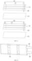
FIG. 3 is a schematic structural diagram of a first connected structure, a second connected structure, a first separator, and a second separator before winding of the flexible battery shown inFIG. 1 ; -
FIG. 4 is a schematic structural diagram of the first connected structure, the second connected structure, the first separator, and the second separator shown inFIG. 3 after winding; -
FIG. 5 is a schematic structural diagram of the flexible battery shown inFIG. 1 from another perspective; -
FIG. 6 is a schematic structural diagram of a flexible battery according to another embodiment of this application; and -
FIG. 7 is a schematic structural diagram of a flexible battery according to another embodiment of this application. - For ease of understanding this application, the following further describes this application in detail with reference to the accompanying drawings and specific embodiments. It should be noted that when an element is described as being "fixed to" another element, the element may be directly on the another element, or there may be one or more elements between the elements. When an element is described as being "connected to" another element, the element may be directly connected to the another element, or there may be one or more elements between the elements. The terms "vertical", "horizontal", "left", "right", "inside", "outside", and similar expressions used in this specification are merely for description purposes.
- Unless otherwise defined, all technical and scientific terms used in this specification shall have the same meanings as commonly understood by persons skilled in the art to which this application belongs. The terms used in the specification of this application are merely intended to describe specific embodiments rather than to constitute any limitation on this application. The term "and/or" used herein includes any and all combinations of one or more associated items that are listed.
- In addition, technical features involved in different embodiments of this application that are described below may be combined as long as they do not conflict with each other.
- Referring to
FIG. 1 and FIG. 2 , an embodiment of this application provides aflexible battery 100 includingcathode plates 10,anode plates 20, a cathodeelectrical connector 30, an anodeelectrical connector 40, andseparators 50. There are a plurality ofcathode plates 10, a plurality ofanode plates 20, and a plurality ofseparators 50. Each of thecathode plates 10 corresponds to one of theanode plates 20, and each of theseparators 50 is disposed between onecorresponding cathode plate 10 and onecorresponding anode plate 20. The plurality ofcathode plates 10 are welded to the cathodeelectrical connector 30, and the plurality ofanode plates 20 are welded to the anodeelectrical connector 40. The plurality ofcathode plates 10, the plurality ofanode plates 20, and the plurality ofseparators 50 are wound on the cathodeelectrical connector 30 and the anodeelectrical connector 40 to form a plurality ofcell units 101 andspine portions 102 connecting adjacent two of thecell units 101. - Referring to
FIG. 3 , thecathode plate 10 is a strip sheet structure, and thecathode plate 10 includes a current collector and a cathode material applied on the current collector, where the current collector of thecathode plate 10 may be an aluminum foil, and the cathode material may be lithium cobaltate, lithium iron phosphate, a ternary material, or the like. Any surface of thecathode plate 10 is divided into a firstuncoated foil region 11, a seconduncoated foil region 12, and afirst coating region 13 according to preset positions. The firstuncoated foil region 11 and the seconduncoated foil region 12 are respectively disposed at two ends of thecathode plate 10 in a length direction of thecathode plate 10, and thefirst coating region 13 is disposed between the firstuncoated foil region 11 and the seconduncoated foil region 12. The plurality ofcathode plates 10 are spaced apart sequentially. The cathodeelectrical connector 30 is welded to the firstuncoated foil regions 11 of the plurality ofcathode plates 10 to form a first connected structure A1. The cathodeelectrical connector 30 and the plurality ofcathode plates 10 may be connected by laser welding, ultrasonic welding, or the like. - The
anode plate 20 is similar to thecathode plate 10 in structure. Theanode plate 20 is a strip sheet structure, and theanode plate 20 includes a current collector and an anode material applied on the current collector, where the current collector of theanode plate 20 may be a copper foil, and the anode material may be graphite, silicon, or the like. Any surface of theanode plate 20 is divided into a thirduncoated foil region 21, a fourthuncoated foil region 22, and asecond coating region 23 according to preset positions. The thirduncoated foil region 21 and the fourthuncoated foil region 22 are respectively disposed at two ends of theanode plate 20 in a length direction of theanode plate 20, and thesecond coating region 23 is disposed between the thirduncoated foil region 21 and the fourthuncoated foil region 22. The plurality ofanode plates 20 are spaced apart sequentially. The anodeelectrical connector 40 is welded to the thirduncoated foil regions 21 of the plurality ofanode plates 20 to form a second connected structure A2. The anodeelectrical connector 40 and the plurality ofanode plates 20 may be connected by laser welding, ultrasonic welding, or the like. - The cathode
electrical connector 30 is made of a metal material. The cathodeelectrical connector 30 is a strip structure or a wire structure. For example, the cathodeelectrical connector 30 may be an aluminum metal strip, a copper wire, or the like. The cathodeelectrical connector 30 extends along an arrangement direction of the plurality ofcathode plates 10. An end of the cathodeelectrical connector 30 extends out of the plurality ofcathode plates 10. The end of the cathodeelectrical connector 30 extending out of the plurality ofcathode plates 10 serves as a positive tab of theflexible battery 100, and a joint between the positive tab and thecathode plate 10 is provided with a tab adhesive (not shown in the figure). - The anode
electrical connector 40 is made of a metal material. The anodeelectrical connector 40 may be a strip structure or a wire structure. For example, the anodeelectrical connector 40 may be a nickel metal strip, an aluminum wire, or the like. The anodeelectrical connector 40 extends along an arrangement direction of the plurality ofanode plates 20. An end of the anodeelectrical connector 40 extends out of the plurality ofanode plates 20. The end of the anodeelectrical connector 40 extending out of the plurality ofanode plates 20 serves as a negative tab of theflexible battery 100, and a joint between the negative tab and theanode plate 20 is provided with a tab adhesive (not shown in the figure). - In some embodiments, after the cathode
electrical connector 30 and the plurality ofcathode plates 10 are welded, a first insulating tape is adhered to each of two surfaces of the cathode electrical connector 30 (not shown in the figure) to form the first connected structure A1; and after the anodeelectrical connector 40 and the plurality ofanode plates 20 are welded, a second insulating tape is adhered to each of two surfaces of the anode electrical connector 40 (not shown in the figure) to form the second connected structure A2, thereby preventing the cathodeelectrical connector 30 and the anodeelectrical connector 40 from puncturing thecathode plates 10, theanode plates 20, and theseparators 50 during winding, and also providing insulation for thespine portions 102. - The
separator 50 is a strip sheet structure made of an insulating material, and theseparator 50 is formed by cutting a complete piece of separator. The complete piece of separator is wound on the cathodeelectrical connector 30 and the anodeelectrical connector 40 and is then cut apart or partially cut apart to form a plurality ofseparators 50. In these embodiments, two complete pieces of separators are provided, which are a first separator A3 and a second separator A4, respectively. - Referring to
FIG. 4 andFIG. 5 , during manufacturing of theflexible battery 100, the first connected structure A1, a complete piece of the first separator A3, the second connected structure A2, and a complete piece of the second separator A4 are first wound using a winding machine to form an integrated structure, and then needless parts of the first separator A3 and second separator A4 are cut apart using a laser cutting process or a mechanism such as a cutting die. - Specifically, the first connected structure A1, the first separator A3, the second connected structure A2, and the second separator A4 are sequentially stacked in a guide groove of the winding machine, each of the
cathode plates 10 corresponds to one of theanode plates 20 in position, and the cathodeelectrical connector 30 corresponds to the anodeelectrical connector 40 in position, thereby guaranteeing parallelism of thecathode plate 10 and theanode plate 20 before winding and during winding; the firstuncoated foil region 11 and the thirduncoated foil region 21 serve as the head of winding, and the first connected structure A1, a complete piece of the first separator A3, the second connected structure A2, and a complete piece of the second separator A4 are wound using the winding machine to form an integrated structure (shown inFIG. 4 ); and portions, located between adjacent two of thecathode plates 10 and between adjacent two of theanode plates 20, of the first separator A3 and the second separator A4 are cut apart, and the first separator A3 and the second separator A4 each form a plurality ofseparators 50, such that the cathodeelectrical connector 30 and the anodeelectrical connector 40 are partially exposed (shown inFIG. 5 ). Acathode plate 10, ananode plate 20, aseparator 50 formed by cutting the first separator A3, and aseparator 50 formed by cutting the second separator A4 are wound to form acell unit 101. Portions, located between adjacent two of thecell units 101, of the cathodeelectrical connector 30 and the anodeelectrical connector 40form spine portions 102. - A distance is provided between adjacent two of the
cell units 101, so as to ensure that theseparators 50 formed by cutting apart the first separator A3 and the second separator A4 do not shrink into thecell units 101. The distance is set based on thickness of the battery and a required bending angle of the battery. The bending angle of the battery is typically not greater than 90 degrees, and the distance is typically not less than the thickness of the battery. The thickness of the battery is thickness of thecell unit 101, and the bending angle of the battery is an included angle between adjacent two of thecell units 101. - Referring to
FIG. 6 and FIG. 7 , in some embodiments, thecell units 101 are set to be bent, thereby improving flexibility of joints of the battery, and reducing a tensile stress from the cathodeelectrical connector 30 and the anodeelectrical connector 40 to thecell units 101. Thecell units 101 can be bent using a mold pressing process, so that two ends of acell unit 101 connected to thespine portions 102 are both bent relative to a central portion of thecell unit 101 to form an arc shape, thereby obtaining a required bending radian. - In some embodiments, the
spine portions 102 are set to be bent, and thespine portions 102 may be of a wavy shape, a sinusoidal shape, a U shape, a zigzag shape, or another specially-structured shape. Thespine portions 102 are bent using a mold-pressing process, and then the plurality ofcell units 101 are integrally bent, thereby reducing a stress of thecell units 101 in a stretching state during integral mold pressing. - In some embodiments, the
flexible battery 100 further includes apackaging film 103, thecell units 101 are accommodated in thepackaging film 103. Thepackaging film 103 may wrap only thecell units 101. Alternatively, thepackaging film 103 may integrally wrap thecell units 101 and thespine portions 102. Still alternatively, thepackaging film 103 separately wraps thecell units 101 and thespine portions 102. This is not limited herein. - The
packaging film 103 may be formed by performing integral packaging with a packaging material, for example, the packaging material is heat-sealed outside thecell unit 101 to form thepackaging film 103. Alternatively, thepackaging film 103 may be formed by performing pit punching on a packaging material, for example, the packaging material is subjected to pit punching according to an overall shape of thecell units 101 and thespine portions 102, and then thecell units 101 and thespine portions 102 are integrally encapsulated in a housing. The packaging material may be an aluminum-plastic film. - The following describes a manufacturing method of
flexible battery 100 with reference to the foregoing accompanying drawings: - a plurality of
cathode plates 10 are spaced apart sequentially, and a cathodeelectrical connector 30 is welded to the plurality ofcathode plates 10 to form a first connected structure A1; - a plurality of
anode plates 20 are spaced apart sequentially, and an anodeelectrical connector 40 is welded to the plurality ofanode plates 20 to form a second connected structure A2; - the first connected structure A1, a first separator A3, the second connected structure A2, and a second separator A4 are sequentially stacked to form a stacked structure;
- the stacked structure is wound using the cathode
electrical connector 30 and the anodeelectrical connector 40 as shafts; - cutting apart portions, located between adjacent two of the anode plates and between adjacent two of the cathode plates, of the first separator A3and the second separator A4, to form a plurality of
cell units 101 andspine portions 102 connecting adjacent two of the cell units; - the
spine portions 102 are bent; - the
cell units 101 are bent; and - the
cell units 101 are packaged in apackaging film 103. - Specifically, the cathode electrical connector 30 and the first uncoated foil regions 11 of the plurality of cathode plates 10 are laser-welded or ultrasonically welded, and then a first insulating tape is adhered to each of two surfaces of the cathode electrical connector 30 to form the first connected structure A1; the anode electrical connector 40 and the third uncoated foil regions 21 of the plurality of anode plates 20 are laser-welded or ultrasonically welded, and then a second insulating tape is adhered to each of two surfaces of the anode electrical connector 40 to form the second connected structure A2; the first connected structure A1, the first separator A3, the second connected structure A2, and the second separator A4 are sequentially stacked and then wound using a winding machine to form an integrated structure; the first separator A3, the plurality of first separators A4, located between adjacent two of the anode plates and between adjacent two of the cathode plates are cut apart using a laser cutting process or a mechanism such as a cutting die; the cell units 101 are mold-pressed into a wavy shape, a sinusoidal shape, a U shape, a zigzag shape, or any other shape; the cell units 101 are bent into an arc shape using a mold pressing process so as to obtain a required bending radian; and a packaging material is formed by heat sealing or pit punching using a die and externally packages the cell units 101.
- In some embodiments, the
cathode plates 10 and theanode plates 20 are already in a required strip structure before coating and therefore need no cutting for winding, thereby avoiding generation of burrs and lumps, reducing safety risks in production, and improving utilization of electrode plates. In addition, the first separator A3 and the second separator A4 are complete pieces of separators disposed between the plurality ofcathode plates 10 and the plurality ofanode plates 20, so that the plurality ofcathode plates 10 and the plurality ofanode plates 20 are integrally wound and molded, improving the production efficiency. Moreover, an end of the cathodeelectrical connector 30 protruding from thecathode plate 10 can serve as a positive tab, and an end of the anodeelectrical connector 40 protruding from theanode plate 20 can serve as a negative tab. Therefore, there is no need to weld tabs additionally, achieving a simpler manufacturing process. - In conclusion, it should be noted that the foregoing embodiments are merely intended to describe the technical solutions of this application, and are not intended to limit this application. Under the idea of this application, the foregoing embodiments or the technical features in different embodiments can also be combined, the steps can be implemented in any order, and there are many other changes in different aspects of this application as described above, which, for the sake of brevity, are not provided in detail. Although this application is described in detail with reference to the foregoing embodiments, persons of ordinary skill in the art should understand that modifications can be made to the technical solutions described in the foregoing embodiments, or equivalent substitutions can be made to some technical features therein, and these modifications or substitutions do not make the essence of the corresponding technical solutions depart from the scope of the technical solutions of some embodiments of this application.
Claims (16)
- A flexible battery, comprising:a plurality of cathode plates;a cathode electrical connector welded to the plurality of cathode plates;a plurality of anode plates, each of the anode plates corresponding to one of the cathode plates;an anode electrical connector welded to the plurality of anode plates; anda plurality of separators, each of the separators being disposed between one corresponding anode plate and one corresponding cathode plate; whereinthe plurality of cathode plates, the plurality of anode plates, and the plurality of separators are wound on the cathode electrical connector and the anode electrical connector to form a plurality of cell units and spine portions connecting adjacent two of the cell units.
- The flexible battery according to claim 1, wherein the cell units are bent, and/or the spine portions are bent.
- The flexible battery according to claim 2, wherein the spine portions are of any one of a wavy shape, a sinusoidal shape, a U shape, or a zigzag shape.
- The flexible battery according to claim 1, wherein a distance is provided between adjacent two of the cell units.
- The flexible battery according to claim 1, wherein the cathode plate comprises a first uncoated foil region, a second uncoated foil region, and a first coating region, the first coating region being located between the first uncoated foil region and the second uncoated foil region;the cathode electrical connector is welded to the first uncoated foil regions of the plurality of cathode plates;the anode plate comprises a third uncoated foil region, a fourth uncoated foil region, and a second coating region, the second coating region being located between the third uncoated foil region and the fourth uncoated foil region; andthe anode electrical connector is welded to the third uncoated foil regions of the plurality of anode plates.
- The flexible battery according to any one of claims 1 to 5, wherein the flexible battery further comprises a packaging film, the cell unit being accommodated in the packaging film.
- The flexible battery according to any one of claims 1 to 5, wherein the cathode electrical connector is provided with a first insulating tape on a surface, and the anode electrical connector is provided with a second insulating tape on a surface.
- A manufacturing method of flexible battery, wherein the method comprising:sequentially spacing apart a plurality of cathode plates;welding a cathode electrical connector to the plurality of cathode plates to form a first connected structure;sequentially spacing apart a plurality of anode plates;welding an anode electrical connector to the plurality of anode plates to form a second connected structure;sequentially stacking the first connected structure, a first separator, the second connected structure, and a second separator to form a stacked structure;winding the stacked structure around a shaft acted by the cathode electrical connector and the anode electrical connector; andcutting apart portions, located between adjacent two of the anode plates and between adjacent two of the cathode plates, of the first separator and the second separator, to form a plurality of cell units and spine portions connecting adjacent two of the cell units.
- The manufacturing method of flexible battery according to claim 8, wherein the method further comprises:
bending the cell units. - The manufacturing method of flexible battery according to claim 8 or 9, wherein the method comprises:
bending the spine portions. - The manufacturing method of flexible battery according to claim 10, wherein the step of bending the spine portions further comprises:
bending the spine portions into any one of a wavy shape, a sinusoidal shape, a U shape, or a zigzag shape. - The manufacturing method of flexible battery according to claim 8, wherein the method further comprises:
packaging the cell units in a packaging film. - The manufacturing method of flexible battery according to claim 8, wherein the cathode plate comprises a first uncoated foil region, a second uncoated foil region, and a first coating region, the first coating region being located between the first uncoated foil region and the second uncoated foil region;the step of welding a cathode electrical connector to the plurality of cathode plates to form a first connected structure further comprises: welding the cathode electrical connector to the first uncoated foil regions of the plurality of cathode plates to form the first connected structure;the anode plate comprises a third uncoated foil region, a fourth uncoated foil region, and a second coating region, the second coating region being located between the third uncoated foil region and the fourth uncoated foil region; andthe step of welding an anode electrical connector to the plurality of anode plates to form a second connected structure further comprises: welding the anode electrical connector to the third uncoated foil regions of the plurality of anode plates to form the second connected structure.
- The manufacturing method of flexible battery according to claim 8 or claim 13, wherein the plurality of cathode plates and the cathode electrical connector are laser-welded or ultrasonically welded; and
the plurality of anode plates and the anode electrical connector are laser-welded or ultrasonically welded. - The manufacturing method of flexible battery according to claim 8, wherein the step of cutting apart portions, located between adjacent two of the anode plates, of the first separator and the second separator further comprises:
cutting apart the portions, located between adjacent two of the anode plates, of the first separator and the second separator by using a laser cutting or die cutting process. - The manufacturing method of flexible battery according to claim 8, wherein the method further comprises:adhering a first insulating tape to each of two surfaces of the cathode electrical connector; andadhering a second insulating tape to each of two surfaces of the anode electrical connector.
Applications Claiming Priority (1)
| Application Number | Priority Date | Filing Date | Title |
|---|---|---|---|
| PCT/CN2021/078706 WO2022183374A1 (en) | 2021-03-02 | 2021-03-02 | Flexible battery and method for manufacturing same |
Publications (2)
| Publication Number | Publication Date |
|---|---|
| EP4300642A1 true EP4300642A1 (en) | 2024-01-03 |
| EP4300642A4 EP4300642A4 (en) | 2025-01-01 |
Family
ID=82025744
Family Applications (1)
| Application Number | Title | Priority Date | Filing Date |
|---|---|---|---|
| EP21928465.0A Pending EP4300642A4 (en) | 2021-03-02 | 2021-03-02 | Flexible battery and method for manufacturing same |
Country Status (3)
| Country | Link |
|---|---|
| EP (1) | EP4300642A4 (en) |
| CN (1) | CN114667636B (en) |
| WO (1) | WO2022183374A1 (en) |
Families Citing this family (1)
| Publication number | Priority date | Publication date | Assignee | Title |
|---|---|---|---|---|
| CN114256500B (en) * | 2021-12-01 | 2024-03-15 | 中国电子科技南湖研究院 | Strip-shaped flexible solid-state battery capable of being cut |
Family Cites Families (12)
| Publication number | Priority date | Publication date | Assignee | Title |
|---|---|---|---|---|
| CN103401024A (en) * | 2013-08-21 | 2013-11-20 | 广州丰江电池新技术股份有限公司 | Arc battery cell, arc single cell, arc cell combination structure and manufacturing method |
| CN105355838A (en) * | 2015-12-03 | 2016-02-24 | 辉能(天津)科技发展有限公司 | Comb-shaped flexible electrode and battery employing comb-shaped flexible electrode |
| KR102278443B1 (en) * | 2016-08-11 | 2021-07-16 | 삼성에스디아이 주식회사 | Rechargeable battery |
| JP7016503B2 (en) * | 2016-09-28 | 2022-02-07 | 株式会社 東北テクノアーチ | Secondary battery |
| WO2018099168A1 (en) * | 2016-12-02 | 2018-06-07 | 东莞新能源科技有限公司 | Cathode plate, anode plate, and battery cell |
| WO2019173826A1 (en) * | 2018-03-09 | 2019-09-12 | The Trustees Of Columbia University In The City Of New York | High-energy-density deformable batteries |
| CN108933222B (en) * | 2018-07-09 | 2019-05-28 | 东莞塔菲尔新能源科技有限公司 | Preparation method of multi-tab secondary lithium ion battery |
| CN209312934U (en) * | 2018-12-25 | 2019-08-27 | 湖北金泉新材料有限责任公司 | A laminated lithium-ion battery |
| CN109560321A (en) * | 2018-12-26 | 2019-04-02 | 蜂巢能源科技有限公司 | Battery core, the manufacturing method of lithium battery and lithium battery of lithium battery |
| CN111180785B (en) * | 2020-02-10 | 2021-03-02 | 廖湘标 | Manufacturing method of flexible battery |
| CN112072162B (en) * | 2020-10-15 | 2024-12-20 | 东莞市创明电池技术有限公司 | Parallel winding core structure of cylindrical batteries and its manufacturing process |
| CN112133953B (en) * | 2020-10-23 | 2023-07-04 | 京东方科技集团股份有限公司 | Flexible battery and flexible display device |
-
2021
- 2021-03-02 WO PCT/CN2021/078706 patent/WO2022183374A1/en not_active Ceased
- 2021-03-02 EP EP21928465.0A patent/EP4300642A4/en active Pending
- 2021-03-02 CN CN202180006353.0A patent/CN114667636B/en active Active
Also Published As
| Publication number | Publication date |
|---|---|
| CN114667636B (en) | 2024-06-14 |
| EP4300642A4 (en) | 2025-01-01 |
| WO2022183374A1 (en) | 2022-09-09 |
| CN114667636A (en) | 2022-06-24 |
Similar Documents
| Publication | Publication Date | Title |
|---|---|---|
| JP7778824B2 (en) | Electrode assembly, molding method thereof, and manufacturing system, secondary battery, battery module, and device | |
| EP3800718B1 (en) | Secondary battery, device, and manufacturing method for secondary battery | |
| CN217239523U (en) | Battery, current collector applied to battery, battery pack comprising current collector and automobile | |
| US20250025957A1 (en) | Electrode Having Improved Electrode Tab Welding Characteristics and Secondary Battery Comprising the Same | |
| KR20210103340A (en) | Secondary battery improved collecting structure | |
| EP2500972B1 (en) | Lithium secondary battery having multi-directional lead-tab structure | |
| KR102303827B1 (en) | Complex electrode assembly including a plurality of electrode assemblies and electrochemical device comprising the complex electrode assembly | |
| CN113366682B (en) | Electrochemical devices and electronic devices | |
| KR102499324B1 (en) | Rolling Device for Secondary Battery | |
| EP3972044A1 (en) | Secondary battery and terminal for secondary battery and manufacturing method thereof | |
| JP6045286B2 (en) | Cylindrical energy storage device | |
| EP3907819B1 (en) | Secondary battery | |
| JP2004071301A (en) | Method for manufacturing storage device case | |
| CN103891024A (en) | Cell provided with spiral electrode, and method for manufacturing same | |
| US10673028B2 (en) | Electrochemical element | |
| WO2017010046A1 (en) | Wound type battery | |
| CN108808113B (en) | Secondary battery and collector terminal | |
| CN115428253B (en) | Electrode for power storage device, power storage device and secondary battery | |
| JP2024545333A (en) | Electrode terminal fixing structure, battery including same, battery pack, and automobile | |
| JP7515205B6 (en) | Enclosure material, method of forming a pattern on the enclosure material, and method of producing a battery including the enclosure material | |
| KR20200058173A (en) | Secondary battery | |
| CN108808011A (en) | Secondary cell and current-collecting terminals | |
| CN114667636B (en) | A flexible battery and a manufacturing method thereof | |
| KR100277638B1 (en) | Electrode assembly manufacturing method and electrode assembly and battery using the electrode assembly | |
| CN112886152B (en) | Battery cell, battery and electronic equipment |
Legal Events
| Date | Code | Title | Description |
|---|---|---|---|
| STAA | Information on the status of an ep patent application or granted ep patent |
Free format text: STATUS: THE INTERNATIONAL PUBLICATION HAS BEEN MADE |
|
| PUAI | Public reference made under article 153(3) epc to a published international application that has entered the european phase |
Free format text: ORIGINAL CODE: 0009012 |
|
| STAA | Information on the status of an ep patent application or granted ep patent |
Free format text: STATUS: REQUEST FOR EXAMINATION WAS MADE |
|
| 17P | Request for examination filed |
Effective date: 20230927 |
|
| AK | Designated contracting states |
Kind code of ref document: A1 Designated state(s): AL AT BE BG CH CY CZ DE DK EE ES FI FR GB GR HR HU IE IS IT LI LT LU LV MC MK MT NL NO PL PT RO RS SE SI SK SM TR |
|
| DAV | Request for validation of the european patent (deleted) | ||
| DAX | Request for extension of the european patent (deleted) | ||
| A4 | Supplementary search report drawn up and despatched |
Effective date: 20241127 |
|
| RIC1 | Information provided on ipc code assigned before grant |
Ipc: H01M 50/516 20210101ALI20241122BHEP Ipc: H01M 10/0587 20100101ALI20241122BHEP Ipc: H01M 10/0583 20100101ALI20241122BHEP Ipc: H01M 50/557 20210101ALI20241122BHEP Ipc: H01M 50/502 20210101ALI20241122BHEP Ipc: H01M 50/211 20210101ALI20241122BHEP Ipc: H01M 50/136 20210101ALI20241122BHEP Ipc: H01M 50/105 20210101ALI20241122BHEP Ipc: H01M 10/058 20100101ALI20241122BHEP Ipc: H01M 10/04 20060101AFI20241122BHEP |