EP4300614A2 - All-solid-state secondary battery and method of preparing the same - Google Patents
All-solid-state secondary battery and method of preparing the same Download PDFInfo
- Publication number
- EP4300614A2 EP4300614A2 EP23178652.6A EP23178652A EP4300614A2 EP 4300614 A2 EP4300614 A2 EP 4300614A2 EP 23178652 A EP23178652 A EP 23178652A EP 4300614 A2 EP4300614 A2 EP 4300614A2
- Authority
- EP
- European Patent Office
- Prior art keywords
- active material
- anode active
- material layer
- solid
- anode
- Prior art date
- Legal status (The legal status is an assumption and is not a legal conclusion. Google has not performed a legal analysis and makes no representation as to the accuracy of the status listed.)
- Pending
Links
- 238000000034 method Methods 0.000 title claims description 41
- 239000006183 anode active material Substances 0.000 claims abstract description 468
- 239000007784 solid electrolyte Substances 0.000 claims abstract description 181
- 229910052751 metal Inorganic materials 0.000 claims abstract description 96
- 239000002184 metal Substances 0.000 claims abstract description 96
- 229910052744 lithium Inorganic materials 0.000 claims abstract description 88
- WHXSMMKQMYFTQS-UHFFFAOYSA-N Lithium Chemical compound [Li] WHXSMMKQMYFTQS-UHFFFAOYSA-N 0.000 claims abstract description 73
- 239000006182 cathode active material Substances 0.000 claims abstract description 59
- OKTJSMMVPCPJKN-UHFFFAOYSA-N Carbon Chemical compound [C] OKTJSMMVPCPJKN-UHFFFAOYSA-N 0.000 claims abstract description 40
- 229910052799 carbon Inorganic materials 0.000 claims abstract description 32
- 229910008015 Li-M Inorganic materials 0.000 claims abstract description 28
- 229910052752 metalloid Inorganic materials 0.000 claims abstract description 20
- 150000002738 metalloids Chemical class 0.000 claims abstract description 20
- 229910000733 Li alloy Inorganic materials 0.000 claims abstract description 16
- 239000001989 lithium alloy Substances 0.000 claims abstract description 16
- 229910001416 lithium ion Inorganic materials 0.000 claims description 69
- 239000002131 composite material Substances 0.000 claims description 68
- 239000002245 particle Substances 0.000 claims description 63
- HBBGRARXTFLTSG-UHFFFAOYSA-N Lithium ion Chemical compound [Li+] HBBGRARXTFLTSG-UHFFFAOYSA-N 0.000 claims description 61
- 239000011148 porous material Substances 0.000 claims description 53
- 239000010408 film Substances 0.000 claims description 51
- 230000009467 reduction Effects 0.000 claims description 41
- 229910001092 metal group alloy Inorganic materials 0.000 claims description 38
- -1 In2Te3 Inorganic materials 0.000 claims description 33
- 238000004544 sputter deposition Methods 0.000 claims description 30
- 239000011701 zinc Substances 0.000 claims description 25
- UCKMPCXJQFINFW-UHFFFAOYSA-N Sulphide Chemical compound [S-2] UCKMPCXJQFINFW-UHFFFAOYSA-N 0.000 claims description 24
- 239000011135 tin Substances 0.000 claims description 24
- 229910052782 aluminium Inorganic materials 0.000 claims description 22
- 239000010936 titanium Substances 0.000 claims description 22
- 229910005900 GeTe Inorganic materials 0.000 claims description 20
- XEEYBQQBJWHFJM-UHFFFAOYSA-N Iron Chemical compound [Fe] XEEYBQQBJWHFJM-UHFFFAOYSA-N 0.000 claims description 17
- PXHVJJICTQNCMI-UHFFFAOYSA-N Nickel Chemical compound [Ni] PXHVJJICTQNCMI-UHFFFAOYSA-N 0.000 claims description 17
- 238000010306 acid treatment Methods 0.000 claims description 17
- 229910052732 germanium Inorganic materials 0.000 claims description 17
- KDLHZDBZIXYQEI-UHFFFAOYSA-N Palladium Chemical compound [Pd] KDLHZDBZIXYQEI-UHFFFAOYSA-N 0.000 claims description 16
- 229910052710 silicon Inorganic materials 0.000 claims description 16
- BASFCYQUMIYNBI-UHFFFAOYSA-N platinum Chemical compound [Pt] BASFCYQUMIYNBI-UHFFFAOYSA-N 0.000 claims description 14
- 229910052718 tin Inorganic materials 0.000 claims description 14
- 229910052719 titanium Inorganic materials 0.000 claims description 14
- 229910052725 zinc Inorganic materials 0.000 claims description 14
- 229910003481 amorphous carbon Inorganic materials 0.000 claims description 13
- 229910052804 chromium Inorganic materials 0.000 claims description 13
- 239000011651 chromium Substances 0.000 claims description 13
- 239000010949 copper Substances 0.000 claims description 13
- 229910052742 iron Inorganic materials 0.000 claims description 13
- MCMNRKCIXSYSNV-UHFFFAOYSA-N Zirconium dioxide Chemical compound O=[Zr]=O MCMNRKCIXSYSNV-UHFFFAOYSA-N 0.000 claims description 12
- 229910052759 nickel Inorganic materials 0.000 claims description 12
- 229910052709 silver Inorganic materials 0.000 claims description 12
- 229910052726 zirconium Inorganic materials 0.000 claims description 12
- 229910052797 bismuth Inorganic materials 0.000 claims description 11
- 229910052763 palladium Inorganic materials 0.000 claims description 11
- 229910052802 copper Inorganic materials 0.000 claims description 10
- 229910052733 gallium Inorganic materials 0.000 claims description 10
- 229910052749 magnesium Inorganic materials 0.000 claims description 10
- 239000011777 magnesium Substances 0.000 claims description 10
- 229910052697 platinum Inorganic materials 0.000 claims description 10
- 229910001215 Te alloy Inorganic materials 0.000 claims description 9
- 229910052737 gold Inorganic materials 0.000 claims description 9
- 239000010931 gold Substances 0.000 claims description 9
- 229910052738 indium Inorganic materials 0.000 claims description 9
- 229910052758 niobium Inorganic materials 0.000 claims description 9
- 239000010955 niobium Substances 0.000 claims description 9
- RYGMFSIKBFXOCR-UHFFFAOYSA-N Copper Chemical compound [Cu] RYGMFSIKBFXOCR-UHFFFAOYSA-N 0.000 claims description 8
- XAGFODPZIPBFFR-UHFFFAOYSA-N aluminium Chemical compound [Al] XAGFODPZIPBFFR-UHFFFAOYSA-N 0.000 claims description 8
- 229910052787 antimony Inorganic materials 0.000 claims description 8
- 150000002500 ions Chemical class 0.000 claims description 8
- 239000007787 solid Substances 0.000 claims description 8
- 229910052684 Cerium Inorganic materials 0.000 claims description 7
- 150000002642 lithium compounds Chemical class 0.000 claims description 7
- 150000002739 metals Chemical class 0.000 claims description 7
- 229910052720 vanadium Inorganic materials 0.000 claims description 7
- BQCADISMDOOEFD-UHFFFAOYSA-N Silver Chemical compound [Ag] BQCADISMDOOEFD-UHFFFAOYSA-N 0.000 claims description 6
- JCXGWMGPZLAOME-UHFFFAOYSA-N bismuth atom Chemical compound [Bi] JCXGWMGPZLAOME-UHFFFAOYSA-N 0.000 claims description 6
- 229910052796 boron Inorganic materials 0.000 claims description 6
- 239000004332 silver Substances 0.000 claims description 6
- 229910009176 Li2S—P2 Inorganic materials 0.000 claims description 5
- FYYHWMGAXLPEAU-UHFFFAOYSA-N Magnesium Chemical compound [Mg] FYYHWMGAXLPEAU-UHFFFAOYSA-N 0.000 claims description 5
- XUIMIQQOPSSXEZ-UHFFFAOYSA-N Silicon Chemical compound [Si] XUIMIQQOPSSXEZ-UHFFFAOYSA-N 0.000 claims description 5
- ATJFFYVFTNAWJD-UHFFFAOYSA-N Tin Chemical compound [Sn] ATJFFYVFTNAWJD-UHFFFAOYSA-N 0.000 claims description 5
- RTAQQCXQSZGOHL-UHFFFAOYSA-N Titanium Chemical compound [Ti] RTAQQCXQSZGOHL-UHFFFAOYSA-N 0.000 claims description 5
- HCHKCACWOHOZIP-UHFFFAOYSA-N Zinc Chemical compound [Zn] HCHKCACWOHOZIP-UHFFFAOYSA-N 0.000 claims description 5
- QCWXUUIWCKQGHC-UHFFFAOYSA-N Zirconium Chemical compound [Zr] QCWXUUIWCKQGHC-UHFFFAOYSA-N 0.000 claims description 5
- 229910007667 ZnOx Inorganic materials 0.000 claims description 5
- 229910052792 caesium Inorganic materials 0.000 claims description 5
- 239000011575 calcium Substances 0.000 claims description 5
- GNPVGFCGXDBREM-UHFFFAOYSA-N germanium atom Chemical compound [Ge] GNPVGFCGXDBREM-UHFFFAOYSA-N 0.000 claims description 5
- 229910052698 phosphorus Inorganic materials 0.000 claims description 5
- 239000010703 silicon Substances 0.000 claims description 5
- 239000011734 sodium Substances 0.000 claims description 5
- 229910052712 strontium Inorganic materials 0.000 claims description 5
- 229910052714 tellurium Inorganic materials 0.000 claims description 5
- 239000010409 thin film Substances 0.000 claims description 5
- GYHNNYVSQQEPJS-UHFFFAOYSA-N Gallium Chemical compound [Ga] GYHNNYVSQQEPJS-UHFFFAOYSA-N 0.000 claims description 4
- 229910009297 Li2S-P2S5 Inorganic materials 0.000 claims description 4
- 229910009228 Li2S—P2S5 Inorganic materials 0.000 claims description 4
- WMFOQBRAJBCJND-UHFFFAOYSA-M Lithium hydroxide Chemical compound [Li+].[OH-] WMFOQBRAJBCJND-UHFFFAOYSA-M 0.000 claims description 4
- VYPSYNLAJGMNEJ-UHFFFAOYSA-N Silicium dioxide Chemical compound O=[Si]=O VYPSYNLAJGMNEJ-UHFFFAOYSA-N 0.000 claims description 4
- GWEVSGVZZGPLCZ-UHFFFAOYSA-N Titan oxide Chemical compound O=[Ti]=O GWEVSGVZZGPLCZ-UHFFFAOYSA-N 0.000 claims description 4
- WATWJIUSRGPENY-UHFFFAOYSA-N antimony atom Chemical compound [Sb] WATWJIUSRGPENY-UHFFFAOYSA-N 0.000 claims description 4
- 229910052785 arsenic Inorganic materials 0.000 claims description 4
- 229910052791 calcium Inorganic materials 0.000 claims description 4
- PCHJSUWPFVWCPO-UHFFFAOYSA-N gold Chemical compound [Au] PCHJSUWPFVWCPO-UHFFFAOYSA-N 0.000 claims description 4
- APFVFJFRJDLVQX-UHFFFAOYSA-N indium atom Chemical compound [In] APFVFJFRJDLVQX-UHFFFAOYSA-N 0.000 claims description 4
- GUCVJGMIXFAOAE-UHFFFAOYSA-N niobium atom Chemical compound [Nb] GUCVJGMIXFAOAE-UHFFFAOYSA-N 0.000 claims description 4
- 229910052814 silicon oxide Inorganic materials 0.000 claims description 4
- 229910052708 sodium Inorganic materials 0.000 claims description 4
- XOLBLPGZBRYERU-UHFFFAOYSA-N tin dioxide Chemical compound O=[Sn]=O XOLBLPGZBRYERU-UHFFFAOYSA-N 0.000 claims description 4
- 229910052721 tungsten Inorganic materials 0.000 claims description 4
- VYZAMTAEIAYCRO-UHFFFAOYSA-N Chromium Chemical compound [Cr] VYZAMTAEIAYCRO-UHFFFAOYSA-N 0.000 claims description 3
- DGAQECJNVWCQMB-PUAWFVPOSA-M Ilexoside XXIX Chemical compound C[C@@H]1CC[C@@]2(CC[C@@]3(C(=CC[C@H]4[C@]3(CC[C@@H]5[C@@]4(CC[C@@H](C5(C)C)OS(=O)(=O)[O-])C)C)[C@@H]2[C@]1(C)O)C)C(=O)O[C@H]6[C@@H]([C@H]([C@@H]([C@H](O6)CO)O)O)O.[Na+] DGAQECJNVWCQMB-PUAWFVPOSA-M 0.000 claims description 3
- FUJCRWPEOMXPAD-UHFFFAOYSA-N Li2O Inorganic materials [Li+].[Li+].[O-2] FUJCRWPEOMXPAD-UHFFFAOYSA-N 0.000 claims description 3
- 229910011103 Li7−xPS6−xClx Inorganic materials 0.000 claims description 3
- 229910010092 LiAlO2 Inorganic materials 0.000 claims description 3
- 229910020351 Pb1-xLaxZr1-yTiyO3 Inorganic materials 0.000 claims description 3
- 229910020345 Pb1−xLaxZr1−yTiyO3 Inorganic materials 0.000 claims description 3
- 238000010348 incorporation Methods 0.000 claims description 3
- 229910052746 lanthanum Inorganic materials 0.000 claims description 3
- 229910052700 potassium Inorganic materials 0.000 claims description 3
- 238000005507 spraying Methods 0.000 claims description 3
- 229910052715 tantalum Inorganic materials 0.000 claims description 3
- 229910052727 yttrium Inorganic materials 0.000 claims description 3
- OYPRJOBELJOOCE-UHFFFAOYSA-N Calcium Chemical compound [Ca] OYPRJOBELJOOCE-UHFFFAOYSA-N 0.000 claims description 2
- 229910007977 Li1+x+y(AlaGa1−a)x(TibGe1−b)2−xSiyP3−yO12 Inorganic materials 0.000 claims description 2
- 229910008026 Li1+x+yAlxTi2-xSiyP3-yO12 Inorganic materials 0.000 claims description 2
- 229910008043 Li1+x+yAlxTi2−xSiyP3-yO12 Inorganic materials 0.000 claims description 2
- 229910006188 Li1+x+yAlxTi2−xSiyP3−yO12 Inorganic materials 0.000 claims description 2
- 229910008550 Li2O—Al2O3—SiO2—P2O5—TiO2—GeO2 Inorganic materials 0.000 claims description 2
- 229910009294 Li2S-B2S3 Inorganic materials 0.000 claims description 2
- 229910009292 Li2S-GeS2 Inorganic materials 0.000 claims description 2
- 229910009298 Li2S-P2S5-Li2O Inorganic materials 0.000 claims description 2
- 229910009311 Li2S-SiS2 Inorganic materials 0.000 claims description 2
- 229910009324 Li2S-SiS2-Li3PO4 Inorganic materials 0.000 claims description 2
- 229910009320 Li2S-SiS2-LiBr Inorganic materials 0.000 claims description 2
- 229910009318 Li2S-SiS2-LiI Inorganic materials 0.000 claims description 2
- 229910009328 Li2S-SiS2—Li3PO4 Inorganic materials 0.000 claims description 2
- 229910009346 Li2S—B2S3 Inorganic materials 0.000 claims description 2
- 229910009351 Li2S—GeS2 Inorganic materials 0.000 claims description 2
- 229910009219 Li2S—P2S5—Li2O Inorganic materials 0.000 claims description 2
- 229910009433 Li2S—SiS2 Inorganic materials 0.000 claims description 2
- 229910007295 Li2S—SiS2—Li3PO4 Inorganic materials 0.000 claims description 2
- 229910007291 Li2S—SiS2—LiBr Inorganic materials 0.000 claims description 2
- 229910007289 Li2S—SiS2—LiI Inorganic materials 0.000 claims description 2
- 229910007306 Li2S—SiS2—P2S5LiI Inorganic materials 0.000 claims description 2
- 229910012107 Li3+xLa3M2O12 Inorganic materials 0.000 claims description 2
- 229910018413 LixAlyTiz(PO4)3 Inorganic materials 0.000 claims description 2
- 229910016983 LixLayTiO3 Inorganic materials 0.000 claims description 2
- 229910014694 LixTiy(PO4)3 Inorganic materials 0.000 claims description 2
- KKCBUQHMOMHUOY-UHFFFAOYSA-N Na2O Inorganic materials [O-2].[Na+].[Na+] KKCBUQHMOMHUOY-UHFFFAOYSA-N 0.000 claims description 2
- 229910020213 PB(Mg3Nb2/3)O3-PbTiO3 Inorganic materials 0.000 claims description 2
- 229910020210 Pb(Mg3Nb2/3)O3—PbTiO3 Inorganic materials 0.000 claims description 2
- 229910020291 Pb(ZraTi1−a)O3 Inorganic materials 0.000 claims description 2
- ZLMJMSJWJFRBEC-UHFFFAOYSA-N Potassium Chemical compound [K] ZLMJMSJWJFRBEC-UHFFFAOYSA-N 0.000 claims description 2
- 229910002370 SrTiO3 Inorganic materials 0.000 claims description 2
- PNEYBMLMFCGWSK-UHFFFAOYSA-N aluminium oxide Inorganic materials [O-2].[O-2].[O-2].[Al+3].[Al+3] PNEYBMLMFCGWSK-UHFFFAOYSA-N 0.000 claims description 2
- 229910052788 barium Inorganic materials 0.000 claims description 2
- DSAJWYNOEDNPEQ-UHFFFAOYSA-N barium atom Chemical compound [Ba] DSAJWYNOEDNPEQ-UHFFFAOYSA-N 0.000 claims description 2
- TVFDJXOCXUVLDH-UHFFFAOYSA-N caesium atom Chemical compound [Cs] TVFDJXOCXUVLDH-UHFFFAOYSA-N 0.000 claims description 2
- CETPSERCERDGAM-UHFFFAOYSA-N ceric oxide Chemical compound O=[Ce]=O CETPSERCERDGAM-UHFFFAOYSA-N 0.000 claims description 2
- 229910000422 cerium(IV) oxide Inorganic materials 0.000 claims description 2
- 229910017052 cobalt Inorganic materials 0.000 claims description 2
- 239000010941 cobalt Substances 0.000 claims description 2
- GUTLYIVDDKVIGB-UHFFFAOYSA-N cobalt atom Chemical compound [Co] GUTLYIVDDKVIGB-UHFFFAOYSA-N 0.000 claims description 2
- 229910052681 coesite Inorganic materials 0.000 claims description 2
- 229910052593 corundum Inorganic materials 0.000 claims description 2
- 229910052906 cristobalite Inorganic materials 0.000 claims description 2
- XUCJHNOBJLKZNU-UHFFFAOYSA-M dilithium;hydroxide Chemical compound [Li+].[Li+].[OH-] XUCJHNOBJLKZNU-UHFFFAOYSA-M 0.000 claims description 2
- 238000001548 drop coating Methods 0.000 claims description 2
- 229910052735 hafnium Inorganic materials 0.000 claims description 2
- VBJZVLUMGGDVMO-UHFFFAOYSA-N hafnium atom Chemical compound [Hf] VBJZVLUMGGDVMO-UHFFFAOYSA-N 0.000 claims description 2
- CJNBYAVZURUTKZ-UHFFFAOYSA-N hafnium(IV) oxide Inorganic materials O=[Hf]=O CJNBYAVZURUTKZ-UHFFFAOYSA-N 0.000 claims description 2
- 229910052736 halogen Inorganic materials 0.000 claims description 2
- 125000005843 halogen group Chemical group 0.000 claims description 2
- 238000001764 infiltration Methods 0.000 claims description 2
- 230000008595 infiltration Effects 0.000 claims description 2
- FZLIPJUXYLNCLC-UHFFFAOYSA-N lanthanum atom Chemical compound [La] FZLIPJUXYLNCLC-UHFFFAOYSA-N 0.000 claims description 2
- XGZVUEUWXADBQD-UHFFFAOYSA-L lithium carbonate Chemical compound [Li+].[Li+].[O-]C([O-])=O XGZVUEUWXADBQD-UHFFFAOYSA-L 0.000 claims description 2
- 229910052808 lithium carbonate Inorganic materials 0.000 claims description 2
- 229910001386 lithium phosphate Inorganic materials 0.000 claims description 2
- 239000011591 potassium Substances 0.000 claims description 2
- 239000000377 silicon dioxide Substances 0.000 claims description 2
- 229910052682 stishovite Inorganic materials 0.000 claims description 2
- CIOAGBVUUVVLOB-UHFFFAOYSA-N strontium atom Chemical compound [Sr] CIOAGBVUUVVLOB-UHFFFAOYSA-N 0.000 claims description 2
- GUVRBAGPIYLISA-UHFFFAOYSA-N tantalum atom Chemical compound [Ta] GUVRBAGPIYLISA-UHFFFAOYSA-N 0.000 claims description 2
- 229910052905 tridymite Inorganic materials 0.000 claims description 2
- TWQULNDIKKJZPH-UHFFFAOYSA-K trilithium;phosphate Chemical compound [Li+].[Li+].[Li+].[O-]P([O-])([O-])=O TWQULNDIKKJZPH-UHFFFAOYSA-K 0.000 claims description 2
- LEONUFNNVUYDNQ-UHFFFAOYSA-N vanadium atom Chemical compound [V] LEONUFNNVUYDNQ-UHFFFAOYSA-N 0.000 claims description 2
- 229910001845 yogo sapphire Inorganic materials 0.000 claims description 2
- VWQVUPCCIRVNHF-UHFFFAOYSA-N yttrium atom Chemical compound [Y] VWQVUPCCIRVNHF-UHFFFAOYSA-N 0.000 claims description 2
- 229910018110 Se—Te Inorganic materials 0.000 claims 2
- 229910005642 SnTe Inorganic materials 0.000 claims 2
- GWXLDORMOJMVQZ-UHFFFAOYSA-N cerium Chemical compound [Ce] GWXLDORMOJMVQZ-UHFFFAOYSA-N 0.000 claims 2
- 229910002688 Ag2Te Inorganic materials 0.000 claims 1
- 229910002899 Bi2Te3 Inorganic materials 0.000 claims 1
- 229910016339 Bi—Sb—Te Inorganic materials 0.000 claims 1
- ZOXJGFHDIHLPTG-UHFFFAOYSA-N Boron Chemical compound [B] ZOXJGFHDIHLPTG-UHFFFAOYSA-N 0.000 claims 1
- 229910004613 CdTe Inorganic materials 0.000 claims 1
- 229910005866 GeSe Inorganic materials 0.000 claims 1
- 229910009316 Li2S-SiS2-LiCl Inorganic materials 0.000 claims 1
- 229910007288 Li2S—SiS2—LiCl Inorganic materials 0.000 claims 1
- 229910016021 MoTe2 Inorganic materials 0.000 claims 1
- 229910020046 NbTe2 Inorganic materials 0.000 claims 1
- 229910017629 Sb2Te3 Inorganic materials 0.000 claims 1
- 229910004411 SrTe Inorganic materials 0.000 claims 1
- RQNWIZPPADIBDY-UHFFFAOYSA-N arsenic atom Chemical compound [As] RQNWIZPPADIBDY-UHFFFAOYSA-N 0.000 claims 1
- 229910002113 barium titanate Inorganic materials 0.000 claims 1
- WPBNNNQJVZRUHP-UHFFFAOYSA-L manganese(2+);methyl n-[[2-(methoxycarbonylcarbamothioylamino)phenyl]carbamothioyl]carbamate;n-[2-(sulfidocarbothioylamino)ethyl]carbamodithioate Chemical compound [Mn+2].[S-]C(=S)NCCNC([S-])=S.COC(=O)NC(=S)NC1=CC=CC=C1NC(=S)NC(=O)OC WPBNNNQJVZRUHP-UHFFFAOYSA-L 0.000 claims 1
- 238000004528 spin coating Methods 0.000 claims 1
- PORWMNRCUJJQNO-UHFFFAOYSA-N tellurium atom Chemical compound [Te] PORWMNRCUJJQNO-UHFFFAOYSA-N 0.000 claims 1
- WFKWXMTUELFFGS-UHFFFAOYSA-N tungsten Chemical compound [W] WFKWXMTUELFFGS-UHFFFAOYSA-N 0.000 claims 1
- 239000010937 tungsten Substances 0.000 claims 1
- 150000001875 compounds Chemical class 0.000 abstract description 23
- 239000010410 layer Substances 0.000 description 405
- 238000007600 charging Methods 0.000 description 74
- 238000007599 discharging Methods 0.000 description 62
- 230000000052 comparative effect Effects 0.000 description 43
- 238000003825 pressing Methods 0.000 description 43
- 238000006722 reduction reaction Methods 0.000 description 39
- 239000011230 binding agent Substances 0.000 description 38
- 239000000463 material Substances 0.000 description 38
- 239000002002 slurry Substances 0.000 description 36
- 229910002984 Li7La3Zr2O12 Inorganic materials 0.000 description 29
- 238000010438 heat treatment Methods 0.000 description 27
- 229910045601 alloy Inorganic materials 0.000 description 26
- 239000000956 alloy Substances 0.000 description 26
- 239000000203 mixture Substances 0.000 description 23
- 239000011888 foil Substances 0.000 description 21
- 239000012298 atmosphere Substances 0.000 description 17
- 238000003756 stirring Methods 0.000 description 17
- 238000012360 testing method Methods 0.000 description 16
- 238000000576 coating method Methods 0.000 description 15
- 239000008188 pellet Substances 0.000 description 15
- 230000008569 process Effects 0.000 description 14
- 239000011248 coating agent Substances 0.000 description 12
- 238000002156 mixing Methods 0.000 description 12
- 239000000243 solution Substances 0.000 description 12
- XLYOFNOQVPJJNP-UHFFFAOYSA-N water Substances O XLYOFNOQVPJJNP-UHFFFAOYSA-N 0.000 description 12
- 238000005275 alloying Methods 0.000 description 11
- 238000009792 diffusion process Methods 0.000 description 11
- 239000011247 coating layer Substances 0.000 description 10
- 239000007789 gas Substances 0.000 description 10
- 230000002829 reductive effect Effects 0.000 description 10
- 239000006229 carbon black Substances 0.000 description 9
- 238000000354 decomposition reaction Methods 0.000 description 9
- 239000011244 liquid electrolyte Substances 0.000 description 9
- 235000002639 sodium chloride Nutrition 0.000 description 9
- FAPWRFPIFSIZLT-UHFFFAOYSA-M Sodium chloride Chemical compound [Na+].[Cl-] FAPWRFPIFSIZLT-UHFFFAOYSA-M 0.000 description 8
- 239000011149 active material Substances 0.000 description 8
- 230000015572 biosynthetic process Effects 0.000 description 8
- 238000006243 chemical reaction Methods 0.000 description 8
- 238000011156 evaluation Methods 0.000 description 8
- 238000010884 ion-beam technique Methods 0.000 description 8
- 229910052748 manganese Inorganic materials 0.000 description 8
- 239000011572 manganese Substances 0.000 description 8
- 238000001556 precipitation Methods 0.000 description 8
- 238000002360 preparation method Methods 0.000 description 8
- 229910003069 TeO2 Inorganic materials 0.000 description 7
- 239000006258 conductive agent Substances 0.000 description 7
- 239000008151 electrolyte solution Substances 0.000 description 7
- 238000010894 electron beam technology Methods 0.000 description 7
- 239000002608 ionic liquid Substances 0.000 description 7
- 229910021437 lithium-transition metal oxide Inorganic materials 0.000 description 7
- 238000004519 manufacturing process Methods 0.000 description 7
- VNWKTOKETHGBQD-UHFFFAOYSA-N methane Chemical compound C VNWKTOKETHGBQD-UHFFFAOYSA-N 0.000 description 7
- 229910052760 oxygen Inorganic materials 0.000 description 7
- 239000011780 sodium chloride Substances 0.000 description 7
- QVGXLLKOCUKJST-UHFFFAOYSA-N atomic oxygen Chemical compound [O] QVGXLLKOCUKJST-UHFFFAOYSA-N 0.000 description 6
- 239000002134 carbon nanofiber Substances 0.000 description 6
- 238000000151 deposition Methods 0.000 description 6
- 230000008021 deposition Effects 0.000 description 6
- 230000001965 increasing effect Effects 0.000 description 6
- 239000011229 interlayer Substances 0.000 description 6
- 229910003002 lithium salt Inorganic materials 0.000 description 6
- 159000000002 lithium salts Chemical class 0.000 description 6
- 238000005259 measurement Methods 0.000 description 6
- 230000001590 oxidative effect Effects 0.000 description 6
- 239000001301 oxygen Substances 0.000 description 6
- 229920001343 polytetrafluoroethylene Polymers 0.000 description 6
- 238000001552 radio frequency sputter deposition Methods 0.000 description 6
- 229910001216 Li2S Inorganic materials 0.000 description 5
- 210000004027 cell Anatomy 0.000 description 5
- 238000003701 mechanical milling Methods 0.000 description 5
- 239000002243 precursor Substances 0.000 description 5
- 239000000758 substrate Substances 0.000 description 5
- 239000011800 void material Substances 0.000 description 5
- LFQSCWFLJHTTHZ-UHFFFAOYSA-N Ethanol Chemical compound CCO LFQSCWFLJHTTHZ-UHFFFAOYSA-N 0.000 description 4
- VEXZGXHMUGYJMC-UHFFFAOYSA-N Hydrochloric acid Chemical compound Cl VEXZGXHMUGYJMC-UHFFFAOYSA-N 0.000 description 4
- 229910002995 LiNi0.8Co0.15Al0.05O2 Inorganic materials 0.000 description 4
- 239000003929 acidic solution Substances 0.000 description 4
- 238000004458 analytical method Methods 0.000 description 4
- 239000003795 chemical substances by application Substances 0.000 description 4
- VDVLPSWVDYJFRW-UHFFFAOYSA-N lithium;bis(fluorosulfonyl)azanide Chemical compound [Li+].FS(=O)(=O)[N-]S(F)(=O)=O VDVLPSWVDYJFRW-UHFFFAOYSA-N 0.000 description 4
- 239000011259 mixed solution Substances 0.000 description 4
- 238000010298 pulverizing process Methods 0.000 description 4
- 239000000523 sample Substances 0.000 description 4
- LAJZODKXOMJMPK-UHFFFAOYSA-N tellurium dioxide Chemical compound O=[Te]=O LAJZODKXOMJMPK-UHFFFAOYSA-N 0.000 description 4
- 229910008575 LiaNi1-b-cCobBc Inorganic materials 0.000 description 3
- 229910008620 LiaNi1-b-cMnbBc Inorganic materials 0.000 description 3
- 229910014972 LiaNi1—b−cMnbBc Inorganic materials 0.000 description 3
- 229910014955 LiaNi1−b−cCobBc Inorganic materials 0.000 description 3
- OKKJLVBELUTLKV-UHFFFAOYSA-N Methanol Chemical compound OC OKKJLVBELUTLKV-UHFFFAOYSA-N 0.000 description 3
- 239000004698 Polyethylene Substances 0.000 description 3
- 239000004809 Teflon Substances 0.000 description 3
- 229920006362 Teflon® Polymers 0.000 description 3
- 239000006230 acetylene black Substances 0.000 description 3
- 150000001450 anions Chemical class 0.000 description 3
- 239000012300 argon atmosphere Substances 0.000 description 3
- 238000000498 ball milling Methods 0.000 description 3
- 150000001768 cations Chemical class 0.000 description 3
- 230000008859 change Effects 0.000 description 3
- 239000011889 copper foil Substances 0.000 description 3
- 238000007598 dipping method Methods 0.000 description 3
- 239000002270 dispersing agent Substances 0.000 description 3
- 239000000945 filler Substances 0.000 description 3
- 239000012212 insulator Substances 0.000 description 3
- 239000003273 ketjen black Substances 0.000 description 3
- 238000007578 melt-quenching technique Methods 0.000 description 3
- 239000007773 negative electrode material Substances 0.000 description 3
- 229920003229 poly(methyl methacrylate) Polymers 0.000 description 3
- 229920000573 polyethylene Polymers 0.000 description 3
- 239000004926 polymethyl methacrylate Substances 0.000 description 3
- 229920002981 polyvinylidene fluoride Polymers 0.000 description 3
- 238000010791 quenching Methods 0.000 description 3
- 230000000171 quenching effect Effects 0.000 description 3
- 230000002441 reversible effect Effects 0.000 description 3
- 239000002904 solvent Substances 0.000 description 3
- 239000010935 stainless steel Substances 0.000 description 3
- 229910001220 stainless steel Inorganic materials 0.000 description 3
- 229920003048 styrene butadiene rubber Polymers 0.000 description 3
- 229910052717 sulfur Inorganic materials 0.000 description 3
- BFKJFAAPBSQJPD-UHFFFAOYSA-N tetrafluoroethene Chemical compound FC(F)=C(F)F BFKJFAAPBSQJPD-UHFFFAOYSA-N 0.000 description 3
- QGZKDVFQNNGYKY-UHFFFAOYSA-O Ammonium Chemical compound [NH4+] QGZKDVFQNNGYKY-UHFFFAOYSA-O 0.000 description 2
- XKRFYHLGVUSROY-UHFFFAOYSA-N Argon Chemical compound [Ar] XKRFYHLGVUSROY-UHFFFAOYSA-N 0.000 description 2
- IJGRMHOSHXDMSA-UHFFFAOYSA-N Atomic nitrogen Chemical compound N#N IJGRMHOSHXDMSA-UHFFFAOYSA-N 0.000 description 2
- 229910005143 FSO2 Inorganic materials 0.000 description 2
- 229910000927 Ge alloy Inorganic materials 0.000 description 2
- RAXXELZNTBOGNW-UHFFFAOYSA-O Imidazolium Chemical compound C1=C[NH+]=CN1 RAXXELZNTBOGNW-UHFFFAOYSA-O 0.000 description 2
- UQSXHKLRYXJYBZ-UHFFFAOYSA-N Iron oxide Chemical compound [Fe]=O UQSXHKLRYXJYBZ-UHFFFAOYSA-N 0.000 description 2
- 229910021460 LiaNibCocMndGeO2 Inorganic materials 0.000 description 2
- 229910019142 PO4 Inorganic materials 0.000 description 2
- NQRYJNQNLNOLGT-UHFFFAOYSA-O Piperidinium(1+) Chemical compound C1CC[NH2+]CC1 NQRYJNQNLNOLGT-UHFFFAOYSA-O 0.000 description 2
- 239000002174 Styrene-butadiene Substances 0.000 description 2
- 238000004833 X-ray photoelectron spectroscopy Methods 0.000 description 2
- 239000000654 additive Substances 0.000 description 2
- 238000005054 agglomeration Methods 0.000 description 2
- 230000002776 aggregation Effects 0.000 description 2
- 239000007864 aqueous solution Substances 0.000 description 2
- 239000012752 auxiliary agent Substances 0.000 description 2
- 229910001914 chlorine tetroxide Inorganic materials 0.000 description 2
- 239000004020 conductor Substances 0.000 description 2
- 239000013078 crystal Substances 0.000 description 2
- 238000004090 dissolution Methods 0.000 description 2
- 239000003792 electrolyte Substances 0.000 description 2
- 230000005496 eutectics Effects 0.000 description 2
- 229910052731 fluorine Inorganic materials 0.000 description 2
- 239000006232 furnace black Substances 0.000 description 2
- 229910002804 graphite Inorganic materials 0.000 description 2
- 239000010439 graphite Substances 0.000 description 2
- 230000002706 hydrostatic effect Effects 0.000 description 2
- 238000002847 impedance measurement Methods 0.000 description 2
- 238000001095 inductively coupled plasma mass spectrometry Methods 0.000 description 2
- 230000001678 irradiating effect Effects 0.000 description 2
- 230000000670 limiting effect Effects 0.000 description 2
- KWGKDLIKAYFUFQ-UHFFFAOYSA-M lithium chloride Chemical compound [Li+].[Cl-] KWGKDLIKAYFUFQ-UHFFFAOYSA-M 0.000 description 2
- 229910000625 lithium cobalt oxide Inorganic materials 0.000 description 2
- BFZPBUKRYWOWDV-UHFFFAOYSA-N lithium;oxido(oxo)cobalt Chemical compound [Li+].[O-][Co]=O BFZPBUKRYWOWDV-UHFFFAOYSA-N 0.000 description 2
- 238000002844 melting Methods 0.000 description 2
- 230000008018 melting Effects 0.000 description 2
- 239000012454 non-polar solvent Substances 0.000 description 2
- 239000011368 organic material Substances 0.000 description 2
- 239000003960 organic solvent Substances 0.000 description 2
- VLTRZXGMWDSKGL-UHFFFAOYSA-M perchlorate Chemical compound [O-]Cl(=O)(=O)=O VLTRZXGMWDSKGL-UHFFFAOYSA-M 0.000 description 2
- XYFCBTPGUUZFHI-UHFFFAOYSA-O phosphonium Chemical compound [PH4+] XYFCBTPGUUZFHI-UHFFFAOYSA-O 0.000 description 2
- 229920000642 polymer Polymers 0.000 description 2
- 229920000036 polyvinylpyrrolidone Polymers 0.000 description 2
- 239000001267 polyvinylpyrrolidone Substances 0.000 description 2
- 235000013855 polyvinylpyrrolidone Nutrition 0.000 description 2
- 239000011164 primary particle Substances 0.000 description 2
- 238000004549 pulsed laser deposition Methods 0.000 description 2
- JUJWROOIHBZHMG-UHFFFAOYSA-O pyridinium Chemical compound C1=CC=[NH+]C=C1 JUJWROOIHBZHMG-UHFFFAOYSA-O 0.000 description 2
- 239000000376 reactant Substances 0.000 description 2
- 150000003839 salts Chemical class 0.000 description 2
- 238000001228 spectrum Methods 0.000 description 2
- 239000000126 substance Substances 0.000 description 2
- 238000004627 transmission electron microscopy Methods 0.000 description 2
- 238000001771 vacuum deposition Methods 0.000 description 2
- LZDKZFUFMNSQCJ-UHFFFAOYSA-N 1,2-diethoxyethane Chemical compound CCOCCOCC LZDKZFUFMNSQCJ-UHFFFAOYSA-N 0.000 description 1
- 229910001148 Al-Li alloy Inorganic materials 0.000 description 1
- 229910017048 AsF6 Inorganic materials 0.000 description 1
- 229910001020 Au alloy Inorganic materials 0.000 description 1
- 229920000049 Carbon (fiber) Polymers 0.000 description 1
- 229910001560 Li(CF3SO2)2N Inorganic materials 0.000 description 1
- 229910005140 Li(FSO2)2N Inorganic materials 0.000 description 1
- 229910008266 Li-Ag Inorganic materials 0.000 description 1
- 229910008029 Li-In Inorganic materials 0.000 description 1
- 229910008365 Li-Sn Inorganic materials 0.000 description 1
- 229910008405 Li-Zn Inorganic materials 0.000 description 1
- 229910008920 Li2O—ZrO2 Inorganic materials 0.000 description 1
- 229910009305 Li2S-P2S5-Li2O-LiI Inorganic materials 0.000 description 1
- 229910009322 Li2S-SiS2-LiCI Inorganic materials 0.000 description 1
- 229910009222 Li2S—P2S5—Li2O—LiI Inorganic materials 0.000 description 1
- 229910007281 Li2S—SiS2—B2S3LiI Inorganic materials 0.000 description 1
- 229910010854 Li6PS5Br Inorganic materials 0.000 description 1
- 229910010848 Li6PS5Cl Inorganic materials 0.000 description 1
- 229910001559 LiC4F9SO3 Inorganic materials 0.000 description 1
- 229910000552 LiCF3SO3 Inorganic materials 0.000 description 1
- 229910032387 LiCoO2 Inorganic materials 0.000 description 1
- 229910052493 LiFePO4 Inorganic materials 0.000 description 1
- 229910010878 LiIO2 Inorganic materials 0.000 description 1
- 229910021447 LiN(CxF2x+1SO2)(CyF2y+1SO2) Inorganic materials 0.000 description 1
- 229910013124 LiNiVO4 Inorganic materials 0.000 description 1
- 229910013410 LiNixCoyAlzO2 Inorganic materials 0.000 description 1
- 229910013467 LiNixCoyMnzO2 Inorganic materials 0.000 description 1
- 229910001290 LiPF6 Inorganic materials 0.000 description 1
- 229910021466 LiQS2 Inorganic materials 0.000 description 1
- 229910012946 LiV2O5 Inorganic materials 0.000 description 1
- 229910021462 LiaCoGbO2 Inorganic materials 0.000 description 1
- 229910021464 LiaMn2GbO4 Inorganic materials 0.000 description 1
- 229910021461 LiaNiGbO2 Inorganic materials 0.000 description 1
- 229910021459 LiaNibEcGdO2 Inorganic materials 0.000 description 1
- 229910000572 Lithium Nickel Cobalt Manganese Oxide (NCM) Inorganic materials 0.000 description 1
- 229910008445 Li—Ag Inorganic materials 0.000 description 1
- 229910006670 Li—In Inorganic materials 0.000 description 1
- 229910006759 Li—Sn Inorganic materials 0.000 description 1
- 229910007049 Li—Zn Inorganic materials 0.000 description 1
- 229910004598 P2S5 (Li2S:P2S5 Inorganic materials 0.000 description 1
- 239000002202 Polyethylene glycol Substances 0.000 description 1
- 239000004372 Polyvinyl alcohol Substances 0.000 description 1
- 229910000676 Si alloy Inorganic materials 0.000 description 1
- 238000000026 X-ray photoelectron spectrum Methods 0.000 description 1
- QTHKJEYUQSLYTH-UHFFFAOYSA-N [Co]=O.[Ni].[Li] Chemical compound [Co]=O.[Ni].[Li] QTHKJEYUQSLYTH-UHFFFAOYSA-N 0.000 description 1
- XHCLAFWTIXFWPH-UHFFFAOYSA-N [O-2].[O-2].[O-2].[O-2].[O-2].[V+5].[V+5] Chemical compound [O-2].[O-2].[O-2].[O-2].[O-2].[V+5].[V+5] XHCLAFWTIXFWPH-UHFFFAOYSA-N 0.000 description 1
- 239000002253 acid Substances 0.000 description 1
- 230000002411 adverse Effects 0.000 description 1
- 239000000443 aerosol Substances 0.000 description 1
- 229910000905 alloy phase Inorganic materials 0.000 description 1
- NDPGDHBNXZOBJS-UHFFFAOYSA-N aluminum lithium cobalt(2+) nickel(2+) oxygen(2-) Chemical compound [Li+].[O--].[O--].[O--].[O--].[Al+3].[Co++].[Ni++] NDPGDHBNXZOBJS-UHFFFAOYSA-N 0.000 description 1
- 229910052786 argon Inorganic materials 0.000 description 1
- 125000004429 atom Chemical group 0.000 description 1
- 230000004888 barrier function Effects 0.000 description 1
- 229910002056 binary alloy Inorganic materials 0.000 description 1
- 230000005540 biological transmission Effects 0.000 description 1
- RXKLBLXXQQRGJH-UHFFFAOYSA-N bis(fluorosulfonyl)azanide 1-methyl-1-propylpyrrolidin-1-ium Chemical compound CCC[N+]1(C)CCCC1.FS(=O)(=O)[N-]S(F)(=O)=O RXKLBLXXQQRGJH-UHFFFAOYSA-N 0.000 description 1
- INDFXCHYORWHLQ-UHFFFAOYSA-N bis(trifluoromethylsulfonyl)azanide;1-butyl-3-methylimidazol-3-ium Chemical compound CCCCN1C=C[N+](C)=C1.FC(F)(F)S(=O)(=O)[N-]S(=O)(=O)C(F)(F)F INDFXCHYORWHLQ-UHFFFAOYSA-N 0.000 description 1
- LRESCJAINPKJTO-UHFFFAOYSA-N bis(trifluoromethylsulfonyl)azanide;1-ethyl-3-methylimidazol-3-ium Chemical compound CCN1C=C[N+](C)=C1.FC(F)(F)S(=O)(=O)[N-]S(=O)(=O)C(F)(F)F LRESCJAINPKJTO-UHFFFAOYSA-N 0.000 description 1
- DKNRELLLVOYIIB-UHFFFAOYSA-N bis(trifluoromethylsulfonyl)azanide;1-methyl-1-propylpyrrolidin-1-ium Chemical compound CCC[N+]1(C)CCCC1.FC(F)(F)S(=O)(=O)[N-]S(=O)(=O)C(F)(F)F DKNRELLLVOYIIB-UHFFFAOYSA-N 0.000 description 1
- 239000004917 carbon fiber Substances 0.000 description 1
- NKCVNYJQLIWBHK-UHFFFAOYSA-N carbonodiperoxoic acid Chemical compound OOC(=O)OO NKCVNYJQLIWBHK-UHFFFAOYSA-N 0.000 description 1
- 230000015556 catabolic process Effects 0.000 description 1
- ZMIGMASIKSOYAM-UHFFFAOYSA-N cerium Chemical compound [Ce][Ce][Ce][Ce][Ce][Ce][Ce][Ce][Ce][Ce][Ce][Ce][Ce][Ce][Ce][Ce][Ce][Ce][Ce][Ce][Ce][Ce][Ce][Ce][Ce][Ce][Ce][Ce][Ce][Ce][Ce][Ce][Ce][Ce][Ce][Ce][Ce][Ce] ZMIGMASIKSOYAM-UHFFFAOYSA-N 0.000 description 1
- 238000004891 communication Methods 0.000 description 1
- 239000000470 constituent Substances 0.000 description 1
- OMZSGWSJDCOLKM-UHFFFAOYSA-N copper(II) sulfide Chemical compound [S-2].[Cu+2] OMZSGWSJDCOLKM-UHFFFAOYSA-N 0.000 description 1
- 238000005336 cracking Methods 0.000 description 1
- 230000003247 decreasing effect Effects 0.000 description 1
- 238000006731 degradation reaction Methods 0.000 description 1
- 230000000593 degrading effect Effects 0.000 description 1
- 210000001787 dendrite Anatomy 0.000 description 1
- 238000011161 development Methods 0.000 description 1
- 238000010586 diagram Methods 0.000 description 1
- QHGJSLXSVXVKHZ-UHFFFAOYSA-N dilithium;dioxido(dioxo)manganese Chemical compound [Li+].[Li+].[O-][Mn]([O-])(=O)=O QHGJSLXSVXVKHZ-UHFFFAOYSA-N 0.000 description 1
- 238000009826 distribution Methods 0.000 description 1
- 238000001035 drying Methods 0.000 description 1
- 230000000694 effects Effects 0.000 description 1
- 239000007772 electrode material Substances 0.000 description 1
- 238000005430 electron energy loss spectroscopy Methods 0.000 description 1
- 238000010828 elution Methods 0.000 description 1
- 238000002474 experimental method Methods 0.000 description 1
- 238000004880 explosion Methods 0.000 description 1
- 238000000605 extraction Methods 0.000 description 1
- 230000014509 gene expression Effects 0.000 description 1
- 230000009477 glass transition Effects 0.000 description 1
- 229910021389 graphene Inorganic materials 0.000 description 1
- XLYOFNOQVPJJNP-UHFFFAOYSA-M hydroxide Chemical compound [OH-] XLYOFNOQVPJJNP-UHFFFAOYSA-M 0.000 description 1
- 150000003949 imides Chemical class 0.000 description 1
- 230000006698 induction Effects 0.000 description 1
- 230000001939 inductive effect Effects 0.000 description 1
- 238000007737 ion beam deposition Methods 0.000 description 1
- 238000007733 ion plating Methods 0.000 description 1
- 229910052745 lead Inorganic materials 0.000 description 1
- 239000007788 liquid Substances 0.000 description 1
- 229910001547 lithium hexafluoroantimonate(V) Inorganic materials 0.000 description 1
- 229910001540 lithium hexafluoroarsenate(V) Inorganic materials 0.000 description 1
- GELKBWJHTRAYNV-UHFFFAOYSA-K lithium iron phosphate Chemical compound [Li+].[Fe+2].[O-]P([O-])([O-])=O GELKBWJHTRAYNV-UHFFFAOYSA-K 0.000 description 1
- 229910001947 lithium oxide Inorganic materials 0.000 description 1
- MHCFAGZWMAWTNR-UHFFFAOYSA-M lithium perchlorate Chemical compound [Li+].[O-]Cl(=O)(=O)=O MHCFAGZWMAWTNR-UHFFFAOYSA-M 0.000 description 1
- 229910001486 lithium perchlorate Inorganic materials 0.000 description 1
- GLNWILHOFOBOFD-UHFFFAOYSA-N lithium sulfide Chemical compound [Li+].[Li+].[S-2] GLNWILHOFOBOFD-UHFFFAOYSA-N 0.000 description 1
- 229910001537 lithium tetrachloroaluminate Inorganic materials 0.000 description 1
- 229910001496 lithium tetrafluoroborate Inorganic materials 0.000 description 1
- URIIGZKXFBNRAU-UHFFFAOYSA-N lithium;oxonickel Chemical compound [Li].[Ni]=O URIIGZKXFBNRAU-UHFFFAOYSA-N 0.000 description 1
- 230000007774 longterm Effects 0.000 description 1
- 238000001755 magnetron sputter deposition Methods 0.000 description 1
- 230000014759 maintenance of location Effects 0.000 description 1
- 239000011159 matrix material Substances 0.000 description 1
- 238000013508 migration Methods 0.000 description 1
- 230000005012 migration Effects 0.000 description 1
- 238000003801 milling Methods 0.000 description 1
- 238000001451 molecular beam epitaxy Methods 0.000 description 1
- 229910052750 molybdenum Inorganic materials 0.000 description 1
- 238000000465 moulding Methods 0.000 description 1
- 229910052757 nitrogen Inorganic materials 0.000 description 1
- 238000013021 overheating Methods 0.000 description 1
- 238000001420 photoelectron spectroscopy Methods 0.000 description 1
- 230000000704 physical effect Effects 0.000 description 1
- 238000007747 plating Methods 0.000 description 1
- 239000002798 polar solvent Substances 0.000 description 1
- 229920002239 polyacrylonitrile Polymers 0.000 description 1
- 229920001223 polyethylene glycol Polymers 0.000 description 1
- 229920002451 polyvinyl alcohol Polymers 0.000 description 1
- 239000000843 powder Substances 0.000 description 1
- 239000011241 protective layer Substances 0.000 description 1
- 229910052761 rare earth metal Inorganic materials 0.000 description 1
- 230000035484 reaction time Effects 0.000 description 1
- 238000005546 reactive sputtering Methods 0.000 description 1
- 238000001945 resonance Rayleigh scattering spectroscopy Methods 0.000 description 1
- 230000004044 response Effects 0.000 description 1
- 229910052706 scandium Inorganic materials 0.000 description 1
- 238000007650 screen-printing Methods 0.000 description 1
- 229910052711 selenium Inorganic materials 0.000 description 1
- 239000004065 semiconductor Substances 0.000 description 1
- 238000007086 side reaction Methods 0.000 description 1
- 239000010944 silver (metal) Substances 0.000 description 1
- 238000005245 sintering Methods 0.000 description 1
- 239000006104 solid solution Substances 0.000 description 1
- 239000007921 spray Substances 0.000 description 1
- 239000007858 starting material Substances 0.000 description 1
- WWNBZGLDODTKEM-UHFFFAOYSA-N sulfanylidenenickel Chemical compound [Ni]=S WWNBZGLDODTKEM-UHFFFAOYSA-N 0.000 description 1
- 230000001629 suppression Effects 0.000 description 1
- 229910052723 transition metal Inorganic materials 0.000 description 1
- 229910000314 transition metal oxide Inorganic materials 0.000 description 1
- 150000003624 transition metals Chemical class 0.000 description 1
- ZIBGPFATKBEMQZ-UHFFFAOYSA-N triethylene glycol Chemical compound OCCOCCOCCO ZIBGPFATKBEMQZ-UHFFFAOYSA-N 0.000 description 1
- 229910001935 vanadium oxide Inorganic materials 0.000 description 1
- 238000007740 vapor deposition Methods 0.000 description 1
- 229920005609 vinylidenefluoride/hexafluoropropylene copolymer Polymers 0.000 description 1
Images


Classifications
-
- H—ELECTRICITY
- H01—ELECTRIC ELEMENTS
- H01M—PROCESSES OR MEANS, e.g. BATTERIES, FOR THE DIRECT CONVERSION OF CHEMICAL ENERGY INTO ELECTRICAL ENERGY
- H01M4/00—Electrodes
- H01M4/02—Electrodes composed of, or comprising, active material
- H01M4/04—Processes of manufacture in general
- H01M4/0402—Methods of deposition of the material
- H01M4/0407—Methods of deposition of the material by coating on an electrolyte layer
-
- H—ELECTRICITY
- H01—ELECTRIC ELEMENTS
- H01M—PROCESSES OR MEANS, e.g. BATTERIES, FOR THE DIRECT CONVERSION OF CHEMICAL ENERGY INTO ELECTRICAL ENERGY
- H01M4/00—Electrodes
- H01M4/02—Electrodes composed of, or comprising, active material
- H01M4/36—Selection of substances as active materials, active masses, active liquids
- H01M4/362—Composites
- H01M4/366—Composites as layered products
-
- H—ELECTRICITY
- H01—ELECTRIC ELEMENTS
- H01M—PROCESSES OR MEANS, e.g. BATTERIES, FOR THE DIRECT CONVERSION OF CHEMICAL ENERGY INTO ELECTRICAL ENERGY
- H01M10/00—Secondary cells; Manufacture thereof
- H01M10/05—Accumulators with non-aqueous electrolyte
- H01M10/052—Li-accumulators
- H01M10/0525—Rocking-chair batteries, i.e. batteries with lithium insertion or intercalation in both electrodes; Lithium-ion batteries
-
- H—ELECTRICITY
- H01—ELECTRIC ELEMENTS
- H01M—PROCESSES OR MEANS, e.g. BATTERIES, FOR THE DIRECT CONVERSION OF CHEMICAL ENERGY INTO ELECTRICAL ENERGY
- H01M10/00—Secondary cells; Manufacture thereof
- H01M10/05—Accumulators with non-aqueous electrolyte
- H01M10/056—Accumulators with non-aqueous electrolyte characterised by the materials used as electrolytes, e.g. mixed inorganic/organic electrolytes
- H01M10/0561—Accumulators with non-aqueous electrolyte characterised by the materials used as electrolytes, e.g. mixed inorganic/organic electrolytes the electrolyte being constituted of inorganic materials only
- H01M10/0562—Solid materials
-
- H—ELECTRICITY
- H01—ELECTRIC ELEMENTS
- H01M—PROCESSES OR MEANS, e.g. BATTERIES, FOR THE DIRECT CONVERSION OF CHEMICAL ENERGY INTO ELECTRICAL ENERGY
- H01M4/00—Electrodes
- H01M4/02—Electrodes composed of, or comprising, active material
- H01M4/04—Processes of manufacture in general
- H01M4/0402—Methods of deposition of the material
- H01M4/0404—Methods of deposition of the material by coating on electrode collectors
-
- H—ELECTRICITY
- H01—ELECTRIC ELEMENTS
- H01M—PROCESSES OR MEANS, e.g. BATTERIES, FOR THE DIRECT CONVERSION OF CHEMICAL ENERGY INTO ELECTRICAL ENERGY
- H01M4/00—Electrodes
- H01M4/02—Electrodes composed of, or comprising, active material
- H01M4/04—Processes of manufacture in general
- H01M4/0402—Methods of deposition of the material
- H01M4/0416—Methods of deposition of the material involving impregnation with a solution, dispersion, paste or dry powder
-
- H—ELECTRICITY
- H01—ELECTRIC ELEMENTS
- H01M—PROCESSES OR MEANS, e.g. BATTERIES, FOR THE DIRECT CONVERSION OF CHEMICAL ENERGY INTO ELECTRICAL ENERGY
- H01M4/00—Electrodes
- H01M4/02—Electrodes composed of, or comprising, active material
- H01M4/13—Electrodes for accumulators with non-aqueous electrolyte, e.g. for lithium-accumulators; Processes of manufacture thereof
- H01M4/131—Electrodes based on mixed oxides or hydroxides, or on mixtures of oxides or hydroxides, e.g. LiCoOx
-
- H—ELECTRICITY
- H01—ELECTRIC ELEMENTS
- H01M—PROCESSES OR MEANS, e.g. BATTERIES, FOR THE DIRECT CONVERSION OF CHEMICAL ENERGY INTO ELECTRICAL ENERGY
- H01M4/00—Electrodes
- H01M4/02—Electrodes composed of, or comprising, active material
- H01M4/13—Electrodes for accumulators with non-aqueous electrolyte, e.g. for lithium-accumulators; Processes of manufacture thereof
- H01M4/133—Electrodes based on carbonaceous material, e.g. graphite-intercalation compounds or CFx
-
- H—ELECTRICITY
- H01—ELECTRIC ELEMENTS
- H01M—PROCESSES OR MEANS, e.g. BATTERIES, FOR THE DIRECT CONVERSION OF CHEMICAL ENERGY INTO ELECTRICAL ENERGY
- H01M4/00—Electrodes
- H01M4/02—Electrodes composed of, or comprising, active material
- H01M4/13—Electrodes for accumulators with non-aqueous electrolyte, e.g. for lithium-accumulators; Processes of manufacture thereof
- H01M4/139—Processes of manufacture
- H01M4/1391—Processes of manufacture of electrodes based on mixed oxides or hydroxides, or on mixtures of oxides or hydroxides, e.g. LiCoOx
-
- H—ELECTRICITY
- H01—ELECTRIC ELEMENTS
- H01M—PROCESSES OR MEANS, e.g. BATTERIES, FOR THE DIRECT CONVERSION OF CHEMICAL ENERGY INTO ELECTRICAL ENERGY
- H01M4/00—Electrodes
- H01M4/02—Electrodes composed of, or comprising, active material
- H01M4/13—Electrodes for accumulators with non-aqueous electrolyte, e.g. for lithium-accumulators; Processes of manufacture thereof
- H01M4/139—Processes of manufacture
- H01M4/1393—Processes of manufacture of electrodes based on carbonaceous material, e.g. graphite-intercalation compounds or CFx
-
- H—ELECTRICITY
- H01—ELECTRIC ELEMENTS
- H01M—PROCESSES OR MEANS, e.g. BATTERIES, FOR THE DIRECT CONVERSION OF CHEMICAL ENERGY INTO ELECTRICAL ENERGY
- H01M4/00—Electrodes
- H01M4/02—Electrodes composed of, or comprising, active material
- H01M4/36—Selection of substances as active materials, active masses, active liquids
- H01M4/362—Composites
- H01M4/364—Composites as mixtures
-
- H—ELECTRICITY
- H01—ELECTRIC ELEMENTS
- H01M—PROCESSES OR MEANS, e.g. BATTERIES, FOR THE DIRECT CONVERSION OF CHEMICAL ENERGY INTO ELECTRICAL ENERGY
- H01M4/00—Electrodes
- H01M4/02—Electrodes composed of, or comprising, active material
- H01M4/36—Selection of substances as active materials, active masses, active liquids
- H01M4/38—Selection of substances as active materials, active masses, active liquids of elements or alloys
- H01M4/40—Alloys based on alkali metals
- H01M4/405—Alloys based on lithium
-
- H—ELECTRICITY
- H01—ELECTRIC ELEMENTS
- H01M—PROCESSES OR MEANS, e.g. BATTERIES, FOR THE DIRECT CONVERSION OF CHEMICAL ENERGY INTO ELECTRICAL ENERGY
- H01M4/00—Electrodes
- H01M4/02—Electrodes composed of, or comprising, active material
- H01M4/36—Selection of substances as active materials, active masses, active liquids
- H01M4/48—Selection of substances as active materials, active masses, active liquids of inorganic oxides or hydroxides
- H01M4/485—Selection of substances as active materials, active masses, active liquids of inorganic oxides or hydroxides of mixed oxides or hydroxides for inserting or intercalating light metals, e.g. LiTi2O4 or LiTi2OxFy
-
- H—ELECTRICITY
- H01—ELECTRIC ELEMENTS
- H01M—PROCESSES OR MEANS, e.g. BATTERIES, FOR THE DIRECT CONVERSION OF CHEMICAL ENERGY INTO ELECTRICAL ENERGY
- H01M4/00—Electrodes
- H01M4/02—Electrodes composed of, or comprising, active material
- H01M4/36—Selection of substances as active materials, active masses, active liquids
- H01M4/58—Selection of substances as active materials, active masses, active liquids of inorganic compounds other than oxides or hydroxides, e.g. sulfides, selenides, tellurides, halogenides or LiCoFy; of polyanionic structures, e.g. phosphates, silicates or borates
- H01M4/583—Carbonaceous material, e.g. graphite-intercalation compounds or CFx
- H01M4/587—Carbonaceous material, e.g. graphite-intercalation compounds or CFx for inserting or intercalating light metals
-
- H—ELECTRICITY
- H01—ELECTRIC ELEMENTS
- H01M—PROCESSES OR MEANS, e.g. BATTERIES, FOR THE DIRECT CONVERSION OF CHEMICAL ENERGY INTO ELECTRICAL ENERGY
- H01M4/00—Electrodes
- H01M4/02—Electrodes composed of, or comprising, active material
- H01M2004/021—Physical characteristics, e.g. porosity, surface area
-
- H—ELECTRICITY
- H01—ELECTRIC ELEMENTS
- H01M—PROCESSES OR MEANS, e.g. BATTERIES, FOR THE DIRECT CONVERSION OF CHEMICAL ENERGY INTO ELECTRICAL ENERGY
- H01M4/00—Electrodes
- H01M4/02—Electrodes composed of, or comprising, active material
- H01M2004/026—Electrodes composed of, or comprising, active material characterised by the polarity
- H01M2004/027—Negative electrodes
-
- H—ELECTRICITY
- H01—ELECTRIC ELEMENTS
- H01M—PROCESSES OR MEANS, e.g. BATTERIES, FOR THE DIRECT CONVERSION OF CHEMICAL ENERGY INTO ELECTRICAL ENERGY
- H01M2300/00—Electrolytes
- H01M2300/0017—Non-aqueous electrolytes
- H01M2300/002—Inorganic electrolyte
-
- H—ELECTRICITY
- H01—ELECTRIC ELEMENTS
- H01M—PROCESSES OR MEANS, e.g. BATTERIES, FOR THE DIRECT CONVERSION OF CHEMICAL ENERGY INTO ELECTRICAL ENERGY
- H01M2300/00—Electrolytes
- H01M2300/0017—Non-aqueous electrolytes
- H01M2300/0065—Solid electrolytes
- H01M2300/0068—Solid electrolytes inorganic
- H01M2300/008—Halides
-
- Y—GENERAL TAGGING OF NEW TECHNOLOGICAL DEVELOPMENTS; GENERAL TAGGING OF CROSS-SECTIONAL TECHNOLOGIES SPANNING OVER SEVERAL SECTIONS OF THE IPC; TECHNICAL SUBJECTS COVERED BY FORMER USPC CROSS-REFERENCE ART COLLECTIONS [XRACs] AND DIGESTS
- Y02—TECHNOLOGIES OR APPLICATIONS FOR MITIGATION OR ADAPTATION AGAINST CLIMATE CHANGE
- Y02E—REDUCTION OF GREENHOUSE GAS [GHG] EMISSIONS, RELATED TO ENERGY GENERATION, TRANSMISSION OR DISTRIBUTION
- Y02E60/00—Enabling technologies; Technologies with a potential or indirect contribution to GHG emissions mitigation
- Y02E60/10—Energy storage using batteries
Definitions
- the present subject matter relates to an all-solid-state secondary battery and a method of preparing the same.
- lithium-ion batteries are being put to practical use not only in the fields of information-related devices and communication devices, but also in the fields of automobiles.
- safety is considered especially important as it is related to protecting life.
- Lithium-ion batteries currently available on the market use a liquid electrolyte containing a flammable organic solvent, and thus overheating and fire may occur in the case of a short circuit.
- all-solid-state secondary batteries using a solid electrolyte instead of a liquid electrolyte have been proposed.
- All-solid-state batteries do not contain a flammable organic solvent, and thus the possibility of fire or explosion may be greatly reduced even in the case of a short circuit. Therefore, such all-solid-state secondary batteries may significantly increase stability compared to lithium-ion batteries using a liquid electrolyte.
- an electrolyte used is solid, and thus lithium may locally be deposited at an interface between a solid electrolyte layer and an anode.
- the deposited lithium may grow and consequently penetrate a solid electrolyte layer, resulting in a short circuit of the battery.
- the effective interface area between the solid electrolyte layer and the anode becomes smaller than the actual contact area therebetween. Accordingly, as the interfacial resistance increases at the interface between the solid electrolyte layer and the anode, the internal resistance of the battery may increase, thereby degrading the cycle characteristics and capacity of the battery.
- an all-solid-state secondary battery in which a short circuit is prevented during charging and discharging, and cycle characteristics are improved.
- an all-solid-state secondary battery includes:
- a method of preparing the all-solid-state secondary battery includes
- first, second, third etc. may be used herein to describe various elements, components, regions, layers, and/or sections, these elements, components, regions, layers, and/or sections should not be limited by these terms. These terms are only used to distinguish one element, component, region, layer, or section from another element, component, region, layer, or section. Thus, a first element, component, region, layer, or section discussed below could be termed a second element, component, region, layer, or section without departing from the teachings of the present embodiments.
- Exemplary embodiments are described herein with reference to cross section illustrations that are schematic illustrations of idealized embodiments. As such, variations from the shapes of the illustrations as a result, for example, of manufacturing techniques and/or tolerances, are to be expected. Thus, embodiments described herein should not be construed as limited to the particular shapes of regions as illustrated herein but are to include deviations in shapes that result, for example, from manufacturing. For example, a region illustrated or described as flat may, typically, have rough and/or nonlinear features. Moreover, sharp angles that are illustrated may be rounded. Thus, the regions illustrated in the figures are schematic in nature and their shapes are not intended to illustrate the precise shape of a region and are not intended to limit the scope of the present claims.
- an anode structure for an all-solid-state secondary battery according to one or more embodiments, an all-solid-state secondary battery including the same, and a method of preparing the all-solid-state secondary battery will be described in more detail.
- An aspect provides an all-solid-state secondary battery including:
- the first anode active material layer is arranged adjacent to the solid electrolyte, and includes:
- anode including the carbon-containing anode active material in the all-solid-state secondary battery does not have an excellent binding force with a solid electrolyte, thus interfacial stability between the anode and the solid electrolyte may not be sufficient.
- an anode consists of a metal only
- current imbalance may occur due to agglomeration of particles in a process of alloying and dealloying with lithium during charging and discharging cycles, and accordingly, an alloy phase having low lithium diffusion may be formed and some of the high rate characteristics may be degraded.
- a metal diffuses within an electrode during charging and discharging cycles at a high temperature, the lifespan characteristics of an all-solid-state secondary battery may be degraded.
- the all-solid-state secondary battery is provided to solve the above-mentioned problems. Since the first anode active material layer in contact with the solid electrolyte includes the M 1 -M 2 O x composite, the Li-M 1 -M 2 O x composite, or a combination thereof, void formation or volume changes may be suppressed at high current density during charging and discharging cycles, and the all-solid-state secondary battery is controlled to have a pore structure with a large surface area, thereby obtaining an effect of widening a surface diffusion path, and thus a lithium diffusion rate increases in a solution with a pH of 7 or less.
- the movement of lithium ions from the first anode active material layer to the second anode active material layer may be controlled to be fast.
- an adhesion force between the solid electrolyte and the second anode active material layer arranged to be in contact with the anode current collector may be improved.
- the void formation at high current density during charging and discharging cycles may be suppressed, and thus the rate characteristics and the lifespan characteristics may be improved.
- the first metal M 1 may be a material inducing a reversible alloying/dealloying reaction with lithium
- M 2 O x which is an oxide of the second metal M 2
- M 2 O x may serve as a backbone matrix and may have a role in the uniform induction and the suppression of the void formation during charging and discharging cycles.
- the first metal (M 1 ) and the second metals (M 2 ) may each independently refer to an element that maintains a solid state in a solution with a pH of 7 or less, and may each have a lithium ion diffusivity of 1 ⁇ 10 -14 square centimeters per second (cm 2 /sec) or greater at 25°C.
- the term "metal" used herein includes at least one selected metal and metalloid.
- the first metal (M 1 ) and the second metals (M 2 ) may each be a metal that is alloyable with lithium
- the first metal and the second metal, M 1 and M 2 may be identical to (the same as) or different from each other, and may each independently be Si, Sn, Ag, Al, Zn, Ge, Mg, Te, Pb, As, Na, Bi, Ti, B, W, Mn, Fe, Ni, Cu, Cr, Zr, Ce, or a combination thereof.
- the M 1 -M 2 O x composite and the Li-M 1 -M 2 O x composite may each be prepared by coating and treating a metal (e.g., Te, Si, Ge, Sb, or the like) or a metal alloy (e.g., GeTe, or the like).
- a metal e.g., Te, Si, Ge, Sb, or the like
- a metal alloy e.g., GeTe, or the like.
- Component analysis of these composites may be performed by resonance Raman spectroscopy, X-photoelectron spectroscopy (XPS), transmission electron microscopy (TEM), energy dispersed X-ray (EDX) electron energy loss spectroscopy (EELS), inductively coupled plasma-mass spectroscopy (ICP-MS), or the like.
- XPS X-photoelectron spectroscopy
- TEM transmission electron microscopy
- EDX energy dispersed X-ray
- EELS energy loss spectros
- M 1 -M 2 O x composite and the Li-M 1 -M 2 O x composite for example, 0 ⁇ x ⁇ 2.
- the first and second metals M 1 and M 2 may be the same as or different from each other, and the composite may include, for example, Te-TeOx, wherein 0 ⁇ x ⁇ 2; Li a -Te x -Te y O 2 , wherein 0 ⁇ a ⁇ 5, 0 ⁇ x ⁇ 3, and 0 ⁇ y ⁇ 2; Li-Te-TeOx, wherein 0 ⁇ x ⁇ 2; Te-ZnOx; wherein 0 ⁇ x ⁇ 2; Li a -Te x -Zn y O 2 , wherein 0 ⁇ a ⁇ 5, 0 ⁇ x ⁇ 3, and 0 ⁇ y ⁇ 2; or Li-Te-ZnOx, wherein 0 ⁇ x ⁇ 2.
- an amount of M 2 O x may be about 0.05 parts by weight to about 50 parts by weight, based on 100 parts by weight of the total weight of the M 1 -M 2 O x composite.
- the amount of M 2 O x may be about 0.1 parts by weight to about 48 parts by weight, about 1 parts by weight to about 45 parts by weight, or about 5 parts by weight to about 43 parts by weight, based on 100 parts by weight of the total weight of the M 1 -M 2 O x composite.
- the amount of M 2 O x is within the ranges above, a binding force between the solid electrolyte and the anode active material layer may increase, and accordingly, the void formation at high current density during charging and discharging cycles may be suppressed, and the volume changes may be reduced. As a result, the all-solid-state secondary battery having improved rate characteristics and long-lifespan characteristics may be prepared.
- an amount of the lithium may be about 0.01 parts by weight to about 80 parts by weight, based on 100 parts by weight of a total weight of the Li-M 1 -M 2 O x composite
- an amount of M 1 may be about 10 parts by weight to about 70 parts by weight, based on 100 parts by weight of the total weight of the Li-M 1 -M 2 O x composite
- an amount of M 2 O x may be about 0.05 parts by weight to about 50 parts by weight, based on 100 parts by weight of the total weight of the Li-M 1 -M 2 O x composite.
- the binding force between the solid electrolyte and the anode active material layer may increase, and accordingly, the void formation at high current density during charging and discharging cycles may be suppressed, and the volume changes may be reduced. As a result, the all-solid-state secondary battery having improved rate characteristics and long-lifespan characteristics may be prepared.
- a thickness of the first anode active material layer may be about 10 nanometers (nm) to about 500 nm, and the first anode active material layer may include a plurality of pores (i.e., two or more pores).
- a second anode active material may be included in the pores of the first anode active material layer.
- at least one of the plurality of pores may include the second anode active material disposed therein.
- the first anode active material layer may includes a plurality of pores, at least one of the plurality of pores comprises the second anode active material disposed therein, and a porosity of the first anode active material layer is less than the porosity of the first anode active material layer that does not comprise the second anode active material disposed therein, or the first anode active material layer is non-porous by incorporation of the second anode active material.
- the second anode active material included in the second anode active material layer may be provided in at least one of the pores of the first anode active material layer so that porosity of the first anode active material layer may be reduced, or the pores may disappear (i.e., the first anode active material layer may become non-porous by incorporation of the second anode active material in the pores thereof).
- a size of the plurality of pores in the first anode active material layer may be about 3 nm to about 50 nm. In other words, at least one pore of the plurality of pores may have a size of about 3 nm to about 50 nm.
- the metals M 1 and M 2 may be selected differently from each other, and the composites may be, for example, Te-SiO x , wherein 0 ⁇ x ⁇ 2; or Li-Te-SiO x , wherein 0 ⁇ x ⁇ 2.
- a metal film may be further included or located between the second anode active material layer and the anode current collector.
- the all-solid-state secondary battery having improved rate characteristics and long lifespan characteristics may be prepared.
- a metal included in the film may include at least one of indium, silicon, gallium, tin, aluminum, titanium, zirconium, niobium, germanium, antimony, bismuth, gold, platinum, palladium, magnesium, silver, or zinc.
- a lithium film or a lithium alloy film may be further arranged between the second anode active material layer and the anode current collector.
- the lithium film may be a lithium precipitation layer produced after a charging (i.e., a first charging).
- the M 1 -M 2 O x composite in the first anode active material layer may include, for example, Te x -Te y O z , wherein 0 ⁇ x ⁇ 3, 0 ⁇ y ⁇ 2, and 0 ⁇ z ⁇ 2; Te x -Al y O z , wherein 0 ⁇ x ⁇ 3, 0 ⁇ y ⁇ 2, and 0 ⁇ z ⁇ 2; Se x -Se y O z , wherein 0 ⁇ x ⁇ 3, 0 ⁇ y ⁇ 2, and 0 ⁇ z ⁇ 2; Se x -Al y O z , wherein 0 ⁇ x ⁇ 3, 0 ⁇ y ⁇ 2, and 0 ⁇ z ⁇ 2; Sn x -Te y O z , wherein 0 ⁇ x ⁇ 3, 0 ⁇ y ⁇ 2, and 0 ⁇ z ⁇ 2; Te x -Sn y O z , wherein 0 ⁇ x ⁇ 3, 0 ⁇ y ⁇ 2, and 0 ⁇ z ⁇ 2; Te x -Sn y O
- the Li-M 1 -M 2 O x composite in the first anode active material layer may include, for example, Li a -Te x -Te y O Z , wherein 0 ⁇ a ⁇ 5, 0 ⁇ x ⁇ 3, 0 ⁇ y ⁇ 2, and 0 ⁇ z ⁇ 2; Li a -Te x -Al y O z , wherein 0 ⁇ a ⁇ 5, 0 ⁇ x ⁇ 3, 0 ⁇ y ⁇ 2, and 0 ⁇ z ⁇ 2; Li a -Se x -Se y O z , wherein 0 ⁇ a ⁇ 5, 0 ⁇ x ⁇ 3, 0 ⁇ y ⁇ 2, and 0 ⁇ z ⁇ 2; Li a -Se x -Al y O z , wherein 0 ⁇ a ⁇ 5, 0 ⁇ x ⁇ 3, 0 ⁇ y ⁇ 2, and 0 ⁇ z ⁇ 2; Li a -Sn x -Te y O z , wherein 0 ⁇ a ⁇ 5,
- the plurality of pores of the first anode active material layer may be formed partially or throughout the first anode active material layer.
- the plurality of pores may be formed by performing acid treatment, or by using a pore former.
- a size of the pores may be about 3 nm to about 50 nm, about 3.5 nm to about 45 nm, about 4 nm to about 40 nm, or about 5 nm to about 30 nm. It is to be understood that at least one pore of the plurality of pores may have the specified pores size.
- the size of the pores may be identified, for example, through a scanning electron microscope (SEM), a transmission electron microscope (TEM), or the like.
- SEM scanning electron microscope
- TEM transmission electron microscope
- the porosity of the first anode active material may be about 1% to about 90%, for example, about 20% to about 80%.
- porosity refers to a value obtained by dividing a total pore volume of the first anode active material by an apparent volume of the first anode active material.
- the second active material included in the second anode active material layer may be present in at least one of the pores of the first anode active material layer. Even when the second active material is present in at least one of the pores of the first anode active material layer, some of the pores of the first anode active material layer may still exist. In other words, not every pore of the plurality of pores may include the second active material.
- the second anode active material includes a carbon-containing anode active material, or a carbon-containing anode active material, and at least one of a metallic anode active material or a metalloid anode active material.
- the second anode active material may include either a carbon-containing anode active material, or the second anode active material may include both a carbon-containing anode active material and at least one of a metallic anode active material or metalloid anode active material.
- the second anode active material included in the second anode active material layer may be provided in at least one of the pores of the first anode active material layer so that porosity of the first anode active material layer may be reduced, or the pores may disappear, resulting in a non-porous structure.
- the second anode active material includes a carbon-containing anode active material, or a combination of a carbon-containing anode active material, and at least one of a metallic anode active material or a metalloid anode active material.
- pressed refers to a means of pressing an anode/solid electrolyte structure or an anode/solid electrolyte/cathode structure under an applied force.
- the first anode active material layer may include a metal or a metal-alloy oxide that reacts with lithium to form a lithium alloy or a lithium compound; lithium oxide including the metal or a metal-alloy; or a combination thereof.
- the first anode active material layer may include a metal alloy oxide containing an element present as an ion in a solution having a pH of 7 or less, and an element maintained in a solid state in a solution having a pH of 7 or less.
- an electrolyte having a pH of 7 or less selective dissolution may occur to prepare the first anode active material layer having a nanoporous structure.
- the element present as an ion in a solution having a pH of 7 or less may include, for example, Ge, Zn, Zr, Ga, Hf, Nb, In, Si, Cu, V, Cr, Ni, Mn, Fe, Co, Mg, Ca, Sr, or the like, or a combination thereof.
- the element maintained in a solid state in a solution having a pH of 7 or less include, for example, Sn, Ag, Al, Ge, Te, Pb, As, Na, Bi, Ti, B, W, Cu, Cr, Zr, Ce or a combination thereof.
- the metal alloy oxide may be an oxide including i) Ge, and ii) Te, Se, or a combination thereof.
- the metal alloy oxide may include, for example, a Ge-Te-O compound.
- a mixing molar ratio of Ge and Te may be stoichiometrically controlled in a range in which an alloy may be formed.
- the mixing molar ratio of Ge to Te may be about 2.5:1 to about 1:500, about 1:1 to about 1:500, about 1:1 to about 1:300, or about 1:1.5 to about 1:100. Based on these mixing polar ratios, for example, pores may be formed in the first anode active material layer by performing an acid treatment thereon.
- the mixing molar ratio of Ge to Te may be about 2.5:1 to about 1:500, about 1:1 to about 1:500, about 1:1 to about 1:300, or about 1:1.5 to about 1:100.
- the mixing molar ratio of Ge to Te may be identified by EDX or XPS.
- the mixing molar ratio of Ge to Te is within the ranges above, the all-solid-state secondary battery capable of maintaining high lithium diffusion and having improved rate characteristics and long lifespan characteristics by reducing the interfacial resistance between the anode and the solid electrolyte may be prepared.
- the first anode active material layer may be prepared by forming an alloy layer at the interface adjacent to the solid electrolyte, the alloy layer having low fluidity and less agglomeration of particles while maintaining high lithium diffusion during an alloying/dealloying process.
- the metal alloy may have low fluidity, and thus the original state thereof may be maintained during multiple charging and discharging cycles.
- the metal when the first anode active material layer consists of a metal having high fluidity, the metal may move towards the lithium metal during charging.
- the GeTe alloy may maintain an original layer shape thereof even during charging and discharging cycles.
- Such fluidity tendency increases when the eutectic temperature is low during alloying with lithium.
- the eutectic temperature during alloying with lithium may be, for example, greater than or equal to about 600°C, but embodiments are not limited thereto.
- the all-solid-state secondary battery including the first anode active material layer including the above-described metal alloy may have reduced the interfacial resistance of a battery cell, thereby improving the high rate characteristics.
- the current concentration may be continuously relieved under long-term operation at high current density, thereby improving the lifespan characteristics of the battery cell.
- the first anode active material layer may be formed of a metal alloy layer having fast lithium diffusion rates and capable of reversibly re-alloying with lithium after an alloying/dealloying process with lithium.
- the first anode active material layer may have lithium ion diffusivity that is controlled to be about 1 ⁇ 10 -14 square centimeters per second (cm 2 /sec) or greater at 25°C so that the lithium introduced into the first anode active material layer may move quickly to the second anode active material layer.
- the binding force of the first anode active material layer to the second anode active material layer may be further increased.
- the all-solid-state secondary battery having a long lifespan may be prepared while maintaining the binding force of the anode to the solid electrolyte during charging and discharging cycles.
- the all-solid-state secondary battery may have a structure in which the solid electrolyte, the first anode active material layer, which includes the M 1 -M 2 O x composite, the Li-M 1 -M 2 O x composite, or a combination thereof, the second anode active material layer, and Li, are stacked in the stated order.
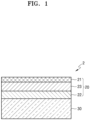
- FIG. 1 is a diagram showing a stacked structure of a multi-layered anode structure according to one or more embodiments.
- An anode structure 2 includes an anode 20 and a solid electrolyte 30, wherein the anode 20 has a structure in which a first anode active material layer 22 is arranged on an anode current collector 21 and a second anode active material layer 23 is arranged between the anode current collector 21 and the first anode active material layer 22. Pores may be formed in the first anode active material layer 22, and the first anode active material layer 22 may include a metal or a metal alloy, wherein the metal or the metal alloy may react with lithium to form a lithium compound or a lithium alloy.
- the lithium ion diffusivity of the first anode active material layer may be about 1 ⁇ 10 -14 cm 2 /sec or greater at 25°C, and may be controlled to be equal to or greater than the lithium ion diffusivity of the second anode active material layer.
- first anode active material layer 22 has a high lithium ion diffusivity by having a porous structure with a wide surface area, lithium introduced into the first anode active material layer 22 may move quickly to the second anode active material layer 23, so that local precipitation of lithium inside the first anode active material layer 22 or at the interface between the first anode active material layer 22 and the solid electrolyte 30 may be prevented or minimized.
- the lithium ion diffusivity of the first anode active material layer 22 at 25°C may be, for example, about 1 ⁇ 10 -14 cm 2 /sec or greater, about 1 ⁇ 10 -13 cm 2 /sec or greater, about 1 ⁇ 10 -12 cm 2 /sec or greater, about 1 ⁇ 10 -11 cm 2 /sec or greater, about 1 ⁇ 10 -10 cm 2 /sec or greater, or about 5 ⁇ 10 -10 cm 2 /sec or greater.
- the lithium ion diffusivity of the second anode active material layer 23 at 25°C may be, for example, about 1 ⁇ 10 -15 cm 2 /sec or greater, about 1 ⁇ 10 -14 cm 2 /sec or greater, about 1 ⁇ 10 -13 cm 2 /sec or greater, about 1 ⁇ 10 -12 cm 2 /sec or greater, about 1 ⁇ 10- 11 cm 2 /sec or greater, or about 5 ⁇ 10 -11 cm 2 /sec or greater.
- the first anode active material layer 22 may include the M 1 -M 2 O x composite, the Li-M 1 -M 2 O x composite, or a combination thereof.
- the lithium diffusion is high and the fluidity of particles is low, and thus stable interfacial contact may be maintained during charging and discharging cycles at a high rate.
- a phase with rapid lithium diffusion may be maintained.
- the first anode active material layer 22 may have a higher reduction potential of lithium ions than the solid electrolyte 30.
- the metal alloy included in the first anode active material layer 22 has a higher reduction potential of lithium ions at the time of charging than a solid electrolyte included in the solid electrolyte 30, a reductive decomposition reaction of the solid electrolyte may be suppressed. Accordingly, at the interface between the solid electrolyte 30 and the first anode active material layer 22, the decomposition of the solid electrolyte may be suppressed, and at the same time, the local precipitation of lithium may be suppressed, thereby forming a lithium precipitation layer with a uniform surface.
- the stability of the solid electrolyte 30 during charging and discharging cycles may be increased and the reversible precipitation/dissolution of the lithium precipitation layer may occur, and thus the short circuit of the all-solid-state secondary battery may be suppressed while having improved cycle characteristics.
- the reduction potential of lithium ions of the first anode active material layer refers to a potential for the metal or the metal alloy, which reacts with lithium to form a lithium alloy or a lithium compound, to reduce lithium ions to form a lithium-metal alloy such as a solid solution, wherein lithium is a material for forming the first anode active material layer 22. That is, the reduction potential of lithium ions refers to a potential maintained by the metal alloy during charging.
- the reduction potential of the solid electrolyte may refer to a potential at which a transition metal included in the solid electrolyte is reduced and a decomposition reaction of the solid electrolyte proceeds.
- the reduction potential of lithium ions of the first anode active material layer 22 may be, for example, about 0.05 Volts (V) to about 0.6 V (vs. Li + /Li).
- the reduction potential of lithium ions may refer to a reduction potential or a decomposition potential of the solid electrolyte.
- the reduction potential of LLZO may be about 0.05 V (vs. Li + /Li).
- a thickness of the first anode active material layer 22 may be about 10 nm to about 500 nm, about 15 nm to about 480 nm, about 20 nm to about 450 nm, about 30 nm to about 420 nm, and for example, about 50 nm to about 300 nm.
- an all-solid-state secondary battery having improved resistance and capacity characteristics may be prepared.
- the first anode active material layer 22 may be, for example, an inorganic layer that does not include an organic material.
- a side reaction caused by, for example, an organic material during charging and discharging cycles, may be suppressed.
- the Ge component of the metal alloy among the components of the first anode active material layer 22 may be mainly removed.
- the first anode active material layer may include a Li-Te-Ge compound, a Li-Te compound, a Li-Ge compound, a Li-Te-O compound, a Li-Te-Ge-O compound, or a combination thereof.
- the amount of Ge may be less than that of Te.
- the amount of Ge may be about 0.1 mole percent (mol%) to about 50 mol%, whereas the amount of Te may be about 20 mol% to about 90 mol%, each based on 100 mol% total. These amounts may be confirmed, for example, by EDX or XPS.
- a thickness ratio of the first anode active material layer 22 to the second anode active material layer 23 may be, for example, about 1:50 to about 1:100.
- FIG. 2 is a view of a structure of the all-solid-state battery according to one or more embodiments.
- the all-solid-state battery 1 includes a cathode 10 including a cathode active material layer 12; an anode 20; and a solid electrolyte 30 arranged between the cathode 10 and the anode 20, wherein the anode 20 includes: an anode current collector 21; a first anode active material layer 22 arranged on the anode current collector 21 and in contact with the solid electrolyte 30; and a second anode active material 23 arranged between the anode current collector 21 and the first anode active material layer 22.
- the first anode active material layer 22 may include a metal or a metal alloy that reacts with lithium to form a lithium compound or a lithium alloy
- the second anode active material layer 23 may include a carbon-containing anode active material only or a combination of a carbon-containing anode active material and at least one of a metal anode active material or metalloid anode active material.
- the lithium ion diffusivity of the first anode active material layer 22 may be controlled to be about 1 ⁇ 10 -14 cm 2 /sec or greater at 25°C. In addition, the lithium ion diffusivity of the first anode active material layer 22 may be controlled to be greater than or equal to that of the second anode active material layer 23.
- lithium introduced into the first anode active material layer 22 may move quickly to the second anode active material layer 23, and accordingly local precipitation of lithium inside the first anode active material layer 22 or at the interface between the first anode active material layer 22 and the solid electrolyte 30, may be prevented or minimized.
- the lithium ion diffusivity at 25°C of the first anode active material layer 22 may be, for example, about 1 ⁇ 10 -14 cm 2 /sec or greater, about 1 ⁇ 10 -13 cm 2 /sec or greater, about 1 ⁇ 10 -12 cm 2 /sec or greater, about 1 ⁇ 10 -11 cm 2 /sec or greater, about 1 ⁇ 10 -10 cm 2 /sec or greater, or about 5 ⁇ 10 -10 cm 2 /sec or greater.
- the lithium ion diffusivity at 25°C of the second anode active material layer 23 may be, for example, about 1 ⁇ 10 -15 cm 2 /sec or greater, about 1 ⁇ 10 -14 cm 2 /sec or greater, about 1 ⁇ 10 -13 cm 2 /sec or greater, about 1 ⁇ 10 -12 cm 2 /sec or greater, about 1 ⁇ 10 -11 cm 2 /sec or greater, or about 5 ⁇ 10 -11 cm 2 /sec or greater.
- the reduction potential of lithium ions of the composite constituting the first anode active material layer 22 may be controlled to be greater than the reduction potential of lithium ions of the solid electrolyte included in the solid electrolyte 30.
- a difference between the reduction potential of the lithium ions of the first anode active material layer 22 and the reduction potential of the solid electrolyte may be controlled to be, for example, about 0.01 V or greater, about 0.02 V or greater, about 0.05 V or greater, about 0.1 V or greater, about 0.2 V or greater, or about 0.3 V or greater.
- the reduction and decomposition reaction of the solid electrolyte may be effectively suppressed during charging and discharging.
- the reduction potential of lithium ions of the first anode active material layer 22 with respect to lithium metal may be, for example, about 0.05 V or greater, about 0.1 V or greater, about 0.2 V or greater, about 0.3 V or greater, about 0.4 V or greater, or about 0.5 V or greater.
- the reduction potential of the lithium ions of the metal alloy included in the first anode active material layer 22 may be, for example, about 0.05 V or greater, about 0.1 V or greater, about 0.2 V or greater, about 0.3 V or greater, about 0.4 V or greater, or about 0.5 V or greater.
- the reduction potential or reduction and decomposition potential of the solid electrolyte included in the solid electrolyte 30 with respect to lithium metal may be, for example, about 0.2 V or less, about 0.1 V or less, about 0.09 V or less, about 0.07 V or less, about 0.05 V or less, about 0.03 V or less, about 0.02 V or less, or about 0.01 V or less.
- solid electrolyte having a wide a wide electrochemically stable voltage window may be provided.
- the reduction potential of the first anode active material layer 22 may be greater than that of the second anode active material layer 23.
- the difference between the reduction potential of the lithium ions of the first anode active material layer 22 and the reduction potential of the lithium ions of the second anode active material layer 23 may be, for example, about 0.01 V or greater, about 0.02 V or greater, about 0.05 V or greater, about 0.1 V or greater, about 0.2 V or greater, or about 0.3 V or greater.
- a second metal included in the second anode active material layer 23 may be easily selected within a range having lower reduction potential of the lithium ions than the first anode active material layer 22 including a metal alloy.
- the reduction potential of the lithium ions of the Ge-Te metal alloy may be about 0.05 V to about 0.6 V.
- the reduction potential of lithium ions having silver (Ag) as the second metal may be about 0.2 V.
- the reduction potential of the lithium ions of the first anode active material layer 22 may be lower than the reduction potential of the lithium ions of the second anode active material layer 23.
- the reduction potential of the lithium ions of the first anode active material layer 22 may be higher than the reduction potential of the solid electrolyte, the reduction potential of the lithium ions of the first anode active material layer 22 may be lower than the reduction potential of the lithium ions of the second anode active material layer 23.
- the first anode active material layer 22 may include only a metal or a metal alloy, or may include a Li-containing metal or a Li-containing metal alloy layer.
- the thicknesses of the first anode active material layer 22 and the second anode active material layer 23 may each independently be, for example, about 50% or less, about 40% or less, about 30% or less, about 20% or less, or about 10% or less, of the thickness of the cathode active material layer 12.
- the all-solid-state secondary battery may have improved energy density.
- the thickness of the first anode active material layer 22 may be about 10 nm to about 500 nm, about 15 nm to about 480 nm, about 20 nm to about 450 nm, about 30 nm to about 420 nm, or for example, about 50 nm to about 300 nm.
- the thickness of the second anode active material layer 23 may be, for example, about 1 nm to 100 micrometer ( ⁇ m), about 10 nm to about 100 ⁇ m, about 100 nm to about 10 ⁇ m, about 1 ⁇ m to about 100 ⁇ m, about 5 ⁇ m to about 90 ⁇ m, about 10 ⁇ m to about 80 ⁇ m, about 15 ⁇ m to about 80 ⁇ m, about 20 ⁇ m to about 70 ⁇ m, about 20 ⁇ m to about 55 ⁇ m, about 1 nm to about 500 nm, about 10 nm to about 500 nm, about 10 nm to about 400 nm, about 10 nm to about 300 nm, about 10 nm to about 150 nm, or about 10 nm to about 100 nm.
- the first anode active material layer 22 and/or the second anode active material layer 23 may be arranged by, for example, a vacuum deposition method, a sputtering method, a plating method, or the like, but the method is not limited thereto. Any suitable method capable of forming an anode active material layer may be used.
- the second anode active material layer 23 may include, for example, an anode active material in the form of a particle and a binder.
- the average particle diameter of the anode active material in the form of particles included in the second anode active material layer 23 may be about 4 ⁇ m or less, about 3 ⁇ m or less, about 2 ⁇ m or less, about 1 ⁇ m or less, or about 900 nm or less.
- the average particle diameter of the anode active material in the form of particles may be, for example, about 10 nm to about 4 ⁇ m, about 10 nm to about 2 ⁇ m, about 10 nm to about 1 ⁇ m, or about 10 nm to about 900 nm.
- the average particle diameter of the second anode active material may be, for example, a median diameter (D50) measured by using a laser particle size distribution meter.
- the anode active material in the form of particles included in the second anode active material layer 23 may include, for example, i)a carbon-containing anode active material or ii) a carbon-containing anode active material, and at least one of a metal anode active material or a metalloid anode active material.
- the carbon-containing anode active material in the form of particles may be, in particular, amorphous carbon.
- the amorphous carbon may include, for example, at least one of carbon black (CB), acetylene black (AB), furnace black (FB), Ketjen black (KB), graphene, or the like, but is not necessarily limited thereto. Any suitable material available as amorphous carbon in the art may be used.
- the amorphous carbon may be carbon that does not have crystallinity or has very low crystallinity, and in this regard, may be distinguished from crystalline carbon or graphite-containing carbon.
- the metal or metalloid may include, for example, at least one of indium, silicon, gallium, tin, aluminum, titanium, zirconium, niobium, germanium, antimony, bismuth, zinc, gold, platinum, palladium, nickel, iron, cobalt, chromium, magnesium, cerium, cesium, or lanthanum.
- the second metal may include, for example, Au, Pt, Pd, Si, Ag, Al, Bi, Sn, Zn, Fe, Co, Cr, Cs, Ce, sodium (Na), potassium (K), calcium (Ca), yttrium (Y), Bi, tantalum (Ta), hafnium (Hf), barium (Ba), vanadium (V), strontium (Sr), La, or a combination thereof.
- Ni does not form an alloy with Li
- Ni is not a metal or metalloid anode active material.
- the second anode active material layer 23 may include, for example, one type of anode active material or a mixture of a plurality of different types of anode active material in the form of particles, among the anode active material in the form of particles.
- the first anode active material layer 22 may only include first particles consisting of amorphous carbon, or may further include second particles consisting of at least one metal of In, Si, Ga, Sn, Al, Ti, Zr, Nb, Ge, Sb, Bi, Zn, Au, Pt, Pd, Fe, Co, Cr, Mg, Ce, Cs, or La.
- the second anode active material layer 23 may include a mixture of first particles consisting of amorphous carbon, and second particles consisting of at least one metal of In, Si, Ga, Sn, Al, Ti, Zr, Nb, Ge, Sb, Bi, Zn, Au, Pt, Pd, Ni, Fe, Co, Cr, Mg, Ce, Cs, or La.
- the amount of the second particles may be about 8 wt% to about 60 wt%, about 10 wt% to about 50 wt%, about 15 wt% to about 40 wt%, or about 20 wt% to about 30 wt%, based on a total weight of the mixture of first particle and second particles. When the amount of the second particles is within the ranges above, for example, the cycle characteristics of the all-solid-state secondary battery 1 may be further improved.
- the second anode active material layer 23 may include only first particles consisting of amorphous carbon, or further include second particles consisting of at least one second metal of Au, Pt, Pd, Si, Ag, Al, Bi, Sn, or Zn.
- the second anode active material layer 23 may include a mixture of the first particles consisting of amorphous carbon, and the second particles consisting of a metal of Au, Pt, Pd, Si, Ag, Al, Bi, Sn, or Zn, wherein a mixing ratio of the amorphous carbon to the metal may be, for example, about 10:1 to about 1:2, about 5:1 to about 1:1, or about 4:1 to about 2:1.
- a mixing ratio is not limited within these ranges, and may be selected according to the required characteristics of the all-solid-state secondary battery 1.
- the anode active material included in the second anode active material layer 23 may include, for example, a mixture of the first particles consisting of amorphous carbon and the second particles consisting of a metal or a metalloid.
- the mixture may be a simple mixture of the first particles and the second particles, or a mixture of the first particles and the second particles that are physically bound together by a binder.
- the metal or the metalloid may include, for example, at least one of In, Si, Ga, Sn, Al, Ti, Zr, Nb, Ge, Sb, Bi, Au, Pt, Pd, Mg, Pd, Ag, or Zn.
- the metalloid may be, in other words, a semiconductor element.
- An amount of the second particle may be about 8 wt% to about 60 wt%, about 10 wt% to about 50 wt%, about 15 wt% to about 40 wt%, or about 20 wt% to about 30 wt%, based on the total weight of the mixture of first particle and second particles.
- the amount of the second particle is within the ranges above, the cycle characteristics of the all-solid-state secondary battery may be further improved.
- the second anode active material layer 23 may include, for example, a binder.
- the binder may be, for example, styrene-butadiene rubber (SBR), poly(tetrafluoroethylene), poly(vinylidene fluoride), polyethylene, vinylidene fluoride/hexafluoropropylene copolymer, polyacrylonitrile, poly(methyl methacrylate), or the like, but is not limited thereto. Any suitable material available as a binder may be used.
- the binder may be used alone, or may be used with a plurality of different binders.
- the second anode active material layer 23 When the second anode active material layer 23 includes the binder, the second anode active material layer 23 may be stabilized on the anode current collector 21. In addition, despite a change in volume and/or relative position of the second anode active material layer 23 during charging and discharging, cracking of the second anode active material layer 23 may be suppressed. For example, when the second anode active material layer 23 does not include the binder, the second anode active material layer 23 may be easily separated from the anode current collector 21.
- the second anode active material layer 23 may be prepared by, for example, coating the anode current collector 21 with a slurry in which a material constituting the second anode active material layer 23 is dispersed, and drying the coated anode current collector 21.
- the binder is included in the second anode active material layer 23, the anode active material may be stably dispersed in the slurry.
- clogging of the screen for example, clogging by an agglomerate of the anode electrode active material
- the anode current collector 21 may be formed of, for example, a material that does not react with lithium, in other words, a material that forms neither an alloy with lithium nor a compound with lithium.
- a material for forming the anode current collector 21 may be, for example, copper (Cu), stainless steel, Ti, Fe, Co, Ni, or the like, but is not limited thereto. Any suitable material available as an electrode current collector may be used.
- the anode current collector 21 may be formed of one of the above-described metals, or an alloy or coating material of two or more metals.
- the anode current collector 21 may be, for example, in the form of a plate or a foil.
- the second anode active material layer 23 may further include one or more additives, for example, a filler, a dispersant, an ion conductive agent, or the like, as used in a conventional all-solid-state battery.
- additives for example, a filler, a dispersant, an ion conductive agent, or the like, as used in a conventional all-solid-state battery.
- the thickness of the first anode active material layer 22 including the anode active material in the form of particles and/or the thickness of the second anode active material layer 23 may be, for example, about 50% or less, about 40% or less, about 30% or less, about 20% or less, or about 10% or less, of the thickness of the cathode active material layer 12.
- the all-solid-state secondary battery 1 may have improved energy density.
- a third anode active material layer may be arranged between the anode current collector 21 and the second anode active material layer 23 or between the first anode active material layer 22 and the second anode active material layer 23.
- the third anode active material layer may be a metal layer including lithium or a lithium alloy.
- the metal layer may include lithium or a lithium alloy.
- the third anode active material layer may be formed by a charging. Therefore, the third anode active material layer which is a metal layer including lithium may serve as, for example, a lithium reservoir.
- the lithium alloy may be, for example, a Li-Al alloy, a Li-Sn alloy, a Li-In alloy, a Li-Ag alloy, a Li-Au alloy, a Li-Zn alloy, a Li-Ge alloy, a Li-Si alloy, or the like, but is not limited thereto. Any suitable material alloyable with lithium may be used.
- the third anode active material layer may consist of lithium, one of the alloys above, or several kinds of alloys.
- a thickness of the third anode active material layer is not particularly limited, but may be, for example, about 1 ⁇ m to about 1,000 ⁇ m, about 1 ⁇ m to about 500 ⁇ m, about 1 ⁇ m to about 200 ⁇ m, about 1 ⁇ m to about 150 ⁇ m, about 1 ⁇ m to about 100 ⁇ m, or about 1 ⁇ m to about 50 ⁇ m.
- the third active material layer may be, for example, a metal foil having a thickness within the ranges above.
- the third anode active material layer 25 may be, for example, arranged between the anode current collector 21 and the second anode active material layer 23 or between the first anode active material layer 22 and the second anode active material layer 23, before assembling the all-solid-state secondary battery 1.
- the third anode active material layer may be, for example, precipitated between the anode current collector 21 and the second anode active material layer 23, or between the anode active material layer 22 and the second anode active material layer 23, by charging after the assembly of the all-solid-state secondary battery 1.
- the third anode active material layer is arranged between the anode current collector 21 and the second anode active material layer 23, or between the anode active material layer 22 and the second anode active material layer 23, before the assembly of the all-solid-state secondary battery 1, the third anode active material layer, which is a metal layer including lithium, may serve as a lithium reservoir. Accordingly, the cycle characteristics of the all-solid-state secondary battery 1 including the third anode active material layer may be further improved.
- a lithium foil may be arranged between the anode current collector 21 and the second anode active material layer 23, or between the first anode active material layer 22 and the second anode active material layer 23.
- the third anode active material layer is not included at the time of the assembly of the all-solid-state secondary battery 1, and thus the energy density of the all-solid-state battery 1 may increase.
- the charging capacity of the first anode active material layer 22 and the second anode active material layer 23 may be exceeded. That is, the first anode active material layer 22 and the second anode active material layer 23 may be overcharged.
- lithium may be absorbed in the first anode active material layer 22 and the second anode active material layer 23.
- the anode active materials included in the first anode active material layer 22 and the second anode active material layer 23 may form an alloy or compound with lithium ions that have migrated from the cathode 10.
- the first anode active material layer 22 and the second anode active material layer 23 are charged beyond the capacity thereof, for example, lithium may be precipitated on the rear surface of the second anode active material layer 23, i.e., between the anode current collector 21 and the second anode active material layer 23. Then, due to the precipitated lithium, a metal layer corresponding to the third anode active material layer may be formed.
- the first anode active material layer 22 and the second anode active material layer 23 are charged beyond the capacity thereof, for example, lithium may be precipitated on the front surface of the second anode active material layer 23, i.e., between the first anode active material layer 22 and the second anode active material layer 23. Then, due to the precipitated lithium, a metal layer corresponding to the third anode active material layer may be formed.
- the third anode active material layer may be a metal layer mainly including lithium (i.e., lithium metal).
- the anode active materials included in the first anode active material layer 22 and the second anode active material layer 23 consist of a material that forms an alloy or a compound with lithium.
- lithium included in the first anode active material layer 22, the second anode active material layer 23, and the third anode active material layer which is a metal layer may be ionized and move toward the cathode 10. Therefore, lithium may be used as the anode active material in the all-solid-state secondary battery 1.
- the first anode active material layer 22 and/or the second anode active material layer 23 coats the third anode active material layer
- the third anode active material layer 25 which is a metal layer may serve as a protective layer and serve to suppress the precipitation growth of lithium dendrites at the same time. Therefore, the short circuit and the capacity degradation of the all-solid-state secondary battery 1 may be suppressed, thereby improving the cycle characteristics of the all-solid-state secondary battery 1.
- the thickness of the first anode active material layer 22 may be, for example, about 5% to about 150%, about 10% to about 120%, about 20% to about 100%, about 30% to about 80%, or about 33% to about 66%, with respect to the thickness of the third anode active material layer in a state after charging.
- the function of the first anode active material layer 22 may not be appropriately performed.
- the energy density of the all-solid-state secondary battery 1 may be reduced.
- the anode current collector 21, the first anode active material layer 22, the second anode active material layer 23, and region therebetween may be, for example, lithium metal-free layers or regions that do not include lithium metal in an initial state or a post-discharge state of the all-solid-state secondary battery 1.
- the solid electrolyte 30 may include a solid electrolyte arranged between the cathode 10 and the anode 20.
- the solid electrolyte may include, for example, an oxide-containing solid electrolyte, a sulfide-containing solid electrolyte, or a combination thereof.
- the oxide-containing solid electrolyte may include one or more of Li 1+x+y Al x Ti 2-x Si y P 3-y O 12 , wherein 0 ⁇ x ⁇ 2 and 0 ⁇ y ⁇ 3; BaTiOs; Pb(Zr a Ti 1-a )O 3 , wherein 0 ⁇ a ⁇ 1 (PZT); Pb 1-x La x Zr 1-y Ti y O 3 , wherein 0 ⁇ x ⁇ 1 and 0 ⁇ y ⁇ 1 (PLZT); PB(Mg 3 Nb 2/3 )O 3 -PbTiO 3 (PMN-PT); HfO 2 ; SrTiO 3 ; SnO 2 ; CeO 2 ; Na 2 O; MgO; NiO; CaO; BaO; ZnO; ZrO 2 ; Y 2
- LiAlO 2 Li 2 O-Al 2 O 3 -SiO 2 -P 2 O 5 -TiO 2 -GeO 2 ; or Li 3+x La 3 M 2 O 12 , wherein M is Te, Nb, or Zr, and x is an integer from 1 to 10.
- the solid electrolyte may be prepared by a sintering method, or the like.
- the oxide-containing solid electrolyte may include a garnet-type solid electrolyte that is Li 7 La 3 Zr 2 O 12 (LLZO) and/or Li 3+x La 3 Zr 2-a M a O 12 (M-doped LLZO, M is Ga, W, Nb, Ta, or Al, and x is an integer from 1 to 10, 0.05 ⁇ a ⁇ 0.7).
- LLZO Li 7 La 3 Zr 2 O 12
- M-doped LLZO M is Ga, W, Nb, Ta, or Al
- x is an integer from 1 to 10, 0.05 ⁇ a ⁇ 0.7.
- the solid electrolyte may include, for example, a sulfide-containing solid electrolyte.
- the sulfide-containing solid electrolyte may include, for example, one or more of Li 2 S-P 2 S 5 , Li 2 S-P 2 S 5 -LiX, wherein X is a halogen, Li 2 S-P 2 S 5 -Li 2 O; Li 2 S-P 2 S 5 -Li 2 O-LiI; Li 2 S-SiS 2 ; Li 2 S-SiS 2 -LiI; Li 2 S-SiS 2 -LiBr; Li 2 S-SiS 2 -LiCI; Li 2 S-SiS 2 -B 2 S 3 -LiI; Li 2 S-SiS 2 -P 2 S 5 -LiI; Li 2 S-B 2 S 3 ; Li 2 S-P 2 S 5 -Z m S n , wherein m and n are positive numbers, and
- the sulfide-containing solid electrolyte may be, for example, prepared by treating a starting material, such as Li 2 S, P 2 S 5 , or the like) by a melting quenching method or a mechanical milling method, but embodiments are not limited thereto. Also, after such treatment, heat treatment may be performed.
- the sulfide-containing solid electrolyte may be amorphous or crystalline, or may be in a mixed state.
- the sulfide-containing solid electrolyte may include, for example, S, P, and Li, as at least constituent elements of the above-described sulfide-containing solid electrolyte material.
- the sulfide-containing solid electrolyte may be a material including Li 2 S-P 2 S 5 .
- a mixing molar ratio of Li 2 S to P 2 S 5 (Li 2 S:P 2 S 5 ) may be, for example, about 50:50 to about 90:10.
- the sulfide-containing solid electrolyte may include a compound having an argyrodite crystal-type structure.
- the compound having an argyrodite-type crystal structure may include, for example, one or more of Li 7-x PS 6-x Cl x , wherein 0 ⁇ x ⁇ 2; Li 7-x PS 6-x Br x , wherein 0 ⁇ x ⁇ 2; or Li 7-x PS 6-x I x , wherein 0 ⁇ x ⁇ 2.
- the sulfide-containing solid electrolyte included in the solid electrolyte may be an argyrodite-type compound including one or more of Li 6 PS 5 Cl, Li 6 PS 5 Br, or Li 6 PS 5 I.
- the solid electrolyte 30 may further include, for example, a binder.
- the binder included in the solid electrolyte 30 may be, for example, SBR, poly(tetrafluoroethylene), poly(vinylidene fluoride), polyethylene, or the like, or a combination thereof, but is not limited thereto. Any suitable material available as a binder may be used.
- the binder included in the solid electrolyte 30 may be the same as or different from the binders included in the cathode active material layer 12 and the first anode active material layer 22.
- the cathode 10 may include a cathode current collector 11 and a cathode active material layer 12.
- the cathode current collector 11 may be, for example, in the form of a plate or a foil, each including In, Cu, Mg, stainless steel, Ti, Fe, Co, Ni, Zn, Al, Ge, Li, or an alloy thereof.
- the cathode current collector 11 may be omitted.
- the cathode active material layer 12 may include, for example, a cathode active material.
- the cathode active material may be capable of reversibly absorbing or desorbing lithium ions.
- the cathode active material may include, for example, a lithium transition metal oxide, such as lithium cobalt oxide (LCO), a lithium nickel oxide, a lithium nickel cobalt oxide, a lithium nickel cobalt aluminum oxide (NCA), a lithium nickel cobalt manganese oxide (NCM), a lithium manganate, a lithium iron phosphate, or the like, a nickel sulfide, a copper sulfide, a lithium sulfide, an iron oxide, a vanadium oxide, or the like, but embodiments are not limited thereto. Any suitable material available as the cathode active material may be used.
- the cathode active material may be used alone or in a combination of two or more materials.
- the lithium transition metal oxide may be, for example, a compound represented by one of Li a A 1-b B b D 2 , wherein 0.90 ⁇ a ⁇ 1, and 0 ⁇ b ⁇ 0.5; Li a E 1-b B b O 2-c D c , wherein 0.90 ⁇ a ⁇ 1, 0 ⁇ b ⁇ 0.5, and 0 ⁇ c ⁇ 0.05; LiE 2-b B b O 4-c D c , wherein 0 ⁇ b ⁇ 0.5, and 0 ⁇ c ⁇ 0.05; Li a Ni 1-b-c Co b B c D ⁇ , wherein 0.90 ⁇ a ⁇ 1, 0 ⁇ b ⁇ 0.5, 0 ⁇ c ⁇ 0.05, and 0 ⁇ ⁇ ⁇ 2; Li a Ni 1-b-c Co b B c O 2- ⁇ F ⁇ , wherein 0.90 ⁇ a ⁇ 1, 0 ⁇ b ⁇ 0.5, 0
- a coating layer may be also added to the surface of the compound described above, and a mixture of the compound described above and a compound having a coating layer may be also used.
- a coating layer added to the surface of the compound described above may include, for example, a coating element compound such as an oxide of a coating element, a hydroxide of a coating element, an oxyhydroxide of a coating element, an oxycarbonate of a coating element, or a hydroxy carbonate of a coating element.
- a coating element compound constituting the coating layer may be amorphous or crystalline.
- the coating element included in the coating layer may include Mg, Al, Co, K, Na, Ca, Si, Ti, V, Sn, Ge, Ga, B, As, Zr, or a combination thereof.
- a method of forming the coating layer may be selected within a range that does not adversely affect the physical properties of the cathode active material.
- a coating method may include, for example, spray coating, dipping, or the like, but embodiments are not limited thereto.
- a specific coating method is well understood by those skilled in the art, and thus a detailed description thereof will be omitted.
- the cathode active material may include, for example, a lithium salt of a transition metal oxide having a layered rock salt type structure, among the lithium transition metal oxides described herein.
- layered rock salt type structure refers to, for example, a structure in which oxygen atomic layers and metal layers are alternately arranged regularly in the ⁇ 111> direction of a cubic rock salt type structure to form a two-dimensional plane by each of the atomic layers.
- cubic rock salt type structure refers to a NaCl type structure which is one type of crystal structures, and in detail, may refer to a structure in which a face centered cubic lattice (fcc) formed by respective anions and cations is misaligned from each other by 1/2 of the ridge of a unit lattice.
- fcc face centered cubic lattice
- the cathode active material includes a ternary lithium transition metal oxide having a layered rock salt type
- the all-solid-state secondary battery may have further improved energy density and thermal stability.
- the cathode active material may be covered by the coating layer as described herein.
- any suitable coating layer known for a cathode active material of an all-solid-state secondary battery may be used.
- the coating layer may be, for example, Li 2 O-ZrO 2 or the like.
- the cathode active material includes, for example, Ni as the ternary lithium transition metal oxide such as NCA or NCM
- the volume density of the all-solid-state secondary battery may increase so that the metal elution of the cathode active material may be reduced in a charged state. Consequently, the cycle characteristics of the all-solid-state secondary battery may be improved.
- the cathode active material may be in the form of, for example, a globular shape or an oval-sphere shape.
- a particle diameter of the cathode active material is not particularly limited and may be within a range applicable to a conventional all-solid secondary battery.
- the amount of the cathode active material in the cathode 10 is not particularly limited and may be within a range applicable to a cathode of a conventional all-solid-state battery.
- the cathode 10 may further include, in addition to the cathode active material, one or more additives such as a conductive material, a binder, a filler, a dispersant, an ion conductive auxiliary agent, or the like.
- the conductive material may include, for example, at least one of graphite, carbon black, acetylene black, Ketjen black, carbon fiber, metal powder, or the like.
- the binder may include, for example, at least one of SBR, poly(tetrafluoroethylene), poly(vinylidene fluoride), polyethylene, or the like.
- any suitable material generally used for a solid secondary battery may be used.
- the cathode 10 may further include a solid electrolyte.
- the solid electrolyte included in the cathode 10 may be similar to or different from the solid electrolyte included in the solid electrolyte 30. Details on the solid electrolyte may be understood by referring to the solid electrolyte 30.
- the solid electrolyte included in the cathode 10 may include, for example, an oxide-containing solid electrolyte, a sulfide-containing solid electrolyte, or a combination thereof.
- an oxide-containing solid electrolyte for use as the sulfide-containing solid electrolyte and the oxide-containing solid electrolyte, the sulfide-containing solid electrolyte and the oxide-containing solid electrolyte used for the solid electrolyte may be used.
- the cathode 10 may be, for example, impregnated with a liquid electrolyte.
- the liquid electrolyte may include a lithium salt and one or more of an ionic liquid or a polymer ionic liquid.
- the liquid electrolyte may be non-volatile.
- the ionic liquid may have a melting point that is less than room temperature, and may refer to a salt in a liquid state at room temperature or a molten salt at room temperature, each consisting of only ions.
- the ionic liquid may include a) one or more cations that are an ammonium cation, a pyrrolidinium cation, a pyridinium cation, a pyrimidinium cation, an imidazolium cation, a piperidinium cation, a pyrazolium cation, an oxazolium cation, a pyridazinium cation, a phosphonium cation, a sulfonium cation, a triazolium cation, or a combination thereof; or b) one or more anions that are BF 4 - , PF 6 - , AsF 6- , SbF 6 - , AlCl 4 - , HSO 4 - , ClO 4 - , CH 3 SO 3 - , CF 3 CO 2 - , Cl - , Br-, I - , SO 4 - , CF 3 SO 3
- the ionic liquid may include one or more of, for example, N-methyl-N-propylpyrrolidinium bis(trifluoromethanesulfonyl)imide, N-butyl-N-methylpyrrolidium bis(3-trifluoromethylsulfonyl)imide, 1-butyl-3-methylimidazolium bis(trifluoromethylsulfonyl)imide, or 1-ethyl-3-methylimidazolium bis(trifluoromethylsulfonyl)imide.
- the polymer ionic liquid may include a repeating unit including: a) one or more cations that are an ammonium cation, a pyrrolidinium cation, a pyridinium cation, a pyrimidinium cation, an imidazolium cation, a piperidinium cation, a pyrazolium cation, an oxazolium cation, a pyridazinium cation, a phosphonium cation, a sulfonium cation, a triazolium cation, or a combination thereof; and b) one or more anions that are BF 4 - , PF 6 - , AsF 6 - , SbF 6 -, AlCl 4 - , HSO 4 - , ClO 4 - , CH 3 SO 3 - , CF 3 CO 2 - , (CF 3 SO 2 ) 2 N - , (
- the lithium salt may include, for example, LiPF 6 , LiBF 4 , LiSbF 6 , LiAsF 6 , LiClO 4 , LiCF 3 SO 3 , Li(CF 3 SO 2 ) 2 N, Li(FSO 2 ) 2 N, LiC 4 F 9 SO 3 , LiAlO 2 , LiAlCl 4 , LiN(C x F 2x+1 SO 2 )(C y F 2y+1 SO 2 ) (where x and y are natural numbers), LiCl, Lil, or a combination thereof.
- the lithium salt included in the liquid electrolyte may have a concentration of about 0.1 molar (M) to about 5 M.
- An amount of the liquid electrolyte impregnated in the cathode 10 may be, based on 100 parts by weight of the cathode active material layer 12 not including the liquid electrolyte, about 0 parts by weight to about 100 parts by weight, about 0 parts by weight to about 50 parts by weight, about 0 parts by weight to about 30 parts by weight, about 0 parts by weight to about 10 parts by weight, or about 0.1 parts by weight to about 5 parts by weight.
- the all-solid-state secondary battery may be prepared by the steps of providing the solid electrolyte; arranging the first anode active material layer on a surface of the solid electrolyte; forming a plurality of pores in the first anode active material layer to form a porous first anode active material layer; arranging the anode current collector on the porous first anode active material layer, wherein a second anode active material is arranged on the anode current collector; and arranging the cathode active material layer on an opposite surface of the solid electrolyte.
- the step of arranging a first anode active material layer on a surface of the solid electrolyte may be performed by arranging a first anode active material layer precursor on a surface of the solid electrolyte.
- the first negative electrode active material layer precursor disposed on the solid electrolyte layer may be converted into the first negative electrode active material layer after charging and discharging.
- the forming of the plurality of pores in the first anode active material layer may be performed by acid treatment of the first anode active material layer or by treatment of the first anode active material layer by using a pore former.
- the first anode active material layer may have a porous structure with an increased surface area so that the diffusion and movement of lithium ions toward the second anode active material layer may increase, thereby improving the binding force between the solid electrolyte and the first anode active material layer.
- the pore former may include at least one of polyvinyl pyrrolidone (PVP), polyethylene glycol, polyvinyl alcohol, diethylglycol, polymethyl methacrylate (PMMA), or triethylene glycol.
- PVP polyvinyl pyrrolidone
- PMMA polymethyl methacrylate
- the arranging of the first anode active material layer on one surface of the solid electrolyte may be performed by stacking the first anode active material layer formed on a substrate on the solid electrolyte.
- the first anode active material layer may be formed on the substrate by deposition such as sputtering, drop coating, spray coating, or solution infiltration in an oxidizing gas atmosphere.
- the deposition may be, for example, accomplished by physiochemical vapor deposition.
- the oxidizing gas atmosphere may include an oxygen atmosphere or air atmosphere.
- the deposition may include sputtering, pulsed laser deposition (PLD), molecular beam epitaxy (MBE), ion plating, ion beam deposition, or the like.
- PLD pulsed laser deposition
- MBE molecular beam epitaxy
- ion plating ion beam deposition, or the like.
- the sputtering may include, for example, DC sputtering, radio frequency (RF) sputtering, magnetron sputtering, bias sputtering, or reactive sputtering, but embodiments are not limited thereto. In one or more embodiments, RF sputtering may be used.
- DC sputtering DC sputtering
- RF radio frequency
- magnetron sputtering magnetron sputtering
- bias sputtering bias sputtering
- reactive sputtering reactive sputtering
- the first anode active material layer may include an oxide of the metal alloy, such as an oxide of a Ge x Te y alloy (wherein 0 ⁇ x ⁇ 2 and 0 ⁇ y ⁇ 1.5) or an oxide of a Ge x Te y alloy (wherein 0 ⁇ x ⁇ 1 and 0 ⁇ y ⁇ 1).
- an oxide of the metal alloy such as an oxide of a Ge x Te y alloy (wherein 0 ⁇ x ⁇ 2 and 0 ⁇ y ⁇ 1.5) or an oxide of a Ge x Te y alloy (wherein 0 ⁇ x ⁇ 1 and 0 ⁇ y ⁇ 1).
- the metal alloy may include at least one of Ge 1 Te 1 , Ge 0.35 Te 0.65 (Ge 0.7 Te 1.3 ), Ge 0.5 Te 1 (Ge 1 Te 2 ), Ge 0.54 Te 1 (Ge 1.08 Te 2 ), Ge 0.6 Te 1 (Ge 1.2 Te 2 ), Ge 0.65 Te 1 (Ge 1.3 Te 2 ), Ge 0.7 Te 1 (Ge 1.4 Te 2 ), Ge 0.75 Te 1 (Ge 1.5 Te 2 ), Ge 0.8 Te 1 (Ge 1.6 Te 2 ), Ge 0.85 Te 1 (Ge 1.7 Te 2 ), Ge 0.9 Te 1 (Ge 1.8 Te 2 ), Ge 0.95 Te 1 (Ge 1.9 Te 2 ), and Ge 2 Te 3 .
- the mixing molar ratio of the first metal to the second metal in the metal alloy may be about 1:1 to about 1:500, about 1:1 to about 1:300, about 1:1 to about 1:200, about 1:5 to about 1:180, about 1:8 to about 1:100, or about 1:1.85 to about 1:50.
- the metal alloy may include, for example, a GeTe binary alloy.
- the metal alloy may have low fluidity compared to monometallic metal such as silver, and thus may maintain stable interfacial contact during high-rate charging and discharging. Even after alloying/dealloying with lithium, a phase (rhombohedral structure) having rapid lithium diffusion may be maintained, so that the metal alloy may not serve as a kinetic barrier.
- the first anode active material layer includes the above-mentioned metal alloy, the short circuit of the all-solid-state secondary battery may be prevented, thereby improving the cycle characteristics of the all-solid-state secondary battery.
- the molar ratio of Ge to Te may be in about 2.5:1 to about 1:500, about 1:1 to about 1:500, about 1:1 to about 1:300, about 1:1 to about 1:200, about 1:5 to about 1:180, about 1:8 to about 1:150, or about 1:10 to about 1:130, before performing the acid treatment.
- the molar ratio of Ge to Te in the Ge-Te alloy may be 0:1.
- the molar ratio of Ge to Te in the Ge-Te alloy may be about 1:1.5 to about 1:100, about 1:5 to about 1:50, about 1:7 to about 1:30, or about 1:8 to about 1:20.
- the substrate is not particularly limited, and for example, various supports including a base, an anode electrode, or the like may be used depending on a manufacturing process.
- the conditions for the sputtering process may include RF power of about 300 watts (W) to about 500 W, a power density of about 2.5 watts per square centimeter (W/cm 2 ) to about 2.6 W/cm 2 , a working pressure of about 3 mTorr to about 9 mTorr, and nitrogen or argon gas as plasma gas.
- the growth rate at which the first anode active material layer may be formed on the substrate may be controlled to be in a range of about 0.3 angstroms per second ( ⁇ /sec) to about 0.4 ⁇ /sec.
- the distance between the sputter target and the substrate may be about 50 nm to about 120 nm, and a deposition time may be about 100 minutes (min) to about 1,000 min.
- a dense first anode active material layer may be formed.
- a dense first anode active material layer in an amorphous or crystalline state may be formed.
- the heat treatment may not be performed. In one or more embodiments, after performing the sputtering, a heat treatment may be performed.
- the heat treatment may be further performed at 400°C or less, or at a temperature of about 100°C to about 400°C, for example, about 200°C to about 400°C. As such, when the heat treatment is further performed, the content of the crystalline phase in the first anode active material layer may be increased.
- the heat treatment may be further performed thereon at a temperature of about 200°C to about 400°C. As such, when the heat treatment is further performed, the crystallinity of the metal alloy may be further improved.
- lithium ions may move smoothly.
- the all-solid-state secondary battery 1 may be prepared in a way that, for example, the solid electrolyte 30 on which the first anode active material layer 22 and the second anode active material layer 23 are sequentially stacked and the cathode 10 are each prepared first, and then stacked.
- the first anode active material layer may be prepared by coating the metal alloy on a surface of the solid electrolyte according to a sputtering method, a vacuum deposition method, a coating method, or the like.
- the first anode active material layer may be prepared by arranging a foil of the metal alloy on one surface of the solid electrolyte and pressing the resultant.
- the pressing may include, for example, roll pressing, flat pressing, warm isotactic pressing (WIP), cold isotactic pressing (CIP), or the like, but is not particularly limited thereto. Any suitable pressing method available may be used.
- the pressure applied during the pressing may be, for example, about 50 megapascal (MPa) to about 500 MPa.
- the time for which the pressing is applied may be about 5 milliseconds (ms) to about 10 min.
- the pressing may be, for example, performed at a temperature of about room temperature to about 90°C, or about 20°C to about 90°C. Alternatively, the pressing may be performed at a high temperature of about 100°C or greater.
- the second anode active material layer may be prepared in the same manner as in the first anode active material layer, except that the second metal may be used. By arranging the anode current collector on the second anode active material layer and then pressing the resultant, a laminate of solid electrolyte 30/anode 20 may be prepared.
- the pressing may include, for example, roll pressing, flat pressing, or the like, but is not limited thereto.
- the pressure applied during the pressing may be, for example, in a range of about 50 MPa to about 500 MPa.
- the time for which the pressing is applied may be in a range of about 5 ms to about 10 min.
- the pressing may be, for example, performed at a temperature in a range of about room temperature to about 90°C or about 20°C to 90°C. Alternatively, the pressing may be performed at a high temperature of 100°C or greater.
- the second anode active material layer 23 may be prepared by using a slurry for the second anode active material.
- the slurry may be prepared by adding components constituting the second anode active material layer 23, such as a particle of the carbon-containing anode active material, a binder, or the like, to a polar solvent or a non-polar solvent.
- the prepared slurry may be applied onto the first anode active material layer 22 of the first laminate of solid electrolyte 30/first anode active material layer 22, and then dried to prepare a second laminate.
- the anode current collector 21 may be arranged on the dried second laminate, and the pressing may be applied thereto as described herein, thereby preparing a laminate of solid electrolyte 30/anode 20.
- a slurry may be prepared by adding materials constituting the cathode active material layer 12, such as a cathode active material, a binder, or the like, to a non-polar solvent.
- the prepared slurry may be applied onto the cathode current collector 11, and then dried.
- the pressing is performed on a laminate thus obtained to prepare the cathode 10.
- the pressing may include, for example, roll pressing, flat pressing, hydrostatic pressing, or the like, but is not limited thereto. Any suitable pressing method may be used.
- the pressing may be omitted.
- the cathode 10 may be prepared by compacting and molding a mixture of the materials constituting the cathode active material layer 12 in the form of pellets or by extending the mixture in a sheet form. When the cathode 10 is prepared by the methods above, the cathode current collector 11 may be omitted. Alternatively, the cathode 10 may be prepared as being impregnated with an electrolyte solution.
- the solid electrolyte 30 including the oxide-containing solid electrolyte may be, for example, prepared by performing heat treatment on a precursor of an oxide-containing solid electrolyte material.
- the oxide-containing solid electrolyte may be prepared by contacting the precursor in a stoichiometric amount to form a mixture and by performing heat treatment thereon.
- the contact may include, for example, milling including ball milling or pulverizing.
- the mixture of precursors mixed with a stoichiometric composition may be subjected to first heat treatment in an oxidizing atmosphere to prepare a product of the first treatment.
- the first heat treatment may be performed at 1,000°C or less, for 1 hour to 36 hours.
- the product of the first heat treatment may be pulverized.
- the pulverization of the product of the first heat treatment may be performed in a dry condition or a wet condition.
- the wet pulverization may be, for example, performed by mixing the product of the first heat treatment with a solvent such as methanol and performing ball milling thereon for about 0.5 hour to about 10 hours.
- the dry pulverization may be performed by ball milling without using a solvent.
- the particle diameter of the pulverized product of the first heat treatment may be about 0.1 ⁇ m to about 10 ⁇ m, or about 0.1 ⁇ m to about 5 ⁇ m.
- the pulverized product of the first heat treatment may be dried.
- the pulverized product of the first heat treatment may be mixed with a binder solution and then molded into pellets, or may be simply pressed at a pressure of about 1 ton to about 10 tons, and then molded into pellets.
- the molded product may be subjected to second heat treatment at a temperature of less than or equal to about 1,000°C for about 1 hour to about 36 hours. Accordingly, the solid electrolyte 30 which is a sintered product of the second heat treatment may be obtained.
- the second heat treatment may be performed at a temperature of about 550°C to about 1,000°C.
- the second heat treatment may be performed for about 1 hour to about 36 hours.
- the temperature at which the second heat treatment temperature is performed may be greater than the temperature at which the first heat treatment temperature is performed.
- the temperature at which the second heat treatment is performed may be greater than the temperature at which the first heat treatment is performed by about 10°C or more, about 20 °C or more, about 30 °C or more, or about 50 °C or more.
- the molded product may be subjected to the second heat treatment in at least one of an oxidizing atmosphere and a reducing atmosphere.
- the second heat treatment may be performed in a) an oxidizing atmosphere, b) a reducing atmosphere, or c) a combination of an oxidizing atmosphere and a reducing atmosphere.
- the solid electrolyte 30 including the sulfide-containing solid electrolyte may be, for example, prepared by using a solid electrolyte formed of a sulfide-containing solid electrolyte material.
- the sulfide-containing solid electrolyte may be formed by, for example, treating a starting source material with a melt quenching method or a mechanical milling method, but the methods are not limited thereto. Any suitable method available as a preparation method for the sulfide-containing solid electrolyte may be used. For example, in the case of using the melt quenching method, a small amount of starting source materials such as Li 2 S, P 2 S 5 , or the like may be mixed, pelletized, reacted at a predetermined reaction temperature in a vacuum state, and then quenched to prepare the sulfide-containing solid electrolyte material.
- starting source materials such as Li 2 S, P 2 S 5 , or the like may be mixed, pelletized, reacted at a predetermined reaction temperature in a vacuum state, and then quenched to prepare the sulfide-containing solid electrolyte material.
- reaction temperature of the mixture of Li 2 S and P 2 S 5 may be, for example, about 400°C to about 1,000°C, or about 800°C to about 900°C.
- the reaction time may be, for example, about 0.1 hour to about 12 hours, or about 1 hour to about 12 hours.
- the quenching temperature of the reactants may be about 10°C or less, or about 0°C or less, and the quenching rate of the reactants may be about 1°C/sec to about 10,000°C/sec, or about 1°C/sec to about 1,000°C/sec.
- the sulfide-containing solid electrolyte material may be prepared by stirring and reacting the starting source materials such as Li 2 S, P 2 S 5 , or the like, using a ball mill.
- the stirring rate and stirring time for the mechanical milling method are not particularly limited. However, the faster stirring rate leads to the faster production rate of the sulfide-containing solid electrolyte material, and the longer stirring time leads to the higher conversion rate of the source materials into the sulfide-containing solid electrolyte material.
- the mixed source materials obtained by a melt quenching method, a mechanical milling method, or the like may be heat-treated at a predetermined temperature, and then pulverized to prepare the solid electrolyte in the form of particles.
- the solid electrolyte has glass transition characteristics, the amorphous state of the solid electrolyte may be changed to the crystalline state.
- the solid electrolyte prepared by the method above may be, for example, deposited by using a known film forming method such as aerosol deposition, cold spray, sputtering, or the like, to prepare the solid electrolyte 30.
- the solid electrolyte 30 may be prepared by pressing the particles of the solid electrolyte.
- the solid electrolyte may be mixed with a solvent and a binder, and the mixture may be coated, dried, and pressed to prepare the solid electrolyte 30.
- the cathode 10 and the laminate of anode 20/solid electrolyte 30 prepared as described above may be stacked in a way that the solid electrolyte 30 may be arranged between the cathode 10 and the anode 20, and then pressed to prepare the all-solid-state secondary battery 1.
- the laminate of anode 20/solid electrolyte 30 may be arranged on the cathode 10 in a way that the cathode 10 is in contact with the solid electrolyte 30 to prepare a second laminate. Then, the second laminate may be pressed to prepare the all-solid-state secondary battery 1.
- the pressing may include, for example, roll pressing, flat pressing, hydrostatic pressing, or the like, but is not limited thereto. Any pressing method available in the art may be used.
- the pressure applied during the pressing may be, for example, about 50 MPa to about 750 MPa.
- the time for which the pressing is applied may be about 5 ms to about 5 min.
- the pressing may be, for example, performed at a temperature of about room temperature to about 90°C, or about 20 °C to 90 °C. Alternatively, the pressing may be performed at a high temperature of 100°C or greater.
- the configuration and manufacturing method of the all-solid-state secondary battery 1 described above is an example of the embodiment, and structural members, manufacturing procedures, and the like may be appropriately varied. The pressing may be omitted.
- Example 1 Preparation of NCA (5.1 mAh/cm 2 )/LLZO pellet (500 ⁇ m)/Te-TeO x (50 nm)/AgC (7 ⁇ m)/Li (20 ⁇ m)
- An LLZO pellet (Li 7 La 3 Zr 2 O 12 ) having a thickness of 500 ⁇ m was prepared as a solid electrolyte.
- a GeTeO x (1.0 ⁇ x ⁇ 3) alloy film (particularly, a Ge 1.0 Te 0.5 O 2.4 film) was formed to a thickness of about 50 nm through RF sputtering using a GeTe target on the LLZO pellet in an oxygen atmosphere to form a laminate in which a first anode active material layer was arranged on the solid electrolyte.
- a mixed atomic ratio (mixed molar ratio) of Ge to Te was 2:1.
- process conditions included 200 W of power, 1,800 seconds of sputtering time, and use of N 2 (1.1 kPa) as a plasma gas.
- an stainless steel (SUS) foil was coated with a slurry for the second anode active material layer, and then dried at room temperature (25°C) for 1 hour to form a second anode active material layer on the SUS foil (also referred to as an AgC layer, thickness of about 7 ⁇ m).
- SUS stainless steel
- the slurry for the second anode active material layer was prepared as follows.
- carbon black (CB) having a primary particle diameter of about 38 nm and Ag particles having an average particle diameter of about 100 nm were prepared.
- the LLZO layer on which the first anode active material layer (also referred to as the metal alloy layer, i.e., the Ge 2 Te 1 film) was formed was subjected to acid treatment to prepare a structure of the first anode active material layer (Te-TeO 2 composite film) having pores formed therein the LLZO film.
- the amount of Te was about 57.4 parts by weight and the amount of TeO 2 was about 42.6 parts by weight, each based on 100 parts by weight of the total weight of the Te-TeO 2 composite.
- a 1 M hydrochloric acid aqueous solution was used for use as an acidic solution used in the acid treatment. After dipping for 10 second, the acidic solution was washed off with ethanol.
- the second anode active material layer (also referred to as the AgC layer) was arranged on the first anode active material layer of the structure of the first anode active material layer/LLZO layer, and the SUS foil was removed by cold isotactic pressing (CIP) treatment. Then, on the resultant structure, a lithium metal foil (thickness of 20 ⁇ m) and a copper foil as an anode current collector were contacted again by applying a pressure of 250 MPa at 25°C by CIP treatment to prepare a laminate consisting of solid electrolyte/first anode active material layer/second anode active material layer/lithium metal/copper thin film.
- CIP cold isotactic pressing
- LiNi 0.8 Co 0.15 Al 0.05 O 2 was prepared as a cathode active material.
- poly(tetrafluoroethylene) (Dupont's TEFLON binder (registered trademark)) was prepared as a binder.
- a carbon nanofiber (CNF) was prepared as a conductive agent.
- the cathode active material, the conductive agent, and the binder were mixed at a weight ratio of 100:2:1, to prepare a mixture.
- the mixture was stretched in the form of a sheet to prepare a cathode active material sheet.
- the cathode active material sheet was compressed on a cathode current collector consisting of an aluminum foil having a thickness of 18 ⁇ m to prepare a cathode.
- the cathode active material layer of the cathode thus prepared was impregnated with an electrolyte solution in which 2.0 M of lithium bis(fluorosulfonyl)imide (LiFSI) was dissolved in N-propyl-N-methyl-pyrrolidinium bis(fluorosulfonyl)imide (PYR13FSI), which is an ionic liquid.
- LiFSI lithium bis(fluorosulfonyl)imide
- PYR13FSI N-propyl-N-methyl-pyrrolidinium bis(fluorosulfonyl)imide
- the cathode was arranged in an SUS cap in a way that the cathode active material impregnated with the electrolyte solution was placed on top.
- the laminate of solid electrolyte/anode to which the anode was attached was arranged in a way that the solid electrolyte was arranged on the cathode active material layer, and then, the resultant laminate was sealed to prepare an all-solid-state secondary battery.
- the cathode and the anode were each insulated with an insulator. A portion of each of the cathode current collector and the anode current collector was protruded to the outside of the sealed battery cell to be used as a cathode terminal and an anode terminal.
- the first anode active material layer included, after charging and discharging, Li a -Te x -Te y O 2 (wherein 0 ⁇ a ⁇ 5, 0 ⁇ x ⁇ 3, and 0 ⁇ y ⁇ 2), wherein, in Li a -Te x -Te y O 2 (wherein 0 ⁇ a ⁇ 5, 0 ⁇ x ⁇ 3, and 0 ⁇ y ⁇ 2), the amount of Li was 10 parts by weight, the amount of Te was 55 parts by weight, and the amount of TeO 2 was 35 parts by weight, based on 100 parts by weight of the total weight of Li a -Te x -Te y O 2 composite
- An all-solid-state secondary battery was prepared in a similar manner as in Example 1, except that LiCoO 2 was used instead of LiNi 0.8 Co 0.15 Al 0.05 O 2 (NCA) as the cathode active material in forming the cathode active material layer.
- LiCoO 2 was used instead of LiNi 0.8 Co 0.15 Al 0.05 O 2 (NCA) as the cathode active material in forming the cathode active material layer.
- An all-solid-state secondary battery was prepared in a similar manner as in Example 1, except that an LLZO tape (thickness: 80 ⁇ m) was used instead of the LLZO (Li 7 La 3 Zr 2 O 12 ) having a thickness 500 ⁇ m as the solid electrolyte.
- Example 4 Preparation of NCA (5.1 mAh/cm 2 )/LLZO pellet (500 ⁇ m)/LiTeTeO 2 (100 nm)/carbon (7 ⁇ m)/Li (20 ⁇ m)
- a second anode active material layer (also referred to as the C layer)(thickness: about 7 ⁇ m) was formed on the SUS foil in a similar manner as in Example 1, except that a slurry for a second anode active material layer obtained by the following procedure was used as the slurry for the second anode active material layer.
- Example 5 Preparation of NCA (5.1 mAh/cm 2 )/LLZTO pellet (500 ⁇ m)/Te-ZnO x (50 nm)/AgC (7 um)/Li (20 um)
- An LLZO pellet (Li 7 La 3 Zr 2 O 12 ) having a thickness of 500 ⁇ m was prepared as a solid electrolyte.
- a GeTeZnO x (wherein 1.0 ⁇ x ⁇ 3) alloy film (particularly, a Ge 1.0 Te 0.5 Zn 0.41 O 2.4 film) was formed to a thickness of about 50 nm through RF sputtering using GeTe and Zn targets on the LLZO pellet in an oxygen atmosphere to form a laminate in which a first anode active material layer was arranged on the solid electrolyte.
- a mixed atomic ratio (mixed molar ratio) of Ge to Te was 2:1.
- process conditions included GeTe target power of 1500 W, Zn target power of 100 W, 10 minutes of sputtering time, and the use of Ar (40 standard cubic centimeters per minute (sccm)) and O 2 (10 sccm) as a plasma gas.
- Ar 40 standard cubic centimeters per minute (sccm)
- O 2 10 sccm
- an SUS foil was coated with a slurry for the second anode active material layer, and then dried at room temperature (25°C) for 1 hour to form a second anode active material layer on the SUS foil (also referred to as AgC layer, thickness: about 7 ⁇ m).
- the slurry for the second anode active material layer was prepared as follows.
- CB having a primary particle diameter of about 38 nm and Ag particles having an average particle diameter of about 100 nm were prepared.
- the LLZO layer on which the first anode active material layer (also referred to as the metal alloy layer, i.e., the Ge 2 Te 1 Zn y film) was formed was subject to acid treatment to prepare a structure of the first anode active material layer having pores formed therein (Te-ZnO 2 composite film)(thickness of 50 nm)/LLZO film.
- Te-ZnO 2 composite film the amount of Te was about 61 parts by weight and the amount of ZnO 2 was about 39 parts by weight, based on 100 parts by weight of the total weight of the Te-ZnO 2 composite.
- an acidic solution used in the acid treatment a 1 M hydrochloric acid aqueous solution was used. After dipping for 1 second, the acidic solution was washed off with ethanol.
- the second anode active material layer (also referred to as the AgC layer) was arranged on the first anode active material layer of the structure of the first anode active material layer/LLZO layer, and the SUS foil was removed by CIP treatment. Then, on the resultant structure, a lithium metal foil (thickness of 20 ⁇ m) and a copper foil as an anode current collector contacted again by applying a pressure of 250 MPa at 25°C by CIP treatment to prepare a laminate consisting of solid electrolyte/first anode active material layer/second anode active material layer/lithium metal/copper thin film.
- LiNi 0.8 Co 0.15 Al 0.05 O 2 was prepared as a cathode active material.
- poly(tetrafluoroethylene) (Dupont's TEFLON binder (registered trademark)) was prepared as a binder.
- a carbon nanofiber (CNF) was prepared as a conductive agent.
- the cathode active material, the conductive agent, and the binder were mixed at a weight ratio of 100:2:1, to prepare a mixture.
- the mixture was stretched in the form of a sheet to prepare a cathode active material sheet.
- the cathode active material sheet was compressed on a cathode current collector consisting of an aluminum foil having a thickness of 18 ⁇ m to prepare a cathode.
- the cathode active material layer of the cathode thus prepared was impregnated with an electrolyte solution in which 2.0 M of LiFSI was dissolved in PYR13FSI.
- the cathode was arranged in an SUS cap in a way that the cathode active material that was impregnated with the electrolyte solution was placed on top.
- the laminate of solid electrolyte/anode to which the anode was attached was arranged in a way that the solid electrolyte was arranged on the cathode active material layer, and then, the resultant laminate was sealed to prepare an all-solid-state secondary battery.
- the cathode and the anode were each insulated with an insulator. A portion of each of the cathode current collector and the anode current collector was protruded to the outside of the sealed battery cell to be used as a cathode terminal and an anode terminal, respectively.
- the first anode active material layer included, after charging and discharging, Li a- Te x- Zn y O 2 (wherein 0 ⁇ a ⁇ 5, 0 ⁇ x ⁇ 3, and 0 ⁇ y ⁇ 2), wherein, in Li a- Te x- Zn y O 2 , the amount of Li was 10 parts by weight, the amount of Te was 55 parts by weight, and the amount of ZnO 2 was 35 parts by weight, based on 100 parts by weight of the total weight of the Li a- Te x- Zn y O 2 composite.
- a first anode active material layer was arranged on the solid electrolyte in the same manner as in Example 1, except that a GeTe alloy film (Ge 1 Te 0.5 film) was formed instead of the GeTeO x alloy film (Ge 1 Te 0.5 O 2.4 film).
- a GeTe alloy film Ge 1 Te 0.5 film
- process conditions included the argon atmosphere, 200 W of power, 1,800 seconds of sputtering time, and the use of N 2 (1.1 kPa) as a plasma gas.
- An all-solid-state secondary battery was prepared in a similar manner as in Reference Example 1, except that a Te film was formed instead of the GeTe film.
- process conditions included the argon atmosphere, 200 W of power, 1,800 seconds of sputtering time, and the use of N 2 (1.1 kPa) as a plasma gas.
- a Te-rich GeTe film was formed to a thickness of about 100 nm through RF sputtering using GeTe targets on an LLZO pellet in an argon atmosphere to form a laminate in which a first anode active material layer was arranged on the solid electrolyte.
- a mixed atomic ratio (mixed molar ratio) of Ge to Te was 1:2.
- process conditions included 200 W of power, 1,800 seconds of sputtering time, and the use of N 2 (1.1 kPa) as plasma gas. Accordingly, an all-solid-state secondary battery was prepared in a similar manner as in Example 1, except that the GeTe film was formed.
- Comparative Example 4 Poreless TeOx/carbon/Li NCA (5.1 mAh/cm 2 )/LLZO pellet (500 ⁇ m)/LiTeO x (100 nm)/carbon layer/Li (20 ⁇ m)
- An LLZO pellet (Li 7 La 3 Zr 2 O 12 ) having a thickness of 500 ⁇ m was prepared as a solid electrolyte.
- a TeO x alloy film was formed to a thickness of about 100 nm through RF sputtering using Te as a target on the LLZO pellet in an oxygen atmosphere to form a laminate in which a first anode active material layer was arranged on the solid electrolyte.
- process conditions included 200 W of power, 1,800 seconds of sputtering time, and the use of N 2 (1.1 kPa) as a plasma gas.
- an SUS foil was coated with a slurry for the second anode active material layer, and then dried at room temperature (25°C) for 1 hour to form a second anode active material layer on the SUS foil (also referred to as the AgC layer, thickness of about 7 ⁇ m).
- the slurry for the second anode active material layer was prepared as follows.
- the second anode active material layer (also referred to as the C layer) was arranged on the first anode active material layer of the structure of the first anode active material layer/LLZO layer, and the SUS foil was removed by CIP treatment. Then, on the resultant structure, a lithium metal foil (thickness of 20 ⁇ m) and a copper foil as an anode current collector were contacted again by applying a pressure of 250 MPa at 25°C by CIP treatment to prepare a laminate consisting of solid electrolyte/first anode active material layer/second anode active material layer/lithium metal/copper thin film.
- LiNi 0.8 Co 0.15 Al 0.05 O 2 was prepared as a cathode active material.
- poly(tetrafluoroethylene) (Dupont's TEFLON binder (registered trademark)) was prepared as a binder.
- a carbon nanofiber (CNF) was prepared as a conductive agent.
- the cathode active material, the conductive agent, and the binder were mixed at a weight ratio of 100:2:1, to prepare a mixture.
- the mixture was stretched in the form of a sheet to prepare a cathode active material sheet.
- the cathode active material sheet was compressed on a cathode current collector consisting of an aluminum foil having a thickness of 18 ⁇ m to prepare a cathode.
- the cathode active material layer of the cathode thus prepared was impregnated with an electrolyte solution in which 2.0 M of LiFSI was dissolved in PYR13FSI.
- the cathode was arranged in an SUS cap in a way that the cathode active material that was impregnated with the electrolyte solution was placed on top.
- the laminate of solid electrolyte/anode to which the anode was attached was arranged in a way that the solid electrolyte was arranged on the cathode active material layer, and then, the resultant laminate was sealed to prepare an all-solid-state secondary battery.
- the cathode and the anode were each insulated with an insulator. A portion of each of the cathode current collector and the anode current collector was protruded to the outside of the sealed battery cell to be used as a cathode terminal and an anode terminal, respectively.
- An all-solid-state secondary battery was prepared in a similar manner as in Example 1, except that the AgC layer was not formed between the Te-TeO x film (50 nm) and the lithium layer.
- FIG. 10A shows the impedance characteristics of the all-solid-state secondary battery of Example 4.
- the overall resistance was measured.
- the impedance was also measured according to the two-probe technique using an impedance analyzer (Solartron 1400A/1455A impedance analyzer).
- the frequency range was from about 0.1 Hz to about 1 MHz, and the amplitude voltage was about 10 mV.
- the measurement was performed at 25°C in the air atmosphere. Nyquist plots for the impedance measurement results are shown in FIG. 14A .
- the charging and discharging characteristics were evaluated by the following charging and discharging test.
- the charging and discharging test was performed by putting the all-solid-state secondary battery in a thermostatic bath at 25°C.
- the all-solid-state secondary batteries were charged with a constant current of 0.4 milliamperes per square centimeter (mA/cm 2 ) until a battery voltage reached 4.3 V. Subsequently, the all-solid-state secondary batteries were discharged with a constant current of 0.4 mA/cm 2 until a battery voltage reached 2.8 V.
- the all-solid-state secondary batteries were charged with a constant current of 0.5 mA/cm 2 until a battery voltage reached 4.3 V. Subsequently, the all-solid-state secondary batteries were discharged with a constant current of 0.5 mA/cm 2 until a battery voltage reached 2.8 V.
- the all-solid-state secondary batteries were charged with a constant current of 0.8 mA/cm 2 until a battery voltage reached 4.3 V. Subsequently, the all-solid-state secondary batteries were discharged with a constant current of 0.8 mA/cm 2 until a battery voltage reached 2.8 V.
- the all-solid-state secondary batteries were charged with a constant current of 1.0 mA/cm 2 until a battery voltage reached 4.3 V. Subsequently, the all-solid-state secondary batteries were discharged with a constant current of 1.0 mA/cm 2 until a battery voltage reached 2.8 V.
- the all-solid-state secondary batteries were charged with a constant current of 1.6 mA/cm 2 until a battery voltage reached 4.3 V. Subsequently, the all-solid-state secondary batteries were discharged with a constant current of 1.5 mA/cm 2 until a battery voltage reached 2.8 V.
- the all-solid-state secondary batteries were charged with a constant current of 2.0 mA/cm 2 until a battery voltage reached 4.3 V. Subsequently, the all-solid-state secondary batteries were discharged with a constant current of 2.0 mA/cm 2 until a battery voltage reached 2.8 V.
- the all-solid-state secondary batteries were charged with a constant current of 2.5 mA/cm 2 until a battery voltage reached 4.3 V. Subsequently, the all-solid-state secondary batteries were discharged with a constant current of 2.5 mA/cm 2 until a battery voltage reached 2.8 V.
- FIGS. 3B , 4B , 5B , and 6B Some of the charging and discharging test results are shown in FIGS. 3B , 4B , 5B , and 6B .
- the all-solid-state secondary batteries were charged with a constant current of 0.4 mA/cm 2 until a battery voltage reached 4.5 V. Subsequently, the all-solid-state secondary batteries were discharged with a constant current of 0.4 mA/cm 2 until a battery voltage reached 2.8 V.
- the all-solid-state secondary batteries were charged with a constant current of 0.8 mA/cm 2 until a battery voltage reached 4.5 V. Subsequently, the all-solid-state secondary batteries were discharged with a constant current of 0.8 mA/cm 2 until a battery voltage reached 2.8 V.
- the all-solid-state secondary batteries were charged with a constant current of 1.2 mA/cm 2 until a battery voltage reached 4.5 V. Subsequently, the all-solid-state secondary batteries were discharged with a constant current of 1.2 mA/cm 2 until a battery voltage reached 2.8 V.
- the all-solid-state secondary batteries were charged with a constant current of 1.6 mA/cm 2 until a battery voltage reached 4.5 V. Subsequently, the all-solid-state secondary batteries were discharged with a constant current of 1.6 mA/cm 2 until a battery voltage reached 2.8 V.
- the all-solid-state secondary batteries were charged with a constant current of 0.3 mA/cm 2 until a battery voltage reached 4.2 V. Subsequently, the all-solid-state secondary batteries were discharged with a constant current of 0.3 mA/cm 2 until a battery voltage reached 2.8 V.
- the all-solid-state secondary batteries were charged with a constant current of 0.6 mA/cm 2 until a battery voltage reached 4.2 V. Subsequently, the all-solid-state secondary batteries were discharged with a constant current of 0.6 mA/cm 2 until a battery voltage reached 2.8 V.
- the all-solid-state secondary batteries were charged with a constant current of 0.8 mA/cm 2 until a battery voltage reached 4.2 V. Subsequently, the all-solid-state secondary batteries were discharged with a constant current of 0.8 mA/cm 2 until a battery voltage reached 2.8 V.
- the all-solid-state secondary batteries were charged with a constant current of 1.0 mA/cm 2 until a battery voltage reached 4.2 V. Subsequently, the all-solid-state secondary batteries were discharged with a constant current of 1.0 mA/cm 2 until a battery voltage reached 2.8 V.
- the all-solid-state secondary batteries were charged with a constant current of 1.2 mA/cm 2 until a battery voltage reached 4.2 V. Subsequently, the all-solid-state secondary batteries were discharged with a constant current of 1.2 mA/cm 2 until a battery voltage reached 2.8 V.
- the all-solid-state secondary batteries were charged with a constant current of 1.5 mA/cm 2 until a battery voltage reached 4.2 V. Subsequently, the all-solid-state secondary batteries were discharged with a constant current of 1.5 mA/cm 2 until a battery voltage reached 2.8 V.
- the all-solid-state secondary batteries were charged with a constant current of 1.8 mA/cm 2 until a battery voltage reached 4.2 V. Subsequently, the all-solid-state secondary batteries were discharged with a constant current of 1.8 mA/cm 2 until a battery voltage reached 2.8 V.
- the all-solid-state secondary batteries were charged with a constant current of 2.0 mA/cm 2 until a battery voltage reached 4.2 V. Subsequently, the all-solid-state secondary batteries were discharged with a constant current of 2.0 mA/cm 2 until a battery voltage reached 2.8 V.
- the all-solid-state secondary batteries were charged with a constant current of 2.5 mA/cm 2 until a battery voltage reached 4.2 V. Subsequently, the all-solid-state secondary batteries were discharged with a constant current of 2.5 mA/cm 2 until a battery voltage reached 2.8 V.
- the all-solid-state secondary battery of Example 1 had improved charging and discharging characteristics as compared to the all-solid-state secondary battery of Comparative Example 5.
- the charge/discharge profile was evaluated under the following conditions.
- the charging and discharging test was performed by putting the all-solid-state secondary battery in a thermostatic bath at 25°C.
- the all-solid-state secondary battery was charged with a constant current of 0.3 mA/cm 2 until a battery voltage reached 4.2 V. Subsequently, the all-solid-state secondary battery was discharged with a constant current of 0.3 mA/cm 2 until a battery voltage reached 2.8 V.
- the all-solid-state secondary battery was charged with a constant current of 0.6 mA/cm 2 until a battery voltage reached 4.2 V. Subsequently, the all-solid-state secondary battery was discharged with a constant current of 0.6 mA/cm 2 until a battery voltage reached 2.8 V.
- the all-solid-state secondary battery was charged with a constant current of 0.8 mA/cm 2 until a battery voltage reached 4.2 V. Subsequently, the all-solid-state secondary battery was discharged with a constant current of 0.8 mA/cm 2 until a battery voltage reached 2.8 V.
- the all-solid-state secondary battery was charged with a constant current of 1.0 mA/cm 2 until a battery voltage reached 4.2 V. Subsequently, the all-solid-state secondary battery was discharged with a constant current of 1.0 mA/cm 2 until a battery voltage reached 2.8 V.
- the all-solid-state secondary battery was charged with a constant current of 1.2 mA/cm 2 until a battery voltage reached 4.2 V. Subsequently, the all-solid-state secondary battery was discharged with a constant current of 1.2 mA/cm 2 until a battery voltage reached 2.8 V.
- the all-solid-state secondary battery was charged with a constant current of 1.5 mA/cm 2 until a battery voltage reached 4.2 V. Subsequently, the all-solid-state secondary battery was discharged with a constant current of 1.5 mA/cm 2 until a battery voltage reached 2.8 V.
- the all-solid-state secondary battery was charged with a constant current of 1.8 mA/cm 2 until a battery voltage reached 4.2 V. Subsequently, the all-solid-state secondary battery was discharged with a constant current of 1.8 mA/cm 2 until a battery voltage reached 2.8 V.
- the all-solid-state secondary battery was charged with a constant current of 2.0 mA/cm 2 until a battery voltage reached 4.2 V. Subsequently, the all-solid-state secondary battery was discharged with a constant current of 2.0 mA/cm 2 until a battery voltage reached 2.8 V.
- the all-solid-state secondary battery was charged with a constant current of 2.5 mA/cm 2 until a battery voltage reached 4.2 V. Subsequently, the all-solid-state secondary battery was discharged with a constant current of 2.5 mA/cm 2 until a battery voltage reached 2.8 V.
- the all-solid-state secondary battery of Example 5 exhibited excellent charging and discharging characteristics.
- the charging and discharging characteristics were evaluated by the following charging and discharging test.
- the charging and discharging test was performed by putting the all-solid-state secondary batteries in a thermostatic bath at 25°C.
- the all-solid-state secondary batteries were charged with a constant current of 0.4 mA/cm 2 until a battery voltage reached 4.3 V. Subsequently, the all-solid-state secondary batteries were discharged with a constant current of 0.4 mA/cm 2 until a battery voltage reached 2.8 V.
- the all-solid-state secondary batteries were charged with a constant current of 0.5 mA/cm 2 until a battery voltage reached 4.3 V. Subsequently, the all-solid-state secondary batteries were discharged with a constant current of 0.5 mA/cm 2 until a battery voltage reached 2.8 V.
- the charging and discharging was repeatedly performed up to the number of cycles shown in 3C, 4C, 5C, and 6C respectively under the same charging and discharging conditions as in the second cycle.
- FIGS. 3C , 4C , 5C , and 6C Some of the charging and discharging test results are shown in FIGS. 3C , 4C , 5C , and 6C .
- the charging and discharging characteristics of the all-solid-state secondary batteries of Example 2 and Comparative Example 3 were evaluated by the following charging and discharging test.
- the charging and discharging test was performed by putting the all-solid-state secondary batteries in a thermostatic bath at 25°C.
- the all-solid-state secondary batteries were charged with a constant current of 0.2 mA/cm 2 until a battery voltage reached 4.3 V. Subsequently, the all-solid-state secondary batteries were discharged with a constant current of 0.2 mA/cm 2 until a battery voltage reached 2.8 V. The rate characteristics were examined while increasing the current density from a 0.2 mA/cm 2 step to a 1.6 mA/cm 2 step and 4 mA/cm 2 step under the charging and discharging condition of the first cycle.
- the examination results are shown in FIG. 7 .
- the charging and discharging characteristics of the all-solid-state secondary batteries of Example 2 and Comparative Example 3 were evaluated by the following charging and discharging test.
- the charging and discharging test was performed by putting the all-solid-state secondary batteries in a thermostatic bath at 25°C.
- the all-solid-state secondary batteries were charged with a constant current of 2.2 mA/cm 2 until a battery voltage reached 4.3 V. Subsequently, the all-solid-state secondary batteries were discharged with a constant current of 2.2 mA/cm 2 until a battery voltage reached 2.8 V. The charging and discharging was repeatedly performed up to a total of 1,000 cycles under the same charging and discharging conditions as in the first cycle.
- the all-solid-state secondary batteries were charged with a constant current of 3 mA/cm 2 until a battery voltage reached 4.3 V. Subsequently, the all-solid-state secondary batteries were discharged with a constant current of 3 mA/cm 2 until a battery voltage reached 2.8 V. The charging and discharging was repeatedly performed up to a total of 1,300 cycles under the same charging and discharging conditions as in the 1001st cycle.
- FIGS. 8 and 9 Some of the charging and discharging test results are shown in FIGS. 8 and 9 . As shown in FIGS. 8 and 9 , it was confirmed that the all-solid-state secondary battery of Example 2 exhibited excellent lifespan characteristics at room temperature over 1,000 times, and that the all-solid-state secondary battery of Example 3 could be driven at 2 mA/cm 2 for more than 1000 times and was also driven at 3 mA/cm 2 without a short circuit. It was found that the all-solid-state secondary battery of Example 3 had improved lifespan characteristics at room temperature compared to the all-solid-state secondary battery of Comparative Example 5.
- X-ray photoelectron spectroscopy was performed by using the THERMO K-Alpha XPS system.
- the spot size was 400 ⁇ m, and the resolution was 0.1 eV.
- the reaction and chemical bonding state at the interlayer interface according to lithium migration may be examined.
- the XPS using laboratory-based Al K ⁇ source (1486.6 eV) may provide information of photoelectrons detected up to 10 nm in general. Therefore, in a structure including an electrode for driving charging and discharging, the analysis at the interlayer interface is not possible.
- a diffusion phenomenon of lithium ions according to electron beam (ion beam) irradiation was used to analyze the reaction at the interlayer interface according to the movement of Li-ions.
- a sample is electrically neutralized by using an electron beam and an Ar +- ion beam to eliminate a charging phenomenon of the sample.
- real-time measurement was carried out by irradiating an electron beam for a certain period of time to raise lithium ions above the interlayer, or by irradiating an ion beam to lower lithium ions from the surface.
- the Ge component was etched after the surface was acid-treated, resulting in a structure in which TeO 2 (TeOx)(0 ⁇ x ⁇ 2) oxide was mixed with Te-metal.
- Table 1 shows the XPS results for the Te3d5 and O1s of the composite on the analysis of the first negative active material layer in a region having an intermediate thickness in the first anode active material layer (i.e., at a point of about 10 nm in the surface area of the first anode active material layer adjacent to the solid electrolyte) when measuring by sputtering at an average depth of 0.1 nm per second.
- an all-solid-state secondary battery that prevents a short circuit by suppressing a phenomenon in which metal is diffused in an electrode during high-temperature charging and discharging and that has improved cycle characteristics may be prepared.
- an all-solid-state secondary battery simultaneously secures rate characteristics and lifespan characteristics under high-capacity and high-current-density driving conditions.
Abstract
Description
- The present subject matter relates to an all-solid-state secondary battery and a method of preparing the same.
- Recently, the development of batteries with high energy density and safety has been actively carried out in response to industrial demands. For example, lithium-ion batteries are being put to practical use not only in the fields of information-related devices and communication devices, but also in the fields of automobiles. In the fields of automobiles, safety is considered especially important as it is related to protecting life.
- Lithium-ion batteries currently available on the market use a liquid electrolyte containing a flammable organic solvent, and thus overheating and fire may occur in the case of a short circuit. In this regard, all-solid-state secondary batteries using a solid electrolyte instead of a liquid electrolyte have been proposed.
- All-solid-state batteries do not contain a flammable organic solvent, and thus the possibility of fire or explosion may be greatly reduced even in the case of a short circuit. Therefore, such all-solid-state secondary batteries may significantly increase stability compared to lithium-ion batteries using a liquid electrolyte.
- In all-solid-state secondary batteries in the art, an electrolyte used is solid, and thus lithium may locally be deposited at an interface between a solid electrolyte layer and an anode. The deposited lithium may grow and consequently penetrate a solid electrolyte layer, resulting in a short circuit of the battery. In addition, as the solid electrolyte layer and the anode are simply stacked, the effective interface area between the solid electrolyte layer and the anode becomes smaller than the actual contact area therebetween. Accordingly, as the interfacial resistance increases at the interface between the solid electrolyte layer and the anode, the internal resistance of the battery may increase, thereby degrading the cycle characteristics and capacity of the battery.
- Provided is an all-solid-state secondary battery in which a short circuit is prevented during charging and discharging, and cycle characteristics are improved.
- Provided is a method of preparing the all-solid-state secondary battery as described herein.
- Additional aspects will be set forth in part in the detailed description that follows and, in part, will be apparent from the detailed description, or may be learned by practice of the presented exemplary embodiments.
- According to an aspect, an all-solid-state secondary battery includes:
- a cathode including a cathode active material,
- an anode including an anode current collector, a first anode active material layer, and a second anode active material layer, and
- a solid electrolyte arranged between the cathode and the anode,
- wherein the first anode active material layer is arranged adjacent to the solid electrolyte and includes an M1-M2Ox composite, a Li-M1-M2Ox composite, or a combination thereof,
- wherein M1 is a first metal and M2 is a second metal,
- the first metal and the second metal are each independently at least one element that reacts with lithium to form a lithium alloy or a lithium compound, and x is a number greater than 0, and
- the second anode active material layer is arranged between the anode current collector and the first anode active material layer, the second anode active material layer includes a second anode active material, and the second active material layer includes a carbon-containing anode active material, or a carbon-containing anode active material, and a metallic anode active material or a metalloid anode active material.
- According to another aspect, a method of preparing the all-solid-state secondary battery includes
- providing a solid electrolyte,
- arranging a first anode active material layer on a surface of the solid electrolyte,
- forming a plurality of pores in the first anode active material layer to prepare a porous first anode active material layer,
- arranging an anode current collector on the porous first anode active material layer, wherein a second anode active material is arranged on the anode current collector, and
- arranging a cathode active material layer on an opposite surface of the solid electrolyte.
- The above and other aspects, features, and advantages of certain exemplary embodiments will be more apparent from the following detailed description taken in conjunction with the accompanying drawings, in which:
-
FIG. 1 is a cross-sectional view of an anode structure for an all-solid-state secondary battery according to one or more embodiments; -
FIG. 2 is a cross-sectional view of an anode structure for an all-solid-state secondary battery according to another embodiment; -
FIGS. 3A ,4A ,5A , and6A are Nyquist plots of imaginary impedance (Z", ohm square centimeters (ohm cm2)) versus real impedance (Z', ohm cm2) and are graphs showing impedance characteristics of the all-solid-state secondary batteries of Example 1, Reference Example 1, Comparative Example 1, and Comparative Example 2, respectively; -
FIGS. 3B ,4B ,5B , and6B are graphs of potential (Volts (V) versus Li+/Li) versus capacity (milliampere hours per square centimeter (mAh/cm2)) and show charging and discharging characteristics of the all-solid-state secondary batteries of Example 1, Reference Example 1, Comparative Example 1, and Comparative Example 2, respectively; -
FIGS. 3C ,4C ,5C , and6C are graphs of capacity (mAh/cm2) versus number of cycles (times) and show charging and discharging characteristics at room temperature of the all-solid-state secondary batteries of Example 1, Reference Example 1, Comparative Example 1, and Comparative Example 2, respectively; -
FIG. 7 is a graph of capacity (mAh/cm2) versus numbers of cycles (times) and shows lifespan characteristics of the all-solid-state secondary batteries of Example 3 and Comparative Example 3; -
FIG. 8 is a graph of capacity (mAh/cm2) versus numbers of cycles (times) and shows lifespan characteristics of all-solid-state secondary battery of Example 3; -
FIG. 9 is a graph of potential (V vs. Li+/Li) versus capacity (mAh/cm2) and shows charging and discharging characteristics of all-solid-state secondary batteries of Example 3, based on the results of a charging and discharging test; -
FIG. 10A is a Nyquist plot of imaginary impedance (Z", ohm cm2) versus real impedance (Z', ohm cm2) and shows impedance characteristics of an all-solid-state secondary battery of Example 4; -
FIG. 10B is a graph of capacity (mAh/cm2) versus number of cycles (times) and shows lifespan characteristics of an all-solid-state secondary battery of Example 4; -
FIG. 11A is a Nyquist plot of imaginary impedance (Z", ohm cm2) versus real impedance (Z', ohm cm2) and shows impedance characteristics of the all-solid-state secondary batteries of Example 1 and Comparative Example 4; -
FIG. 11B is a graph of capacity (mAh/cm2) versus number of cycles (times) and shows lifespan characteristics of the all-solid-state secondary batteries of Example 1 and Comparative Example 4; -
FIG. 12A is a Nyquist plot of imaginary impedance (Z", ohm cm2) versus real impedance (Z', ohm cm2) and shows impedance characteristics of the all-solid-state secondary batteries of Example 1 and Comparative Example 5; -
FIGS. 12B and12C are graphs of potential (V vs. Li+/Li) versus capacity (mAh/cm2) and each shows charge/discharge profiles of all-solid-state secondary batteries of Example 1 and Comparative Example 5, respectively; -
FIGS. 13A and13B are graphs of intensity (arbitrary units, a.u.) versus binding energy (electron Volts, eV) and each shows X-ray photoelectron spectra of Ge 2p3 and Te3d in a GeTe film/LLZTO (oxide solid electrolyte)/Li/Cu (current collector) structure; -
FIG. 14A is a Nyquist plot of imaginary impedance (Z", ohm cm2) versus real impedance (Z', ohm cm2) and shows impedance characteristics of the all-solid-state secondary battery of Example 5; and -
FIG. 14B is a graph of potential (V vs. Li+/Li) versus capacity (mAh/cm2) and shows a potential change according to the capacity per unit area in the all-solid-state secondary battery of Example 5. - Reference will now be made in further detail to exemplary embodiments, examples of which are illustrated in the accompanying drawings, wherein like reference numerals refer to like elements throughout. In this regard, the present exemplary embodiments may have different forms and should not be construed as being limited to the detailed descriptions set forth herein. Accordingly, the exemplary embodiments are merely described in further detail below, and by referring to the figures, to explain certain aspects. As used herein, the term "and/or" includes any and all combinations of one or more of the associated listed items. Expressions such as "at least one of," when preceding a list of elements, modify the entire list of elements and do not modify the individual elements of the list.
- The terminology used herein is for the purpose of describing one or more exemplary embodiments only and is not intended to be limiting. As used herein, the singular forms "a," "an," and "the" are intended to include the plural forms as well, unless the context clearly indicates otherwise. The term "or" means "and/or." It will be further understood that the terms "comprises" and/or "comprising," or "includes" and/or "including" when used in this specification, specify the presence of stated features, regions, integers, steps, operations, elements, and/or components, but do not preclude the presence or addition of one or more other features, regions, integers, steps, operations, elements, components, and/or groups thereof.
- It will be understood that, although the terms first, second, third etc. may be used herein to describe various elements, components, regions, layers, and/or sections, these elements, components, regions, layers, and/or sections should not be limited by these terms. These terms are only used to distinguish one element, component, region, layer, or section from another element, component, region, layer, or section. Thus, a first element, component, region, layer, or section discussed below could be termed a second element, component, region, layer, or section without departing from the teachings of the present embodiments.
- Exemplary embodiments are described herein with reference to cross section illustrations that are schematic illustrations of idealized embodiments. As such, variations from the shapes of the illustrations as a result, for example, of manufacturing techniques and/or tolerances, are to be expected. Thus, embodiments described herein should not be construed as limited to the particular shapes of regions as illustrated herein but are to include deviations in shapes that result, for example, from manufacturing. For example, a region illustrated or described as flat may, typically, have rough and/or nonlinear features. Moreover, sharp angles that are illustrated may be rounded. Thus, the regions illustrated in the figures are schematic in nature and their shapes are not intended to illustrate the precise shape of a region and are not intended to limit the scope of the present claims.
- It will be understood that when an element is referred to as being "on" another element, it can be directly in contact with the other element or intervening elements may be present therebetween. In contrast, when an element is referred to as being "directly on" another element, there are no intervening elements present.
- Unless otherwise defined, all terms (including technical and scientific terms) used herein have the same meaning as commonly understood by one of ordinary skill in the art to which this general inventive concept belongs. It will be further understood that terms, such as those defined in commonly used dictionaries, should be interpreted as having a meaning that is consistent with their meaning in the context of the relevant art and the present disclosure, and will not be interpreted in an idealized or overly formal sense unless expressly so defined herein.
- "About" or "approximately" as used herein is inclusive of the stated value and means within an acceptable range of deviation for the particular value as determined by one of ordinary skill in the art, considering the measurement in question and the error associated with measurement of the particular quantity (i.e., the limitations of the measurement system). For example, "about" can mean within one or more standard deviations, or within ± 30%, 20%, 10%, 5% of the stated value.
- Hereinafter, an anode structure for an all-solid-state secondary battery according to one or more embodiments, an all-solid-state secondary battery including the same, and a method of preparing the all-solid-state secondary battery will be described in more detail.
- An aspect provides an all-solid-state secondary battery including:
- a cathode including a cathode active material;
- an anode including an anode current collector, a first anode active material layer, and a second anode active material layer; and
- a solid electrolyte arranged between the cathode and the anode.
- The first anode active material layer is arranged adjacent to the solid electrolyte, and includes:
- an M1-M2Ox composite, a Li-M1-M2Ox composite, or a combination thereof,
- wherein M1 is a first metal and M2 is a second metal,
- wherein the second anode active material layer is arranged between the anode current collector and the first anode active material layer, the second anode active material layer comprises a second anode active material, and the second anode active material includes a carbon-containing anode active material, or a carbon-containing anode active material, and a metallic anode active material or a metalloid anode active material, and
- In addition, since the anode including the carbon-containing anode active material in the all-solid-state secondary battery does not have an excellent binding force with a solid electrolyte, thus interfacial stability between the anode and the solid electrolyte may not be sufficient. In addition, in the case where an anode consists of a metal only, current imbalance may occur due to agglomeration of particles in a process of alloying and dealloying with lithium during charging and discharging cycles, and accordingly, an alloy phase having low lithium diffusion may be formed and some of the high rate characteristics may be degraded. In addition, when a metal diffuses within an electrode during charging and discharging cycles at a high temperature, the lifespan characteristics of an all-solid-state secondary battery may be degraded.
- The all-solid-state secondary battery according to one or more embodiments is provided to solve the above-mentioned problems. Since the first anode active material layer in contact with the solid electrolyte includes the M1-M2Ox composite, the Li-M1-M2Ox composite, or a combination thereof, void formation or volume changes may be suppressed at high current density during charging and discharging cycles, and the all-solid-state secondary battery is controlled to have a pore structure with a large surface area, thereby obtaining an effect of widening a surface diffusion path, and thus a lithium diffusion rate increases in a solution with a pH of 7 or less.
- In this regard, by controlling the lithium ion diffusivity of the first anode active material layer, the movement of lithium ions from the first anode active material layer to the second anode active material layer may be controlled to be fast. In addition, an adhesion force between the solid electrolyte and the second anode active material layer arranged to be in contact with the anode current collector may be improved. In addition, as described herein, the void formation at high current density during charging and discharging cycles may be suppressed, and thus the rate characteristics and the lifespan characteristics may be improved.
- In the M1-M2Ox composite and the Li-M1-M2Ox composite, the first metal M1 may be a material inducing a reversible alloying/dealloying reaction with lithium, and M2Ox, which is an oxide of the second metal M2, may serve as a backbone matrix and may have a role in the uniform induction and the suppression of the void formation during charging and discharging cycles.
- In the M1-M2Ox composite and the Li-M1-M2Ox composite, the first metal (M1) and the second metals (M2) may each independently refer to an element that maintains a solid state in a solution with a pH of 7 or less, and may each have a lithium ion diffusivity of 1×10-14 square centimeters per second (cm2/sec) or greater at 25°C. Here, the term "metal" used herein includes at least one selected metal and metalloid. For example, the first metal (M1) and the second metals (M2) may each be a metal that is alloyable with lithium,
- The first metal and the second metal, M1 and M2, may be identical to (the same as) or different from each other, and may each independently be Si, Sn, Ag, Al, Zn, Ge, Mg, Te, Pb, As, Na, Bi, Ti, B, W, Mn, Fe, Ni, Cu, Cr, Zr, Ce, or a combination thereof.
- The M1-M2Ox composite and the Li-M1-M2Ox composite may each be prepared by coating and treating a metal (e.g., Te, Si, Ge, Sb, or the like) or a metal alloy (e.g., GeTe, or the like). Component analysis of these composites may be performed by resonance Raman spectroscopy, X-photoelectron spectroscopy (XPS), transmission electron microscopy (TEM), energy dispersed X-ray (EDX) electron energy loss spectroscopy (EELS), inductively coupled plasma-mass spectroscopy (ICP-MS), or the like.
- In the M1-M2Ox composite and the Li-M1-M2Ox composite, for example, 0<x≤2.
- In the M1-M2Ox composite and the Li-M1-M2Ox composite, the first and second metals M1 and M2 may be the same as or different from each other, and the composite may include, for example, Te-TeOx, wherein 0<x≤2; Lia-Tex-TeyO2, wherein 0<a≤5, 0<x≤3, and 0<y≤2; Li-Te-TeOx, wherein 0<x≤2; Te-ZnOx; wherein 0<x≤2; Lia-Tex-ZnyO2, wherein 0<a≤5, 0<x≤3, and 0<y≤2; or Li-Te-ZnOx, wherein 0<x≤2.
- In the M1-M2Ox composite, an amount of M2Ox may be about 0.05 parts by weight to about 50 parts by weight, based on 100 parts by weight of the total weight of the M1-M2Ox composite. In the M1-M2Ox composite, the amount of M2Ox may be about 0.1 parts by weight to about 48 parts by weight, about 1 parts by weight to about 45 parts by weight, or about 5 parts by weight to about 43 parts by weight, based on 100 parts by weight of the total weight of the M1-M2Ox composite. When the amount of M2Ox is within the ranges above, a binding force between the solid electrolyte and the anode active material layer may increase, and accordingly, the void formation at high current density during charging and discharging cycles may be suppressed, and the volume changes may be reduced. As a result, the all-solid-state secondary battery having improved rate characteristics and long-lifespan characteristics may be prepared.
- In the Li-M1-M2Ox (wherein 0<x≤2) composite, an amount of the lithium may be about 0.01 parts by weight to about 80 parts by weight, based on 100 parts by weight of a total weight of the Li-M1-M2Ox composite, an amount of M1 may be about 10 parts by weight to about 70 parts by weight, based on 100 parts by weight of the total weight of the Li-M1-M2Ox composite, and an amount of M2Ox may be about 0.05 parts by weight to about 50 parts by weight, based on 100 parts by weight of the total weight of the Li-M1-M2Ox composite. When the amounts of Li, M1, and M2Ox are within the ranges above, the binding force between the solid electrolyte and the anode active material layer may increase, and accordingly, the void formation at high current density during charging and discharging cycles may be suppressed, and the volume changes may be reduced. As a result, the all-solid-state secondary battery having improved rate characteristics and long-lifespan characteristics may be prepared.
- A thickness of the first anode active material layer may be about 10 nanometers (nm) to about 500 nm, and the first anode active material layer may include a plurality of pores (i.e., two or more pores).
- Then, a second anode active material may be included in the pores of the first anode active material layer. In one or more embodiments, at least one of the plurality of pores may include the second anode active material disposed therein.
- In one or more embodiments, the first anode active material layer may includes a plurality of pores, at least one of the plurality of pores comprises the second anode active material disposed therein, and a porosity of the first anode active material layer is less than the porosity of the first anode active material layer that does not comprise the second anode active material disposed therein, or the first anode active material layer is non-porous by incorporation of the second anode active material. For example, after pressing the all-solid-state secondary battery, the second anode active material included in the second anode active material layer may be provided in at least one of the pores of the first anode active material layer so that porosity of the first anode active material layer may be reduced, or the pores may disappear (i.e., the first anode active material layer may become non-porous by incorporation of the second anode active material in the pores thereof). In one or more embodiments, a size of the plurality of pores in the first anode active material layer may be about 3 nm to about 50 nm. In other words, at least one pore of the plurality of pores may have a size of about 3 nm to about 50 nm.
- In the M1-M2Ox composite and the Li-M1-M2Ox composite, the metals M1 and M2 may be selected differently from each other, and the composites may be, for example, Te-SiOx, wherein 0<x≤2; or Li-Te-SiOx, wherein 0<x≤2.
- A metal film may be further included or located between the second anode active material layer and the anode current collector. As such, when the metal film is further included, the all-solid-state secondary battery having improved rate characteristics and long lifespan characteristics may be prepared. Here, a metal included in the film may include at least one of indium, silicon, gallium, tin, aluminum, titanium, zirconium, niobium, germanium, antimony, bismuth, gold, platinum, palladium, magnesium, silver, or zinc.
- A lithium film or a lithium alloy film may be further arranged between the second anode active material layer and the anode current collector. Here, the lithium film may be a lithium precipitation layer produced after a charging (i.e., a first charging).
- In one or more embodiments, the M1-M2Ox composite in the first anode active material layer may include, for example, Tex-TeyOz, wherein 0<x≤3, 0<y≤2, and 0<z≤2; Tex-AlyOz, wherein 0<x≤3, 0<y≤2, and 0<z≤2; Sex-SeyOz, wherein 0<x≤3, 0<y≤2, and 0<z≤2; Sex-AlyOz, wherein 0<x≤3, 0<y≤2, and 0<z≤2; Snx-TeyOz, wherein 0<x≤3, 0<y≤2, and 0<z≤2; Tex-SnyOz, wherein 0<x≤3, 0<y≤2, and 0<z≤2; Tix-TeyOz, wherein 0<x≤3, 0<y≤2, and 0<z≤2; or Tex-TiyOz, wherein 0<x≤3, 0<y≤2, and 0<z≤2.
- In one or more embodiments, the Li-M1-M2Ox composite in the first anode active material layer may include, for example, Lia-Tex-TeyOZ, wherein 0<a≤5, 0<x≤3, 0<y≤2, and 0<z≤2; Lia-Tex-AlyOz, wherein 0<a≤5, 0<x≤3, 0<y≤2, and 0<z≤2; Lia-Sex-SeyOz, wherein 0<a≤5, 0<x≤3, 0<y≤2, and 0<z≤2; Lia-Sex-AlyOz, wherein 0<a≤5, 0<x≤3, 0<y≤2, and 0<z≤2; Lia-Snx-TeyOz, wherein 0<a≤5, 0<x≤3, 0<y≤2, and 0<z≤2; Lia-Tex-SnyOz, wherein 0<a≤5, 0<x≤3, 0<y≤2, and 0<z≤2; Lia-Tix-TeyOz, wherein 0<a≤5, 0<x≤3, 0<y≤2, and 0<z≤2; or Lia-Tex-TiyOz, wherein 0<a≤5, 0<x≤3, 0<y≤2, and 0<z≤2. A thickness of the first anode active material layer may be about 50% or less of a thickness of the cathode active material layer, and may be, for example, about 10 nm to about 500 nm.
- The plurality of pores of the first anode active material layer may be formed partially or throughout the first anode active material layer. The plurality of pores may be formed by performing acid treatment, or by using a pore former. Here, a size of the pores may be about 3 nm to about 50 nm, about 3.5 nm to about 45 nm, about 4 nm to about 40 nm, or about 5 nm to about 30 nm. It is to be understood that at least one pore of the plurality of pores may have the specified pores size. The size of the pores may be identified, for example, through a scanning electron microscope (SEM), a transmission electron microscope (TEM), or the like. The term "size of pores" as used herein refers to an average diameter of the pores when the pores are spherical in shape, and refers to an average major axis length of the pores when the pores are non-spherical in shape.
- The porosity of the first anode active material may be about 1% to about 90%, for example, about 20% to about 80%. As used herein, the term "porosity" refers to a value obtained by dividing a total pore volume of the first anode active material by an apparent volume of the first anode active material.
- The second active material included in the second anode active material layer may be present in at least one of the pores of the first anode active material layer. Even when the second active material is present in at least one of the pores of the first anode active material layer, some of the pores of the first anode active material layer may still exist. In other words, not every pore of the plurality of pores may include the second active material. The second anode active material includes a carbon-containing anode active material, or a carbon-containing anode active material, and at least one of a metallic anode active material or a metalloid anode active material. That is, in one or more embodiments, the second anode active material may include either a carbon-containing anode active material, or the second anode active material may include both a carbon-containing anode active material and at least one of a metallic anode active material or metalloid anode active material.
- After pressing the all-solid-state secondary battery during a battery manufacturing process, the second anode active material included in the second anode active material layer may be provided in at least one of the pores of the first anode active material layer so that porosity of the first anode active material layer may be reduced, or the pores may disappear, resulting in a non-porous structure. The second anode active material includes a carbon-containing anode active material, or a combination of a carbon-containing anode active material, and at least one of a metallic anode active material or a metalloid anode active material.
- The term "pressed" as used herein refers to a means of pressing an anode/solid electrolyte structure or an anode/solid electrolyte/cathode structure under an applied force.
- The first anode active material layer may include a metal or a metal-alloy oxide that reacts with lithium to form a lithium alloy or a lithium compound; lithium oxide including the metal or a metal-alloy; or a combination thereof.
- The first anode active material layer may include a metal alloy oxide containing an element present as an ion in a solution having a pH of 7 or less, and an element maintained in a solid state in a solution having a pH of 7 or less. When the first anode active material layer is immersed in an electrolyte having a pH of 7 or less, selective dissolution may occur to prepare the first anode active material layer having a nanoporous structure. Here, the element present as an ion in a solution having a pH of 7 or less may include, for example, Ge, Zn, Zr, Ga, Hf, Nb, In, Si, Cu, V, Cr, Ni, Mn, Fe, Co, Mg, Ca, Sr, or the like, or a combination thereof.
- The element maintained in a solid state in a solution having a pH of 7 or less include, for example, Sn, Ag, Al, Ge, Te, Pb, As, Na, Bi, Ti, B, W, Cu, Cr, Zr, Ce or a combination thereof.
- The metal alloy oxide may be an oxide including i) Ge, and ii) Te, Se, or a combination thereof.
- The metal alloy oxide may include, for example, a Ge-Te-O compound. Here, a mixing molar ratio of Ge and Te may be stoichiometrically controlled in a range in which an alloy may be formed. In one or more embodiments, the mixing molar ratio of Ge to Te may be about 2.5:1 to about 1:500, about 1:1 to about 1:500, about 1:1 to about 1:300, or about 1:1.5 to about 1:100. Based on these mixing polar ratios, for example, pores may be formed in the first anode active material layer by performing an acid treatment thereon.
- In one or more embodiments, the mixing molar ratio of Ge to Te may be about 2.5:1 to about 1:500, about 1:1 to about 1:500, about 1:1 to about 1:300, or about 1:1.5 to about 1:100. The mixing molar ratio of Ge to Te may be identified by EDX or XPS. When the mixing molar ratio of Ge to Te is within the ranges above, the all-solid-state secondary battery capable of maintaining high lithium diffusion and having improved rate characteristics and long lifespan characteristics by reducing the interfacial resistance between the anode and the solid electrolyte may be prepared.
- The first anode active material layer may be prepared by forming an alloy layer at the interface adjacent to the solid electrolyte, the alloy layer having low fluidity and less agglomeration of particles while maintaining high lithium diffusion during an alloying/dealloying process.
- The metal alloy may have low fluidity, and thus the original state thereof may be maintained during multiple charging and discharging cycles. For example, when the first anode active material layer consists of a metal having high fluidity, the metal may move towards the lithium metal during charging. However, the GeTe alloy may maintain an original layer shape thereof even during charging and discharging cycles. Such fluidity tendency increases when the eutectic temperature is low during alloying with lithium. In the case of a Li-Ge alloy or a Li-Te alloy, the eutectic temperature during alloying with lithium may be, for example, greater than or equal to about 600°C, but embodiments are not limited thereto.
- Accordingly, the all-solid-state secondary battery including the first anode active material layer including the above-described metal alloy may have reduced the interfacial resistance of a battery cell, thereby improving the high rate characteristics. In addition, when lithium is mainly precipitated at the interface between the second anode active material layer and the anode current collector, the current concentration may be continuously relieved under long-term operation at high current density, thereby improving the lifespan characteristics of the battery cell.
- In this regard, the first anode active material layer may be formed of a metal alloy layer having fast lithium diffusion rates and capable of reversibly re-alloying with lithium after an alloying/dealloying process with lithium.
- The first anode active material layer may have lithium ion diffusivity that is controlled to be about 1×10-14 square centimeters per second (cm2/sec) or greater at 25°C so that the lithium introduced into the first anode active material layer may move quickly to the second anode active material layer.
- In addition, when the acid treatment of the first anode active material layer is performed before the first anode active material layer binds to the second anode active material, the binding force of the first anode active material layer to the second anode active material layer may be further increased. As a result, the all-solid-state secondary battery having a long lifespan may be prepared while maintaining the binding force of the anode to the solid electrolyte during charging and discharging cycles.
- In one or more embodiments, the all-solid-state secondary battery may have a structure in which the solid electrolyte, the first anode active material layer, which includes the M1-M2Ox composite, the Li-M1-M2Ox composite, or a combination thereof, the second anode active material layer, and Li, are stacked in the stated order.
-
FIG. 1 is a diagram showing a stacked structure of a multi-layered anode structure according to one or more embodiments. - An
anode structure 2 includes ananode 20 and asolid electrolyte 30, wherein theanode 20 has a structure in which a first anodeactive material layer 22 is arranged on an anodecurrent collector 21 and a second anodeactive material layer 23 is arranged between the anodecurrent collector 21 and the first anodeactive material layer 22. Pores may be formed in the first anodeactive material layer 22, and the first anodeactive material layer 22 may include a metal or a metal alloy, wherein the metal or the metal alloy may react with lithium to form a lithium compound or a lithium alloy. - The lithium ion diffusivity of the first anode active material layer may be about 1×10-14 cm2/sec or greater at 25°C, and may be controlled to be equal to or greater than the lithium ion diffusivity of the second anode active material layer.
- Since the first anode
active material layer 22 has a high lithium ion diffusivity by having a porous structure with a wide surface area, lithium introduced into the first anodeactive material layer 22 may move quickly to the second anodeactive material layer 23, so that local precipitation of lithium inside the first anodeactive material layer 22 or at the interface between the first anodeactive material layer 22 and thesolid electrolyte 30 may be prevented or minimized. The lithium ion diffusivity of the first anodeactive material layer 22 at 25°C may be, for example, about 1×10-14 cm2/sec or greater, about 1×10-13 cm2/sec or greater, about 1×10-12 cm2/sec or greater, about 1×10-11 cm2/sec or greater, about 1×10⁻¹⁰ cm2/sec or greater, or about 5×10⁻¹⁰ cm2/sec or greater. The lithium ion diffusivity of the second anodeactive material layer 23 at 25°C may be, for example, about 1×10-15 cm2/sec or greater, about 1×10-14 cm2/sec or greater, about 1×10-13 cm2/sec or greater, about 1×10-12 cm2/sec or greater, about 1×10-11 cm2/sec or greater, or about 5×10-11 cm2/sec or greater. - The first anode
active material layer 22 may include the M1-M2Ox composite, the Li-M1-M2Ox composite, or a combination thereof. In the M1-M2Ox composite, the Li-M1-M2Ox composite, or a combination thereof, the lithium diffusion is high and the fluidity of particles is low, and thus stable interfacial contact may be maintained during charging and discharging cycles at a high rate. In addition, even after a lithium alloying/dealloying process, a phase with rapid lithium diffusion may be maintained. - The first anode
active material layer 22 may have a higher reduction potential of lithium ions than thesolid electrolyte 30. When the metal alloy included in the first anodeactive material layer 22 has a higher reduction potential of lithium ions at the time of charging than a solid electrolyte included in thesolid electrolyte 30, a reductive decomposition reaction of the solid electrolyte may be suppressed. Accordingly, at the interface between thesolid electrolyte 30 and the first anodeactive material layer 22, the decomposition of the solid electrolyte may be suppressed, and at the same time, the local precipitation of lithium may be suppressed, thereby forming a lithium precipitation layer with a uniform surface. Consequently, the stability of thesolid electrolyte 30 during charging and discharging cycles may be increased and the reversible precipitation/dissolution of the lithium precipitation layer may occur, and thus the short circuit of the all-solid-state secondary battery may be suppressed while having improved cycle characteristics. - The reduction potential of lithium ions of the first anode active material layer refers to a potential for the metal or the metal alloy, which reacts with lithium to form a lithium alloy or a lithium compound, to reduce lithium ions to form a lithium-metal alloy such as a solid solution, wherein lithium is a material for forming the first anode
active material layer 22. That is, the reduction potential of lithium ions refers to a potential maintained by the metal alloy during charging. In addition, the reduction potential of the solid electrolyte may refer to a potential at which a transition metal included in the solid electrolyte is reduced and a decomposition reaction of the solid electrolyte proceeds. The reduction potential of lithium ions of the first anodeactive material layer 22 may be, for example, about 0.05 Volts (V) to about 0.6 V (vs. Li+/Li). Alternatively, the reduction potential of lithium ions may refer to a reduction potential or a decomposition potential of the solid electrolyte. For example, the reduction potential of LLZO may be about 0.05 V (vs. Li+/Li). - A thickness of the first anode
active material layer 22 may be about 10 nm to about 500 nm, about 15 nm to about 480 nm, about 20 nm to about 450 nm, about 30 nm to about 420 nm, and for example, about 50 nm to about 300 nm. When the thickness of the first anodeactive material layer 22 is within the ranges above, an all-solid-state secondary battery having improved resistance and capacity characteristics may be prepared. - The first anode
active material layer 22 may be, for example, an inorganic layer that does not include an organic material. When the first anodeactive material layer 22 is an inorganic layer, a side reaction caused by, for example, an organic material during charging and discharging cycles, may be suppressed. - When the acid treatment of the first anode
active material layer 22 is performed, the Ge component of the metal alloy among the components of the first anodeactive material layer 22 may be mainly removed. As a result, the first anode active material layer may include a Li-Te-Ge compound, a Li-Te compound, a Li-Ge compound, a Li-Te-O compound, a Li-Te-Ge-O compound, or a combination thereof. In the Li-Te-Ge compound and the Li-Te-Ge-O compound, the amount of Ge may be less than that of Te. For example, the amount of Ge may be about 0.1 mole percent (mol%) to about 50 mol%, whereas the amount of Te may be about 20 mol% to about 90 mol%, each based on 100 mol% total. These amounts may be confirmed, for example, by EDX or XPS. - A thickness ratio of the first anode
active material layer 22 to the second anodeactive material layer 23 may be, for example, about 1:50 to about 1:100. -
FIG. 2 is a view of a structure of the all-solid-state battery according to one or more embodiments. - Referring to
FIG. 2 , the all-solid-state battery 1 includes acathode 10 including a cathodeactive material layer 12; ananode 20; and asolid electrolyte 30 arranged between thecathode 10 and theanode 20, wherein theanode 20 includes: an anodecurrent collector 21; a first anodeactive material layer 22 arranged on the anodecurrent collector 21 and in contact with thesolid electrolyte 30; and a second anodeactive material 23 arranged between the anodecurrent collector 21 and the first anodeactive material layer 22. - The first anode
active material layer 22 may include a metal or a metal alloy that reacts with lithium to form a lithium compound or a lithium alloy, and the second anodeactive material layer 23 may include a carbon-containing anode active material only or a combination of a carbon-containing anode active material and at least one of a metal anode active material or metalloid anode active material. - The lithium ion diffusivity of the first anode
active material layer 22 may be controlled to be about 1×10-14 cm2/sec or greater at 25°C. In addition, the lithium ion diffusivity of the first anodeactive material layer 22 may be controlled to be greater than or equal to that of the second anodeactive material layer 23. - When the first anode
active material layer 22 has high lithium ion diffusivity, lithium introduced into the first anodeactive material layer 22 may move quickly to the second anodeactive material layer 23, and accordingly local precipitation of lithium inside the first anodeactive material layer 22 or at the interface between the first anodeactive material layer 22 and thesolid electrolyte 30, may be prevented or minimized. The lithium ion diffusivity at 25°C of the first anodeactive material layer 22 may be, for example, about 1×10-14 cm2/sec or greater, about 1×10-13 cm2/sec or greater, about 1×10-12 cm2/sec or greater, about 1×10-11 cm2/sec or greater, about 1×10⁻¹⁰ cm2/sec or greater, or about 5×10⁻¹⁰ cm2/sec or greater. The lithium ion diffusivity at 25°C of the second anodeactive material layer 23 may be, for example, about 1×10-15 cm2/sec or greater, about 1×10-14 cm2/sec or greater, about 1×10-13 cm2/sec or greater, about 1×10-12 cm2/sec or greater, about 1×10-11 cm2/sec or greater, or about 5×10-11 cm2/sec or greater. - In addition, the reduction potential of lithium ions of the composite constituting the first anode
active material layer 22 may be controlled to be greater than the reduction potential of lithium ions of the solid electrolyte included in thesolid electrolyte 30. A difference between the reduction potential of the lithium ions of the first anodeactive material layer 22 and the reduction potential of the solid electrolyte may be controlled to be, for example, about 0.01 V or greater, about 0.02 V or greater, about 0.05 V or greater, about 0.1 V or greater, about 0.2 V or greater, or about 0.3 V or greater. When the difference between the reduction potential of the lithium ions of the first anodeactive material layer 22 and the reduction potential of the solid electrolyte are within the ranges above, the reduction and decomposition reaction of the solid electrolyte may be effectively suppressed during charging and discharging. - The reduction potential of lithium ions of the first anode
active material layer 22 with respect to lithium metal may be, for example, about 0.05 V or greater, about 0.1 V or greater, about 0.2 V or greater, about 0.3 V or greater, about 0.4 V or greater, or about 0.5 V or greater. When the first anodeactive material layer 22 has such high reduction potential of lithium ions, the decomposition of the solid electrolyte may be suppressed. In addition, the reduction potential of the lithium ions of the metal alloy included in the first anodeactive material layer 22 may be, for example, about 0.05 V or greater, about 0.1 V or greater, about 0.2 V or greater, about 0.3 V or greater, about 0.4 V or greater, or about 0.5 V or greater. When the metal alloy included in the first anodeactive material layer 22 has such a high reduction potential of lithium ions, the decomposition of the solid electrolyte may be suppressed. The reduction potential or reduction and decomposition potential of the solid electrolyte included in thesolid electrolyte 30 with respect to lithium metal may be, for example, about 0.2 V or less, about 0.1 V or less, about 0.09 V or less, about 0.07 V or less, about 0.05 V or less, about 0.03 V or less, about 0.02 V or less, or about 0.01 V or less. When the solid electrolyte has such low reduction potential, solid electrolyte having a wide a wide electrochemically stable voltage window may be provided. - The reduction potential of the first anode
active material layer 22 may be greater than that of the second anodeactive material layer 23. For example, the difference between the reduction potential of the lithium ions of the first anodeactive material layer 22 and the reduction potential of the lithium ions of the second anodeactive material layer 23 may be, for example, about 0.01 V or greater, about 0.02 V or greater, about 0.05 V or greater, about 0.1 V or greater, about 0.2 V or greater, or about 0.3 V or greater. Even in the case where the reduction potential of the lithium ions of the second anodeactive material layer 23 is lower than the reduction potential of the solid electrolyte since the first anodeactive material layer 22 has higher reduction potential of lithium ions than the second anodeactive material layer 23, the reduction and decomposition reaction of the solid electrolyte by the second anodeactive material layer 23 may be effectively suppressed. In addition, a second metal included in the second anodeactive material layer 23 may be easily selected within a range having lower reduction potential of the lithium ions than the first anodeactive material layer 22 including a metal alloy. For example, the reduction potential of the lithium ions of the Ge-Te metal alloy may be about 0.05 V to about 0.6 V. For example, the reduction potential of lithium ions having silver (Ag) as the second metal may be about 0.2 V. - Alternatively, the reduction potential of the lithium ions of the first anode
active material layer 22 may be lower than the reduction potential of the lithium ions of the second anodeactive material layer 23. When the reduction potential of the lithium ions of the first anodeactive material layer 22 is higher than the reduction potential of the solid electrolyte, the reduction potential of the lithium ions of the first anodeactive material layer 22 may be lower than the reduction potential of the lithium ions of the second anodeactive material layer 23. - When assembling a battery, the first anode
active material layer 22 may include only a metal or a metal alloy, or may include a Li-containing metal or a Li-containing metal alloy layer. - The thicknesses of the first anode
active material layer 22 and the second anodeactive material layer 23 may each independently be, for example, about 50% or less, about 40% or less, about 30% or less, about 20% or less, or about 10% or less, of the thickness of the cathodeactive material layer 12. When the thickness of the first anodeactive material layer 22 and/or the second anodeactive material layer 23 is smaller than that of the cathodeactive material layer 12, the all-solid-state secondary battery may have improved energy density. - The thickness of the first anode
active material layer 22 may be about 10 nm to about 500 nm, about 15 nm to about 480 nm, about 20 nm to about 450 nm, about 30 nm to about 420 nm, or for example, about 50 nm to about 300 nm. In one or more embodiments, the thickness of the second anodeactive material layer 23 may be, for example, about 1 nm to 100 micrometer (µm), about 10 nm to about 100 µm, about 100 nm to about 10 µm, about 1 µm to about 100 µm, about 5 µm to about 90 µm, about 10 µm to about 80 µm, about 15 µm to about 80 µm, about 20 µm to about 70 µm, about 20 µm to about 55 µm, about 1 nm to about 500 nm, about 10 nm to about 500 nm, about 10 nm to about 400 nm, about 10 nm to about 300 nm, about 10 nm to about 150 nm, or about 10 nm to about 100 nm. When the thicknesses of the first anodeactive material layer 22 and the second anodeactive material layer 23 are within the ranges above, a short circuit of the all-solid-state secondary battery may be suppressed, thereby improving the cycle characteristics. The first anodeactive material layer 22 and/or the second anodeactive material layer 23 may be arranged by, for example, a vacuum deposition method, a sputtering method, a plating method, or the like, but the method is not limited thereto. Any suitable method capable of forming an anode active material layer may be used. - The second anode
active material layer 23 may include, for example, an anode active material in the form of a particle and a binder. - The average particle diameter of the anode active material in the form of particles included in the second anode
active material layer 23 may be about 4 µm or less, about 3 µm or less, about 2 µm or less, about 1 µm or less, or about 900 nm or less. The average particle diameter of the anode active material in the form of particles may be, for example, about 10 nm to about 4 µm, about 10 nm to about 2 µm, about 10 nm to about 1 µm, or about 10 nm to about 900 nm. When the anode active material in the form of particles has the average particle diameter within the ranges above, lithium may be further easily subjected to reversible absorbing and/or desorbing during charging and discharging cycles. The average particle diameter of the second anode active material may be, for example, a median diameter (D50) measured by using a laser particle size distribution meter. - The anode active material in the form of particles included in the second anode
active material layer 23 may include, for example, i)a carbon-containing anode active material or ii) a carbon-containing anode active material, and at least one of a metal anode active material or a metalloid anode active material. - The carbon-containing anode active material in the form of particles may be, in particular, amorphous carbon. The amorphous carbon may include, for example, at least one of carbon black (CB), acetylene black (AB), furnace black (FB), Ketjen black (KB), graphene, or the like, but is not necessarily limited thereto. Any suitable material available as amorphous carbon in the art may be used. The amorphous carbon may be carbon that does not have crystallinity or has very low crystallinity, and in this regard, may be distinguished from crystalline carbon or graphite-containing carbon.
- In the metal anode active material or metalloid anode active material in the form of particles, the metal or metalloid may include, for example, at least one of indium, silicon, gallium, tin, aluminum, titanium, zirconium, niobium, germanium, antimony, bismuth, zinc, gold, platinum, palladium, nickel, iron, cobalt, chromium, magnesium, cerium, cesium, or lanthanum. In the metal or metalloid anode active material in the form of particles included in the second anode
active material layer 23, the second metal may include, for example, Au, Pt, Pd, Si, Ag, Al, Bi, Sn, Zn, Fe, Co, Cr, Cs, Ce, sodium (Na), potassium (K), calcium (Ca), yttrium (Y), Bi, tantalum (Ta), hafnium (Hf), barium (Ba), vanadium (V), strontium (Sr), La, or a combination thereof. For example, since Ni does not form an alloy with Li, Ni is not a metal or metalloid anode active material. - The second anode
active material layer 23 may include, for example, one type of anode active material or a mixture of a plurality of different types of anode active material in the form of particles, among the anode active material in the form of particles. For example, the first anodeactive material layer 22 may only include first particles consisting of amorphous carbon, or may further include second particles consisting of at least one metal of In, Si, Ga, Sn, Al, Ti, Zr, Nb, Ge, Sb, Bi, Zn, Au, Pt, Pd, Fe, Co, Cr, Mg, Ce, Cs, or La. - For example, the second anode
active material layer 23 may include a mixture of first particles consisting of amorphous carbon, and second particles consisting of at least one metal of In, Si, Ga, Sn, Al, Ti, Zr, Nb, Ge, Sb, Bi, Zn, Au, Pt, Pd, Ni, Fe, Co, Cr, Mg, Ce, Cs, or La. The amount of the second particles may be about 8 wt% to about 60 wt%, about 10 wt% to about 50 wt%, about 15 wt% to about 40 wt%, or about 20 wt% to about 30 wt%, based on a total weight of the mixture of first particle and second particles. When the amount of the second particles is within the ranges above, for example, the cycle characteristics of the all-solid-statesecondary battery 1 may be further improved. - For example, the second anode
active material layer 23 may include only first particles consisting of amorphous carbon, or further include second particles consisting of at least one second metal of Au, Pt, Pd, Si, Ag, Al, Bi, Sn, or Zn. In one or more embodiments, the second anodeactive material layer 23 may include a mixture of the first particles consisting of amorphous carbon, and the second particles consisting of a metal of Au, Pt, Pd, Si, Ag, Al, Bi, Sn, or Zn, wherein a mixing ratio of the amorphous carbon to the metal may be, for example, about 10:1 to about 1:2, about 5:1 to about 1:1, or about 4:1 to about 2:1. However, such a mixing ratio is not limited within these ranges, and may be selected according to the required characteristics of the all-solid-statesecondary battery 1. - The anode active material included in the second anode
active material layer 23 may include, for example, a mixture of the first particles consisting of amorphous carbon and the second particles consisting of a metal or a metalloid. The mixture may be a simple mixture of the first particles and the second particles, or a mixture of the first particles and the second particles that are physically bound together by a binder. The metal or the metalloid may include, for example, at least one of In, Si, Ga, Sn, Al, Ti, Zr, Nb, Ge, Sb, Bi, Au, Pt, Pd, Mg, Pd, Ag, or Zn. The metalloid may be, in other words, a semiconductor element. An amount of the second particle may be about 8 wt% to about 60 wt%, about 10 wt% to about 50 wt%, about 15 wt% to about 40 wt%, or about 20 wt% to about 30 wt%, based on the total weight of the mixture of first particle and second particles. When the amount of the second particle is within the ranges above, the cycle characteristics of the all-solid-state secondary battery may be further improved. - The second anode
active material layer 23 may include, for example, a binder. The binder may be, for example, styrene-butadiene rubber (SBR), poly(tetrafluoroethylene), poly(vinylidene fluoride), polyethylene, vinylidene fluoride/hexafluoropropylene copolymer, polyacrylonitrile, poly(methyl methacrylate), or the like, but is not limited thereto. Any suitable material available as a binder may be used. The binder may be used alone, or may be used with a plurality of different binders. - When the second anode
active material layer 23 includes the binder, the second anodeactive material layer 23 may be stabilized on the anodecurrent collector 21. In addition, despite a change in volume and/or relative position of the second anodeactive material layer 23 during charging and discharging, cracking of the second anodeactive material layer 23 may be suppressed. For example, when the second anodeactive material layer 23 does not include the binder, the second anodeactive material layer 23 may be easily separated from the anodecurrent collector 21. A portion where the second anodeactive material layer 23 is separated from the anodecurrent collector 21 may expose the anodecurrent collector 21, and thus when the anodecurrent collector 21 is in direct contact with thesolid electrolyte 30, the possibility of occurrence of a short circuit may increase. The second anodeactive material layer 23 may be prepared by, for example, coating the anodecurrent collector 21 with a slurry in which a material constituting the second anodeactive material layer 23 is dispersed, and drying the coated anodecurrent collector 21. When the binder is included in the second anodeactive material layer 23, the anode active material may be stably dispersed in the slurry. For example, when the slurry is applied on the anodecurrent collector 21 by a screen printing method, clogging of the screen (for example, clogging by an agglomerate of the anode electrode active material) may be suppressed. - The anode
current collector 21 may be formed of, for example, a material that does not react with lithium, in other words, a material that forms neither an alloy with lithium nor a compound with lithium. A material for forming the anodecurrent collector 21 may be, for example, copper (Cu), stainless steel, Ti, Fe, Co, Ni, or the like, but is not limited thereto. Any suitable material available as an electrode current collector may be used. The anodecurrent collector 21 may be formed of one of the above-described metals, or an alloy or coating material of two or more metals. The anodecurrent collector 21 may be, for example, in the form of a plate or a foil. - The second anode
active material layer 23 may further include one or more additives, for example, a filler, a dispersant, an ion conductive agent, or the like, as used in a conventional all-solid-state battery. - The thickness of the first anode
active material layer 22 including the anode active material in the form of particles and/or the thickness of the second anodeactive material layer 23 may be, for example, about 50% or less, about 40% or less, about 30% or less, about 20% or less, or about 10% or less, of the thickness of the cathodeactive material layer 12. When the thickness of the first anodeactive material layer 22 and/or the second anodeactive material layer 23 is smaller than that of the cathodeactive material layer 12, the all-solid-statesecondary battery 1 may have improved energy density. - In the all-solid-state
secondary battery 1, for example, a third anode active material layer (not shown) may be arranged between the anodecurrent collector 21 and the second anodeactive material layer 23 or between the first anodeactive material layer 22 and the second anodeactive material layer 23. The third anode active material layer may be a metal layer including lithium or a lithium alloy. The metal layer may include lithium or a lithium alloy. The third anode active material layer may be formed by a charging. Therefore, the third anode active material layer which is a metal layer including lithium may serve as, for example, a lithium reservoir. The lithium alloy may be, for example, a Li-Al alloy, a Li-Sn alloy, a Li-In alloy, a Li-Ag alloy, a Li-Au alloy, a Li-Zn alloy, a Li-Ge alloy, a Li-Si alloy, or the like, but is not limited thereto. Any suitable material alloyable with lithium may be used. The third anode active material layer may consist of lithium, one of the alloys above, or several kinds of alloys. - A thickness of the third anode active material layer is not particularly limited, but may be, for example, about 1 µm to about 1,000 µm, about 1 µm to about 500 µm, about 1 µm to about 200 µm, about 1 µm to about 150 µm, about 1 µm to about 100 µm, or about 1 µm to about 50 µm. When the thickness of the third active material layer 25 is within the ranges above, the cycle characteristics of the all-solid-state
secondary battery 1 may be improved while the third active material layer serves as a lithium reservoir. The third active material layer may be, for example, a metal foil having a thickness within the ranges above. - In the all-solid-state
secondary battery 1, the third anode active material layer 25 may be, for example, arranged between the anodecurrent collector 21 and the second anodeactive material layer 23 or between the first anodeactive material layer 22 and the second anodeactive material layer 23, before assembling the all-solid-statesecondary battery 1. In one or more embodiments, in the all-solid-statesecondary battery 1, the third anode active material layer may be, for example, precipitated between the anodecurrent collector 21 and the second anodeactive material layer 23, or between the anodeactive material layer 22 and the second anodeactive material layer 23, by charging after the assembly of the all-solid-statesecondary battery 1. - When the third anode active material layer is arranged between the anode
current collector 21 and the second anodeactive material layer 23, or between the anodeactive material layer 22 and the second anodeactive material layer 23, before the assembly of the all-solid-statesecondary battery 1, the third anode active material layer, which is a metal layer including lithium, may serve as a lithium reservoir. Accordingly, the cycle characteristics of the all-solid-statesecondary battery 1 including the third anode active material layer may be further improved. For example, before the assembly of the all-solid-statesecondary battery 1, a lithium foil may be arranged between the anodecurrent collector 21 and the second anodeactive material layer 23, or between the first anodeactive material layer 22 and the second anodeactive material layer 23. - When the third anode active material layer is arranged by charging after assembly of the all-solid-state
secondary battery 1, the third anode active material layer is not included at the time of the assembly of the all-solid-statesecondary battery 1, and thus the energy density of the all-solid-state battery 1 may increase. For example, when the all-solid-statesecondary battery 1 is charged, the charging capacity of the first anodeactive material layer 22 and the second anodeactive material layer 23 may be exceeded. That is, the first anodeactive material layer 22 and the second anodeactive material layer 23 may be overcharged. At the initial stage of charging, lithium may be absorbed in the first anodeactive material layer 22 and the second anodeactive material layer 23. That is, the anode active materials included in the first anodeactive material layer 22 and the second anodeactive material layer 23 may form an alloy or compound with lithium ions that have migrated from thecathode 10. When the first anodeactive material layer 22 and the second anodeactive material layer 23 are charged beyond the capacity thereof, for example, lithium may be precipitated on the rear surface of the second anodeactive material layer 23, i.e., between the anodecurrent collector 21 and the second anodeactive material layer 23. Then, due to the precipitated lithium, a metal layer corresponding to the third anode active material layer may be formed. Alternatively, when the first anodeactive material layer 22 and the second anodeactive material layer 23 are charged beyond the capacity thereof, for example, lithium may be precipitated on the front surface of the second anodeactive material layer 23, i.e., between the first anodeactive material layer 22 and the second anodeactive material layer 23. Then, due to the precipitated lithium, a metal layer corresponding to the third anode active material layer may be formed. The third anode active material layer may be a metal layer mainly including lithium (i.e., lithium metal). Such a result may be obtained, for example, when the anode active materials included in the first anodeactive material layer 22 and the second anodeactive material layer 23 consist of a material that forms an alloy or a compound with lithium. At the time of discharging, lithium included in the first anodeactive material layer 22, the second anodeactive material layer 23, and the third anode active material layer which is a metal layer, may be ionized and move toward thecathode 10. Therefore, lithium may be used as the anode active material in the all-solid-statesecondary battery 1. In addition, the first anodeactive material layer 22 and/or the second anodeactive material layer 23 coats the third anode active material layer, the third anode active material layer 25 which is a metal layer may serve as a protective layer and serve to suppress the precipitation growth of lithium dendrites at the same time. Therefore, the short circuit and the capacity degradation of the all-solid-statesecondary battery 1 may be suppressed, thereby improving the cycle characteristics of the all-solid-statesecondary battery 1. - The thickness of the first anode
active material layer 22 may be, for example, about 5% to about 150%, about 10% to about 120%, about 20% to about 100%, about 30% to about 80%, or about 33% to about 66%, with respect to the thickness of the third anode active material layer in a state after charging. When the first anodeactive material layer 22 is too thin, the function of the first anodeactive material layer 22 may not be appropriately performed. When the first anodeactive material layer 22 is too thick, the energy density of the all-solid-statesecondary battery 1 may be reduced. - In addition, when the third active material layer is arranged by charging after the assembly of the all-solid-state
secondary battery 1, the anodecurrent collector 21, the first anodeactive material layer 22, the second anodeactive material layer 23, and region therebetween may be, for example, lithium metal-free layers or regions that do not include lithium metal in an initial state or a post-discharge state of the all-solid-statesecondary battery 1. - Referring to
FIGS. 1 and2 , thesolid electrolyte 30 may include a solid electrolyte arranged between thecathode 10 and theanode 20. - The solid electrolyte may include, for example, an oxide-containing solid electrolyte, a sulfide-containing solid electrolyte, or a combination thereof. The oxide-containing solid electrolyte may include one or more of Li1+x+yAlxTi2-xSiyP3-yO12, wherein 0<x<2 and 0≤y<3; BaTiOs; Pb(ZraTi1-a)O3, wherein 0≤a≤1 (PZT); Pb1-xLaxZr1-yTiyO3, wherein 0≤x<1 and 0≤y<1 (PLZT); PB(Mg3Nb2/3)O3-PbTiO3(PMN-PT); HfO2; SrTiO3; SnO2; CeO2; Na2O; MgO; NiO; CaO; BaO; ZnO; ZrO2; Y2O3; Al2O3; TiO2; SiO2; Li3PO4; LixTiy(PO4)3, wherein 0<x<2 and 0<y<3; LixAlyTiz(PO4)3, wherein 0<x<2, 0<y<1, and 0<z<3; Li1+x+y(AlaGa1-a)x(TibGe1-b)2-xSiyP3-yO12, wherein 0≤x≤1, 0≤y≤1, 0≤a≤1, and 0≤b≤1, LixLayTiO3, wherein 0<x<2 and 0<y<3; Li2O; LiOH; Li2CO3. LiAlO2; Li2O-Al2O3-SiO2-P2O5-TiO2-GeO2; or Li3+xLa3M2O12, wherein M is Te, Nb, or Zr, and x is an integer from 1 to 10. The solid electrolyte may be prepared by a sintering method, or the like. For example, the oxide-containing solid electrolyte may include a garnet-type solid electrolyte that is Li7La3Zr2O12 (LLZO) and/or Li3+xLa3Zr2-aMaO12 (M-doped LLZO, M is Ga, W, Nb, Ta, or Al, and x is an integer from 1 to 10, 0.05≤a≤0.7).
- Alternatively, the solid electrolyte may include, for example, a sulfide-containing solid electrolyte. The sulfide-containing solid electrolyte may include, for example, one or more of Li2S-P2S5, Li2S-P2S5-LiX, wherein X is a halogen, Li2S-P2S5-Li2O; Li2S-P2S5-Li2O-LiI; Li2S-SiS2; Li2S-SiS2-LiI; Li2S-SiS2-LiBr; Li2S-SiS2-LiCI; Li2S-SiS2-B2S3-LiI; Li2S-SiS2-P2S5-LiI; Li2S-B2S3; Li2S-P2S5-ZmSn, wherein m and n are positive numbers, and Z is one of Ge, Zn, or Ga; Li2S-GeS2; Li2S-SiS2-Li3PO4; Li2S-SiS2-LipMOq, wherein p and q are positive numbers, and M is one of P, Si, Ge, B, Al, Ga, or In; Li7-xPS6-xClx, wherein 0<x<2; Li7-xPS6-xBrx, wherein 0<x<2; or Li7-xPS6-xIx, wherein 0<x<2. The sulfide-containing solid electrolyte may be, for example, prepared by treating a starting material, such as Li2S, P2S5, or the like) by a melting quenching method or a mechanical milling method, but embodiments are not limited thereto. Also, after such treatment, heat treatment may be performed. The sulfide-containing solid electrolyte may be amorphous or crystalline, or may be in a mixed state.
- In addition, the sulfide-containing solid electrolyte may include, for example, S, P, and Li, as at least constituent elements of the above-described sulfide-containing solid electrolyte material. For example, the sulfide-containing solid electrolyte may be a material including Li2S-P2S5. When Li2S-P2S5 is included as the sulfide-containing solid electrolyte material, a mixing molar ratio of Li2S to P2S5 (Li2S:P2S5) may be, for example, about 50:50 to about 90:10.
- The sulfide-containing solid electrolyte may include a compound having an argyrodite crystal-type structure. The compound having an argyrodite-type crystal structure may include, for example, one or more of Li7-xPS6-xClx, wherein 0<x<2; Li7-xPS6-xBrx, wherein 0<x<2; or Li7-xPS6-xIx, wherein 0<x<2. In particular, the sulfide-containing solid electrolyte included in the solid electrolyte may be an argyrodite-type compound including one or more of Li6PS5Cl, Li6PS5Br, or Li6PS5I.
- The
solid electrolyte 30 may further include, for example, a binder. The binder included in thesolid electrolyte 30 may be, for example, SBR, poly(tetrafluoroethylene), poly(vinylidene fluoride), polyethylene, or the like, or a combination thereof, but is not limited thereto. Any suitable material available as a binder may be used. The binder included in thesolid electrolyte 30 may be the same as or different from the binders included in the cathodeactive material layer 12 and the first anodeactive material layer 22. - The
cathode 10 may include a cathodecurrent collector 11 and a cathodeactive material layer 12. - The cathode
current collector 11 may be, for example, in the form of a plate or a foil, each including In, Cu, Mg, stainless steel, Ti, Fe, Co, Ni, Zn, Al, Ge, Li, or an alloy thereof. The cathodecurrent collector 11 may be omitted.
the cathodeactive material layer 12 may include, for example, a cathode active material. - The cathode active material may be capable of reversibly absorbing or desorbing lithium ions. The cathode active material may include, for example, a lithium transition metal oxide, such as lithium cobalt oxide (LCO), a lithium nickel oxide, a lithium nickel cobalt oxide, a lithium nickel cobalt aluminum oxide (NCA), a lithium nickel cobalt manganese oxide (NCM), a lithium manganate, a lithium iron phosphate, or the like, a nickel sulfide, a copper sulfide, a lithium sulfide, an iron oxide, a vanadium oxide, or the like, but embodiments are not limited thereto. Any suitable material available as the cathode active material may be used. The cathode active material may be used alone or in a combination of two or more materials.
- The lithium transition metal oxide may be, for example, a compound represented by one of LiaA1-bBbD2, wherein 0.90 ≤ a ≤ 1, and 0 ≤ b ≤ 0.5; LiaE1-bBbO2-cDc, wherein 0.90 ≤ a ≤ 1, 0 ≤ b ≤ 0.5, and 0 ≤ c ≤ 0.05; LiE2-bBbO4-cDc, wherein 0 ≤ b ≤ 0.5, and 0 ≤ c ≤ 0.05; LiaNi1-b-cCobBcDα, wherein 0.90 ≤ a ≤ 1, 0 ≤ b ≤ 0.5, 0 ≤ c ≤ 0.05, and 0 < α ≤ 2; LiaNi1-b-cCobBcO2-αFα, wherein 0.90 ≤ a ≤ 1, 0 ≤ b ≤ 0.5, 0 ≤ c ≤ 0.05, and 0 < α < 2; LiaNi1-b-cCobBcO2-αF2, wherein 0.90 ≤ a ≤ 1, 0 ≤ b ≤ 0.5, 0 ≤ c ≤ 0.05, and 0 < α < 2; LiaNi1-b-cMnbBcDα, wherein 0.90 ≤ a ≤ 1, 0 ≤ b ≤ 0.5, 0 ≤ c ≤ 0.05, and 0 < α ≤ 2; LiaNi1-b-cMnbBcO2-αFα, wherein 0.90 ≤ a ≤ 1, 0 ≤ b ≤ 0.5, 0 ≤ c ≤ 0.05, and 0 < α < 2; LiaNi1-b-cMnbBcO2-αF2, wherein 0.90 ≤ a ≤ 1, 0 ≤ b ≤ 0.5, 0 ≤ c ≤ 0.05, and 0 < α < 2; LiaNibEcGdO2, wherein 0.90 ≤ a ≤ 1, 0 ≤ b ≤ 0.9, 0 ≤ c ≤ 0.5, and 0.001 ≤ d ≤ 0.1; LiaNibCocMndGeO2, wherein 0.90 ≤ a ≤ 1, 0 ≤ b ≤ 0.9, 0 ≤ c ≤ 0.5, 0 ≤ d ≤0.5, and 0.001 ≤ e ≤ 0.1; LiaNibCocMndGeO2, wherein 0.90 ≤ a ≤ 1, 0 ≤ b ≤ 0.9, 0 ≤ c ≤ 0.5, 0 ≤ d ≤0.5, and 0.001 ≤ e ≤ 0.1; LiaNiGbO2, wherein 0.90 ≤ a ≤ 1, and 0.001 ≤ b ≤ 0.1; LiaCoGbO2, wherein 0.90 ≤ a ≤ 1, and 0.001 ≤ b ≤ 0.1; LiaMnGbO2, wherein 0.90 ≤ a ≤ 1, and 0.001 ≤ b ≤ 0.1; LiaMn2GbO4, wherein 0.90 ≤ a ≤ 1, and 0.001 ≤ b ≤ 0.1; QO2; QS2; LiQS2; V2O5; LiV2O5; LiIO2; LiNiVO4; Li(3-f)J2(PO4)3, wherein 0 ≤ f ≤ 2; Li(3-f)Fe2(PO4)3, wherein 0 ≤ f ≤ 2; or LiFePO4. In the compound represented by one of the formulae above, A may be Ni, Co, Mn, or a combination thereof; B may be Al, Ni, Co, Mn, Cr, Fe, Mg, Sr, V, a rare earth element, or a combination thereof; D may be O, F, S, P, or a combination thereof; E may be Co, Mn, or a combination thereof; F may be F, S, P, or a combination thereof; G may be Al, Cr, Mn, Fe, Mg, La, Ce, Sr, V, or a combination thereof; Q may be Ti, Mo, Mn, or a combination thereof; I may be Cr, V, Fe, Sc, Y, or a combination thereof; and J may be V, Cr, Mn, Co, Ni, Cu, or a combination thereof. A coating layer may be also added to the surface of the compound described above, and a mixture of the compound described above and a compound having a coating layer may be also used. Such a coating layer added to the surface of the compound described above may include, for example, a coating element compound such as an oxide of a coating element, a hydroxide of a coating element, an oxyhydroxide of a coating element, an oxycarbonate of a coating element, or a hydroxy carbonate of a coating element. Such a coating element compound constituting the coating layer may be amorphous or crystalline. The coating element included in the coating layer may include Mg, Al, Co, K, Na, Ca, Si, Ti, V, Sn, Ge, Ga, B, As, Zr, or a combination thereof. A method of forming the coating layer may be selected within a range that does not adversely affect the physical properties of the cathode active material. A coating method may include, for example, spray coating, dipping, or the like, but embodiments are not limited thereto. A specific coating method is well understood by those skilled in the art, and thus a detailed description thereof will be omitted.
- The cathode active material may include, for example, a lithium salt of a transition metal oxide having a layered rock salt type structure, among the lithium transition metal oxides described herein. The term "layered rock salt type structure" as used herein refers to, for example, a structure in which oxygen atomic layers and metal layers are alternately arranged regularly in the <111> direction of a cubic rock salt type structure to form a two-dimensional plane by each of the atomic layers. The term "cubic rock salt type structure" as used herein refers to a NaCl type structure which is one type of crystal structures, and in detail, may refer to a structure in which a face centered cubic lattice (fcc) formed by respective anions and cations is misaligned from each other by 1/2 of the ridge of a unit lattice. The lithium transition metal oxide having such a layered rock salt type may include, for example, a ternary lithium transition metal oxide such as LiNixCoyAlzO2 (NCA) (where 0 < x < 1, 0 < y < 1, 0 < z < 1, and x + y + z = 1) or LiNixCoyMnzO2 (NCM) (where 0 < x < 1, 0 < y < 1, 0 < z < 1, and x + y + z = 1). When the cathode active material includes a ternary lithium transition metal oxide having a layered rock salt type, the all-solid-state secondary battery may have further improved energy density and thermal stability.
- The cathode active material may be covered by the coating layer as described herein. For use as the coating layer, any suitable coating layer known for a cathode active material of an all-solid-state secondary battery may be used. The coating layer may be, for example, Li2O-ZrO2 or the like.
- When the cathode active material includes, for example, Ni as the ternary lithium transition metal oxide such as NCA or NCM, the volume density of the all-solid-state secondary battery may increase so that the metal elution of the cathode active material may be reduced in a charged state. Consequently, the cycle characteristics of the all-solid-state secondary battery may be improved.
- The cathode active material may be in the form of, for example, a globular shape or an oval-sphere shape. A particle diameter of the cathode active material is not particularly limited and may be within a range applicable to a conventional all-solid secondary battery. The amount of the cathode active material in the
cathode 10 is not particularly limited and may be within a range applicable to a cathode of a conventional all-solid-state battery. - The
cathode 10 may further include, in addition to the cathode active material, one or more additives such as a conductive material, a binder, a filler, a dispersant, an ion conductive auxiliary agent, or the like. The conductive material may include, for example, at least one of graphite, carbon black, acetylene black, Ketjen black, carbon fiber, metal powder, or the like. The binder may include, for example, at least one of SBR, poly(tetrafluoroethylene), poly(vinylidene fluoride), polyethylene, or the like. For use as a filler, a dispersant, an ion conductive auxiliary agent, or the like that is blendable into thecathode 10, any suitable material generally used for a solid secondary battery may be used. - The
cathode 10 may further include a solid electrolyte. The solid electrolyte included in thecathode 10 may be similar to or different from the solid electrolyte included in thesolid electrolyte 30. Details on the solid electrolyte may be understood by referring to thesolid electrolyte 30. - The solid electrolyte included in the
cathode 10 may include, for example, an oxide-containing solid electrolyte, a sulfide-containing solid electrolyte, or a combination thereof. For use as the sulfide-containing solid electrolyte and the oxide-containing solid electrolyte, the sulfide-containing solid electrolyte and the oxide-containing solid electrolyte used for the solid electrolyte may be used. - In one or more embodiments, the
cathode 10 may be, for example, impregnated with a liquid electrolyte. The liquid electrolyte may include a lithium salt and one or more of an ionic liquid or a polymer ionic liquid. The liquid electrolyte may be non-volatile. The ionic liquid may have a melting point that is less than room temperature, and may refer to a salt in a liquid state at room temperature or a molten salt at room temperature, each consisting of only ions. The ionic liquid may include a) one or more cations that are an ammonium cation, a pyrrolidinium cation, a pyridinium cation, a pyrimidinium cation, an imidazolium cation, a piperidinium cation, a pyrazolium cation, an oxazolium cation, a pyridazinium cation, a phosphonium cation, a sulfonium cation, a triazolium cation, or a combination thereof; or b) one or more anions that are BF4 -, PF6 -, AsF6-, SbF6 -, AlCl4 -, HSO4 -, ClO4 -, CH3SO3 -, CF3CO2 -, Cl-, Br-, I-, SO4 -, CF3SO3 -, (FSO2)2N-, (C2F5SO2)2N-, (C2F5SO2)(CF3SO2)N-, or (CF3SO2)2N-. The ionic liquid may include one or more of, for example, N-methyl-N-propylpyrrolidinium bis(trifluoromethanesulfonyl)imide, N-butyl-N-methylpyrrolidium bis(3-trifluoromethylsulfonyl)imide, 1-butyl-3-methylimidazolium bis(trifluoromethylsulfonyl)imide, or 1-ethyl-3-methylimidazolium bis(trifluoromethylsulfonyl)imide. The polymer ionic liquid may include a repeating unit including: a) one or more cations that are an ammonium cation, a pyrrolidinium cation, a pyridinium cation, a pyrimidinium cation, an imidazolium cation, a piperidinium cation, a pyrazolium cation, an oxazolium cation, a pyridazinium cation, a phosphonium cation, a sulfonium cation, a triazolium cation, or a combination thereof; and b) one or more anions that are BF4 -, PF6 -, AsF6 -, SbF6-, AlCl4 -, HSO4 -, ClO4 -, CH3SO3 -, CF3CO2 -, (CF3SO2)2N-, (FSO2)2N-, Cl-, Br-, I-, SO4 2-, CF3SO3 -, (C2F5SO2)2N-, (C2F5SO2)(CF3SO2)N-, NO3 -, Al2Cl7 -, (CF3SO2)3C-, (CF3)2PF4 -, (CF3)3PF3 -, (CF3)4PF2 -, (CF3)5PF-, (CF3)6P-, SF5CF2SO3 -, SF5CHFCF2SO3 -, CF3CF2(CF3)2CO-, (CF3SO2)2CH-, (SF5)3C-, or (O(CF3)2C2(CF3)2O)2PO-. For use as the lithium salt, any suitable material available as a lithium salt may be used. The lithium salt may include, for example, LiPF6, LiBF4, LiSbF6, LiAsF6, LiClO4, LiCF3SO3, Li(CF3SO2)2N, Li(FSO2)2N, LiC4F9SO3, LiAlO2, LiAlCl4, LiN(CxF2x+1SO2)(CyF2y+1SO2) (where x and y are natural numbers), LiCl, Lil, or a combination thereof. The lithium salt included in the liquid electrolyte may have a concentration of about 0.1 molar (M) to about 5 M. An amount of the liquid electrolyte impregnated in thecathode 10 may be, based on 100 parts by weight of the cathodeactive material layer 12 not including the liquid electrolyte, about 0 parts by weight to about 100 parts by weight, about 0 parts by weight to about 50 parts by weight, about 0 parts by weight to about 30 parts by weight, about 0 parts by weight to about 10 parts by weight, or about 0.1 parts by weight to about 5 parts by weight. - The all-solid-state secondary battery according to one or more embodiments may be prepared by the steps of providing the solid electrolyte; arranging the first anode active material layer on a surface of the solid electrolyte; forming a plurality of pores in the first anode active material layer to form a porous first anode active material layer; arranging the anode current collector on the porous first anode active material layer, wherein a second anode active material is arranged on the anode current collector; and arranging the cathode active material layer on an opposite surface of the solid electrolyte.
- If the first anode active material layer is arranged adjacent to the solid electrolyte, and includes: a Li-M1-M2Ox composite, the step of arranging a first anode active material layer on a surface of the solid electrolyte may be performed by arranging a first anode active material layer precursor on a surface of the solid electrolyte.
- The first negative electrode active material layer precursor disposed on the solid electrolyte layer may be converted into the first negative electrode active material layer after charging and discharging.
- The forming of the plurality of pores in the first anode active material layer may be performed by acid treatment of the first anode active material layer or by treatment of the first anode active material layer by using a pore former. When the acid treatment is performed, the first anode active material layer may have a porous structure with an increased surface area so that the diffusion and movement of lithium ions toward the second anode active material layer may increase, thereby improving the binding force between the solid electrolyte and the first anode active material layer.
- For use as the pore former, any suitable material capable of forming pores in the first anode active material layer may be used. For example, the pore former may include at least one of polyvinyl pyrrolidone (PVP), polyethylene glycol, polyvinyl alcohol, diethylglycol, polymethyl methacrylate (PMMA), or triethylene glycol.
- The arranging of the first anode active material layer on one surface of the solid electrolyte may be performed by stacking the first anode active material layer formed on a substrate on the solid electrolyte. The first anode active material layer may be formed on the substrate by deposition such as sputtering, drop coating, spray coating, or solution infiltration in an oxidizing gas atmosphere. The deposition may be, for example, accomplished by physiochemical vapor deposition. The oxidizing gas atmosphere may include an oxygen atmosphere or air atmosphere.
- The deposition may include sputtering, pulsed laser deposition (PLD), molecular beam epitaxy (MBE), ion plating, ion beam deposition, or the like.
- When the deposition is carried out by sputtering, the sputtering may include, for example, DC sputtering, radio frequency (RF) sputtering, magnetron sputtering, bias sputtering, or reactive sputtering, but embodiments are not limited thereto. In one or more embodiments, RF sputtering may be used.
- When the first anode active material layer is arranged on the surface of the solid electrolyte, the first anode active material layer may include an oxide of the metal alloy, such as an oxide of a GexTey alloy (wherein 0<x≤2 and 0<y≤1.5) or an oxide of a GexTey alloy (wherein 0<x≤1 and 0<y≤1).
- Regarding the oxide of the metal alloy, the metal alloy may include at least one of Ge1Te1, Ge0.35Te0.65(Ge0.7Te1.3), Ge0.5Te1(Ge1Te2), Ge0.54Te1(Ge1.08Te2), Ge0.6Te1(Ge1.2Te2), Ge0.65Te1(Ge1.3Te2), Ge0.7Te1(Ge1.4Te2), Ge0.75Te1(Ge1.5Te2), Ge0.8Te1(Ge1.6Te2), Ge0.85Te1(Ge1.7Te2), Ge0.9Te1(Ge1.8Te2), Ge0.95Te1(Ge1.9Te2), and Ge2Te3.
- The mixing molar ratio of the first metal to the second metal in the metal alloy may be about 1:1 to about 1:500, about 1:1 to about 1:300, about 1:1 to about 1:200, about 1:5 to about 1:180, about 1:8 to about 1:100, or about 1:1.85 to about 1:50.
- The metal alloy may include, for example, a GeTe binary alloy. In this regard, the metal alloy may have low fluidity compared to monometallic metal such as silver, and thus may maintain stable interfacial contact during high-rate charging and discharging. Even after alloying/dealloying with lithium, a phase (rhombohedral structure) having rapid lithium diffusion may be maintained, so that the metal alloy may not serve as a kinetic barrier. When the first anode active material layer includes the above-mentioned metal alloy, the short circuit of the all-solid-state secondary battery may be prevented, thereby improving the cycle characteristics of the all-solid-state secondary battery.
- When the metal alloy layer includes a Ge-Te alloy, the molar ratio of Ge to Te may be in about 2.5:1 to about 1:500, about 1:1 to about 1:500, about 1:1 to about 1:300, about 1:1 to about 1:200, about 1:5 to about 1:180, about 1:8 to about 1:150, or about 1:10 to about 1:130, before performing the acid treatment. In addition, after performing the acid treatment, the molar ratio of Ge to Te in the Ge-Te alloy may be 0:1.. For example, after performing the acid treatment, the molar ratio of Ge to Te in the Ge-Te alloy may be about 1:1.5 to about 1:100, about 1:5 to about 1:50, about 1:7 to about 1:30, or about 1:8 to about 1:20.
- The substrate is not particularly limited, and for example, various supports including a base, an anode electrode, or the like may be used depending on a manufacturing process.
- The conditions for the sputtering process may include RF power of about 300 watts (W) to about 500 W, a power density of about 2.5 watts per square centimeter (W/cm2) to about 2.6 W/cm2, a working pressure of about 3 mTorr to about 9 mTorr, and nitrogen or argon gas as plasma gas. In addition, the growth rate at which the first anode active material layer may be formed on the substrate may be controlled to be in a range of about 0.3 angstroms per second (Å/sec) to about 0.4 Å/sec. In addition, the distance between the sputter target and the substrate may be about 50 nm to about 120 nm, and a deposition time may be about 100 minutes (min) to about 1,000 min.
- When the conditions for the sputtering process are within the ranges above, a dense first anode active material layer may be formed. For example, when the conditions for the sputtering process are within the ranges above, a dense first anode active material layer in an amorphous or crystalline state may be formed.
- After performing the sputtering, the heat treatment may not be performed. In one or more embodiments, after performing the sputtering, a heat treatment may be performed.
- In one or more embodiments, after performing the sputtering, the heat treatment may be further performed at 400°C or less, or at a temperature of about 100°C to about 400°C, for example, about 200°C to about 400°C. As such, when the heat treatment is further performed, the content of the crystalline phase in the first anode active material layer may be increased.
- After the first anode active material layer is arranged on a surface of the solid electrolyte, the heat treatment may be further performed thereon at a temperature of about 200°C to about 400°C. As such, when the heat treatment is further performed, the crystallinity of the metal alloy may be further improved.
- When the first anode active material layer is formed as described above, lithium ions may move smoothly.
- When the first anode
active material layer 22 and the second anodeactive material layer 23 are sequentially arranged on thesolid electrolyte 30, the short circuit of the all-solid-statesecondary battery 1 may be suppressed, thereby improving the cycle characteristics of the all-solid-statesecondary battery 1. The all-solid-statesecondary battery 1 may be prepared in a way that, for example, thesolid electrolyte 30 on which the first anodeactive material layer 22 and the second anodeactive material layer 23 are sequentially stacked and thecathode 10 are each prepared first, and then stacked. - The first anode active material layer may be prepared by coating the metal alloy on a surface of the solid electrolyte according to a sputtering method, a vacuum deposition method, a coating method, or the like. Alternatively, the first anode active material layer may be prepared by arranging a foil of the metal alloy on one surface of the solid electrolyte and pressing the resultant. The pressing may include, for example, roll pressing, flat pressing, warm isotactic pressing (WIP), cold isotactic pressing (CIP), or the like, but is not particularly limited thereto. Any suitable pressing method available may be used. The pressure applied during the pressing may be, for example, about 50 megapascal (MPa) to about 500 MPa. The time for which the pressing is applied may be about 5 milliseconds (ms) to about 10 min. The pressing may be, for example, performed at a temperature of about room temperature to about 90°C, or about 20°C to about 90°C. Alternatively, the pressing may be performed at a high temperature of about 100°C or greater. The second anode active material layer may be prepared in the same manner as in the first anode active material layer, except that the second metal may be used. By arranging the anode current collector on the second anode active material layer and then pressing the resultant, a laminate of
solid electrolyte 30/anode 20 may be prepared. The pressing may include, for example, roll pressing, flat pressing, or the like, but is not limited thereto. Any pressing method available in the art may be used. The pressure applied during the pressing may be, for example, in a range of about 50 MPa to about 500 MPa. The time for which the pressing is applied may be in a range of about 5 ms to about 10 min. The pressing may be, for example, performed at a temperature in a range of about room temperature to about 90°C or about 20°C to 90°C. Alternatively, the pressing may be performed at a high temperature of 100°C or greater. - Alternatively, the second anode
active material layer 23 may be prepared by using a slurry for the second anode active material. - For example, the slurry may be prepared by adding components constituting the second anode
active material layer 23, such as a particle of the carbon-containing anode active material, a binder, or the like, to a polar solvent or a non-polar solvent. The prepared slurry may be applied onto the first anodeactive material layer 22 of the first laminate ofsolid electrolyte 30/first anodeactive material layer 22, and then dried to prepare a second laminate. Next, the anodecurrent collector 21 may be arranged on the dried second laminate, and the pressing may be applied thereto as described herein, thereby preparing a laminate ofsolid electrolyte 30/anode 20. - A slurry may be prepared by adding materials constituting the cathode
active material layer 12, such as a cathode active material, a binder, or the like, to a non-polar solvent. The prepared slurry may be applied onto the cathodecurrent collector 11, and then dried. The pressing is performed on a laminate thus obtained to prepare thecathode 10. The pressing may include, for example, roll pressing, flat pressing, hydrostatic pressing, or the like, but is not limited thereto. Any suitable pressing method may be used. The pressing may be omitted. Thecathode 10 may be prepared by compacting and molding a mixture of the materials constituting the cathodeactive material layer 12 in the form of pellets or by extending the mixture in a sheet form. When thecathode 10 is prepared by the methods above, the cathodecurrent collector 11 may be omitted. Alternatively, thecathode 10 may be prepared as being impregnated with an electrolyte solution. - The
solid electrolyte 30 including the oxide-containing solid electrolyte may be, for example, prepared by performing heat treatment on a precursor of an oxide-containing solid electrolyte material. - The oxide-containing solid electrolyte may be prepared by contacting the precursor in a stoichiometric amount to form a mixture and by performing heat treatment thereon. The contact may include, for example, milling including ball milling or pulverizing. The mixture of precursors mixed with a stoichiometric composition may be subjected to first heat treatment in an oxidizing atmosphere to prepare a product of the first treatment. The first heat treatment may be performed at 1,000°C or less, for 1 hour to 36 hours. The product of the first heat treatment may be pulverized. The pulverization of the product of the first heat treatment may be performed in a dry condition or a wet condition. The wet pulverization may be, for example, performed by mixing the product of the first heat treatment with a solvent such as methanol and performing ball milling thereon for about 0.5 hour to about 10 hours. The dry pulverization may be performed by ball milling without using a solvent. The particle diameter of the pulverized product of the first heat treatment may be about 0.1 µm to about 10 µm, or about 0.1 µm to about 5 µm. The pulverized product of the first heat treatment may be dried. The pulverized product of the first heat treatment may be mixed with a binder solution and then molded into pellets, or may be simply pressed at a pressure of about 1 ton to about 10 tons, and then molded into pellets.
- The molded product may be subjected to second heat treatment at a temperature of less than or equal to about 1,000°C for about 1 hour to about 36 hours. Accordingly, the
solid electrolyte 30 which is a sintered product of the second heat treatment may be obtained. The second heat treatment may be performed at a temperature of about 550°C to about 1,000°C. The second heat treatment may be performed for about 1 hour to about 36 hours. To obtain a sintered product, the temperature at which the second heat treatment temperature is performed may be greater than the temperature at which the first heat treatment temperature is performed. For example, the temperature at which the second heat treatment is performed may be greater than the temperature at which the first heat treatment is performed by about 10°C or more, about 20 °C or more, about 30 °C or more, or about 50 °C or more. The molded product may be subjected to the second heat treatment in at least one of an oxidizing atmosphere and a reducing atmosphere. The second heat treatment may be performed in a) an oxidizing atmosphere, b) a reducing atmosphere, or c) a combination of an oxidizing atmosphere and a reducing atmosphere. - The
solid electrolyte 30 including the sulfide-containing solid electrolyte may be, for example, prepared by using a solid electrolyte formed of a sulfide-containing solid electrolyte material. - The sulfide-containing solid electrolyte may be formed by, for example, treating a starting source material with a melt quenching method or a mechanical milling method, but the methods are not limited thereto. Any suitable method available as a preparation method for the sulfide-containing solid electrolyte may be used. For example, in the case of using the melt quenching method, a small amount of starting source materials such as Li2S, P2S5, or the like may be mixed, pelletized, reacted at a predetermined reaction temperature in a vacuum state, and then quenched to prepare the sulfide-containing solid electrolyte material. In addition, the reaction temperature of the mixture of Li2S and P2S5 may be, for example, about 400°C to about 1,000°C, or about 800°C to about 900°C. The reaction time may be, for example, about 0.1 hour to about 12 hours, or about 1 hour to about 12 hours. The quenching temperature of the reactants may be about 10°C or less, or about 0°C or less, and the quenching rate of the reactants may be about 1°C/sec to about 10,000°C/sec, or about 1°C/sec to about 1,000°C/sec. For example, when the mechanical milling method is used, the sulfide-containing solid electrolyte material may be prepared by stirring and reacting the starting source materials such as Li2S, P2S5, or the like, using a ball mill. The stirring rate and stirring time for the mechanical milling method are not particularly limited. However, the faster stirring rate leads to the faster production rate of the sulfide-containing solid electrolyte material, and the longer stirring time leads to the higher conversion rate of the source materials into the sulfide-containing solid electrolyte material. Subsequently, the mixed source materials obtained by a melt quenching method, a mechanical milling method, or the like may be heat-treated at a predetermined temperature, and then pulverized to prepare the solid electrolyte in the form of particles. When the solid electrolyte has glass transition characteristics, the amorphous state of the solid electrolyte may be changed to the crystalline state.
- The solid electrolyte prepared by the method above may be, for example, deposited by using a known film forming method such as aerosol deposition, cold spray, sputtering, or the like, to prepare the
solid electrolyte 30. Alternatively, thesolid electrolyte 30 may be prepared by pressing the particles of the solid electrolyte. Alternatively, the solid electrolyte may be mixed with a solvent and a binder, and the mixture may be coated, dried, and pressed to prepare thesolid electrolyte 30. - The
cathode 10 and the laminate ofanode 20/solid electrolyte 30 prepared as described above may be stacked in a way that thesolid electrolyte 30 may be arranged between thecathode 10 and theanode 20, and then pressed to prepare the all-solid-statesecondary battery 1. - For example, the laminate of
anode 20/solid electrolyte 30 may be arranged on thecathode 10 in a way that thecathode 10 is in contact with thesolid electrolyte 30 to prepare a second laminate. Then, the second laminate may be pressed to prepare the all-solid-statesecondary battery 1. The pressing may include, for example, roll pressing, flat pressing, hydrostatic pressing, or the like, but is not limited thereto. Any pressing method available in the art may be used. The pressure applied during the pressing may be, for example, about 50 MPa to about 750 MPa. The time for which the pressing is applied may be about 5 ms to about 5 min. The pressing may be, for example, performed at a temperature of about room temperature to about 90°C, or about 20 °C to 90 °C. Alternatively, the pressing may be performed at a high temperature of 100°C or greater. The configuration and manufacturing method of the all-solid-statesecondary battery 1 described above is an example of the embodiment, and structural members, manufacturing procedures, and the like may be appropriately varied. The pressing may be omitted. - Hereinafter, the present subject matter will be described in further detail through Examples and Comparative Examples below. However, these examples are exemplary and non-limiting, and the scope of the present creative idea is not limited thereto.
- An LLZO pellet (Li7La3Zr2O12) having a thickness of 500 µm was prepared as a solid electrolyte.
- A GeTeOx (1.0≤x≤3) alloy film (particularly, a Ge1.0Te0.5O2.4 film) was formed to a thickness of about 50 nm through RF sputtering using a GeTe target on the LLZO pellet in an oxygen atmosphere to form a laminate in which a first anode active material layer was arranged on the solid electrolyte. In the GeTeOx film, a mixed atomic ratio (mixed molar ratio) of Ge to Te was 2:1. When sputtering the GeTeOx film, process conditions included 200 W of power, 1,800 seconds of sputtering time, and use of N2 (1.1 kPa) as a plasma gas.
- Separately, an stainless steel (SUS) foil was coated with a slurry for the second anode active material layer, and then dried at room temperature (25°C) for 1 hour to form a second anode active material layer on the SUS foil (also referred to as an AgC layer, thickness of about 7 µm).
- The slurry for the second anode active material layer was prepared as follows.
- As anode active materials, carbon black (CB) having a primary particle diameter of about 38 nm and Ag particles having an average particle diameter of about 100 nm were prepared.
- 3 grams (g) of the CB and 1 g of the Ag particles were added to a vessel, and a mixed solution in which 2.692 g of a PVA-PAA binder solution (by SUMITOMO SEIKA CHEMICALS CO., LTD.: AG binder) was added to 7 g of deionized (DI) water was added to the vessel. Then, first stirring was performed thereon at a speed of 1,000 rpm for 30 minutes to prepare a first slurry. Zirconia balls (4 g) and 20 g of DI water were added to the first slurry, and second stirring was performed thereon at a speed of 1,000 rpm for 30 minutes to prepare a second slurry. 20 g of DI water was added to the second slurry, and third stirring was performed thereon at a speed of 1,000 rpm for 30 minutes to prepare a third slurry.
- Meanwhile, the LLZO layer on which the first anode active material layer (also referred to as the metal alloy layer, i.e., the Ge2Te1 film) was formed was subjected to acid treatment to prepare a structure of the first anode active material layer (Te-TeO2 composite film) having pores formed therein the LLZO film. In the Te-TeO2 composite film, the amount of Te was about 57.4 parts by weight and the amount of TeO2 was about 42.6 parts by weight, each based on 100 parts by weight of the total weight of the Te-TeO2 composite. For use as an acidic solution used in the acid treatment, a 1 M hydrochloric acid aqueous solution was used. After dipping for 10 second, the acidic solution was washed off with ethanol.
- The second anode active material layer (also referred to as the AgC layer) was arranged on the first anode active material layer of the structure of the first anode active material layer/LLZO layer, and the SUS foil was removed by cold isotactic pressing (CIP) treatment. Then, on the resultant structure, a lithium metal foil (thickness of 20 µm) and a copper foil as an anode current collector were contacted again by applying a pressure of 250 MPa at 25°C by CIP treatment to prepare a laminate consisting of solid electrolyte/first anode active material layer/second anode active material layer/lithium metal/copper thin film.
- Then, LiNi0.8Co0.15Al0.05O2 (NCA) was prepared as a cathode active material. In addition, poly(tetrafluoroethylene) (Dupont's TEFLON binder (registered trademark)) was prepared as a binder. In addition, a carbon nanofiber (CNF) was prepared as a conductive agent. Next, by using these materials, the cathode active material, the conductive agent, and the binder were mixed at a weight ratio of 100:2:1, to prepare a mixture. The mixture was stretched in the form of a sheet to prepare a cathode active material sheet. Then, the cathode active material sheet was compressed on a cathode current collector consisting of an aluminum foil having a thickness of 18 µm to prepare a cathode.
- The cathode active material layer of the cathode thus prepared was impregnated with an electrolyte solution in which 2.0 M of lithium bis(fluorosulfonyl)imide (LiFSI) was dissolved in N-propyl-N-methyl-pyrrolidinium bis(fluorosulfonyl)imide (PYR13FSI), which is an ionic liquid.
- The cathode was arranged in an SUS cap in a way that the cathode active material impregnated with the electrolyte solution was placed on top. The laminate of solid electrolyte/anode to which the anode was attached was arranged in a way that the solid electrolyte was arranged on the cathode active material layer, and then, the resultant laminate was sealed to prepare an all-solid-state secondary battery. Here, the cathode and the anode were each insulated with an insulator. A portion of each of the cathode current collector and the anode current collector was protruded to the outside of the sealed battery cell to be used as a cathode terminal and an anode terminal.
- In the all-solid-state secondary battery prepared according to Example 1, the first anode active material layer included, after charging and discharging, Lia-Tex-TeyO2 (wherein 0<a≤5, 0<x≤3, and 0<y≤2), wherein, in Lia-Tex-TeyO2 (wherein 0<a≤5, 0<x≤3, and 0<y≤2), the amount of Li was 10 parts by weight, the amount of Te was 55 parts by weight, and the amount of TeO2 was 35 parts by weight, based on 100 parts by weight of the total weight of Lia-Tex-TeyO2 composite
- An all-solid-state secondary battery was prepared in a similar manner as in Example 1, except that LiCoO2 was used instead of LiNi0.8Co0.15Al0.05O2 (NCA) as the cathode active material in forming the cathode active material layer.
- An all-solid-state secondary battery was prepared in a similar manner as in Example 1, except that an LLZO tape (thickness: 80 µm) was used instead of the LLZO (Li7La3Zr2O12) having a
thickness 500 µm as the solid electrolyte. - A second anode active material layer (also referred to as the C layer)(thickness: about 7 µm) was formed on the SUS foil in a similar manner as in Example 1, except that a slurry for a second anode active material layer obtained by the following procedure was used as the slurry for the second anode active material layer.
- 3 g of CB as an anode active material was added to a vessel, and a mixed solution in which 2.692 g of a PVA-PAA binder solution (by SUMITOMO SEIKA CHEMICALS CO., LTD, AG binder) was added to 7 g of DI water, was then added to the vessel. Then, first stirring was performed thereon at a speed of 1,000 rpm for 30 minutes to prepare a first slurry. Zirconia balls (4 g) and 20 g of DI water were added to the first slurry, and second stirring was performed thereon at a speed of 1,000 rpm for 30 minutes to prepare a second slurry. 20 g of DI water was added to the second slurry, and third stirring was performed thereon at a speed of 1,000 rpm for 30 minutes to prepare a third slurry.
- An LLZO pellet (Li7La3Zr2O12) having a thickness of 500 µm was prepared as a solid electrolyte.
- A GeTeZnOx (wherein 1.0≤x≤3) alloy film (particularly, a Ge1.0Te0.5Zn0.41O2.4 film) was formed to a thickness of about 50 nm through RF sputtering using GeTe and Zn targets on the LLZO pellet in an oxygen atmosphere to form a laminate in which a first anode active material layer was arranged on the solid electrolyte. In the GeTeZnOx film, a mixed atomic ratio (mixed molar ratio) of Ge to Te was 2:1. When sputtering the GeTeZnOx film, process conditions included GeTe target power of 1500 W, Zn target power of 100 W, 10 minutes of sputtering time, and the use of Ar (40 standard cubic centimeters per minute (sccm)) and O2 (10 sccm) as a plasma gas.
- Separately, an SUS foil was coated with a slurry for the second anode active material layer, and then dried at room temperature (25°C) for 1 hour to form a second anode active material layer on the SUS foil (also referred to as AgC layer, thickness: about 7 µm).
- The slurry for the second anode active material layer was prepared as follows.
- As anode active materials, CB having a primary particle diameter of about 38 nm and Ag particles having an average particle diameter of about 100 nm were prepared.
- 3 g of the CB and 1 g of the Ag particles were added to a vessel, and a mixed solution in which 2.692 g of a PVA-PAA binder solution (by SUMITOMO SEIKA CHEMICALS CO., LTD., AG binder) was added to 7 g of DI water, was added to the vessel. Then, first stirring was performed thereon at a speed of 1,000 rpm for 30 minutes to prepare a first slurry. Zirconia balls (4 g) and 20 g of DI water were added to the first slurry, and second stirring was performed thereon at a speed of 1,000 rpm for 30 minutes to prepare a second slurry. 20 g of DI water was added to the second slurry, and third stirring was performed thereon at a speed of 1,000 rpm for 30 minutes to prepare a third slurry.
- Meanwhile, the LLZO layer on which the first anode active material layer (also referred to as the metal alloy layer, i.e., the Ge2Te1Zny film) was formed was subject to acid treatment to prepare a structure of the first anode active material layer having pores formed therein (Te-ZnO2 composite film)(thickness of 50 nm)/LLZO film. In the Te-ZnO2 composite film, the amount of Te was about 61 parts by weight and the amount of ZnO2 was about 39 parts by weight, based on 100 parts by weight of the total weight of the Te-ZnO2 composite. For use as an acidic solution used in the acid treatment, a 1 M hydrochloric acid aqueous solution was used. After dipping for 1 second, the acidic solution was washed off with ethanol.
- The second anode active material layer (also referred to as the AgC layer) was arranged on the first anode active material layer of the structure of the first anode active material layer/LLZO layer, and the SUS foil was removed by CIP treatment. Then, on the resultant structure, a lithium metal foil (thickness of 20 µm) and a copper foil as an anode current collector contacted again by applying a pressure of 250 MPa at 25°C by CIP treatment to prepare a laminate consisting of solid electrolyte/first anode active material layer/second anode active material layer/lithium metal/copper thin film.
- Then, LiNi0.8Co0.15Al0.05O2 (NCA) was prepared as a cathode active material. In addition, poly(tetrafluoroethylene) (Dupont's TEFLON binder (registered trademark)) was prepared as a binder. In addition, a carbon nanofiber (CNF) was prepared as a conductive agent. Next, by using these materials, the cathode active material, the conductive agent, and the binder were mixed at a weight ratio of 100:2:1, to prepare a mixture. The mixture was stretched in the form of a sheet to prepare a cathode active material sheet. Then, the cathode active material sheet was compressed on a cathode current collector consisting of an aluminum foil having a thickness of 18 µm to prepare a cathode.
- The cathode active material layer of the cathode thus prepared was impregnated with an electrolyte solution in which 2.0 M of LiFSI was dissolved in PYR13FSI.
- The cathode was arranged in an SUS cap in a way that the cathode active material that was impregnated with the electrolyte solution was placed on top. The laminate of solid electrolyte/anode to which the anode was attached was arranged in a way that the solid electrolyte was arranged on the cathode active material layer, and then, the resultant laminate was sealed to prepare an all-solid-state secondary battery. Here, the cathode and the anode were each insulated with an insulator. A portion of each of the cathode current collector and the anode current collector was protruded to the outside of the sealed battery cell to be used as a cathode terminal and an anode terminal, respectively.
- In the all-solid-state secondary battery prepared according to Example 5, the first anode active material layer included, after charging and discharging, Lia-Tex-ZnyO2 (wherein 0<a≤5, 0<x≤3, and 0<y≤2), wherein, in Lia-Tex-ZnyO2, the amount of Li was 10 parts by weight, the amount of Te was 55 parts by weight, and the amount of ZnO2 was 35 parts by weight, based on 100 parts by weight of the total weight of the Lia-Tex- ZnyO2 composite.
- A first anode active material layer was arranged on the solid electrolyte in the same manner as in Example 1, except that a GeTe alloy film (Ge1Te0.5 film) was formed instead of the GeTeOx alloy film (Ge1Te0.5O2.4 film). Here, when sputtering the GeTe alloy film (Ge1Te0.5 film), process conditions included the argon atmosphere, 200 W of power, 1,800 seconds of sputtering time, and the use of N2 (1.1 kPa) as a plasma gas.
- An all-solid-state secondary battery was prepared in a similar manner as in Reference Example 1, except that a Te film was formed instead of the GeTe film. When sputtering the Te film, process conditions included the argon atmosphere, 200 W of power, 1,800 seconds of sputtering time, and the use of N2 (1.1 kPa) as a plasma gas.
- An all-solid-state secondary battery was prepared in a similar manner as in Reference Example 1, except that a TeOx film (wherein 1≤x≤3, particularly x=2) was formed instead of the GeTe alloy film (Ge1Te0.5 film).
- The TeOx (1≤x≤3, particularly x = 2) film was formed on the top of the LLZO pellet to a thickness of about 100 nm through RF sputtering using a Te target under an oxygen atmosphere to thus form a metal alloy layer. As a result, a first anode active material layer was formed on top of the solid electrolyte layer.
- A Te-rich GeTe film was formed to a thickness of about 100 nm through RF sputtering using GeTe targets on an LLZO pellet in an argon atmosphere to form a laminate in which a first anode active material layer was arranged on the solid electrolyte. In the GeTe film, a mixed atomic ratio (mixed molar ratio) of Ge to Te was 1:2. When sputtering the GeTe film, process conditions included 200 W of power, 1,800 seconds of sputtering time, and the use of N2 (1.1 kPa) as plasma gas. Accordingly, an all-solid-state secondary battery was prepared in a similar manner as in Example 1, except that the GeTe film was formed.
- An LLZO pellet (Li7La3Zr2O12) having a thickness of 500 µm was prepared as a solid electrolyte.
- A TeOx alloy film was formed to a thickness of about 100 nm through RF sputtering using Te as a target on the LLZO pellet in an oxygen atmosphere to form a laminate in which a first anode active material layer was arranged on the solid electrolyte. When sputtering the TeOx film, process conditions included 200 W of power, 1,800 seconds of sputtering time, and the use of N2 (1.1 kPa) as a plasma gas.
- Separately, an SUS foil was coated with a slurry for the second anode active material layer, and then dried at room temperature (25°C) for 1 hour to form a second anode active material layer on the SUS foil (also referred to as the AgC layer, thickness of about 7 µm).
- The slurry for the second anode active material layer was prepared as follows.
- 3 g of CB as an anode active material was added to a vessel, and a mixed solution in which 2.692 g of a PVA-PAA binder solution (by SUMITOMO SEIKA CHEMICALS CO., LTD, AG binder) was added to 7 g of DI water, was added to the vessel. Then, first stirring was performed thereon at a speed of 1,000 rpm for 30 minutes to prepare a first slurry. Zirconia balls (4 g) and 20 g of DI water were added to the first slurry, and second stirring was performed thereon at a speed of 1,000 rpm for 30 minutes to prepare a second slurry. 20 g of DI water was added to the second slurry, and third stirring was performed thereon at a speed of 1,000 rpm for 30 minutes to prepare a third slurry.
- The second anode active material layer (also referred to as the C layer) was arranged on the first anode active material layer of the structure of the first anode active material layer/LLZO layer, and the SUS foil was removed by CIP treatment. Then, on the resultant structure, a lithium metal foil (thickness of 20 µm) and a copper foil as an anode current collector were contacted again by applying a pressure of 250 MPa at 25°C by CIP treatment to prepare a laminate consisting of solid electrolyte/first anode active material layer/second anode active material layer/lithium metal/copper thin film.
- Then, LiNi0.8Co0.15Al0.05O2 (NCA) was prepared as a cathode active material. In addition, poly(tetrafluoroethylene) (Dupont's TEFLON binder (registered trademark)) was prepared as a binder. In addition, a carbon nanofiber (CNF) was prepared as a conductive agent. Next, by using these materials, the cathode active material, the conductive agent, and the binder were mixed at a weight ratio of 100:2:1, to prepare a mixture. The mixture was stretched in the form of a sheet to prepare a cathode active material sheet. Then, the cathode active material sheet was compressed on a cathode current collector consisting of an aluminum foil having a thickness of 18 µm to prepare a cathode.
- The cathode active material layer of the cathode thus prepared was impregnated with an electrolyte solution in which 2.0 M of LiFSI was dissolved in PYR13FSI.
- The cathode was arranged in an SUS cap in a way that the cathode active material that was impregnated with the electrolyte solution was placed on top. The laminate of solid electrolyte/anode to which the anode was attached was arranged in a way that the solid electrolyte was arranged on the cathode active material layer, and then, the resultant laminate was sealed to prepare an all-solid-state secondary battery. Here, the cathode and the anode were each insulated with an insulator. A portion of each of the cathode current collector and the anode current collector was protruded to the outside of the sealed battery cell to be used as a cathode terminal and an anode terminal, respectively.
- An all-solid-state secondary battery was prepared in a similar manner as in Example 1, except that the AgC layer was not formed between the Te-TeOx film (50 nm) and the lithium layer.
- For each of the all-solid-state secondary batteries of Examples 1 and 4, Reference Example 1, and Comparative Examples 1 and 2, the overall resistance was measured. For each of the all-solid-state secondary batteries, the impedance was also measured according to the two-probe technique using an impedance analyzer (Solartron 1400A/1455A impedance analyzer). Here, the frequency range was from about 0.1 Hertz (Hz) to about 1 megahertz (MHz), and the amplitude voltage was about 10 millivolts (mV). The measurement was performed at 25°C in the air atmosphere. Nyquist plots for the impedance measurement results are shown in
FIGS. 3A ,4A ,5A , and6A .FIGS. 3A ,4A ,5A , and6A show the impedance characteristics of the all-solid-state secondary batteries of Example 1, Reference Example 1, Comparative Example 1, and Comparative Example 2, respectively. In addition,FIG. 10A shows the impedance characteristics of the all-solid-state secondary battery of Example 4. - As a result of fitting the Nyquist plots of
FIGS. 3A ,4A ,5A ,6A and10A to the equivalent circuit, it was confirmed that the interfacial resistance values of the all-solid-state secondary batteries of Examples 1 and 4 were about 11 Ω and about 20 Ω, respectively, which were smaller values than those of the all-solid-state secondary batteries of Reference Example 1 and Comparative Examples 1 and 2. - For each of the all-solid-state secondary batteries of Example 1 and Comparative Examples 4 and 5, the overall resistance was measured in the same manner as in the evaluation of the overall resistance of the all-solid-state secondary battery of Example 1, and the results are shown in
FIGS. 11A and12A , respectively. - Referring to
FIG. 11A , it was confirmed that the all-solid-state secondary battery of Example 1 had improved resistance characteristics compared to those of the all-solid-state secondary battery of Comparative Example 4. As shown inFIG. 12A , it was confirmed that the all-solid-state secondary battery of Example 1 had improved resistance characteristics compared to those of the all-solid-state secondary battery of Comparative Example 5. - For the all-solid-state secondary battery of Example 5, the overall resistance was measured. For the all-solid-state secondary battery, the impedance was also measured according to the two-probe technique using an impedance analyzer (Solartron 1400A/1455A impedance analyzer). Here, the frequency range was from about 0.1 Hz to about 1 MHz, and the amplitude voltage was about 10 mV. The measurement was performed at 25°C in the air atmosphere. Nyquist plots for the impedance measurement results are shown in
FIG. 14A . - Referring to
FIG. 14A , it was confirmed that the all-solid-state secondary battery of Example 5 had improved resistance characteristics. - For the all-solid-state secondary batteries of Example 1, Reference Example 1, and Comparative Examples 1 and 2, the charging and discharging characteristics were evaluated by the following charging and discharging test. The charging and discharging test was performed by putting the all-solid-state secondary battery in a thermostatic bath at 25°C.
- For a first cycle, the all-solid-state secondary batteries were charged with a constant current of 0.4 milliamperes per square centimeter (mA/cm2) until a battery voltage reached 4.3 V. Subsequently, the all-solid-state secondary batteries were discharged with a constant current of 0.4 mA/cm2 until a battery voltage reached 2.8 V.
- For a second cycle, the all-solid-state secondary batteries were charged with a constant current of 0.5 mA/cm2 until a battery voltage reached 4.3 V. Subsequently, the all-solid-state secondary batteries were discharged with a constant current of 0.5 mA/cm2 until a battery voltage reached 2.8 V.
- For a third cycle, the all-solid-state secondary batteries were charged with a constant current of 0.8 mA/cm2 until a battery voltage reached 4.3 V. Subsequently, the all-solid-state secondary batteries were discharged with a constant current of 0.8 mA/cm2 until a battery voltage reached 2.8 V.
- For a fourth cycle, the all-solid-state secondary batteries were charged with a constant current of 1.0 mA/cm2 until a battery voltage reached 4.3 V. Subsequently, the all-solid-state secondary batteries were discharged with a constant current of 1.0 mA/cm2 until a battery voltage reached 2.8 V.
- For a fifth cycle, the all-solid-state secondary batteries were charged with a constant current of 1.6 mA/cm2 until a battery voltage reached 4.3 V. Subsequently, the all-solid-state secondary batteries were discharged with a constant current of 1.5 mA/cm2 until a battery voltage reached 2.8 V.
- For a sixth cycle, the all-solid-state secondary batteries were charged with a constant current of 2.0 mA/cm2 until a battery voltage reached 4.3 V. Subsequently, the all-solid-state secondary batteries were discharged with a constant current of 2.0 mA/cm2 until a battery voltage reached 2.8 V.
- For each of the seventh to three hundredth cycles, the all-solid-state secondary batteries were charged with a constant current of 2.5 mA/cm2 until a battery voltage reached 4.3 V. Subsequently, the all-solid-state secondary batteries were discharged with a constant current of 2.5 mA/cm2 until a battery voltage reached 2.8 V.
- Some of the charging and discharging test results are shown in
FIGS. 3B ,4B ,5B , and6B . - Referring to
FIGS. 3B ,4B ,5B , and6B , it was confirmed that the all-solid-state secondary battery of Example 1 showed stable charging and discharging in the repeated charging/discharging process as compared to the all-solid-state secondary batteries of Reference Example 1 and Comparative Examples 1 and 2. - For the all-solid-state secondary batteries of Example 1 and Comparative Example 4, the charge/discharge profiles were evaluated as follows.
- For the first cycle, the all-solid-state secondary batteries were charged with a constant current of 0.4 mA/cm2 until a battery voltage reached 4.5 V. Subsequently, the all-solid-state secondary batteries were discharged with a constant current of 0.4 mA/cm2 until a battery voltage reached 2.8 V.
- For the second and third cycles, the all-solid-state secondary batteries were charged with a constant current of 0.8 mA/cm2 until a battery voltage reached 4.5 V. Subsequently, the all-solid-state secondary batteries were discharged with a constant current of 0.8 mA/cm2 until a battery voltage reached 2.8 V.
- For the fourth and fifth cycles, the all-solid-state secondary batteries were charged with a constant current of 1.2 mA/cm2 until a battery voltage reached 4.5 V. Subsequently, the all-solid-state secondary batteries were discharged with a constant current of 1.2 mA/cm2 until a battery voltage reached 2.8 V.
- For the sixth to three hundredth cycles, the all-solid-state secondary batteries were charged with a constant current of 1.6 mA/cm2 until a battery voltage reached 4.5 V. Subsequently, the all-solid-state secondary batteries were discharged with a constant current of 1.6 mA/cm2 until a battery voltage reached 2.8 V.
- Accordingly, it was confirmed that the all-solid-state secondary battery of Example 1 had improved charging and discharging characteristics as compared to the all-solid-state secondary battery of Comparative Example 4.
- For the all-solid-state secondary batteries of Example 1 and Comparative Example 5, the charge/discharge profiles were evaluated as follows, and the evaluation results are shown in
FIGS. 12B and12C , respectively. - For the first cycle, the all-solid-state secondary batteries were charged with a constant current of 0.3 mA/cm2 until a battery voltage reached 4.2 V. Subsequently, the all-solid-state secondary batteries were discharged with a constant current of 0.3 mA/cm2 until a battery voltage reached 2.8 V.
- For the second and third cycles, the all-solid-state secondary batteries were charged with a constant current of 0.6 mA/cm2 until a battery voltage reached 4.2 V. Subsequently, the all-solid-state secondary batteries were discharged with a constant current of 0.6 mA/cm2 until a battery voltage reached 2.8 V.
- For the fourth and fifth cycles, the all-solid-state secondary batteries were charged with a constant current of 0.8 mA/cm2 until a battery voltage reached 4.2 V. Subsequently, the all-solid-state secondary batteries were discharged with a constant current of 0.8 mA/cm2 until a battery voltage reached 2.8 V.
- For the sixth and seventh cycles, the all-solid-state secondary batteries were charged with a constant current of 1.0 mA/cm2 until a battery voltage reached 4.2 V. Subsequently, the all-solid-state secondary batteries were discharged with a constant current of 1.0 mA/cm2 until a battery voltage reached 2.8 V.
- For the eighth and ninth cycles, the all-solid-state secondary batteries were charged with a constant current of 1.2 mA/cm2 until a battery voltage reached 4.2 V. Subsequently, the all-solid-state secondary batteries were discharged with a constant current of 1.2 mA/cm2 until a battery voltage reached 2.8 V.
- For the tenth and eleventh cycles, the all-solid-state secondary batteries were charged with a constant current of 1.5 mA/cm2 until a battery voltage reached 4.2 V. Subsequently, the all-solid-state secondary batteries were discharged with a constant current of 1.5 mA/cm2 until a battery voltage reached 2.8 V.
- For the twelfth and thirteenth cycles, the all-solid-state secondary batteries were charged with a constant current of 1.8 mA/cm2 until a battery voltage reached 4.2 V. Subsequently, the all-solid-state secondary batteries were discharged with a constant current of 1.8 mA/cm2 until a battery voltage reached 2.8 V.
- For the fourteenth and fifteenth cycles, the all-solid-state secondary batteries were charged with a constant current of 2.0 mA/cm2 until a battery voltage reached 4.2 V. Subsequently, the all-solid-state secondary batteries were discharged with a constant current of 2.0 mA/cm2 until a battery voltage reached 2.8 V.
- For the sixteenth to three hundredth cycles, the all-solid-state secondary batteries were charged with a constant current of 2.5 mA/cm2 until a battery voltage reached 4.2 V. Subsequently, the all-solid-state secondary batteries were discharged with a constant current of 2.5 mA/cm2 until a battery voltage reached 2.8 V.
- Accordingly, it was confirmed that the all-solid-state secondary battery of Example 1 had improved charging and discharging characteristics as compared to the all-solid-state secondary battery of Comparative Example 5.
- For the all-solid-state secondary battery of Example 5, the charge/discharge profile was evaluated under the following conditions. The charging and discharging test was performed by putting the all-solid-state secondary battery in a thermostatic bath at 25°C.
- For the first cycle, the all-solid-state secondary battery was charged with a constant current of 0.3 mA/cm2 until a battery voltage reached 4.2 V. Subsequently, the all-solid-state secondary battery was discharged with a constant current of 0.3 mA/cm2 until a battery voltage reached 2.8 V.
- For the second and third cycles, the all-solid-state secondary battery was charged with a constant current of 0.6 mA/cm2 until a battery voltage reached 4.2 V. Subsequently, the all-solid-state secondary battery was discharged with a constant current of 0.6 mA/cm2 until a battery voltage reached 2.8 V.
- For the fourth and fifth cycles, the all-solid-state secondary battery was charged with a constant current of 0.8 mA/cm2 until a battery voltage reached 4.2 V. Subsequently, the all-solid-state secondary battery was discharged with a constant current of 0.8 mA/cm2 until a battery voltage reached 2.8 V.
- For the sixth and seventh cycles, the all-solid-state secondary battery was charged with a constant current of 1.0 mA/cm2 until a battery voltage reached 4.2 V. Subsequently, the all-solid-state secondary battery was discharged with a constant current of 1.0 mA/cm2 until a battery voltage reached 2.8 V.
- For the eighth and ninth cycles, the all-solid-state secondary battery was charged with a constant current of 1.2 mA/cm2 until a battery voltage reached 4.2 V. Subsequently, the all-solid-state secondary battery was discharged with a constant current of 1.2 mA/cm2 until a battery voltage reached 2.8 V.
- For the tenth and eleventh cycles, the all-solid-state secondary battery was charged with a constant current of 1.5 mA/cm2 until a battery voltage reached 4.2 V. Subsequently, the all-solid-state secondary battery was discharged with a constant current of 1.5 mA/cm2 until a battery voltage reached 2.8 V.
- For the twelfth and thirteenth cycles, the all-solid-state secondary battery was charged with a constant current of 1.8 mA/cm2 until a battery voltage reached 4.2 V. Subsequently, the all-solid-state secondary battery was discharged with a constant current of 1.8 mA/cm2 until a battery voltage reached 2.8 V.
- For the fourteenth and fifteenth cycles, the all-solid-state secondary battery was charged with a constant current of 2.0 mA/cm2 until a battery voltage reached 4.2 V. Subsequently, the all-solid-state secondary battery was discharged with a constant current of 2.0 mA/cm2 until a battery voltage reached 2.8 V.
- For the sixteenth to three hundredth cycles, the all-solid-state secondary battery was charged with a constant current of 2.5 mA/cm2 until a battery voltage reached 4.2 V. Subsequently, the all-solid-state secondary battery was discharged with a constant current of 2.5 mA/cm2 until a battery voltage reached 2.8 V.
- Some of the charging and discharging test results are shown in
FIG. 14B . - Referring to
FIG. 14B , the all-solid-state secondary battery of Example 5 exhibited excellent charging and discharging characteristics. - For the all-solid-state secondary batteries of Example 1, Reference Example 1, and Comparative Examples 1 and 2, the charging and discharging characteristics were evaluated by the following charging and discharging test. The charging and discharging test was performed by putting the all-solid-state secondary batteries in a thermostatic bath at 25°C.
- For a first cycle, the all-solid-state secondary batteries were charged with a constant current of 0.4 mA/cm2 until a battery voltage reached 4.3 V. Subsequently, the all-solid-state secondary batteries were discharged with a constant current of 0.4 mA/cm2 until a battery voltage reached 2.8 V.
- For a second cycle, the all-solid-state secondary batteries were charged with a constant current of 0.5 mA/cm2 until a battery voltage reached 4.3 V. Subsequently, the all-solid-state secondary batteries were discharged with a constant current of 0.5 mA/cm2 until a battery voltage reached 2.8 V.
- The charging and discharging was repeatedly performed up to the number of cycles shown in 3C, 4C, 5C, and 6C respectively under the same charging and discharging conditions as in the second cycle.
- Some of the charging and discharging test results are shown in
FIGS. 3C ,4C ,5C , and6C . - As shown in
FIG. 3C , it was confirmed that the all-solid-state secondary battery of Example 1 had improved capacity retention rate as compared to the all-solid-state secondary battery of Reference Example 1 shown inFIG. 4C , the all-solid-state secondary battery of Comparative Example 1 shown inFIG. 5C , and the all-solid-state secondary battery of Comparative Example 2 shown inFIG. 6C . - The charging and discharging characteristics of the all-solid-state secondary batteries of Example 2 and Comparative Example 3 were evaluated by the following charging and discharging test. The charging and discharging test was performed by putting the all-solid-state secondary batteries in a thermostatic bath at 25°C.
- For a first cycle, the all-solid-state secondary batteries were charged with a constant current of 0.2 mA/cm2 until a battery voltage reached 4.3 V. Subsequently, the all-solid-state secondary batteries were discharged with a constant current of 0.2 mA/cm2 until a battery voltage reached 2.8 V. The rate characteristics were examined while increasing the current density from a 0.2 mA/cm2 step to a 1.6 mA/cm2 step and 4 mA/cm2 step under the charging and discharging condition of the first cycle.
- The examination results are shown in
FIG. 7 . - As shown in
FIG. 7 , it was found that the all-solid-state secondary battery of Example 2 had excellent rate characteristics even at a high current density of 4 mA/cm2. - The charging and discharging characteristics of the all-solid-state secondary batteries of Example 2 and Comparative Example 3 were evaluated by the following charging and discharging test. The charging and discharging test was performed by putting the all-solid-state secondary batteries in a thermostatic bath at 25°C.
- For a first cycle, the all-solid-state secondary batteries were charged with a constant current of 2.2 mA/cm2 until a battery voltage reached 4.3 V. Subsequently, the all-solid-state secondary batteries were discharged with a constant current of 2.2 mA/cm2 until a battery voltage reached 2.8 V. The charging and discharging was repeatedly performed up to a total of 1,000 cycles under the same charging and discharging conditions as in the first cycle.
- For a 1001st cycle, the all-solid-state secondary batteries were charged with a constant current of 3 mA/cm2 until a battery voltage reached 4.3 V. Subsequently, the all-solid-state secondary batteries were discharged with a constant current of 3 mA/cm2 until a battery voltage reached 2.8 V. The charging and discharging was repeatedly performed up to a total of 1,300 cycles under the same charging and discharging conditions as in the 1001st cycle.
- Some of the charging and discharging test results are shown in
FIGS. 8 and9 . As shown inFIGS. 8 and9 , it was confirmed that the all-solid-state secondary battery of Example 2 exhibited excellent lifespan characteristics at room temperature over 1,000 times, and that the all-solid-state secondary battery of Example 3 could be driven at 2 mA/cm2 for more than 1000 times and was also driven at 3 mA/cm2 without a short circuit. It was found that the all-solid-state secondary battery of Example 3 had improved lifespan characteristics at room temperature compared to the all-solid-state secondary battery of Comparative Example 5. - For component analysis of the first anode active material layer of the all-solid-state secondary batteries of Examples 1 to 5 and Comparative Examples 1 to 3, X-ray photoelectron spectroscopy (XPS) was performed by using the THERMO K-Alpha XPS system. Here, the spot size was 400 µm, and the resolution was 0.1 eV.
- Through the XPS, the reaction and chemical bonding state at the interlayer interface according to lithium migration may be examined. The XPS using laboratory-based Al Kα source (1486.6 eV) may provide information of photoelectrons detected up to 10 nm in general. Therefore, in a structure including an electrode for driving charging and discharging, the analysis at the interlayer interface is not possible. In the present test, a diffusion phenomenon of lithium ions according to electron beam (ion beam) irradiation was used to analyze the reaction at the interlayer interface according to the movement of Li-ions.
- First, when an electron beam was irradiated to the surface of the first anode active material layer in the first anode active material layer/LLZO (oxide solid electrolyte)/Li/Cu (current collector) structure, the extraction of lithium ions to the irradiated surface was observed. On the other hand, the removal of lithium ions from the surface to which an electron beam was irradiated was also observed, and accordingly, the reaction and chemical bonding state at the interlayer interface were analyzed in the absence of an electrode.
- Since the XPS analyzes the material by removing electrons, a sample is electrically neutralized by using an electron beam and an Ar+- ion beam to eliminate a charging phenomenon of the sample. In the present experiment, real-time measurement was carried out by irradiating an electron beam for a certain period of time to raise lithium ions above the interlayer, or by irradiating an ion beam to lower lithium ions from the surface.
- Referring to the Li1s spectrum, it was confirmed that the Li-ions raised up as the Li peak increased upon the irradiation of the electron beam, whereas lithium ions lowered down as the Li peak decreased upon the irradiation of the ion beam.
- In the case of the GeTe film, as shown in
FIG. 13A , the Ge component was etched after the surface was acid-treated, resulting in a structure in which TeO2(TeOx)(0<x<2) oxide was mixed with Te-metal. - Referring to the Te3d spectrum as shown in
FIG. 13B , it was confirmed that lithium ions raised up upon the irradiation of the electron beam and reacted with Te metal to form a Li-Te alloy. On the contrary, it was confirmed that lithium ions lowered down as the Li-Te alloy was decomposed upon the irradiation of the ion beam, thereby re-producing Te-metal and Te-oxide. - After the acid-treatment, Zr-oxide and Ta-oxide, which are solid electrolyte components, were also partially observed in the GeTe interlayer. However, since there was no change according to the movement of lithium ions, it was confirmed that the lithium ions did not react with these oxides.
- By examining the XPS on Li1s, Ge2p3, Te3d5, and O1s, the mixing ratio of each element contained in the first anode active material layer was determined as shown in Table 1.
- Table 1 shows the XPS results for the Te3d5 and O1s of the composite on the analysis of the first negative active material layer in a region having an intermediate thickness in the first anode active material layer (i.e., at a point of about 10 nm in the surface area of the first anode active material layer adjacent to the solid electrolyte) when measuring by sputtering at an average depth of 0.1 nm per second.
Table 1 Atom% in Te 3d peakAbscissa Li -Te Te TeOx TeO2 As-is 0 57.4 8.01 34.58 Charging ( E-beam irradiation 1h)17.61 67.27 10.58 4.54 Charging ( E-beam irradiation 3h)75.22 24.78 0 0 Charging ( E-beam irradiation 8h)90.84 9.16 0 0 Discharging (Ion- beam irradiation 3h)39.19 55.24 3.38 2.19 Discharging (Ion- beam irradiation 7h)23.18 59.47 9.41 7.94 Discharging (Ion- beam irradiation 13h)8.82 69.1 10.28 11.8 - Referring to Table 1, it was confirmed that lithium caused an alloying/de-alloying reaction with Te reversibly during charging and discharging cycles.
- As described herein, according to the one or more embodiments, an all-solid-state secondary battery that prevents a short circuit by suppressing a phenomenon in which metal is diffused in an electrode during high-temperature charging and discharging and that has improved cycle characteristics may be prepared. In addition, an all-solid-state secondary battery simultaneously secures rate characteristics and lifespan characteristics under high-capacity and high-current-density driving conditions.
- It should be understood that exemplary embodiments described herein should be considered in a descriptive sense only and not for purposes of limitation. Descriptions of features or aspects within each exemplary embodiment should typically be considered as available for other similar features or aspects in other exemplary embodiments. While one or more exemplary embodiments have been described with reference to the figures, it will be understood by those of ordinary skill in the art that various changes in form and details may be made therein without departing from the scope as defined by the following claims.
Claims (15)
- An all-solid-state secondary battery, comprising:a cathode comprising a cathode active material;an anode comprising an anode current collector, a first anode active material layer, and a second anode active material layer; anda solid electrolyte arranged between the cathode and the anode,wherein the first anode active material layer is arranged adjacent to the solid electrolyte and comprises:an M1-M2Ox composite,a Li-M1-M2Ox composite, ora combination thereof,wherein M1 is a first metal and M2 is a second metal,the first metal and second metal are each independently at least one element that reacts with lithium to form a lithium alloy or a lithium compound, andx is a number greater than 0, andthe second anode active material layer is arranged between the anode current collector and the first anode active material layer,the second anode active material layer comprises a second anode active material, andthe second anode active material comprises:a carbon-containing anode active material, ora carbon-containing anode active material, and at least one of a metallic anode active material and a metalloid anode active material.
- The all-solid-state secondary battery of claim 1, wherein, in the M1-M2Ox composite and the Li-M1-M2Ox composite, the first metal and the second metal:are the same or different from each other,each maintains a solid state in a solution with a pH of 7 or less, andeach independently has a lithium ion diffusivity of 1×10-14 square centimeters per second or greater at 25°C.
- The all-solid-state secondary battery of claims 1 or 2, wherein the first metal and the second metal are the same or different from each other, and the first metal and the second metal are each independently silicon, tin, silver, aluminum, zinc, germanium, magnesium, tellurium, lead, arsenic, sodium, bismuth, titanium, boron, tungsten, manganese, iron, nickel, copper, chromium, zirconium, cerium, or a combination thereof; and/orwherein the first metal and the second metal are identical to or different from each other, and the first anode active material layer comprises Te-TeOx, wherein 0<x≤2; Lia-Tex-TeyO2, wherein 0<a≤5, 0<x≤3, and 0<y≤2; Li-Te-TeOx, wherein 0<x≤2; Te-ZnOx, wherein 0<x≤2; Lia-Tex-ZnyO2; wherein 0<a≤5, 0<x≤3, and 0<y≤2; or Li-Te-ZnOx, wherein 0<x≤2; and/orwherein, in the M1-M2Ox composite, an amount of M2Ox is 0.05 parts by weight to 50 parts by weight, based on 100 parts by weight of a total weight of the M1-M2Ox composite; and/orwherein, in the Li-M1-M2Ox composite,(i) an amount of Li is 0.01 parts by weight to 80 parts by weight, based on 100 parts by weight of a total weight of the Li-M1-M2Ox composite,(ii) an amount of M1 is 10 parts by weight to 70 parts by weight, based on 100 parts by weight of the total weight of the Li-M1-M2Ox composite, and(iii) an amount of M2Ox is 0.05 parts by weight to 50 parts by weight, based on 100 parts by weight of the total weight of the Li-M1-M2Ox composite.
- The all-solid-state secondary battery of any of claims 1-3, wherein, in the M1-M2Ox composite and the Li-M1-M2Ox composite, the metals M1 and M2 are different from each other, and the M1-M2Ox composite and the Li-M1-M2Ox composite are each independently a Te-SiOx composite wherein 0<x≤2, or a Li-Te-SiOx composite wherein 0<x≤2; and/orwherein a thickness of the first anode active material layer is 10 nanometers to 500 nanometers; and/orwherein the first anode active material layer comprises a plurality of pores, preferably (i) wherein at least one of the plurality of pores comprises the second anode active material disposed therein, and/or (ii) wherein a size of the plurality of pores in the first anode active material layer is 3 nanometers to 50 nanometers.
- The all-solid-state secondary battery of any of claims 1-4, whereinthe first anode active material layer comprises a plurality of pores,at least one of the plurality of pores comprises the second anode active material disposed therein, anda porosity of the first anode active material layer is less than the porosity of the first anode active material layer that does not comprise the second anode active material disposed therein, orthe first anode active material layer is non-porous by incorporation of the second anode active material.
- The all-solid-state secondary battery of any of claims 1-5, further comprising a metal thin film disposed between the second anode active material layer and the anode current collector;
preferably wherein the metal thin film comprises one or more of indium, silicon, gallium, tin, aluminum, titanium, zirconium, niobium, germanium, antimony, bismuth, gold, platinum, palladium, magnesium, palladium, silver, or zinc. - The all-solid-state secondary battery of any of claims 1-6, whereinthe M1-M2Ox composite in the first anode active material layer is Tex-TeyOz, wherein 0<x≤3, 0<y≤2, and 0<z≤2; Tex-AlyOz, wherein 0<x≤3, 0<y≤2, and 0<z≤2; Sex-SeyOz, wherein 0<x≤3, 0<y≤2, and 0<z≤2; Sex-AlyOZ, wherein 0<x≤3, 0<y≤2, and 0<z≤2; Snx-TeyOZ, wherein 0<x≤3, 0<y≤2, and 0<z≤2; Tex-SnyOz, wherein 0<x≤3, 0<y≤2, and 0<z≤2; Tix-TeyOz, wherein 0<x≤3, 0<y≤2, and 0<z≤2; or Tex-TiyOz, wherein 0<x≤3, 0<y≤2, and 0<z≤2, andthe Li-M1-M2Ox composite in the first anode active material layer is Lia-Tex-TeyOZ, wherein 0<a≤5, 0<x≤3, 0<y≤2, and 0<z≤2; Lia-Tex-AlyOz, wherein 0<a≤5, 0<x≤3, 0<y≤2, and 0<z≤2; Lia-Sex-SeyOz, wherein 0<a≤5, 0<x≤3, 0<y≤2, and 0<z≤2; Lia-Sex-AlyOz, where 0<a≤5, 0<x≤3, 0<y≤2, and 0<z≤2; Lia-Snx-TeyOz, wherein 0<a≤5, 0<x≤3, 0<y≤2, and 0<z≤2; Lia-Tex-SnyOz, wherein 0<a≤5, 0<x≤3, 0<y≤2, and 0<z≤2; Lia-Tix-TeyOz, wherein 0<a≤5, 0<x≤3, 0<y≤2, and 0<z≤2; or Lia-Tex-TiyOz, wherein 0<a≤5, 0<x≤3, 0<y≤2, and 0<z≤2.
- The all-solid-state secondary battery of any of claims 1-7, further comprising a lithium film or a lithium alloy film that is located between the second anode active material layer and the anode current collector; and/orwherein the first anode active material layer has a greater reduction potential of lithium ions than an ion reduction potential of the solid electrolyte; and/orwherein the carbon-containing anode active material has a particle form, and the carbon-containing anode active material has an average particle diameter of less than or equal to 4 micrometers.
- The all-solid-state secondary battery of any of claims 1-8, wherein the carbon-containing anode active material comprises amorphous carbon, and the metallic anode active material or the metalloid anode active material comprises indium, silicon, gallium, tin, aluminum, titanium, zirconium, niobium, germanium, antimony, bismuth, gold, platinum, palladium, magnesium, silver, zinc, nickel, iron, cobalt, chromium, cesium, cerium, sodium, potassium, calcium, yttrium, bismuth, tantalum, hafnium, barium, vanadium, strontium, lanthanum, or a combination thereof; and/or
wherein the second anode active material layer comprises a composite consisting of a first particle and a second particle, wherein the first particle consists of amorphous carbon, and the second particle consists of a metal or a metalloid; or a combination of a first particle and a second particle, wherein the first particle consists of amorphous carbon and the second particle consists of a metal or a metalloid, and the amount of the second particle is 1 weight percent to 60 weight percent, based on a total weight of the composite. - The all-solid-state secondary battery of any of claims 1-9, further comprising:a third anode active material layer arranged between the anode current collector and the second anode active material layer, a third anode active material layer arranged between the second anode active material layer and the first anode active material layer, or a third anode active material layer arranged between the anode current collector and the second anode active material layer, and arranged between the second anode active material layer and the first anode active material layer,wherein the third anode active material layer is a metal layer comprising lithium or a lithium alloy.
- The all-solid-state secondary battery of any of claims 1-10, wherein the anode current collector, the first anode active material layer, the second anode active material layer, and regions therebetween do not comprise lithium in an initial state or a post-full discharge state; and/or
wherein the solid electrolyte is an oxide-containing solid electrolyte, a sulfide-containing solid electrolyte, or a combination thereof, preferably wherein the oxide-containing solid electrolyte comprises one or more of Li1+x+yAlxTi2-xSiyP3-yO12, wherein 0<x<2 and 0≤y<3; BaTiO3; Pb(ZraTi1-a)O3, wherein 0≤a≤1 (PZT); Pb1-xLaxZr1-yTiyO3 (PLZT), wherein 0≤x<1 and 0≤y<1; Pb(Mg3Nb2/3)O3-PbTiO3(PMN-PT); HfO2; SrTiO3; SnO2; CeO2; Na2O; MgO; NiO; CaO; BaO; ZnO; ZrO2; Y2O3; Al2O3; TiO2; SiO2; Li3PO4' LixTiy(PO4)3, wherein 0<x<2 and 0<y<3; LixAlyTiz(PO4)3, wherein 0<x<2, 0<y<1, and 0<z<3; Li1+x+y(AlaGa1-a)x(TibGe1-b)2-xSiyP3-yO12, wherein 0≤x≤1, 0≤y≤1, 0≤a≤1, and 0≤b≤1; LixLayTiO3, wherein 0<x<2 and 0<y<3; Li2O; LiOH; Li2CO3; LiAlO2; Li2O-Al2O3-SiO2-P2O5-TiO2-GeO2; or Li3+xLa3M2O12, wherein M is Te, Nb, or Zr, and x is an integer from 1 to 10. - The all-solid-state secondary battery of claim 11, wherein the sulfide-containing solid electrolyte comprises one or more of Li2S-P2S5; Li2S-P2S5-LiX, wherein X is a halogen; Li2S-P2S5-Li2O; Li2S-P2S5-Li2O-Lil; Li2S-SiS2; Li2S-SiS2-LiI; Li2S-SiS2-LiBr; Li2S-SiS2-LiCl; Li2S-SiS2-B2S3-Lil; Li2S-SiS2-P2S5-LiI; Li2S-B2S3; Li2S-P2S5-ZmSn, wherein m and n are positive numbers, and Z is Ge, Zn, or Ga; Li2S-GeS2; Li2S-SiS2-Li3PO4; Li2S-SiS2-LipMOq, wherein p and q are positive numbers, and M is P, Si, Ge, B, Al, Ga, or In; Li7-xPS6-xClx, wherein 0<x<2; Li7-xPS6-xBrx, wherein 0<x<2; or Li7-xPS6-xIx, wherein 0<x<2.
- A method of preparing the all-solid-state secondary battery of any of claims 1-12, the method comprising:providing a solid electrolyte;arranging a first anode active material layer on a surface of the solid electrolyte;forming a plurality of pores in the first anode active material layer to prepare a porous first anode active material layer;arranging an anode current collector on the porous first anode active material layer, wherein a second anode active material is arranged on the anode current collector; andarranging a cathode active material layer on an opposite surface of the solid electrolyte;preferablywherein the forming of the plurality of pores in the first anode active material layer further comprisesan acid treatment of the first anode active material layer; ortreatment of the first anode active material layer by using a pore former.
- The method of claim 13, wherein the first anode active material layer comprises a metal alloy oxide comprising:an element present as an ion in a solution having a pH of 7 or less; andan element that maintains a solid state in a solution having a pH of 7 or less;preferably whereinthe first anode active material layer comprises a Ge-Te alloy oxide,a molar ratio of Ge to Te in the Ge-Te alloy oxide before the acid treatment is 2.5:1 to 1:500, andthe molar ratio of Ge to Te in the Ge-Te alloy oxide after the acid treatment is 1:1.5 to 1:100.
- The method of claims 13 or 14, wherein the arranging of the first anode active material layer on the one surface of the solid electrolyte is performed by sputtering, spin coating, drop coating, spray coating, or solution infiltration; and/or
wherein the first anode active material layer comprises one or more oxides of GeTe, Ge0.5Te1.0, Ge0.54Te, Ge0.6Te, Ge0.65Te, Ge0.7Te, Ge0.75Te, Ge0.8Te, Ge0.85Te, Ge0.9Te, Ge0.95Te, Ge0.35Te0.65, Ga2.0Te3.0, TeZn2, Bi2Te3, GeSe, Sb2Te3, Bi14Te6, Te-Pb, AuTe2, As4Te3, As2Te3, SnTe, SrTe, Y2Te3, ZrTe5, NbTe2, MoTe2, Ag2Te, CdTe, In2Te3, SnTe, PdTe2, Bi-Sb-Te, Bi-Se-Te, Se-Sb-Te, Ge-Sb-Te, or Ge-Sb-Se-Te.
Applications Claiming Priority (2)
| Application Number | Priority Date | Filing Date | Title |
|---|---|---|---|
| KR20220079997 | 2022-06-29 | ||
| KR1020230070407A KR20240002914A (en) | 2022-06-29 | 2023-05-31 | All solid secondary battery and preparing method thereof |
Publications (2)
| Publication Number | Publication Date |
|---|---|
| EP4300614A2 true EP4300614A2 (en) | 2024-01-03 |
| EP4300614A3 EP4300614A3 (en) | 2024-01-10 |
Family
ID=86760237
Family Applications (1)
| Application Number | Title | Priority Date | Filing Date |
|---|---|---|---|
| EP23178652.6A Pending EP4300614A3 (en) | 2022-06-29 | 2023-06-12 | All-solid-state secondary battery and method of preparing the same |
Country Status (2)
| Country | Link |
|---|---|
| US (1) | US20240006595A1 (en) |
| EP (1) | EP4300614A3 (en) |
Family Cites Families (4)
| Publication number | Priority date | Publication date | Assignee | Title |
|---|---|---|---|---|
| KR20210113878A (en) * | 2020-03-09 | 2021-09-17 | 삼성전자주식회사 | All Solid secondary battery, and method for preparing all solid secondary battery |
| US20220045354A1 (en) * | 2020-08-06 | 2022-02-10 | Samsung Electronics Co., Ltd. | All-solid secondary battery and method of manufacturing the same |
| US11600855B2 (en) * | 2020-11-25 | 2023-03-07 | Samsung Electronics Co., Ltd. | Solid-state electrolyte, solid-state battery including the electrolyte, and method of making the same |
| US20220416235A1 (en) * | 2021-06-25 | 2022-12-29 | Samsung Electronics Co., Ltd. | All-solid secondary battery and method of manufacturing the same |
-
2023
- 2023-06-12 EP EP23178652.6A patent/EP4300614A3/en active Pending
- 2023-06-28 US US18/342,893 patent/US20240006595A1/en active Pending
Also Published As
| Publication number | Publication date |
|---|---|
| EP4300614A3 (en) | 2024-01-10 |
| US20240006595A1 (en) | 2024-01-04 |
Similar Documents
| Publication | Publication Date | Title |
|---|---|---|
| EP4109619A1 (en) | All-solid secondary battery and method of manufacturing the same | |
| US11742478B2 (en) | All-solid secondary battery and method of preparing the same | |
| US20240038965A1 (en) | All-solid secondary battery, and method of manufacturing all-solid secondary battery | |
| EP3813161B1 (en) | All-solid secondary battery and method of manufacturing all-solid secondary battery | |
| EP4002517B1 (en) | All-solid battery and method of preparing the same | |
| US20220045354A1 (en) | All-solid secondary battery and method of manufacturing the same | |
| US11777076B2 (en) | All-solid secondary battery, and method of manufacturing all-solid secondary battery | |
| KR20200130090A (en) | Sulfide glass-ceramic lithium-ion solid-state conductor | |
| EP4300614A2 (en) | All-solid-state secondary battery and method of preparing the same | |
| KR20220072738A (en) | Solid ion conductor, preparing method thereof, component for electrochemical cell including the same, negative electrode including the same, separator for lithium battery including the same, and electrochemical cell including the same | |
| KR20220019223A (en) | All Solid secondary battery, and method for preparing all solid secondary battery | |
| KR20220136752A (en) | Composite cathode active material, Cathode and Lithium battery containing composite cathode active material and Preparation method thereof | |
| EP4287306A1 (en) | All-solid secondary battery and method of preparing all-solid secondary battery | |
| KR20240002914A (en) | All solid secondary battery and preparing method thereof | |
| CN117317346A (en) | All-solid secondary battery and method for manufacturing the same | |
| US20230163279A1 (en) | All-solid secondary battery and method of preparing the same | |
| US20220336817A1 (en) | Lithium battery and method of preparing the same | |
| KR20230167293A (en) | All solid secondary battery and preparing method thereof | |
| US20240113327A1 (en) | Solid-state electrolyte, lithium battery comprising solid-state electrolyte, and preparation method of solid-state electrolyte | |
| US20230170524A1 (en) | Solid ion conductor compound, electrochemical cell comprising the same, and preparation method thereof | |
| KR20230001509A (en) | All solid secondary battery and preparing method thereof | |
| US20240079566A1 (en) | Negative electrode-solid electrolyte sub-assembly, all-solid secondary battery including the same, and method of preparing the all-solid secondary battery | |
| CN117154194A (en) | All-solid secondary battery and method for manufacturing all-solid secondary battery | |
| KR20240031034A (en) | Negative electrode-solid electrolyte sub-assembly for all Solid secondary battery, all Solid secondary battery including the same, and preparing method thereof | |
| KR20230082562A (en) | Solid ion conductor compound, electrochemical cell comprising the same, and preparation method thereof |
Legal Events
| Date | Code | Title | Description |
|---|---|---|---|
| PUAI | Public reference made under article 153(3) epc to a published international application that has entered the european phase |
Free format text: ORIGINAL CODE: 0009012 |
|
| STAA | Information on the status of an ep patent application or granted ep patent |
Free format text: STATUS: THE APPLICATION HAS BEEN PUBLISHED |
|
| PUAL | Search report despatched |
Free format text: ORIGINAL CODE: 0009013 |
|
| AK | Designated contracting states |
Kind code of ref document: A2 Designated state(s): AL AT BE BG CH CY CZ DE DK EE ES FI FR GB GR HR HU IE IS IT LI LT LU LV MC ME MK MT NL NO PL PT RO RS SE SI SK SM TR |
|
| AK | Designated contracting states |
Kind code of ref document: A3 Designated state(s): AL AT BE BG CH CY CZ DE DK EE ES FI FR GB GR HR HU IE IS IT LI LT LU LV MC ME MK MT NL NO PL PT RO RS SE SI SK SM TR |
|
| RIC1 | Information provided on ipc code assigned before grant |
Ipc: H01M 4/02 20060101ALN20231204BHEP Ipc: H01M 10/0562 20100101ALI20231204BHEP Ipc: H01M 10/0525 20100101ALI20231204BHEP Ipc: H01M 4/587 20100101ALI20231204BHEP Ipc: H01M 4/485 20100101ALI20231204BHEP Ipc: H01M 4/36 20060101ALI20231204BHEP Ipc: H01M 4/1393 20100101ALI20231204BHEP Ipc: H01M 4/1391 20100101ALI20231204BHEP Ipc: H01M 4/133 20100101ALI20231204BHEP Ipc: H01M 4/131 20100101ALI20231204BHEP Ipc: H01M 4/04 20060101AFI20231204BHEP |
|
| STAA | Information on the status of an ep patent application or granted ep patent |
Free format text: STATUS: REQUEST FOR EXAMINATION WAS MADE |