EP4300547A1 - Substrate processing device, substrate processing method, method for manufacturing semiconductor device, program, and exhaust system - Google Patents
Substrate processing device, substrate processing method, method for manufacturing semiconductor device, program, and exhaust system Download PDFInfo
- Publication number
- EP4300547A1 EP4300547A1 EP22759699.6A EP22759699A EP4300547A1 EP 4300547 A1 EP4300547 A1 EP 4300547A1 EP 22759699 A EP22759699 A EP 22759699A EP 4300547 A1 EP4300547 A1 EP 4300547A1
- Authority
- EP
- European Patent Office
- Prior art keywords
- gas
- substrate
- exhaust
- line
- exhaust line
- Prior art date
- Legal status (The legal status is an assumption and is not a legal conclusion. Google has not performed a legal analysis and makes no representation as to the accuracy of the status listed.)
- Pending
Links
Images



Classifications
-
- C—CHEMISTRY; METALLURGY
- C23—COATING METALLIC MATERIAL; COATING MATERIAL WITH METALLIC MATERIAL; CHEMICAL SURFACE TREATMENT; DIFFUSION TREATMENT OF METALLIC MATERIAL; COATING BY VACUUM EVAPORATION, BY SPUTTERING, BY ION IMPLANTATION OR BY CHEMICAL VAPOUR DEPOSITION, IN GENERAL; INHIBITING CORROSION OF METALLIC MATERIAL OR INCRUSTATION IN GENERAL
- C23C—COATING METALLIC MATERIAL; COATING MATERIAL WITH METALLIC MATERIAL; SURFACE TREATMENT OF METALLIC MATERIAL BY DIFFUSION INTO THE SURFACE, BY CHEMICAL CONVERSION OR SUBSTITUTION; COATING BY VACUUM EVAPORATION, BY SPUTTERING, BY ION IMPLANTATION OR BY CHEMICAL VAPOUR DEPOSITION, IN GENERAL
- C23C16/00—Chemical coating by decomposition of gaseous compounds, without leaving reaction products of surface material in the coating, i.e. chemical vapour deposition [CVD] processes
- C23C16/22—Chemical coating by decomposition of gaseous compounds, without leaving reaction products of surface material in the coating, i.e. chemical vapour deposition [CVD] processes characterised by the deposition of inorganic material, other than metallic material
- C23C16/30—Deposition of compounds, mixtures or solid solutions, e.g. borides, carbides, nitrides
- C23C16/34—Nitrides
-
- C—CHEMISTRY; METALLURGY
- C23—COATING METALLIC MATERIAL; COATING MATERIAL WITH METALLIC MATERIAL; CHEMICAL SURFACE TREATMENT; DIFFUSION TREATMENT OF METALLIC MATERIAL; COATING BY VACUUM EVAPORATION, BY SPUTTERING, BY ION IMPLANTATION OR BY CHEMICAL VAPOUR DEPOSITION, IN GENERAL; INHIBITING CORROSION OF METALLIC MATERIAL OR INCRUSTATION IN GENERAL
- C23C—COATING METALLIC MATERIAL; COATING MATERIAL WITH METALLIC MATERIAL; SURFACE TREATMENT OF METALLIC MATERIAL BY DIFFUSION INTO THE SURFACE, BY CHEMICAL CONVERSION OR SUBSTITUTION; COATING BY VACUUM EVAPORATION, BY SPUTTERING, BY ION IMPLANTATION OR BY CHEMICAL VAPOUR DEPOSITION, IN GENERAL
- C23C16/00—Chemical coating by decomposition of gaseous compounds, without leaving reaction products of surface material in the coating, i.e. chemical vapour deposition [CVD] processes
- C23C16/44—Chemical coating by decomposition of gaseous compounds, without leaving reaction products of surface material in the coating, i.e. chemical vapour deposition [CVD] processes characterised by the method of coating
- C23C16/4412—Details relating to the exhausts, e.g. pumps, filters, scrubbers, particle traps
-
- C—CHEMISTRY; METALLURGY
- C23—COATING METALLIC MATERIAL; COATING MATERIAL WITH METALLIC MATERIAL; CHEMICAL SURFACE TREATMENT; DIFFUSION TREATMENT OF METALLIC MATERIAL; COATING BY VACUUM EVAPORATION, BY SPUTTERING, BY ION IMPLANTATION OR BY CHEMICAL VAPOUR DEPOSITION, IN GENERAL; INHIBITING CORROSION OF METALLIC MATERIAL OR INCRUSTATION IN GENERAL
- C23C—COATING METALLIC MATERIAL; COATING MATERIAL WITH METALLIC MATERIAL; SURFACE TREATMENT OF METALLIC MATERIAL BY DIFFUSION INTO THE SURFACE, BY CHEMICAL CONVERSION OR SUBSTITUTION; COATING BY VACUUM EVAPORATION, BY SPUTTERING, BY ION IMPLANTATION OR BY CHEMICAL VAPOUR DEPOSITION, IN GENERAL
- C23C16/00—Chemical coating by decomposition of gaseous compounds, without leaving reaction products of surface material in the coating, i.e. chemical vapour deposition [CVD] processes
- C23C16/44—Chemical coating by decomposition of gaseous compounds, without leaving reaction products of surface material in the coating, i.e. chemical vapour deposition [CVD] processes characterised by the method of coating
- C23C16/455—Chemical coating by decomposition of gaseous compounds, without leaving reaction products of surface material in the coating, i.e. chemical vapour deposition [CVD] processes characterised by the method of coating characterised by the method used for introducing gases into reaction chamber or for modifying gas flows in reaction chamber
-
- C—CHEMISTRY; METALLURGY
- C23—COATING METALLIC MATERIAL; COATING MATERIAL WITH METALLIC MATERIAL; CHEMICAL SURFACE TREATMENT; DIFFUSION TREATMENT OF METALLIC MATERIAL; COATING BY VACUUM EVAPORATION, BY SPUTTERING, BY ION IMPLANTATION OR BY CHEMICAL VAPOUR DEPOSITION, IN GENERAL; INHIBITING CORROSION OF METALLIC MATERIAL OR INCRUSTATION IN GENERAL
- C23C—COATING METALLIC MATERIAL; COATING MATERIAL WITH METALLIC MATERIAL; SURFACE TREATMENT OF METALLIC MATERIAL BY DIFFUSION INTO THE SURFACE, BY CHEMICAL CONVERSION OR SUBSTITUTION; COATING BY VACUUM EVAPORATION, BY SPUTTERING, BY ION IMPLANTATION OR BY CHEMICAL VAPOUR DEPOSITION, IN GENERAL
- C23C16/00—Chemical coating by decomposition of gaseous compounds, without leaving reaction products of surface material in the coating, i.e. chemical vapour deposition [CVD] processes
- C23C16/44—Chemical coating by decomposition of gaseous compounds, without leaving reaction products of surface material in the coating, i.e. chemical vapour deposition [CVD] processes characterised by the method of coating
- C23C16/455—Chemical coating by decomposition of gaseous compounds, without leaving reaction products of surface material in the coating, i.e. chemical vapour deposition [CVD] processes characterised by the method of coating characterised by the method used for introducing gases into reaction chamber or for modifying gas flows in reaction chamber
- C23C16/45523—Pulsed gas flow or change of composition over time
- C23C16/45525—Atomic layer deposition [ALD]
-
- C—CHEMISTRY; METALLURGY
- C23—COATING METALLIC MATERIAL; COATING MATERIAL WITH METALLIC MATERIAL; CHEMICAL SURFACE TREATMENT; DIFFUSION TREATMENT OF METALLIC MATERIAL; COATING BY VACUUM EVAPORATION, BY SPUTTERING, BY ION IMPLANTATION OR BY CHEMICAL VAPOUR DEPOSITION, IN GENERAL; INHIBITING CORROSION OF METALLIC MATERIAL OR INCRUSTATION IN GENERAL
- C23C—COATING METALLIC MATERIAL; COATING MATERIAL WITH METALLIC MATERIAL; SURFACE TREATMENT OF METALLIC MATERIAL BY DIFFUSION INTO THE SURFACE, BY CHEMICAL CONVERSION OR SUBSTITUTION; COATING BY VACUUM EVAPORATION, BY SPUTTERING, BY ION IMPLANTATION OR BY CHEMICAL VAPOUR DEPOSITION, IN GENERAL
- C23C16/00—Chemical coating by decomposition of gaseous compounds, without leaving reaction products of surface material in the coating, i.e. chemical vapour deposition [CVD] processes
- C23C16/44—Chemical coating by decomposition of gaseous compounds, without leaving reaction products of surface material in the coating, i.e. chemical vapour deposition [CVD] processes characterised by the method of coating
- C23C16/455—Chemical coating by decomposition of gaseous compounds, without leaving reaction products of surface material in the coating, i.e. chemical vapour deposition [CVD] processes characterised by the method of coating characterised by the method used for introducing gases into reaction chamber or for modifying gas flows in reaction chamber
- C23C16/45523—Pulsed gas flow or change of composition over time
- C23C16/45525—Atomic layer deposition [ALD]
- C23C16/45544—Atomic layer deposition [ALD] characterized by the apparatus
-
- C—CHEMISTRY; METALLURGY
- C23—COATING METALLIC MATERIAL; COATING MATERIAL WITH METALLIC MATERIAL; CHEMICAL SURFACE TREATMENT; DIFFUSION TREATMENT OF METALLIC MATERIAL; COATING BY VACUUM EVAPORATION, BY SPUTTERING, BY ION IMPLANTATION OR BY CHEMICAL VAPOUR DEPOSITION, IN GENERAL; INHIBITING CORROSION OF METALLIC MATERIAL OR INCRUSTATION IN GENERAL
- C23C—COATING METALLIC MATERIAL; COATING MATERIAL WITH METALLIC MATERIAL; SURFACE TREATMENT OF METALLIC MATERIAL BY DIFFUSION INTO THE SURFACE, BY CHEMICAL CONVERSION OR SUBSTITUTION; COATING BY VACUUM EVAPORATION, BY SPUTTERING, BY ION IMPLANTATION OR BY CHEMICAL VAPOUR DEPOSITION, IN GENERAL
- C23C16/00—Chemical coating by decomposition of gaseous compounds, without leaving reaction products of surface material in the coating, i.e. chemical vapour deposition [CVD] processes
- C23C16/44—Chemical coating by decomposition of gaseous compounds, without leaving reaction products of surface material in the coating, i.e. chemical vapour deposition [CVD] processes characterised by the method of coating
- C23C16/455—Chemical coating by decomposition of gaseous compounds, without leaving reaction products of surface material in the coating, i.e. chemical vapour deposition [CVD] processes characterised by the method of coating characterised by the method used for introducing gases into reaction chamber or for modifying gas flows in reaction chamber
- C23C16/45561—Gas plumbing upstream of the reaction chamber
-
- C—CHEMISTRY; METALLURGY
- C23—COATING METALLIC MATERIAL; COATING MATERIAL WITH METALLIC MATERIAL; CHEMICAL SURFACE TREATMENT; DIFFUSION TREATMENT OF METALLIC MATERIAL; COATING BY VACUUM EVAPORATION, BY SPUTTERING, BY ION IMPLANTATION OR BY CHEMICAL VAPOUR DEPOSITION, IN GENERAL; INHIBITING CORROSION OF METALLIC MATERIAL OR INCRUSTATION IN GENERAL
- C23C—COATING METALLIC MATERIAL; COATING MATERIAL WITH METALLIC MATERIAL; SURFACE TREATMENT OF METALLIC MATERIAL BY DIFFUSION INTO THE SURFACE, BY CHEMICAL CONVERSION OR SUBSTITUTION; COATING BY VACUUM EVAPORATION, BY SPUTTERING, BY ION IMPLANTATION OR BY CHEMICAL VAPOUR DEPOSITION, IN GENERAL
- C23C16/00—Chemical coating by decomposition of gaseous compounds, without leaving reaction products of surface material in the coating, i.e. chemical vapour deposition [CVD] processes
- C23C16/44—Chemical coating by decomposition of gaseous compounds, without leaving reaction products of surface material in the coating, i.e. chemical vapour deposition [CVD] processes characterised by the method of coating
- C23C16/458—Chemical coating by decomposition of gaseous compounds, without leaving reaction products of surface material in the coating, i.e. chemical vapour deposition [CVD] processes characterised by the method of coating characterised by the method used for supporting substrates in the reaction chamber
- C23C16/4582—Rigid and flat substrates, e.g. plates or discs
- C23C16/4583—Rigid and flat substrates, e.g. plates or discs the substrate being supported substantially horizontally
-
- C—CHEMISTRY; METALLURGY
- C23—COATING METALLIC MATERIAL; COATING MATERIAL WITH METALLIC MATERIAL; CHEMICAL SURFACE TREATMENT; DIFFUSION TREATMENT OF METALLIC MATERIAL; COATING BY VACUUM EVAPORATION, BY SPUTTERING, BY ION IMPLANTATION OR BY CHEMICAL VAPOUR DEPOSITION, IN GENERAL; INHIBITING CORROSION OF METALLIC MATERIAL OR INCRUSTATION IN GENERAL
- C23C—COATING METALLIC MATERIAL; COATING MATERIAL WITH METALLIC MATERIAL; SURFACE TREATMENT OF METALLIC MATERIAL BY DIFFUSION INTO THE SURFACE, BY CHEMICAL CONVERSION OR SUBSTITUTION; COATING BY VACUUM EVAPORATION, BY SPUTTERING, BY ION IMPLANTATION OR BY CHEMICAL VAPOUR DEPOSITION, IN GENERAL
- C23C16/00—Chemical coating by decomposition of gaseous compounds, without leaving reaction products of surface material in the coating, i.e. chemical vapour deposition [CVD] processes
- C23C16/44—Chemical coating by decomposition of gaseous compounds, without leaving reaction products of surface material in the coating, i.e. chemical vapour deposition [CVD] processes characterised by the method of coating
- C23C16/52—Controlling or regulating the coating process
-
- H—ELECTRICITY
- H10—SEMICONDUCTOR DEVICES; ELECTRIC SOLID-STATE DEVICES NOT OTHERWISE PROVIDED FOR
- H10P—GENERIC PROCESSES OR APPARATUS FOR THE MANUFACTURE OR TREATMENT OF DEVICES COVERED BY CLASS H10
- H10P14/00—Formation of materials, e.g. in the shape of layers or pillars
- H10P14/60—Formation of materials, e.g. in the shape of layers or pillars of insulating materials
-
- H—ELECTRICITY
- H10—SEMICONDUCTOR DEVICES; ELECTRIC SOLID-STATE DEVICES NOT OTHERWISE PROVIDED FOR
- H10P—GENERIC PROCESSES OR APPARATUS FOR THE MANUFACTURE OR TREATMENT OF DEVICES COVERED BY CLASS H10
- H10P14/00—Formation of materials, e.g. in the shape of layers or pillars
- H10P14/60—Formation of materials, e.g. in the shape of layers or pillars of insulating materials
- H10P14/63—Formation of materials, e.g. in the shape of layers or pillars of insulating materials characterised by the formation processes
- H10P14/6326—Deposition processes
- H10P14/6328—Deposition from the gas or vapour phase
- H10P14/6334—Deposition from the gas or vapour phase using decomposition or reaction of gaseous or vapour phase compounds, i.e. chemical vapour deposition
-
- H—ELECTRICITY
- H10—SEMICONDUCTOR DEVICES; ELECTRIC SOLID-STATE DEVICES NOT OTHERWISE PROVIDED FOR
- H10P—GENERIC PROCESSES OR APPARATUS FOR THE MANUFACTURE OR TREATMENT OF DEVICES COVERED BY CLASS H10
- H10P14/00—Formation of materials, e.g. in the shape of layers or pillars
- H10P14/60—Formation of materials, e.g. in the shape of layers or pillars of insulating materials
- H10P14/63—Formation of materials, e.g. in the shape of layers or pillars of insulating materials characterised by the formation processes
- H10P14/6326—Deposition processes
- H10P14/6328—Deposition from the gas or vapour phase
- H10P14/6334—Deposition from the gas or vapour phase using decomposition or reaction of gaseous or vapour phase compounds, i.e. chemical vapour deposition
- H10P14/6339—Deposition from the gas or vapour phase using decomposition or reaction of gaseous or vapour phase compounds, i.e. chemical vapour deposition deposition by cyclic CVD, e.g. ALD, ALE or pulsed CVD
-
- H—ELECTRICITY
- H10—SEMICONDUCTOR DEVICES; ELECTRIC SOLID-STATE DEVICES NOT OTHERWISE PROVIDED FOR
- H10P—GENERIC PROCESSES OR APPARATUS FOR THE MANUFACTURE OR TREATMENT OF DEVICES COVERED BY CLASS H10
- H10P14/00—Formation of materials, e.g. in the shape of layers or pillars
- H10P14/60—Formation of materials, e.g. in the shape of layers or pillars of insulating materials
- H10P14/66—Formation of materials, e.g. in the shape of layers or pillars of insulating materials characterised by the type of materials
- H10P14/668—Formation of materials, e.g. in the shape of layers or pillars of insulating materials characterised by the type of materials the materials being characterised by the deposition precursor materials
- H10P14/6681—Formation of materials, e.g. in the shape of layers or pillars of insulating materials characterised by the type of materials the materials being characterised by the deposition precursor materials the precursor containing a compound comprising Si
- H10P14/6682—Formation of materials, e.g. in the shape of layers or pillars of insulating materials characterised by the type of materials the materials being characterised by the deposition precursor materials the precursor containing a compound comprising Si the compound being a silane, e.g. disilane, methylsilane or chlorosilane
-
- H—ELECTRICITY
- H10—SEMICONDUCTOR DEVICES; ELECTRIC SOLID-STATE DEVICES NOT OTHERWISE PROVIDED FOR
- H10P—GENERIC PROCESSES OR APPARATUS FOR THE MANUFACTURE OR TREATMENT OF DEVICES COVERED BY CLASS H10
- H10P14/00—Formation of materials, e.g. in the shape of layers or pillars
- H10P14/60—Formation of materials, e.g. in the shape of layers or pillars of insulating materials
- H10P14/69—Inorganic materials
- H10P14/694—Inorganic materials composed of nitrides
- H10P14/6943—Inorganic materials composed of nitrides containing silicon
- H10P14/69433—Inorganic materials composed of nitrides containing silicon the material being a silicon nitride not containing oxygen, e.g. SixNy or SixByNz
-
- H—ELECTRICITY
- H10—SEMICONDUCTOR DEVICES; ELECTRIC SOLID-STATE DEVICES NOT OTHERWISE PROVIDED FOR
- H10P—GENERIC PROCESSES OR APPARATUS FOR THE MANUFACTURE OR TREATMENT OF DEVICES COVERED BY CLASS H10
- H10P72/00—Handling or holding of wafers, substrates or devices during manufacture or treatment thereof
- H10P72/10—Handling or holding of wafers, substrates or devices during manufacture or treatment thereof using carriers specially adapted therefor, e.g. front opening unified pods [FOUP]
- H10P72/12—Vertical boat type carrier whereby the substrates are horizontally supported, e.g. comprising rod-shaped elements
-
- H—ELECTRICITY
- H10—SEMICONDUCTOR DEVICES; ELECTRIC SOLID-STATE DEVICES NOT OTHERWISE PROVIDED FOR
- H10P—GENERIC PROCESSES OR APPARATUS FOR THE MANUFACTURE OR TREATMENT OF DEVICES COVERED BY CLASS H10
- H10P72/00—Handling or holding of wafers, substrates or devices during manufacture or treatment thereof
- H10P72/04—Apparatus for manufacture or treatment
- H10P72/0402—Apparatus for fluid treatment
Definitions
- the present disclosure relates to a substrate processing apparatus, a method of processing a substrate, a method of manufacturing a semiconductor device, a program, and an exhaust system.
- a substrate processing apparatus which is used in a process of manufacturing a semiconductor device
- a substrate processing apparatus that includes: a first exhaust system configured to exhaust a precursor from an interior of a process chamber; and a second exhaust system configured to exhaust a reactant from the interior of the process chamber, and is configured to reduce a maintenance frequency of the exhaust systems (for example, see Patent Document 1).
- Patent Document 1 Japanese laid-open publication No. 2019-186574
- the present disclosure provides a technique capable of preventing characteristic deterioration of process results even in a case where a desired process condition may not be obtained depending on a state of an exhaust system.
- a technique including a first gas supply line configured to supply a first gas to a substrate in a process chamber, a first exhaust line connected to a first pump and configured to exhaust the first gas supplied to the substrate, a first valve installed at the first exhaust line, a second gas supply line configured to supply a second gas to the substrate in the process chamber, a second exhaust line connected to a second pump and configured to exhaust the second gas supplied to the substrate, a second valve installed at the second exhaust line, and a controller configured to be capable of controlling the first valve and the second valve, so as to perform a first line change processing of exhausting the first gas supplied to the substrate toward the second pump via the second exhaust line, when detecting that the first exhaust line transitioned into a predetermined state.
- a substrate processing apparatus which is used in a process of manufacturing a semiconductor device, and is a vertical batch-type apparatus configured to perform a film formation and the like on a plurality of substrates at once.
- a substrate processing apparatus is configured to include a process furnace 202.
- the process furnace 202 includes a heater 207 as a heating means or unit (heating mechanism).
- the heater 207 is formed in a cylindrical shape and is mounted vertically by being supported by a holding plate.
- the heater 207 also functions as an activator (exciter) configured to activate (excite) a gas with heat.
- a reaction tube 203 is disposed inside the heater 207 to be concentric with the heater 207 so as to configure a reaction container (process container).
- the reaction tube 203 is made of, for example, a heat-resistant material such as quartz (SiO 2 ) or silicon carbide (SiC) and is formed in a cylindrical shape with its upper end closed and lower end opened.
- a process chamber 201 is formed in a tubular hollow area of the reaction tube 203.
- the process chamber 201 is configured to be capable of accommodating a wafer 200 as a substrate.
- a seal cap 219 which serves as a furnace opening lid configured to be capable of airtightly sealing a lower end opening of the reaction tube 203, is installed under the reaction tube 203.
- the seal cap 219 is made of, for example, a metal such as SUS, and is formed in a disc shape.
- An O-ring 220 which is a seal making contact with the lower end of the reaction tube 203, is installed on an upper surface of the seal cap 219.
- a rotator 267 configured to rotate a boat 217 to be described later is installed below the seal cap 219.
- a rotary shaft 255 of the rotator 267 is connected to the boat 217 through the seal cap 219.
- the rotator 267 is configured to rotate the wafer 200 by rotating the boat 217.
- the seal cap 219 is configured to be moved up or down vertically by a boat elevator 115 as an elevator installed outside the reaction tube 203.
- the boat elevator 115 is configured as a transfer apparatus (transfer mechanism) configured to load or unload (transfer) the boat 217, i.e., the wafer 200 into or out of the process chamber 201 by moving the seal cap 219 up or down.
- the boat 217 serving as a substrate support is configured to support a plurality of (e.g., 25 to 200) wafers 200 in such a state that the wafers 200 are arranged in a horizontal posture and in multiple stages along a vertical direction with centers of the wafers 200 aligned with one another. That is, the boat 217 is configured to arrange the wafers 200 in a spaced-apart relationship.
- the boat 217 is made of, for example, a heat-resistant material such as quartz or SiC.
- Heat insulating plates 218 made of, for example, a heat-resistant material such as quartz or SiC are supported in a horizontal posture and in multiple stages below the boat 217.
- a temperature sensor 263 as a temperature detector is installed inside the reaction tube 203. By regulating a state of supplying electric power to the heater 207 based on temperature information detected by the temperature sensor 263, an internal temperature of the process chamber 201 falls within a desired temperature distribution.
- the temperature sensor 263 is installed along an inner wall of the reaction tube 203.
- Nozzles 249a and 249b are installed inside the process chamber 201 so as to penetrate a lower sidewall of the reaction tube 203.
- Gas supply pipes 232a and 232b are respectively connected to the nozzles 249a and 249b.
- mass flow controllers (MFCs) 241a and 241b which are flow rate controllers (flow rate control parts), and valves 243a and 243b, which are opening/closing valves, are installed in this order from the corresponding upstream side, respectively.
- Gas supply pipes 232c and 232d configured to supply an inert gas are connected to the gas supply pipes 232a and 232b at the downstream side of the valves 243a and 243b, respectively.
- MFCs 241c and 241d and valves 243c and 243d are installed in this order from the corresponding upstream side, respectively.
- the nozzles 249a and 249b are respectively installed in annular space (in a plane view) between an inner wall of the reaction tube 203 and the wafers 200 to extend upward from a lower side to an upper side of the inner wall of the reaction tube 203, that is, along an arrangement direction of the wafers 200. That is, the nozzles 249a and 249b are respectively installed in a region horizontally surrounding a wafer arrangement region in which the wafers 200 are arranged at a lateral side of the wafer arrangement region, along the wafer arrangement region. Gas supply holes 250a and 250b configured to supply gases are respectively formed on side surfaces of the nozzles 249a and 249b, respectively.
- Each of the gas supply holes 250a and 250b is open to face a center of the reaction tube 203, thus enabling the gas to be supplied toward the wafers 200.
- These gas supply holes 250a and 250b are formed in a plural number from the lower side to the upper side of the reaction tube 203.
- a halogen-based precursor gas containing a predetermined element (main element) and a halogen element is suppled from the gas supply pipe 232a into the process chamber 201 via the MFC 241a, the valve 243a, and the nozzle 249a. That is, the gas supply pipe 232a functions as a first gas supply line configured to supply the precursor gas, which is the first gas, to the wafers 200 in the process chamber 201.
- the precursor gas is a gaseous precursor, for example, a gas obtained by vaporizing a precursor, which is in a liquid phase under normal temperature and normal pressure, or a precursor which is in a gas phase under normal temperature and normal pressure.
- the halogen element may include chlorine (Cl), fluorine (F), bromine (Br), and iodine (I). That is, the halogen-based precursor gas contains halogen groups such as chloro groups, fluoro groups, bromo groups, and iodine groups.
- a halosilane precursor gas containing silicon (Si) and Cl as the predetermined element i.e., a chlorosilane precursor gas may be used.
- a hexachlorodisilane (Si 2 C 6 , abbreviation: HCDS) gas may be used as the chlorosilane precursor gas.
- a chlorosilane precursor gas containing Si-Cl bonds such as a monochlorosilane (SiH 3 Cl, abbreviation: MCS) gas, dichlorosilane (SiH 2 Cl 2 , abbreviation: DCS) gas, trichlorosilane (SiHCl 3 , abbreviation: TCS) gas, tetrachlorosilane (SiCl 4 , abbreviation: STC) gas, and octachlorotrisilane (Si 3 Cl 8 , abbreviation: OCTS) gas, may be used as the precursor gas.
- MCS monochlorosilane
- DCS dichlorosilane
- TCS trichlorosilane
- SiCl 4 tetrachloros
- the precursor gas, which is the first gas is a gas containing a main constituent element (e.g., Si) constituting a film (e.g., Si-containing film) to be formed on the wafer 200.
- the precursor gas, which is the first gas is, for example, a Si-containing gas.
- the precursor gas, which is the first gas is, for example, a halosilane-based gas such as a chlorosilane-based gas.
- a precursor supply system (halosilane precursor supply system) mainly includes the gas supply pipe 232a, the MFC 241a, and the valve 243a.
- a gas containing nitrogen (N) (nitriding gas or nitriding agent) is supplied from the gas supply pipe 232b into the process chamber 201 via the MFC 241b, the valve 243b, and the nozzle 249b. That is, the gas supply pipe 232b functions as a second gas supply line configured to supply the reactant gas, which is the second gas, to the wafers 200 in the process chamber 201.
- a hydrogen nitride-based gas such as an ammonia (NH 3 ) gas may be used as the nitriding agent constituting the reactant gas.
- a hydrogen nitride-based gas containing N-H bonds such as a diazene (N 2 H 2 ) gas, hydrazine (N 2 H 4 ) gas, and N 3 H 8 gas may be used as the reactant gas.
- the reactant gas, which is the second gas is a gas not containing the main constituent element (e.g., Si) constituting the film (e.g., Si-containing film) to be formed on the wafer 200.
- the reactant gas, which is the second gas includes, for example, at least one selected from the group of a C-containing gas such as C 3 H 6 , an O-containing gas such as O 2 , and a N- and H-containing gas.
- the reactant gas, which is the second gas may include, for example, the C-containing gas, the O-containing gas, and the N- and H-containing gas.
- a reactant supply system (nitriding agent supply system) mainly includes the gas supply pipe 232b, the MFC 241b, and the valve 243b.
- An inert gas is supplied from the respective gas supply pipes 232c and 232d into the process chamber 201 via the MFCs 241c and 3241d, the valves 243c and 243d, the gas supply pipes 232a and 232b, and the nozzles 249a and 249b, respectively. That is, the gas supply pipes 232c and 232d function as inert gas supply lines configured to supply the inert gas into the process chamber 201.
- the inert gas for example, at least one or more selected from the group of a nitrogen (N 2 ) gas, helium (He) gas, neon (Ne) gas, argon (Ar) gas, and xenon (Xe) gas may be used.
- N 2 nitrogen
- He helium
- Ne neon
- Ne argon
- Xe xenon
- An inert gas supply system mainly includes the gas supply pipes 232c and 232d, the MFCs 241c and 241d, and the valves 243c and 243d.
- the reaction tube 203 is provided with an exhaust pipe 231 configured to exhaust the atmosphere in the process chamber 201.
- a pressure sensor 245 as a pressure detector (pressure detection part) configured to detect the internal pressure of the process chamber 201 is installed at the upstream side of the exhaust pipe 231.
- the downstream side of the exhaust pipe 231 is branched into exhaust pipes 231a and 231b.
- a ribbon-shaped heater 231h is wound around an outer periphery of the exhaust pipe 231 and outer peripheries of upstream sides of the exhaust pipes 231a and 231b, and serves as a heater (heating mechanism) configured to heat these exhaust pipes.
- the exhaust pipe 231a is connected to a vacuum pump 246a as a first vacuum exhauster. Then, by operating the vacuum pump 246a, the exhaust pipe 231a functions as a first exhaust line configured to exhaust the precursor gas, which is the first gas, in the process chamber 201 via the exhaust pipe 231.
- an auto pressure controller (APC) valve 244a as a pressure regulator (pressure regulation part) is installed.
- the APC valve 244a functions as a first valve installed at the first exhaust line.
- a vacuum exhaust of the interior of the process chamber 201 may be performed or stopped.
- the internal pressure of the process chamber 201 may be regulated by adjusting an opening state of the valve based on pressure information detected by the pressure sensor 245 while the vacuum pump 246a is in operation.
- a first exhaust system mainly includes the exhaust pipe 231, the exhaust pipe 231a, and the APC valve 244a.
- the vacuum pump 246a may be included in the first exhaust line.
- a first pressure gauge 247a may be installed at the exhaust pipe 231 on the rear end of the APC valve 244a (near the vacuum pump 246a). In this case, the first pressure gauge 247a may be included in the first exhaust line.
- the exhaust pipe 231b is connected to a vacuum pump 246b as a second vacuum exhauster. Then, by operating the vacuum pump 246b, the exhaust pipe 231b is configured to exhaust the reactant gas supplied to the wafers 200 in the process chamber 201, via the exhaust pipe 231. That is, the exhaust pipe 231b functions as a second exhaust line configured to exhaust the reactant gas, which is the second gas.
- an APC valve 244b as a pressure regulator (pressure regulation part) is installed.
- the APC valve 244b functions as a second valve installed at the second exhaust line.
- the vacuum exhaust of the interior of the process chamber 201 may be performed or stopped.
- the internal pressure of the process chamber 201 may be regulated by adjusting an opening degree of the valve based on pressure information detected by the pressure sensor 245 while the vacuum pumps 246a and 246b are in operation.
- a second exhaust system mainly includes the exhaust pipe 231, the exhaust pipe 231b, and the APC valve 244b.
- the vacuum pump 246b may be included in the second exhaust line.
- a second pressure gauge 247b may be installed at the exhaust pipe 231b on the rear end of the APC valve 244b (near the vacuum pump 246b). In this case, the second pressure gauge 247b may be included in the second exhaust line.
- Either or both of the first exhaust system and the second exhaust system may be referred to as an exhaust system.
- the pressure sensor 245 and the heater 231h may be included in the exhaust system.
- first exhaust system and the second exhaust system are alternately switched and used. That is, the first exhaust system is used when exhausting the atmosphere containing the precursor from the process chamber 201, whereas the second exhaust system is used when exhausting the atmosphere containing the reactant from the process chamber 201.
- a bypass line 233 is installed at the exhaust pipe 231a on the downstream side of the APC valve 244a and at the exhaust pipe 231b on the downstream side of the APC valve 244b to interconnect the exhaust pipes 231a and 231b.
- the bypass line 233 is connected to the exhaust pipe 231a via a valve 244c as a third valve, and is connected to the exhaust pipe 231b via a valve 244d as a fourth valve.
- a branching point is provided between the valves 244c and 244d at the bypass line 233. Then, the branched end is connected to a gas source (not illustrated) via a valve 248b installed at a pipe 248a connected to the gas supply pipe 232a, such that a predetermined gas (herein, precursor gas) is supplied to the bypass line 233.
- a predetermined gas herein, precursor gas
- the substrate processing apparatus is configured to include a controller 121 as a control part (control means or unit).
- the controller 121 is configured as a computer including a central processing unit (CPU) 121a, a random access memory (RAM) 121b, a memory 121c, and I/O port 121d.
- the RAM 121b, memory 121c, and I/O port 121d are configured to be capable of exchanging data with the CPU 121a via an internal bus 121e.
- An input/output device 122 which is configured as, for example, a touch panel, is connected to the controller 121.
- the memory 121c includes, for example, a flash memory and a hard disk drive (HDD).
- the memory 121c stores, in a readable manner, a control program that controls the operation of the substrate processing apparatus, a process recipe describing procedures, conditions and the like of a substrate processing process, which will be described later, and the like.
- the process recipe functions as a program configured to be capable of causing the controller 121 to execute each procedure in the substrate processing process, which will be described later, to obtain a predetermined result.
- the process recipe, the control program, and the like may be generally and simply referred to as a "program.” Further, the process recipe is simply referred to as a recipe.
- the RAM 121b is configured as a memory area (work area) in which programs, data, and the like read by the CPU 121a are temporarily held.
- the I/O port 121d is connected to, for example, the above-described MFCs 241a to 241h, valves 243a to 243h, 244c and 244d, pressure sensor 245, APC valves 244a and 244b, vacuum pumps 246a and 246b, heaters 207 and 231h, temperature sensor 263, rotator 267, boat elevator 115.
- the CPU 121a is configured to read and execute the control program from the memory 121c and to read the recipe from the memory 121c, for example, when an operation command is input from the input/output device 122.
- the CPU 121a is configured to be capable of controlling the flow rate regulating operation of various gases by the MFCs 241a to 241h, the opening/closing operation of the valves 243a to 243h, 244c, 244d, and 248b, the opening/closing operation of the APC valves 244a and 244b, the pressure regulating operation by the APC valves 244a and 244b based on the pressure sensor 245, the actuating and stopping operation of the vacuum pumps 246a and 246b, the temperature regulating operation of the heater 207 based on the temperature sensor 263, the temperature regulating operation of the heater 231h, the operation of rotating the boat 217 and adjusting the rotational speed of the boat 217 by the rotator 267, and the operation of moving the boat 217 up or
- the controller 121 may be configured by installing, on the computer, the above-described program stored in an external memory (e.g., a magnetic disk such as a hard disk, an optical disc such as a CD, a magneto-optical disc such as an MO, and a semiconductor memory such as a USB memory) 123.
- the memory 121c or the external memory 123 is configured as a computer-readable recording medium.
- the memory 121c and the external memory 123 are collectively referred to simply as a recording medium.
- the term "recording medium” it may refer to the memory 121c, the external memory 123, or both of them.
- the program may be provided to the computer by using a communicator such as the Internet or a dedicated line without using the external memory 123.
- the substrate processing apparatus configured as described above constitutes an exhaust system, together with the vacuum pumps 246a and 246b as the vacuum exhausters. That is, the exhaust system according to the present disclosure is configured to include the substrate processing apparatus, the vacuum pump 246a as the first pump, and the vacuum pump 246b as the second pump.
- wafer when used herein, it may refer to "a wafer itself,” or “a stacked body (assembly) of a wafer and a certain layer or film formed on a surface of the wafer,” i.e., “a wafer including a certain layer or film formed on the surface thereof.”
- a surface of a wafer when used herein, it may refer to "a surface (exposed surface) of a wafer itself,” or “a surface of a certain layer or film formed on the wafer,” i.e., “an outermost surface of a wafer as a stacked body.”
- supplying a predetermined gas to a wafer it may refer to “directly supplying a predetermined gas to a surface (exposed surface) of a wafer itself,” or “supplying a predetermined gas to a layer or film formed on a wafer, i.e., to an outermost surface of a wafer as a stacked body.”
- forming a certain layer (or film) on a wafer it may refer to “directly forming a certain layer (or film) on a surface (exposed surface) of a wafer itself,” or “forming a certain layer (or film) on a layer or film formed on a wafer, i.e., on an outermost surface of a wafer as a stacked body.”
- substrate is used herein, it may be synonymous with the term “wafer.” In such a case, the “wafer” may be replaced with the "substrate” in the above description.
- the boat 217 is charged with a plurality of wafers 200 (wafer charging). Thereafter, the boat 217 supporting the plurality of wafers 200 is lifted by the boat elevator 115 and is loaded into the process chamber 201 (boat loading). In this state, the seal cap 219 seals the lower end of the reaction tube 203 via the O-ring 220.
- the interior of the process chamber 201 that is, a space where the wafers 200 are placed, is vacuum-exhausted (decompression-exhausted) by the first exhaust system and the second exhaust system such that an internal pressure (state of vacuum) of the process chamber 201 reaches a desired pressure (state of vacuum).
- the internal pressure of the process chamber 201 is measured by the pressure sensor 245, and the APC valves 244a and 244b are feedback-controlled, respectively, based on the measured pressure information.
- the vacuum pumps 246a and 246b are maintained in a constant operation state at least until the processing on the wafers 200 is completed.
- the heater 207 heats the wafers 200 in the process chamber 201 such that the wafers 200 reach a predetermined temperature (film formation temperature). At this time, a state of supplying electric power to the heater 207 is feedback-controlled based on the temperature information detected by the temperature sensor 263 such that a temperature distribution in the process chamber 201 becomes a predetermined temperature distribution. Further, the heater 231h is used to heat the exhaust pipe 231 and the exhaust pipes 231a and 231b at the upstream side of the APC valves 244a and 244b such that the interior of the exhaust pipe 231 and the interiors of the exhaust pipes 231a and 231b reach a predetermined temperature (a temperature at which precursor adsorption may be prevented). The above-described heating by the heaters 207 and 231h continues at least until the processing on the wafers 200 is completed.
- the rotation of the boat 217 and the wafers 200 by the rotator 267 is initiated.
- the rotation of the boat 217 and the wafers 200 continues at least until the processing on the wafers 200 is completed.
- steps 1A and 2A are sequentially performed as a film formation step.
- the first gas (precursor gas) is supplied to the wafer 200.
- the valve 243a is opened to allow the precursor gas to flow through the gas supply pipe 232a.
- the precursor gas is regulated in flow rate by the MFC 241a, is supplied into the process chamber 201 via the nozzle 249a, and is exhausted via the exhaust pipe 231 from the exhaust pipe 231a, i.e., from the first exhaust system. At this time, the precursor gas is supplied to the wafer 200.
- valve 243c is opened to allow the inert gas to flow through the gas supply pipe 232c.
- the inert gas is supplied into the process chamber 201 together with the precursor gas, and is exhausted from the exhaust pipe 231a.
- the valve 243d is opened to allow the inert gas to flow through the gas supply pipe 232d.
- the inert gas is supplied into the process chamber 201 via the gas supply pipe 232b and the nozzle 249b, and is exhausted from the exhaust pipe 231a.
- a Si-containing layer containing Cl is formed on the outermost surface of the wafer 200 by supplying the precursor gas to the wafer 200.
- the Si-containing layer containing Cl may be a Si layer containing Cl, may be an adsorption layer of precursor gas molecules, or may include both of them.
- the Si-containing layer containing Cl is also simply referred to as the Si-containing layer.
- the valve 243a is closed to stop the supply of the precursor gas.
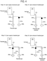
- an opening/closing state of each of the APC valves 244a and 244b is maintained for a predetermined time in the same manner as that illustrated in the upper left side of FIG. 4 .
- the precursor gas remaining in the process chamber 201 is exhausted from the first exhaust system.
- the valves 243c and 243d are kept open to maintain the supply of the inert gas into the process chamber 201.
- the inert gas acts as a purge gas, which promotes the exhaust of the residual gas (precursor gas) from the interior of the process chamber 201, the interior of the exhaust pipe 231, and the interior of the exhaust pipe 231a.
- step 1A the second gas (reactant gas) is supplied to the wafer 200.
- the opening/closing control of the valves 243b and 243d is performed in the same procedure as the opening/closing control of the valves 243a, 243c, and 243d in step 1A to allow the reactant gas to flow through the gas supply pipe 232b.
- the reactant gas is regulated in flow rate by the MFC 241b, is supplied into the process chamber 201 via the nozzle 249b, and is exhausted via the exhaust pipe 231 from the exhaust pipe 231b, i.e., from the second exhaust system. At this time, the reactant gas is supplied to the wafer 200.
- the Si-containing layer formed on the wafer 200 may be modified (nitrided) by supplying the reactant gas to the wafer 200.
- a layer containing Si and N i.e., a silicon nitride layer (SiN layer) is formed on the wafer 200.
- impurities such as Cl contained in the Si-containing layer are separated from this layer in the course of the modification reaction, forming a gaseous substance containing at least Cl to be discharged from the process chamber 201.
- the SiN layer becomes a layer with fewer impurities such as Cl than the Si-containing layer.
- the valve 243b is closed to stop the supply of the reactant gas.
- the opening/closing state of each of the APC valves 244a and 244b is maintained for a predetermined time in the same manner as that illustrated in the lower left side of FIG. 4 .
- the reactant gas remaining in the process chamber 201 is exhausted from the second exhaust system.
- the valves 243c and 243d are kept open, which promotes the exhaust of the residual gas (reactant gas) from the interior of the process chamber 201, the interior of the exhaust pipe 231, and the interior of the exhaust pipe 231b.
- n is an integer of 1 or more
- the precursor gas and the reactant gas flow intermittently and asynchronously a predetermined number of times into the process chamber 201.
- This may form a film (e.g., SiN film) with a predetermined film thickness on the wafer 200.
- the above-described cycle may be performed multiple times.
- the inert gas is supplied into the process chamber 201 from the respective gas supply pipes 232c and 232d, and the interior of the process chamber 201 is vacuum-exhausted by the first exhaust system and the second exhaust system.
- the interior of the process chamber 201 is purged with the inert gas, and the gas and reaction by-products remaining in the process chamber 201 are removed from the interior of the process chamber 201 (after-purge).
- the atmosphere in the process chamber 201 is replaced with the inert gas (inert gas replacement), and the internal pressure of the process chamber 201 is returned to normal pressure (returning to atmospheric pressure).
- the seal cap 219 is lowered by the boat elevator 115 to open the lower end of the reaction tube 203. Then, the processed wafer 200 is unloaded from the lower end of the reaction tube 203 to the outside of the reaction tube 203 while being supported in the boat 217 (boat unloading). The processed wafer 200 is discharged from the boat 217 (wafer discharge).
- the substrate processing apparatus includes the first exhaust system including the exhaust pipe 231a, which is the first exhaust line, and the second exhaust system including the exhaust pipe 231b, which is the second exhaust line. Then, each of the exhaust pipes 231a and 231b is formed with a vacuum pump specification as the first pump. Therefore, even when the precursor gas and the reactant gas are supplied to the wafer 200, each gas may be exhausted separately such that the precursor gas is exhausted from the first exhaust system and the reactant gas is exhausted from the second exhaust system. This makes it possible to reduce an amount of byproducts accumulated in the exhaust system, thereby extending a period until pump maintenance is performed. As a result, it becomes possible to reduce a maintenance frequency of the exhaust system.
- the deterioration in performance of the exhaust system may involve at least one selected from the group of, for example, deterioration in performance of the vacuum pump, deterioration in performance of the valve, and deterioration in performance (conductance) of the exhaust pipe.
- the vacuum pump 246a which is the first pump, is expected to be higher in failure rate than other components due to susceptibility to attachment of by-products, raising concerns about the deterioration in performance of the exhaust system caused by such failures.
- the deterioration in performance of the exhaust system may become a factor that prevents desired film formation in the process chamber 201.
- a decrease in exhaust amount may lead to inability to exhaust the precursor gas before it undergoes decomposition in the process chamber 201, resulting in particle generation in the process chamber 201 and consequent deterioration such as deterioration in coverage.
- the deterioration in performance of the exhaust system may lead to deterioration in characteristics of the film formed on the wafer 200.
- the controller 121 monitors a state of the exhaust system.
- the controller 121 is configured to perform the following control processing.
- the control processing by the controller 121 will be described below.
- the state of the exhaust system may include at least one selected from the group of an opening state of each valve, a pressure of the first exhaust line, a pressure of the second exhaust line, and a state of the pumps 246a and 246b.
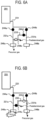
- step 1A in the film formation step of the above-described substrate processing process as illustrated in FIG. 5A , the controller 121 sets the APC valve 244a to an open state (represented by a white circle in the drawing) and the APC valve 244b to a fully closed state (represented by a black circle in the drawing). Further, the controller 121 sets the respective valves 244c and 244d in the bypass line 233 to a fully closed state.
- the precursor gas is exhausted by the first exhaust system via the exhaust pipe 231a as the first exhaust line when operating the vacuum pump 246a.
- the controller 121 monitors whether or not the exhaust pipe 231a as the first exhaust line is in a predetermined state.
- predetermined state refers to a state in which there is a high possibility of a malfunction in the exhaust conducted via the exhaust pipe 231a. Specifically, this may correspond, for example, to at least one state selected from the group of (i) to (v) described below.
- the controller 121 determines that the exhaust pipe 231a transitioned into the predetermined state. Then, when it is detected that the exhaust pipe 231a transitioned into the predetermined state, the controller 121 performs a line change processing of changing a gas flow (hereinafter, referred to as a first line change processing).
- the first line change processing is a processing of exhausting the precursor gas supplied to the wafer 200, toward the vacuum pump 246b via the exhaust pipe 231b as the second exhaust line, rather than the exhaust pipe 231a as the first exhaust line. That is, the first line change processing refers to a processing of switching from the exhaust by the first exhaust system to the exhaust by the second exhaust system.
- the controller 121 controls the operation of each of the APC valve 244a and the APC valve 244b such that the APC valve 244a is in a fully closed state and the APC valve 244b is in an open state. In this operation, the respective valves 244c and 244d in the bypass line 233 are kept in a fully closed state.
- the precursor gas supplied to the wafer 200 is exhausted by the second exhaust system via the exhaust pipe 231b as the second exhaust line when the vacuum pump 246b is in operation.
- the precursor gas may be supplied as a predetermined gas from the bypass line 233 to the exhaust pipe 231a.
- the controller 121 sets the APC valve 244a to a fully closed state (represented by a black circle in the drawing) and the valve 244c in the bypass line 233 to an open state (represented by a white circle in the drawing).
- the controller 121 also sets the APC valve 244b and the valve 244d in the bypass line 233 to a fully closed state.
- the controller 121 sets the valve 248b installed at the pipe 248a connected to the first gas supply line to an open state.
- the precursor gas present in the first gas supply line may be exhausted to the bypass line 233 via the pipe 248a.
- the precursor gas exhausted to the bypass line 233 is exhausted via the exhaust pipe 231a to the pump 246a.
- the controller 121 performs a line change processing (hereinafter, referred to as a second line change processing) of changing the gas flow when it is detected that the exhaust pipe 231a transitioned into the predetermined state in the same manner as the case of normal operation described above.
- the second line change processing is a processing of exhausting the precursor gas in the first gas supply line toward the vacuum pump 246b via the bypass line 233 and the exhaust pipe 231b as the second exhaust line, rather than the exhaust pipe 231a as the first exhaust line. That is, the second line change processing refers to a processing of switching from the exhaust by the first exhaust system to the exhaust by the second exhaust system while using the bypass line 233.
- the controller 121 controls the operation of each of the valve 244c and the valve 244d in the bypass line 233 such that the valve 244c is in a fully closed state and the valve 244d is in an open state. In this operation, the APC valves 244a and 244b are kept in a fully closed state.
- the precursor gas in the first gas supply line is exhausted by the second exhaust system via the bypass line 233 and the exhaust pipe 231b as the second exhaust line when the vacuum pump 246b is in operation.
- the term "the precursor gas changed in characteristics (properties)" as used herein refers to at least one selected from the group of a partially decomposed gas, an agglomerated gas, a gas differing in concentration of a precursor, and a gas differing in pressure.
- the controller 121 controls the opening/closing operation of the APC valves 244a and 244b and the valves 244c and 244d so as to perform the first line change processing while the wafer 200 is being processed in the process chamber 201 and to perform the second line change processing after the first line change processing. That is, when the exhaust pipe 231a transitions into the predetermined state, the precursor gas is exhausted via the exhaust pipe 231b as the second exhaust line during film formation, but during bypass line purging after film formation, the residual gas including the precursor gas is exhausted via the bypass line 233 to the exhaust pipe 231b.
- the abrupt change in the processing environment refers to, for example, a situation where the precursor gas exhausted to the exhaust pipe 231a via the bypass line 233, flows backward toward the process chamber 201 due to certain reasons, or a situation where a precursor gas in an unexpected state enters the exhaust pipe 231a, affecting film formation. Accordingly, processing uniformity for each wafer 200 (for each batch) processed within the process chamber 201 may be improved.
- the substrate processing apparatus may undergo apparatus maintenance (e.g., replacement of pumps, valves, and pipes) at a timing at which the above-described substrate processing process is not being performed.
- apparatus maintenance e.g., replacement of pumps, valves, and pipes
- the residual gas may be exhausted from the exhaust pipe 231a as the first exhaust line before performing the apparatus maintenance.
- the controller 121 performs the following control processing when detecting that the exhaust pipe 231a transitioned into the predetermined state before performing the apparatus maintenance. That is, the controller 121 performs a line change processing of changing the gas flow (hereinafter, referred to as a third line change processing) when the wafer 200 is not being processed within the process chamber 201.
- the third line change processing is a processing of exhausting the atmosphere in the exhaust pipe 231a as the first exhaust line via the bypass line 233 from the exhaust pipe 231b as the second exhaust line.
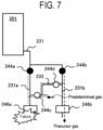
- the controller 121 controls the operation of each of the valves 244c and 244d in the bypass line 233 such that the valves 244c and 244d are in an open state, as illustrated in FIG. 7 , at a timing before the apparatus maintenance at which the wafer 200 is not being processed within the process chamber 201.
- the APC valves 244a and 244b are in a closed state. That is, in the third line change processing, both the APC valves 244a and 244b are substantially in a closed state, whereas the respective valves 244c and 244d in the bypass line 233 are in an open state.
- the exhaust pipe 231a transitioned into the predetermined state before the apparatus maintenance, it becomes possible to exhaust the atmosphere in the exhaust pipe 231a (for example, the residual precursor gas) via the bypass line 233 and the exhaust pipe 231b without passing through the process chamber 201 by switching the exhaust path.
- the atmosphere in the exhaust pipe 231a for example, the residual precursor gas
- the above-described first line change processing, second line change processing, and third line change processing are performed in response to the transition of the exhaust pipe into the predetermined state. Therefore, the controller 121 monitors the state of the exhaust pipe 231a and determines whether the exhaust pipe 231a transitioned into the predetermined state. Such a determination may be performed depending on whether or not at least one selected from the group of (i) to (v) is satisfied as described above, but the determination may be performed as described below.
- the controller 121 when determining the state of the exhaust pipe 231a, the controller 121 supplies an inert gas into the process chamber 201 via the gas supply pipes 232c and 232d as the inert gas supply lines constituting the inert gas supply system. Then, the pressure state in the exhaust pipe when the inert gas is exhausted via the exhaust pipe 231a, which is the first exhaust line, is detected. As a result, in a case where the pressure state in the exhaust pipe 231a is out of a predefined normal state, it is determined that the exhaust pipe transitioned into the predetermined state.
- the internal pressure of the exhaust pipe 231a is measured by either or both of the pressure gauge 245 and the first pressure gauge 247a.
- the controller 121 determines, based on the supply of the inert gas from the inert gas supply line, whether the exhaust pipe 231a transitioned into the predetermined state. As such, in a case where the determination is made by using the supply of the inert gas, the first line change processing and the like are not performed during the supply of a process gas such as the precursor gas or the reactant gas, and as a result, unintentional film formation may be avoided.
- the controller 121 may determine, before the supply of the first gas (precursor gas), whether the exhaust pipe 231a transitioned into the predetermined state.
- "Before the supply of the precursor gas” includes, for example, "before the start of the film formation step in the substrate processing process” and "before the supply of the precursor gas while performing one or more cycles.” As such, in a case where the determination is performed before the supply of the precursor gas, the first line change processing and the like are not performed during the supply of the precursor gas, and as a result, unintentional film formation may be avoided.
- the controller 121 may determine, between the supply of the first gas (precursor gas) and the supply of the second gas (reactant gas), whether the exhaust pipe 231a transitioned into the predetermined state. As such, in a case where the determination is performed between the supply of the precursor gas and the supply of the reactant gas, the first line change processing and the like are not performed during the supply of the reactant gas, and as a result, unintentional film formation may be avoided.
- the controller 121 may determine, after the supply of the second gas (reactant gas), whether the exhaust pipe 231a transitioned into the predetermined state.
- “After the supply of the reactant gas” includes, for example, “after completion of the film formation step in the substrate processing process” and “after the supply of the reactant gas while performing one or more cycles (before the supply of the precursor gas).”
- the determination is performed after the supply of the reactant gas, the first line change processing and the like are not performed during the supply of the reactant gas, and as a result, unintentional film formation may be avoided. Further, making the determination after film formation enables determination of whether film formation may be performed on the next wafer 200. Further, in a case where the determination is made during the cycle, it becomes possible to easily grasp that the line change processing was performed in the N th cycle.
- the controller 121 performs the first line change processing and the like when detecting that the exhaust pipe 231a transitioned into the predetermined state. At that time, the controller 121 may issue an alarm notification. That is, the controller 121 may issue an alarm notification when detecting that the exhaust pipe 231a transitioned into the predetermined state.
- the alarm notification may be made by, for example, sound output which uses a speaker, display output of light which uses a lighting, display output of characters, images, and the like which use a display screen, and output of an alarm signal to a host apparatus and the like which uses a communication line, as long as such an output may notify state transition.
- a user of the substrate processing apparatus which is an alarm notification target may easily and accurately recognize, for example, that substrate processing process is being performed under a condition different from a desired condition, or that the substrate processing apparatus is in an abnormal state.
- the controller 121 may continue an ongoing processing on the wafer 200 in the process chamber 201 after issuing the alarm notification until the processing is completed. Furthermore, the controller 121 may not initiate a next substrate processing after the processing on the wafer 200 in the process chamber 201 is completed. That is, based on the alarm notification, the controller 121 completes the ongoing processing but does not initiate a new processing, and may set a hold state in which the substrate processing apparatus is stopped before the start of a recipe.
- the substrate processing apparatus may be stopped without initiating a next new processing, thereby preventing a substrate processing under a condition different from a desired condition in advance.
- the controller 121 may be configured to be capable of transmitting information on the wafer 200 processed after the alarm notification is issued, as well as information indicating that the alarm notification was issued, to a host apparatus by using a communication line.
- the controller 121 may be configured to be capable of transmitting information on the wafer 200 processed after the alarm notification is issued, as well as information indicating that the alarm notification was issued, to a host apparatus by using a communication line.
- controller 121 may not transmit both of the alarm notification information and the information on the wafer 200, and may be configured to transmit at least one selected from the group of the alarm notification information and the information on the wafer 200 to the host apparatus. Even in this case, the host apparatus may obtain useful information in understanding the state of the substrate processing apparatus or the processed wafer 200.
- the controller 121 may detect whether the exhaust pipe 231b transitioned into the predetermined state, and may perform control to switch the exhaust system based on the detected result.
- a gas containing oxygen is added as the reactant gas, which is the second gas.
- oxidizing agent in addition to a H 2 O gas, an O-containing gas containing O-H bonds such as a hydrogen peroxide (H 2 O 2 ) gas, or an O-containing gas containing O-O bonds without containing O-H bonds such as oxygen (O 2 ) gas, ozone (O 3 ) gas, hydrogen (H 2 ) gas+O 2 gas, and H 2 gas+O 3 gas may be used.
- a gas containing carbon or catalyst is added as the reactant gas, which is the second gas.
- the above-described embodiments described the example where a batch-type substrate processing apparatus configured to process a plurality of substrates at once is used, but the present disclosure is not limited thereto, and is also suitably applicable to, for example, a single-wafer-type substrate processing apparatus configured to process one or several substrates at once. Further, the above-described embodiments describe the example where a substrate processing apparatus including a hot-wall-type process furnace is used, but the present disclosure is not limited thereto, and is also suitably applicable to, for example, a substrate processing apparatus including a cold-wall-type process furnace.
Landscapes
- Chemical & Material Sciences (AREA)
- Chemical Kinetics & Catalysis (AREA)
- General Chemical & Material Sciences (AREA)
- Engineering & Computer Science (AREA)
- Materials Engineering (AREA)
- Mechanical Engineering (AREA)
- Metallurgy (AREA)
- Organic Chemistry (AREA)
- Inorganic Chemistry (AREA)
- Chemical Vapour Deposition (AREA)
- Cleaning Or Drying Semiconductors (AREA)
- Drying Of Semiconductors (AREA)
Abstract
Description
- The present disclosure relates to a substrate processing apparatus, a method of processing a substrate, a method of manufacturing a semiconductor device, a program, and an exhaust system.
- As a substrate processing apparatus which is used in a process of manufacturing a semiconductor device, for example, there is a substrate processing apparatus that includes: a first exhaust system configured to exhaust a precursor from an interior of a process chamber; and a second exhaust system configured to exhaust a reactant from the interior of the process chamber, and is configured to reduce a maintenance frequency of the exhaust systems (for example, see Patent Document 1).
- Patent Document 1:
Japanese laid-open publication No. 2019-186574 - The present disclosure provides a technique capable of preventing characteristic deterioration of process results even in a case where a desired process condition may not be obtained depending on a state of an exhaust system.
- According to embodiments of the present disclosure, there is provided a technique including a first gas supply line configured to supply a first gas to a substrate in a process chamber, a first exhaust line connected to a first pump and configured to exhaust the first gas supplied to the substrate, a first valve installed at the first exhaust line, a second gas supply line configured to supply a second gas to the substrate in the process chamber, a second exhaust line connected to a second pump and configured to exhaust the second gas supplied to the substrate, a second valve installed at the second exhaust line, and a controller configured to be capable of controlling the first valve and the second valve, so as to perform a first line change processing of exhausting the first gas supplied to the substrate toward the second pump via the second exhaust line, when detecting that the first exhaust line transitioned into a predetermined state.
- According to the present disclosure, it is possible to establish an atmosphere close to a desired process condition even when an exhaust system transitions into a predetermined state, thereby preventing characteristic deterioration of process results.
-
-
FIG. 1 is a longitudinal cross-sectional view illustrating a process furnace of a substrate processing apparatus according to some embodiments of the present disclosure. -
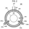
FIG. 2 is a cross-sectional view illustrating the process furnace of the substrate processing apparatus according to the embodiments of the present disclosure, and is a view of a cross section taken along line A-A ofFIG. 1 . -
FIG. 3 is a block diagram illustrating a controller of a substrate processing apparatus according to the embodiments of the present disclosure. -
FIG. 4 is an explanatory diagram illustrating a process operation of an exhaust system of a substrate processing apparatus according to the embodiments of the present disclosure. -
FIGS. 5A and 5B are explanatory diagrams illustrating a process operation of switching an exhaust system during film formation of a substrate processing apparatus according to the embodiments of the present disclosure,FIG. 5A is a diagram illustrating a normal operating state, andFIG. 5B is a diagram illustrating a state after transition into a predetermined state. -
FIGS. 6A and 6B are explanatory diagrams illustrating a process operation of switching an exhaust system while using a bypass line of a substrate processing apparatus according to the embodiments of the present disclosure,FIG. 6A is a diagram illustrating a normal operating state, andFIG. 6B is a diagram illustrating a state after transition into a predetermined state. -
FIG. 7 is an explanatory diagram illustrating a process operation of switching an exhaust system before maintenance of a substrate processing apparatus according to the embodiments of the present disclosure. - Hereinafter, some embodiments of the present disclosure will be described with reference to the accompanying drawings. In addition, the drawings used in the following description are schematic and dimensional relationships, proportions, and the like of the respective components in the drawing may not correspond to actual ones. Further, dimensional relationships, proportions, and the like of the respective components may not correspond to one another among multiple drawings.
- First, a configuration of a substrate processing apparatus according to embodiments of the present disclosure will be described.
- Here, an example of a substrate processing apparatus will be described, which is used in a process of manufacturing a semiconductor device, and is a vertical batch-type apparatus configured to perform a film formation and the like on a plurality of substrates at once.
- As illustrated in
FIG. 1 , a substrate processing apparatus according to the embodiments of the present disclosure is configured to include aprocess furnace 202. - The
process furnace 202 includes aheater 207 as a heating means or unit (heating mechanism). Theheater 207 is formed in a cylindrical shape and is mounted vertically by being supported by a holding plate. Theheater 207 also functions as an activator (exciter) configured to activate (excite) a gas with heat. - A
reaction tube 203 is disposed inside theheater 207 to be concentric with theheater 207 so as to configure a reaction container (process container). Thereaction tube 203 is made of, for example, a heat-resistant material such as quartz (SiO2) or silicon carbide (SiC) and is formed in a cylindrical shape with its upper end closed and lower end opened. - A
process chamber 201 is formed in a tubular hollow area of thereaction tube 203. Theprocess chamber 201 is configured to be capable of accommodating awafer 200 as a substrate. - A
seal cap 219, which serves as a furnace opening lid configured to be capable of airtightly sealing a lower end opening of thereaction tube 203, is installed under thereaction tube 203. Theseal cap 219 is made of, for example, a metal such as SUS, and is formed in a disc shape. An O-ring 220, which is a seal making contact with the lower end of thereaction tube 203, is installed on an upper surface of theseal cap 219. Arotator 267 configured to rotate aboat 217 to be described later is installed below theseal cap 219. Arotary shaft 255 of therotator 267 is connected to theboat 217 through theseal cap 219. Therotator 267 is configured to rotate thewafer 200 by rotating theboat 217. Theseal cap 219 is configured to be moved up or down vertically by aboat elevator 115 as an elevator installed outside thereaction tube 203. Theboat elevator 115 is configured as a transfer apparatus (transfer mechanism) configured to load or unload (transfer) theboat 217, i.e., thewafer 200 into or out of theprocess chamber 201 by moving theseal cap 219 up or down. - The
boat 217 serving as a substrate support is configured to support a plurality of (e.g., 25 to 200) wafers 200 in such a state that thewafers 200 are arranged in a horizontal posture and in multiple stages along a vertical direction with centers of thewafers 200 aligned with one another. That is, theboat 217 is configured to arrange thewafers 200 in a spaced-apart relationship. Theboat 217 is made of, for example, a heat-resistant material such as quartz or SiC.Heat insulating plates 218 made of, for example, a heat-resistant material such as quartz or SiC are supported in a horizontal posture and in multiple stages below theboat 217. - A
temperature sensor 263 as a temperature detector is installed inside thereaction tube 203. By regulating a state of supplying electric power to theheater 207 based on temperature information detected by thetemperature sensor 263, an internal temperature of theprocess chamber 201 falls within a desired temperature distribution. Thetemperature sensor 263 is installed along an inner wall of thereaction tube 203. -
Nozzles process chamber 201 so as to penetrate a lower sidewall of thereaction tube 203.Gas supply pipes nozzles - At the
gas supply pipes valves Gas supply pipes 232c and 232d configured to supply an inert gas are connected to thegas supply pipes valves gas supply pipes 232c and 232d,MFCs 241c and 241d andvalves - As illustrated in
FIG. 2 , thenozzles reaction tube 203 and thewafers 200 to extend upward from a lower side to an upper side of the inner wall of thereaction tube 203, that is, along an arrangement direction of thewafers 200. That is, thenozzles wafers 200 are arranged at a lateral side of the wafer arrangement region, along the wafer arrangement region.Gas supply holes nozzles gas supply holes reaction tube 203, thus enabling the gas to be supplied toward thewafers 200. Thesegas supply holes reaction tube 203. - As a precursor gas which is a first gas, a halogen-based precursor gas containing a predetermined element (main element) and a halogen element is suppled from the
gas supply pipe 232a into theprocess chamber 201 via theMFC 241a, thevalve 243a, and thenozzle 249a. That is, thegas supply pipe 232a functions as a first gas supply line configured to supply the precursor gas, which is the first gas, to thewafers 200 in theprocess chamber 201. - The precursor gas is a gaseous precursor, for example, a gas obtained by vaporizing a precursor, which is in a liquid phase under normal temperature and normal pressure, or a precursor which is in a gas phase under normal temperature and normal pressure. Examples of the halogen element may include chlorine (Cl), fluorine (F), bromine (Br), and iodine (I). That is, the halogen-based precursor gas contains halogen groups such as chloro groups, fluoro groups, bromo groups, and iodine groups. As the halogen-based precursor gas, for example, a halosilane precursor gas containing silicon (Si) and Cl as the predetermined element, i.e., a chlorosilane precursor gas may be used. For example, a hexachlorodisilane (Si2C6, abbreviation: HCDS) gas may be used as the chlorosilane precursor gas. Further, in addition to the HCDS gas, a chlorosilane precursor gas containing Si-Cl bonds, such as a monochlorosilane (SiH3Cl, abbreviation: MCS) gas, dichlorosilane (SiH2Cl2, abbreviation: DCS) gas, trichlorosilane (SiHCl3, abbreviation: TCS) gas, tetrachlorosilane (SiCl4, abbreviation: STC) gas, and octachlorotrisilane (Si3Cl8, abbreviation: OCTS) gas, may be used as the precursor gas.
- That is, the precursor gas, which is the first gas, is a gas containing a main constituent element (e.g., Si) constituting a film (e.g., Si-containing film) to be formed on the
wafer 200. Specifically, the precursor gas, which is the first gas, is, for example, a Si-containing gas. More specifically, the precursor gas, which is the first gas, is, for example, a halosilane-based gas such as a chlorosilane-based gas. - A precursor supply system (halosilane precursor supply system) mainly includes the
gas supply pipe 232a, theMFC 241a, and thevalve 243a. - As a reactant gas which is a second gas, a gas containing nitrogen (N) (nitriding gas or nitriding agent) is supplied from the
gas supply pipe 232b into theprocess chamber 201 via theMFC 241b, thevalve 243b, and thenozzle 249b. That is, thegas supply pipe 232b functions as a second gas supply line configured to supply the reactant gas, which is the second gas, to thewafers 200 in theprocess chamber 201. - For example, a hydrogen nitride-based gas such as an ammonia (NH3) gas may be used as the nitriding agent constituting the reactant gas. Further, in addition to the NH3 gas, a hydrogen nitride-based gas containing N-H bonds such as a diazene (N2H2) gas, hydrazine (N2H4) gas, and N3H8 gas may be used as the reactant gas.
- That is, the reactant gas, which is the second gas, is a gas not containing the main constituent element (e.g., Si) constituting the film (e.g., Si-containing film) to be formed on the
wafer 200. Specifically, the reactant gas, which is the second gas, includes, for example, at least one selected from the group of a C-containing gas such as C3H6, an O-containing gas such as O2, and a N- and H-containing gas. Further, the reactant gas, which is the second gas, may include, for example, the C-containing gas, the O-containing gas, and the N- and H-containing gas. - A reactant supply system (nitriding agent supply system) mainly includes the
gas supply pipe 232b, theMFC 241b, and thevalve 243b. - An inert gas is supplied from the respective
gas supply pipes 232c and 232d into theprocess chamber 201 via the MFCs 241c and 3241d, thevalves gas supply pipes nozzles gas supply pipes 232c and 232d function as inert gas supply lines configured to supply the inert gas into theprocess chamber 201. - As the inert gas, for example, at least one or more selected from the group of a nitrogen (N2) gas, helium (He) gas, neon (Ne) gas, argon (Ar) gas, and xenon (Xe) gas may be used.
- An inert gas supply system mainly includes the
gas supply pipes 232c and 232d, the MFCs 241c and 241d, and thevalves - The
reaction tube 203 is provided with anexhaust pipe 231 configured to exhaust the atmosphere in theprocess chamber 201. Apressure sensor 245 as a pressure detector (pressure detection part) configured to detect the internal pressure of theprocess chamber 201 is installed at the upstream side of theexhaust pipe 231. The downstream side of theexhaust pipe 231 is branched intoexhaust pipes - As illustrated by oblique lines in
FIG. 1 , for example, a ribbon-shapedheater 231h is wound around an outer periphery of theexhaust pipe 231 and outer peripheries of upstream sides of theexhaust pipes - The
exhaust pipe 231a is connected to avacuum pump 246a as a first vacuum exhauster. Then, by operating thevacuum pump 246a, theexhaust pipe 231a functions as a first exhaust line configured to exhaust the precursor gas, which is the first gas, in theprocess chamber 201 via theexhaust pipe 231. - At the
exhaust pipe 231a, an auto pressure controller (APC)valve 244a as a pressure regulator (pressure regulation part) is installed. TheAPC valve 244a functions as a first valve installed at the first exhaust line. By opening or closing the valve while thevacuum pump 246a is in operation, a vacuum exhaust of the interior of theprocess chamber 201 may be performed or stopped. Further, the internal pressure of theprocess chamber 201 may be regulated by adjusting an opening state of the valve based on pressure information detected by thepressure sensor 245 while thevacuum pump 246a is in operation. - A first exhaust system mainly includes the
exhaust pipe 231, theexhaust pipe 231a, and theAPC valve 244a. Thevacuum pump 246a may be included in the first exhaust line. - Further, a first pressure gauge 247a may be installed at the
exhaust pipe 231 on the rear end of theAPC valve 244a (near thevacuum pump 246a). In this case, the first pressure gauge 247a may be included in the first exhaust line. - The
exhaust pipe 231b is connected to avacuum pump 246b as a second vacuum exhauster. Then, by operating thevacuum pump 246b, theexhaust pipe 231b is configured to exhaust the reactant gas supplied to thewafers 200 in theprocess chamber 201, via theexhaust pipe 231. That is, theexhaust pipe 231b functions as a second exhaust line configured to exhaust the reactant gas, which is the second gas. - At the
exhaust pipe 231b, anAPC valve 244b as a pressure regulator (pressure regulation part) is installed. TheAPC valve 244b functions as a second valve installed at the second exhaust line. By opening or closing the valve while thevacuum pump 246b is in operation, the vacuum exhaust of the interior of theprocess chamber 201 may be performed or stopped. Furthermore, the internal pressure of theprocess chamber 201 may be regulated by adjusting an opening degree of the valve based on pressure information detected by thepressure sensor 245 while thevacuum pumps - A second exhaust system mainly includes the
exhaust pipe 231, theexhaust pipe 231b, and theAPC valve 244b. Thevacuum pump 246b may be included in the second exhaust line. - Further, a second pressure gauge 247b may be installed at the
exhaust pipe 231b on the rear end of theAPC valve 244b (near thevacuum pump 246b). In this case, the second pressure gauge 247b may be included in the second exhaust line. - Either or both of the first exhaust system and the second exhaust system may be referred to as an exhaust system. The
pressure sensor 245 and theheater 231h may be included in the exhaust system. - In addition, the first exhaust system and the second exhaust system are alternately switched and used. That is, the first exhaust system is used when exhausting the atmosphere containing the precursor from the
process chamber 201, whereas the second exhaust system is used when exhausting the atmosphere containing the reactant from theprocess chamber 201. - A
bypass line 233 is installed at theexhaust pipe 231a on the downstream side of theAPC valve 244a and at theexhaust pipe 231b on the downstream side of theAPC valve 244b to interconnect theexhaust pipes bypass line 233 is connected to theexhaust pipe 231a via avalve 244c as a third valve, and is connected to theexhaust pipe 231b via avalve 244d as a fourth valve. - A branching point is provided between the
valves bypass line 233. Then, the branched end is connected to a gas source (not illustrated) via avalve 248b installed at apipe 248a connected to thegas supply pipe 232a, such that a predetermined gas (herein, precursor gas) is supplied to thebypass line 233. - The substrate processing apparatus according to the embodiments of the present disclosure is configured to include a
controller 121 as a control part (control means or unit). - As illustrated in
FIG. 3 , thecontroller 121 is configured as a computer including a central processing unit (CPU) 121a, a random access memory (RAM) 121b, amemory 121c, and I/O port 121d. TheRAM 121b,memory 121c, and I/O port 121d are configured to be capable of exchanging data with theCPU 121a via aninternal bus 121e. An input/output device 122, which is configured as, for example, a touch panel, is connected to thecontroller 121. - The
memory 121c includes, for example, a flash memory and a hard disk drive (HDD). Thememory 121c stores, in a readable manner, a control program that controls the operation of the substrate processing apparatus, a process recipe describing procedures, conditions and the like of a substrate processing process, which will be described later, and the like. The process recipe functions as a program configured to be capable of causing thecontroller 121 to execute each procedure in the substrate processing process, which will be described later, to obtain a predetermined result. Hereinafter, the process recipe, the control program, and the like may be generally and simply referred to as a "program." Further, the process recipe is simply referred to as a recipe. When the term "program" is used herein, it may refer to the recipe, the control program, or both of them. TheRAM 121b is configured as a memory area (work area) in which programs, data, and the like read by theCPU 121a are temporarily held. - The I/
O port 121d is connected to, for example, the above-describedMFCs 241a to 241h,valves 243a to 243h, 244c and 244d,pressure sensor 245,APC valves vacuum pumps heaters temperature sensor 263,rotator 267,boat elevator 115. - The
CPU 121a is configured to read and execute the control program from thememory 121c and to read the recipe from thememory 121c, for example, when an operation command is input from the input/output device 122. TheCPU 121a is configured to be capable of controlling the flow rate regulating operation of various gases by theMFCs 241a to 241h, the opening/closing operation of thevalves 243a to 243h, 244c, 244d, and 248b, the opening/closing operation of theAPC valves APC valves pressure sensor 245, the actuating and stopping operation of thevacuum pumps heater 207 based on thetemperature sensor 263, the temperature regulating operation of theheater 231h, the operation of rotating theboat 217 and adjusting the rotational speed of theboat 217 by therotator 267, and the operation of moving theboat 217 up or down by theboat elevator 115, and so on, according to contents of the read recipe. - The
controller 121 may be configured by installing, on the computer, the above-described program stored in an external memory (e.g., a magnetic disk such as a hard disk, an optical disc such as a CD, a magneto-optical disc such as an MO, and a semiconductor memory such as a USB memory) 123. Thememory 121c or theexternal memory 123 is configured as a computer-readable recording medium. Hereinafter, thememory 121c and theexternal memory 123 are collectively referred to simply as a recording medium. When the term "recording medium" is used herein, it may refer to thememory 121c, theexternal memory 123, or both of them. In addition, the program may be provided to the computer by using a communicator such as the Internet or a dedicated line without using theexternal memory 123. - The substrate processing apparatus configured as described above constitutes an exhaust system, together with the
vacuum pumps vacuum pump 246a as the first pump, and thevacuum pump 246b as the second pump. - Next, as a process of manufacturing a semiconductor device, a procedure of forming a silicon nitride film (SiN film) on the
wafer 200 as a substrate by using the substrate processing apparatus with the above-described configuration will be described. In the following description, an operation of each component of the substrate processing apparatus is controlled by thecontroller 121. - In addition, when the term "wafer" is used herein, it may refer to "a wafer itself," or "a stacked body (assembly) of a wafer and a certain layer or film formed on a surface of the wafer," i.e., "a wafer including a certain layer or film formed on the surface thereof." Further, when the term "a surface of a wafer" is used herein, it may refer to "a surface (exposed surface) of a wafer itself," or "a surface of a certain layer or film formed on the wafer," i.e., "an outermost surface of a wafer as a stacked body."
- Accordingly, when it is stated herein "supplying a predetermined gas to a wafer," it may refer to "directly supplying a predetermined gas to a surface (exposed surface) of a wafer itself," or "supplying a predetermined gas to a layer or film formed on a wafer, i.e., to an outermost surface of a wafer as a stacked body." Further, when it is stated herein "forming a certain layer (or film) on a wafer," it may refer to "directly forming a certain layer (or film) on a surface (exposed surface) of a wafer itself," or "forming a certain layer (or film) on a layer or film formed on a wafer, i.e., on an outermost surface of a wafer as a stacked body."
- Further, the term "substrate" is used herein, it may be synonymous with the term "wafer." In such a case, the "wafer" may be replaced with the "substrate" in the above description.
- Hereinafter, the substrate processing process will be described.
- The
boat 217 is charged with a plurality of wafers 200 (wafer charging). Thereafter, theboat 217 supporting the plurality ofwafers 200 is lifted by theboat elevator 115 and is loaded into the process chamber 201 (boat loading). In this state, theseal cap 219 seals the lower end of thereaction tube 203 via the O-ring 220. - The interior of the
process chamber 201, that is, a space where thewafers 200 are placed, is vacuum-exhausted (decompression-exhausted) by the first exhaust system and the second exhaust system such that an internal pressure (state of vacuum) of theprocess chamber 201 reaches a desired pressure (state of vacuum). At this time, the internal pressure of theprocess chamber 201 is measured by thepressure sensor 245, and theAPC valves vacuum pumps wafers 200 is completed. - Further, the
heater 207 heats thewafers 200 in theprocess chamber 201 such that thewafers 200 reach a predetermined temperature (film formation temperature). At this time, a state of supplying electric power to theheater 207 is feedback-controlled based on the temperature information detected by thetemperature sensor 263 such that a temperature distribution in theprocess chamber 201 becomes a predetermined temperature distribution. Further, theheater 231h is used to heat theexhaust pipe 231 and theexhaust pipes APC valves exhaust pipe 231 and the interiors of theexhaust pipes heaters wafers 200 is completed. - Further, the rotation of the
boat 217 and thewafers 200 by therotator 267 is initiated.
The rotation of theboat 217 and thewafers 200 continues at least until the processing on thewafers 200 is completed. - Thereafter, the following
steps 1A and 2A are sequentially performed as a film formation step. - In this step, the first gas (precursor gas) is supplied to the
wafer 200. Specifically, in a state in which theAPC valve 244b is fully closed and theAPC valve 244a is open as illustrated in the upper left side ofFIG. 4 , thevalve 243a is opened to allow the precursor gas to flow through thegas supply pipe 232a. The precursor gas is regulated in flow rate by theMFC 241a, is supplied into theprocess chamber 201 via thenozzle 249a, and is exhausted via theexhaust pipe 231 from theexhaust pipe 231a, i.e., from the first exhaust system. At this time, the precursor gas is supplied to thewafer 200. At the same time, thevalve 243c is opened to allow the inert gas to flow through thegas supply pipe 232c. The inert gas is supplied into theprocess chamber 201 together with the precursor gas, and is exhausted from theexhaust pipe 231a. Further, to prevent the precursor gas from infiltrating into thenozzle 249b, thevalve 243d is opened to allow the inert gas to flow through the gas supply pipe 232d. The inert gas is supplied into theprocess chamber 201 via thegas supply pipe 232b and thenozzle 249b, and is exhausted from theexhaust pipe 231a. - Here, when a chlorosilane gas is used as the precursor gas, a Si-containing layer containing Cl is formed on the outermost surface of the
wafer 200 by supplying the precursor gas to thewafer 200. The Si-containing layer containing Cl may be a Si layer containing Cl, may be an adsorption layer of precursor gas molecules, or may include both of them. Hereinafter, the Si-containing layer containing Cl is also simply referred to as the Si-containing layer. - Once the Si-containing layer is formed on the
wafer 200, thevalve 243a is closed to stop the supply of the precursor gas. At this time, as illustrated in the upper right side ofFIG. 4 , an opening/closing state of each of theAPC valves FIG. 4 . Thus, the precursor gas remaining in theprocess chamber 201 is exhausted from the first exhaust system. At this time, thevalves process chamber 201. The inert gas acts as a purge gas, which promotes the exhaust of the residual gas (precursor gas) from the interior of theprocess chamber 201, the interior of theexhaust pipe 231, and the interior of theexhaust pipe 231a. - After
step 1A is completed, the second gas (reactant gas) is supplied to thewafer 200. In this step, in a state in which theAPC valve 244a is fully closed and theAPC valve 244b is open as illustrated in the lower left side ofFIG. 4 , the opening/closing control of thevalves valves step 1A to allow the reactant gas to flow through thegas supply pipe 232b. The reactant gas is regulated in flow rate by theMFC 241b, is supplied into theprocess chamber 201 via thenozzle 249b, and is exhausted via theexhaust pipe 231 from theexhaust pipe 231b, i.e., from the second exhaust system. At this time, the reactant gas is supplied to thewafer 200. - Here, when a NH3 gas is used as the reactant gas, at least a part of the Si-containing layer formed on the
wafer 200 may be modified (nitrided) by supplying the reactant gas to thewafer 200. Thus, a layer containing Si and N, i.e., a silicon nitride layer (SiN layer) is formed on thewafer 200. When forming the SiN layer, impurities such as Cl contained in the Si-containing layer are separated from this layer in the course of the modification reaction, forming a gaseous substance containing at least Cl to be discharged from theprocess chamber 201. Thus, the SiN layer becomes a layer with fewer impurities such as Cl than the Si-containing layer. - Once the SiN layer is formed on the
wafer 200, thevalve 243b is closed to stop the supply of the reactant gas. At this time, as illustrated in the lower right side ofFIG. 4 , the opening/closing state of each of theAPC valves FIG. 4 . Thus, the reactant gas remaining in theprocess chamber 201 is exhausted from the second exhaust system. At this time, thevalves process chamber 201, the interior of theexhaust pipe 231, and the interior of theexhaust pipe 231b. - By performing a cycle of alternately performing the above-described
steps 1A and 2A a predetermined number of times n (n is an integer of 1 or more), the precursor gas and the reactant gas flow intermittently and asynchronously a predetermined number of times into theprocess chamber 201. This may form a film (e.g., SiN film) with a predetermined film thickness on thewafer 200. The above-described cycle may be performed multiple times. - After the formation of the SiN film on the
wafer 200 is completed, the inert gas is supplied into theprocess chamber 201 from the respectivegas supply pipes 232c and 232d, and the interior of theprocess chamber 201 is vacuum-exhausted by the first exhaust system and the second exhaust system. Thus, the interior of theprocess chamber 201 is purged with the inert gas, and the gas and reaction by-products remaining in theprocess chamber 201 are removed from the interior of the process chamber 201 (after-purge). Thereafter, the atmosphere in theprocess chamber 201 is replaced with the inert gas (inert gas replacement), and the internal pressure of theprocess chamber 201 is returned to normal pressure (returning to atmospheric pressure). - The
seal cap 219 is lowered by theboat elevator 115 to open the lower end of thereaction tube 203. Then, the processedwafer 200 is unloaded from the lower end of thereaction tube 203 to the outside of thereaction tube 203 while being supported in the boat 217 (boat unloading). The processedwafer 200 is discharged from the boat 217 (wafer discharge). - As described above, in the substrate processing process, the first gas (precursor gas) and the second gas (reactant gas) are supplied to the
wafer 200 in theprocess chamber 201 to form a desired layer (e.g., SiN layer) on thewafer 200. In that case, the substrate processing apparatus includes the first exhaust system including theexhaust pipe 231a, which is the first exhaust line, and the second exhaust system including theexhaust pipe 231b, which is the second exhaust line. Then, each of theexhaust pipes wafer 200, each gas may be exhausted separately such that the precursor gas is exhausted from the first exhaust system and the reactant gas is exhausted from the second exhaust system.
This makes it possible to reduce an amount of byproducts accumulated in the exhaust system, thereby extending a period until pump maintenance is performed. As a result, it becomes possible to reduce a maintenance frequency of the exhaust system. - However, even in the case of a dual pump specification, when operating the substrate processing apparatus for a long period of time, issues such as accumulation of by-products may occur, leading to deterioration in performance of the exhaust system including the exhaust line. The deterioration in performance of the exhaust system may involve at least one selected from the group of, for example, deterioration in performance of the vacuum pump, deterioration in performance of the valve, and deterioration in performance (conductance) of the exhaust pipe. In particular, the
vacuum pump 246a, which is the first pump, is expected to be higher in failure rate than other components due to susceptibility to attachment of by-products, raising concerns about the deterioration in performance of the exhaust system caused by such failures. - The deterioration in performance of the exhaust system may become a factor that prevents desired film formation in the
process chamber 201. Specifically, for example, a decrease in exhaust amount may lead to inability to exhaust the precursor gas before it undergoes decomposition in theprocess chamber 201, resulting in particle generation in theprocess chamber 201 and consequent deterioration such as deterioration in coverage. In other words, the deterioration in performance of the exhaust system may lead to deterioration in characteristics of the film formed on thewafer 200. - Therefore, in the substrate processing apparatus according to the embodiments of the present disclosure, the
controller 121 monitors a state of the exhaust system. When the exhaust system transitions into a predetermined state, thecontroller 121 is configured to perform the following control processing. The control processing by thecontroller 121 will be described below. Here, the state of the exhaust system may include at least one selected from the group of an opening state of each valve, a pressure of the first exhaust line, a pressure of the second exhaust line, and a state of thepumps - In
step 1A in the film formation step of the above-described substrate processing process, as illustrated inFIG. 5A , thecontroller 121 sets theAPC valve 244a to an open state (represented by a white circle in the drawing) and theAPC valve 244b to a fully closed state (represented by a black circle in the drawing). Further, thecontroller 121 sets therespective valves bypass line 233 to a fully closed state. Thus, the precursor gas is exhausted by the first exhaust system via theexhaust pipe 231a as the first exhaust line when operating thevacuum pump 246a. - In this operation, the
controller 121 monitors whether or not theexhaust pipe 231a as the first exhaust line is in a predetermined state. The term "predetermined state" as used herein refers to a state in which there is a high possibility of a malfunction in the exhaust conducted via theexhaust pipe 231a. Specifically, this may correspond, for example, to at least one state selected from the group of (i) to (v) described below. - (i) In a case where there is a decrease in exhaust amount regarding the exhaust conducted via the
exhaust pipe 231a, thecontroller 121 determines that theexhaust pipe 231a transitioned into the predetermined state. Whether or not there is a decrease in exhaust amount may be determined, for example, by detecting a time until a power indicated by either or both of thepressure gauge 245 and the first pressure gauge 247a reaches a predetermined pressure based on a predefined pressure-time curve at the time of the exhaust, or by detecting that the pressure does not fall within a predetermined pressure range within a designated time. In addition, the pressure is measured by using either or both of thepressure gauge 245 and the first pressure gauge 247a duringstep 1A. In a case other thanstep 1A, the pressure is measured by using the first pressure gauge 247a. - (ii) In a case where the
vacuum pump 246a connected to theexhaust pipe 231a experiences sudden stoppage, thecontroller 121 determines that theexhaust pipe 231a transitioned into the predetermined state. Whether or not there is a sudden stoppage of thevacuum pump 246a may be determined, for example, by thecontroller 121 monitoring an operating state of thevacuum pump 246a and detecting an alarm signal and the like from thevacuum pump 246a. - (iii) In a case where a load of the
vacuum pump 246a connected to theexhaust pipe 231a increases, thecontroller 121 determines that theexhaust pipe 231a transitioned into the predetermined state. Whether or not the load of thevacuum pump 246a is increased may be determined, for example, by monitoring a load current value of thevacuum pump 246a and comparing the load current value with a predetermined threshold value since the load current value also increases when the load increases. - (iv) In a case where there is a valve opening malfunction of the
APC valve 244a installed at theexhaust pipe 231a, thecontroller 121 determines that theexhaust pipe 231a transitioned into the predetermined state. Whether or not there is a valve opening malfunction may be determined, for example, based on a valve opening regulation signal for theAPC valve 244a and a result of detecting the internal pressure of theprocess chamber 201 since, when there is the valve opening malfunction, the internal pressure of theprocess chamber 201 may not be regulated as desired even though a valve opening state is regulated.
In addition, the valve opening malfunction of theAPC valve 244a may be determined by using the first pressure gauge 247a based on a result of detecting the internal pressure of thefirst exhaust pipe 231a. For example, when a value of the first pressure gauge 247a is equal to or greater than a predetermined pressure, it is determined that theAPC valve 244a is open. Here, the predetermined pressure is a pressure of approximately 10 Pa to 100 Pa, for example. Further, in a case where the value of the first pressure gauge 247a is equal to or less than a predetermined pressure, it is determined that theAPC valve 244a is closed. In this case, the predetermined pressure is, for example, approximately 0.1 Pa to 1 Pa. - (iv) In a case where there is a valve sticking of the
APC valve 244a installed at theexhaust pipe 231a, thecontroller 121 determines that theexhaust pipe 231a transitioned into the predetermined state. Whether or not there is a valve sticking may be determined, for example, in the same way as the valve opening malfunction described above, or by monitoring the operating state of theAPC valve 244a and detecting an alarm signal and the like from theAPC valve 244a. - In a case where at least one selected from the group of (i) to (v) as described above is satisfied, the
controller 121 determines that theexhaust pipe 231a transitioned into the predetermined state. Then, when it is detected that theexhaust pipe 231a transitioned into the predetermined state, thecontroller 121 performs a line change processing of changing a gas flow (hereinafter, referred to as a first line change processing). The first line change processing is a processing of exhausting the precursor gas supplied to thewafer 200, toward thevacuum pump 246b via theexhaust pipe 231b as the second exhaust line, rather than theexhaust pipe 231a as the first exhaust line. That is, the first line change processing refers to a processing of switching from the exhaust by the first exhaust system to the exhaust by the second exhaust system. - Specifically, when it is detected that the
exhaust pipe 231a transitioned into the predetermined state, as illustrated inFIG. 5B , thecontroller 121 controls the operation of each of theAPC valve 244a and theAPC valve 244b such that theAPC valve 244a is in a fully closed state and theAPC valve 244b is in an open state. In this operation, therespective valves bypass line 233 are kept in a fully closed state. - By this valve control operation, the precursor gas supplied to the
wafer 200 is exhausted by the second exhaust system via theexhaust pipe 231b as the second exhaust line when thevacuum pump 246b is in operation. - Accordingly, even when the
exhaust pipe 231a transitioned into the predetermined state (for example, when the exhaust amount decreases), by switching an exhaust path from the first exhaust system to the second exhaust system, it is possible to establish an atmosphere close to a desired film formation condition in theprocess chamber 201, which may prevent deterioration in characteristics of the film formed on thewafer 200. - Specifically, since in the specification of a dual pump, in a case where one pump malfunctions, it is possible to continue film formation by using the remaining pump, thus preventing a product lot-out, for example, by detecting an alarm signal generated when the
vacuum pump 246a malfunctions and stops. That is, for example, even in a case of a sudden pump failure, it becomes possible to continue an ongoing processing on thewafer 200 by automatically switching the exhaust lines accordingly. - When
step 1A in the film formation step of the above-described substrate processing process is completed and the precursor gas does not flow through theprocess chamber 201, as illustrated inFIG. 6A , the precursor gas may be supplied as a predetermined gas from thebypass line 233 to theexhaust pipe 231a. Specifically, thecontroller 121 sets theAPC valve 244a to a fully closed state (represented by a black circle in the drawing) and thevalve 244c in thebypass line 233 to an open state (represented by a white circle in the drawing). Thecontroller 121 also sets theAPC valve 244b and thevalve 244d in thebypass line 233 to a fully closed state. Further, thecontroller 121 sets thevalve 248b installed at thepipe 248a connected to the first gas supply line to an open state. Thus, the precursor gas present in the first gas supply line may be exhausted to thebypass line 233 via thepipe 248a. The precursor gas exhausted to thebypass line 233 is exhausted via theexhaust pipe 231a to thepump 246a. - At this time as well, the
controller 121 performs a line change processing (hereinafter, referred to as a second line change processing) of changing the gas flow when it is detected that theexhaust pipe 231a transitioned into the predetermined state in the same manner as the case of normal operation described above. The second line change processing is a processing of exhausting the precursor gas in the first gas supply line toward thevacuum pump 246b via thebypass line 233 and theexhaust pipe 231b as the second exhaust line, rather than theexhaust pipe 231a as the first exhaust line. That is, the second line change processing refers to a processing of switching from the exhaust by the first exhaust system to the exhaust by the second exhaust system while using thebypass line 233. - Specifically, when it is detected that the
exhaust pipe 231a transitioned into the predetermined state, as illustrated inFIG. 6B , thecontroller 121 controls the operation of each of thevalve 244c and thevalve 244d in thebypass line 233 such that thevalve 244c is in a fully closed state and thevalve 244d is in an open state. In this operation, theAPC valves - By this valve control operation, the precursor gas in the first gas supply line is exhausted by the second exhaust system via the
bypass line 233 and theexhaust pipe 231b as the second exhaust line when thevacuum pump 246b is in operation. - Accordingly, even when the
exhaust pipe 231a transitioned into the predetermined state (for example, when the exhaust amount decreases), by switching the exhaust path, it becomes possible to exhaust the precursor gas or the precursor gas changed in characteristics present in the first gas supply line, via thebypass line 233 and theexhaust pipe 231b without passing through theprocess chamber 201. This makes it possible to prevent the precursor gas changed in characteristics from being supplied to theprocess chamber 201 and to establish an atmosphere close to a desired film formation condition, thus effectively preventing deterioration in characteristics of the formed film. In addition, the term "the precursor gas changed in characteristics (properties)" as used herein refers to at least one selected from the group of a partially decomposed gas, an agglomerated gas, a gas differing in concentration of a precursor, and a gas differing in pressure. - As described above, when it is detected that the
exhaust pipe 231a transitioned into the predetermined state, thecontroller 121 controls the opening/closing operation of theAPC valves valves wafer 200 is being processed in theprocess chamber 201 and to perform the second line change processing after the first line change processing. That is, when theexhaust pipe 231a transitions into the predetermined state, the precursor gas is exhausted via theexhaust pipe 231b as the second exhaust line during film formation, but during bypass line purging after film formation, the residual gas including the precursor gas is exhausted via thebypass line 233 to theexhaust pipe 231b. - By performing the second line change processing after the first line change processing as described above, it is possible to prevent an abrupt change in the processing environment during film formation since the exhaust of the gas in the
bypass line 233 is performed after film formation. The abrupt change in the processing environment refers to, for example, a situation where the precursor gas exhausted to theexhaust pipe 231a via thebypass line 233, flows backward toward theprocess chamber 201 due to certain reasons, or a situation where a precursor gas in an unexpected state enters theexhaust pipe 231a, affecting film formation. Accordingly, processing uniformity for each wafer 200 (for each batch) processed within theprocess chamber 201 may be improved. - The substrate processing apparatus according to the embodiments of the present disclosure may undergo apparatus maintenance (e.g., replacement of pumps, valves, and pipes) at a timing at which the above-described substrate processing process is not being performed. To perform apparatus maintenance, the residual gas may be exhausted from the
exhaust pipe 231a as the first exhaust line before performing the apparatus maintenance. - Therefore, the
controller 121 performs the following control processing when detecting that theexhaust pipe 231a transitioned into the predetermined state before performing the apparatus maintenance. That is, thecontroller 121 performs a line change processing of changing the gas flow (hereinafter, referred to as a third line change processing) when thewafer 200 is not being processed within theprocess chamber 201. The third line change processing is a processing of exhausting the atmosphere in theexhaust pipe 231a as the first exhaust line via thebypass line 233 from theexhaust pipe 231b as the second exhaust line. - Specifically, the
controller 121 controls the operation of each of thevalves bypass line 233 such that thevalves FIG. 7 , at a timing before the apparatus maintenance at which thewafer 200 is not being processed within theprocess chamber 201. At this time, theAPC valves APC valves respective valves bypass line 233 are in an open state. - By this valve control operation, the atmosphere in the
exhaust pipe 231a is exhausted by the second exhaust system via thebypass line 233 and theexhaust pipe 231b when thevacuum pump 246b is in operation. - Accordingly, even in a case where the
exhaust pipe 231a transitioned into the predetermined state before the apparatus maintenance, it becomes possible to exhaust the atmosphere in theexhaust pipe 231a (for example, the residual precursor gas) via thebypass line 233 and theexhaust pipe 231b without passing through theprocess chamber 201 by switching the exhaust path. In other words, it is possible to prevent, e.g., any particles generated in theexhaust pipe 231a or the precursor gas changed in characteristics from entering theprocess chamber 201. Therefore, it is possible to prevent changes in the processing environment within theprocess chamber 201. - The above-described first line change processing, second line change processing, and third line change processing are performed in response to the transition of the exhaust pipe into the predetermined state. Therefore, the
controller 121 monitors the state of theexhaust pipe 231a and determines whether theexhaust pipe 231a transitioned into the predetermined state. Such a determination may be performed depending on whether or not at least one selected from the group of (i) to (v) is satisfied as described above, but the determination may be performed as described below. - For example, when determining the state of the
exhaust pipe 231a, thecontroller 121 supplies an inert gas into theprocess chamber 201 via thegas supply pipes 232c and 232d as the inert gas supply lines constituting the inert gas supply system. Then, the pressure state in the exhaust pipe when the inert gas is exhausted via theexhaust pipe 231a, which is the first exhaust line, is detected. As a result, in a case where the pressure state in theexhaust pipe 231a is out of a predefined normal state, it is determined that the exhaust pipe transitioned into the predetermined state. Here, the internal pressure of theexhaust pipe 231a is measured by either or both of thepressure gauge 245 and the first pressure gauge 247a. - That is, the
controller 121 determines, based on the supply of the inert gas from the inert gas supply line, whether theexhaust pipe 231a transitioned into the predetermined state. As such, in a case where the determination is made by using the supply of the inert gas, the first line change processing and the like are not performed during the supply of a process gas such as the precursor gas or the reactant gas, and as a result, unintentional film formation may be avoided. - Further, for example, the
controller 121 may determine, before the supply of the first gas (precursor gas), whether theexhaust pipe 231a transitioned into the predetermined state. "Before the supply of the precursor gas" includes, for example, "before the start of the film formation step in the substrate processing process" and "before the supply of the precursor gas while performing one or more cycles." As such, in a case where the determination is performed before the supply of the precursor gas, the first line change processing and the like are not performed during the supply of the precursor gas, and as a result, unintentional film formation may be avoided. - Further, for example, the
controller 121 may determine, between the supply of the first gas (precursor gas) and the supply of the second gas (reactant gas), whether theexhaust pipe 231a transitioned into the predetermined state. As such, in a case where the determination is performed between the supply of the precursor gas and the supply of the reactant gas, the first line change processing and the like are not performed during the supply of the reactant gas, and as a result, unintentional film formation may be avoided. - Further, for example, the
controller 121 may determine, after the supply of the second gas (reactant gas), whether theexhaust pipe 231a transitioned into the predetermined state. "After the supply of the reactant gas" includes, for example, "after completion of the film formation step in the substrate processing process" and "after the supply of the reactant gas while performing one or more cycles (before the supply of the precursor gas)." As such, in a case where the determination is performed after the supply of the reactant gas, the first line change processing and the like are not performed during the supply of the reactant gas, and as a result, unintentional film formation may be avoided. Further, making the determination after film formation enables determination of whether film formation may be performed on thenext wafer 200. Further, in a case where the determination is made during the cycle, it becomes possible to easily grasp that the line change processing was performed in the Nth cycle. - The
controller 121 performs the first line change processing and the like when detecting that theexhaust pipe 231a transitioned into the predetermined state. At that time, thecontroller 121 may issue an alarm notification. That is, thecontroller 121 may issue an alarm notification when detecting that theexhaust pipe 231a transitioned into the predetermined state. - The alarm notification may be made by, for example, sound output which uses a speaker, display output of light which uses a lighting, display output of characters, images, and the like which use a display screen, and output of an alarm signal to a host apparatus and the like which uses a communication line, as long as such an output may notify state transition.
- By issuing the alarm notification, a user of the substrate processing apparatus which is an alarm notification target may easily and accurately recognize, for example, that substrate processing process is being performed under a condition different from a desired condition, or that the substrate processing apparatus is in an abnormal state.
- In the case of issuing the alarm notification, the
controller 121 may continue an ongoing processing on thewafer 200 in theprocess chamber 201 after issuing the alarm notification until the processing is completed. Furthermore, thecontroller 121 may not initiate a next substrate processing after the processing on thewafer 200 in theprocess chamber 201 is completed. That is, based on the alarm notification, thecontroller 121 completes the ongoing processing but does not initiate a new processing, and may set a hold state in which the substrate processing apparatus is stopped before the start of a recipe. - By setting the substrate processing apparatus to the hold state in response to the alarm notification as described above, the substrate processing apparatus may be stopped without initiating a next new processing, thereby preventing a substrate processing under a condition different from a desired condition in advance.
- Further, in the case of issuing the alarm notification, the
controller 121 may be configured to be capable of transmitting information on thewafer 200 processed after the alarm notification is issued, as well as information indicating that the alarm notification was issued, to a host apparatus by using a communication line. By enabling the transmission of information on thewafer 200 processed after the alarm notification is issued, it is easy for the host apparatus to identify factors of deterioration in yield based on the transmitted information on thewafer 200. - In addition, the
controller 121 may not transmit both of the alarm notification information and the information on thewafer 200, and may be configured to transmit at least one selected from the group of the alarm notification information and the information on thewafer 200 to the host apparatus. Even in this case, the host apparatus may obtain useful information in understanding the state of the substrate processing apparatus or the processedwafer 200. - According to the embodiments of the present disclosure, one or a plurality of effects described below may be obtained.
- (a) According to the embodiments of the present disclosure, when it is detected that the
exhaust pipe 231a as the first exhaust line transitioned into the predetermined state, the first line change processing is performed to exhaust the precursor gas supplied to thewafer 200, via theexhaust pipe 231b as the second exhaust line. Accordingly, even when theexhaust pipe 231a transitioned into the predetermined state, by switching the exhaust path from the first exhaust system to the second exhaust system, it is possible to establish an atmosphere close to a desired film formation condition in theprocess chamber 201, which may prevent deterioration in characteristics of the film formed on thewafer 200. Specifically, for example, even in the case of a sudden pump failure, it becomes possible to continue an ongoing processing on thewafer 200 by automatically switching the exhaust line accordingly. - (b) According to the embodiments of the present disclosure, when it is detected that the
exhaust pipe 231a as the first exhaust line transitioned into the predetermined state, the second line change processing is performed to exhaust the precursor gas present in the first gas supply line, via thebypass line 233 and theexhaust pipe 231b as the second exhaust line.
Accordingly, even when theexhaust pipe 231a transitioned into the predetermined state, by switching the exhaust path, it becomes possible to exhaust the precursor gas changed in characteristics present in the first gas supply line, via thebypass line 233 and theexhaust pipe 231b without passing through theprocess chamber 201. This also establishes an atmosphere close to a desired film formation condition, which is highly effective in preventing deterioration in characteristics the formed film. - (c) According to the embodiments, the first line change processing is performed while the
wafer 200 is being processed in theprocess chamber 201, and the second line change processing is performed after the first line change processing. Accordingly, it is possible to prevent an abrupt change in the processing environment during film formation since the gas in thebypass line 233 is exhausted after film formation, which may improve the processing uniformity for each wafer 200 (for each batch) processed within theprocess chamber 201. - (d) According to the embodiments of the present disclosure, the third line change processing is performed to exhaust the atmosphere in the
exhaust pipe 231a as the first exhaust line via thebypass line 233 from theexhaust pipe 231b as the second exhaust line when thewafer 200 is not being processed in theprocess chamber 201. Accordingly, even in a case where theexhaust pipe 231a transitioned into the predetermined state before apparatus maintenance, by switching the exhaust path, it becomes possible to exhaust the atmosphere in the exhaust pipe (for example, the residual precursor gas) via thebypass line 233 and theexhaust pipe 231b without passing through theprocess chamber 201. That is, it is possible to prevent, e.g., any particles generated in theexhaust pipe 231a or the precursor gas changed in characteristics from entering theprocess chamber 201, and as a result, it is possible to prevent changes in the processing environment within theprocess chamber 201. - (e) According to the embodiments of the present disclosure, when determining the state of the
exhaust pipe 231a, it is determined whether theexhaust pipe 231a transitioned into the predetermined state by supplying an inert gas into theprocess chamber 201 from thegas supply pipes 232c and 232d as the inert gas supply lines, and detecting the pressure state in theexhaust pipe 231a when exhausting the inert gas from theexhaust pipe 231a. As such, by determining the state of theexhaust pipe 231a by using the supply of the inert gas, the first line change processing and the like are not performed during the supply of a process gas such as the precursor gas or the reactant gas, and as a result, unintentional film formation may be avoided. - (f) According to the embodiments of the present disclosure, the determination of whether the exhaust pipe transitioned into the predetermined state is made before the supply of the first gas (precursor gas). Accordingly, the first line change processing and the like are not performed during the supply of the precursor gas, and as a result, unintentional film formation may be avoided.
- (g) According to the embodiments of the present disclosure, the determination of whether the exhaust pipe transitioned into the predetermined state is made between the supply of the first gas (precursor gas) and the supply of the second gas (reactant gas). Accordingly, the first line change processing and the like are not performed during the supply of the reactant gas, and as a result, unintentional film formation may be avoided.
- (h) According to the embodiments of the present disclosure, the determination of whether the exhaust pipe transitioned into the predetermined state is made after the supply of the second gas (reactant gas). Accordingly, the first line change processing and the like are not performed during the supply of the reactant gas, and as a result, unintentional film formation may be avoided. Further, by making the determination after film formation, it becomes possible to determine whether film formation processing may be performed on the
next wafer 200. Further, in a case where the determination is made during the cycle, it becomes possible to easily grasp the fact that the line change processing was performed in the Nth cycle. - (i) According to the embodiments of the present disclosure, an alarm notification is issued in response to detection of the transition of the
exhaust pipe 231a as the first exhaust line into the predetermined state. Accordingly, a user of the substrate processing apparatus which is an alarm notification target may easily and accurately recognize, for example, that a substrate processing is being performed under a condition different from a desired condition or that the substrate processing apparatus is in an abnormal state. - (j) According to the embodiments of the present disclosure, an ongoing processing on the
wafer 200 in theprocess chamber 201 continues after the alarm notification is issued until the processing is completed. Then, after the processing on thewafer 200 in theprocess chamber 201 is completed, a next substrate processing is not initiated. Accordingly, based on the alarm notification, the ongoing process is completed, but a new processing is not initiated, resulting in a hold state in which the substrate processing apparatus is stopped before the start of a recipe. This may prevent a substrate processing from being performed under a condition different from a desired condition in advance. - (k) According to the embodiments of the present disclosure, either or both of alarm notification information and information on the
wafer 200 processed after the alarm notification is issued may be transmitted to a host apparatus. Accordingly, the host apparatus may obtain useful information in grasping the state of the substrate processing apparatus or the processedwafer 200, and in particular, may easily identify factors of deterioration in yield based on the transmitted information on thewafer 200. - (l) According the embodiments of the present disclosure, the precursor gas, which is the first gas, is a gas containing a main constituent element constituting a film to be formed on the
wafer 200. Specifically, the precursor gas is a Si-containing gas, and more specifically, is a halosilane-based gas such as a chlorosilane-based gas. Further, the reactant gas, which is the second gas, is a gas not containing a main constituent element constituting a film to be formed on thewafer 200. Specifically, the reactant gas includes at least one selected from the group of a C-containing gas, an O-containing gas, and a N- and H-containing gas. Further, the reactant gas, which is the second gas, may include, for example, the C-containing gas, the O-containing gas, and the N- and H-containing gas. When using these kinds of gases, there is a risk of theexhaust pipe 231a as the first exhaust line becoming abnormal during processing. However, by performing any processing the first line change processing and the like when theexhaust pipe 231a transitions into the predetermined state, it becomes possible to continue an ongoing processing on thewafer 200 even in a case where theexhaust pipe 231a as the first exhaust line becomes abnormal. - (m) According to the embodiments of the present disclosure, at least one selected from the group of a Si-containing gas, a C-containing gas, an O-containing gas, and a N- and H-containing gas is supplied intermittently and asynchronously into the
process chamber 201. Further, the Si-containing gas, the C-containing gas, the O-containing gas, and the N- and H-containing gas may be supplied intermittently and asynchronously into theprocess chamber 201. Such a processing tends to increase a process time, and there is a risk of theexhaust pipe 231a as the first exhaust line becoming abnormal during the processing. However, by performing the first line change processing and the like when theexhaust pipe 231a transitions into the predetermined state, it becomes possible to continue an ongoing processing on thewafer 200 even in a case where theexhaust pipe 231a as the first exhaust line becomes abnormal. - Although the specific embodiments of the present disclosure are described above, the present disclosure is not limited to the above-described embodiments, and various modifications may be made without departing from the gist of the present disclosure.
- For example, the above-described embodiments describe the example where the
exhaust pipe 231a is the first exhaust line, theexhaust pipe 231b is the second exhaust line, thevacuum pump 246a is the first pump, and thevacuum pump 246b is the second exhaust line, but their correspondences may be reversed. That is, thecontroller 121 may detect whether theexhaust pipe 231b transitioned into the predetermined state, and may perform control to switch the exhaust system based on the detected result. - Further, there is a case where a gas containing oxygen (oxidizing agent) is added as the reactant gas, which is the second gas. As the oxidizing agent, in addition to a H2O gas, an O-containing gas containing O-H bonds such as a hydrogen peroxide (H2O2) gas, or an O-containing gas containing O-O bonds without containing O-H bonds such as oxygen (O2) gas, ozone (O3) gas, hydrogen (H2) gas+O2 gas, and H2 gas+O3 gas may be used. Further, there is a case where a gas containing carbon or catalyst is added as the reactant gas, which is the second gas. As the gas containing carbon or catalyst, in addition to a pyridine gas, a cyclic amine-based gas such as aminopyridine (C5H6N2, pKa=6.89) gas, picoline (C6H7N, pKa=6.07) gas, lutidine (C7H9N, pKa=6.96) gas, piperazine (C4H10N2, pKa=9.80) gas, and piperidine (C5H11N, pKa = 11.12) gas, or a chain amine-based gas such as triethylamine ((C2H5)3N, abbreviation: TEA, pKa = 10.7) gas, diethylamine ((C2H5)2NH, abbreviation: DEA, pKa=10.9) gas, monoethylamine ((C2H5)NH2, abbreviation: MEA, pKa=10.6) gas, trimethylamine ((CH3)3N, abbreviation: TMA, pKa=9.8) gas, dimethylamine ((CH3)2NH, abbreviation: DMA, pKa=10.8) gas, and monomethylamine ((CH3)NH2, abbreviation: MMA, pKa =10.6) gas may be used.
- Further, the above-described embodiments described the example where film formation on the
wafer 200 is performed as the substrate processing process, but the present disclosure is not limited thereto, and is applicable to another processing as long as gases are supplied and exhausted in that processing. Examples of another processing include diffusion, oxidation, nitridation, oxynitridation, reduction, oxidation-reduction, etching, heating, and the like. - Further, the above-described embodiments described the example where a batch-type substrate processing apparatus configured to process a plurality of substrates at once is used, but the present disclosure is not limited thereto, and is also suitably applicable to, for example, a single-wafer-type substrate processing apparatus configured to process one or several substrates at once. Further, the above-described embodiments describe the example where a substrate processing apparatus including a hot-wall-type process furnace is used, but the present disclosure is not limited thereto, and is also suitably applicable to, for example, a substrate processing apparatus including a cold-wall-type process furnace.
-
- 121: controller (control part)
- 200: wafer (substrate)
- 201: process chamber
- 232a, 232b: gas supply pipe
- 233: bypass line
- 231a, 231b: exhaust pipe
- 244a, 244b: APC valve
- 244c, 244d: valve
- 246a, 246b: vacuum pump
Claims (25)
- A substrate processing apparatus comprising:a first gas supply line configured to supply a first gas to a substrate in a process chamber;a first exhaust line connected to a first pump and configured to exhaust the first gas supplied to the substrate;a first valve installed at the first exhaust line;a second gas supply line configured to supply a second gas to the substrate in the process chamber;a second exhaust line connected to a second pump and configured to exhaust the second gas supplied to the substrate;a second valve installed at the second exhaust line; anda controller configured to be capable of controlling the first valve and the second valve, so as to perform a first line change processing of exhausting the first gas supplied to the substrate toward the second pump via the second exhaust line, when detecting that the first exhaust line transitioned into a predetermined state.
- The substrate processing apparatus of Claim 1, further comprising a bypass line connected to the first exhaust line via a third valve and connected to the second exhaust line via a fourth valve,
wherein the controller is further configured to be capable of controlling the third valve and the fourth valve, so as to perform a second line change processing of exhausting the first gas in the first exhaust line toward the second pump via the bypass line and the second exhaust line, when detecting that the first exhaust line transitioned into the predetermined state. - The substrate processing apparatus of Claim 2, wherein the controller is further configured to be capable of controlling each of the first valve to the fourth valve, so as to perform the first line change processing while the substrate is being processed in the process chamber, and to perform the second line change processing after the first line change processing.
- The substrate processing apparatus of Claim 2 or 3, wherein the controller is further configured to be capable of controlling the third valve and the fourth valve, so as to perform a third line change processing of exhausting an atmosphere in the first exhaust line from the second exhaust line via the bypass line, with the third valve and the fourth valve in an open state, while the substrate is not being processed in the process chamber.
- The substrate processing apparatus of Claim 4, wherein the controller is further configured to be capable of controlling the first valve and the second valve such that the third line change processing is performed with both the first valve and the second valve in a substantially closed state.
- The substrate processing apparatus of any one of Claims 1 to 5, further comprising an inert gas supply line configured to supply an inert gas into the process chamber,
wherein the controller is further configured to be capable of determining whether or not the first exhaust line transitioned into the predetermined state by supplying the inert gas into the process chamber from the inert gas supply line, and then detecting a pressure state in the first exhaust line when the inert gas is exhausted from the first exhaust line. - The substrate processing apparatus of any one of Claims 1 to 6, wherein the controller is further configured to be capable of determining, before supply of the first gas, whether or not the first exhaust line transitioned into the predetermined state.
- The substrate processing apparatus of any one of Claims 1 to 7, wherein the controller is further configured to be capable of determining, between supply of the first gas and supply of the second gas, whether or not the first exhaust line transitioned into the predetermined state.
- The substrate processing apparatus of any one of Claims 1 to 8, wherein the controller is further configured to be capable of determining, after supply of the second gas, whether or not the first exhaust line transitioned into the predetermined state.
- The substrate processing apparatus of any one of Claims 1 to 9, wherein the controller is further configured to be capable of issuing an alarm notification in response to detection of transition of the first exhaust line into the predetermined state.
- The substrate processing apparatus of Claim 10, wherein the controller is further configured to be capable of continuing an ongoing processing on the substrate in the process chamber after the alarm notification until the processing is completed.
- The substrate processing apparatus of Claim 10 or 11, wherein the controller is further configured to be capable of not initiating a next substrate processing after the processing on the substrate in the process chamber is completed.
- The substrate processing apparatus of any one of Claims 10 to 12, wherein the controller is further configured to be capable of transmitting, to a host apparatus, either or both of information on the alarm notification and information on the substrate processed in a state that the alarm notification is issued.
- The substrate processing apparatus of any one of Claims 1 to 13, wherein the first gas is a gas containing a main constituent element constituting a film to be formed on the substrate.
- The substrate processing apparatus of any one of Claims 1 to 14, wherein the first gas is a silicon-containing gas.
- The substrate processing apparatus of any one of Claims 1 to 15, wherein the first gas is a halosilane-based gas
- The substrate processing apparatus any one of Claims 1 to 16, wherein the second gas is a gas not containing a main constituent element constituting a film to be formed on the substrate.
- The substrate processing apparatus of any one of claims 1 to 17, wherein the second gas includes at least one selected from the group of a carbon-containing gas, an oxygen-containing gas, and a nitrogen- and hydrogen-containing gas.
- The substrate processing apparatus of any one of claims 1 to 18, wherein the second gas includes all of a carbon-containing gas, an oxygen-containing gas, and a nitrogen- and hydrogen-containing gas.
- The substrate processing apparatus of any one of claims 1 to 19, wherein the controller is further configured to be capable of controlling the first gas supply line and the second gas supply line so as to supply, into the process chamber, at least one selected from the group of a silicon-containing gas, a carbon-containing gas, an oxygen-containing gas, and a nitrogen- and hydrogen-containing gas, intermittently and asynchronously.
- The substrate processing apparatus of any one of claims 1 to 20, wherein the controller is further configured to be capable of controlling the first gas supply line and the second gas supply line so as to supply, into the process chamber, all of a silicon-containing gas, a carbon-containing gas, an oxygen-containing gas, and a nitrogen- and hydrogen-containing gas, intermittently and asynchronously.
- A method of processing a substrate, the method comprising:supplying a first gas from a first gas supply line to the substrate in a process chamber;exhausting the first gas supplied to the substrate, via a first exhaust line connected to a first pump;supplying a second gas from a second gas supply line to the substrate in the process chamber;exhausting the second gas supplied to the substrate, via a second exhaust line connected to a second pump; andcontrolling a first valve installed at the first exhaust line and a second valve installed at the second exhaust line, so as to exhaust the first gas supplied to the substrate toward the second pump via the second exhaust line, when it is detected that the first exhaust line transitioned into a predetermined state.
- A method of manufacturing a semiconductor device, the method comprising:supplying a first gas from a first gas supply line to a substrate in a process chamber;exhausting the first gas supplied to the substrate, via a first exhaust line connected to a first pump;supplying a second gas from a second gas supply line to the substrate in the process chamber;exhausting the second gas supplied to the substrate, via a second exhaust line connected to a second pump; andcontrolling a first valve installed at the first exhaust line and a second valve installed at the second exhaust line, so as to exhaust the first gas supplied to the substrate toward the second pump via the second exhaust line, when it is detected that the first exhaust line transitioned into a predetermined state..
- A program that causes, by a computer, a substrate processing apparatus to perform a process, the process comprising:supplying a first gas from a first gas supply line to a substrate in a process chamber;exhausting the first gas supplied to the substrate, via a first exhaust line connected to a first pump;supplying a second gas from a second gas supply line to the substrate in the process chamber;exhausting the second gas supplied to the substrate, via a second exhaust line connected to a second pump; andcontrolling a first valve installed at the first exhaust line and a second valve installed at the second exhaust line, so as to exhaust the first gas supplied to the substrate, toward the second pump via the second exhaust line, when it is detected that the first exhaust line transitioned into a predetermined state.
- An exhaust system comprising a substrate processing apparatus, a first pump, and a second pump, wherein the substrate processing apparatus including:a first gas supply line configured to supply a first gas to a substrate in a process chamber;a first exhaust line connected to a first pump and configured to exhaust the first gas supplied to the substrate;a first valve installed at the first exhaust line;a second gas supply line configured to supply a second gas to the substrate in the process chamber;a second exhaust line connected to the second pump and configured to exhaust the second gas supplied to the substrate;a second valve installed at the second exhaust line; anda controller configured to be capable of controlling the first valve and the second valve, so as to perform a first line change processing of exhausting the first gas supplied to the substrate toward the second pump via the second exhaust line, when detecting that the first exhaust line transitioned into a predetermined state.
Applications Claiming Priority (2)
| Application Number | Priority Date | Filing Date | Title |
|---|---|---|---|
| JP2021027405 | 2021-02-24 | ||
| PCT/JP2022/007518 WO2022181664A1 (en) | 2021-02-24 | 2022-02-24 | Substrate processing device, substrate processing method, method for manufacturing semiconductor device, program, and exhaust system |
Publications (2)
| Publication Number | Publication Date |
|---|---|
| EP4300547A1 true EP4300547A1 (en) | 2024-01-03 |
| EP4300547A4 EP4300547A4 (en) | 2025-07-30 |
Family
ID=83049081
Family Applications (1)
| Application Number | Title | Priority Date | Filing Date |
|---|---|---|---|
| EP22759699.6A Pending EP4300547A4 (en) | 2021-02-24 | 2022-02-24 | Substrate processing apparatus, substrate processing method, method for manufacturing a semiconductor device, program, and exhaust system |
Country Status (7)
| Country | Link |
|---|---|
| US (1) | US20230392257A1 (en) |
| EP (1) | EP4300547A4 (en) |
| JP (1) | JP7653506B2 (en) |
| KR (1) | KR20230147084A (en) |
| CN (1) | CN116724381A (en) |
| TW (1) | TWI867267B (en) |
| WO (1) | WO2022181664A1 (en) |
Families Citing this family (3)
| Publication number | Priority date | Publication date | Assignee | Title |
|---|---|---|---|---|
| JP7644739B2 (en) * | 2022-09-16 | 2025-03-12 | 株式会社Kokusai Electric | SUBSTRATE PROCESSING METHOD, SEMICONDUCTOR DEVICE MANUFACTURING APPARATUS, PROGRAM, AND SUBSTRATE PROCESSING APPARATUS |
| KR102498115B1 (en) * | 2022-12-06 | 2023-02-09 | 주식회사 미래보 | Process stop loss reduction system through rapid replacement of apparatus for trapping of reaction by-product for semiconductor process |
| US20260016231A1 (en) * | 2024-04-10 | 2026-01-15 | Hpsp Co., Ltd. | Gas management assembly for substrate processing apparatus |
Family Cites Families (24)
| Publication number | Priority date | Publication date | Assignee | Title |
|---|---|---|---|---|
| JP2670515B2 (en) * | 1988-08-26 | 1997-10-29 | 東京エレクトロン株式会社 | Vertical heat treatment equipment |
| JPH04103767A (en) * | 1990-08-22 | 1992-04-06 | Nec Corp | Low-pressure chemical vapor growth device |
| US5826607A (en) * | 1996-11-25 | 1998-10-27 | Sony Corporation | Dual exhaust controller |
| US6893506B2 (en) * | 2002-03-11 | 2005-05-17 | Micron Technology, Inc. | Atomic layer deposition apparatus and method |
| KR100498467B1 (en) * | 2002-12-05 | 2005-07-01 | 삼성전자주식회사 | Apparatus for atomic layer deposition with preventing powder generation in exhaust paths |
| JP4242733B2 (en) * | 2003-08-15 | 2009-03-25 | 株式会社日立国際電気 | Manufacturing method of semiconductor device |
| JP2006032610A (en) * | 2004-07-15 | 2006-02-02 | Tokyo Electron Ltd | Deposition equipment |
| GB0607616D0 (en) * | 2006-04-18 | 2006-05-31 | Boc Group Plc | Vacuum pumping system |
| JP5078280B2 (en) * | 2006-05-26 | 2012-11-21 | 株式会社アルバック | Film forming apparatus and MO-CVD method |
| JP5751895B2 (en) * | 2010-06-08 | 2015-07-22 | 株式会社日立国際電気 | Semiconductor device manufacturing method, cleaning method, and substrate processing apparatus |
| JP5541223B2 (en) * | 2010-07-29 | 2014-07-09 | 東京エレクトロン株式会社 | Film forming method and film forming apparatus |
| JP5820731B2 (en) * | 2011-03-22 | 2015-11-24 | 株式会社日立国際電気 | Substrate processing apparatus and solid material replenishment method |
| US9165761B2 (en) * | 2011-08-25 | 2015-10-20 | Hitachi Kokusai Electric Inc. | Method for manufacturing semiconductor device, method for processing substrate, substrate processing apparatus and recording medium |
| JP6167673B2 (en) * | 2013-05-31 | 2017-07-26 | 東京エレクトロン株式会社 | Film forming apparatus, film forming method, and storage medium |
| JP5788448B2 (en) * | 2013-09-09 | 2015-09-30 | 株式会社日立国際電気 | Semiconductor device manufacturing method, substrate processing apparatus, and program |
| JP6396670B2 (en) * | 2014-04-15 | 2018-09-26 | 東京エレクトロン株式会社 | Film forming apparatus, exhaust apparatus and exhaust method |
| JP5808454B1 (en) * | 2014-04-25 | 2015-11-10 | 株式会社日立国際電気 | Substrate processing apparatus, semiconductor device manufacturing method, program, and recording medium |
| JPWO2016052200A1 (en) * | 2014-09-30 | 2017-08-17 | 株式会社日立国際電気 | Substrate processing apparatus, semiconductor device manufacturing method, and recording medium |
| JP6529780B2 (en) * | 2015-02-25 | 2019-06-12 | 株式会社Kokusai Electric | Semiconductor device manufacturing method, substrate processing apparatus and program |
| WO2017163314A1 (en) * | 2016-03-22 | 2017-09-28 | 株式会社日立国際電気 | Substrate treatment apparatus, semiconductor device manufacturing method, and recording medium |
| JP6559618B2 (en) * | 2016-06-23 | 2019-08-14 | 株式会社Kokusai Electric | Semiconductor device manufacturing method, substrate processing apparatus, and program |
| JP6867548B2 (en) * | 2018-03-22 | 2021-04-28 | 株式会社Kokusai Electric | Substrate processing equipment, semiconductor equipment manufacturing methods and programs |
| KR20200141003A (en) * | 2019-06-06 | 2020-12-17 | 에이에스엠 아이피 홀딩 비.브이. | Gas-phase reactor system including a gas detector |
| JP6761083B2 (en) | 2019-07-17 | 2020-09-23 | 株式会社Kokusai Electric | Semiconductor device manufacturing methods, substrate processing devices and programs |
-
2021
- 2021-12-29 TW TW110149365A patent/TWI867267B/en active
-
2022
- 2022-02-24 EP EP22759699.6A patent/EP4300547A4/en active Pending
- 2022-02-24 JP JP2023502468A patent/JP7653506B2/en active Active
- 2022-02-24 CN CN202280010533.0A patent/CN116724381A/en active Pending
- 2022-02-24 WO PCT/JP2022/007518 patent/WO2022181664A1/en not_active Ceased
- 2022-02-24 KR KR1020237028154A patent/KR20230147084A/en active Pending
-
2023
- 2023-08-22 US US18/453,584 patent/US20230392257A1/en active Pending
Also Published As
| Publication number | Publication date |
|---|---|
| WO2022181664A1 (en) | 2022-09-01 |
| JPWO2022181664A1 (en) | 2022-09-01 |
| JP7653506B2 (en) | 2025-03-28 |
| EP4300547A4 (en) | 2025-07-30 |
| TW202234623A (en) | 2022-09-01 |
| US20230392257A1 (en) | 2023-12-07 |
| KR20230147084A (en) | 2023-10-20 |
| TWI867267B (en) | 2024-12-21 |
| CN116724381A (en) | 2023-09-08 |
Similar Documents
| Publication | Publication Date | Title |
|---|---|---|
| US20230392257A1 (en) | Substrate processing apparatus, method of processing substrate, method of manufacturing semiconductor device, recording medium, and exhaust system | |
| JP4456533B2 (en) | Silicon oxide film forming method, silicon oxide film forming apparatus, and program | |
| US20230170212A1 (en) | Method of manufacturing semiconductor device, substrate processing apparatus, and recording medium | |
| JP2020038904A (en) | Substrate processing apparatus and method of manufacturing semiconductor device | |
| JP6559618B2 (en) | Semiconductor device manufacturing method, substrate processing apparatus, and program | |
| US11814725B2 (en) | Method of cleaning, method of manufacturing semiconductor device, substrate processing apparatus, and recording medium | |
| US9508531B2 (en) | Method of manufacturing semiconductor device by alternatively increasing and decreasing pressure of process chamber | |
| US20230369043A1 (en) | Method of manufacturing semiconductor device, substrate processing apparatus, and recording medium | |
| JP2020096089A (en) | Semiconductor device manufacturing method, surface treatment method, substrate treatment apparatus, and program | |
| EP4060077A2 (en) | Substrate processing apparatus, method of manufacturing semiconductor device and program | |
| JP7635324B2 (en) | Semiconductor device manufacturing method, nozzle cleaning method, substrate processing apparatus, and program | |
| US20140295675A1 (en) | Silicon oxide film forming method and silicon oxide film forming apparatus | |
| TWI720549B (en) | Semiconductor device manufacturing method, substrate processing device and program | |
| US12084760B2 (en) | Method of processing substrate, recording medium, substrate processing apparatus, and method of manufacturing semiconductor device | |
| KR20240143872A (en) | Substrate processing apparatus, method of manufacturing semiconductor device, and program | |
| US11728162B2 (en) | Method of manufacturing semiconductor device, substrate processing apparatus, and recording medium | |
| JP2019186574A (en) | Manufacturing method of semiconductor device, substrate processing apparatus, and program | |
| US20260110079A1 (en) | Method of processing substrate, method of manufacturing semiconductor device, substrate processing apparatus, and recording medium | |
| EP4350030A1 (en) | Method of processing substrate, method of manufacturing semiconductor device, substrate processing apparatus, and program | |
| US20250101593A1 (en) | Method of processing substrate, method of manufacturing semiconductor device, substrate processing apparatus, and recording medium | |
| EP4693371A1 (en) | Substrate processing method, method for producing semiconductor device, program, and substrate processing apparatus | |
| US20250243580A1 (en) | Substrate processing apparatus, exhaust system and method of manufacturing semiconductor device |
Legal Events
| Date | Code | Title | Description |
|---|---|---|---|
| STAA | Information on the status of an ep patent application or granted ep patent |
Free format text: STATUS: THE INTERNATIONAL PUBLICATION HAS BEEN MADE |
|
| PUAI | Public reference made under article 153(3) epc to a published international application that has entered the european phase |
Free format text: ORIGINAL CODE: 0009012 |
|
| STAA | Information on the status of an ep patent application or granted ep patent |
Free format text: STATUS: REQUEST FOR EXAMINATION WAS MADE |
|
| 17P | Request for examination filed |
Effective date: 20230823 |
|
| AK | Designated contracting states |
Kind code of ref document: A1 Designated state(s): AL AT BE BG CH CY CZ DE DK EE ES FI FR GB GR HR HU IE IS IT LI LT LU LV MC MK MT NL NO PL PT RO RS SE SI SK SM TR |
|
| DAV | Request for validation of the european patent (deleted) | ||
| DAX | Request for extension of the european patent (deleted) | ||
| P01 | Opt-out of the competence of the unified patent court (upc) registered |
Effective date: 20240528 |
|
| REG | Reference to a national code |
Ref country code: DE Ref legal event code: R079 Free format text: PREVIOUS MAIN CLASS: H01L0021310000 Ipc: C23C0016340000 |
|
| A4 | Supplementary search report drawn up and despatched |
Effective date: 20250627 |
|
| RIC1 | Information provided on ipc code assigned before grant |
Ipc: C23C 16/34 20060101AFI20250623BHEP Ipc: C23C 16/44 20060101ALI20250623BHEP Ipc: C23C 16/455 20060101ALI20250623BHEP Ipc: C23C 16/52 20060101ALI20250623BHEP Ipc: H01L 21/02 20060101ALI20250623BHEP |