EP4300412A1 - Biometric authentication system, authentication terminal, and authentication method - Google Patents
Biometric authentication system, authentication terminal, and authentication method Download PDFInfo
- Publication number
- EP4300412A1 EP4300412A1 EP21927986.6A EP21927986A EP4300412A1 EP 4300412 A1 EP4300412 A1 EP 4300412A1 EP 21927986 A EP21927986 A EP 21927986A EP 4300412 A1 EP4300412 A1 EP 4300412A1
- Authority
- EP
- European Patent Office
- Prior art keywords
- authentication
- operator
- information
- biometric
- vital information
- Prior art date
- Legal status (The legal status is an assumption and is not a legal conclusion. Google has not performed a legal analysis and makes no representation as to the accuracy of the status listed.)
- Pending
Links
- 238000000034 method Methods 0.000 title claims description 59
- 238000012545 processing Methods 0.000 claims description 47
- 238000003384 imaging method Methods 0.000 claims description 7
- 238000001514 detection method Methods 0.000 claims description 6
- 239000000284 extract Substances 0.000 claims description 4
- 238000012790 confirmation Methods 0.000 description 8
- 210000004204 blood vessel Anatomy 0.000 description 6
- 230000006870 function Effects 0.000 description 6
- 230000017531 blood circulation Effects 0.000 description 5
- 210000003491 skin Anatomy 0.000 description 5
- 238000010586 diagram Methods 0.000 description 4
- 230000004397 blinking Effects 0.000 description 3
- 230000000694 effects Effects 0.000 description 3
- 238000005516 engineering process Methods 0.000 description 3
- 238000012880 independent component analysis Methods 0.000 description 3
- 230000035945 sensitivity Effects 0.000 description 3
- 210000003462 vein Anatomy 0.000 description 3
- XUMBMVFBXHLACL-UHFFFAOYSA-N Melanin Chemical compound O=C1C(=O)C(C2=CNC3=C(C(C(=O)C4=C32)=O)C)=C2C4=CNC2=C1C XUMBMVFBXHLACL-UHFFFAOYSA-N 0.000 description 2
- 230000000875 corresponding effect Effects 0.000 description 2
- 239000000203 mixture Substances 0.000 description 2
- 230000002123 temporal effect Effects 0.000 description 2
- 210000001015 abdomen Anatomy 0.000 description 1
- 230000001133 acceleration Effects 0.000 description 1
- 239000008280 blood Substances 0.000 description 1
- 210000004369 blood Anatomy 0.000 description 1
- 230000002596 correlated effect Effects 0.000 description 1
- 238000013500 data storage Methods 0.000 description 1
- 238000013135 deep learning Methods 0.000 description 1
- 230000002500 effect on skin Effects 0.000 description 1
- 210000002615 epidermis Anatomy 0.000 description 1
- 238000000605 extraction Methods 0.000 description 1
- 210000000887 face Anatomy 0.000 description 1
- 230000001815 facial effect Effects 0.000 description 1
- 239000011521 glass Substances 0.000 description 1
- 238000005286 illumination Methods 0.000 description 1
- 238000005259 measurement Methods 0.000 description 1
- 206010033675 panniculitis Diseases 0.000 description 1
- 239000000049 pigment Substances 0.000 description 1
- 230000010349 pulsation Effects 0.000 description 1
- 239000004065 semiconductor Substances 0.000 description 1
- 239000007787 solid Substances 0.000 description 1
- 230000003595 spectral effect Effects 0.000 description 1
- 210000004304 subcutaneous tissue Anatomy 0.000 description 1
- 210000001519 tissue Anatomy 0.000 description 1
- 238000012546 transfer Methods 0.000 description 1
- 230000001052 transient effect Effects 0.000 description 1
- 230000037303 wrinkles Effects 0.000 description 1
Images


Classifications
-
- G—PHYSICS
- G06—COMPUTING; CALCULATING OR COUNTING
- G06F—ELECTRIC DIGITAL DATA PROCESSING
- G06F21/00—Security arrangements for protecting computers, components thereof, programs or data against unauthorised activity
- G06F21/30—Authentication, i.e. establishing the identity or authorisation of security principals
- G06F21/31—User authentication
- G06F21/32—User authentication using biometric data, e.g. fingerprints, iris scans or voiceprints
-
- A—HUMAN NECESSITIES
- A61—MEDICAL OR VETERINARY SCIENCE; HYGIENE
- A61B—DIAGNOSIS; SURGERY; IDENTIFICATION
- A61B5/00—Measuring for diagnostic purposes; Identification of persons
- A61B5/02—Detecting, measuring or recording pulse, heart rate, blood pressure or blood flow; Combined pulse/heart-rate/blood pressure determination; Evaluating a cardiovascular condition not otherwise provided for, e.g. using combinations of techniques provided for in this group with electrocardiography or electroauscultation; Heart catheters for measuring blood pressure
-
- A—HUMAN NECESSITIES
- A61—MEDICAL OR VETERINARY SCIENCE; HYGIENE
- A61B—DIAGNOSIS; SURGERY; IDENTIFICATION
- A61B5/00—Measuring for diagnostic purposes; Identification of persons
- A61B5/103—Detecting, measuring or recording devices for testing the shape, pattern, colour, size or movement of the body or parts thereof, for diagnostic purposes
- A61B5/107—Measuring physical dimensions, e.g. size of the entire body or parts thereof
-
- A—HUMAN NECESSITIES
- A61—MEDICAL OR VETERINARY SCIENCE; HYGIENE
- A61B—DIAGNOSIS; SURGERY; IDENTIFICATION
- A61B5/00—Measuring for diagnostic purposes; Identification of persons
- A61B5/117—Identification of persons
-
- G—PHYSICS
- G06—COMPUTING; CALCULATING OR COUNTING
- G06T—IMAGE DATA PROCESSING OR GENERATION, IN GENERAL
- G06T7/00—Image analysis
-
- G—PHYSICS
- G06—COMPUTING; CALCULATING OR COUNTING
- G06V—IMAGE OR VIDEO RECOGNITION OR UNDERSTANDING
- G06V40/00—Recognition of biometric, human-related or animal-related patterns in image or video data
- G06V40/10—Human or animal bodies, e.g. vehicle occupants or pedestrians; Body parts, e.g. hands
- G06V40/12—Fingerprints or palmprints
- G06V40/1365—Matching; Classification
-
- G—PHYSICS
- G06—COMPUTING; CALCULATING OR COUNTING
- G06V—IMAGE OR VIDEO RECOGNITION OR UNDERSTANDING
- G06V40/00—Recognition of biometric, human-related or animal-related patterns in image or video data
- G06V40/10—Human or animal bodies, e.g. vehicle occupants or pedestrians; Body parts, e.g. hands
- G06V40/15—Biometric patterns based on physiological signals, e.g. heartbeat, blood flow
-
- G—PHYSICS
- G06—COMPUTING; CALCULATING OR COUNTING
- G06V—IMAGE OR VIDEO RECOGNITION OR UNDERSTANDING
- G06V40/00—Recognition of biometric, human-related or animal-related patterns in image or video data
- G06V40/10—Human or animal bodies, e.g. vehicle occupants or pedestrians; Body parts, e.g. hands
- G06V40/16—Human faces, e.g. facial parts, sketches or expressions
- G06V40/172—Classification, e.g. identification
-
- G—PHYSICS
- G06—COMPUTING; CALCULATING OR COUNTING
- G06V—IMAGE OR VIDEO RECOGNITION OR UNDERSTANDING
- G06V40/00—Recognition of biometric, human-related or animal-related patterns in image or video data
- G06V40/60—Static or dynamic means for assisting the user to position a body part for biometric acquisition
- G06V40/67—Static or dynamic means for assisting the user to position a body part for biometric acquisition by interactive indications to the user
-
- G—PHYSICS
- G06—COMPUTING; CALCULATING OR COUNTING
- G06V—IMAGE OR VIDEO RECOGNITION OR UNDERSTANDING
- G06V40/00—Recognition of biometric, human-related or animal-related patterns in image or video data
- G06V40/70—Multimodal biometrics, e.g. combining information from different biometric modalities
-
- H—ELECTRICITY
- H04—ELECTRIC COMMUNICATION TECHNIQUE
- H04N—PICTORIAL COMMUNICATION, e.g. TELEVISION
- H04N23/00—Cameras or camera modules comprising electronic image sensors; Control thereof
- H04N23/90—Arrangement of cameras or camera modules, e.g. multiple cameras in TV studios or sports stadiums
-
- G—PHYSICS
- G06—COMPUTING; CALCULATING OR COUNTING
- G06V—IMAGE OR VIDEO RECOGNITION OR UNDERSTANDING
- G06V40/00—Recognition of biometric, human-related or animal-related patterns in image or video data
- G06V40/40—Spoof detection, e.g. liveness detection
Definitions
- This invention relates to a technique for authenticating an individual using a living body.
- memory authentication such as ID (Identification) and PW (Password)
- object authentication such as physical locks or IC (Integrated Circuit) cards
- access control such as access control, attendance ticking, and computer login.
- Biometric authentication uses a device equipped with a sensor to read biometric authentication information, and is used to control access to personal computers (PCs), bank ATMs (Automated Teller Machines), room entrances, lockers, and other devices.
- PCs personal computers
- bank ATMs Automatic Teller Machines
- room entrances lockers
- biometric authentication can be easily performed on portable information terminals in an increasing number of cases.
- biometric authentication has become problematic when someone impersonates a person by presenting a photo or display of the person's image or an object that imitates the person's body. Therefore, in order for users to use biometric authentication safely and securely, it is necessary to take measures to prevent such impersonation.
- Patent document 1 discloses a technique for extracting vital information from the face area of a person in time-continuous captured images obtained from an imaging device, and based on the vital information, preventing fraud by means of photographs, etc. of that person.
- Patent Document 1 JP 2017-10210 A
- Patent Document 1 The problem with Patent Document 1 is that by presenting a video showing a person's reflection on a display to an authentication terminal, it is easy for someone else to impersonate that person and perform biometric authentication.
- the purpose of the present invention is to provide a biometric authentication system and a method to authenticate an operator by confirming that the operator presents his/her own biometric authentication information on a common portable information terminal.
- the biometric authentication system comprises an image capturing unit being configured to acquire a first image data and a second image data of different biological areas or regions, hereinafter areas, of an operator during a predetermined period, a display displaying a location guidance of the biological area to the operator for capturing different biological areas of the operator, a memory stores biometric authentication information of the operator in advance, and an authentication processor being configured to extract a first vital information and a second vital information from the first image data and the second image data of the different of the biological areas, respectively, determine an identity of the operator based on the first and second vital information, if the identity of the operator is confirmed, extract a biometric information of the operator from the second image data, and perform biometric authentication based on the extracted biometric information and the biometric information stored in the memory unit.
- the operator can perform biometric authentication using his or her own biometric authentication information.
- processors constitute an authentication processor.
- the at least one processor is typically a microprocessor such as a CPU (Central Processing Unit), but may also be another type of processor such as a GPU (Graphics Processing Unit).
- the at least one processor may be single-core or multi-core.
- the at least one processor is also a hardware circuit (e.g., Field-Programmable Gate Array (FPGA) or Application Specific Integrated Circuit (ASIC)) that performs part or all of the processing in a broad sense.
- a hardware circuit e.g., Field-Programmable Gate Array (FPGA) or Application Specific Integrated Circuit (ASIC)
- the "program” may be used as the subject of the process, but since the program, when executed by a processor, performs a defined process while using memory and/or interface(s) , etc., as appropriate, the subject of the process may be the processor (or the subject of the processing may be the processor (or a device such as a controller with a processor).
- the program may be installed in a device such as a computer, or may be on a (e.g., non-transitory) recording medium that can be read by, for example, a program distribution server or a computer.
- a program distribution server or a computer e.g., a program distribution server
- two or more programs may be realized as one program, or one program may be realized as two or more programs.
- the biometric authentication system may be a distributed system consisting of one or more (typically multiple) physical devices.
- reference codes or common codes among reference codes
- element identification numbers or reference codes
- Fig. 1 shows an example of a block diagram of the entire biometric authentication system of Embodiment 1.
- the biometric authentication system is described as a general portable terminal such as a smartphone or tablet, i.e., authentication terminal 100. It goes without saying that the invention may be configured not only as an authentication terminal 100 but also as a device with all or some of the components shown in Fig. 1 mounted in a housing. In that case, the biometric authentication system may be a biometric authentication device including the authentication process. Alternatively, the authentication process may be performed outside the authentication terminal, and the authentication terminal may be configured as an authentication terminal specialized for acquiring biometric images.
- the authentication terminal 100 of Embodiment 1 includes an image capture unit 1, an authentication processing unit 2, a memory 3, a display 4, an input unit 5, a posture detector 6 and a vibrator 7, an audio output 8.
- Image capture unit 1 is, for example, a camera, which acquires images containing biometric authentication information by capturing the subject (operator of the authentication terminal), and inputs the acquired images to authentication processing unit 2.
- the camera for example, has three types of photosensors that are sensitive to blue (B), green (G), and red (R), respectively, and these are arranged in a grid pattern for each pixel.
- the spectral sensitivity of each photosensitive element has a peak sensitivity around 480 nm for blue, 550 nm for green, and 620 nm for red, for example.
- Authentication processing unit 2 generates biometric authentication information by image processing the image input from image capture unit 1, and performs authentication processing based on the biometric authentication information.
- the authentication processing unit may be configured by including image capture unit 1 in the image processing function of authentication processing unit 2. In either case, authentication processing unit 2 is equipped with an image processing function.
- the authentication processing unit 2 includes a central processing unit (CPU: Central Processing Unit) 9, a memory 10, and various interfaces 11 (IF: Interface).
- the memory 10 stores the program executed by CPU 9. In addition, the memory 10 temporarily stores images input from image capture unit 1.
- Interface 11 connects authentication processing unit 2 to external devices. Specifically, the interface 11 is connected to the image capture unit 1, memory 3, display 4, input unit 5, posture detector 6, vibrator 7, and audio output 8.
- Fig. 2 shows an example of the functional block diagram of authentication processing unit 2 in Embodiment 1.
- the authentication processing unit 2 is equipped with an authentication unit 12 and a registration unit 13.
- the authentication unit 12 processes the biometric authentication information obtained by image processing of the image input from the image capture unit 1 (hereinafter referred to as input data) and the biometric authentication information registered in advance in memory 3 (hereinafter referred to as biometric authentication information).
- the memory 3 stores user registration data in advance.
- the registration data is information for matching users, such as images of finger vein patterns and features such as nose, eyes, and mouth that can be used in face recognition.
- the finger vein pattern image is an image of blood vessels (finger veins) mainly distributed under the skin on the palm side of the finger as a dark shadow pattern.
- the display 4 is, for example, a display and outputs information received from authentication processing unit 2 in the form of video.
- display 4 may be referred to as display 4.
- the display 4 displays a guide to guide the operator to one of the biometric areas to capture different biometric areas of the operator.
- the input unit 5 may be a physical keyboard with buttons that are physically pressed to input letters and numbers, or it may be a virtual keyboard in which an image that imitates a physical keyboard is displayed on the display 4 and a pointing device such as a mouse, touch panel, or pen is used to press the buttons on the image that imitates the keyboard.
- Input unit 5 may be referred to as keyboard 5 or button 5.
- Posture detector 6 is, for example, a gyro sensor, an acceleration sensor, a geomagnetic sensor, etc., and detects posture information such as the movement and orientation of part or all of the authentication terminal 100, and inputs it to the authentication processing unit 2.
- Audio output 8 is a speaker, for example, that outputs audio information received from authentication processing unit 2. In the following description, audio output 8 may be referred to as speaker 8.
- Fig. 3 shows an example of the authentication of Embodiment 1 observed from the rear side of the authentication terminal 100.
- Fig. 4 shows an example of the authentication of Embodiment 1 observed from the front side of the authentication terminal 100.
- biometric authentication is performed using an authentication terminal 100 equipped with a rear camera 14, a front camera 15, and a display 4 outside housing 16, after confirming that the operator of the authentication terminal is the person to be authenticated, as assumed by the biometric authentication system.
- the biometric authentication is performed after confirming that the operator of the authentication terminal is the person to be authenticated in the biometric authentication system.
- the operator of the authentication terminal presents finger 17, which grasps the authentication terminal 100, and face 18, which confirms the screen of the terminal, according to the instructions displayed on the display 4 described below.
- the authentication terminal 100 takes a picture of finger 17 with the rear camera 14 located on the back of the housing 16 of the authentication terminal 100, and takes a picture of face 18 with the front camera 15 located on the front of the housing 16 of the authentication terminal 100.
- Vital information A is extracted from the image obtained from the rear camera 14, and vital information B of the operator is extracted from the image obtained from the front camera 15.
- the vital information A extracted from the image of the rear camera 14 is, for example, the pulse wave of the hand or finger 17 and the vital information B obtained from the front camera 15 is, for example, the pulse wave of the face 18.
- the biometric authentication information extracted from the image of the front camera 15 is, for example, the features of the nose, eyes, mouth, etc. of the face 18 used in face recognition technology.
- the operator impersonation can be prevented by confirming that the vital information such as pulse wave acquired by the rear camera 14 and front camera 15 over a predetermined period originates from the same person.
- biometric authentication can be performed using the biometric authentication information presented by the operator of the authentication terminal.
- the predetermined period means that vital information A and B are acquired by the rear camera 14 and front camera 15 at the same timing.
- the same timing means that in addition to acquiring vital information A and B at the same time, they may be acquired at different times during the period in which this authentication process is performed.
- the period during which two vital information is acquired for authentication is called the authentication period, and when biometric authentication information is registered, it is called the registration period.
- the authentication and enrollment periods are predetermined periods of time and can be set to any time, for example, 10 seconds.
- Fig. 5 is a flowchart showing the process at the time of registration at the authentication terminal 100 in Embodiment 1. The process shown in Fig. 5 is processed under the control of authentication processing unit 2.
- the authentication terminal 100 explains the authentication method to the operator of the authentication terminal 100 using the display 4 and speaker 8 (S100).
- the authentication terminal 100 checks whether the operator understands the explanation of the authentication method (S100) using input unit 5 and posture detector 6 (S101).
- the authentication terminal 100 displays, on the display 4, an image imitating a living body that serves as a sample of the presentation of the biometric part, biometric authentication information extracted from the video or animation obtained from the image capture unit 1 described below, and text indicating a specific presentation posture (S102).
- the authentication terminal 100 uses the rear camera 14 and front camera 15, which are image capture unit 1, to capture the operator's body part during the registration period and obtains vital information and biometric authentication information from the obtained video (S103).
- vital information such as pulse wave is acquired from the rear camera 14 and front camera 15
- biometric authentication information which are feature values such as nose, mouth, and eyes used in face recognition technology, is acquired from the front camera 15.
- authentication processing unit 2 determines whether the quality of the vital information extracted from the video acquired by the rear camera 14 and front camera 15 and the biometric authentication information extracted from the video acquired by the front camera 15 is appropriate (S104). If the quality is judged to be low and not appropriate, the presentation posture is instructed to increase the quality (S102), and the biometric authentication information acquisition (S103) is redone. If the quality is judged to be high and appropriate, proceed to the next process.
- authentication processing unit 2 determines whether or not another person is impersonating the operator (S105) based on the acquired face 18 and the video taken of finger 17. Determining whether there is impersonation (S105) is a process to confirm the identity of the operator. Specifically, vital information A and vital information B acquired by the rear camera 14 and front camera 15, respectively, are stored in memory 10. Then, the vital information A and B stored in memory 10 are compared by authentication unit 12. For example, the amplitude, period, phase, etc. of vital information A and B, which are simultaneously acquired from different biological sites, are calculated respectively. If these vital information were obtained from the same person, the difference in the cycle corresponding to the heart rate is sufficiently small between vital information A and B to determine that there is no spoofing.
- authentication processing unit 2 temporarily holds the extracted biometric authentication information data in memory 10 as a candidate for enrollment (S106).
- authentication processing unit 2 checks whether the number of registration candidate data held in memory 10 is sufficient to the preset number (S107). If the number of candidate registration data is not sufficient, the process returns to the presentation posture instruction (S102) and continues shooting. If the number of registration candidate data is satisfied, proceed to the next process.
- authentication processing unit 2 calculates the degree of difference between the candidate enrollment data (between multiple biometric identifiers) added in step S106 (S108).
- authentication processing unit 2 checks whether the calculated discrepancy is below the pre-set registration threshold (S109). If it is above the threshold, it indicates on the display 4 that registration has failed, discards the registration candidate data temporarily stored in memory 10, and terminates the registration process (Sill). If the value is below the threshold, the display 4 indicates that the registration was successful, the registration candidate data temporarily held in memory 10 is saved in memory 3, and the registration process is completed (S110).
- biometric authentication information of the same operator is stored in association with the ID that uniquely identifies the operator. Therefore, in the explanation of the authentication method in step S100, the operator may be instructed to enter the ID.
- Fig. 6 is a flowchart showing the processing during authentication of the authentication terminal 100 in Embodiment 1. The process shown in Fig. 6 is handled under the control of authentication processing unit 2.
- the presentation posture instruction (S102), acquisition of vital and biometric authentication information (S103), quality judgment of acquired information (S104), and judgment as to whether or not impersonation occurs (S105) are identical to the process flow during registration shown in Fig. 5 .
- the images of finger 17 and face 18 of the operator of the authentication terminal 100 are acquired by the two cameras of the image capture unit 1 of the authentication terminal 100, rear camera 14 and front camera 15, and the same vital information A and B are acquired from the different images at the same timing.
- the same timing means that vital information A and vital information B may be acquired at the same time, or at different times during the period in which this authentication process is being performed.
- the period during which two vital information is acquired for authentication is called the authentication period.
- the authentication period is a predetermined period and can be set to any time, for example, 10 seconds.
- authentication processing unit 2 calculates the degree of difference between the biometric authentication information extracted from the image captured by image capture unit 1 and the biometric authentication information of the operator that is pre-registered in memory 3 (S112). For this purpose, in the presentation posture instruction (S102), the ID of the operator is instructed to be input, the input of the operator's ID is accepted, and the biometric authentication information registered in correspondence with the operator's ID is read from memory 3.
- authentication processing unit 2 checks whether the calculated discrepancy is below the pre-set authentication threshold (S113). If it is above the threshold, the display 4 indicates that authentication failed, and the authentication process is terminated (S115). If it is below the threshold, the display 4 indicates that the authentication was successful, and the authentication process ends (S114).
- Fig. 7 shows an example of a screen display of a guide guiding the presentation of the biometric site to the rear camera 14 of the authentication terminal 100 of Embodiment 1 in step S100.
- Fig. 8 shows an example of a screen display of a guide guiding the presentation of the biometric site to the front camera 15 of the authentication terminal 100 of Embodiment 1 in step S100.
- an image 19 showing an example of the presentation of a biometric part and a message 20 showing how to present the biometric part are displayed on the display 4, mainly to indicate which biometric part of the operator is to be presented at which position on the authentication terminal 100.
- the content of the message 20 may also be read out by the speaker 8.
- Fig. 9 is a flowchart showing the S101 process of the confirmation judgment of the operation description of the authentication terminal 100 in Embodiment 1. The process shown in Fig. 9 is processed by the control of authentication processing unit 2.
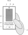
- Fig. 10 shows an example of a screen display in S101, the confirmation judgment of the operation description of the authentication terminal 100 in Embodiment 1.
- Fig. 11 shows an example of the operation of the authentication terminal in the confirmation judgment S101 of the operation description of the authentication terminal 100 in Embodiment 1.
- the confirmation judgment of the operation explanation is a process to ensure that the operator of the authentication terminal confirms the operation method explained by the authentication terminal 100, and an example of the details of the process is described below, using Fig. 9 .
- the authentication terminal 100 instructs the operator of the authentication terminal to confirm the presentation position of the biometric part to the authentication terminal by displaying on display 4 (S1010).
- display 4 displays an image 19 showing the back of the authentication terminal 100, a message 20 indicating that the camera position is to be confirmed, and a button 5 to notify the authentication terminal 100 that the operator has completed confirmation.
- button 5 is inactive and cannot be pressed.
- the authentication terminal 100 detects changes in the posture of the authentication terminal 100 with the posture detector 6 (S1011). For example, by detecting the rotation generated by turning the terminal over as shown in Fig. 11 , the authentication terminal 100 can know that the operator has confirmed the position of the rear camera 14 located on the back of the authentication terminal 100. The fact that the operator has confirmed the presentation position of the biometric part by detecting the posture change of the authentication terminal 100 may be explicitly indicated to the operator, such as by displaying it on the display 4. If the posture change is sufficiently small, the instruction to confirm the presentation position of the biological body (S1010) is performed again. If a change in posture is detected, the authentication terminal 100 activates the button 5 so that it can be pressed (S1012).
- the authentication terminal 100 checks whether button 5 has been pressed (S1013). If it has not been pressed, it waits until it is pressed. If it is pressed, it assumes that the terminal operator has finished confirming the explanation of the operation method and terminates the process (S1014).
- Fig. 12 shows an example of the screen display in S102, the instruction for the presentation posture in Embodiment 1.
- Fig. 13 shows how the vital information displayed in the S102 instruction for the presentation posture is generated in Embodiment 1.
- the presentation posture instruction (S102) in Fig. 5 is a process for detecting impersonation with high accuracy and for implementing biometric authentication, and an example of the details of the process is described below.
- Authentication terminal 100 captures finger 17 of the operator with rear camera 14 and extracts vital information A from the video obtained by the method described below or other methods.
- the vital information A is, for example, a pulse wave, heart rate, and time-continuous signals correlated therewith.
- the extracted vital information A23 is displayed on the display 4, for example, as a waveform image 21 (see Fig. 12 ) representing a waveform with time on the horizontal axis and signal intensity on the vertical axis, together with an image 22 showing a face captured by the front camera 15.
- false vital information 26 that has different amplitude, period, phase, and other characteristics from the extracted vital information A23 may be displayed instead as the waveform image 21. This is because the extracted vital information A23 is used to confirm whether the operator of the authentication terminal 100 and the person to be authenticated are the same person by the method described below and displaying the extracted vital information A23 as it is may lead to an increased security risk.
- the extracted vital information A23 can be separated into signal component 24 and noise component 25, and by adding the noise component 25 to the fake vital information 26, fake vital information 27 containing noise and disturbance can be generated and displayed instead as a waveform image 21.
- the degree of noise and disturbance in the extracted vital information A23 will be notified to the operator, and the finger presentation posture can be improved by displaying a message 20 together with the finger presentation method to weaken the disturbance.
- This is expected to reduce some of the noise components 25 such as noise and disturbance contained in the extracted vital information A23, which will make the impersonation detection described below more accurate.
- the absolute value of the difference between the extracted vital information A23 and its time average is used as the noise component 25 in the extracted vital information A23, which can be obtained simply.
- Fig. 14 is a flowchart showing the process of S103 for obtaining vital and biometric authentication information by the authentication terminal 100 in Embodiment 1. The process shown in Fig. 14 is processed by the control of authentication processing unit 2.
- the rear camera 14 and the front camera 15 capture the fingers 17 and face 18 of the operator grasping the terminal, respectively.
- Vital information A is obtained from video A obtained by capturing 17 fingers
- vital information B and biometric authentication information are obtained from video B obtained by capturing 18 faces. Since vital information B and biometric authentication information are acquired from the same data respectively, when it is verified that vital information A and B originate from the same person by the method described below, it can be confirmed that biometric authentication information is extracted from the biometric site presented by the true operator who has not been impersonated.
- the influence of temporal changes in vital information such as pulse wave and heart rate can be reduced. An example of the details of the process is described below.
- the authentication terminal 100 takes a picture of finger 17 in contact with the first camera, the rear camera 14, to acquire video A (S1031).
- the changes in blood flow that accompany the pulsation of the heart can be captured as changes in the brightness of the image.
- a light-emitting device e.g., a torch
- the image may be captured while turning it on. This allows the light emitted from the light-emitting device to scatter through the finger, improving the visibility of the blood vessels by the rear camera 14 and allowing higher definition measurement of the changes in blood flow rate at the fingertip.
- the authentication terminal 100 acquires vital information A from the video A acquired from the rear camera 14 and stores it in memory 10 (S1032).
- the luminance signal in one dimension in the time direction which is the average value in the spatial direction of the luminance of each image per unit time that constitutes the moving image A, may be used as the vital information A.
- the image comprising Video A is an RGB image
- the signal value of a green (G) pixel which has a higher S/N ratio with a larger number of pixels in the photosensors than red (R) and blue (B), may be used as the luminance of that pixel.
- the RGB image may be converted to another color space such as YUV or HSV, and the luminance signal such as Y for YUV or V for HSV may be used as the luminance.
- the average of the R, G, and B pixel values of each pixel may be used as the luminance of that pixel.
- the luminance signal of the vital information A obtained above repeats periodically, becoming larger and smaller.
- the average value of the luminance signal over a certain time interval in the vital information A which is a time-continuous luminance signal, may be obtained and that value may be used as the vital information A.
- the authentication terminal 100 uses the second camera, the front camera 15, to capture the face 18 presented on the front camera 15 and acquire the video B (S1033).
- Vital information B is acquired from the video B and stored in memory 10 (S1034).
- the position and size of face 18 are detected from video B using an arbitrary face detection algorithm, and the respective feature values, etc. are acquired as biometric authentication information and stored in memory 10 (S1035).
- the acquisition of biometric authentication information may be performed simultaneously with the acquisition of video A (S1031) and vital information A (S1032) from the rear camera 14, and especially with the acquisition of video A from the rear camera 14 and authentication processing unit 2, front camera 15 and if there are constraints on the maximum data transfer volume between authentication processing unit 2 or the processing capacity of CPU 9, they may be carried out sequentially.
- the area occupied by the skin is extracted from the face 18 detected by an arbitrary skin area extraction algorithm, the average luminance in the spatial direction is calculated for each of the three channels (R, G, and B) from the extracted skin area, and the pulse wave is obtained by acquiring a time-series luminance signal.
- a moving average filter is applied to the acquired time-series luminance signals for the three channels in the temporal direction to reduce the effect of noise.
- the time-series luminance signal for three channels, from which noise has been removed using ICA (Independent Component Analysis) or other techniques is decomposed into multiple independent components that make up that signal.
- the components that compose the color tone of the face 18 image obtained from the front camera 15, which is mainly sensitive to visible light wavelengths, include melanin pigments in the epidermal layer of the skin, blood vessels in the dermal layer, and fat tissue in the subcutaneous tissue, etc.
- the above ICA technique enables the acquisition of the luminance components in which blood vessels are dominant.
- the acquired time series of blood vessel-dominant luminance components may be used as vital information B, for example, as the pulse wave of face 18.
- the authentication terminal 100 acquires biometric authentication information from the video B and vital information B acquired from the front camera 15 (S1035).
- biometric authentication information For example, feature points representing the position and shape of the eyes, nose, mouth, etc., may be extracted from the images of each frame comprising the acquired video B and used as biometric authentication information, or features extracted from the face area of the images of each frame comprising the video B using Deep Learning technologies such as FaceNet, ArcFace, and BiometricFace may be used as biometric authentication information.
- Information such as amplitude, period, phase, and other statistics from the extracted vital information B may also be used as biometric information.
- Fig. 15 shows an example of how the authentication terminal 100 shields the entire lens with a finger in S104 for quality judgment of the data to be acquired by the authentication terminal 100 and an example of the video obtained in Embodiment 1.
- Fig. 16 shows an example of the video obtained and how only a part of the lens of the rear camera 14 is shielded by finger 17 in S104 (see Fig. 5 ), which is a quality judgment of the data obtained by the authentication terminal 100 in Embodiment 1.
- the acquired information quality judgment it is determined whether the video, vital information, and biometric authentication information acquired from the rear camera 14 and front camera 15 are of appropriate quality for implementing impersonation detection and biometric authentication.
- the rear camera 14 when finger 17 is in contact with the lens of the rear camera 14 to take a picture of finger 17, if finger 17 is correctly shielding the entire lens, the rear camera 14 produces a movie 28 in which the entire image has a reddish cast and flickers significantly over time.
- the rear camera 14 if finger 17 is shielding only a part of the lens of the rear camera 14 as shown in Fig. 16 , the rear camera 14 produces a movie 28 in which only a part of the image is reddish and the blinking over time is small. In the video 28 with small blinking, the area occupied by finger 17 becomes small and the background other than the finger may also be reflected.
- the vital information A extracted from the video 28 with small blinking contains unnecessary information other than the blood flow rate of the fingertip, leading to a decrease in the accuracy of the spoofing detection described below. Therefore, it is possible to extract feature values related to texture, edge, color, etc. from the video 28 with small flickering, and determine whether there is reflection of objects including background other than the fingertips based on the trend of the feature values. If there is a reflection of an object, the system may return to the presentation posture instruction (S102) and instruct the operator to reposition the hand.
- S102 presentation posture instruction
- vital information A, vital information B, and biometric authentication information it may be judged whether each information can be extracted stably.
- vital information For example, if Vital Information A and Vital Information B are collectively referred to as vital information, the absolute value of the difference between the vital information after noise reduction obtained by applying a moving average filter in the time direction to the vital information and the original vital information signal is integrated in the time direction. This value can be regarded as the sum of the amount of noise in the vital information. If the value is greater than a predetermined threshold value, the extracted vital information considered to be unstable and the camera may return to the presentation posture instruction (S102), perform appropriate posture guidance, and redo the shooting.
- S102 presentation posture instruction
- the degree of difference of biometric authentication information between different frames is calculated.
- the degree of difference indicates how much the biometric authentication information has changed at each time during the recording.
- the biometric authentication information should be stable. Therefore, if the degree of difference is greater than a predetermined threshold value, the extracted biometric authentication information considered to be unstable, and the process may return to the presentation posture instruction (S102), perform appropriate posture guidance, and redo the shooting.
- the following process may be performed, for example.
- the amplitude, period, phase, etc. are calculated for vital information A and B, which are acquired simultaneously from different biological areas, respectively. If these vital information were acquired from the same person, the difference in period corresponding to the heart rate is sufficiently small between vital information A and B. In other words, if the cycles are significantly different, the vital information A and B were collected from different persons, and there is a high possibility that the operator is impersonating the person to be authenticated for biometric authentication. In this case, the system notifies the operator of the failure of enrollment or authentication by displaying a message on the display 4, etc., and then terminates the process.
- the display 4 shows an example of a presentation in which the finger 17 is pressed hard against the rear camera 14 and text instructing the user to assume a similar posture, and then the rear camera 14 is used again to capture the finger, and vital information is obtained from the resulting video.
- the flickering of the resulting video becomes weaker because the blood circulation in the finger deteriorates.
- the rear camera 14 takes a picture of finger 17 to obtain a video.
- objects that are not in contact with the rear camera 14 will vibrate and appear in the video, while objects that are in contact will vibrate in synchronization with the authentication terminal, so they will appear in the resulting video without vibrating.
- By checking the presence or absence of this vibration it can be confirmed that finger 17 is presented in contact with the lens of the rear camera 14 and that no fake object is presented in a non-contact manner.
- Fig. 17 shows an example of the authentication in Embodiment 2 observed from the rear side of the authentication terminal.
- Fig. 18 shows an example of the authentication in Embodiment 2 observed from the front side of the authentication terminal.
- biometric authentication is performed by an authentication terminal 100 equipped with a rear camera 14, a front camera 15, and a display 4 outside the housing 16, after confirming that the operator of the terminal is the person to be authenticated, as assumed by the authentication terminal 100.
- the operator of the terminal takes a picture of finger 17 by the front camera 15 located on the front of housing 16, as shown in Fig. 18 , and the other finger 17 by the rear camera 14 located on the back of housing 16, as shown in Fig. 17 .
- Vital information is extracted from the image obtained from the front camera 15, and vital and biometric authentication information is extracted from the image obtained from the rear camera 14. After confirming that the respective vital information originates from the same person, biometric authentication can be performed based on the biometric authentication information extracted from the finger 17, thereby preventing impersonation by others while performing biometric authentication.
- the configuration of the authentication terminal 100 in Embodiment 2 is the same as in the first example.
- the processing flowchart the time of registration and authentication also has many points in common with Embodiment 1, but differs in that the finger 17 is not presented to the rear camera 14 by touching the lens, but by holding it over the camera without making contact. It also differs in that it does not present the face to the front camera 15, but presents the finger 17 holding the authentication terminal 100 by touching the lens. This makes it possible to perform biometric authentication even when biometric authentication using the face in Embodiment 1 is difficult due to the presence or absence of a mask, glasses, makeup, hair style, etc. that are different from those used when the biometric authentication is registered.
- a bill guide image 29 representing the approximate shape of the finger and a message 20 instructing the operator to present finger 17 may be displayed on display 4.
- the bill guide image 29 shown on the display 4 may be enlarged to show only the finger area of the finger 17. This allows the area of the finger to be captured with higher resolution than when the rear camera 14 is used to capture the entire finger 17, and is expected to improve the authentication accuracy when spatially detailed patterns such as wrinkles on the finger surface and blood vessels near the finger surface are used as biometric authentication information.
- the illumination of the display 4 may be temporarily increased. This allows light emitted from the display 4 to penetrate and scatter through finger 17, improving the visibility of blood vessels in the moving image obtained by capturing the scene with the front camera 15, and enabling highly accurate acquisition of vital information such as pulse wave and heart rate.
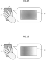
- Fig. 19 shows an example of the authentication in Embodiment 3 observed from the rear side of the authentication terminal.
- Fig. 20 shows an example of the authentication in Embodiment 3 observed from the front side of the authentication terminal.
- biometric authentication is performed using an authentication terminal 100 equipped with a rear camera 14, front camera 15, and display 4 outside housing 16, after confirming that the terminal operator is the person to be authenticated as envisioned by the biometric authentication system.
- the terminal operator takes a picture of face 18 with front camera 15 and takes a picture of finger 17 with rear camera 14.
- Vital and biometric authentication information is extracted from the image obtained from the front camera 15, and vital and biometric authentication information is extracted from the image obtained from the rear camera 14.
- biometric authentication can be performed based on the biometric authentication information extracted from face 18 and finger 17, thereby preventing impersonation by others while performing biometric authentication.
- the configuration of the authentication terminal 100 in Embodiment 3 is the same as in Embodiment 1.
- the processing flowchart of the time of registration and authentication also has many points in common with Embodiment 1, but the difference is that the hand is not presented to the rear camera 14 by touching the lens with the finger, but by holding the camera over the finger without touching it.
- the difference is that not only vital information, but also biometric authentication information is extracted from the biometric part presented to the rear camera 14.
- biometric authentication can be performed with higher accuracy than when biometric authentication is performed on face 18 alone or finger 17 alone.
- the biometric authentication information may be combined with the face photograph on an official identification card, such as a driver's license or national identification (ID) card.
- an official identification card such as a driver's license or national identification (ID) card.
- ID national identification
- the personal information entered in the system may be checked against the personal information on the official identification card, and the system can be registered by linking the system's registration information with the person's facial information by matching the face of the person photographed with the camera that was activated at the time of system registration with the face photograph on the official identification card.
- the image 22 showing face 18 obtained by the front camera 15 during the capture and the image 30 showing finger 17 obtained by the rear camera may be displayed on display 4. If the biological site is more difficult to present for finger 17, which needs to be presented to the rear camera 14 by making full use of the bill guide image 29, than for face 18, which can be captured naturally by the front camera 15 by looking at the display 4, the reflected image 22 of face 18 by displaying a larger image 30 of finger 17 on the display 4 than the image 22 of face 18, the operator can present finger 17 more easily.
- Fig. 21 shows an example of the authentication in Embodiment 4.
- image capture unit 1 consists of one front camera 15.
- one biological part e.g., finger 17 in contact with the lens of the front camera 15
- vital information A is extracted from the obtained video.
- the other biological part e.g., face 18, is photographed and the vital information B and biometric authentication information are extracted from the obtained video.
- biometric authentication is performed based on the biometric authentication information extracted from the video from which the vital information B was derived. This allows the operator to be authenticated by biometric authentication while preventing impersonation by others, even when image capture unit 1 consists of a single camera.
- each of the above compositions, functions, processing units, processing means, etc. may be realized in hardware by designing some or all of them, for example, in an integrated circuit.
- each of the above compositions, functions, etc. may be realized in software by a processor interpreting and executing a program that realizes the respective function.
- Information such as programs, tables, files, etc. that realize each function may be stored in a storage device such as a nonvolatile semiconductor memory, hard disk drive, SSD (Solid State Drive), or a computer-readable non-transient data storage medium such as an IC card, SD card, DVD, etc.
- control and information lines are those considered necessary for illustrative purposes, and not all control and information lines are necessarily shown in the product. In reality, almost all components may be considered to be interconnected.
Landscapes
- Engineering & Computer Science (AREA)
- Physics & Mathematics (AREA)
- Health & Medical Sciences (AREA)
- Theoretical Computer Science (AREA)
- General Physics & Mathematics (AREA)
- Multimedia (AREA)
- Life Sciences & Earth Sciences (AREA)
- Human Computer Interaction (AREA)
- General Health & Medical Sciences (AREA)
- Biophysics (AREA)
- Heart & Thoracic Surgery (AREA)
- Computer Security & Cryptography (AREA)
- Physiology (AREA)
- Cardiology (AREA)
- Oral & Maxillofacial Surgery (AREA)
- Medical Informatics (AREA)
- Biomedical Technology (AREA)
- Pathology (AREA)
- Veterinary Medicine (AREA)
- Public Health (AREA)
- Animal Behavior & Ethology (AREA)
- Surgery (AREA)
- Molecular Biology (AREA)
- Software Systems (AREA)
- General Engineering & Computer Science (AREA)
- Computer Hardware Design (AREA)
- Signal Processing (AREA)
- Dentistry (AREA)
- Computer Vision & Pattern Recognition (AREA)
- Measurement Of The Respiration, Hearing Ability, Form, And Blood Characteristics Of Living Organisms (AREA)
- Collating Specific Patterns (AREA)
- Measuring Pulse, Heart Rate, Blood Pressure Or Blood Flow (AREA)
Abstract
Authentication is performed by confirming that the true operator presents his/her own biometric authentication information at a common portable information terminal. The biometric authentication system has an image capture unit that acquires first and second image data of different biometric areas of an operator during a predetermined period, a display that displays a guide to guide the operator to the location of the biometric area in order to capture different biometric areas of the operator, and a memory that stores biometric authentication information of the operator in advance. Furthermore, the first vital information and the second vital information are extracted from the image data of the different biometric areas, respectively, the identity of the operator is determined based on the first vital information and the second vital information, and if the identity of the operator is confirmed, the biometric authentication is performed.
Description
- This invention relates to a technique for authenticating an individual using a living body.
- Traditionally, memory authentication such as ID (Identification) and PW (Password), and object authentication such as physical locks or IC (Integrated Circuit) cards have been widely used as means of personal authentication for access control such as access control, attendance ticking, and computer login.
- However, these forms of authentication carry the risk of forgetting or losing the device. In contrast, biometric authentication has been used in recent years without these risks. Biometric authentication uses a device equipped with a sensor to read biometric authentication information, and is used to control access to personal computers (PCs), bank ATMs (Automated Teller Machines), room entrances, lockers, and other devices. In particular, with the recent spread of portable information terminals such as smartphones and tablets, biometric authentication can be easily performed on portable information terminals in an increasing number of cases. On the other hand, biometric authentication has become problematic when someone impersonates a person by presenting a photo or display of the person's image or an object that imitates the person's body. Therefore, in order for users to use biometric authentication safely and securely, it is necessary to take measures to prevent such impersonation.
-
Patent document 1 discloses a technique for extracting vital information from the face area of a person in time-continuous captured images obtained from an imaging device, and based on the vital information, preventing fraud by means of photographs, etc. of that person. -
Patent Document 1JP 2017-10210 A - The problem with
Patent Document 1 is that by presenting a video showing a person's reflection on a display to an authentication terminal, it is easy for someone else to impersonate that person and perform biometric authentication. - Therefore, the purpose of the present invention is to provide a biometric authentication system and a method to authenticate an operator by confirming that the operator presents his/her own biometric authentication information on a common portable information terminal.
- The biometric authentication system comprises an image capturing unit being configured to acquire a first image data and a second image data of different biological areas or regions, hereinafter areas, of an operator during a predetermined period, a display displaying a location guidance of the biological area to the operator for capturing different biological areas of the operator, a memory stores biometric authentication information of the operator in advance, and an authentication processor being configured to extract a first vital information and a second vital information from the first image data and the second image data of the different of the biological areas, respectively, determine an identity of the operator based on the first and second vital information, if the identity of the operator is confirmed, extract a biometric information of the operator from the second image data, and perform biometric authentication based on the extracted biometric information and the biometric information stored in the memory unit.
- According to the present invention, if the identity of multiple vital information obtained from multiple different biological areas or regions acquired by a general portable terminal equipped with an image capture unit that acquires image data is confirmed, the operator can perform biometric authentication using his or her own biometric authentication information.
-
-
Fig. 1 shows an example of a block diagram of the entire biometric authentication system inEmbodiment 1. -
Fig. 2 shows an example of the functional block diagram ofauthentication processing unit 2 inEmbodiment 1. -
Fig. 3 shows an example of the authentication ofEmbodiment 1 observed from the rear side of the authentication terminal. -
Fig. 4 shows an example of the authentication ofEmbodiment 1 observed from the front side of the authentication terminal. -
Fig. 5 shows a flowchart of the registration process inEmbodiment 1. -
Fig. 6 is a flowchart showing the process during authentication inEmbodiment 1. -
Fig. 7 shows an example of a screen display guiding the presentation of a biometric site to the image capture unit located on the back of the authentication terminal inEmbodiment 1. -
Fig. 8 shows an example of a screen display guiding the presentation of a biometric site to the image capture unit placed in front of the authentication terminal inEmbodiment 1. -
Fig. 9 is a flowchart showing the process of S101, the confirmation decision of the operation description inEmbodiment 1. -
Fig. 10 shows an example of the screen display in S101, the confirmation decision of the work description inEmbodiment 1. -
Fig. 11 shows an example of the operation of the authentication terminal in the confirmation decision S101 of the operation description inEmbodiment 1. -
Fig. 12 shows an example of the screen display in S102, the instruction for the presentation posture inEmbodiment 1. -
Fig. 13 shows how the vital information to be displayed in the presentation posture instruction S102 is generated inEmbodiment 1. -
Fig. 14 is a flowchart showing the process of S103 for obtaining biometric and vital information inEmbodiment 1. -
Fig. 15 shows an example of capturing images with a finger shielding the entire lens and the obtained video in S104, the quality judgment of the acquisition information inEmbodiment 1. -
Fig. 16 shows an example of capturing images by shielding only a part of the lens with a finger in S104, the quality judgment of the acquisition information, and an example of the obtained video in the example 1. -
Fig. 17 shows an example of the authentication inEmbodiment 2 observed from the rear side of the authentication terminal. -
Fig. 18 shows an example of the authentication observed from the front side of the authentication terminal inEmbodiment 2. -
Fig. 19 shows an example of the authentication observed from the rear side of the authentication terminal inEmbodiment 3. -
Fig. 20 shows an example of the authentication observed from the front side of the authentication terminal inEmbodiment 3. -
Fig. 21 shows an example an authentication inEmbodiment 4. - In the following description, _one or more processors constitute an authentication processor. The at least one processor is typically a microprocessor such as a CPU (Central Processing Unit), but may also be another type of processor such as a GPU (Graphics Processing Unit). The at least one processor may be single-core or multi-core.
- The at least one processor is also a hardware circuit (e.g., Field-Programmable Gate Array (FPGA) or Application Specific Integrated Circuit (ASIC)) that performs part or all of the processing in a broad sense.
- In the following description, the "program" may be used as the subject of the process, but since the program, when executed by a processor, performs a defined process while using memory and/or interface(s) , etc., as appropriate, the subject of the process may be the processor (or the subject of the processing may be the processor (or a device such as a controller with a processor).
- The program may be installed in a device such as a computer, or may be on a (e.g., non-transitory) recording medium that can be read by, for example, a program distribution server or a computer. In the following description, two or more programs may be realized as one program, or one program may be realized as two or more programs.
- The biometric authentication system may be a distributed system consisting of one or more (typically multiple) physical devices.
- In the following explanations, reference codes (or common codes among reference codes) may be used when elements of the same type are described without distinguishing between them, and element identification numbers (or reference codes) may be used when elements of the same type are described separately.
- Various embodiments or examples of the invention are described below with reference to the accompanying drawings. Although the accompanying drawings show specific examples in accordance with the principles of the invention, they are for the understanding of the invention and are not to be used to interpret the invention in a limiting manner.
-
Fig. 1 shows an example of a block diagram of the entire biometric authentication system ofEmbodiment 1. - In the embodiments, the biometric authentication system is described as a general portable terminal such as a smartphone or tablet, i.e.,
authentication terminal 100. It goes without saying that the invention may be configured not only as anauthentication terminal 100 but also as a device with all or some of the components shown inFig. 1 mounted in a housing. In that case, the biometric authentication system may be a biometric authentication device including the authentication process. Alternatively, the authentication process may be performed outside the authentication terminal, and the authentication terminal may be configured as an authentication terminal specialized for acquiring biometric images. - The
authentication terminal 100 ofEmbodiment 1 includes animage capture unit 1, anauthentication processing unit 2, amemory 3, adisplay 4, aninput unit 5, aposture detector 6 and avibrator 7, anaudio output 8. -
Image capture unit 1 is, for example, a camera, which acquires images containing biometric authentication information by capturing the subject (operator of the authentication terminal), and inputs the acquired images toauthentication processing unit 2. The camera, for example, has three types of photosensors that are sensitive to blue (B), green (G), and red (R), respectively, and these are arranged in a grid pattern for each pixel. The spectral sensitivity of each photosensitive element has a peak sensitivity around 480 nm for blue, 550 nm for green, and 620 nm for red, for example. By photographing with the camera, the spatial luminance distribution of light with peaks of sensitivity at each of the three different wavelengths can be obtained. -
Authentication processing unit 2 generates biometric authentication information by image processing the image input fromimage capture unit 1, and performs authentication processing based on the biometric authentication information. The authentication processing unit may be configured by includingimage capture unit 1 in the image processing function ofauthentication processing unit 2. In either case,authentication processing unit 2 is equipped with an image processing function. - The
authentication processing unit 2 includes a central processing unit (CPU: Central Processing Unit) 9, amemory 10, and various interfaces 11 (IF: Interface). Thememory 10 stores the program executed byCPU 9. In addition, thememory 10 temporarily stores images input fromimage capture unit 1.Interface 11 connectsauthentication processing unit 2 to external devices. Specifically, theinterface 11 is connected to theimage capture unit 1,memory 3,display 4,input unit 5,posture detector 6,vibrator 7, andaudio output 8. -
Fig. 2 shows an example of the functional block diagram ofauthentication processing unit 2 inEmbodiment 1. - The
authentication processing unit 2 is equipped with anauthentication unit 12 and aregistration unit 13. Theauthentication unit 12 processes the biometric authentication information obtained by image processing of the image input from the image capture unit 1 (hereinafter referred to as input data) and the biometric authentication information registered in advance in memory 3 (hereinafter referred to as biometric authentication information). - Returning to
Fig. 1 , thememory 3 stores user registration data in advance. The registration data (biometric authentication information) is information for matching users, such as images of finger vein patterns and features such as nose, eyes, and mouth that can be used in face recognition. Usually, the finger vein pattern image is an image of blood vessels (finger veins) mainly distributed under the skin on the palm side of the finger as a dark shadow pattern. - The
display 4 is, for example, a display and outputs information received fromauthentication processing unit 2 in the form of video. In the following description,display 4 may be referred to asdisplay 4. Thedisplay 4 displays a guide to guide the operator to one of the biometric areas to capture different biometric areas of the operator. Theinput unit 5 may be a physical keyboard with buttons that are physically pressed to input letters and numbers, or it may be a virtual keyboard in which an image that imitates a physical keyboard is displayed on thedisplay 4 and a pointing device such as a mouse, touch panel, or pen is used to press the buttons on the image that imitates the keyboard. In the following description,Input unit 5 may be referred to askeyboard 5 orbutton 5. -
Posture detector 6 is, for example, a gyro sensor, an acceleration sensor, a geomagnetic sensor, etc., and detects posture information such as the movement and orientation of part or all of theauthentication terminal 100, and inputs it to theauthentication processing unit 2.Audio output 8 is a speaker, for example, that outputs audio information received fromauthentication processing unit 2. In the following description,audio output 8 may be referred to asspeaker 8. -
Fig. 3 shows an example of the authentication ofEmbodiment 1 observed from the rear side of theauthentication terminal 100. -
Fig. 4 shows an example of the authentication ofEmbodiment 1 observed from the front side of theauthentication terminal 100. - In
Embodiment 1, biometric authentication is performed using anauthentication terminal 100 equipped with arear camera 14, afront camera 15, and adisplay 4 outsidehousing 16, after confirming that the operator of the authentication terminal is the person to be authenticated, as assumed by the biometric authentication system. The biometric authentication is performed after confirming that the operator of the authentication terminal is the person to be authenticated in the biometric authentication system. - As shown in
Fig. 3 andFig. 4 , the operator of the authentication terminal presentsfinger 17, which grasps theauthentication terminal 100, andface 18, which confirms the screen of the terminal, according to the instructions displayed on thedisplay 4 described below. Theauthentication terminal 100 takes a picture offinger 17 with therear camera 14 located on the back of thehousing 16 of theauthentication terminal 100, and takes a picture offace 18 with thefront camera 15 located on the front of thehousing 16 of theauthentication terminal 100. Vital information A is extracted from the image obtained from therear camera 14, and vital information B of the operator is extracted from the image obtained from thefront camera 15. - The vital information A extracted from the image of the
rear camera 14 is, for example, the pulse wave of the hand orfinger 17 and the vital information B obtained from thefront camera 15 is, for example, the pulse wave of theface 18. The biometric authentication information extracted from the image of thefront camera 15 is, for example, the features of the nose, eyes, mouth, etc. of theface 18 used in face recognition technology. - In
Embodiment 1, the operator impersonation can be prevented by confirming that the vital information such as pulse wave acquired by therear camera 14 andfront camera 15 over a predetermined period originates from the same person. After confirming the identity of the operator, biometric authentication can be performed using the biometric authentication information presented by the operator of the authentication terminal. The predetermined period means that vital information A and B are acquired by therear camera 14 andfront camera 15 at the same timing. The same timing means that in addition to acquiring vital information A and B at the same time, they may be acquired at different times during the period in which this authentication process is performed. Thus, the period during which two vital information is acquired for authentication is called the authentication period, and when biometric authentication information is registered, it is called the registration period. The authentication and enrollment periods are predetermined periods of time and can be set to any time, for example, 10 seconds. -
Fig. 5 is a flowchart showing the process at the time of registration at theauthentication terminal 100 inEmbodiment 1. The process shown inFig. 5 is processed under the control ofauthentication processing unit 2. - First, the
authentication terminal 100 explains the authentication method to the operator of theauthentication terminal 100 using thedisplay 4 and speaker 8 (S100). - Next, the
authentication terminal 100 checks whether the operator understands the explanation of the authentication method (S100) usinginput unit 5 and posture detector 6 (S101). - Next, the
authentication terminal 100 displays, on thedisplay 4, an image imitating a living body that serves as a sample of the presentation of the biometric part, biometric authentication information extracted from the video or animation obtained from theimage capture unit 1 described below, and text indicating a specific presentation posture (S102). - Next, the
authentication terminal 100 uses therear camera 14 andfront camera 15, which areimage capture unit 1, to capture the operator's body part during the registration period and obtains vital information and biometric authentication information from the obtained video (S103). In other words, vital information such as pulse wave is acquired from therear camera 14 andfront camera 15, and biometric authentication information, which are feature values such as nose, mouth, and eyes used in face recognition technology, is acquired from thefront camera 15. - Next,
authentication processing unit 2 determines whether the quality of the vital information extracted from the video acquired by therear camera 14 andfront camera 15 and the biometric authentication information extracted from the video acquired by thefront camera 15 is appropriate (S104). If the quality is judged to be low and not appropriate, the presentation posture is instructed to increase the quality (S102), and the biometric authentication information acquisition (S103) is redone. If the quality is judged to be high and appropriate, proceed to the next process. - Next,
authentication processing unit 2 determines whether or not another person is impersonating the operator (S105) based on the acquiredface 18 and the video taken offinger 17. Determining whether there is impersonation (S105) is a process to confirm the identity of the operator. Specifically, vital information A and vital information B acquired by therear camera 14 andfront camera 15, respectively, are stored inmemory 10. Then, the vital information A and B stored inmemory 10 are compared byauthentication unit 12. For example, the amplitude, period, phase, etc. of vital information A and B, which are simultaneously acquired from different biological sites, are calculated respectively. If these vital information were obtained from the same person, the difference in the cycle corresponding to the heart rate is sufficiently small between vital information A and B to determine that there is no spoofing. - If the cycles are significantly different, it is determined that vital information A and vital information B were collected by different persons and that the operator is impersonating the biometric subject. After the determination of impersonation, the vital information A and B stored in
memory 10 are deleted frommemory 10. - If it is determined that there is spoofing by another person, a message indicating that registration failed is displayed on the
display 4, and the registration process is terminated (Sill) . If it is determined that there is no spoofing by others, proceed to the next process. - Next,
authentication processing unit 2 temporarily holds the extracted biometric authentication information data inmemory 10 as a candidate for enrollment (S106). - Next,
authentication processing unit 2 checks whether the number of registration candidate data held inmemory 10 is sufficient to the preset number (S107). If the number of candidate registration data is not sufficient, the process returns to the presentation posture instruction (S102) and continues shooting. If the number of registration candidate data is satisfied, proceed to the next process. - Next,
authentication processing unit 2 calculates the degree of difference between the candidate enrollment data (between multiple biometric identifiers) added in step S106 (S108). - Next,
authentication processing unit 2 checks whether the calculated discrepancy is below the pre-set registration threshold (S109). If it is above the threshold, it indicates on thedisplay 4 that registration has failed, discards the registration candidate data temporarily stored inmemory 10, and terminates the registration process (Sill). If the value is below the threshold, thedisplay 4 indicates that the registration was successful, the registration candidate data temporarily held inmemory 10 is saved inmemory 3, and the registration process is completed (S110). - In
memory 3, biometric authentication information of the same operator is stored in association with the ID that uniquely identifies the operator. Therefore, in the explanation of the authentication method in step S100, the operator may be instructed to enter the ID. -
Fig. 6 is a flowchart showing the processing during authentication of theauthentication terminal 100 inEmbodiment 1. The process shown inFig. 6 is handled under the control ofauthentication processing unit 2. - Among the process flows during authentication, the presentation posture instruction (S102), acquisition of vital and biometric authentication information (S103), quality judgment of acquired information (S104), and judgment as to whether or not impersonation occurs (S105) are identical to the process flow during registration shown in
Fig. 5 . - In acquiring vital and biometric authentication information in step S103, the images of
finger 17 and face 18 of the operator of theauthentication terminal 100 are acquired by the two cameras of theimage capture unit 1 of theauthentication terminal 100,rear camera 14 andfront camera 15, and the same vital information A and B are acquired from the different images at the same timing. The same timing means that vital information A and vital information B may be acquired at the same time, or at different times during the period in which this authentication process is being performed. Thus, the period during which two vital information is acquired for authentication is called the authentication period. The authentication period is a predetermined period and can be set to any time, for example, 10 seconds. - After the spoofing presence/absence judgment (S105),
authentication processing unit 2 calculates the degree of difference between the biometric authentication information extracted from the image captured byimage capture unit 1 and the biometric authentication information of the operator that is pre-registered in memory 3 (S112). For this purpose, in the presentation posture instruction (S102), the ID of the operator is instructed to be input, the input of the operator's ID is accepted, and the biometric authentication information registered in correspondence with the operator's ID is read frommemory 3. - Next,
authentication processing unit 2 checks whether the calculated discrepancy is below the pre-set authentication threshold (S113). If it is above the threshold, thedisplay 4 indicates that authentication failed, and the authentication process is terminated (S115). If it is below the threshold, thedisplay 4 indicates that the authentication was successful, and the authentication process ends (S114). -
Fig. 7 shows an example of a screen display of a guide guiding the presentation of the biometric site to therear camera 14 of theauthentication terminal 100 ofEmbodiment 1 in step S100. -
Fig. 8 shows an example of a screen display of a guide guiding the presentation of the biometric site to thefront camera 15 of theauthentication terminal 100 ofEmbodiment 1 in step S100. - In the explanation of the operation method (S100), an
image 19 showing an example of the presentation of a biometric part and amessage 20 showing how to present the biometric part are displayed on thedisplay 4, mainly to indicate which biometric part of the operator is to be presented at which position on theauthentication terminal 100. The content of themessage 20 may also be read out by thespeaker 8. -
Fig. 9 is a flowchart showing the S101 process of the confirmation judgment of the operation description of theauthentication terminal 100 inEmbodiment 1. The process shown inFig. 9 is processed by the control ofauthentication processing unit 2. -
Fig. 10 shows an example of a screen display in S101, the confirmation judgment of the operation description of theauthentication terminal 100 inEmbodiment 1. -
Fig. 11 shows an example of the operation of the authentication terminal in the confirmation judgment S101 of the operation description of theauthentication terminal 100 inEmbodiment 1. - The confirmation judgment of the operation explanation (S101) is a process to ensure that the operator of the authentication terminal confirms the operation method explained by the
authentication terminal 100, and an example of the details of the process is described below, usingFig. 9 . - First, the
authentication terminal 100 instructs the operator of the authentication terminal to confirm the presentation position of the biometric part to the authentication terminal by displaying on display 4 (S1010). For example, as shown inFig. 10 ,display 4 displays animage 19 showing the back of theauthentication terminal 100, amessage 20 indicating that the camera position is to be confirmed, and abutton 5 to notify theauthentication terminal 100 that the operator has completed confirmation. Until the operator complies with the contents ofmessage 20,button 5 is inactive and cannot be pressed. - Next, the
authentication terminal 100 detects changes in the posture of theauthentication terminal 100 with the posture detector 6 (S1011). For example, by detecting the rotation generated by turning the terminal over as shown inFig. 11 , theauthentication terminal 100 can know that the operator has confirmed the position of therear camera 14 located on the back of theauthentication terminal 100. The fact that the operator has confirmed the presentation position of the biometric part by detecting the posture change of theauthentication terminal 100 may be explicitly indicated to the operator, such as by displaying it on thedisplay 4. If the posture change is sufficiently small, the instruction to confirm the presentation position of the biological body (S1010) is performed again. If a change in posture is detected, theauthentication terminal 100 activates thebutton 5 so that it can be pressed (S1012). - Next, the
authentication terminal 100 checks whetherbutton 5 has been pressed (S1013). If it has not been pressed, it waits until it is pressed. If it is pressed, it assumes that the terminal operator has finished confirming the explanation of the operation method and terminates the process (S1014). -
Fig. 12 shows an example of the screen display in S102, the instruction for the presentation posture inEmbodiment 1. -
Fig. 13 shows how the vital information displayed in the S102 instruction for the presentation posture is generated inEmbodiment 1. - The presentation posture instruction (S102) in
Fig. 5 is a process for detecting impersonation with high accuracy and for implementing biometric authentication, and an example of the details of the process is described below. -
Authentication terminal 100 capturesfinger 17 of the operator withrear camera 14 and extracts vital information A from the video obtained by the method described below or other methods. The vital information A is, for example, a pulse wave, heart rate, and time-continuous signals correlated therewith. The extracted vital information A23 is displayed on thedisplay 4, for example, as a waveform image 21 (seeFig. 12 ) representing a waveform with time on the horizontal axis and signal intensity on the vertical axis, together with animage 22 showing a face captured by thefront camera 15. At this time, falsevital information 26 that has different amplitude, period, phase, and other characteristics from the extracted vital information A23 may be displayed instead as thewaveform image 21. This is because the extracted vital information A23 is used to confirm whether the operator of theauthentication terminal 100 and the person to be authenticated are the same person by the method described below and displaying the extracted vital information A23 as it is may lead to an increased security risk. - As shown in
Fig. 13 , the extracted vital information A23 can be separated intosignal component 24 andnoise component 25, and by adding thenoise component 25 to the fakevital information 26, fakevital information 27 containing noise and disturbance can be generated and displayed instead as awaveform image 21. This is because the degree of noise and disturbance in the extracted vital information A23 will be notified to the operator, and the finger presentation posture can be improved by displaying amessage 20 together with the finger presentation method to weaken the disturbance. This is expected to reduce some of thenoise components 25 such as noise and disturbance contained in the extracted vital information A23, which will make the impersonation detection described below more accurate. Here, the absolute value of the difference between the extracted vital information A23 and its time average is used as thenoise component 25 in the extracted vital information A23, which can be obtained simply. -
Fig. 14 is a flowchart showing the process of S103 for obtaining vital and biometric authentication information by theauthentication terminal 100 inEmbodiment 1. The process shown inFig. 14 is processed by the control ofauthentication processing unit 2. - In the acquisition of vital and biometric authentication information (S103), the
rear camera 14 and thefront camera 15 capture thefingers 17 and face 18 of the operator grasping the terminal, respectively. Vital information A is obtained from video A obtained by capturing 17 fingers, and vital information B and biometric authentication information are obtained from video B obtained by capturing 18 faces. Since vital information B and biometric authentication information are acquired from the same data respectively, when it is verified that vital information A and B originate from the same person by the method described below, it can be confirmed that biometric authentication information is extracted from the biometric site presented by the true operator who has not been impersonated. By acquiring video A and video B simultaneously and extracting vital information A and B, the influence of temporal changes in vital information such as pulse wave and heart rate can be reduced. An example of the details of the process is described below. - First, the
authentication terminal 100 takes a picture offinger 17 in contact with the first camera, therear camera 14, to acquire video A (S1031). By photographing thefinger 17 with the belly of thefinger 17 in contact with the lens of therear camera 14, the changes in blood flow that accompany the pulsation of the heart can be captured as changes in the brightness of the image. If there is a light-emitting device, e.g., a torch, near therear camera 14, the image may be captured while turning it on. This allows the light emitted from the light-emitting device to scatter through the finger, improving the visibility of the blood vessels by therear camera 14 and allowing higher definition measurement of the changes in blood flow rate at the fingertip. - Next, the
authentication terminal 100 acquires vital information A from the video A acquired from therear camera 14 and stores it in memory 10 (S1032). For example, the luminance signal in one dimension in the time direction, which is the average value in the spatial direction of the luminance of each image per unit time that constitutes the moving image A, may be used as the vital information A. When the image comprising Video A is an RGB image, the signal value of a green (G) pixel, which has a higher S/N ratio with a larger number of pixels in the photosensors than red (R) and blue (B), may be used as the luminance of that pixel. Or the RGB image may be converted to another color space such as YUV or HSV, and the luminance signal such as Y for YUV or V for HSV may be used as the luminance. Or the average of the R, G, and B pixel values of each pixel may be used as the luminance of that pixel. As with the fingertip blood flow, the luminance signal of the vital information A obtained above repeats periodically, becoming larger and smaller. To reduce the effect of this disturbance, the average value of the luminance signal over a certain time interval in the vital information A, which is a time-continuous luminance signal, may be obtained and that value may be used as the vital information A. - Next, the
authentication terminal 100 uses the second camera, thefront camera 15, to capture theface 18 presented on thefront camera 15 and acquire the video B (S1033). Vital information B is acquired from the video B and stored in memory 10 (S1034). Thereafter, the position and size offace 18 are detected from video B using an arbitrary face detection algorithm, and the respective feature values, etc. are acquired as biometric authentication information and stored in memory 10 (S1035). The acquisition of biometric authentication information may be performed simultaneously with the acquisition of video A (S1031) and vital information A (S1032) from therear camera 14, and especially with the acquisition of video A from therear camera 14 andauthentication processing unit 2,front camera 15 and if there are constraints on the maximum data transfer volume betweenauthentication processing unit 2 or the processing capacity ofCPU 9, they may be carried out sequentially. - To acquire the vital information B, the area occupied by the skin is extracted from the
face 18 detected by an arbitrary skin area extraction algorithm, the average luminance in the spatial direction is calculated for each of the three channels (R, G, and B) from the extracted skin area, and the pulse wave is obtained by acquiring a time-series luminance signal. Next, a moving average filter is applied to the acquired time-series luminance signals for the three channels in the temporal direction to reduce the effect of noise. - Next, the time-series luminance signal for three channels, from which noise has been removed using ICA (Independent Component Analysis) or other techniques, is decomposed into multiple independent components that make up that signal. The components that compose the color tone of the
face 18 image obtained from thefront camera 15, which is mainly sensitive to visible light wavelengths, include melanin pigments in the epidermal layer of the skin, blood vessels in the dermal layer, and fat tissue in the subcutaneous tissue, etc. The above ICA technique enables the acquisition of the luminance components in which blood vessels are dominant. The acquired time series of blood vessel-dominant luminance components may be used as vital information B, for example, as the pulse wave offace 18. - Next, the
authentication terminal 100 acquires biometric authentication information from the video B and vital information B acquired from the front camera 15 (S1035). For example, feature points representing the position and shape of the eyes, nose, mouth, etc., may be extracted from the images of each frame comprising the acquired video B and used as biometric authentication information, or features extracted from the face area of the images of each frame comprising the video B using Deep Learning technologies such as FaceNet, ArcFace, and BiometricFace may be used as biometric authentication information. Information such as amplitude, period, phase, and other statistics from the extracted vital information B may also be used as biometric information. -
Fig. 15 shows an example of how theauthentication terminal 100 shields the entire lens with a finger in S104 for quality judgment of the data to be acquired by theauthentication terminal 100 and an example of the video obtained inEmbodiment 1. -
Fig. 16 shows an example of the video obtained and how only a part of the lens of therear camera 14 is shielded byfinger 17 in S104 (seeFig. 5 ), which is a quality judgment of the data obtained by theauthentication terminal 100 inEmbodiment 1. - In the acquired information quality judgment (S104), it is determined whether the video, vital information, and biometric authentication information acquired from the
rear camera 14 andfront camera 15 are of appropriate quality for implementing impersonation detection and biometric authentication. - For example, as shown in
Fig. 15 , whenfinger 17 is in contact with the lens of therear camera 14 to take a picture offinger 17, iffinger 17 is correctly shielding the entire lens, therear camera 14 produces amovie 28 in which the entire image has a reddish cast and flickers significantly over time. On the other hand, iffinger 17 is shielding only a part of the lens of therear camera 14 as shown inFig. 16 , therear camera 14 produces amovie 28 in which only a part of the image is reddish and the blinking over time is small. In thevideo 28 with small blinking, the area occupied byfinger 17 becomes small and the background other than the finger may also be reflected. The vital information A extracted from thevideo 28 with small blinking contains unnecessary information other than the blood flow rate of the fingertip, leading to a decrease in the accuracy of the spoofing detection described below. Therefore, it is possible to extract feature values related to texture, edge, color, etc. from thevideo 28 with small flickering, and determine whether there is reflection of objects including background other than the fingertips based on the trend of the feature values. If there is a reflection of an object, the system may return to the presentation posture instruction (S102) and instruct the operator to reposition the hand. - For vital information A, vital information B, and biometric authentication information, it may be judged whether each information can be extracted stably. For example, if Vital Information A and Vital Information B are collectively referred to as vital information, the absolute value of the difference between the vital information after noise reduction obtained by applying a moving average filter in the time direction to the vital information and the original vital information signal is integrated in the time direction. This value can be regarded as the sum of the amount of noise in the vital information. If the value is greater than a predetermined threshold value, the extracted vital information considered to be unstable and the camera may return to the presentation posture instruction (S102), perform appropriate posture guidance, and redo the shooting.
- For biometric authentication information extracted from each frame of video acquired from
image capture unit 1, such asrear camera 14 andfront camera 15, the degree of difference of biometric authentication information between different frames is calculated. The degree of difference indicates how much the biometric authentication information has changed at each time during the recording. When the same biometric area is presented, it is desirable for the biometric authentication information to vary little over time, i.e., the biometric authentication information should be stable. Therefore, if the degree of difference is greater than a predetermined threshold value, the extracted biometric authentication information considered to be unstable, and the process may return to the presentation posture instruction (S102), perform appropriate posture guidance, and redo the shooting. - In the determination of the presence or absence of spoofing (S105), the following process may be performed, for example. First, the amplitude, period, phase, etc. are calculated for vital information A and B, which are acquired simultaneously from different biological areas, respectively. If these vital information were acquired from the same person, the difference in period corresponding to the heart rate is sufficiently small between vital information A and B. In other words, if the cycles are significantly different, the vital information A and B were collected from different persons, and there is a high possibility that the operator is impersonating the person to be authenticated for biometric authentication. In this case, the system notifies the operator of the failure of enrollment or authentication by displaying a message on the
display 4, etc., and then terminates the process. - The
display 4 shows an example of a presentation in which thefinger 17 is pressed hard against therear camera 14 and text instructing the user to assume a similar posture, and then therear camera 14 is used again to capture the finger, and vital information is obtained from the resulting video. - If the
finger 17 is pressed down hard, the flickering of the resulting video becomes weaker because the blood circulation in the finger deteriorates. By checking for this phenomenon, it is possible to confirm that a real finger is being presented instead of a fake finger. Furthermore, while vibrating the authentication terminal withvibrator 7, therear camera 14 takes a picture offinger 17 to obtain a video. When vibrating, objects that are not in contact with therear camera 14 will vibrate and appear in the video, while objects that are in contact will vibrate in synchronization with the authentication terminal, so they will appear in the resulting video without vibrating. By checking the presence or absence of this vibration, it can be confirmed thatfinger 17 is presented in contact with the lens of therear camera 14 and that no fake object is presented in a non-contact manner. -
Fig. 17 shows an example of the authentication inEmbodiment 2 observed from the rear side of the authentication terminal. -
Fig. 18 shows an example of the authentication inEmbodiment 2 observed from the front side of the authentication terminal. - In this embodiment, biometric authentication is performed by an
authentication terminal 100 equipped with arear camera 14, afront camera 15, and adisplay 4 outside thehousing 16, after confirming that the operator of the terminal is the person to be authenticated, as assumed by theauthentication terminal 100. - The operator of the terminal takes a picture of
finger 17 by thefront camera 15 located on the front ofhousing 16, as shown inFig. 18 , and theother finger 17 by therear camera 14 located on the back ofhousing 16, as shown inFig. 17 . Vital information is extracted from the image obtained from thefront camera 15, and vital and biometric authentication information is extracted from the image obtained from therear camera 14. After confirming that the respective vital information originates from the same person, biometric authentication can be performed based on the biometric authentication information extracted from thefinger 17, thereby preventing impersonation by others while performing biometric authentication. - The configuration of the
authentication terminal 100 inEmbodiment 2 is the same as in the first example. The processing flowchart the time of registration and authentication also has many points in common withEmbodiment 1, but differs in that thefinger 17 is not presented to therear camera 14 by touching the lens, but by holding it over the camera without making contact. It also differs in that it does not present the face to thefront camera 15, but presents thefinger 17 holding theauthentication terminal 100 by touching the lens. This makes it possible to perform biometric authentication even when biometric authentication using the face inEmbodiment 1 is difficult due to the presence or absence of a mask, glasses, makeup, hair style, etc. that are different from those used when the biometric authentication is registered. - As shown in
Fig. 18 , when capturingfinger 17 with therear camera 14, abill guide image 29 representing the approximate shape of the finger and amessage 20 instructing the operator to presentfinger 17 may be displayed ondisplay 4. This is because it is necessary to guide the operator's presentation posture in order to capture the finger with therear camera 14 on the rear side in an operable manner, whereas the face can be captured naturally with thefront camera 15 on the same side as thedisplay 4 when thedisplay 4 is viewed. Furthermore, thebill guide image 29 shown on thedisplay 4 may be enlarged to show only the finger area of thefinger 17. This allows the area of the finger to be captured with higher resolution than when therear camera 14 is used to capture theentire finger 17, and is expected to improve the authentication accuracy when spatially detailed patterns such as wrinkles on the finger surface and blood vessels near the finger surface are used as biometric authentication information. - When capturing
finger 17 with thefront camera 15, the illumination of thedisplay 4 may be temporarily increased. This allows light emitted from thedisplay 4 to penetrate and scatter throughfinger 17, improving the visibility of blood vessels in the moving image obtained by capturing the scene with thefront camera 15, and enabling highly accurate acquisition of vital information such as pulse wave and heart rate. -
Fig. 19 shows an example of the authentication inEmbodiment 3 observed from the rear side of the authentication terminal. -
Fig. 20 shows an example of the authentication inEmbodiment 3 observed from the front side of the authentication terminal. - In
Embodiment 3, biometric authentication is performed using anauthentication terminal 100 equipped with arear camera 14,front camera 15, anddisplay 4 outsidehousing 16, after confirming that the terminal operator is the person to be authenticated as envisioned by the biometric authentication system. The terminal operator takes a picture offace 18 withfront camera 15 and takes a picture offinger 17 withrear camera 14. Vital and biometric authentication information is extracted from the image obtained from thefront camera 15, and vital and biometric authentication information is extracted from the image obtained from therear camera 14. After confirming that the respective vital information originates from the same person, biometric authentication can be performed based on the biometric authentication information extracted fromface 18 andfinger 17, thereby preventing impersonation by others while performing biometric authentication. - The configuration of the
authentication terminal 100 inEmbodiment 3 is the same as inEmbodiment 1. The processing flowchart of the time of registration and authentication also has many points in common withEmbodiment 1, but the difference is that the hand is not presented to therear camera 14 by touching the lens with the finger, but by holding the camera over the finger without touching it. The difference is that not only vital information, but also biometric authentication information is extracted from the biometric part presented to therear camera 14. As a result, by combining the biometric authentication information extracted fromface 18 andfinger 17, biometric authentication can be performed with higher accuracy than when biometric authentication is performed onface 18 alone orfinger 17 alone. - When combining biometric authentication information extracted from
face 18 andfinger 17 to perform enrollment or authentication processes, the biometric authentication information may be combined with the face photograph on an official identification card, such as a driver's license or national identification (ID) card. For example, when enrolling biometric authentication information in some system, to check whether the person with personal information such as name, date of birth, and address entered in the system is the same person as the person who entered the information, the personal information entered in the system may be checked against the personal information on the official identification card, and the system can be registered by linking the system's registration information with the person's facial information by matching the face of the person photographed with the camera that was activated at the time of system registration with the face photograph on the official identification card. If, at the same time, other body parts, such as fingers, are also photographed, and if it is possible to confirm, based on the vital information obtained, that the face and the body parts belong to the same person, it will be possible to link information on body parts other than the face to the system's registration information. This allows biometric authentication with biometric areas other than the face, for example, when logging into the system, thereby increasing convenience. - In the case where
face 18 andfinger 17 are captured simultaneously, for example, theimage 22 showingface 18 obtained by thefront camera 15 during the capture and theimage 30 showingfinger 17 obtained by the rear camera may be displayed ondisplay 4. If the biological site is more difficult to present forfinger 17, which needs to be presented to therear camera 14 by making full use of thebill guide image 29, than forface 18, which can be captured naturally by thefront camera 15 by looking at thedisplay 4, the reflectedimage 22 offace 18 by displaying alarger image 30 offinger 17 on thedisplay 4 than theimage 22 offace 18, the operator can presentfinger 17 more easily. -
Fig. 21 shows an example of the authentication inEmbodiment 4. - In
Embodiment 4, unlike the first, second, and third examples,image capture unit 1 consists of onefront camera 15. In this case, one biological part, e.g.,finger 17 in contact with the lens of thefront camera 15, is captured and vital information A is extracted from the obtained video. Then, the other biological part, e.g., face 18, is photographed and the vital information B and biometric authentication information are extracted from the obtained video. The identity of the vital information A and B obtained in a way that is difficult for anyone other than the operator to present is confirmed, and biometric authentication is performed based on the biometric authentication information extracted from the video from which the vital information B was derived. This allows the operator to be authenticated by biometric authentication while preventing impersonation by others, even whenimage capture unit 1 consists of a single camera. - The invention is not limited to the above examples but includes various variations. For example, the above examples are described in detail for better understanding of the invention and are not necessarily limited to those with all the described configurations.
- In addition, each of the above compositions, functions, processing units, processing means, etc. may be realized in hardware by designing some or all of them, for example, in an integrated circuit. In addition, each of the above compositions, functions, etc. may be realized in software by a processor interpreting and executing a program that realizes the respective function. Information such as programs, tables, files, etc. that realize each function may be stored in a storage device such as a nonvolatile semiconductor memory, hard disk drive, SSD (Solid State Drive), or a computer-readable non-transient data storage medium such as an IC card, SD card, DVD, etc.
- The control and information lines are those considered necessary for illustrative purposes, and not all control and information lines are necessarily shown in the product. In reality, almost all components may be considered to be interconnected.
-
- 1
- Image capture unit
- 2
- Authentication Processing Unit
- 3
- Memory
- 4
- Display
- 5
- Input Unit
- 6
- Posture Detector
- 7
- Vibrator
- 8
- Audio Output Unit
- 9
- CPU
- 10
- Memory
- 11
- IF
- 12
- Authentication Unit
- 13
- Registration Unit
- 14
- Rear camera
- 15
- Front camera
- 16
- Housing
- 17
- Finger
- 18
- Face
- 19
- Image showing how to operate the biometric system
- 20
- Message
- 21
- Vital information to be displayed
- 22
- Image captured by the front camera
- 23
- Extracted vital information
- 24
- Signal component of the extracted vital information
- 25
- Noise component of the extracted vital information
- 26
- Dammy vital information
- 27
- Dammy vital information with noise component added
- 28
- Animation obtained by capturing a hand in contact with the lens
- 29
- Hand guide image
- 30
- Image captured by the rear camera
Claims (11)
- A biometric authentication system comprising:an image capturing unit configured to acquire a first image data and a second image data of different biological areas of an operator during a predetermined period of time,a display configured to display a location guidance of the biological area to the operator for capturing different biological areas of the operator,a memory configured to store biometric authentication information of the operator in advance, andan authentication processor,wherein the authentication processor is configured toextract a first vital information and a second vital information from the first image data and the second image data of the different of the biological areas, respectively,determine an identity of the operator based on the first and second vital information,if the identity of the operator is confirmed, extract a biometric information of the operator from the second image data, andperform biometric authentication based on the extracted biometric information and the biometric information stored in the memory unit.
- The biometric authentication system according to claim 1,
wherein the acquisition of the first image data and the second image data by the image capturing unit is performed at the same timing. - The biometric authentication system according to claim 2,
wherein the first vital information and the second vital information are, simultaneously acquired by the imaging unit, and pulse waves acquired from different biological areas of the operator t. - An authentication terminal comprising:an image capturing unit, having two cameras being a rear camera located at the rear of the enclosure and a front camera located at the front of the enclosure, is configured to acquire a first image data and a second image data captured different biological areas of an operator during a predetermined period of time,a display in configured to display a location guidance of the biological area to the operator in order to capture different biological areas of the operator,a memory is configured to store a biometric authentication information of the operator in advance, andan authentication processor,wherein the authentication processor is configured to extract the first vital information and the second vital information obtained from the first image data and the second image data of the different said biological areas, respectively,determine the identity of the operator based on the first vital information and the second vital information,if the identity of the operator is confirmed, extract the biometric authentication information of the operator from the second image data,perform biometric authentication based on the extracted biometric information and the biometric information stored in the memory unit.
- The authentication terminal according to claim 4, wherein
the first vital information and the second vital information are acquired simultaneously by the imaging unit. - The authentication terminal according to claim 4, whereinthe authentication terminal has a posture detection unit that detects changes in the posture of said authentication terminal; andthe display changes the display content of the display based on the posture information acquired by the posture detection unit.
- The authentication terminal according to claim 4, whereinthe biological area captured by the rear camera of the imaging unit is the operator's finger; andthe authentication processor determines that the operator's finger is in contact with the imaging unit.
- The authentication terminal according to claim 7, wherein
the display displays position guidance at the position where the finger is pressed against the imaging unit. - The authentication terminal according to claim 7, whereinthe image capturing unit has a vibrator that causes vibration to the image capturing unit, andthe image capturing unit takes a picture of a finger in a state vibrated by the vibrator.
- The authentication terminal according to claim 4, wherein
wherein the biometric area captured by the front camera is the area including the operator's face. - An authentication method comprising a step ofacquiring, by an imaging unit, a first image data and a second image data of different biological areas of a operator during a predetermined period of time;displaying on a display a guide to guide the operator to the location of the biological area in order to capture a different biological area of the operator;storing a biometric authentication information of the operator in advance in a memory, andby an authentication processing unit,extracting a first vital information and a second vital information from the first image data and the said second image data of the different biological areas, respectively;determining an identity of the operator based on the first vital information and the second vital information;if the identity of the operator is confirmed, extracting the biometric information of the operator from the second image data; andperforming biometric authentication based on the extracted biometric information and the biometric information stored in the memory.
Applications Claiming Priority (2)
| Application Number | Priority Date | Filing Date | Title |
|---|---|---|---|
| JP2021026956A JP7428675B2 (en) | 2021-02-24 | 2021-02-24 | Biometric authentication system, authentication terminal, and authentication method |
| PCT/JP2021/031253 WO2022180890A1 (en) | 2021-02-24 | 2021-08-25 | Biometric authentication system, authentication terminal, and authentication method |
Publications (1)
| Publication Number | Publication Date |
|---|---|
| EP4300412A1 true EP4300412A1 (en) | 2024-01-03 |
Family
ID=83048756
Family Applications (1)
| Application Number | Title | Priority Date | Filing Date |
|---|---|---|---|
| EP21927986.6A Pending EP4300412A1 (en) | 2021-02-24 | 2021-08-25 | Biometric authentication system, authentication terminal, and authentication method |
Country Status (5)
| Country | Link |
|---|---|
| US (1) | US20230359717A1 (en) |
| EP (1) | EP4300412A1 (en) |
| JP (1) | JP7428675B2 (en) |
| CN (1) | CN115942902A (en) |
| WO (1) | WO2022180890A1 (en) |
Families Citing this family (1)
| Publication number | Priority date | Publication date | Assignee | Title |
|---|---|---|---|---|
| WO2024070918A1 (en) * | 2022-09-29 | 2024-04-04 | シャープ株式会社 | Terminal device, terminal device control method and program |
Family Cites Families (6)
| Publication number | Priority date | Publication date | Assignee | Title |
|---|---|---|---|---|
| JP6443842B2 (en) | 2015-06-19 | 2018-12-26 | パナソニックIpマネジメント株式会社 | Face detection device, face detection system, and face detection method |
| JP2017091276A (en) * | 2015-11-11 | 2017-05-25 | 日本電信電話株式会社 | Operation permission determination device, operation permission determination system, operation permission determination method, and operation permission determination program |
| WO2018021215A1 (en) | 2016-07-28 | 2018-02-01 | パナソニック インテレクチュアル プロパティ コーポレーション オブ アメリカ | Subject of measurement identification method, subject of measurement identification system, blood pressure measurement state determination method, blood pressure measurement state determination device, and blood pressure measurement state determination program |
| JP6910236B2 (en) * | 2017-07-28 | 2021-07-28 | 株式会社日立製作所 | Personal information registration system and personal information registration method |
| JP2019197426A (en) | 2018-05-10 | 2019-11-14 | パナソニックIpマネジメント株式会社 | Face authentication device, face authentication method, and face authentication system |
| JP7269711B2 (en) * | 2018-10-03 | 2023-05-09 | 株式会社日立製作所 | Biometric authentication system, biometric authentication method and program |
-
2021
- 2021-02-24 JP JP2021026956A patent/JP7428675B2/en active Active
- 2021-08-25 CN CN202180052663.6A patent/CN115942902A/en active Pending
- 2021-08-25 US US18/024,567 patent/US20230359717A1/en active Pending
- 2021-08-25 EP EP21927986.6A patent/EP4300412A1/en active Pending
- 2021-08-25 WO PCT/JP2021/031253 patent/WO2022180890A1/en active Application Filing
Also Published As
| Publication number | Publication date |
|---|---|
| US20230359717A1 (en) | 2023-11-09 |
| CN115942902A (en) | 2023-04-07 |
| JP2022128627A (en) | 2022-09-05 |
| WO2022180890A1 (en) | 2022-09-01 |
| JP7428675B2 (en) | 2024-02-06 |
Similar Documents
| Publication | Publication Date | Title |
|---|---|---|
| US11620859B2 (en) | Biometric aware object detection and tracking | |
| US9697414B2 (en) | User authentication through image analysis | |
| CN107949863B (en) | Authentication device and authentication method using biometric information | |
| KR102587193B1 (en) | System and method for performing fingerprint-based user authentication using images captured using a mobile device | |
| CN104346604B (en) | Blood-vessel image acquisition device and terminal | |
| US9378501B2 (en) | Controlled access to functionality of a wireless device | |
| US9750420B1 (en) | Facial feature selection for heart rate detection | |
| JP7452571B2 (en) | Biometric authentication device, biometric authentication method and biometric authentication program | |
| JP7269711B2 (en) | Biometric authentication system, biometric authentication method and program | |
| JP6160148B2 (en) | Biological information input device, biometric information input program, and biometric information input method | |
| EP4343689A1 (en) | Body part authentication system and authentication method | |
| EP4300412A1 (en) | Biometric authentication system, authentication terminal, and authentication method | |
| CN111695509A (en) | Identity authentication method, identity authentication device, machine readable medium and equipment | |
| KR102526951B1 (en) | Method and apparatus for measuring biometric information in electronic device | |
| KR102617136B1 (en) | Photographing apparatus, authentication apparatus and biometric photographing method | |
| WO2021245823A1 (en) | Information acquisition device, information acquisition method, and recording medium | |
| Murino et al. | New Trends in Image Analysis and Processing--ICIAP 2015 Workshops: ICIAP 2015 International Workshops, BioFor, CTMR, RHEUMA, ISCA, MADiMa, SBMI, and QoEM, Genoa, Italy, September 7-8, 2015, Proceedings | |
| JP2017091276A (en) | Operation permission determination device, operation permission determination system, operation permission determination method, and operation permission determination program | |
| JP2021096537A (en) | Biological information acquisition device, terminal device, biological information acquisition method, biological information acquisition program, and computer readable recording medium | |
| WO2018185992A1 (en) | Biometric authentication device and method | |
| WO2023112237A1 (en) | Biological object determination device, biological object determination method, and recording medium | |
| WO2024008997A1 (en) | Biometric verification | |
| CN117765621A (en) | Living body detection method, living body detection device and storage medium |
Legal Events
| Date | Code | Title | Description |
|---|---|---|---|
| STAA | Information on the status of an ep patent application or granted ep patent |
Free format text: STATUS: THE INTERNATIONAL PUBLICATION HAS BEEN MADE |
|
| PUAI | Public reference made under article 153(3) epc to a published international application that has entered the european phase |
Free format text: ORIGINAL CODE: 0009012 |
|
| STAA | Information on the status of an ep patent application or granted ep patent |
Free format text: STATUS: REQUEST FOR EXAMINATION WAS MADE |
|
| 17P | Request for examination filed |
Effective date: 20230317 |
|
| AK | Designated contracting states |
Kind code of ref document: A1 Designated state(s): AL AT BE BG CH CY CZ DE DK EE ES FI FR GB GR HR HU IE IS IT LI LT LU LV MC MK MT NL NO PL PT RO RS SE SI SK SM TR |
|
| DAV | Request for validation of the european patent (deleted) | ||
| DAX | Request for extension of the european patent (deleted) |