EP4300171A1 - Aerial image projection apparatus and mobile object - Google Patents
Aerial image projection apparatus and mobile object Download PDFInfo
- Publication number
- EP4300171A1 EP4300171A1 EP22759315.9A EP22759315A EP4300171A1 EP 4300171 A1 EP4300171 A1 EP 4300171A1 EP 22759315 A EP22759315 A EP 22759315A EP 4300171 A1 EP4300171 A1 EP 4300171A1
- Authority
- EP
- European Patent Office
- Prior art keywords
- light
- reflective element
- aerial image
- image
- display device
- Prior art date
- Legal status (The legal status is an assumption and is not a legal conclusion. Google has not performed a legal analysis and makes no representation as to the accuracy of the status listed.)
- Withdrawn
Links
Images







Classifications
-
- G—PHYSICS
- G02—OPTICS
- G02B—OPTICAL ELEMENTS, SYSTEMS OR APPARATUS
- G02B27/00—Optical systems or apparatus not provided for by any of the groups G02B1/00 - G02B26/00, G02B30/00
- G02B27/01—Head-up displays
- G02B27/0101—Head-up displays characterised by optical features
-
- B—PERFORMING OPERATIONS; TRANSPORTING
- B60—VEHICLES IN GENERAL
- B60K—ARRANGEMENT OR MOUNTING OF PROPULSION UNITS OR OF TRANSMISSIONS IN VEHICLES; ARRANGEMENT OR MOUNTING OF PLURAL DIVERSE PRIME-MOVERS IN VEHICLES; AUXILIARY DRIVES FOR VEHICLES; INSTRUMENTATION OR DASHBOARDS FOR VEHICLES; ARRANGEMENTS IN CONNECTION WITH COOLING, AIR INTAKE, GAS EXHAUST OR FUEL SUPPLY OF PROPULSION UNITS IN VEHICLES
- B60K35/00—Instruments specially adapted for vehicles; Arrangement of instruments in or on vehicles
- B60K35/10—Input arrangements, i.e. from user to vehicle, associated with vehicle functions or specially adapted therefor
-
- B—PERFORMING OPERATIONS; TRANSPORTING
- B60—VEHICLES IN GENERAL
- B60K—ARRANGEMENT OR MOUNTING OF PROPULSION UNITS OR OF TRANSMISSIONS IN VEHICLES; ARRANGEMENT OR MOUNTING OF PLURAL DIVERSE PRIME-MOVERS IN VEHICLES; AUXILIARY DRIVES FOR VEHICLES; INSTRUMENTATION OR DASHBOARDS FOR VEHICLES; ARRANGEMENTS IN CONNECTION WITH COOLING, AIR INTAKE, GAS EXHAUST OR FUEL SUPPLY OF PROPULSION UNITS IN VEHICLES
- B60K35/00—Instruments specially adapted for vehicles; Arrangement of instruments in or on vehicles
- B60K35/20—Output arrangements, i.e. from vehicle to user, associated with vehicle functions or specially adapted therefor
- B60K35/21—Output arrangements, i.e. from vehicle to user, associated with vehicle functions or specially adapted therefor using visual output, e.g. blinking lights or matrix displays
- B60K35/211—Output arrangements, i.e. from vehicle to user, associated with vehicle functions or specially adapted therefor using visual output, e.g. blinking lights or matrix displays producing three-dimensional [3D] effects, e.g. stereoscopic images
-
- B—PERFORMING OPERATIONS; TRANSPORTING
- B60—VEHICLES IN GENERAL
- B60K—ARRANGEMENT OR MOUNTING OF PROPULSION UNITS OR OF TRANSMISSIONS IN VEHICLES; ARRANGEMENT OR MOUNTING OF PLURAL DIVERSE PRIME-MOVERS IN VEHICLES; AUXILIARY DRIVES FOR VEHICLES; INSTRUMENTATION OR DASHBOARDS FOR VEHICLES; ARRANGEMENTS IN CONNECTION WITH COOLING, AIR INTAKE, GAS EXHAUST OR FUEL SUPPLY OF PROPULSION UNITS IN VEHICLES
- B60K35/00—Instruments specially adapted for vehicles; Arrangement of instruments in or on vehicles
- B60K35/20—Output arrangements, i.e. from vehicle to user, associated with vehicle functions or specially adapted therefor
- B60K35/21—Output arrangements, i.e. from vehicle to user, associated with vehicle functions or specially adapted therefor using visual output, e.g. blinking lights or matrix displays
- B60K35/22—Display screens
-
- G—PHYSICS
- G02—OPTICS
- G02B—OPTICAL ELEMENTS, SYSTEMS OR APPARATUS
- G02B30/00—Optical systems or apparatus for producing three-dimensional [3D] effects, e.g. stereoscopic images
- G02B30/50—Optical systems or apparatus for producing three-dimensional [3D] effects, e.g. stereoscopic images the image being built up from image elements distributed over a three-dimensional [3D] volume, e.g. voxels
- G02B30/52—Optical systems or apparatus for producing three-dimensional [3D] effects, e.g. stereoscopic images the image being built up from image elements distributed over a three-dimensional [3D] volume, e.g. voxels the three-dimensional [3D] volume being constructed from a stack or sequence of two-dimensional [2D] planes, e.g. depth sampling systems
-
- G—PHYSICS
- G03—PHOTOGRAPHY; CINEMATOGRAPHY; ANALOGOUS TECHNIQUES USING WAVES OTHER THAN OPTICAL WAVES; ELECTROGRAPHY; HOLOGRAPHY
- G03B—APPARATUS OR ARRANGEMENTS FOR TAKING PHOTOGRAPHS OR FOR PROJECTING OR VIEWING THEM; APPARATUS OR ARRANGEMENTS EMPLOYING ANALOGOUS TECHNIQUES USING WAVES OTHER THAN OPTICAL WAVES; ACCESSORIES THEREFOR
- G03B21/00—Projectors or projection-type viewers; Accessories therefor
- G03B21/10—Projectors with built-in or built-on screen
-
- G—PHYSICS
- G03—PHOTOGRAPHY; CINEMATOGRAPHY; ANALOGOUS TECHNIQUES USING WAVES OTHER THAN OPTICAL WAVES; ELECTROGRAPHY; HOLOGRAPHY
- G03B—APPARATUS OR ARRANGEMENTS FOR TAKING PHOTOGRAPHS OR FOR PROJECTING OR VIEWING THEM; APPARATUS OR ARRANGEMENTS EMPLOYING ANALOGOUS TECHNIQUES USING WAVES OTHER THAN OPTICAL WAVES; ACCESSORIES THEREFOR
- G03B21/00—Projectors or projection-type viewers; Accessories therefor
- G03B21/14—Details
- G03B21/20—Lamp housings
- G03B21/2066—Reflectors in illumination beam
-
- G—PHYSICS
- G03—PHOTOGRAPHY; CINEMATOGRAPHY; ANALOGOUS TECHNIQUES USING WAVES OTHER THAN OPTICAL WAVES; ELECTROGRAPHY; HOLOGRAPHY
- G03B—APPARATUS OR ARRANGEMENTS FOR TAKING PHOTOGRAPHS OR FOR PROJECTING OR VIEWING THEM; APPARATUS OR ARRANGEMENTS EMPLOYING ANALOGOUS TECHNIQUES USING WAVES OTHER THAN OPTICAL WAVES; ACCESSORIES THEREFOR
- G03B21/00—Projectors or projection-type viewers; Accessories therefor
- G03B21/14—Details
- G03B21/20—Lamp housings
- G03B21/2073—Polarisers in the lamp house
-
- G—PHYSICS
- G03—PHOTOGRAPHY; CINEMATOGRAPHY; ANALOGOUS TECHNIQUES USING WAVES OTHER THAN OPTICAL WAVES; ELECTROGRAPHY; HOLOGRAPHY
- G03B—APPARATUS OR ARRANGEMENTS FOR TAKING PHOTOGRAPHS OR FOR PROJECTING OR VIEWING THEM; APPARATUS OR ARRANGEMENTS EMPLOYING ANALOGOUS TECHNIQUES USING WAVES OTHER THAN OPTICAL WAVES; ACCESSORIES THEREFOR
- G03B21/00—Projectors or projection-type viewers; Accessories therefor
- G03B21/14—Details
- G03B21/28—Reflectors in projection beam
-
- H—ELECTRICITY
- H04—ELECTRIC COMMUNICATION TECHNIQUE
- H04N—PICTORIAL COMMUNICATION, e.g. TELEVISION
- H04N13/00—Stereoscopic video systems; Multi-view video systems; Details thereof
- H04N13/30—Image reproducers
- H04N13/346—Image reproducers using prisms or semi-transparent mirrors
-
- H—ELECTRICITY
- H04—ELECTRIC COMMUNICATION TECHNIQUE
- H04N—PICTORIAL COMMUNICATION, e.g. TELEVISION
- H04N13/00—Stereoscopic video systems; Multi-view video systems; Details thereof
- H04N13/30—Image reproducers
- H04N13/363—Image reproducers using image projection screens
-
- G—PHYSICS
- G02—OPTICS
- G02B—OPTICAL ELEMENTS, SYSTEMS OR APPARATUS
- G02B27/00—Optical systems or apparatus not provided for by any of the groups G02B1/00 - G02B26/00, G02B30/00
- G02B27/01—Head-up displays
- G02B27/0101—Head-up displays characterised by optical features
- G02B2027/014—Head-up displays characterised by optical features comprising information/image processing systems
-
- G—PHYSICS
- G02—OPTICS
- G02B—OPTICAL ELEMENTS, SYSTEMS OR APPARATUS
- G02B27/00—Optical systems or apparatus not provided for by any of the groups G02B1/00 - G02B26/00, G02B30/00
- G02B27/01—Head-up displays
- G02B27/0179—Display position adjusting means not related to the information to be displayed
- G02B2027/0185—Displaying image at variable distance
-
- G—PHYSICS
- G02—OPTICS
- G02B—OPTICAL ELEMENTS, SYSTEMS OR APPARATUS
- G02B30/00—Optical systems or apparatus for producing three-dimensional [3D] effects, e.g. stereoscopic images
- G02B30/20—Optical systems or apparatus for producing three-dimensional [3D] effects, e.g. stereoscopic images by providing first and second parallax images to an observer's left and right eyes
- G02B30/26—Optical systems or apparatus for producing three-dimensional [3D] effects, e.g. stereoscopic images by providing first and second parallax images to an observer's left and right eyes of the autostereoscopic type
- G02B30/27—Optical systems or apparatus for producing three-dimensional [3D] effects, e.g. stereoscopic images by providing first and second parallax images to an observer's left and right eyes of the autostereoscopic type involving lenticular arrays
-
- G—PHYSICS
- G02—OPTICS
- G02B—OPTICAL ELEMENTS, SYSTEMS OR APPARATUS
- G02B30/00—Optical systems or apparatus for producing three-dimensional [3D] effects, e.g. stereoscopic images
- G02B30/20—Optical systems or apparatus for producing three-dimensional [3D] effects, e.g. stereoscopic images by providing first and second parallax images to an observer's left and right eyes
- G02B30/26—Optical systems or apparatus for producing three-dimensional [3D] effects, e.g. stereoscopic images by providing first and second parallax images to an observer's left and right eyes of the autostereoscopic type
- G02B30/30—Optical systems or apparatus for producing three-dimensional [3D] effects, e.g. stereoscopic images by providing first and second parallax images to an observer's left and right eyes of the autostereoscopic type involving parallax barriers
-
- G—PHYSICS
- G02—OPTICS
- G02B—OPTICAL ELEMENTS, SYSTEMS OR APPARATUS
- G02B5/00—Optical elements other than lenses
- G02B5/12—Reflex reflectors
Definitions
- the present disclosure relates to an aerial image projector and a movable body.
- Patent Literature 1 A known technique is described in, for example, Patent Literature 1.
- Patent Literature 1 Japanese Unexamined Patent Application Publication No. 2011-253128
- an aerial image projector includes a first reflective element, a second reflective element, a first optical element, a first display device, and a second display device.
- the first reflective element transmits, in a second direction, a part of first image light traveling in a first direction and representing an image, reflects, in a third direction, a part of second image light traveling in the second direction, and transmits, in the third direction, a part of third image light traveling in a fourth direction.
- the second reflective element retroreflects the first image light transmitted through the first reflective element as the second image light.
- the first optical element is between the first reflective element and the second reflective element and collects the first image light and the second image light.
- the first display device emits the first image light.
- the second display device emits the third image light.
- a movable body includes the aerial image projector.
- More information is to be presented by the aerial image to a user.
- an aerial image projector 1 includes a first reflective element 2, a second reflective element 3, a first optical element 5, a first display device 81, and a second display device 84.
- the first display device 81 and the second display device 84 each emit image light representing an image.
- the first display device 81 and the second display device 84 may each be a transmissive display device or a self-luminous display device.
- the transmissive display device may be a liquid crystal display device.
- the self-luminous display device may be a display device including a self-luminous element such as a light-emitting diode (LED) element, an organic electroluminescent (OEL) element, an organic LED (OLED) element, or a semiconductor laser diode (LD) element.
- LED light-emitting diode
- OEL organic electroluminescent
- OLED organic LED
- LD semiconductor laser diode
- the first display device 81 includes a display surface 81a.
- the first display device 81 emits image light through the display surface 81a.
- the first display device 81 may be a liquid crystal display device including a backlight 82 and a liquid crystal panel 83.
- the liquid crystal panel 83 may include the display surface 81a.
- the backlight 82 may include multiple light sources that face the display surface 81a and are arranged two-dimensionally adjacent to a back surface opposite to the display surface 81a.
- the light sources may be, for example, LEDs, cold cathode fluorescent lamps, halogen lamps, or xenon lamps.
- the backlight 82 including light sources that face the display surface 81a and are arranged adjacent to the back surface opposite to the display surface 81a can be referred to as a direct backlight.
- the backlight 82 may include multiple light sources arranged on the outer periphery of the liquid crystal panel 83 to guide light to the entire back surface opposite to the display surface 81a using a light guide plate.
- the backlight 82 including the light sources arranged on the outer periphery of the liquid crystal panel 83 can be referred to as an edge backlight.
- the backlight 82 may include, for example, a lens array, a light guide plate, and a diffusion plate to apply light from the light sources uniformly onto the display surface 81a.
- the liquid crystal panel 83 may have the structure of a known liquid crystal panel.
- the known liquid crystal panel herein may be an in-plane switching (IPS) panel, a fringe field switching (FFS) panel, a vertical alignment (VA) panel, an electrically controlled birefringence (ECB) panel, or any of various other liquid crystal panels.
- the liquid crystal panel 83 may include a display-surface polarizing plate, a color filter substrate, a liquid crystal layer, an array substrate, and a back-surface polarizing plate.
- the display-surface polarizing plate may be closer to the display surface 81a than the color filter substrate, the liquid crystal layer, the array substrate, and the back-surface polarizing plate.
- the image light emitted from the first display device 81 may be linearly polarized in the polarization direction of the display-surface polarizing plate in the liquid crystal panel 83.
- the second display device 84 includes a display surface 82a.
- the second display device 84 emits image light through the display surface 82a.
- the second display device 84 may be a liquid crystal display device including a backlight 85 and a liquid crystal panel 86.
- the liquid crystal panel 86 may include the display surface 82a.
- the backlight 85 may include multiple light sources that face the display surface 82a and are arranged two-dimensionally adjacent to a back surface opposite to the display surface 82a.
- the light sources may be, for example, LEDs, cold cathode fluorescent lamps, halogen lamps, or xenon lamps.
- the backlight 85 may be a direct backlight or an edge backlight.
- the backlight 85 may include, for example, a lens array, a light guide plate, and a diffusion plate to apply light from the light sources uniformly onto the display surface 82a.
- the liquid crystal panel 86 may have the structure of a known liquid crystal panel.
- the known liquid crystal panel herein may be an IPS panel, an FFS panel, a VA panel, an ECB panel, or any of various other liquid crystal panels.
- the liquid crystal panel 86 may include a display-surface polarizing plate, a color filter substrate, a liquid crystal layer, an array substrate, and a back-surface polarizing plate.
- the display-surface polarizing plate may be closer to the display surface 82a than the color filter substrate, the liquid crystal layer, the array substrate, and the back-surface polarizing plate.
- the image light emitted from the second display device 84 may be linearly polarized in the polarization direction of the display-surface polarizing plate in the liquid crystal panel 86.
- the first reflective element 2 transmits, in a second direction D2, a part of first image light (hereafter referred to as first light) L1 traveling in a first direction D1.
- the first light L1 represents an image.
- the first reflective element 2 may reflect the remaining part of the first light L1.
- the first reflective element 2 reflects, in a third direction D3, a part of second image light (hereafter referred to as second light) L2 traveling in the second direction D2.
- the second light L2 represents an image.
- the first reflective element 2 may transmit the remaining part of the second light L2. As illustrated in, for example, FIGs.
- the first reflective element 2 transmits, in the third direction D3, a part of third image light (hereafter referred to as third light) L3 traveling in a fourth direction D4.
- the third light L3 represents an image.
- the first reflective element 2 may reflect the remaining part of the third light L3.
- the third direction D3 and the fourth direction D4 may be parallel or substantially parallel to each other, or may be different directions.
- the first light L1 is image light emitted from the first display device 81.
- the second light L2 is reflected light that is the part of the first light L1 transmitted through the first reflective element 2 and retroreflected by the second reflective element 3.
- the third light L3 is image light emitted from the second display device 84.
- the first light L1 may be parallel light traveling in the first direction D1 or light traveling in a direction substantially parallel to the first direction D1.
- the first light L1 may be light traveling mainly in the first direction D 1.
- the second light L2 may be parallel light traveling in the second direction D2 or light traveling in a direction substantially parallel to the second direction D2.
- the second light L2 may be light traveling mainly in the second direction D2.
- the first reflective element 2 may reflect a part of the second light L2 as parallel light traveling in the third direction D3 or reflect a part of the second light L2 as light traveling in a direction substantially parallel to the third direction D3.
- the first reflective element 2 may reflect a part of the second light L2 as light traveling mainly in the third direction D3.
- the third light L3 may be parallel light traveling in the fourth direction D4 or light traveling in a direction substantially parallel to the fourth direction D4.
- the third light L3 may be light traveling mainly in the fourth direction D4.
- the first reflective element 2 may transmit a part of the third light L3 as parallel light traveling in the third direction D3 or transmit a part of the third light L3 as light traveling in a direction substantially parallel to the third direction D3.
- the first reflective element 2 may transmit a part of the third light L3 as light traveling mainly in the third direction D3.
- the traveling direction of light herein refers to a substantial traveling direction of light.
- the traveling direction of light herein also refers to the main traveling direction of light.
- the first display device 81 may direct the first light L1 toward the first reflective element 2 in the first direction D1.
- the second display device 84 may direct the third light L3 toward the first reflective element 2 in the fourth direction D4.
- the second display device 84 may not direct the third light L3 toward the first reflective element 2 in the fourth direction D4.
- the aerial image projector 1 may include an optical system 22 that directs the third light L3 emitted from the second display device 84 to travel in the fourth direction D4 and to be incident on the first reflective element 2, as illustrated in, for example, FIGs. 1 and 2 .
- the optical system 22 may include at least one reflector 22a.
- the reflector 22a may include a concave mirror or a freeformed mirror.
- the reflector 22a is not limited to a concave mirror or a freeformed mirror, and may include a reflector such as a plane mirror or a convex mirror.
- the optical system 22 may include a refractor such as a lens.
- the optical system 22 may include an optical member such as a phase difference plate and a polarizer other than a reflector and a refractor.
- the first reflective element 2 may be, for example, a reflective polarizer, a semitransparent mirror, or a beam splitter.
- the reflective polarizer may be a wire-grid polarizer including a light transmissive substrate and multiple metal wires on a surface of the light transmissive substrate.
- the light transmissive substrate may be, for example, a triacetyl cellulose (TAC) film, a polyethylene terephthalate (PET) film, or a cycloolefin polymer (COP) film.
- TAC triacetyl cellulose
- PET polyethylene terephthalate
- COP cycloolefin polymer
- the metal wires may be made of, for example, a metal material such as aluminum, chromium, or titanium oxide.
- the first light L1 transmitted through the first reflective element 2 is polarized linearly or slightly elliptically along the transmission axis of the first reflective element 2.
- the second reflective element 3 retroreflects the first light L1 transmitted through the first reflective element 2 as the second light L2.
- the second light L2 is reflected light that is the first light L1 transmitted through the first reflective element 2 and retroreflected by the second reflective element 3.
- the second reflective element 3 may be located apart from the first reflective element 2 in the second direction D2.
- the second reflective element 3 may be a retroreflective element, which is also referred to as a retroreflector.
- the second reflective element 3 may be, for example, a corner cube retroreflective element or a microbead retroreflective element.
- the first optical element 5 is located between the first reflective element 2 and the second reflective element 3 as illustrated in, for example, FIGs. 1 and 2 .
- the first optical element 5 may be located on the optical paths of the first light L1 and the second light L2 between the first reflective element 2 and the second reflective element 3.
- the first optical element 5 collects light.
- the first optical element 5 collects the first light L1 transmitted through the first reflective element 2.
- the first optical element 5 collects the second light L2 retroreflected by the second reflective element 3.
- the first optical element 5 may include, for example, one or more lenses or one or more mirrors.
- the first optical element 5 may be a biconvex lens as illustrated in, for example, FIGs. 1 and 2 .
- the lens surface of the biconvex lens may be at least partially spherical or at least partially aspherical.
- the lens surface of the biconvex lens may be at least partially freeformed.
- the first optical element 5 may be a Fresnel lens.
- the first optical element 5 can thus be thinner.
- the aerial image projector 1 can thus be compact.
- the Fresnel lens may include refractive portions being at least partially spherical or at least partially aspherical. Each refractive portion of the Fresnel lens may be at least partially freeformed.
- the first optical element 5 may be a liquid crystal lens or a liquid lens.
- the liquid crystal lens or the liquid lens may change its focus or its focal point.
- the first optical element 5 can thus change the focus or the focal point based on, for example, the relative positions of the first reflective element 2 and the second reflective element 3.
- the aerial image projector 1 has higher flexibility in positioning its components.
- the first optical element 5 being a lens may include, on a part of or a full portion of its lens surface, an anti-reflection (AR) coating layer that reduces reflection of the first light L1 and the second light L2.
- AR anti-reflection
- the first light L1 emitted from the first display device 81 travels in the first direction D1 and reaches the first reflective element 2. Apart of the first light L1 reaching the first reflective element 2 is transmitted through the first reflective element 2 and travels in the second direction D2. The first light L1 transmitted through the first reflective element 2 is collected by the first optical element 5 and reaches the second reflective element 3. The first light L1 reaching the second reflective element 3 is retroreflected by the second reflective element 3 to be the second light L2. The second light L2 is collected by the first optical element 5 and reaches the first reflective element 2.
- a part of the second light L2 reaching the first reflective element 2 is reflected by the first reflective element 2 in the third direction D3.
- the second light L2 reflected by the first reflective element 2 forms an image in the air and is viewed by a user 12 as an aerial image A that is a real image.
- the aerial image projector 1 may include a third reflective element 4 as illustrated in, for example, FIGs. 1 and 2 .
- the third reflective element 4 may reflect a part of the third light L3 transmitted through the first reflective element 2 toward a left eye 13L and a right eye 13R of the user 12.
- the left eye 13L and the right eye 13R may be collectively referred to as eyes 13.
- the third reflective element 4 may be a mirror including, for example, glass or a light reflective resin.
- the windshield may serve as the third reflective element 4.
- the second light L2 may form an image between the third reflective element 4 and the eyes 13 of the user 12.
- the aerial image projector 1 includes the first optical element 5 that collects light between the first display device 81 and the second reflective element 3.
- the light collected by the first optical element 5 is incident on a relatively narrow area of a reflective surface of the second reflective element 3, thus reducing diffusion of the second light L2 retroreflected by the second reflective element 3. This thus increases the resolution of the aerial image A, allowing more information to be presented by the aerial image to the user.
- the third light L3 emitted from the second display device 84 travels in the fourth direction D4 and reaches the first reflective element 2. Apart of the third light L3 reaching the first reflective element 2 is transmitted through the first reflective element 2 and travels in the third direction D3.
- the third light L3 transmitted through the first reflective element 2 is incident on the eyes 13 of the user 12 and is viewed by the user 12 as an aerial image B that is a virtual image.
- the aerial image projector 1 may allow the third reflective element 4 to reflect the third light L3 transmitted through the first reflective element 2 to be incident on the eyes 13 of the user 12.
- the aerial image projector 1 allows the user 12 to view both the aerial image A, which is a projected image of the first light L1 emitted from the first display device 81, and the aerial image B, which is a projected image of the third light L3 emitted from the second display device 84. This allows more information to be presented by the aerial image to the user 12.
- the aerial image projector 1 When the aerial image projector 1 is mounted on a movable body including a windshield serving as the third reflective element 4, the aerial image A is projected inside the movable body, and the aerial image B is projected outside the movable body. In other words, the aerial image projector 1 allows the user 12 to view an aerial image seamlessly extending from inside the movable body to outside the movable body.
- the aerial image projector 1 allows both the second light L2 reflected by the first reflective element 2 and the third light L3 transmitted through the first reflective element 2 to travel in the third direction D3.
- the aerial image projector 1 thus allows the user to view both the aerial image A and the aerial image B using a reflective element with a simple structure, for example, the windshield serving as the third reflective element 4.
- the first light L1 reaching the first reflective element 2 may be polarized in the polarization direction of the first reflective element 2.
- the aerial image projector 1 may polarize the first light L1 reaching the first reflective element 2 in a direction parallel to the transmission axis of the first reflective element 2.
- the first reflective element 2 being a reflective polarizer
- the first light L1 polarized along the transmission axis of the first reflective element 2 reduces reflection of the first light L1 from the first reflective element 2. This can thus increase the light utilization of the aerial image projector 1 and increase the brightness of the aerial image A.
- the structure may also reduce the light amount of the backlight 82 to reduce the power consumption of the aerial image projector 1.
- the aerial image projector 1 may adjust the polarization direction of the first light L1 emitted from the first display device 81 to allow the first light L1 reaching the first reflective element 2 to be polarized in the direction parallel to the transmission axis of the first reflective element 2.
- the aerial image projector 1 may adjust the polarization direction of the display-surface polarizing plate in the liquid crystal panel 83 to allow the first light L1 reaching the first reflective element 2 to be polarized in the direction parallel to the transmission axis of the first reflective element 2.
- the aerial image projector 1 may include an optical member between the first display device 81 and the first reflective element 2 to polarize the first light L1 in the direction parallel to the transmission axis of the first reflective element 2.
- the third light L3 reaching the first reflective element 2 may be polarized in the polarization direction of the first reflective element 2.
- the aerial image projector 1 may allow the third light L3 reaching the first reflective element 2 to be polarized in the direction parallel to the transmission axis of the first reflective element 2.
- the first reflective element 2 being a reflective polarizer
- the third light L3 polarized along the transmission axis of the first reflective element 2 reduces reflection of the third light L3 from the first reflective element 2. This can thus increase the light utilization of the aerial image projector 1 and increase the brightness of the aerial image B.
- the structure may also reduce the light amount of the backlight 85 to reduce the power consumption of the aerial image projector 1.
- the aerial image projector 1 may adjust the polarization direction of the third light L3 emitted from the second display device 84 to allow the third light L3 reaching the first reflective element 2 to be polarized in the direction parallel to the transmission axis of the first reflective element 2.
- the aerial image projector 1 may adjust the polarization direction of the display-surface polarizing plate in the liquid crystal panel 86 to allow the third light L3 reaching the first reflective element 2 to be polarized in the direction parallel to the transmission axis of the first reflective element 2.
- the aerial image projector 1 may include an optical member to allow the optical system 22 between the second display device 84 and the first reflective element 2 to polarize the third light L3 in the direction parallel to the transmission axis of the first reflective element 2.
- the aerial image projector 1 may include the second reflective element 3 adjacent to the focal point of the first optical element 5. This structure allows the first light L1 collected by the first optical element 5 to be incident on a narrow area of the reflective surface of the second reflective element 3. This thus reduces diffusion of the second light L2, and increases the resolution of the aerial image A and the amount of information presented by the aerial image to the user 12.
- the aerial image projector 1 may include the first display device 81 adjacent to the focal point of the first optical element 5 and the second reflective element 3 adjacent to the focal point of the first optical element 5. More specifically, the aerial image projector 1 may include the first display device 81 and the second reflective element 3 to be optically conjugated with each other. This allows an aerial image with high resolution to be projected at varying positions in the air by simply translating or rotating the first optical element 5.
- the aerial image projector 1 may include a camera 9 as illustrated in, for example, FIG. 3 .
- the camera 9 may be a visible light camera or an infrared camera.
- the infrared light camera may be a far-infrared camera.
- the camera 9 may capture a visible light image and an infrared light image.
- the camera 9 may be a monocular camera or a stereo camera.
- the camera 9 may include, for example, a charge-coupled device (CCD) image sensor or a complementary metal-oxide semiconductor (CMOS) image sensor.
- CCD charge-coupled device
- CMOS complementary metal-oxide semiconductor
- the camera 9 may capture an image of the user 12.
- the camera 9 may capture an image of the face of the user 12.
- the camera 9 may capture an image of the eyes 13 of the user 12.
- the camera 9 may capture an image of at least one of the left eye 13L or the right eye 13R of the user 12.
- the aerial image projector 1 may detect the positions of the left eye 13L and the right eye 13R based on the captured image.
- the aerial image projector 1 may adjust, for example, the projection positions and the brightness of the aerial images A and B based on the detected positions of the left eye 13L and the right eye 13R. This allows the user 12 at various positions to view the aerial images A and B.
- the camera 9 may capture an image of feature points included in the face of the user 12 for identifying the position of at least one of the left eye 13L or the right eye 13R, rather than capturing the image of the eyes 13 of the user 12.
- the feature points may include the eyebrows, nose, and lips of the user 12.
- the camera 9 may capture an image of an area in the third direction D3 through the first reflective element 2.
- the camera 9 may capture an image of the user 12 through the first reflective element 2.
- the camera 9 may capture an image of the user 12 reflected by the third reflective element 4 through the first reflective element 2. This structure can increase the positioning flexibility of the camera 9.
- the aerial image projector 1 may include no camera 9 and may be connected to an external camera (not illustrated) external to the projector.
- the aerial image projector 1 may include an input terminal for receiving signals from the external camera.
- the external camera may be connected to the input terminal directly.
- the external camera may be connected to the input terminal indirectly through a shared network.
- the aerial image projector 1 may include a controller (not illustrated).
- the controller is connected to the components of the aerial image projector 1 and controls the components.
- the controller may be, for example, a processor.
- the controller may include one or more processors.
- the processors may include a general-purpose processor that reads a specific program to perform a specific function, and a processor dedicated to specific processing.
- the dedicated processor may include an application-specific integrated circuit (ASIC).
- the processor may include a programmable logic device (PLD).
- the PLD may include a field-programmable gate array (FPGA).
- the controller may be either a system on a chip (SoC) or a system in a package (SiP) in which one or more processors cooperate with other components.
- SoC system on a chip
- SiP system in a package
- the first display device 81 may display, on the display surface 81a, a first composite image including first left-eye images viewable by the left eye 13L of the user 12 and first right-eye images viewable by the right eye 13R of the user 12.
- the first right-eye image has parallax with the first left-eye image.
- the first light L1 may be image light representing the first composite image including the first left-eye images and the first right-eye images.
- the aerial image projector 1 may include a third optical element 14 as illustrated in, for example, FIGs. 4 to 6 .
- the third optical element 14 may divide the first light L1 representing the first composite image into first left-eye image light representing the first left-eye image and first right-eye image light representing the first right-eye image light.
- the third optical element 14 may be located between the backlight 82 and the liquid crystal panel 83 or in front of the display surface 81a (specifically, downstream from the liquid crystal panel 83 in the travel direction of the first light L1) as illustrated in, for example, FIG. 4 .
- the third optical element 14 may include a parallax barrier 15 as illustrated in, for example, FIG. 4 .
- the parallax barrier 15 includes multiple light-blocking portions 15a.
- the light-blocking portions 15a block the image light emitted from the first display device 81.
- the light-blocking portions 15a define open areas 15b between adjacent light-blocking portions 15a.
- the open areas 15b have a higher light transmittance than the light-blocking portions 15a. In other words, the light-blocking portions 15a have a lower light transmittance than the open areas 15b.
- the open areas 15b are parts of the parallax barrier 15 to transmit light incident on the parallax barrier 15.
- the open areas 15b may transmit light with a transmittance of a first predetermined value or greater.
- the first predetermined value may be, for example, 100% or a value close to 100%.
- the light-blocking portions 15a are parts of the parallax barrier 15 to block light incident on the parallax barrier 15. In other words, the light-blocking portions 15a block an image displayed by the first display device 81.
- the light-blocking portions 15a may block light with a transmittance of a second predetermined value or less.
- the second predetermined value may be, for example, 0% or a value close to 0%.
- the ratio of the second predetermined value to the first predetermined value may be 1/100 or 1/1000.
- the parallax barrier 15 may be a film or a plate with a transmittance less than the second predetermined value.
- the light-blocking portions 15a are parts of the film or plate.
- the open areas 15b are slits in the film or plate.
- the film may be made of a resin or another material.
- the plate may be made of a resin, metal, or another material.
- the parallax barrier 15 may be a member other than a film or a plate.
- the parallax barrier 15 may include a base made of a light-blocking material or of a material containing an additive with light-blocking properties.
- the parallax barrier 15 may be, for example, a liquid crystal shutter.
- the liquid crystal shutter can control the light transmittance in response to a voltage applied.
- the liquid crystal shutter may include multiple pixels and control the transmittance of light for each pixel.
- the liquid crystal shutter can form a portion with a high light transmittance or a portion with a low light transmittance in an intended shape.
- the open areas 15b may have a transmittance of the first predetermined value or greater.
- the light-blocking portions 15a may have a transmittance of the second predetermined value or less.
- the aerial image projector 1 illustrated in FIG. 4 allows the user 12 to three-dimensionally view the aerial image A that is a real image by observing a projected image formed by the first left-eye image light with the left eye 13L and a projected image formed by the first right-eye image light with the right eye 13R.
- the third optical element 14 is not limited to the parallax barrier 15.
- the third optical element 14 may include a lenticular lens 16 as illustrated in, for example, FIG. 5 .
- the lenticular lens 16 may include, for example, multiple semicylindrical lenses 16a that extend in a predetermined direction and are arranged in a direction orthogonal to the predetermined direction.
- the aerial image projector 1 including the third optical element 14 including the lenticular lens 16 allows the user 12 to three-dimensionally view the aerial image A.
- the third optical element 14 is not limited to the parallax barrier 15 and the lenticular lens 16.
- the third optical element 14 may include a microlens array 17 as illustrated in, for example, FIG. 6 .
- the microlens array 17 includes, for example, multiple microlenses 17a arranged in a matrix. Each of the microlenses 17a may be, for example, a biconvex lens, a plano-convex lens, or a meniscus lens.
- the aerial image projector 1 including the third optical element 14 including the microlens array 17 allows the user 12 to three-dimensionally view the aerial image A.
- the second display device 84 may display, on the display surface 82a, a second composite image including second left-eye images viewable by the left eye 13L of the user 12 and second right-eye images viewable by the right eye 13R of the user 12.
- the second right-eye image has parallax with the second left-eye image.
- the third light L3 may be image light representing the second composite image including the second left-eye images and the second right-eye images.
- the aerial image projector 1 may include a fourth optical element 18 as illustrated in, for example, FIGs. 7 to 9 .
- the fourth optical element 18 may divide the third light L3 representing the second composite image into second left-eye image light representing the second left-eye image and second right-eye image light representing the second right-eye image.
- the fourth optical element 18 may be located between the backlight 85 and the liquid crystal panel 86 or in front of the display surface 82a (specifically, downstream from the liquid crystal panel 86 in the travel direction of the third light L3) as illustrated in, for example, FIG. 7 .
- the fourth optical element 18 may include a parallax barrier 19 including multiple light-blocking portions 19a as illustrated in, for example, FIG. 7 .
- the light-blocking portions 19a define open areas 19b between adjacent light-blocking portions 19a.
- the parallax barrier 19 has the structure similar to the structure of the parallax barrier 15, and the structure will not be described in detail.
- the aerial image projector 1 illustrated in FIG. 7 allows the user 12 to three-dimensionally view the aerial image B that is a virtual image by observing the second left-eye image light with the left eye 13L and the second right-eye image light with the right eye 13R.
- the fourth optical element 18 is not limited to the parallax barrier 19. As illustrated in FIG. 8 , the fourth optical element 18 may include a lenticular lens 20 including multiple semicylindrical lenses 20a.
- the lenticular lens 20 has the structure similar to the structure of the lenticular lens 16, and the structure will not be described in detail.
- the aerial image projector 1 including the fourth optical element 18 including the lenticular lens 20 allows the user 12 to three-dimensionally view the aerial image B.
- the fourth optical element 18 is not limited to the parallax barrier 19 and the lenticular lens 20.
- the fourth optical element 18 may include a microlens array 21 including multiple microlenses 21a as illustrated in FIG. 9 .
- the microlens array 21 has the structure similar to the structure of the microlens array 17, and the structure will not be described in detail.
- the aerial image projector 1 including the fourth optical element 18 including the microlens array 21 allows the user 12 to three-dimensionally view the aerial image B.
- Either the aerial image A or the aerial image B is not limited to a stereoscopic image as in the above embodiments.
- both the aerial image A and the aerial image B may be stereoscopic images.
- the term stereoscopic image herein refers to an image three-dimensionally viewable by the user 12.
- the first optical element 5 may include a microlens array 51 as illustrated in, for example, FIG. 10 .
- the microlens array 51 is an optical element including multiple microlenses 51a arrayed on a substrate.
- the microlenses 51a may be circular, rectangular, or polygonal as viewed in a direction orthogonal to the main surface of the substrate.
- the microlenses 51a may be arranged regularly (specifically, in a matrix) or randomly.
- the lens surface of each microlens 51a may be at least partially spherical or at least partially aspherical.
- the lens surface of each microlens 51a may be at least partially freeformed.
- the arrangement of the microlenses 51a and the shape and size of each microlens 51a can be adjusted to finely control the distribution of the first light L1 and the second light L2. This thus increases the resolution of the aerial image A, allowing more information to be presented by the aerial image to the user 12.
- the first optical element 5 may include a concave mirror 52 as illustrated in, for example, FIG. 11 .
- a reflective surface 52a of the concave mirror 52 may be at least partially spherical or at least partially aspherical.
- the reflective surface 52a may be at least partially freeformed.
- the aerial image projector 1 with the simple structure can increase the resolution of the aerial image A. This allows more information to be presented by the aerial image to the user 12.
- the aerial image projector 1 may include a second optical element 6 as illustrated in, for example, FIG. 12 .
- the second optical element 6 may be located between the second reflective element 3 and the first optical element 5.
- the second optical element 6 may be located adjacent to the reflective surface of the second reflective element 3.
- the second optical element 6 may collect scattering light included in the second light L2. This reduces diffusion of the second light L2 retroreflected by the second reflective element 3. This thus increases the resolution of the aerial image A, allowing more information to be presented by the aerial image to the user 12.
- the second optical element 6 may be, for example, a plano-convex lens, a biconvex lens, a meniscus lens, or a Fresnel lens.
- the second optical element 6 may include one or more lenses.
- the second optical element 6 may be, for example, a microlens array.
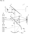
- the aerial image projector 1 may include a phase difference plate 7 as illustrated in, for example, FIG. 13 .
- the phase difference plate 7 is located between the second reflective element 3 and the first optical element 5.
- the phase difference plate 7 may be located on the optical paths of the first light L1 and the second light L2 between the second reflective element 3 and the first optical element 5.
- the phase difference plate 7 may rotate the polarization direction of the transmitted light.
- the first light L1 transmitted through the first reflective element 2 is polarized linearly or slightly elliptically along the transmission axis of the first reflective element 2.
- the first light L1 retroreflected by the second reflective element 3 or the second light L2 may be polarized linearly or slightly elliptically in the polarization direction of the first reflective element 2.
- the second light L2 incident on the first reflective element 2 without changing its polarization state may be polarized along the transmission axis of the first reflective element 2. This can increase the proportion of the second light L2 transmitted through the first reflective element 2.
- the phase difference plate 7 may be, for example, a quarter-wavelength plate.
- the first light L1 transmitted through the first reflective element 2 passes through the quarter-wavelength plate to be circularly polarized light that rotates in a first rotation direction.
- the first light L1 passing through the quarter-wavelength plate is retroreflected by the second reflective element 3 to be circularly-polarized second light L2 that rotates in a second rotation direction reverse to the first direction.
- the second light L2 retroreflected by the second reflective element 3 passes through the quarter-wavelength plate to be linearly polarized light traveling in the direction intersecting with the transmission axis of the first reflective element 2.
- the second light L2 is polarized linearly along the reflective axis of the first reflective element 2.
- the phase difference plate 7 that is a quarter-wavelength plate allows the second light L2 to be polarized linearly or slightly elliptically in the direction intersecting with the first light L1. This can increase the reflectance of the second light L2 from the first reflective element 2.
- the aerial image can thus have higher brightness.
- the structure may also reduce the light amount of the backlight 82 to reduce the power consumption of the aerial image projector 1.
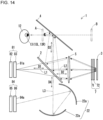
- the phase difference plate 7 may include a quarter-wavelength plate 71 and a half-wavelength plate 72 as illustrated in, for example, FIG. 14 .
- the half-wavelength plate 72 is located between the quarter-wavelength plate 71 and the second reflective element 3.
- the half-wavelength plate 72 may be located on the optical paths of the first light L1 and the second light L2 between the quarter-wavelength plate 71 and the second reflective element 3.
- Light passing through the quarter-wavelength plate 71 may rotate by a different degree depending on the wavelength.
- the light transmitted through the quarter-wavelength plate 71 is circularly polarized light that rotates in the first rotation direction in which the degree of rotation differs depending on the wavelength (right-handed circularly polarized light illustrated in FIGs. 15 and 16 ).
- the light transmitted through the quarter-wavelength plate 71 passes through the half-wavelength plate 72 to move to the opposite side of the Poincaré sphere to be circularly polarized light that rotates in the second rotation direction (left-handed circularly polarized light illustrated in FIGs. 15 and 16 ).
- the light passing through the half-wavelength plate 72 rotates by a degree that remains different depending on the wavelength.
- the light passing through the half-wavelength plate 72 is retroreflected by the second reflective element 3 to move to the opposite side of the Poincaré sphere to be the second light L2 being circularly polarized light that rotates in the first rotation direction.
- the second light L2 rotates by substantially the same degree as the degree by which the light rotates when the light is first transmitted through the quarter-wavelength plate 71.
- the second light L2 passes through the half-wavelength plate 72 to move to the opposite side of the Poincaré sphere to be circularly polarized light that rotates in the second rotation direction.
- the second light L2 rotates by substantially the same degree after passing through the half-wavelength plate 72 as the degree by which the first light L1 rotates after passing through the half-wavelength plate 72.
- the second light L2 transmitted through the quarter-wavelength plate 71 rotates by a different degree depending on the wavelength and is polarized in a direction orthogonal to the first light L1.
- the phase difference plate 7 including the quarter-wavelength plate 71 and the half-wavelength plate 72 causes S-polarized first light L1 to be incident on the second reflective element 3 and P-polarized second light L2 to be incident on the first reflective element 2 to reduce a loss caused by the degree of rotation in the polarization direction that depends on the wavelength.
- This structure uses a high reflectance near Brewster's angle for S polarization to increase the reflectance for the first light L1 on the second reflective element 3 and the second light L2 on the first reflective element 2.
- the aerial image can thus have higher brightness.
- the structure may also reduce the light amount of the backlight 85 to reduce the power consumption of the aerial image projector 1.
- the first display device 81 and the second display device 84 are, but not limited to, liquid crystal displays.
- the first display device 81 may be an LED display device, an OEL display device, or an OLED display device.
- the aerial image projector 1 may include a polarizing plate that linearly polarizes the first light L1 emitted from the first display device 81 in a predetermined direction.
- the second display device 84 may be an LED display device, an OEL display device, or an OLED display device.
- the aerial image projector 1 may include a polarizing plate that linearly polarizes the third light L3 emitted from the second display device 84 in a predetermined direction.
- a movable body according to one embodiment of the present disclosure will now be described with reference to FIG. 17 .
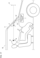
- the aerial image projector 1 according to the above embodiments may be mounted on a movable body 10 as illustrated in, for example, FIG. 17 .
- Examples of the movable body in the present disclosure include a vehicle, a vessel, and an aircraft.
- Examples of the vehicle include an automobile, an industrial vehicle, a railroad vehicle, a community vehicle, and a fixed-wing aircraft traveling on a runway.
- Examples of the automobile include a passenger vehicle, a truck, a bus, a motorcycle, and a trolley bus.
- Examples of the industrial vehicle include an industrial vehicle for agriculture and an industrial vehicle for construction.
- Examples of the industrial vehicle include a forklift and a golf cart.
- Examples of the industrial vehicle for agriculture include a tractor, a cultivator, a transplanter, a binder, a combine, and a lawn mower.
- Examples of the industrial vehicle for construction include a bulldozer, a scraper, a power shovel, a crane vehicle, a dump truck, and a road roller.
- Examples of the vehicle may include a human-powered vehicle. The classification of the vehicle is not limited to the above examples.
- Examples of the automobile include an industrial vehicle travelling on a road. One type of vehicle may fall within multiple classes.
- Examples of the vessel include a jet ski, a boat, and a tanker.
- Examples of the aircraft include a fixed-wing aircraft and a rotary-wing aircraft.
- the movable body 10 is a passenger vehicle.
- the movable body 10 may be any of the above examples in place of a passenger vehicle.
- the aerial image projector 1 may be at any position inside or outside the movable body 10.
- the aerial image projector 1 may be inside a dashboard in the movable body 10.
- the second light L2 reflected by the first reflective element 2 may be reflected by a windshield 11 as the third reflective element 4 and form an image in the air between the windshield 11 and the user 12.
- the third light L2 transmitted through the first reflective element 2 may be reflected by the windshield 11 as the third reflective element 4 and be incident on the left eye 13L and the right eye 13R of the user 12.
- the movable body 10 allows the user 12 to view both the aerial image A projected inside the movable body 10 and the aerial image B projected outside the movable body 10.
- the movable body 10 allows the user 12 to view aerial images A and B seamlessly extending from inside the movable body 10 to outside the movable body 10. This allows more information to be presented by the aerial image to the user 12.
- an aerial image projector includes a first reflective element, a second reflective element, a first optical element, a first display device, and a second display device.
- the first reflective element transmits, in a second direction, a part of first image light traveling in a first direction and representing an image, reflects, in a third direction, a part of second image light traveling in the second direction, and transmits, in the third direction, a part of third image light traveling in a fourth direction.
- the second reflective element retroreflects the first image light transmitted through the first reflective element as the second image light.
- the first optical element is between the first reflective element and the second reflective element and collects the first image light and the second image light.
- the first display device emits the first image light.
- the second display device emits the third image light.
- a movable body includes the aerial image projector.
- more information can be presented by an aerial image to a user.
- first, second, or others are identifiers for distinguishing the components.
- the identifiers of the components distinguished with first, second, and others in the present disclosure are interchangeable.
- the first reflective element can be interchangeable with the second reflective element.
- the identifiers are to be interchanged together.
- the components for which the identifiers are interchanged are also to be distinguished from one another.
- the identifiers may be eliminated.
- the components without such identifiers can be distinguished with reference numerals.
- the identifiers such as first and second in the present disclosure alone should not be used to determine the order of components or to suggest the existence of smaller number identifiers.
Landscapes
- Engineering & Computer Science (AREA)
- Physics & Mathematics (AREA)
- General Physics & Mathematics (AREA)
- Transportation (AREA)
- Mechanical Engineering (AREA)
- Chemical & Material Sciences (AREA)
- Combustion & Propulsion (AREA)
- Optics & Photonics (AREA)
- Multimedia (AREA)
- Signal Processing (AREA)
- Stereoscopic And Panoramic Photography (AREA)
- Lenses (AREA)
- Instrument Panels (AREA)
- Testing, Inspecting, Measuring Of Stereoscopic Televisions And Televisions (AREA)
- Optical Elements Other Than Lenses (AREA)
Abstract
Description
- The present disclosure relates to an aerial image projector and a movable body.
- A known technique is described in, for example,
Patent Literature 1. - Patent Literature 1:
Japanese Unexamined Patent Application Publication No. 2011-253128 - In an aspect of the present disclosure, an aerial image projector includes a first reflective element, a second reflective element, a first optical element, a first display device, and a second display device. The first reflective element transmits, in a second direction, a part of first image light traveling in a first direction and representing an image, reflects, in a third direction, a part of second image light traveling in the second direction, and transmits, in the third direction, a part of third image light traveling in a fourth direction. The second reflective element retroreflects the first image light transmitted through the first reflective element as the second image light. The first optical element is between the first reflective element and the second reflective element and collects the first image light and the second image light. The first display device emits the first image light. The second display device emits the third image light.
- In another aspect of the present disclosure, a movable body includes the aerial image projector.
- The objects, features, and advantages of the present disclosure will become more apparent from the following detailed description and the drawings.
-
FIG. 1 is a schematic diagram of an aerial image projector according to one embodiment of the present disclosure. -
FIG. 2 is a schematic diagram of the aerial image projector according to the embodiment of the present disclosure as viewed in a direction different from the direction inFIG. 1 . -
FIG. 3 is a schematic diagram of an aerial image projector according to a variation of the embodiment of the present disclosure. -
FIG. 4 is a schematic diagram of an aerial image projector according to another embodiment of the present disclosure. -
FIG. 5 is a schematic diagram of an aerial image projector according to another embodiment of the present disclosure. -
FIG. 6 is a schematic diagram of an aerial image projector according to another embodiment of the present disclosure. -
FIG. 7 is a schematic diagram of an aerial image projector according to another embodiment of the present disclosure. -
FIG. 8 is a schematic diagram of an aerial image projector according to another embodiment of the present disclosure. -
FIG. 9 is a schematic diagram of an aerial image projector according to another embodiment of the present disclosure. -
FIG. 10 is a schematic diagram of an aerial image projector according to another embodiment of the present disclosure. -
FIG. 11 is a schematic diagram of an aerial image projector according to another embodiment of the present disclosure. -
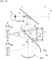
FIG. 12 is a schematic diagram of an aerial image projector according to another embodiment of the present disclosure. -
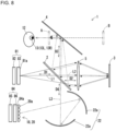
FIG. 13 is a schematic diagram of an aerial image projector according to another embodiment of the present disclosure. -
FIG. 14 is a schematic diagram of an aerial image projector according to another embodiment of the present disclosure. -
FIG. 15 is a diagram of the polarization states of first image light, second image light, and third image light. -
FIG. 16 is a diagram of the Poincaré sphere representing the polarization states of the first image light and the second image light. -
FIG. 17 is a schematic diagram of a movable body according to one embodiment of the present disclosure. - Various aerial image projectors have been developed to form an aerial image from image light emitted from a display.
- More information is to be presented by the aerial image to a user.
- One or more embodiments of the present disclosure will now be described with reference to the drawings. The drawings used herein are schematic. The drawings used herein are not drawn to scale relative to the actual size of each component and do not indicate the actual traveling path of light.
- As illustrated in, for example,
FIGs. 1 and2 , anaerial image projector 1 according to one embodiment of the present disclosure includes a firstreflective element 2, a secondreflective element 3, a firstoptical element 5, afirst display device 81, and asecond display device 84. - The
first display device 81 and thesecond display device 84 each emit image light representing an image. Thefirst display device 81 and thesecond display device 84 may each be a transmissive display device or a self-luminous display device. For example, the transmissive display device may be a liquid crystal display device. For example, the self-luminous display device may be a display device including a self-luminous element such as a light-emitting diode (LED) element, an organic electroluminescent (OEL) element, an organic LED (OLED) element, or a semiconductor laser diode (LD) element. In the example described below, both thefirst display device 81 and thesecond display device 84 are transmissive display devices. - The
first display device 81 includes adisplay surface 81a. Thefirst display device 81 emits image light through thedisplay surface 81a. As illustrated in, for example,FIGs. 1 and2 , thefirst display device 81 may be a liquid crystal display device including abacklight 82 and aliquid crystal panel 83. Theliquid crystal panel 83 may include thedisplay surface 81a. Thebacklight 82 may include multiple light sources that face thedisplay surface 81a and are arranged two-dimensionally adjacent to a back surface opposite to thedisplay surface 81a. The light sources may be, for example, LEDs, cold cathode fluorescent lamps, halogen lamps, or xenon lamps. Thebacklight 82 including light sources that face thedisplay surface 81a and are arranged adjacent to the back surface opposite to thedisplay surface 81a can be referred to as a direct backlight. Thebacklight 82 may include multiple light sources arranged on the outer periphery of theliquid crystal panel 83 to guide light to the entire back surface opposite to thedisplay surface 81a using a light guide plate. Thebacklight 82 including the light sources arranged on the outer periphery of theliquid crystal panel 83 can be referred to as an edge backlight. Thebacklight 82 may include, for example, a lens array, a light guide plate, and a diffusion plate to apply light from the light sources uniformly onto thedisplay surface 81a. - The
liquid crystal panel 83 may have the structure of a known liquid crystal panel. The known liquid crystal panel herein may be an in-plane switching (IPS) panel, a fringe field switching (FFS) panel, a vertical alignment (VA) panel, an electrically controlled birefringence (ECB) panel, or any of various other liquid crystal panels. Theliquid crystal panel 83 may include a display-surface polarizing plate, a color filter substrate, a liquid crystal layer, an array substrate, and a back-surface polarizing plate. The display-surface polarizing plate may be closer to thedisplay surface 81a than the color filter substrate, the liquid crystal layer, the array substrate, and the back-surface polarizing plate. The image light emitted from thefirst display device 81 may be linearly polarized in the polarization direction of the display-surface polarizing plate in theliquid crystal panel 83. - The
second display device 84 includes a display surface 82a. Thesecond display device 84 emits image light through the display surface 82a. As illustrated in, for example,FIGs. 1 and2 , thesecond display device 84 may be a liquid crystal display device including abacklight 85 and aliquid crystal panel 86. Theliquid crystal panel 86 may include the display surface 82a. Thebacklight 85 may include multiple light sources that face the display surface 82a and are arranged two-dimensionally adjacent to a back surface opposite to the display surface 82a. The light sources may be, for example, LEDs, cold cathode fluorescent lamps, halogen lamps, or xenon lamps. Thebacklight 85 may be a direct backlight or an edge backlight. Thebacklight 85 may include, for example, a lens array, a light guide plate, and a diffusion plate to apply light from the light sources uniformly onto the display surface 82a. - The
liquid crystal panel 86 may have the structure of a known liquid crystal panel. The known liquid crystal panel herein may be an IPS panel, an FFS panel, a VA panel, an ECB panel, or any of various other liquid crystal panels. Theliquid crystal panel 86 may include a display-surface polarizing plate, a color filter substrate, a liquid crystal layer, an array substrate, and a back-surface polarizing plate. The display-surface polarizing plate may be closer to the display surface 82a than the color filter substrate, the liquid crystal layer, the array substrate, and the back-surface polarizing plate. The image light emitted from thesecond display device 84 may be linearly polarized in the polarization direction of the display-surface polarizing plate in theliquid crystal panel 86. - As illustrated in, for example,
FIGs. 1 and2 , the firstreflective element 2 transmits, in a second direction D2, a part of first image light (hereafter referred to as first light) L1 traveling in a first direction D1. The first light L1 represents an image. The firstreflective element 2 may reflect the remaining part of the first light L1. As illustrated in, for example,FIGs. 1 and2 , the firstreflective element 2 reflects, in a third direction D3, a part of second image light (hereafter referred to as second light) L2 traveling in the second direction D2. The second light L2 represents an image. The firstreflective element 2 may transmit the remaining part of the second light L2. As illustrated in, for example,FIGs. 1 and2 , the firstreflective element 2 transmits, in the third direction D3, a part of third image light (hereafter referred to as third light) L3 traveling in a fourth direction D4. The third light L3 represents an image. The firstreflective element 2 may reflect the remaining part of the third light L3. The third direction D3 and the fourth direction D4 may be parallel or substantially parallel to each other, or may be different directions. - The first light L1 is image light emitted from the
first display device 81. The second light L2 is reflected light that is the part of the first light L1 transmitted through the firstreflective element 2 and retroreflected by the secondreflective element 3. The third light L3 is image light emitted from thesecond display device 84. - The first light L1 may be parallel light traveling in the first direction D1 or light traveling in a direction substantially parallel to the first direction D1. The first light L1 may be light traveling mainly in the
first direction D 1. - The second light L2 may be parallel light traveling in the second direction D2 or light traveling in a direction substantially parallel to the second direction D2. The second light L2 may be light traveling mainly in the second direction D2. The first
reflective element 2 may reflect a part of the second light L2 as parallel light traveling in the third direction D3 or reflect a part of the second light L2 as light traveling in a direction substantially parallel to the third direction D3. The firstreflective element 2 may reflect a part of the second light L2 as light traveling mainly in the third direction D3. - The third light L3 may be parallel light traveling in the fourth direction D4 or light traveling in a direction substantially parallel to the fourth direction D4. The third light L3 may be light traveling mainly in the fourth direction D4. The first
reflective element 2 may transmit a part of the third light L3 as parallel light traveling in the third direction D3 or transmit a part of the third light L3 as light traveling in a direction substantially parallel to the third direction D3. The firstreflective element 2 may transmit a part of the third light L3 as light traveling mainly in the third direction D3. - As described above, the traveling direction of light herein refers to a substantial traveling direction of light. The traveling direction of light herein also refers to the main traveling direction of light.
- The
first display device 81 may direct the first light L1 toward the firstreflective element 2 in the first direction D1. Thesecond display device 84 may direct the third light L3 toward the firstreflective element 2 in the fourth direction D4. - The
second display device 84 may not direct the third light L3 toward the firstreflective element 2 in the fourth direction D4. In this case, theaerial image projector 1 may include anoptical system 22 that directs the third light L3 emitted from thesecond display device 84 to travel in the fourth direction D4 and to be incident on the firstreflective element 2, as illustrated in, for example,FIGs. 1 and2 . Theoptical system 22 may include at least onereflector 22a. Thereflector 22a may include a concave mirror or a freeformed mirror. Thereflector 22a is not limited to a concave mirror or a freeformed mirror, and may include a reflector such as a plane mirror or a convex mirror. Theoptical system 22 may include a refractor such as a lens. Theoptical system 22 may include an optical member such as a phase difference plate and a polarizer other than a reflector and a refractor. - The first
reflective element 2 may be, for example, a reflective polarizer, a semitransparent mirror, or a beam splitter. The reflective polarizer may be a wire-grid polarizer including a light transmissive substrate and multiple metal wires on a surface of the light transmissive substrate. The light transmissive substrate may be, for example, a triacetyl cellulose (TAC) film, a polyethylene terephthalate (PET) film, or a cycloolefin polymer (COP) film. The metal wires may be made of, for example, a metal material such as aluminum, chromium, or titanium oxide. For the firstreflective element 2 being a reflective polarizer in the present embodiment, the first light L1 transmitted through the firstreflective element 2 is polarized linearly or slightly elliptically along the transmission axis of the firstreflective element 2. - The second
reflective element 3 retroreflects the first light L1 transmitted through the firstreflective element 2 as the second light L2. In other words, the second light L2 is reflected light that is the first light L1 transmitted through the firstreflective element 2 and retroreflected by the secondreflective element 3. The secondreflective element 3 may be located apart from the firstreflective element 2 in the second direction D2. - The second
reflective element 3 may be a retroreflective element, which is also referred to as a retroreflector. The secondreflective element 3 may be, for example, a corner cube retroreflective element or a microbead retroreflective element. - The first
optical element 5 is located between the firstreflective element 2 and the secondreflective element 3 as illustrated in, for example,FIGs. 1 and2 . The firstoptical element 5 may be located on the optical paths of the first light L1 and the second light L2 between the firstreflective element 2 and the secondreflective element 3. - The first
optical element 5 collects light. The firstoptical element 5 collects the first light L1 transmitted through the firstreflective element 2. The firstoptical element 5 collects the second light L2 retroreflected by the secondreflective element 3. The firstoptical element 5 may include, for example, one or more lenses or one or more mirrors. - The first
optical element 5 may be a biconvex lens as illustrated in, for example,FIGs. 1 and2 . The lens surface of the biconvex lens may be at least partially spherical or at least partially aspherical. The lens surface of the biconvex lens may be at least partially freeformed. - The first
optical element 5 may be a Fresnel lens. The firstoptical element 5 can thus be thinner. Theaerial image projector 1 can thus be compact. The Fresnel lens may include refractive portions being at least partially spherical or at least partially aspherical. Each refractive portion of the Fresnel lens may be at least partially freeformed. - The first
optical element 5 may be a liquid crystal lens or a liquid lens. The liquid crystal lens or the liquid lens may change its focus or its focal point. The firstoptical element 5 can thus change the focus or the focal point based on, for example, the relative positions of the firstreflective element 2 and the secondreflective element 3. Thus, theaerial image projector 1 has higher flexibility in positioning its components. - The first
optical element 5 being a lens may include, on a part of or a full portion of its lens surface, an anti-reflection (AR) coating layer that reduces reflection of the first light L1 and the second light L2. Thus, theaerial image projector 1 has higher light utilization. - Referring to
FIGs. 1 and2 , the formation of an aerial image performed by theaerial image projector 1 will be described. The first light L1 emitted from thefirst display device 81 travels in the first direction D1 and reaches the firstreflective element 2. Apart of the first light L1 reaching the firstreflective element 2 is transmitted through the firstreflective element 2 and travels in the second direction D2. The first light L1 transmitted through the firstreflective element 2 is collected by the firstoptical element 5 and reaches the secondreflective element 3. The first light L1 reaching the secondreflective element 3 is retroreflected by the secondreflective element 3 to be the second light L2. The second light L2 is collected by the firstoptical element 5 and reaches the firstreflective element 2. A part of the second light L2 reaching the firstreflective element 2 is reflected by the firstreflective element 2 in the third direction D3. The second light L2 reflected by the firstreflective element 2 forms an image in the air and is viewed by auser 12 as an aerial image A that is a real image. - The
aerial image projector 1 may include a thirdreflective element 4 as illustrated in, for example,FIGs. 1 and2 . The thirdreflective element 4 may reflect a part of the third light L3 transmitted through the firstreflective element 2 toward aleft eye 13L and aright eye 13R of theuser 12. Theleft eye 13L and theright eye 13R may be collectively referred to aseyes 13. The thirdreflective element 4 may be a mirror including, for example, glass or a light reflective resin. When theaerial image projector 1 is mounted on a movable body including a windshield, the windshield may serve as the thirdreflective element 4. The second light L2 may form an image between the thirdreflective element 4 and theeyes 13 of theuser 12. - When light to be retroreflected by a retroreflective element is incident on a wide area of a reflective surface of the retroreflective element, the light may be affected by the size of a prism included in the retroreflective element and diffraction by the prism. In this case, the retroreflected light may diffuse to form a blurry aerial image. The diffraction by the prism included in the retroreflective element affects the light more noticeably when the distance between the display device and the retroreflective element is longer. The
aerial image projector 1 includes the firstoptical element 5 that collects light between thefirst display device 81 and the secondreflective element 3. In this case, the light collected by the firstoptical element 5 is incident on a relatively narrow area of a reflective surface of the secondreflective element 3, thus reducing diffusion of the second light L2 retroreflected by the secondreflective element 3. This thus increases the resolution of the aerial image A, allowing more information to be presented by the aerial image to the user. - As illustrated in, for example,
FIG. 1 , the third light L3 emitted from thesecond display device 84 travels in the fourth direction D4 and reaches the firstreflective element 2. Apart of the third light L3 reaching the firstreflective element 2 is transmitted through the firstreflective element 2 and travels in the third direction D3. The third light L3 transmitted through the firstreflective element 2 is incident on theeyes 13 of theuser 12 and is viewed by theuser 12 as an aerial image B that is a virtual image. Theaerial image projector 1 may allow the thirdreflective element 4 to reflect the third light L3 transmitted through the firstreflective element 2 to be incident on theeyes 13 of theuser 12. - The
aerial image projector 1 according to the present embodiment allows theuser 12 to view both the aerial image A, which is a projected image of the first light L1 emitted from thefirst display device 81, and the aerial image B, which is a projected image of the third light L3 emitted from thesecond display device 84. This allows more information to be presented by the aerial image to theuser 12. - When the
aerial image projector 1 is mounted on a movable body including a windshield serving as the thirdreflective element 4, the aerial image A is projected inside the movable body, and the aerial image B is projected outside the movable body. In other words, theaerial image projector 1 allows theuser 12 to view an aerial image seamlessly extending from inside the movable body to outside the movable body. - The
aerial image projector 1 allows both the second light L2 reflected by the firstreflective element 2 and the third light L3 transmitted through the firstreflective element 2 to travel in the third direction D3. Theaerial image projector 1 thus allows the user to view both the aerial image A and the aerial image B using a reflective element with a simple structure, for example, the windshield serving as the thirdreflective element 4. - In the
aerial image projector 1, the first light L1 reaching the firstreflective element 2 may be polarized in the polarization direction of the firstreflective element 2. In other words, theaerial image projector 1 may polarize the first light L1 reaching the firstreflective element 2 in a direction parallel to the transmission axis of the firstreflective element 2. For the firstreflective element 2 being a reflective polarizer, the first light L1 polarized along the transmission axis of the firstreflective element 2 reduces reflection of the first light L1 from the firstreflective element 2. This can thus increase the light utilization of theaerial image projector 1 and increase the brightness of the aerial image A. The structure may also reduce the light amount of thebacklight 82 to reduce the power consumption of theaerial image projector 1. - The
aerial image projector 1 may adjust the polarization direction of the first light L1 emitted from thefirst display device 81 to allow the first light L1 reaching the firstreflective element 2 to be polarized in the direction parallel to the transmission axis of the firstreflective element 2. Theaerial image projector 1 may adjust the polarization direction of the display-surface polarizing plate in theliquid crystal panel 83 to allow the first light L1 reaching the firstreflective element 2 to be polarized in the direction parallel to the transmission axis of the firstreflective element 2. In some embodiments, theaerial image projector 1 may include an optical member between thefirst display device 81 and the firstreflective element 2 to polarize the first light L1 in the direction parallel to the transmission axis of the firstreflective element 2. - In the
aerial image projector 1, the third light L3 reaching the firstreflective element 2 may be polarized in the polarization direction of the firstreflective element 2. In other words, theaerial image projector 1 may allow the third light L3 reaching the firstreflective element 2 to be polarized in the direction parallel to the transmission axis of the firstreflective element 2. For the firstreflective element 2 being a reflective polarizer, the third light L3 polarized along the transmission axis of the firstreflective element 2 reduces reflection of the third light L3 from the firstreflective element 2. This can thus increase the light utilization of theaerial image projector 1 and increase the brightness of the aerial image B. The structure may also reduce the light amount of thebacklight 85 to reduce the power consumption of theaerial image projector 1. - The
aerial image projector 1 may adjust the polarization direction of the third light L3 emitted from thesecond display device 84 to allow the third light L3 reaching the firstreflective element 2 to be polarized in the direction parallel to the transmission axis of the firstreflective element 2. Theaerial image projector 1 may adjust the polarization direction of the display-surface polarizing plate in theliquid crystal panel 86 to allow the third light L3 reaching the firstreflective element 2 to be polarized in the direction parallel to the transmission axis of the firstreflective element 2. In some embodiments, theaerial image projector 1 may include an optical member to allow theoptical system 22 between thesecond display device 84 and the firstreflective element 2 to polarize the third light L3 in the direction parallel to the transmission axis of the firstreflective element 2. - The
aerial image projector 1 may include the secondreflective element 3 adjacent to the focal point of the firstoptical element 5. This structure allows the first light L1 collected by the firstoptical element 5 to be incident on a narrow area of the reflective surface of the secondreflective element 3. This thus reduces diffusion of the second light L2, and increases the resolution of the aerial image A and the amount of information presented by the aerial image to theuser 12. - The
aerial image projector 1 may include thefirst display device 81 adjacent to the focal point of the firstoptical element 5 and the secondreflective element 3 adjacent to the focal point of the firstoptical element 5. More specifically, theaerial image projector 1 may include thefirst display device 81 and the secondreflective element 3 to be optically conjugated with each other. This allows an aerial image with high resolution to be projected at varying positions in the air by simply translating or rotating the firstoptical element 5. - The
aerial image projector 1 may include a camera 9 as illustrated in, for example,FIG. 3 . The camera 9 may be a visible light camera or an infrared camera. The infrared light camera may be a far-infrared camera. The camera 9 may capture a visible light image and an infrared light image. The camera 9 may be a monocular camera or a stereo camera. The camera 9 may include, for example, a charge-coupled device (CCD) image sensor or a complementary metal-oxide semiconductor (CMOS) image sensor. - The camera 9 may capture an image of the
user 12. The camera 9 may capture an image of the face of theuser 12. The camera 9 may capture an image of theeyes 13 of theuser 12. The camera 9 may capture an image of at least one of theleft eye 13L or theright eye 13R of theuser 12. Theaerial image projector 1 may detect the positions of theleft eye 13L and theright eye 13R based on the captured image. Theaerial image projector 1 may adjust, for example, the projection positions and the brightness of the aerial images A and B based on the detected positions of theleft eye 13L and theright eye 13R. This allows theuser 12 at various positions to view the aerial images A and B. The camera 9 may capture an image of feature points included in the face of theuser 12 for identifying the position of at least one of theleft eye 13L or theright eye 13R, rather than capturing the image of theeyes 13 of theuser 12. The feature points may include the eyebrows, nose, and lips of theuser 12. - As illustrated in, for example,
FIG. 3 , the camera 9 may capture an image of an area in the third direction D3 through the firstreflective element 2. The camera 9 may capture an image of theuser 12 through the firstreflective element 2. The camera 9 may capture an image of theuser 12 reflected by the thirdreflective element 4 through the firstreflective element 2. This structure can increase the positioning flexibility of the camera 9. - The
aerial image projector 1 may include no camera 9 and may be connected to an external camera (not illustrated) external to the projector. Theaerial image projector 1 may include an input terminal for receiving signals from the external camera. The external camera may be connected to the input terminal directly. The external camera may be connected to the input terminal indirectly through a shared network. - The
aerial image projector 1 may include a controller (not illustrated). The controller is connected to the components of theaerial image projector 1 and controls the components. The controller may be, for example, a processor. The controller may include one or more processors. The processors may include a general-purpose processor that reads a specific program to perform a specific function, and a processor dedicated to specific processing. The dedicated processor may include an application-specific integrated circuit (ASIC). The processor may include a programmable logic device (PLD). The PLD may include a field-programmable gate array (FPGA). The controller may be either a system on a chip (SoC) or a system in a package (SiP) in which one or more processors cooperate with other components. - An aerial image projector according to another embodiment of the present disclosure will now be described with reference to
FIGs. 4 to 14 . - The
first display device 81 may display, on thedisplay surface 81a, a first composite image including first left-eye images viewable by theleft eye 13L of theuser 12 and first right-eye images viewable by theright eye 13R of theuser 12. The first right-eye image has parallax with the first left-eye image. The first light L1 may be image light representing the first composite image including the first left-eye images and the first right-eye images. - The
aerial image projector 1 may include a third optical element 14 as illustrated in, for example,FIGs. 4 to 6 . The third optical element 14 may divide the first light L1 representing the first composite image into first left-eye image light representing the first left-eye image and first right-eye image light representing the first right-eye image light. The third optical element 14 may be located between thebacklight 82 and theliquid crystal panel 83 or in front of thedisplay surface 81a (specifically, downstream from theliquid crystal panel 83 in the travel direction of the first light L1) as illustrated in, for example,FIG. 4 . - The third optical element 14 may include a parallax barrier 15 as illustrated in, for example,
FIG. 4 . The parallax barrier 15 includes multiple light-blockingportions 15a. The light-blockingportions 15a block the image light emitted from thefirst display device 81. The light-blockingportions 15a defineopen areas 15b between adjacent light-blockingportions 15a. Theopen areas 15b have a higher light transmittance than the light-blockingportions 15a. In other words, the light-blockingportions 15a have a lower light transmittance than theopen areas 15b. - The
open areas 15b are parts of the parallax barrier 15 to transmit light incident on the parallax barrier 15. Theopen areas 15b may transmit light with a transmittance of a first predetermined value or greater. The first predetermined value may be, for example, 100% or a value close to 100%. The light-blockingportions 15a are parts of the parallax barrier 15 to block light incident on the parallax barrier 15. In other words, the light-blockingportions 15a block an image displayed by thefirst display device 81. The light-blockingportions 15a may block light with a transmittance of a second predetermined value or less. The second predetermined value may be, for example, 0% or a value close to 0%. The ratio of the second predetermined value to the first predetermined value may be 1/100 or 1/1000. - The parallax barrier 15 may be a film or a plate with a transmittance less than the second predetermined value. In this case, the light-blocking
portions 15a are parts of the film or plate. Theopen areas 15b are slits in the film or plate. The film may be made of a resin or another material. The plate may be made of a resin, metal, or another material. The parallax barrier 15 may be a member other than a film or a plate. The parallax barrier 15 may include a base made of a light-blocking material or of a material containing an additive with light-blocking properties. - The parallax barrier 15 may be, for example, a liquid crystal shutter. The liquid crystal shutter can control the light transmittance in response to a voltage applied. The liquid crystal shutter may include multiple pixels and control the transmittance of light for each pixel. The liquid crystal shutter can form a portion with a high light transmittance or a portion with a low light transmittance in an intended shape. For the parallax barrier 15 being a liquid crystal shutter, the
open areas 15b may have a transmittance of the first predetermined value or greater. For the parallax barrier 15 being a liquid crystal shutter, the light-blockingportions 15a may have a transmittance of the second predetermined value or less. - The
aerial image projector 1 illustrated inFIG. 4 allows theuser 12 to three-dimensionally view the aerial image A that is a real image by observing a projected image formed by the first left-eye image light with theleft eye 13L and a projected image formed by the first right-eye image light with theright eye 13R. - The third optical element 14 is not limited to the parallax barrier 15. The third optical element 14 may include a lenticular lens 16 as illustrated in, for example,
FIG. 5 . The lenticular lens 16 may include, for example, multiplesemicylindrical lenses 16a that extend in a predetermined direction and are arranged in a direction orthogonal to the predetermined direction. Theaerial image projector 1 including the third optical element 14 including the lenticular lens 16 allows theuser 12 to three-dimensionally view the aerial image A. - The third optical element 14 is not limited to the parallax barrier 15 and the lenticular lens 16. The third optical element 14 may include a microlens array 17 as illustrated in, for example,
FIG. 6 . The microlens array 17 includes, for example,multiple microlenses 17a arranged in a matrix. Each of themicrolenses 17a may be, for example, a biconvex lens, a plano-convex lens, or a meniscus lens. Theaerial image projector 1 including the third optical element 14 including the microlens array 17 allows theuser 12 to three-dimensionally view the aerial image A. - The
second display device 84 may display, on the display surface 82a, a second composite image including second left-eye images viewable by theleft eye 13L of theuser 12 and second right-eye images viewable by theright eye 13R of theuser 12. The second right-eye image has parallax with the second left-eye image. The third light L3 may be image light representing the second composite image including the second left-eye images and the second right-eye images. - The
aerial image projector 1 may include a fourth optical element 18 as illustrated in, for example,FIGs. 7 to 9 . The fourth optical element 18 may divide the third light L3 representing the second composite image into second left-eye image light representing the second left-eye image and second right-eye image light representing the second right-eye image. The fourth optical element 18 may be located between thebacklight 85 and theliquid crystal panel 86 or in front of the display surface 82a (specifically, downstream from theliquid crystal panel 86 in the travel direction of the third light L3) as illustrated in, for example,FIG. 7 . - The fourth optical element 18 may include a parallax barrier 19 including multiple light-blocking
portions 19a as illustrated in, for example,FIG. 7 . The light-blockingportions 19a defineopen areas 19b between adjacent light-blockingportions 19a. The parallax barrier 19 has the structure similar to the structure of the parallax barrier 15, and the structure will not be described in detail. - The
aerial image projector 1 illustrated inFIG. 7 allows theuser 12 to three-dimensionally view the aerial image B that is a virtual image by observing the second left-eye image light with theleft eye 13L and the second right-eye image light with theright eye 13R. - The fourth optical element 18 is not limited to the parallax barrier 19. As illustrated in
FIG. 8 , the fourth optical element 18 may include a lenticular lens 20 including multiplesemicylindrical lenses 20a. The lenticular lens 20 has the structure similar to the structure of the lenticular lens 16, and the structure will not be described in detail. Theaerial image projector 1 including the fourth optical element 18 including the lenticular lens 20 allows theuser 12 to three-dimensionally view the aerial image B. - The fourth optical element 18 is not limited to the parallax barrier 19 and the lenticular lens 20. The fourth optical element 18 may include a microlens array 21 including
multiple microlenses 21a as illustrated inFIG. 9 . The microlens array 21 has the structure similar to the structure of the microlens array 17, and the structure will not be described in detail. Theaerial image projector 1 including the fourth optical element 18 including the microlens array 21 allows theuser 12 to three-dimensionally view the aerial image B. - Either the aerial image A or the aerial image B is not limited to a stereoscopic image as in the above embodiments. In the
aerial image projector 1, both the aerial image A and the aerial image B may be stereoscopic images. The term stereoscopic image herein refers to an image three-dimensionally viewable by theuser 12. - The first
optical element 5 may include amicrolens array 51 as illustrated in, for example,FIG. 10 . Themicrolens array 51 is an optical element includingmultiple microlenses 51a arrayed on a substrate. Themicrolenses 51a may be circular, rectangular, or polygonal as viewed in a direction orthogonal to the main surface of the substrate. Themicrolenses 51a may be arranged regularly (specifically, in a matrix) or randomly. The lens surface of eachmicrolens 51a may be at least partially spherical or at least partially aspherical. The lens surface of eachmicrolens 51a may be at least partially freeformed. For the firstoptical element 5 being themicrolens array 51, the arrangement of themicrolenses 51a and the shape and size of eachmicrolens 51a can be adjusted to finely control the distribution of the first light L1 and the second light L2. This thus increases the resolution of the aerial image A, allowing more information to be presented by the aerial image to theuser 12. - The first
optical element 5 may include aconcave mirror 52 as illustrated in, for example,FIG. 11 . Areflective surface 52a of theconcave mirror 52 may be at least partially spherical or at least partially aspherical. Thereflective surface 52a may be at least partially freeformed. For the firstoptical element 5 being theconcave mirror 52, theaerial image projector 1 with the simple structure can increase the resolution of the aerial image A. This allows more information to be presented by the aerial image to theuser 12. - The
aerial image projector 1 may include a second optical element 6 as illustrated in, for example,FIG. 12 . The second optical element 6 may be located between the secondreflective element 3 and the firstoptical element 5. The second optical element 6 may be located adjacent to the reflective surface of the secondreflective element 3. The second optical element 6 may collect scattering light included in the second light L2. This reduces diffusion of the second light L2 retroreflected by the secondreflective element 3. This thus increases the resolution of the aerial image A, allowing more information to be presented by the aerial image to theuser 12. - The second optical element 6 may be, for example, a plano-convex lens, a biconvex lens, a meniscus lens, or a Fresnel lens. The second optical element 6 may include one or more lenses. The second optical element 6 may be, for example, a microlens array.
- The
aerial image projector 1 may include aphase difference plate 7 as illustrated in, for example,FIG. 13 . Thephase difference plate 7 is located between the secondreflective element 3 and the firstoptical element 5. Thephase difference plate 7 may be located on the optical paths of the first light L1 and the second light L2 between the secondreflective element 3 and the firstoptical element 5. Thephase difference plate 7 may rotate the polarization direction of the transmitted light. - For the first
reflective element 2 being a reflective polarizer, the first light L1 transmitted through the firstreflective element 2 is polarized linearly or slightly elliptically along the transmission axis of the firstreflective element 2. The first light L1 retroreflected by the secondreflective element 3 or the second light L2 may be polarized linearly or slightly elliptically in the polarization direction of the firstreflective element 2. Thus, the second light L2 incident on the firstreflective element 2 without changing its polarization state may be polarized along the transmission axis of the firstreflective element 2. This can increase the proportion of the second light L2 transmitted through the firstreflective element 2. - The
phase difference plate 7 may be, for example, a quarter-wavelength plate. The first light L1 transmitted through the firstreflective element 2 passes through the quarter-wavelength plate to be circularly polarized light that rotates in a first rotation direction. The first light L1 passing through the quarter-wavelength plate is retroreflected by the secondreflective element 3 to be circularly-polarized second light L2 that rotates in a second rotation direction reverse to the first direction. The second light L2 retroreflected by the secondreflective element 3 passes through the quarter-wavelength plate to be linearly polarized light traveling in the direction intersecting with the transmission axis of the firstreflective element 2. In other words, the second light L2 is polarized linearly along the reflective axis of the firstreflective element 2. Thephase difference plate 7 that is a quarter-wavelength plate allows the second light L2 to be polarized linearly or slightly elliptically in the direction intersecting with the first light L1. This can increase the reflectance of the second light L2 from the firstreflective element 2. The aerial image can thus have higher brightness. The structure may also reduce the light amount of thebacklight 82 to reduce the power consumption of theaerial image projector 1. - The
phase difference plate 7 may include a quarter-wavelength plate 71 and a half-wavelength plate 72 as illustrated in, for example,FIG. 14 . The half-wavelength plate 72 is located between the quarter-wavelength plate 71 and the secondreflective element 3. The half-wavelength plate 72 may be located on the optical paths of the first light L1 and the second light L2 between the quarter-wavelength plate 71 and the secondreflective element 3. - Light passing through the quarter-
wavelength plate 71 may rotate by a different degree depending on the wavelength. The light transmitted through the quarter-wavelength plate 71 is circularly polarized light that rotates in the first rotation direction in which the degree of rotation differs depending on the wavelength (right-handed circularly polarized light illustrated inFIGs. 15 and16 ). As illustrated inFIGs. 15 and16 , the light transmitted through the quarter-wavelength plate 71 passes through the half-wavelength plate 72 to move to the opposite side of the Poincaré sphere to be circularly polarized light that rotates in the second rotation direction (left-handed circularly polarized light illustrated inFIGs. 15 and16 ). The light passing through the half-wavelength plate 72 rotates by a degree that remains different depending on the wavelength. As illustrated inFIGs. 15 and16 , the light passing through the half-wavelength plate 72 is retroreflected by the secondreflective element 3 to move to the opposite side of the Poincaré sphere to be the second light L2 being circularly polarized light that rotates in the first rotation direction. The second light L2 rotates by substantially the same degree as the degree by which the light rotates when the light is first transmitted through the quarter-wavelength plate 71. As illustrated inFIGs. 15 and16 , the second light L2 passes through the half-wavelength plate 72 to move to the opposite side of the Poincaré sphere to be circularly polarized light that rotates in the second rotation direction. The second light L2 rotates by substantially the same degree after passing through the half-wavelength plate 72 as the degree by which the first light L1 rotates after passing through the half-wavelength plate 72. The second light L2 transmitted through the quarter-wavelength plate 71 rotates by a different degree depending on the wavelength and is polarized in a direction orthogonal to the first light L1. - The
phase difference plate 7 including the quarter-wavelength plate 71 and the half-wavelength plate 72 causes S-polarized first light L1 to be incident on the secondreflective element 3 and P-polarized second light L2 to be incident on the firstreflective element 2 to reduce a loss caused by the degree of rotation in the polarization direction that depends on the wavelength. This structure uses a high reflectance near Brewster's angle for S polarization to increase the reflectance for the first light L1 on the secondreflective element 3 and the second light L2 on the firstreflective element 2. The aerial image can thus have higher brightness. The structure may also reduce the light amount of thebacklight 85 to reduce the power consumption of theaerial image projector 1. - In the above embodiments, the
first display device 81 and thesecond display device 84 are, but not limited to, liquid crystal displays. Thefirst display device 81 may be an LED display device, an OEL display device, or an OLED display device. Theaerial image projector 1 may include a polarizing plate that linearly polarizes the first light L1 emitted from thefirst display device 81 in a predetermined direction. Thesecond display device 84 may be an LED display device, an OEL display device, or an OLED display device. Theaerial image projector 1 may include a polarizing plate that linearly polarizes the third light L3 emitted from thesecond display device 84 in a predetermined direction. - A movable body according to one embodiment of the present disclosure will now be described with reference to
FIG. 17 . Theaerial image projector 1 according to the above embodiments may be mounted on amovable body 10 as illustrated in, for example,FIG. 17 . - Examples of the movable body in the present disclosure include a vehicle, a vessel, and an aircraft. Examples of the vehicle include an automobile, an industrial vehicle, a railroad vehicle, a community vehicle, and a fixed-wing aircraft traveling on a runway. Examples of the automobile include a passenger vehicle, a truck, a bus, a motorcycle, and a trolley bus. Examples of the industrial vehicle include an industrial vehicle for agriculture and an industrial vehicle for construction. Examples of the industrial vehicle include a forklift and a golf cart. Examples of the industrial vehicle for agriculture include a tractor, a cultivator, a transplanter, a binder, a combine, and a lawn mower. Examples of the industrial vehicle for construction include a bulldozer, a scraper, a power shovel, a crane vehicle, a dump truck, and a road roller. Examples of the vehicle may include a human-powered vehicle. The classification of the vehicle is not limited to the above examples. Examples of the automobile include an industrial vehicle travelling on a road. One type of vehicle may fall within multiple classes. Examples of the vessel include a jet ski, a boat, and a tanker. Examples of the aircraft include a fixed-wing aircraft and a rotary-wing aircraft.
- In the example of
FIG. 17 , themovable body 10 is a passenger vehicle. Themovable body 10 may be any of the above examples in place of a passenger vehicle. Theaerial image projector 1 may be at any position inside or outside themovable body 10. For example, theaerial image projector 1 may be inside a dashboard in themovable body 10. - In the
aerial image projector 1, the second light L2 reflected by the firstreflective element 2 may be reflected by awindshield 11 as the thirdreflective element 4 and form an image in the air between thewindshield 11 and theuser 12. This allows theuser 12 to view the aerial image A that is a real image projected inside themovable body 10. In theaerial image projector 1, the third light L2 transmitted through the firstreflective element 2 may be reflected by thewindshield 11 as the thirdreflective element 4 and be incident on theleft eye 13L and theright eye 13R of theuser 12. This allows theuser 12 to view the aerial image B that is a virtual image projected outside themovable body 10. Thus, themovable body 10 allows theuser 12 to view both the aerial image A projected inside themovable body 10 and the aerial image B projected outside themovable body 10. In other words, themovable body 10 allows theuser 12 to view aerial images A and B seamlessly extending from inside themovable body 10 to outside themovable body 10. This allows more information to be presented by the aerial image to theuser 12. - The present disclosure may be implemented in the following forms.
- In one or more embodiments of the present disclosure, an aerial image projector includes a first reflective element, a second reflective element, a first optical element, a first display device, and a second display device. The first reflective element transmits, in a second direction, a part of first image light traveling in a first direction and representing an image, reflects, in a third direction, a part of second image light traveling in the second direction, and transmits, in the third direction, a part of third image light traveling in a fourth direction. The second reflective element retroreflects the first image light transmitted through the first reflective element as the second image light. The first optical element is between the first reflective element and the second reflective element and collects the first image light and the second image light. The first display device emits the first image light. The second display device emits the third image light.
- In one or more embodiments of the present disclosure, a movable body includes the aerial image projector.
- In one embodiment of the present disclosure, more information can be presented by an aerial image to a user.
- In the present disclosure, first, second, or others are identifiers for distinguishing the components. The identifiers of the components distinguished with first, second, and others in the present disclosure are interchangeable. For example, the first reflective element can be interchangeable with the second reflective element. The identifiers are to be interchanged together. The components for which the identifiers are interchanged are also to be distinguished from one another. The identifiers may be eliminated. The components without such identifiers can be distinguished with reference numerals. The identifiers such as first and second in the present disclosure alone should not be used to determine the order of components or to suggest the existence of smaller number identifiers.
- Although embodiments of the present disclosure have been described in detail, the present disclosure is not limited to the embodiments described above, and may be changed or varied in various manners without departing from the spirit and scope of the present disclosure. The components described in the above embodiments may be entirely or partially combined as appropriate unless any contradiction arises.
-
- 1
- aerial image projector
- 2
- first reflective element
- 3
- second reflective element
- 4
- third reflective element
- 5
- first optical element
- 6
- second optical element
- 7
- phase difference plate
- 71
- quarter-wavelength plate
- 72
- half-wavelength plate
- 9
- camera
- 10
- movable body
- 11
- windshield
- 12
- user
- 13
- eye
- 13L
- left eye
- 13R
- right eye
- 14
- third optical element
- 15
- parallax barrier
- 15a
- light-blocking portion
- 15b
- open area
- 16
- lenticular lens
- 16a
- semicylindrical lens
- 17
- microlens array
- 17a
- microlens
- 18
- fourth optical element
- 19
- parallax barrier
- 19a
- light-blocking portion
- 19b
- open area
- 20
- lenticular lens
- 20a
- semicylindrical lens
- 21
- microlens array
- 21a
- microlens
- 22
- optical system
- 22a
- reflector
- 51
- microlens array
- 51a
- microlens
- 52
- concave mirror
- 81
- first display device
- 81a
- display surface
- 82
- backlight
- 83
- liquid crystal panel
- 84
- second display device
- 82a
- display surface
- 85
- backlight
- 86
- liquid crystal panel
Claims (12)
- An aerial image projector, comprising:a first reflective element configured to transmit, in a second direction, a part of first image light traveling in a first direction and representing an image, reflect, in a third direction, a part of second image light traveling in the second direction, and transmit, in the third direction, a part of third image light traveling in a fourth direction;a second reflective element configured to retroreflect the first image light transmitted through the first reflective element as the second image light;a first optical element between the first reflective element and the second reflective element, the first optical element being configured to collect the first image light and the second image light;a first display device configured to emit the first image light; anda second display device configured to emit the third image light.
- The aerial image projector according to claim 1, wherein
the first reflective element is a reflective polarizer. - The aerial image projector according to claim 2, wherein
at least one of the first image light or the third image light is polarized in a direction parallel to a transmission axis of the reflective polarizer. - The aerial image projector according to any one of claims 1 to 3, further comprising:
an optical system configured to direct the third image light emitted from the second display device to travel in the fourth direction and to be incident on the first reflective element. - The aerial image projector according to claim 4, wherein
the optical system includes at least one reflector. - The aerial image projector according to any one of claims 1 to 5, further comprising:
a camera configured to capture an image of an area in the third direction through the first reflective element. - The aerial image projector according to any one of claims 1 to 6, wherein
the second reflective element is adjacent to a focal point of the first optical element. - The aerial image projector according to any one of claims 1 to 7, wherein
the first display device is adjacent to a focal point of the first optical element. - The aerial image projector according to any one of claims 1 to 8, further comprising:
a second optical element between the second reflective element and the first optical element, the second optical element being configured to collect light. - The aerial image projector according to any one of claims 1 to 9, further comprising:
a phase difference plate between the second reflective element and the first optical element, the phase difference plate being configured to rotate a polarization direction of transmitted light. - The aerial image projector according to any one of claims 1 to 10, further comprising:
a third reflective element configured to reflect the second image light reflected by the first reflective element toward a user and to reflect the third image light transmitted through the first reflective element toward the user. - A movable body, comprising:
the aerial image projector according to any one of claims 1 to 11.
Applications Claiming Priority (2)
| Application Number | Priority Date | Filing Date | Title |
|---|---|---|---|
| JP2021027845A JP2022129223A (en) | 2021-02-24 | 2021-02-24 | Aerial image projection device and movable body |
| PCT/JP2022/004091 WO2022181274A1 (en) | 2021-02-24 | 2022-02-02 | Aerial image projection apparatus and mobile object |
Publications (1)
| Publication Number | Publication Date |
|---|---|
| EP4300171A1 true EP4300171A1 (en) | 2024-01-03 |
Family
ID=83048209
Family Applications (1)
| Application Number | Title | Priority Date | Filing Date |
|---|---|---|---|
| EP22759315.9A Withdrawn EP4300171A1 (en) | 2021-02-24 | 2022-02-02 | Aerial image projection apparatus and mobile object |
Country Status (5)
| Country | Link |
|---|---|
| US (1) | US20240231086A9 (en) |
| EP (1) | EP4300171A1 (en) |
| JP (1) | JP2022129223A (en) |
| CN (1) | CN116830022A (en) |
| WO (1) | WO2022181274A1 (en) |
Cited By (1)
| Publication number | Priority date | Publication date | Assignee | Title |
|---|---|---|---|---|
| WO2026041728A1 (en) * | 2024-08-21 | 2026-02-26 | Auo Mobility Solutions Germany Gmbh | Hybrid projection display system for projecting light image information in a vehicle |
Families Citing this family (11)
| Publication number | Priority date | Publication date | Assignee | Title |
|---|---|---|---|---|
| TWI796671B (en) * | 2021-04-21 | 2023-03-21 | 怡利電子工業股份有限公司 | Autostereoscopic 3d head-up display device using two directional backlit type displays |
| CN215895119U (en) * | 2021-06-10 | 2022-02-22 | 浙江棱镜全息科技有限公司 | Aerial imaging device based on image stitching |
| JP2024071852A (en) | 2022-11-15 | 2024-05-27 | 日亜化学工業株式会社 | Video display device |
| JP2024081036A (en) | 2022-12-05 | 2024-06-17 | 日亜化学工業株式会社 | Light source unit and image display device |
| JP2024092605A (en) | 2022-12-26 | 2024-07-08 | 日亜化学工業株式会社 | Light source unit and image display device |
| WO2024190360A1 (en) * | 2023-03-10 | 2024-09-19 | 富士フイルム株式会社 | Aerial display |
| US20240411064A1 (en) * | 2023-06-07 | 2024-12-12 | Disney Enterprises, Inc. | Display system for producing wide-angle, retroreflective real images |
| DE102023122478A1 (en) * | 2023-08-22 | 2025-02-27 | Bayerische Motoren Werke Aktiengesellschaft | Head-up display with one real and another real or virtual image plane via two alternately switchable image sensors |
| EP4603892A4 (en) * | 2023-11-10 | 2026-04-15 | Kyocera Corp | Display device, imaging device, display system and vehicle |
| WO2026004947A1 (en) * | 2024-06-28 | 2026-01-02 | 京セラ株式会社 | Display device |
| WO2026054109A1 (en) * | 2024-09-09 | 2026-03-12 | 国立大学法人宇都宮大学 | Aerial image display device |
Family Cites Families (16)
| Publication number | Priority date | Publication date | Assignee | Title |
|---|---|---|---|---|
| US7525735B2 (en) * | 2007-05-16 | 2009-04-28 | The United States Of America As Represented By The Secretary Of The Army | High resolution head mounted projection display |
| JP2011253128A (en) | 2010-06-03 | 2011-12-15 | Nippon Seiki Co Ltd | Imaging device |
| US8692738B2 (en) * | 2011-06-10 | 2014-04-08 | Disney Enterprises, Inc. | Advanced Pepper's ghost projection system with a multiview and multiplanar display |
| JP2014160183A (en) * | 2013-02-20 | 2014-09-04 | Stanley Electric Co Ltd | Three-dimensional aerial display device |
| JP2015153889A (en) * | 2014-02-14 | 2015-08-24 | 三菱電機株式会社 | Laser synthesis optical device |
| JP6634328B2 (en) * | 2016-03-31 | 2020-01-22 | 株式会社ジャパンディスプレイ | Display device |
| US10001654B2 (en) * | 2016-07-25 | 2018-06-19 | Disney Enterprises, Inc. | Retroreflector display system for generating floating image effects |
| JP2018018003A (en) * | 2016-07-29 | 2018-02-01 | 株式会社ジャパンディスプレイ | Display device |
| EP3554069B1 (en) * | 2016-12-07 | 2021-09-15 | Kyocera Corporation | Image projection device, image display device, and moving body |
| WO2018129342A1 (en) * | 2017-01-05 | 2018-07-12 | Looking Glass Factory, Inc. | Advanced retroreflecting aerial displays |
| US20190219818A1 (en) * | 2018-01-17 | 2019-07-18 | Tobii Ab | Eye tracking for augmented reality and virtual reality |
| JP2019132916A (en) * | 2018-01-30 | 2019-08-08 | コニカミノルタ株式会社 | Signage device |
| JP2019207370A (en) * | 2018-05-30 | 2019-12-05 | 日本カーバイド工業株式会社 | Image display device |
| AU2020383516A1 (en) * | 2019-11-12 | 2022-05-26 | Light Field Lab, Inc. | Relay systems |
| CN211857164U (en) * | 2020-04-29 | 2020-11-03 | 安徽省东超科技有限公司 | Optical device for imaging |
| CN116224597A (en) * | 2021-05-19 | 2023-06-06 | 上海天马微电子有限公司 | A head-up display system and vehicle |
-
2021
- 2021-02-24 JP JP2021027845A patent/JP2022129223A/en active Pending
-
2022
- 2022-02-02 EP EP22759315.9A patent/EP4300171A1/en not_active Withdrawn
- 2022-02-02 CN CN202280015919.0A patent/CN116830022A/en active Pending
- 2022-02-02 US US18/278,344 patent/US20240231086A9/en active Pending
- 2022-02-02 WO PCT/JP2022/004091 patent/WO2022181274A1/en not_active Ceased
Cited By (1)
| Publication number | Priority date | Publication date | Assignee | Title |
|---|---|---|---|---|
| WO2026041728A1 (en) * | 2024-08-21 | 2026-02-26 | Auo Mobility Solutions Germany Gmbh | Hybrid projection display system for projecting light image information in a vehicle |
Also Published As
| Publication number | Publication date |
|---|---|
| JP2022129223A (en) | 2022-09-05 |
| CN116830022A (en) | 2023-09-29 |
| WO2022181274A1 (en) | 2022-09-01 |
| US20240231086A9 (en) | 2024-07-11 |
| US20240134189A1 (en) | 2024-04-25 |
Similar Documents
| Publication | Publication Date | Title |
|---|---|---|
| EP4300171A1 (en) | Aerial image projection apparatus and mobile object | |
| US20230148045A1 (en) | Aerial image projector and movable body | |
| CN110873954B (en) | Display system, electronic mirror system, and moving body | |
| JP7728278B2 (en) | Aerial image display system and input system | |
| CN108139584B (en) | Information display device | |
| US20200033614A1 (en) | Display apparatus and on-vehicle head-up display system | |
| JP7709465B2 (en) | Aerial image display system and input system | |
| US20160274450A1 (en) | Screen and display/imaging device | |
| US12025798B1 (en) | Multipurpose in-vehicle display systems with ambient light sources for integrated HUDs, instrument clusters, and interactive displays | |
| JP5496166B2 (en) | Display device | |
| JP6697754B2 (en) | Display system, electronic mirror system and moving body | |
| CN218471055U (en) | Display device and system thereof and traffic equipment | |
| US10571698B2 (en) | Light guide device and display apparatus | |
| WO2021215271A1 (en) | Aerial image projection device | |
| CN217561835U (en) | Display device, head-up display and traffic equipment | |
| JP6567257B2 (en) | Optical device having spectacle lens, spectacles using the same, and spectacle-type display device | |
| EP3555693B1 (en) | Imaging system | |
| KR20260049333A (en) | Optical module capable of removing stray light | |
| JP2018173661A (en) | Optical device having spectacle lens, spectacles using the same, and spectacle-type display device | |
| JP7308012B2 (en) | image display device | |
| US20250277982A1 (en) | Display device, imaging device, display system, and vehicle | |
| JP7528348B1 (en) | Virtual image display device and mobile object | |
| CN112424672B (en) | Display device, head-up display, and moving object | |
| WO2026004946A1 (en) | Display device and display system | |
| JP2025117741A (en) | Virtual image display device and optical unit |
Legal Events
| Date | Code | Title | Description |
|---|---|---|---|
| STAA | Information on the status of an ep patent application or granted ep patent |
Free format text: STATUS: THE INTERNATIONAL PUBLICATION HAS BEEN MADE |
|
| PUAI | Public reference made under article 153(3) epc to a published international application that has entered the european phase |
Free format text: ORIGINAL CODE: 0009012 |
|
| STAA | Information on the status of an ep patent application or granted ep patent |
Free format text: STATUS: REQUEST FOR EXAMINATION WAS MADE |
|
| 17P | Request for examination filed |
Effective date: 20230822 |
|
| AK | Designated contracting states |
Kind code of ref document: A1 Designated state(s): AL AT BE BG CH CY CZ DE DK EE ES FI FR GB GR HR HU IE IS IT LI LT LU LV MC MK MT NL NO PL PT RO RS SE SI SK SM TR |
|
| DAV | Request for validation of the european patent (deleted) | ||
| DAX | Request for extension of the european patent (deleted) | ||
| STAA | Information on the status of an ep patent application or granted ep patent |
Free format text: STATUS: THE APPLICATION HAS BEEN WITHDRAWN |
|
| 18W | Application withdrawn |
Effective date: 20241126 |