EP4300065A1 - Liquid-leakage detection device - Google Patents
Liquid-leakage detection device Download PDFInfo
- Publication number
- EP4300065A1 EP4300065A1 EP23182107.5A EP23182107A EP4300065A1 EP 4300065 A1 EP4300065 A1 EP 4300065A1 EP 23182107 A EP23182107 A EP 23182107A EP 4300065 A1 EP4300065 A1 EP 4300065A1
- Authority
- EP
- European Patent Office
- Prior art keywords
- belt body
- liquid
- connection member
- buckling
- buckling part
- Prior art date
- Legal status (The legal status is an assumption and is not a legal conclusion. Google has not performed a legal analysis and makes no representation as to the accuracy of the status listed.)
- Granted
Links
Images

Classifications
-
- G—PHYSICS
- G01—MEASURING; TESTING
- G01M—TESTING STATIC OR DYNAMIC BALANCE OF MACHINES OR STRUCTURES; TESTING OF STRUCTURES OR APPARATUS, NOT OTHERWISE PROVIDED FOR
- G01M3/00—Investigating fluid-tightness of structures
- G01M3/02—Investigating fluid-tightness of structures by using fluid or vacuum
- G01M3/04—Investigating fluid-tightness of structures by using fluid or vacuum by detecting the presence of fluid at the leakage point
- G01M3/16—Investigating fluid-tightness of structures by using fluid or vacuum by detecting the presence of fluid at the leakage point using electric detection means
- G01M3/165—Investigating fluid-tightness of structures by using fluid or vacuum by detecting the presence of fluid at the leakage point using electric detection means by means of cables or similar elongated devices, e.g. tapes
-
- G—PHYSICS
- G01—MEASURING; TESTING
- G01M—TESTING STATIC OR DYNAMIC BALANCE OF MACHINES OR STRUCTURES; TESTING OF STRUCTURES OR APPARATUS, NOT OTHERWISE PROVIDED FOR
- G01M3/00—Investigating fluid-tightness of structures
- G01M3/02—Investigating fluid-tightness of structures by using fluid or vacuum
- G01M3/04—Investigating fluid-tightness of structures by using fluid or vacuum by detecting the presence of fluid at the leakage point
- G01M3/16—Investigating fluid-tightness of structures by using fluid or vacuum by detecting the presence of fluid at the leakage point using electric detection means
- G01M3/18—Investigating fluid-tightness of structures by using fluid or vacuum by detecting the presence of fluid at the leakage point using electric detection means for pipes, cables or tubes; for pipe joints or seals; for valves; for welds; for containers, e.g. radiators
-
- H—ELECTRICITY
- H05—ELECTRIC TECHNIQUES NOT OTHERWISE PROVIDED FOR
- H05K—PRINTED CIRCUITS; CASINGS OR CONSTRUCTIONAL DETAILS OF ELECTRIC APPARATUS; MANUFACTURE OF ASSEMBLAGES OF ELECTRICAL COMPONENTS
- H05K7/00—Constructional details common to different types of electric apparatus
- H05K7/14—Mounting supporting structure in casing or on frame or rack
- H05K7/1485—Servers; Data center rooms, e.g. 19-inch computer racks
- H05K7/1488—Cabinets therefor, e.g. chassis or racks or mechanical interfaces between blades and support structures
- H05K7/1489—Cabinets therefor, e.g. chassis or racks or mechanical interfaces between blades and support structures characterized by the mounting of blades therein, e.g. brackets, rails, trays
Definitions
- the present disclosure relates to the technical field of liquid-leakage detection, and in particular, to a liquid-leakage detection device.
- a pipe is an essential component in a process of liquid transportation.
- pipes are mostly located inside a device, and operating environment thereof is relatively complex.
- liquid-leakage is detected by using an annular liquid-leakage detection sensor.
- the annular liquid-leakage detection sensor is wrapped by clamps and locking members on a periphery surface of the pipe that needs to detect liquid-leakage.
- the fixing manners of the related art at least has following problems: a worker need to assemble the clamps and locking members one by one when the liquid-leakage detection sensor is assembled, and a maintenance person need to disassemble all the locking parts before removing the liquid-leakage detection sensor in maintenance, causing low assembling and disassembling efficiency.
- a main objective of the present disclosure is to provide a liquid-leakage detection device that can improve the assembling and disassembling efficiency.
- the present disclosure provides a liquid-leakage detection device.
- the liquid-leakage detection device includes a detection belt body, an electrode, a first connection member and a second connection member.
- the detection belt body is configured to wrap an outer surface of a to-be-detected device.
- the electrode is configured to detect whether the to-be-detected device leaks liquid.
- the electrode is connected to the detection belt body and disposed on one surface or inside of the detection belt body.
- the first connection member connected to a first side of the detection belt body and includes at least one first buckling part.
- the second connection member is connected to a second side of the detection belt body and includes at least one second buckling part.
- the second buckling part is capable of buckling with the first buckling part so that the first connection member is connected to the second connection member by buckling.
- the first buckling part is at least one of three structures consisting of a hook, a protrusion, and a groove; and the second buckling part is at least one of three structures consisting of a hook, a protrusion, and a groove, and a shape and quantity of the second buckling part are set corresponding to a shape and quantity of the first buckling part.
- each of the first buckling part and the second buckling part is a hook structure; or the first buckling part is a protrusion structure, and the second buckling part is a groove structure; or the first buckling part is a groove structure, and the second buckling part is a protrusion structure.
- the first connection member further includes a first connecting portion connected to a first side of the detection belt body
- the second connection member further includes a second connecting portion connected to a second side of the detection belt body, at least two second buckling parts are provided, and at least two first buckling parts are provided;
- the at least two first buckling parts are arranged on the first connecting portion along a length direction of the detection belt body
- the at least two second buckling parts are arranged on the second connecting portion along the length direction of the detection belt body, and the first buckling part and the second buckling part are connected by buckling
- the at least two first buckling parts are arranged in parallel on the first connecting portion along a width direction of the detection belt body
- the at least two second buckling parts are arranged in parallel on the second connecting portion along the width direction of the detection belt body, and the first buckling part and the second buckling part are connected by buckling.
- the first connection member and the second connection member are integrally formed with the detection belt body.
- the detection belt body has a thickness of 0.1mm-5mm; or the electrode has a thickness of 0.1 mm-2mm, and a width of 0.1 mm-5mm.
- the detection belt body includes a water absorbing material layer and/or a color developing material layer.
- At least two electrodes are provided, the at least two electrodes are spaced on one surface or inside of the detection belt body along a circumferential direction of the detection belt body upon wrapping the to-be-detected device, and a length of the at least two electrodes extends along length directions of the first connection member and the second connection member.
- the at least two electrodes extend along a predetermined geometric shape in a length direction of the detection belt body.
- the detection belt body is made of a thermoplastic material, and/or each of the first connection member and the second connection member is made of a thermoplastic material.
- the liquid-leakage detection device includes a detection belt body, an electrode, a first connection member and a second connection member.
- the detection belt body is configured to wrap an outer surface of a to-be-detected device.
- the electrode is configured to detect whether the to-be-detected device leaks liquid.
- the electrode is connected to the detection belt body and disposed on one surface or inside of the detection belt body.
- the first connection member connected to a first side of the detection belt body and includes at least one first buckling part.
- the second connection member is connected to a second side of the detection belt body and includes at least one second buckling part.
- the second buckling part is capable of buckling with the first buckling part so that the first connection member is connected to the second connection member by buckling.
- the detection belt body is wrapped around the outer surface of the to-be-detected device when the liquid-leakage detection device is assembled, making the first buckling part and the second buckling part buckle with each other, and the first buckling part and the second buckling part can be unzipped when the liquid-leakage detection device is dissembled, so as to effectively improving the assembling and disassembling efficiency.
- 1 detection belt body; 2: electrode; 3: first connection member; 31: first buckling part; 32: first connecting portion; 4: second connection member; 41: second buckling part; 42: second connecting portion; 100: liquid-leakage detection device.
- connection can be a fixed connection, a removable connection, an integrated connection, or an electrical connection. And “connection” can be directly connected or indirectly connected through an intermediate. For those skilled in the art, the meanings of the above terms in the present disclosure can be understood based on particular circumstances.
- liquid-leakage detection solution for pipes with complex operating conditions for example, pipes with small outer diameters and complex structures
- the materials and structures of pipes are complex and diverse, and the types of flowing liquids are also diverse, bringing great difficulty and challenges to detection performance and reliability of liquid-leakage detection.
- the liquid-leakage detection manners in the related art include: 1) after collecting the leaked liquid by a water collecting tray or a water receiving tray, the impedance of a point sensor after contact with the leaked liquid or the electrical/optical signal changes generated by light refraction are used to sense the leaked liquid; 2) the leaked liquid is detected by using a liquid-leakage detection rope or a liquid-leakage detection belt, mainly used for large plane spaces, such as ground, bottom of equipment, and underground pipelines.
- Its detection principle is to use leaked liquid to contact with a water immersion rope, causing changes in the impedance or capacitance of the sensing cable; 3) liquid-leakage detection is performed by using optical signals, and a liquid-leakage detection fiber contacts the surface of the fiber through light, causing the optical signal to refract at the leakage point, thereby realizing the liquid-leakage detection by detecting the signal changes at the receiving end; and 4) liquid-leakage detection is performed by RFID technology. Its detection principle is that by using the characteristic that the capacitance of the detected liquid is significantly greater than the air, the transmission of ultra-high frequency signals can be affected by the liquid contacted, realizing liquid-leakage detection.
- the detection is centralized, so as to avoid false alarm interference.
- a large amount of leakage generally has occurred when leaked liquid is sensed, causing significant losses, and the first detection method is not suitable for the current demand for liquid-leakage detection.
- the leakage is detected by the impedance or capacitive reactance changes after the liquid comes into contact with the sensing rope, and the characteristic is that the sensing rope is wrapped around the pipe.
- the second detection method cannot detect all positions due to the small diameter and soft material required by the sensing rope, and the assembling and fixation are complex, affecting the detection effect.
- the cost of detectors and sensors is significantly higher than other detection methods, and fiber optic liquid-leakage detection has high requirements for pipe assembling.
- wireless detection can be achieved, but the existing technology still faces problems such as high power consumption, high cost, high interference, and poor detection efficiency.
- the existing liquid-leakage detection method has the following defects: the response of liquid-leakage detection is slow and the probability of false alarms is high, affecting the accuracy of liquid-leakage detection.
- the liquid-leakage detection sensor can only cover relatively simple parts of the structure and cannot cover all leakage points.
- the space of the secondary liquid cooled side structure is narrow, making it difficult to assemble and disassemble, and affecting efficiency and sensor accuracy.
- liquid-leakage detection can only realize leakage alarm, but cannot deal with leaked liquid immediately. And leakage points are difficult to detect, and maintenance and analysis take a long time.
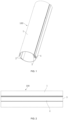
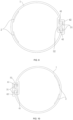
- FIG. 1 is a perspective view of a liquid-leakage detection device according to the embodiment of the present disclosure
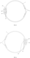
- FIG. 2 is a front view of the liquid-leakage detection device shown in FIG. 1
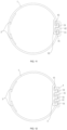
- FIG. 3 is a right view of the liquid-leakage detection device shown in FIG. 1
- FIG. 4 is a left view of the liquid-leakage detection device shown in FIG. 1 .
- the liquid-leakage detection device 100 includes a detection belt body 1, an electrode 2, a first connection member 3 and a second connection member 4.
- the detection belt body 1 is configured to wrap the outer surface of the to-be-detected device.
- the electrode 2 is connected to the detection belt body 1 and provided on one surface or inside of the detection belt body 1, so as to detect whether the to-be-detected device leaks liquid.
- the first connection member 3 is connected to a first side of the detection belt body 1, and the second connection member 4 is connected to a second side of the detection belt body 1 so as to connect with the first connection member 3.
- the first connection member 3 is connected to the second connection member 4 by buckling.
- first connection member 3, the second connection member 4, and the detection belt body 1 are integrally formed.
- first connection member 3, the second connection member 4, and the detection belt body 1 can be formed separately, and then assembled together, for example, they can be connected together by bonding or sewing.
- the detection belt body 1 When detecting whether a to-be-detected pipe leaks liquid, the detection belt body 1 is wrapped on an outer surface of the to-be-detected device, and the first connection member 3 is connected to the second connection member 4 by buckling, so that the detection belt body 1 can be fixedly wrapped on the outer surface of the to-be-detected device, and the electrode 2 can be tightly bonded to the outer surface of the to-be-detected device.
- the leaked liquid contacts with the electrode 2 to cause a change in the impedance of the electrode 2, so that whether the to-be-detected device leaks liquid can be determined based on the impedance change of the electrode 2, thereby achieving a high detection speed, and comprehensively detecting various leakage points of the pipe.
- the first connection member 3 includes multiple first buckling parts 31, and the second connection member 4 includes multiple second buckling parts 41.
- the shape and quantity of the second buckling part 41 correspond to the shape and quantity of the first buckling part 31, respectively, so that the second buckling parts 41 can buckle the first buckling parts 31, respectively, thereby realizing buckling connection between the first connection member 3 and the second connection member 4.
- the first buckling part 31 can be at least one of three structures consisting of a hook, a protrusion, and a groove
- the second buckling part can be at least one of three structures consisting of a hook, a protrusion, and a groove.
- the first buckling part 31 and the second buckling part 41 are both a hook structure.
- the first buckling part 31 and the second buckling part 41 can buckle together by means of buckling or pulling to form a stable hand-to-hand hooked structure.
- the stable structure has high strength and can still be fixed to each other even under hard pulling of different angles or directions, so that the detection belt body 1 can be stably wrapped on the outer surface of the to-be-detected device.
- the detection belt body is wrapped around the outer surface of the to-be-detected device to buckle the first buckling part with the second buckling part.
- the first buckling part and the second buckling part can be pulled apart, so that it is very easy to assemble and disassemble.
- the buckling of the first buckling part 31 and the second buckling part 41 can be performed in a manner of a chain joint tool or pressing. After buckling, excellent bonding strength can be realized, liquid can be prevented from flowing through the groove between the first buckling part and the second buckling part, so that they have waterproof function and maintain a pressure of 3 bar or more without leakage.
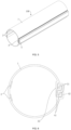
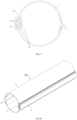
- first buckling part 31 and the second buckling part 41 are not limited to the structures shown in FIG. 3 and FIG. 4 , which can further be other structures, such as those shown in FIG. 5 to FIG.11 .
- the quantities of the first buckling part 31 and the second buckling part 41 can be 2 or more (as shown in FIG. 12 ), respectively, to meet different requirements of strength and leakage prevention.
- the quantities of first buckling part and second buckling part can be only one, respectively.
- first connection member 3 further includes a first connecting portion 32 connected to a first side of the detection belt body 1.
- the second connection member 4 further includes a second connecting portion 42 connected to a second side of the detection belt body 1.
- first buckling part 31 is arranged in parallel on the first connecting portion 32 along a width direction of the detection belt body 1
- the second buckling part 41 is arranged in parallel on the second connecting portion 42 along the width direction of the detection belt body 1.
- the first buckling part 31 and the second buckling part 41 are connected by buckling.
- the first buckling parts are spaced on the first connecting portion along the length direction of the detection belt body
- the second buckling parts are spaced on the second connecting portion along the length direction of the detection belt body
- the first buckling parts and the second buckling parts are connected by buckling, respectively.
- the detection belt body 1 has the characteristics of softness, transparency, and ultra-thinness.
- the detection belt body 1 can be quickly assembled and fixed by a zipper structure, making it convenient to use and highly reliable.
- the width of the detection belt body 1 is slightly larger than the circumference of the pipe at its outer diameter, its size has a greater flexibility. Different sizes can be selected for pipes having different outer diameters.
- the thickness of detection belt body 1 ranges from 0.1mm to 5mm, e.g., 0.1mm, 0.5mm, 1mm, 1.5mm, 2mm, 2.5mm, 3mm, 3.5mm, 4mm, 4.5mm, or 5mm, which can be other values within the above range, there is no limit here.
- the materials of the detection belt body 1 includes a flame retardant, so as to avoid the occurrence of fires due to spontaneous combustion.
- the materials of the detection belt body 1, the first connection member 3, and the second connection member 4 includes a thermoplastic material, respectively.
- the materials of the detection belt body 1 can include polyvinyl chloride (PVC), thermoplastic polyurethanes (TPU), polyethylene terephthalate (PET), polycarbonate (PC), fluorinated ethylene propylene (FEP), polytetrafluoroethylene (PTFE), Polyvinylidenefluoride (PVDF), or Polyfluoroalkoxy (PFA).
- the materials of the first connection member 3 and the second connection member 4 can include PVC, TPU, PET, PC, FEP, PTFE, PVDF, or PFA, respectively.
- the detection belt body 1 includes a water absorbing material layer and a color developing material layer. When liquid leakage occurs in pipe, the detection belt body 1 can adsorb the leaked liquid and display the leakage position for maintenance.
- Electrodes 2 are connected to one another and divided into positive electrodes and negative electrodes.
- multiple electrodes 2 are spaced on one surface or inside of the detection belt body 1 along a circumferential direction of the detection belt body 1 wrapping the to-be-detected device, so that there is no contact between two adjacent electrodes 2.
- the length direction of each electrode 2 extends along the length direction of the first connection member 3 and the second connection member 4, to be consistent with the length of the detection belt body.
- the electrode 2 can be fixed to the detection belt body 1 by means of hot pressing, bonding, or printing, in which the hot pressing process does not affect electrode 2.
- the materials of electrode 2 include a conductive ink, a metal alloy, a conductive cloth, a conductive foam, and a conductive foam.
- the cross-sectional shape of the electrode 2 is flat and extends along a predetermined geometric shape in the length direction of the detection belt body 1, e.g., it can be long strip shape, S-shape, or other shape according to different requirements.
- the thickness of the electrode 2 is 0.1mm to 2mm, e.g., 0.1mm, 0.3mm, 0.5mm, 0.7mm, 0.9mm, 1.1mm, 1.3mm, 1.5mm, 1.7mm, or 2mm.
- the width of electrode 2 is 0.1mm to 5mm, e.g., 0.1mm, 0.5mm, 1mm, 1.5mm, 2mm, 2.5mm, 3mm, 3.5mm, 4mm, 4.5mm, or 5mm, which can further be other values within the above range, and there is no limit here.
- the liquid-leakage detection device may further include multiple detection belt bodies.
- the detection belt body is provided with an electrode, a first connecting member, and a second connecting member. Two ends of the detection belt body are connected to other detection belt bodies through a connector or a lead wire.
- the liquid-leakage detection device of the present disclosure has a high detection speed and can comprehensively detect various leakage points in the pipe. Meanwhile, when the pipe leaks liquid, the liquid-leakage detection device can further prevent the liquid from leaking out and avoid damage to servers or other electrical facilities. In addition, the liquid-leakage detection device is easy to assemble and the disassembling operation can be performed independently of the pipe.
- any of the first buckling parts 31 can be a protrusion structure
- any of second buckling parts 41 can be a groove structure.
- the second buckling part 41 being the groove structure is arranged corresponding to the first buckling part 31 being the protrusion structure, so that the first buckling part 31 can be buckled with the second buckling part 41, realizing buckling connection between the first connection member 3 and the second connection member 4.
- any of the first buckling parts can be a groove structure
- any of the second buckling part can be a protrusion structure.
- the second buckling part being the protrusion structure is arranged corresponding to the first buckling part being the groove structure, so that the second buckling part can be buckled with the first buckling part 31, realizing buckling connection member between the first connection member and the second connection member.
- the present disclosure further provides another embodiment based on the above embodiment.
- This embodiment differs from the above embodiment that, as shown in FIG. 14 , in this embodiment, part of the first buckling parts 31 can be a hook structure, and part of the first buckling parts 31 can be a protrusion structure.
- Part of the second buckling parts 41 can be a hook like structure, and part of the second buckling parts 41 can be a groove structure.
- the second buckling part 41 being the hook structure is arranged corresponding to the first buckling part 31 being the hook structure, and the second buckling part 41 being the groove structure is arranged corresponding to the first buckling part 31 being the protrusion structure, so that the second buckling part 41 can buckle with the first buckling part 31, realizing buckling connection between the first connection member 3 and the second connection member 4.
- part of the first buckling parts can be a hook structure, and part of the first buckling parts can be a groove structure.
- Part of the second buckling parts can be a hook structure, and part of the second buckling parts can be a protrusion structure.
- the second buckling part being the hook structure is arranged corresponding to the first buckling part being the hook structure, and the second buckling part being the protrusion structure is arranged corresponding to the first buckling part being the groove structure, so that the second buckling part can buckle with the first buckling part, realizing buckling connection between the first connection member and the second connection member.
- the present disclosure realizes the buckling connection between the first connection member 3 and the second connection member 4 by means of buckling the first buckling part with the second buckling part, and has the advantages of compact structure, high strength, and ease use.
- the liquid-leakage detection device of the present disclosure has following advantages: the liquid-leakage detection device can quickly detect liquid-leakage even with small amounts of liquid, and predict the leakage situation.
- the liquid-leakage detection device can comprehensively detect liquid-leakage, taking into account each internal liquid-leakage risk point and liquid-leakage direction.
- the liquid-leakage detection device is easy to assemble and maintain, so as to quickly maintain and put into use again.
- the liquid-leakage detection device has high reliability, low false alarm probability and long service life.
- the liquid-leakage detection device has a certain plugging ability which can give the maintenance personnel response time and processing time to avoid loss expansion.
- the liquid-leakage detection device can be quickly maintained to quickly find problems by displaying leakage points on site, and the liquid-leakage detection device can quickly remove the leaked liquid, shortening the maintenance time.
Landscapes
- Physics & Mathematics (AREA)
- General Physics & Mathematics (AREA)
- Engineering & Computer Science (AREA)
- Computer Hardware Design (AREA)
- General Engineering & Computer Science (AREA)
- Microelectronics & Electronic Packaging (AREA)
- Examining Or Testing Airtightness (AREA)
Abstract
Description
- The present application claims priority to
Chinese Patent Application No. 202221674461.3, filed on June 29, 2022 - The present disclosure relates to the technical field of liquid-leakage detection, and in particular, to a liquid-leakage detection device.
- A pipe is an essential component in a process of liquid transportation. However, due to aging of the pipe, change of climate environment, and artificial damage, pipe leakage accidents occur from time to time. Moreover, pipes are mostly located inside a device, and operating environment thereof is relatively complex.
- In the related art, in order to accurately detect the location of liquid-leakage of the pipe, liquid-leakage is detected by using an annular liquid-leakage detection sensor. The annular liquid-leakage detection sensor is wrapped by clamps and locking members on a periphery surface of the pipe that needs to detect liquid-leakage. The fixing manners of the related art at least has following problems: a worker need to assemble the clamps and locking members one by one when the liquid-leakage detection sensor is assembled, and a maintenance person need to disassemble all the locking parts before removing the liquid-leakage detection sensor in maintenance, causing low assembling and disassembling efficiency.
- In order to overcome the above problems in the related art, a main objective of the present disclosure is to provide a liquid-leakage detection device that can improve the assembling and disassembling efficiency.
- In one aspect, the present disclosure provides a liquid-leakage detection device. The liquid-leakage detection device includes a detection belt body, an electrode, a first connection member and a second connection member. The detection belt body is configured to wrap an outer surface of a to-be-detected device. The electrode is configured to detect whether the to-be-detected device leaks liquid. The electrode is connected to the detection belt body and disposed on one surface or inside of the detection belt body. The first connection member connected to a first side of the detection belt body and includes at least one first buckling part. The second connection member is connected to a second side of the detection belt body and includes at least one second buckling part. The second buckling part is capable of buckling with the first buckling part so that the first connection member is connected to the second connection member by buckling.
- In some embodiments, the first buckling part is at least one of three structures consisting of a hook, a protrusion, and a groove; and the second buckling part is at least one of three structures consisting of a hook, a protrusion, and a groove, and a shape and quantity of the second buckling part are set corresponding to a shape and quantity of the first buckling part.
- In some embodiments, each of the first buckling part and the second buckling part is a hook structure; or the first buckling part is a protrusion structure, and the second buckling part is a groove structure; or the first buckling part is a groove structure, and the second buckling part is a protrusion structure.
- In some embodiments, the first connection member further includes a first connecting portion connected to a first side of the detection belt body, the second connection member further includes a second connecting portion connected to a second side of the detection belt body, at least two second buckling parts are provided, and at least two first buckling parts are provided; the at least two first buckling parts are arranged on the first connecting portion along a length direction of the detection belt body, the at least two second buckling parts are arranged on the second connecting portion along the length direction of the detection belt body, and the first buckling part and the second buckling part are connected by buckling; or the at least two first buckling parts are arranged in parallel on the first connecting portion along a width direction of the detection belt body, the at least two second buckling parts are arranged in parallel on the second connecting portion along the width direction of the detection belt body, and the first buckling part and the second buckling part are connected by buckling.
- In some embodiments, the first connection member and the second connection member are integrally formed with the detection belt body.
- In some embodiments, the detection belt body has a thickness of 0.1mm-5mm; or the electrode has a thickness of 0.1 mm-2mm, and a width of 0.1 mm-5mm.
- In some embodiments, the detection belt body includes a water absorbing material layer and/or a color developing material layer.
- In some embodiments, at least two electrodes are provided, the at least two electrodes are spaced on one surface or inside of the detection belt body along a circumferential direction of the detection belt body upon wrapping the to-be-detected device, and a length of the at least two electrodes extends along length directions of the first connection member and the second connection member.
- In some embodiments, the at least two electrodes extend along a predetermined geometric shape in a length direction of the detection belt body.
- In some embodiments, the detection belt body is made of a thermoplastic material, and/or each of the first connection member and the second connection member is made of a thermoplastic material.
- Compared to the prior are, the liquid-leakage detection device includes a detection belt body, an electrode, a first connection member and a second connection member. The detection belt body is configured to wrap an outer surface of a to-be-detected device. The electrode is configured to detect whether the to-be-detected device leaks liquid. The electrode is connected to the detection belt body and disposed on one surface or inside of the detection belt body. The first connection member connected to a first side of the detection belt body and includes at least one first buckling part. The second connection member is connected to a second side of the detection belt body and includes at least one second buckling part. The second buckling part is capable of buckling with the first buckling part so that the first connection member is connected to the second connection member by buckling. The detection belt body is wrapped around the outer surface of the to-be-detected device when the liquid-leakage detection device is assembled, making the first buckling part and the second buckling part buckle with each other, and the first buckling part and the second buckling part can be unzipped when the liquid-leakage detection device is dissembled, so as to effectively improving the assembling and disassembling efficiency.
-
- Fig. 1
- is a perspective view of a liquid-leakage detection device according to an embodiment of the present disclosure.
- Fig. 2
- is a front view of the liquid-leakage detection device shown in
FIG. 1 . - Fig. 3
- is a right view of the liquid-leakage detection device shown in
FIG. 1 . - Fig. 4
- is a left view of the liquid-leakage detection device shown in
FIG. 1 . - Fig. 5
- is a perspective view of a liquid-leakage detection device according to another embodiment of the present disclosure.
- Fig. 6
- is a left view of the liquid-leakage detection device shown in
FIG. 5 . - Fig. 7
- is a right view of the liquid-leakage detection device shown in
FIG. 5 . - Fig. 8
- is a perspective view of a liquid-leakage detection device according to another embodiment of the present disclosure.
- Fig. 9
- is a left view of the liquid-leakage detection device shown in
FIG. 8 . - Fig. 10
- is a right view of the liquid-leakage detection device shown in
FIG. 8 . - Figs. 11-14
- are a side view of a liquid-leakage detection device according to some embodiments of the present disclosure, respecitively.
- 1: detection belt body; 2: electrode; 3: first connection member; 31: first buckling part; 32: first connecting portion; 4: second connection member; 41: second buckling part; 42: second connecting portion; 100: liquid-leakage detection device.
- In order to more clearly illustrate objectives, technical solutions, and advantages of the embodiments of the present disclosure, the technical solutions in the embodiments of the present disclosure are clearly and completely described in details with reference to the accompanying drawings. It should be understood that the embodiments described here are intended to explain the present disclosure and not to limit it.
- The terms "first" and "second" in the present disclosure are only used for a purpose of description and cannot be understood as indicating or implying relative importance, unless noted otherwise. Unless noted otherwise, the term "multiple" refers to two or more. The terms "connection" and "fixation" should be understood in a broad sense. For example, "connection" can be a fixed connection, a removable connection, an integrated connection, or an electrical connection. And "connection" can be directly connected or indirectly connected through an intermediate. For those skilled in the art, the meanings of the above terms in the present disclosure can be understood based on particular circumstances.
- It should be understood that the directional terms "above" and "below" described in the present disclosure are described from the view angle of the drawings and should not be understood as limiting the embodiments of the present disclosure. In addition, in the context, it should be understood that when one element is connected "above" or "below" another element, the one element can not only be directly connected "above" or "below" another element, but also indirectly connected "above" or "below" another element through an intermediate.
- Limited to the requirements of detection environment and reliability, most liquid-leakage detection solutions in the related art use passive detection. A sensor detects a signal change to prompt the liquid-leakage alarm only if the liquid comes into contact with the sensor. It is more suitable for large industrial occasions such as traditional factories, oil depots, and long-distance pipes. When the leaked liquid is found, even if it has been leaking for a certain period of time, the losses are within a controllable range, leading to lower detection requirements and higher requirements for sensor durability and reliability, and requiring adaptation to different harsh operating conditions. Moreover, due to the detection liquids in the past were generally liquids with high conductivity such as acid or base liquids, once a liquid-leakage occurs, the amount of leaked liquid is large. The detection requirements and difficulty are not high. And the electromagnetic environment is relatively simple, and the sensor is less disturbed.
- At present, the liquid-leakage detection solution for pipes with complex operating conditions (for example, pipes with small outer diameters and complex structures) is still in an immature state. The materials and structures of pipes are complex and diverse, and the types of flowing liquids are also diverse, bringing great difficulty and challenges to detection performance and reliability of liquid-leakage detection.
- The liquid-leakage detection manners in the related art include: 1) after collecting the leaked liquid by a water collecting tray or a water receiving tray, the impedance of a point sensor after contact with the leaked liquid or the electrical/optical signal changes generated by light refraction are used to sense the leaked liquid; 2) the leaked liquid is detected by using a liquid-leakage detection rope or a liquid-leakage detection belt, mainly used for large plane spaces, such as ground, bottom of equipment, and underground pipelines. Its detection principle is to use leaked liquid to contact with a water immersion rope, causing changes in the impedance or capacitance of the sensing cable; 3) liquid-leakage detection is performed by using optical signals, and a liquid-leakage detection fiber contacts the surface of the fiber through light, causing the optical signal to refract at the leakage point, thereby realizing the liquid-leakage detection by detecting the signal changes at the receiving end; and 4) liquid-leakage detection is performed by RFID technology. Its detection principle is that by using the characteristic that the capacitance of the detected liquid is significantly greater than the air, the transmission of ultra-high frequency signals can be affected by the liquid contacted, realizing liquid-leakage detection.
- For the first detection method mentioned above, the detection is centralized, so as to avoid false alarm interference. However, a large amount of leakage generally has occurred when leaked liquid is sensed, causing significant losses, and the first detection method is not suitable for the current demand for liquid-leakage detection. For the second detection method mentioned above, the leakage is detected by the impedance or capacitive reactance changes after the liquid comes into contact with the sensing rope, and the characteristic is that the sensing rope is wrapped around the pipe. However, the second detection method cannot detect all positions due to the small diameter and soft material required by the sensing rope, and the assembling and fixation are complex, affecting the detection effect. For the third detection method mentioned above, the cost of detectors and sensors is significantly higher than other detection methods, and fiber optic liquid-leakage detection has high requirements for pipe assembling. And for the fourth detection method mentioned above, wireless detection can be achieved, but the existing technology still faces problems such as high power consumption, high cost, high interference, and poor detection efficiency.
- As mentioned above, the existing liquid-leakage detection method has the following defects: the response of liquid-leakage detection is slow and the probability of false alarms is high, affecting the accuracy of liquid-leakage detection. The liquid-leakage detection sensor can only cover relatively simple parts of the structure and cannot cover all leakage points. The space of the secondary liquid cooled side structure is narrow, making it difficult to assemble and disassemble, and affecting efficiency and sensor accuracy. At present, liquid-leakage detection can only realize leakage alarm, but cannot deal with leaked liquid immediately. And leakage points are difficult to detect, and maintenance and analysis take a long time.
- Referring to
FIG. 1 to FIG. 4 ,FIG. 1 is a perspective view of a liquid-leakage detection device according to the embodiment of the present disclosure,FIG. 2 is a front view of the liquid-leakage detection device shown inFIG. 1 ,FIG. 3 is a right view of the liquid-leakage detection device shown inFIG. 1 , andFIG. 4 is a left view of the liquid-leakage detection device shown inFIG. 1 . The liquid-leakage detection device 100 includes adetection belt body 1, anelectrode 2, afirst connection member 3 and asecond connection member 4. Thedetection belt body 1 is configured to wrap the outer surface of the to-be-detected device. Theelectrode 2 is connected to thedetection belt body 1 and provided on one surface or inside of thedetection belt body 1, so as to detect whether the to-be-detected device leaks liquid. Thefirst connection member 3 is connected to a first side of thedetection belt body 1, and thesecond connection member 4 is connected to a second side of thedetection belt body 1 so as to connect with thefirst connection member 3. Thefirst connection member 3 is connected to thesecond connection member 4 by buckling. - In this embodiment, the
first connection member 3, thesecond connection member 4, and thedetection belt body 1 are integrally formed. In some embodiments, thefirst connection member 3, thesecond connection member 4, and thedetection belt body 1 can be formed separately, and then assembled together, for example, they can be connected together by bonding or sewing. - When detecting whether a to-be-detected pipe leaks liquid, the
detection belt body 1 is wrapped on an outer surface of the to-be-detected device, and thefirst connection member 3 is connected to thesecond connection member 4 by buckling, so that thedetection belt body 1 can be fixedly wrapped on the outer surface of the to-be-detected device, and theelectrode 2 can be tightly bonded to the outer surface of the to-be-detected device. When the to-be-detected device leaks liquid, the leaked liquid contacts with theelectrode 2 to cause a change in the impedance of theelectrode 2, so that whether the to-be-detected device leaks liquid can be determined based on the impedance change of theelectrode 2, thereby achieving a high detection speed, and comprehensively detecting various leakage points of the pipe. - In this embodiment, the
first connection member 3 includes multiple first bucklingparts 31, and thesecond connection member 4 includes multiple second bucklingparts 41. The shape and quantity of the second bucklingpart 41 correspond to the shape and quantity of the first bucklingpart 31, respectively, so that the second bucklingparts 41 can buckle the first bucklingparts 31, respectively, thereby realizing buckling connection between thefirst connection member 3 and thesecond connection member 4. The first bucklingpart 31 can be at least one of three structures consisting of a hook, a protrusion, and a groove, and the second buckling part can be at least one of three structures consisting of a hook, a protrusion, and a groove. In this embodiment, the first bucklingpart 31 and the second bucklingpart 41 are both a hook structure. - In this embodiment, the first buckling
part 31 and the second bucklingpart 41 can buckle together by means of buckling or pulling to form a stable hand-to-hand hooked structure. The stable structure has high strength and can still be fixed to each other even under hard pulling of different angles or directions, so that thedetection belt body 1 can be stably wrapped on the outer surface of the to-be-detected device. Meanwhile, when the liquid-leakage detection device is assembled, the detection belt body is wrapped around the outer surface of the to-be-detected device to buckle the first buckling part with the second buckling part. When the liquid-leakage detection device is disassembled, the first buckling part and the second buckling part can be pulled apart, so that it is very easy to assemble and disassemble. - When the buckling of the first buckling
part 31 and the second bucklingpart 41 is realized, the buckling can be performed in a manner of a chain joint tool or pressing. After buckling, excellent bonding strength can be realized, liquid can be prevented from flowing through the groove between the first buckling part and the second buckling part, so that they have waterproof function and maintain a pressure of 3 bar or more without leakage. - Further, the structures of the first buckling
part 31 and the second bucklingpart 41 are not limited to the structures shown inFIG. 3 and FIG. 4 , which can further be other structures, such as those shown inFIG. 5 to FIG.11 . Moreover, the quantities of the first bucklingpart 31 and the second bucklingpart 41 can be 2 or more (as shown inFIG. 12 ), respectively, to meet different requirements of strength and leakage prevention. The quantities of first buckling part and second buckling part can be only one, respectively. - Further, the
first connection member 3 further includes a first connectingportion 32 connected to a first side of thedetection belt body 1. Thesecond connection member 4 further includes a second connectingportion 42 connected to a second side of thedetection belt body 1. In this embodiment, the first bucklingpart 31 is arranged in parallel on the first connectingportion 32 along a width direction of thedetection belt body 1, and the second bucklingpart 41 is arranged in parallel on the second connectingportion 42 along the width direction of thedetection belt body 1. The first bucklingpart 31 and the second bucklingpart 41 are connected by buckling. In other embodiments, it can be understood that the first buckling parts are spaced on the first connecting portion along the length direction of the detection belt body, and the second buckling parts are spaced on the second connecting portion along the length direction of the detection belt body, and the first buckling parts and the second buckling parts are connected by buckling, respectively. In order to improve the wrapping effect of thedetection belt body 1 on the to-be-detected device, thedetection belt body 1 has the characteristics of softness, transparency, and ultra-thinness. Thedetection belt body 1 can be quickly assembled and fixed by a zipper structure, making it convenient to use and highly reliable. - Further, the width of the
detection belt body 1 is slightly larger than the circumference of the pipe at its outer diameter, its size has a greater flexibility. Different sizes can be selected for pipes having different outer diameters. The thickness ofdetection belt body 1 ranges from 0.1mm to 5mm, e.g., 0.1mm, 0.5mm, 1mm, 1.5mm, 2mm, 2.5mm, 3mm, 3.5mm, 4mm, 4.5mm, or 5mm, which can be other values within the above range, there is no limit here. - The materials of the
detection belt body 1 includes a flame retardant, so as to avoid the occurrence of fires due to spontaneous combustion. In an embodiment, the materials of thedetection belt body 1, thefirst connection member 3, and thesecond connection member 4 includes a thermoplastic material, respectively. For example, the materials of thedetection belt body 1 can include polyvinyl chloride (PVC), thermoplastic polyurethanes (TPU), polyethylene terephthalate (PET), polycarbonate (PC), fluorinated ethylene propylene (FEP), polytetrafluoroethylene (PTFE), Polyvinylidenefluoride (PVDF), or Polyfluoroalkoxy (PFA). The materials of thefirst connection member 3 and thesecond connection member 4 can include PVC, TPU, PET, PC, FEP, PTFE, PVDF, or PFA, respectively. - To facilitate maintenance, the
detection belt body 1 includes a water absorbing material layer and a color developing material layer. When liquid leakage occurs in pipe, thedetection belt body 1 can adsorb the leaked liquid and display the leakage position for maintenance. -
Multiple electrodes 2 are connected to one another and divided into positive electrodes and negative electrodes. In an embodiment,multiple electrodes 2 are spaced on one surface or inside of thedetection belt body 1 along a circumferential direction of thedetection belt body 1 wrapping the to-be-detected device, so that there is no contact between twoadjacent electrodes 2. The length direction of eachelectrode 2 extends along the length direction of thefirst connection member 3 and thesecond connection member 4, to be consistent with the length of the detection belt body. Theelectrode 2 can be fixed to thedetection belt body 1 by means of hot pressing, bonding, or printing, in which the hot pressing process does not affectelectrode 2. - In this embodiment, due to the tensile resistance and bending resistance of the
electrode 2, whether the pipe leaks liquid is detected through theelectrode 2, so that the liquid-leakage detection device has high reliability. - Further, the materials of
electrode 2 include a conductive ink, a metal alloy, a conductive cloth, a conductive foam, and a conductive foam. The cross-sectional shape of theelectrode 2 is flat and extends along a predetermined geometric shape in the length direction of thedetection belt body 1, e.g., it can be long strip shape, S-shape, or other shape according to different requirements. The thickness of theelectrode 2 is 0.1mm to 2mm, e.g., 0.1mm, 0.3mm, 0.5mm, 0.7mm, 0.9mm, 1.1mm, 1.3mm, 1.5mm, 1.7mm, or 2mm. The width ofelectrode 2 is 0.1mm to 5mm, e.g., 0.1mm, 0.5mm, 1mm, 1.5mm, 2mm, 2.5mm, 3mm, 3.5mm, 4mm, 4.5mm, or 5mm, which can further be other values within the above range, and there is no limit here. - In some embodiments, the liquid-leakage detection device may further include multiple detection belt bodies. The detection belt body is provided with an electrode, a first connecting member, and a second connecting member. Two ends of the detection belt body are connected to other detection belt bodies through a connector or a lead wire.
- The liquid-leakage detection device of the present disclosure has a high detection speed and can comprehensively detect various leakage points in the pipe. Meanwhile, when the pipe leaks liquid, the liquid-leakage detection device can further prevent the liquid from leaking out and avoid damage to servers or other electrical facilities. In addition, the liquid-leakage detection device is easy to assemble and the disassembling operation can be performed independently of the pipe.
- The present disclosure further provides another embodiment based on the above embodiment. This embodiment differs from the above embodiment that, as shown in
FIG. 13 , in this embodiment, any of the first bucklingparts 31 can be a protrusion structure, and any of second bucklingparts 41 can be a groove structure. The second bucklingpart 41 being the groove structure is arranged corresponding to the first bucklingpart 31 being the protrusion structure, so that the first bucklingpart 31 can be buckled with the second bucklingpart 41, realizing buckling connection between thefirst connection member 3 and thesecond connection member 4. - In other embodiments, it can be understood that any of the first buckling parts can be a groove structure, and any of the second buckling part can be a protrusion structure. The second buckling part being the protrusion structure is arranged corresponding to the first buckling part being the groove structure, so that the second buckling part can be buckled with the first buckling
part 31, realizing buckling connection member between the first connection member and the second connection member. - The present disclosure further provides another embodiment based on the above embodiment. This embodiment differs from the above embodiment that, as shown in
FIG. 14 , in this embodiment, part of the first bucklingparts 31 can be a hook structure, and part of the first bucklingparts 31 can be a protrusion structure. Part of the second bucklingparts 41 can be a hook like structure, and part of the second bucklingparts 41 can be a groove structure. The second bucklingpart 41 being the hook structure is arranged corresponding to the first bucklingpart 31 being the hook structure, and the second bucklingpart 41 being the groove structure is arranged corresponding to the first bucklingpart 31 being the protrusion structure, so that the second bucklingpart 41 can buckle with the first bucklingpart 31, realizing buckling connection between thefirst connection member 3 and thesecond connection member 4. - In some embodiments, it can be understood that part of the first buckling parts can be a hook structure, and part of the first buckling parts can be a groove structure. Part of the second buckling parts can be a hook structure, and part of the second buckling parts can be a protrusion structure. The second buckling part being the hook structure is arranged corresponding to the first buckling part being the hook structure, and the second buckling part being the protrusion structure is arranged corresponding to the first buckling part being the groove structure, so that the second buckling part can buckle with the first buckling part, realizing buckling connection between the first connection member and the second connection member.
- The present disclosure realizes the buckling connection between the
first connection member 3 and thesecond connection member 4 by means of buckling the first buckling part with the second buckling part, and has the advantages of compact structure, high strength, and ease use. - The liquid-leakage detection device of the present disclosure has following advantages: the liquid-leakage detection device can quickly detect liquid-leakage even with small amounts of liquid, and predict the leakage situation. The liquid-leakage detection device can comprehensively detect liquid-leakage, taking into account each internal liquid-leakage risk point and liquid-leakage direction. The liquid-leakage detection device is easy to assemble and maintain, so as to quickly maintain and put into use again. The liquid-leakage detection device has high reliability, low false alarm probability and long service life. The liquid-leakage detection device has a certain plugging ability which can give the maintenance personnel response time and processing time to avoid loss expansion. The liquid-leakage detection device can be quickly maintained to quickly find problems by displaying leakage points on site, and the liquid-leakage detection device can quickly remove the leaked liquid, shortening the maintenance time.
- The above is merely preferred embodiments of the present disclosure, but the protection scope of the present disclosure is not limited to these embodiments. Any changes or substitutions easily conceived by a person skilled in the art within the protection scope of the present disclosure should fall within the protection scope of the present disclosure. Therefore, the protection scope of the present disclosure should be based on the protection scope of the claims.
Claims (14)
the electrode has a thickness of 0.1mm-2mm, and a width of 0.1mm-5mm.
Applications Claiming Priority (1)
| Application Number | Priority Date | Filing Date | Title |
|---|---|---|---|
| CN202221674461.3U CN217603891U (en) | 2022-06-29 | 2022-06-29 | Liquid leakage detection device |
Publications (2)
| Publication Number | Publication Date |
|---|---|
| EP4300065A1 true EP4300065A1 (en) | 2024-01-03 |
| EP4300065B1 EP4300065B1 (en) | 2026-01-28 |
Family
ID=83592941
Family Applications (1)
| Application Number | Title | Priority Date | Filing Date |
|---|---|---|---|
| EP23182107.5A Active EP4300065B1 (en) | 2022-06-29 | 2023-06-28 | Liquid-leakage detection device |
Country Status (3)
| Country | Link |
|---|---|
| US (1) | US20240003773A1 (en) |
| EP (1) | EP4300065B1 (en) |
| CN (1) | CN217603891U (en) |
Families Citing this family (1)
| Publication number | Priority date | Publication date | Assignee | Title |
|---|---|---|---|---|
| CN117419863A (en) * | 2023-10-13 | 2024-01-19 | 深圳市英维克科技股份有限公司 | Leak detection device |
Citations (4)
| Publication number | Priority date | Publication date | Assignee | Title |
|---|---|---|---|---|
| DE1704888A1 (en) * | 1967-07-25 | 1971-11-18 | Opti Holding Ag | Process for the production of rows of fastener links for zippers made of thermoplastic material and a zipper made afterwards |
| EP2757359B1 (en) * | 2012-12-12 | 2017-04-19 | Piller Entgrattechnik GmbH | Apparatus for detecting leaks from a fluid conduit, in particular a high pressure liquid conduit |
| DE202018101539U1 (en) * | 2018-03-20 | 2018-04-30 | Marvin Oppermann | Device for locating a leak at a fluid-carrying section |
| US20190162625A1 (en) * | 2017-11-27 | 2019-05-30 | Saint-Gobain Performance Plastics Corporation | Leak detection system and method of making and using the same |
-
2022
- 2022-06-29 CN CN202221674461.3U patent/CN217603891U/en active Active
-
2023
- 2023-06-28 EP EP23182107.5A patent/EP4300065B1/en active Active
- 2023-06-29 US US18/344,026 patent/US20240003773A1/en active Pending
Patent Citations (4)
| Publication number | Priority date | Publication date | Assignee | Title |
|---|---|---|---|---|
| DE1704888A1 (en) * | 1967-07-25 | 1971-11-18 | Opti Holding Ag | Process for the production of rows of fastener links for zippers made of thermoplastic material and a zipper made afterwards |
| EP2757359B1 (en) * | 2012-12-12 | 2017-04-19 | Piller Entgrattechnik GmbH | Apparatus for detecting leaks from a fluid conduit, in particular a high pressure liquid conduit |
| US20190162625A1 (en) * | 2017-11-27 | 2019-05-30 | Saint-Gobain Performance Plastics Corporation | Leak detection system and method of making and using the same |
| DE202018101539U1 (en) * | 2018-03-20 | 2018-04-30 | Marvin Oppermann | Device for locating a leak at a fluid-carrying section |
Also Published As
| Publication number | Publication date |
|---|---|
| EP4300065B1 (en) | 2026-01-28 |
| CN217603891U (en) | 2022-10-18 |
| US20240003773A1 (en) | 2024-01-04 |
Similar Documents
| Publication | Publication Date | Title |
|---|---|---|
| US9556977B2 (en) | Apparatus for flexible pipe body and method of producing same | |
| US7555936B2 (en) | Hydraulic hose with integral life-sensing capability and method therefor | |
| US4270049A (en) | Liquid leakage detection system | |
| US8064738B2 (en) | Leak detector using an optical fibre | |
| ES2720161T3 (en) | Sensor sleeve to monitor the health of an item | |
| US4570477A (en) | Leak detecting cable | |
| CN102692285B (en) | Temperature measuring equipment | |
| EP3412951B1 (en) | Marine hose status monitoring system | |
| US7316154B1 (en) | Seals with integrated leak progression detection capability | |
| EP4300065B1 (en) | Liquid-leakage detection device | |
| EP3412952B1 (en) | Marine hose status monitoring system | |
| CN103282757A (en) | Leak detection system | |
| US20180024024A1 (en) | System for monitoring pipeline leakage, pipeline element provided with the system, and method for mounting the monitoring system onto a pipeline | |
| US20250164340A1 (en) | Liquid Leakage Detection Device | |
| US20090314097A1 (en) | Method of measuring strain in a flex hose or other flexible member | |
| CN120100973B (en) | Intelligent leakage warning flexible composite pipeline system and warning method | |
| CN218496345U (en) | Liquid leakage detection sensor | |
| EP1460408A1 (en) | Leak detection system and method for offshore hose lines | |
| WO2011046463A1 (en) | Fluid pipe and method for detecting a deformation on the fluid pipe | |
| CN104565670B (en) | The detection method and detecting system leaked in flexible joint, connector | |
| KR101861237B1 (en) | Leak detection cable for liquids | |
| CN113917640A (en) | Double-sheath sensing optical cable | |
| KR20190133518A (en) | Leak detecting apparatus | |
| US10162145B2 (en) | Optical fibre installation in flexible riser | |
| US20240077007A1 (en) | System and method for detecting a failure in a fluid path of a fluid system |
Legal Events
| Date | Code | Title | Description |
|---|---|---|---|
| PUAI | Public reference made under article 153(3) epc to a published international application that has entered the european phase |
Free format text: ORIGINAL CODE: 0009012 |
|
| STAA | Information on the status of an ep patent application or granted ep patent |
Free format text: STATUS: THE APPLICATION HAS BEEN PUBLISHED |
|
| STAA | Information on the status of an ep patent application or granted ep patent |
Free format text: STATUS: REQUEST FOR EXAMINATION WAS MADE |
|
| AK | Designated contracting states |
Kind code of ref document: A1 Designated state(s): AL AT BE BG CH CY CZ DE DK EE ES FI FR GB GR HR HU IE IS IT LI LT LU LV MC ME MK MT NL NO PL PT RO RS SE SI SK SM TR |
|
| 17P | Request for examination filed |
Effective date: 20231215 |
|
| RBV | Designated contracting states (corrected) |
Designated state(s): AL AT BE BG CH CY CZ DE DK EE ES FI FR GB GR HR HU IE IS IT LI LT LU LV MC ME MK MT NL NO PL PT RO RS SE SI SK SM TR |
|
| GRAP | Despatch of communication of intention to grant a patent |
Free format text: ORIGINAL CODE: EPIDOSNIGR1 |
|
| STAA | Information on the status of an ep patent application or granted ep patent |
Free format text: STATUS: GRANT OF PATENT IS INTENDED |
|
| INTG | Intention to grant announced |
Effective date: 20250821 |
|
| GRAS | Grant fee paid |
Free format text: ORIGINAL CODE: EPIDOSNIGR3 |
|
| GRAA | (expected) grant |
Free format text: ORIGINAL CODE: 0009210 |
|
| STAA | Information on the status of an ep patent application or granted ep patent |
Free format text: STATUS: THE PATENT HAS BEEN GRANTED |
|
| AK | Designated contracting states |
Kind code of ref document: B1 Designated state(s): AL AT BE BG CH CY CZ DE DK EE ES FI FR GB GR HR HU IE IS IT LI LT LU LV MC ME MK MT NL NO PL PT RO RS SE SI SK SM TR |
|
| REG | Reference to a national code |
Ref country code: CH Ref legal event code: F10 Free format text: ST27 STATUS EVENT CODE: U-0-0-F10-F00 (AS PROVIDED BY THE NATIONAL OFFICE) Effective date: 20260128 Ref country code: GB Ref legal event code: FG4D |
|
| REG | Reference to a national code |
Ref country code: DE Ref legal event code: R096 Ref document number: 602023011191 Country of ref document: DE |
|
| P01 | Opt-out of the competence of the unified patent court (upc) registered |
Free format text: CASE NUMBER: UPC_APP_0001673_4300065/2026 Effective date: 20260119 |
|
| REG | Reference to a national code |
Ref country code: IE Ref legal event code: FG4D |
|
| REG | Reference to a national code |
Ref country code: NL Ref legal event code: MP Effective date: 20260128 |
|
| PG25 | Lapsed in a contracting state [announced via postgrant information from national office to epo] |
Ref country code: NL Free format text: LAPSE BECAUSE OF FAILURE TO SUBMIT A TRANSLATION OF THE DESCRIPTION OR TO PAY THE FEE WITHIN THE PRESCRIBED TIME-LIMIT Effective date: 20260128 |
|
| REG | Reference to a national code |
Ref country code: AT Ref legal event code: MK05 Ref document number: 1881828 Country of ref document: AT Kind code of ref document: T Effective date: 20260128 |
|
| PG25 | Lapsed in a contracting state [announced via postgrant information from national office to epo] |
Ref country code: RS Free format text: LAPSE BECAUSE OF FAILURE TO SUBMIT A TRANSLATION OF THE DESCRIPTION OR TO PAY THE FEE WITHIN THE PRESCRIBED TIME-LIMIT Effective date: 20260428 |
|
| PG25 | Lapsed in a contracting state [announced via postgrant information from national office to epo] |
Ref country code: ES Free format text: LAPSE BECAUSE OF FAILURE TO SUBMIT A TRANSLATION OF THE DESCRIPTION OR TO PAY THE FEE WITHIN THE PRESCRIBED TIME-LIMIT Effective date: 20260128 |
|
| PG25 | Lapsed in a contracting state [announced via postgrant information from national office to epo] |
Ref country code: PL Free format text: LAPSE BECAUSE OF FAILURE TO SUBMIT A TRANSLATION OF THE DESCRIPTION OR TO PAY THE FEE WITHIN THE PRESCRIBED TIME-LIMIT Effective date: 20260128 |
|
| PG25 | Lapsed in a contracting state [announced via postgrant information from national office to epo] |
Ref country code: GR Free format text: LAPSE BECAUSE OF FAILURE TO SUBMIT A TRANSLATION OF THE DESCRIPTION OR TO PAY THE FEE WITHIN THE PRESCRIBED TIME-LIMIT Effective date: 20260429 |
|
| REG | Reference to a national code |
Ref country code: LT Ref legal event code: MG9D |
|
| PG25 | Lapsed in a contracting state [announced via postgrant information from national office to epo] |
Ref country code: LT Free format text: LAPSE BECAUSE OF FAILURE TO SUBMIT A TRANSLATION OF THE DESCRIPTION OR TO PAY THE FEE WITHIN THE PRESCRIBED TIME-LIMIT Effective date: 20260128 |
|
| PGFP | Annual fee paid to national office [announced via postgrant information from national office to epo] |
Ref country code: DE Payment date: 20260612 Year of fee payment: 4 |
|
| PG25 | Lapsed in a contracting state [announced via postgrant information from national office to epo] |
Ref country code: NO Free format text: LAPSE BECAUSE OF FAILURE TO SUBMIT A TRANSLATION OF THE DESCRIPTION OR TO PAY THE FEE WITHIN THE PRESCRIBED TIME-LIMIT Effective date: 20260428 |
|
| PG25 | Lapsed in a contracting state [announced via postgrant information from national office to epo] |
Ref country code: SE Free format text: LAPSE BECAUSE OF FAILURE TO SUBMIT A TRANSLATION OF THE DESCRIPTION OR TO PAY THE FEE WITHIN THE PRESCRIBED TIME-LIMIT Effective date: 20260128 Ref country code: AT Free format text: LAPSE BECAUSE OF FAILURE TO SUBMIT A TRANSLATION OF THE DESCRIPTION OR TO PAY THE FEE WITHIN THE PRESCRIBED TIME-LIMIT Effective date: 20260128 Ref country code: FI Free format text: LAPSE BECAUSE OF FAILURE TO SUBMIT A TRANSLATION OF THE DESCRIPTION OR TO PAY THE FEE WITHIN THE PRESCRIBED TIME-LIMIT Effective date: 20260128 |
|
| PG25 | Lapsed in a contracting state [announced via postgrant information from national office to epo] |
Ref country code: HR Free format text: LAPSE BECAUSE OF FAILURE TO SUBMIT A TRANSLATION OF THE DESCRIPTION OR TO PAY THE FEE WITHIN THE PRESCRIBED TIME-LIMIT Effective date: 20260128 |
|
| PG25 | Lapsed in a contracting state [announced via postgrant information from national office to epo] |
Ref country code: IS Free format text: LAPSE BECAUSE OF FAILURE TO SUBMIT A TRANSLATION OF THE DESCRIPTION OR TO PAY THE FEE WITHIN THE PRESCRIBED TIME-LIMIT Effective date: 20260528 Ref country code: PT Free format text: LAPSE BECAUSE OF FAILURE TO SUBMIT A TRANSLATION OF THE DESCRIPTION OR TO PAY THE FEE WITHIN THE PRESCRIBED TIME-LIMIT Effective date: 20260528 |
|
| PGFP | Annual fee paid to national office [announced via postgrant information from national office to epo] |
Ref country code: FR Payment date: 20260630 Year of fee payment: 4 |
|
| PG25 | Lapsed in a contracting state [announced via postgrant information from national office to epo] |
Ref country code: LV Free format text: LAPSE BECAUSE OF FAILURE TO SUBMIT A TRANSLATION OF THE DESCRIPTION OR TO PAY THE FEE WITHIN THE PRESCRIBED TIME-LIMIT Effective date: 20260128 |
|
| PG25 | Lapsed in a contracting state [announced via postgrant information from national office to epo] |
Ref country code: BG Free format text: LAPSE BECAUSE OF FAILURE TO SUBMIT A TRANSLATION OF THE DESCRIPTION OR TO PAY THE FEE WITHIN THE PRESCRIBED TIME-LIMIT Effective date: 20260128 |