EP4300051A2 - Spray device and control method - Google Patents
Spray device and control method Download PDFInfo
- Publication number
- EP4300051A2 EP4300051A2 EP23176754.2A EP23176754A EP4300051A2 EP 4300051 A2 EP4300051 A2 EP 4300051A2 EP 23176754 A EP23176754 A EP 23176754A EP 4300051 A2 EP4300051 A2 EP 4300051A2
- Authority
- EP
- European Patent Office
- Prior art keywords
- electrode
- liquid
- voltage
- spray
- spray device
- Prior art date
- Legal status (The legal status is an assumption and is not a legal conclusion. Google has not performed a legal analysis and makes no representation as to the accuracy of the status listed.)
- Withdrawn
Links
Images


Classifications
-
- B—PERFORMING OPERATIONS; TRANSPORTING
- B05—SPRAYING OR ATOMISING IN GENERAL; APPLYING FLUENT MATERIALS TO SURFACES, IN GENERAL
- B05B—SPRAYING APPARATUS; ATOMISING APPARATUS; NOZZLES
- B05B12/00—Arrangements for controlling delivery; Arrangements for controlling the spray area
- B05B12/08—Arrangements for controlling delivery; Arrangements for controlling the spray area responsive to condition of liquid or other fluent material to be discharged, of ambient medium or of target ; responsive to condition of spray devices or of supply means, e.g. pipes, pumps or their drive means
- B05B12/081—Arrangements for controlling delivery; Arrangements for controlling the spray area responsive to condition of liquid or other fluent material to be discharged, of ambient medium or of target ; responsive to condition of spray devices or of supply means, e.g. pipes, pumps or their drive means responsive to the weight of a reservoir or container for liquid or other fluent material; responsive to level or volume of liquid or other fluent material in a reservoir or container
-
- F—MECHANICAL ENGINEERING; LIGHTING; HEATING; WEAPONS; BLASTING
- F24—HEATING; RANGES; VENTILATING
- F24F—AIR-CONDITIONING; AIR-HUMIDIFICATION; VENTILATION; USE OF AIR CURRENTS FOR SCREENING
- F24F8/00—Treatment, e.g. purification, of air supplied to human living or working spaces otherwise than by heating, cooling, humidifying or drying
- F24F8/10—Treatment, e.g. purification, of air supplied to human living or working spaces otherwise than by heating, cooling, humidifying or drying by separation, e.g. by filtering
- F24F8/117—Treatment, e.g. purification, of air supplied to human living or working spaces otherwise than by heating, cooling, humidifying or drying by separation, e.g. by filtering using wet filtering
- F24F8/133—Treatment, e.g. purification, of air supplied to human living or working spaces otherwise than by heating, cooling, humidifying or drying by separation, e.g. by filtering using wet filtering by direct contact with liquid, e.g. with sprayed liquid
-
- G—PHYSICS
- G01—MEASURING; TESTING
- G01F—MEASURING VOLUME, VOLUME FLOW, MASS FLOW OR LIQUID LEVEL; METERING BY VOLUME
- G01F23/00—Indicating or measuring liquid level or level of fluent solid material, e.g. indicating in terms of volume or indicating by means of an alarm
- G01F23/22—Indicating or measuring liquid level or level of fluent solid material, e.g. indicating in terms of volume or indicating by means of an alarm by measuring physical variables, other than linear dimensions, pressure or weight, dependent on the level to be measured, e.g. by difference of heat transfer of steam or water
- G01F23/24—Indicating or measuring liquid level or level of fluent solid material, e.g. indicating in terms of volume or indicating by means of an alarm by measuring physical variables, other than linear dimensions, pressure or weight, dependent on the level to be measured, e.g. by difference of heat transfer of steam or water by measuring variations of resistance of resistors due to contact with conductor fluid
-
- A—HUMAN NECESSITIES
- A61—MEDICAL OR VETERINARY SCIENCE; HYGIENE
- A61L—METHODS OR APPARATUS FOR STERILISING MATERIALS OR OBJECTS IN GENERAL; DISINFECTION, STERILISATION OR DEODORISATION OF AIR; CHEMICAL ASPECTS OF BANDAGES, DRESSINGS, ABSORBENT PADS OR SURGICAL ARTICLES; MATERIALS FOR BANDAGES, DRESSINGS, ABSORBENT PADS OR SURGICAL ARTICLES
- A61L9/00—Disinfection, sterilisation or deodorisation of air
- A61L9/14—Disinfection, sterilisation or deodorisation of air using sprayed or atomised substances including air-liquid contact processes
-
- B—PERFORMING OPERATIONS; TRANSPORTING
- B05—SPRAYING OR ATOMISING IN GENERAL; APPLYING FLUENT MATERIALS TO SURFACES, IN GENERAL
- B05B—SPRAYING APPARATUS; ATOMISING APPARATUS; NOZZLES
- B05B17/00—Apparatus for spraying or atomising liquids or other fluent materials, not covered by the preceding groups
- B05B17/04—Apparatus for spraying or atomising liquids or other fluent materials, not covered by the preceding groups operating with special methods
- B05B17/06—Apparatus for spraying or atomising liquids or other fluent materials, not covered by the preceding groups operating with special methods using ultrasonic or other kinds of vibrations
-
- B—PERFORMING OPERATIONS; TRANSPORTING
- B05—SPRAYING OR ATOMISING IN GENERAL; APPLYING FLUENT MATERIALS TO SURFACES, IN GENERAL
- B05B—SPRAYING APPARATUS; ATOMISING APPARATUS; NOZZLES
- B05B7/00—Spraying apparatus for discharge of liquids or other fluent materials from two or more sources, e.g. of liquid and air, of powder and gas
- B05B7/24—Spraying apparatus for discharge of liquids or other fluent materials from two or more sources, e.g. of liquid and air, of powder and gas with means, e.g. a container, for supplying liquid or other fluent material to a discharge device
- B05B7/2489—Spraying apparatus for discharge of liquids or other fluent materials from two or more sources, e.g. of liquid and air, of powder and gas with means, e.g. a container, for supplying liquid or other fluent material to a discharge device an atomising fluid, e.g. a gas, being supplied to the discharge device
-
- F—MECHANICAL ENGINEERING; LIGHTING; HEATING; WEAPONS; BLASTING
- F24—HEATING; RANGES; VENTILATING
- F24F—AIR-CONDITIONING; AIR-HUMIDIFICATION; VENTILATION; USE OF AIR CURRENTS FOR SCREENING
- F24F11/00—Control or safety arrangements
- F24F11/30—Control or safety arrangements for purposes related to the operation of the system, e.g. for safety or monitoring
-
- F—MECHANICAL ENGINEERING; LIGHTING; HEATING; WEAPONS; BLASTING
- F24—HEATING; RANGES; VENTILATING
- F24F—AIR-CONDITIONING; AIR-HUMIDIFICATION; VENTILATION; USE OF AIR CURRENTS FOR SCREENING
- F24F11/00—Control or safety arrangements
- F24F11/89—Arrangement or mounting of control or safety devices
-
- A—HUMAN NECESSITIES
- A61—MEDICAL OR VETERINARY SCIENCE; HYGIENE
- A61L—METHODS OR APPARATUS FOR STERILISING MATERIALS OR OBJECTS IN GENERAL; DISINFECTION, STERILISATION OR DEODORISATION OF AIR; CHEMICAL ASPECTS OF BANDAGES, DRESSINGS, ABSORBENT PADS OR SURGICAL ARTICLES; MATERIALS FOR BANDAGES, DRESSINGS, ABSORBENT PADS OR SURGICAL ARTICLES
- A61L2209/00—Aspects relating to disinfection, sterilisation or deodorisation of air
- A61L2209/10—Apparatus features
- A61L2209/11—Apparatus for controlling air treatment
-
- A—HUMAN NECESSITIES
- A61—MEDICAL OR VETERINARY SCIENCE; HYGIENE
- A61L—METHODS OR APPARATUS FOR STERILISING MATERIALS OR OBJECTS IN GENERAL; DISINFECTION, STERILISATION OR DEODORISATION OF AIR; CHEMICAL ASPECTS OF BANDAGES, DRESSINGS, ABSORBENT PADS OR SURGICAL ARTICLES; MATERIALS FOR BANDAGES, DRESSINGS, ABSORBENT PADS OR SURGICAL ARTICLES
- A61L2209/00—Aspects relating to disinfection, sterilisation or deodorisation of air
- A61L2209/10—Apparatus features
- A61L2209/11—Apparatus for controlling air treatment
- A61L2209/111—Sensor means, e.g. motion, brightness, scent, contaminant sensors
-
- A—HUMAN NECESSITIES
- A61—MEDICAL OR VETERINARY SCIENCE; HYGIENE
- A61L—METHODS OR APPARATUS FOR STERILISING MATERIALS OR OBJECTS IN GENERAL; DISINFECTION, STERILISATION OR DEODORISATION OF AIR; CHEMICAL ASPECTS OF BANDAGES, DRESSINGS, ABSORBENT PADS OR SURGICAL ARTICLES; MATERIALS FOR BANDAGES, DRESSINGS, ABSORBENT PADS OR SURGICAL ARTICLES
- A61L2209/00—Aspects relating to disinfection, sterilisation or deodorisation of air
- A61L2209/10—Apparatus features
- A61L2209/13—Dispensing or storing means for active compounds
- A61L2209/132—Piezo or ultrasonic elements for dispensing
-
- B—PERFORMING OPERATIONS; TRANSPORTING
- B05—SPRAYING OR ATOMISING IN GENERAL; APPLYING FLUENT MATERIALS TO SURFACES, IN GENERAL
- B05B—SPRAYING APPARATUS; ATOMISING APPARATUS; NOZZLES
- B05B17/00—Apparatus for spraying or atomising liquids or other fluent materials, not covered by the preceding groups
- B05B17/04—Apparatus for spraying or atomising liquids or other fluent materials, not covered by the preceding groups operating with special methods
- B05B17/06—Apparatus for spraying or atomising liquids or other fluent materials, not covered by the preceding groups operating with special methods using ultrasonic or other kinds of vibrations
- B05B17/0607—Apparatus for spraying or atomising liquids or other fluent materials, not covered by the preceding groups operating with special methods using ultrasonic or other kinds of vibrations generated by electrical means, e.g. piezoelectric transducers
- B05B17/0615—Apparatus for spraying or atomising liquids or other fluent materials, not covered by the preceding groups operating with special methods using ultrasonic or other kinds of vibrations generated by electrical means, e.g. piezoelectric transducers spray being produced at the free surface of the liquid or other fluent material in a container and subjected to the vibrations
-
- F—MECHANICAL ENGINEERING; LIGHTING; HEATING; WEAPONS; BLASTING
- F24—HEATING; RANGES; VENTILATING
- F24F—AIR-CONDITIONING; AIR-HUMIDIFICATION; VENTILATION; USE OF AIR CURRENTS FOR SCREENING
- F24F6/00—Air-humidification, e.g. cooling by humidification
- F24F6/12—Air-humidification, e.g. cooling by humidification by forming water dispersions in the air
-
- F—MECHANICAL ENGINEERING; LIGHTING; HEATING; WEAPONS; BLASTING
- F24—HEATING; RANGES; VENTILATING
- F24F—AIR-CONDITIONING; AIR-HUMIDIFICATION; VENTILATION; USE OF AIR CURRENTS FOR SCREENING
- F24F8/00—Treatment, e.g. purification, of air supplied to human living or working spaces otherwise than by heating, cooling, humidifying or drying
- F24F8/20—Treatment, e.g. purification, of air supplied to human living or working spaces otherwise than by heating, cooling, humidifying or drying by sterilisation
- F24F8/24—Treatment, e.g. purification, of air supplied to human living or working spaces otherwise than by heating, cooling, humidifying or drying by sterilisation using sterilising media
Definitions
- the disclosure relates to a spray device and the like for spraying a liquid.
- Patent Document 1 discloses an air purifier in which a first electrode is energized as a positive electrode and a second electrode is energized as a negative electrode, and then the first electrode is energized as the negative electrode and the second electrode is energized as the positive electrode.
- Patent Document 1 Japanese Patent Application Laid-Open No. 2012-075667
- the disclosure has been made to solve the above problem, and an objective thereof is to provide a spray device and the like capable of detecting a liquid level of a liquid while suppressing deterioration of electrodes.
- a spray device includes a holding part, a spray part, and a detection part.
- the holding part is capable of holding a liquid inside the holding part.
- the spray part atomizes and sprays the liquid held in the holding part.
- the detection part detects a liquid level of the liquid held in the holding part.
- the detection part includes a first electrode, a second electrode, and an application part.
- the first electrode and the second electrode are provided inside the holding part.
- the application part applies a first voltage between the first electrode and the second electrode with the first electrode as an anode and the second electrode as a cathode, and then applies a second voltage between the first electrode and the second electrode with the first electrode as the cathode and the second electrode as the anode.
- the detection part which detects the liquid level of the liquid held in the holding part, it is possible to detect the liquid level of the liquid. Further, since the detection part includes the application part which applies the first voltage between the first electrode and the second electrode with the first electrode as the anode and the second electrode as the cathode, and then applies the second voltage between the first electrode and the second electrode with the first electrode as the cathode and the second electrode as the anode, it is possible to suppress deterioration of the electrodes. In this manner, it is possible to detect the liquid level of the liquid while suppressing deterioration of the electrodes.
- the application part may apply the second voltage such that a waveform of the second voltage is an inverted waveform of a waveform of the first voltage.
- the application part may intermittently perform an operation of applying the first voltage and then applying the second voltage.
- the application part may apply the first voltage and the second voltage in succession.
- the application part may intermittently perform an operation of applying the first voltage and the second voltage in succession at a time interval longer than a time of applying the first voltage and the second voltage in succession.
- the application part may not apply the first voltage and the second voltage in a case where the liquid is not being sprayed by the spray part.
- the spray part may include a vibrator which vibrates and atomizes the liquid, and an air blowing part which blows air to the liquid atomized by the vibrator.
- the spray device may further include a control part which controls the spray part.
- the control part may drive the air blowing part in conjunction with the vibrator.
- the air blowing part can be driven when the vibrator is vibrating, it is possible to efficiently spray the liquid held in the holding part.
- control part may stop air blowing of the air blowing part in a case where vibration of the vibrator has stopped.
- the liquid may be hypochlorous acid water.
- the spray device may further include a control part which controls the spray part based on the liquid level detected by the detection part.
- the detection part may further detect at least one of a type and a state of the liquid held in the holding part.
- the control part may control the spray part based on at least one of the type and the state detected by the detection part.
- a control method is a control method of a spray device.
- the spray device includes a holding part, a spray part, a first electrode, and a second electrode.
- the holding part is capable of holding a liquid inside the holding part.
- the spray part atomizes and sprays the liquid held in the holding part.
- the first electrode and the second electrode are provided inside the holding part.
- the control method includes a detection step of detecting a liquid level of the liquid held in the holding part.
- a first voltage is applied between the first electrode and the second electrode with the first electrode as an anode and the second electrode as a cathode, and after the first voltage is applied, a second voltage is applied between the first electrode and the second electrode with the first electrode as the cathode and the second electrode as the anode.
- the disclosure may be realized not only as a spray device including such a characteristic processing part, but also as a control method including steps of a process performed by the characteristic processing part included in the spray device. Further, the disclosure may also be realized as a program for causing a computer to function as the characteristic processing part included in the spray device or as a program that causes a computer to execute the characteristic steps included in the control method. Obviously, such a program may be distributed via a non-transitory computer-readable recording medium such as a compact disc-read only memory (CD-ROM) or a communication network such as the Internet.
- CD-ROM compact disc-read only memory
- the spray device and the like it is possible to detect the liquid level of the liquid while suppressing deterioration of the electrodes.
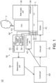
- FIG. 1 is a block diagram showing a functional configuration of a spray device 10 according to a first embodiment.
- the spray device 10 is a device that atomizes and sprays a liquid 1.
- the liquid 1 is hypochlorous acid water, tap water, etc.
- the spray device 10 is a humidifier.
- the spray device 10 includes a holding part 20, a water supply part 30, a spray part 40, a detection part 50, a control part 60, and a drive part 70.
- the holding part 20 is capable of holding the liquid 1 inside the holding part 20.
- the liquid 1 may be held inside the holding part 20.
- the holding part 20 is a container capable of storing the liquid 1.
- the holding part 20 is a water tank.
- the water supply part 30 holds the liquid 1 and supplies the held liquid 1 to the holding part 20.
- the water supply part 30 is a water supply tank.
- the spray part 40 atomizes and sprays the liquid 1 held in the holding part 20. In other words, the spray part 40 sprays the liquid 1 in a mist form.
- the spray part 40 includes a vibrator 41, an air blowing part 42, and a duct 43.
- the vibrator 41 vibrates and atomizes the liquid 1. Specifically, with the vibrator 41 vibrating, the vibrator 41 vibrates and atomizes the liquid 1 held in the holding part 20. For example, the vibrator 41 is immersed in the liquid 1.
- the vibrator 41 may be provided at a position capable of vibrating and atomizing the liquid 1.
- the vibrator 41 is an ultrasonic vibrator.
- the vibrator 41 is a piezoelectric vibrator.
- the air blowing part 42 blows air to the liquid 1 atomized by the vibrator 41.
- the air blowing part 42 generates air to hit the liquid 1 atomized by the vibrator 41.
- the liquid 1 atomized by the vibrator 41 is carried away by the air generated by the air blowing part 42.
- the air blowing part 42 may also blow air to the vibrator 41. Accordingly, it is possible to suppress an increase in temperature of the vibrator 41.
- the liquid 1 is hypochlorous acid water
- the duct 43 discharges the liquid 1 atomized by the vibrator 41 to outside of the spray device 10.
- the liquid 1 atomized by the vibrator 41 flows through the inside of the duct 43 with the air generated by the air blowing part 42 and is discharged from the duct 43 to outside of the spray device 10. In this manner, the spray device 10 sprays the liquid 1 in a mist form from the duct 43.
- the detection part 50 detects a liquid level of the liquid 1 held in the holding part 20. Further, in this embodiment, the detection part 50 detects a type of the liquid held in the holding part 20. Further, in this embodiment, the detection part 50 detects a state of the liquid 1 held in the holding part 20. Further, in this embodiment, the detection part 50 includes a first electrode 51, a second electrode 52, an application part 53, and a measurement part 54.
- the first electrode 51 and the second electrode 52 are provided inside the holding part 20.
- the first electrode 51 and the second electrode 52 are provided at a position at which a current value (resistance value) between the first electrode 51 and the second electrode 52 in the case where a voltage is applied between the first electrode 51 and the second electrode 52 changes according to the liquid level of the liquid 1 held in the holding part 20.
- the first electrode 51 and the second electrode 52 are provided at a position immersed in the liquid 1 in the case where a predetermined amount or more of the liquid 1 is held in the holding part 20.
- the current value (resistance value) between the first electrode 51 and the second electrode 52 in the case where a voltage is applied between the first electrode 51 and the second electrode 52 changes as the liquid level of the liquid 1 held in the holding part 20 changes.
- the liquid level can be detected based on the current value (the resistance value).
- the current value (resistance value) between the first electrode 51 and the second electrode 52 in the case where a voltage is applied between the first electrode 51 and the second electrode 52 changes according to the type of the liquid 1 held in the holding part 20.
- the type of the liquid 1 can be detected based on the current value (the resistance value).
- the current value (resistance value) between the first electrode 51 and the second electrode 52 in the case where a voltage is applied between the first electrode 51 and the second electrode 52 changes according to the state of the liquid 1 held in the holding part 20.
- the state of the liquid 1 can be detected based on the current value (the resistance value).
- each of the first electrode 51 and the second electrode 52 is an electrode rod.
- the application part 53 applies a first voltage between the first electrode 51 and the second electrode 52 with the first electrode 51 as the anode and the second electrode 52 as the cathode, and then the application part 53 applies a second voltage between the first electrode 51 and the second electrode 52 with the first electrode 51 as the cathode and the second electrode 52 as the anode.
- the application part 53 includes a first power supply 55 and a second power supply 56.
- the first power supply 55 is connected to the first electrode 51.
- the second power supply 56 is connected to the second electrode 52.
- the first electrode 51 becomes the anode, and the second electrode 52 becomes the cathode.
- the potential of the first electrode 51 is lower than the potential of the second electrode 52, the first electrode 51 becomes the cathode, and the second electrode 52 becomes the anode.
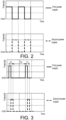
- FIG. 2 is a graph showing an example of the potentials of the first electrode 51 and the second electrode 52 of the spray device 10 in FIG. 1 .
- FIG. 3 is a graph showing another example of the potentials of the first electrode 51 and the second electrode 52 of the spray device 10 in FIG. 1 .
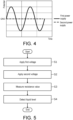
- FIG. 4 is a graph showing still another example of the potentials of the first electrode 51 and the second electrode 52 of the spray device 10 in FIG. 1 .
- the potential of the first electrode 51 is indicated by thick solid lines
- the potential of the second electrode 52 is indicated by thick broken lines.
- the first electrode 51 becomes the anode and the second electrode 52 becomes the cathode.
- the first power supply 55 controls the potential of the first electrode 51 to be GND and the second power supply 56 controls the potential of the second electrode 52 to be a potential higher than GND
- the first electrode 51 becomes the cathode and the second electrode 52 becomes the anode.
- the first electrode 51 becomes the anode and the second electrode 52 becomes the cathode.
- the first power supply 55 controls the potential of the first electrode 51 to be a potential higher than GND and the second power supply 56 controls the potential of the second electrode 52 to be GND
- the first electrode 51 becomes the anode and the second electrode 52 becomes the cathode.
- the first power supply 55 controls the potential of the first electrode 51 to be a potential lower than GND
- the second power supply 56 controls the potential of the second electrode 52 to be GND
- the first electrode 51 becomes the cathode and the second electrode 52 becomes the anode.
- the application part 53 applies the second voltage such that the waveform of the second voltage is an inverted waveform of the waveform of the first voltage.
- the magnitude and waveform of the potential of the first electrode 51 over a time in which the first electrode 51 is the anode and the second electrode 52 is the cathode are made consistent with the magnitude and waveform of the potential of the second electrode 52 over a time in which the first electrode 51 is the cathode and the second electrode 52 is the anode.
- the magnitude and waveform of the potential of the second electrode 52 over a time in which the first electrode 51 is the anode and the second electrode 52 is the cathode are made consistent with the magnitude and waveform of the potential of the first electrode 51 over a time in which the first electrode 51 is the cathode and the second electrode 52 is the anode. Accordingly, the waveform of the second voltage becomes an inverted waveform of the waveform of the first voltage.
- the waveform of the potential of the first electrode 51 over a time in which the first electrode 51 is the cathode and the second electrode 52 is the anode is set to be a waveform obtained by inverting, with respect to GND as the reference, the waveform of the potential of the first electrode 51 over a time in which the first electrode 51 is the anode and the second electrode 52 is the cathode. Accordingly, the waveform of the second voltage becomes an inverted waveform of the waveform of the first voltage.
- the application part 53 intermittently performs an operation of applying the first voltage and then applying the second voltage.
- the application part 53 applies the first voltage and then applies the second voltage, and subsequently, after a time interval, the application part 53 applies the first voltage and then applies the second voltage.
- the first power supply 55 controls the potential of the first electrode 51 to be a potential higher than GND and the second power supply 56 controls the potential of the second electrode 52 to be GND
- the first power supply 55 controls the potential of the first electrode 51 to be GND
- the second power supply 56 controls the potential of the second electrode 52 to be a potential higher than GND.
- the first power supply 55 controls the potential of the first electrode 51 to be GND
- the second power supply 56 controls the potential of the second electrode 52 to be GND.
- the first power supply 55 controls the potential of the first electrode 51 to be a potential higher than GND and the second power supply 56 controls the potential of the second electrode 52 to be GND
- the first power supply 55 controls the potential of the first electrode 51 to be GND
- the second power supply 56 controls the potential of the second electrode 52 to be a potential higher than GND.
- the first voltage is applied and then the second voltage is applied, and subsequently, after a time interval, the first voltage is applied and then the second voltage is applied.
- the application part 53 may also continuously perform the operation of applying the first voltage and then applying the second voltage.
- the application part 53 applies the first voltage and the second voltage in succession.
- the first power supply 55 continuously changes the potential of the first electrode 51 between a potential higher than GND and GND
- the second power supply 56 continuously changes the potential of the second electrode 52 between GND and a potential higher than GND. Accordingly, the first voltage and the second voltage are applied in succession.
- the second power supply 56 keeps the potential of the second electrode 52 at GND, and the first power supply 55 continuously changes the potential of the first electrode 51 between a potential higher than GND and a potential lower than GND. Accordingly, the first voltage and the second voltage are applied in succession.
- the application part 53 intermittently performs the operation of applying the first voltage and the second voltage in succession at a time interval longer than a time of applying the first voltage and the second voltage in succession.
- the application part 53 applies the first voltage and the second voltage in succession, and subsequently, after a time interval longer than the time of applying the first voltage and the second voltage in succession, the application part 53 applies the first voltage and the second voltage in succession.
- the first power supply 55 continuously changes the potential of the first electrode 51 between a potential higher than GND and GND
- the second power supply 56 continuously changes the potential of the second electrode 52 between GND and a potential higher than GND. Accordingly, the first voltage and the second voltage are applied in succession.
- the first power supply 55 controls the potential of the first electrode 51 to be GND
- the second power supply 56 controls the potential of the second electrode 52 to be GND. Accordingly, the first voltage and the second voltage are not applied.
- the first power supply 55 continuously changes the potential of the first electrode 51 between a potential higher than GND and GND
- the second power supply 56 continuously changes the potential of the second electrode 52 between GND and a potential higher than GND.
- the first voltage and the second voltage are applied in succession. For example, by doing so, the first voltage and the second voltage are applied in succession, and subsequently, after a time interval longer than the time of applying the first voltage and the second voltage in succession, the first voltage and the second voltage are applied in succession.
- a time over which the potential of the first electrode 51 is higher than GND and the potential of the second electrode 52 is GND is equal to a time over which the potential of the first electrode 51 is GND and the potential of the second electrode 52 is higher than GND.
- the application part 53 may continuously perform the operation of applying the first voltage and the second voltage in succession.
- the application part 53 does not apply the first voltage and the second voltage when the liquid is not being sprayed by the spray part 40. Specifically, for example, the application part 53 does not apply the first voltage and the second voltage when the vibrator 41 itself is not vibrating and the vibrator 41 is not vibrating the liquid 1.
- the measurement part 54 measures at least one of a current value and a resistance value between the first electrode 51 and the second electrode 52 in the case where a voltage is applied between the first electrode 51 and the second electrode 52. Specifically, for example, the measurement part 54 measures at least one of the current value and the resistance value between the first electrode 51 and the second electrode 52 in the case where the first voltage is applied between the first electrode 51 and the second electrode 52. Further, for example, the measurement part 54 measures at least one of the current value and the resistance value between the first electrode 51 and the second electrode 52 in the case where the second voltage is applied between the first electrode 51 and the second electrode 52.
- the measurement part 54 may be an ammeter and measures a current value. Further, for example, the measurement part 54 may be a resistance meter and measures a resistance value. In addition, for example, the measurement part 54 may measure an impedance.
- the measurement part 54 measures a voltage at a resistor end of a fixed resistor (not shown) provided between the first power supply 55 and the first electrode 51 to measure a current value (resistance value) between the first electrode 51 and the second electrode 52.
- the fixed resistor is built into the application part 53.
- the detection part 50 measures at least one of a current value and a resistance value using the first electrode 51 and the second electrode 52, and detects a liquid level of the liquid 1 held in the holding part 20 based on at least one of the current value and the resistance value. For example, the detection part 50 detects whether the liquid level of the liquid 1 held in the holding part 20 is equal to or higher than a predetermined height by comparing at least one of the current value and the resistance value with a threshold value.
- the detection part 50 measures at least one of a current value and a resistance value using the first electrode 51 and the second electrode 52, and detects a type of the liquid 1 held in the holding part 20 based on at least one of the current value and the resistance value. For example, the detection part 50 detects whether the type of the liquid 1 held in the holding part 20 is hypochlorous acid water or not, whether it is tap water or not, etc., by comparing at least one of the current value and the resistance value with a threshold value.
- the detection part 50 measures at least one of a current value and a resistance value using the first electrode 51 and the second electrode 52, and detects a state of the liquid 1 held in the holding part 20 based on at least one of the current value and the resistance value. For example, in the case where the liquid 1 is hypochlorous acid water, the detection part 50 detects whether a concentration of the liquid 1 held in the holding part 20 is equal to or greater than a predetermined concentration by comparing at least one of the current value and the resistance value with a threshold value.
- the control part 60 controls the spray part 40.
- the control part 60 controls the spray part 40 based on the liquid level of the liquid 1 detected by the detection part 50. Specifically, for example, the control part 60 controls the vibrator 41 and the air blowing part 42 based on the liquid level of the liquid 1 detected by the detection part 50. For example, in the case where the liquid level of the liquid 1 detected by the detection part 50 is lower than the predetermined height, the control part 60 controls the spray part 40 so as not to spray the liquid 1. Specifically, for example, in the case where the liquid level of the liquid 1 detected by the detection part 50 is lower than the predetermined height, the control part 60 controls the vibrator 41 such that the vibrator 41 does not vibrate, and controls the air blowing part 42 such that the air blowing part 42 does not blow air.
- control part 60 drives the air blowing part 42 in conjunction with the vibrator 41.
- the control part 60 drives the air blowing part 42 when the vibrator 41 is being vibrated, and the control part 60 does not drive the air blowing part 42 when the vibrator 41 is not being vibrated. In this manner, for example, the control part 60 stops air blowing of the air blowing part 42 when vibration of the vibrator 41 is stopped.
- the spray amount of the liquid 1 required to be sprayed is a spray amount of the liquid 1 required to be sprayed per predetermined time, and is inputted by a user or the like.
- the atomization rate in the case of vibrating the vibrator 41 at a first vibration frequency is 400 mL/h
- the atomization rate in the case of vibrating the vibrator 41 at a second vibration frequency is 100 mL/h
- the atomization rate of the liquid 1 is measured in advance and stored in the spray device 10.
- control part 60 controls the spray part 40 based on at least one of the type of the liquid 1 and the state of the liquid 1 detected by the detection part 50.
- the control part 60 controls the spray part 40 such that the spray amount per unit time does not exceed a predetermined amount. Further, for example, in the case where the type of the liquid 1 detected by the detection part 50 is salt water or bleach, the control part 60 controls the spray part 40 so as not to spray the liquid 1. Further, for example, in the case where the type of the liquid 1 detected by the detection part 50 is hypochlorous acid water and the concentration of the hypochlorous acid water is lower than the predetermined concentration, the control part 60 controls the spray part 40 so as not to spray the liquid 1.
- the drive part 70 drives the vibrator 41.
- the drive part 70 is a circuit that vibrates the vibrator 41.
- FIG. 5 is a flowchart showing an example of an operation of the spray device 10 in FIG. 1 .
- the operation includes a detection step (steps S1 to S4) of detecting the liquid level of the liquid 1 held in the holding part 20.
- the application part 53 applies a first voltage between the first electrode 51 and the second electrode 52 (step S1). Specifically, for example, as described above, the application part 53 applies the first voltage.
- the application part 53 After applying the first voltage, taking the first electrode 51 as the cathode and the second electrode 52 as the anode, the application part 53 applies a second voltage between the first electrode 51 and the second electrode 52 (step S2). Specifically, for example, as described above, the application part 53 applies the second voltage.
- the measurement part 54 measures a resistance value (step S3).
- the measurement part 54 measures a resistance value between the first electrode 51 and the second electrode 52 in the case where the first voltage is applied between the first electrode 51 and the second electrode 52.
- the measurement part 54 measures a resistance value between the first electrode 51 and the second electrode 52 in the case where the second voltage is applied between the first electrode 51 and the second electrode 52.
- the measurement part 54 measures the resistance value between the first electrode 51 and the second electrode 52.
- the measurement part 54 may measure a current value instead of the resistance value.
- the detection part 50 detects a liquid level of the liquid 1 held in the holding part 20 (step S4).
- the liquid 1 is hypochlorous acid water
- a resistance value between the first electrode 51 and the second electrode 52 in the case where a voltage is applied between the first electrode 51 and the second electrode 52 is measured in advance as a first threshold value.
- a resistance value between the first electrode 51 and the second electrode 52 in the case where a voltage is applied between the first electrode 51 and the second electrode 52 is measured in advance as a second threshold value.
- the first threshold value and the second threshold value are stored in the spray device 10.
- the detection part 50 detects that the liquid level of the liquid 1 held in the holding part 20 is the predetermined liquid level or higher in the case where the measured resistance value is equal to or less than the first threshold value. Further, for example, the detection part 50 detects that the liquid level of the liquid 1 held in the holding part 20 has dropped below the predetermined liquid level in the case where the measured resistance value is greater than the first threshold value.
- the detection part 50 further detects at least one of the type and the state of the liquid 1 held in the holding part 20. For example, in the case where the measured resistance value is less than the second threshold value, the detection part 50 detects that the type of the liquid 1 held in the holding part 20 is a water incompatible with the spray device 10, or that the state of the liquid 1 held in the holding part 20 is abnormal. Further, for example, in the case where the measured resistance value is equal to or greater than the second threshold value and equal to or less than the first threshold value, the detection part 50 detects that the type of the liquid 1 held in the holding part 20 is hypochlorous acid water, and that the state of the liquid 1 held in the holding part 20 is normal.
- FIG. 6 is a flowchart showing an example of another operation of the spray device 10 in FIG. 1 .
- the measurement part 54 measures an impedance (step S11). For example, the measurement part 54 measures an impedance between the first electrode 51 and the second electrode 52 in the case where the first voltage is applied between the first electrode 51 and the second electrode 52. Further, for example, the measurement part 54 measures an impedance between the first electrode 51 and the second electrode 52 in the case where the second voltage is applied between the first electrode 51 and the second electrode 52.
- the control part 60 determines at least one of a liquid level of the liquid 1, a type of the liquid 1, and a state of the liquid 1 held in the holding part 20 based on the impedance measured by the measurement part 54 (step S12). Specifically, the control part 60 determines at least one of the liquid level of the liquid 1, the type of the liquid 1, and the state of the liquid 1 held in the holding part 20 based on a value of the impedance measured by the measurement part 54.
- the control part 60 controls the spray part 40 based on at least one of the liquid level of the liquid 1, the type of the liquid 1, and the state of the liquid 1 held in the holding part 20 (step S13).
- control part 60 sprays the liquid 1 from the spray part 40 while managing the spray amount.
- the control part 60 constantly sprays the liquid 1 from the spray part 40 and constantly drives the vibrator 41 and the air blowing part 42. Further, for example, in the case where the type of the liquid 1 held in the holding part 20 is tap water and the spray device 10 is a device incapable of using tap water, the control part 60 does not drive the spray part 40.
- control part 60 does not drive the spray part 40.
- control part 60 does not drive the vibrator 41 and the air blowing part 42.
- the control part 60 displays a request for water supply to the holding part 20 on a monitor (not shown) or the like.
- the control part 60 does not drive the spray part 40.
- the control part 60 displays a warning and a request for replacing the liquid 1 held in the holding part 20 on a monitor (not shown) or the like.
- the control part 60 does not drive the spray part 40.
- the control part 60 displays a warning and a request for replacing the liquid 1 held in the holding part 20 on a monitor (not shown) or the like.
- FIG. 7 is a flowchart showing an example of another operation of the spray device 10 in FIG. 1 .
- the measurement part 54 measures a resistance value (step S21). For example, the measurement part 54 measures a resistance value between the first electrode 51 and the second electrode 52 in the case where the first voltage is applied between the first electrode 51 and the second electrode 52. Further, for example, the measurement part 54 measures a resistance value between the first electrode 51 and the second electrode 52 in the case where the second voltage is applied between the first electrode 51 and the second electrode 52.
- the control part 60 determines at least one of a liquid level of the liquid 1, a type of the liquid 1, and a state of the liquid 1 held in the holding part 20 based on the resistance value measured by measurement part 54 (step S22).
- the control part 60 controls the spray part 40 based on at least one of the liquid level of the liquid 1, the type of the liquid 1, and the state of the liquid 1 held in the holding part 20 (step S23).
- the control part 60 determines that the type of the liquid 1 is incompatible with the spray device 10 and does not drive the spray part 40. For example, in this case, the control part 60 displays a request for replacing the liquid 1 held in the holding part 20 on a monitor (not shown) or the like.
- the control part 60 determines that the liquid 1 is normal hypochlorous acid water and drives the spray part 40.
- the control part 60 determines that the liquid 1 is not held in the holding part 20 and does not drive the spray part 40. For example, in this case, the control part 60 displays a request for water supply to the holding part 20 on a monitor (not shown) or the like.
- the spray device 10 since the liquid level of the liquid 1 held in the holding part 20 can be detected, it is possible to suppress vibration of the vibrator 41 and suppress damage of the vibrator 41 in the case where the liquid 1 is not held in the holding part 20.
- the spray device 10 since the first voltage is applied and then the second voltage is applied, it is possible to suppress occurrence of electrolytic corrosion on the first electrode 51 and the second electrode 52 and melting of the first electrode 51 and the second electrode 52, and it is possible to suppress mixing of melted metal into the liquid 1. Accordingly, in the case where the liquid 1 is hypochlorous acid water, it is possible to suppress a decrease in the efficacy of the hypochlorous acid water.
- a spray device 10 includes a holding part 20, a spray part 40, and a detection part 50.
- the holding part 20 is capable of holding a liquid 1 inside the holding part 20.
- the spray part 40 atomizes and sprays the liquid 1 held in the holding part 20.
- the detection part 50 detects a liquid level of the liquid 1 held in the holding part 20.
- the detection part 50 includes a first electrode 51, a second electrode 52, and an application part 53.
- the first electrode 51 and the second electrode 52 are provided inside the holding part 20.
- the application part 53 applies a first voltage between the first electrode 51 and the second electrode 52 with the first electrode 51 as an anode and the second electrode 52 as a cathode, and then applies a second voltage between the first electrode 51 and the second electrode 52 with the first electrode 51 as the cathode and the second electrode 52 as the anode.
- the detection part 50 which detects the liquid level of the liquid 1 held in the holding part 20, it is possible to detect the liquid level of the liquid 1. Further, since the detection part 50 includes the application part 53 which applies the first voltage between the first electrode 51 and the second electrode 52 with the first electrode 51 as the anode and the second electrode 52 as the cathode, and then applies the second voltage between the first electrode 51 and the second electrode 52 with the first electrode 51 as the cathode and the second electrode 52 as the anode, it is possible to suppress deterioration of the electrodes. In this manner, it is possible to detect the liquid level of the liquid 1 while suppressing deterioration of the electrodes.
- the application part 53 applies the second voltage such that a waveform of the second voltage is an inverted waveform of a waveform of the first voltage.
- the application part 53 intermittently performs an operation of applying the first voltage and then applying the second voltage.
- the application part 53 applies the first voltage and the second voltage in succession.
- the application part 53 intermittently performs an operation of applying the first voltage and the second voltage in succession at a time interval longer than a time of applying the first voltage and the second voltage in succession.
- the application part 53 does not apply the first voltage and the second voltage in a case where the liquid 1 is not being sprayed by the spray part 40.
- the spray part 40 includes a vibrator 41 which vibrates and atomizes the liquid 1, and an air blowing part 42 which blows air to the liquid 1 atomized by the vibrator 41.
- the spray device 10 further includes a control part 60 which controls the spray part 40.
- the control part 60 drives the air blowing part 42 in conjunction with the vibrator 41.
- the air blowing part 42 can be driven when the vibrator 41 is vibrating, it is possible to efficiently spray the liquid 1 held in the holding part 20.
- control part 60 stops air blowing of the air blowing part 42 in a case where vibration of the vibrator 41 has stopped.
- the liquid 1 is hypochlorous acid water.
- the spray device 10 further includes a control part 60 which controls the spray part 40 based on the liquid level detected by the detection part 50.
- the detection part 50 further detects at least one of a type and a state of the liquid 1 held in the holding part 20.
- the control part 60 controls the spray part 40 based on at least one of the type and the state detected by the detection part 50.
- a control method is a control method of a spray device 10.
- the spray device 10 includes a holding part 20, a spray part 40, a first electrode 51, and a second electrode 52.
- the holding part 20 is capable of holding a liquid 1 inside the holding part 20.
- the spray part 40 atomizes and sprays the liquid 1 held in the holding part 20.
- the first electrode 51 and the second electrode 52 are provided inside the holding part 20.
- the control method includes a detection step of detecting a liquid level of the liquid 1 held in the holding part 20.
- a first voltage is applied between the first electrode 51 and the second electrode 52 with the first electrode 51 as an anode and the second electrode 52 as a cathode (step S1), and after the first voltage is applied, a second voltage is applied between the first electrode 51 and the second electrode 52 with the first electrode 51 as the cathode and the second electrode 52 as the anode (step S2).
- FIG. 8 is a block diagram showing a functional configuration of a spray device 10a according to a second embodiment.
- the spray device 10a includes a holding part 20a, a spray part 40a, a detection part 50, a control part 60, and a drive part 70.
- the spray part 40a includes a vibrator 41a, an air blowing part 42, and a water suction part 44a.
- a portion of the water suction part 44a is immersed in the liquid 1 held in the holding part 20a, and the water suction part 44a sucks up the liquid 1 held in the holding part 20a.
- the water suction part 44a is a tubular member.
- the vibrator 41a is connected to the water suction part 44a, vibrates and atomizes the liquid 1 sucked up by the water suction part 44a, and discharges the atomized liquid 1.
- the vibrator 41a vibrates and atomizes the liquid 1 inside the vibrator 41a, and discharges the liquid in a mist form from a hole formed at the vibrator 41a.
- FIG. 9 is a block diagram showing a functional configuration of a spray device 10b according to a third embodiment.
- the spray device 10b mainly differs from the spray device 10a in that the spray device 10b includes a spray part 40b instead of the spray part 40a.
- the spray part 40b mainly differs from the spray part 40a in that the spray part 40b does not include the air blowing part 42.
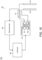
- FIG. 10 is a block diagram showing a functional configuration of a spray device 10c according to a fourth embodiment.
- illustration of the holding part 20 and the like is omitted.
- the spray device 10c mainly differs from the spray device 10 in that a fixed resistor 57 is provided outside the application part 53.
- the measurement part 54 measures at least one of a resistance value and a current value between the first electrode 51 and the second electrode 52 by measuring a voltage across two ends of the fixed resistor 57.
- the control part 60 controls the application part 53 based on a measurement result of the measurement part 54.
- each of the above devices may be configured as a computer system composed of a microprocessor, a ROM, a RAM, a hard disk drive, a display unit, a keyboard, a mouse, and the like.
- Computer programs are stored in the RAM or the hard disk drive.
- Each device achieves its function by operation of the microprocessor according to the computer program.
- the computer program is configured by combining a plurality of instruction codes indicating commands to a computer in order to achieve a predetermined function.
- a system LSI is a super-multifunctional LSI manufactured by integrating a plurality of components on one chip, and, for example, includes a computer system configured to include a microprocessor, a ROM, a RAM, and the like.
- the computer program is stored in the ROM.
- the system LSI achieves its function by operation of the microprocessor according to the computer program.
- each of the above devices may be composed of an IC card or a separate module that may be attached to and detached from each device.
- the IC card or the module is a computer system composed of a microprocessor, a ROM, a RAM, and the like.
- the IC card or the module may include the above super-multifunctional LSI.
- the IC card or the module achieves its function by operation of the microprocessor according to the computer program.
- the IC card or the module may have tamper resistance.
- the disclosure may be the methods shown above. Further, the disclosure may be computer programs that realize these methods by a computer, or may be digital signals composed of the above computer programs.
- the disclosure may record the above computer program or the above digital signal to a non-transitory computer-readable recording medium, such as a flexible disk, a hard disk, a CD-ROM, an MO, a DVD, a DVD-ROM, a DVD-RAM, a BD (Blu-ray (registered trademark) disc), a semiconductor memory, or the like. Further, it may be the digital signal recorded on these non-transitory recording media.
- a non-transitory computer-readable recording medium such as a flexible disk, a hard disk, a CD-ROM, an MO, a DVD, a DVD-ROM, a DVD-RAM, a BD (Blu-ray (registered trademark) disc), a semiconductor memory, or the like.
- the disclosure may transmit the computer program or the digital signal via a telecommunication line, a wireless or wired communication line, a network represented by the Internet, data broadcasting, or the like.
- the disclosure may be a computer system including a microprocessor and a memory, the memory may store the above computer program, and the microprocessor may operate according to the computer program.
- the spray device according to the disclosure may be applied as a device that sprays a liquid in a mist form.
Landscapes
- Engineering & Computer Science (AREA)
- Chemical & Material Sciences (AREA)
- General Engineering & Computer Science (AREA)
- Mechanical Engineering (AREA)
- Combustion & Propulsion (AREA)
- Health & Medical Sciences (AREA)
- Physics & Mathematics (AREA)
- Epidemiology (AREA)
- General Health & Medical Sciences (AREA)
- Public Health (AREA)
- Veterinary Medicine (AREA)
- Animal Behavior & Ethology (AREA)
- Life Sciences & Earth Sciences (AREA)
- General Physics & Mathematics (AREA)
- Fluid Mechanics (AREA)
- Thermal Sciences (AREA)
- Special Spraying Apparatus (AREA)
- Disinfection, Sterilisation Or Deodorisation Of Air (AREA)
- Spray Control Apparatus (AREA)
- Electrostatic Spraying Apparatus (AREA)
Abstract
Description
- The disclosure relates to a spray device and the like for spraying a liquid.
- A spray device and the like for spraying a liquid are conventionally known. As an example of the spray device,
Patent Document 1 discloses an air purifier in which a first electrode is energized as a positive electrode and a second electrode is energized as a negative electrode, and then the first electrode is energized as the negative electrode and the second electrode is energized as the positive electrode. - [Patent Document 1]
Japanese Patent Application Laid-Open No. 2012-075667 - However, in the air purifier of
Patent Document 1, it is not assumed to detect a liquid level of the liquid using the first electrode and the second electrode, and there is a problem that the liquid level of the liquid cannot be detected. - The disclosure has been made to solve the above problem, and an objective thereof is to provide a spray device and the like capable of detecting a liquid level of a liquid while suppressing deterioration of electrodes.
- To achieve the above objective, a spray device according to an embodiment of the disclosure includes a holding part, a spray part, and a detection part. The holding part is capable of holding a liquid inside the holding part. The spray part atomizes and sprays the liquid held in the holding part. The detection part detects a liquid level of the liquid held in the holding part. The detection part includes a first electrode, a second electrode, and an application part. The first electrode and the second electrode are provided inside the holding part. The application part applies a first voltage between the first electrode and the second electrode with the first electrode as an anode and the second electrode as a cathode, and then applies a second voltage between the first electrode and the second electrode with the first electrode as the cathode and the second electrode as the anode.
- According to this embodiment, with the detection part which detects the liquid level of the liquid held in the holding part, it is possible to detect the liquid level of the liquid. Further, since the detection part includes the application part which applies the first voltage between the first electrode and the second electrode with the first electrode as the anode and the second electrode as the cathode, and then applies the second voltage between the first electrode and the second electrode with the first electrode as the cathode and the second electrode as the anode, it is possible to suppress deterioration of the electrodes. In this manner, it is possible to detect the liquid level of the liquid while suppressing deterioration of the electrodes.
- For example, in the spray device according to an embodiment of the disclosure, the application part may apply the second voltage such that a waveform of the second voltage is an inverted waveform of a waveform of the first voltage.
- According to this embodiment, it is possible to detect the liquid level of the liquid while further suppressing deterioration of the electrodes.
- For example, in the spray device according to an embodiment of the disclosure, the application part may intermittently perform an operation of applying the first voltage and then applying the second voltage.
- According to this embodiment, it is possible to repeatedly detect the liquid level of the liquid while further suppressing deterioration of the electrodes.
- For example, in the spray device according to an embodiment of the disclosure, the application part may apply the first voltage and the second voltage in succession.
- According to this embodiment, it is possible to detect the liquid level of the liquid while further suppressing deterioration of the electrodes.
- For example, in the spray device according to an embodiment of the disclosure, the application part may intermittently perform an operation of applying the first voltage and the second voltage in succession at a time interval longer than a time of applying the first voltage and the second voltage in succession.
- According to this embodiment, it is possible to repeatedly detect the liquid level of the liquid while further suppressing deterioration of the electrodes.
- For example, in the spray device according to an embodiment of the disclosure, the application part may not apply the first voltage and the second voltage in a case where the liquid is not being sprayed by the spray part.
- According to this embodiment, it is possible to detect the liquid level of the liquid while further suppressing deterioration of the electrodes.
- For example, in the spray device according to an embodiment of the disclosure, the spray part may include a vibrator which vibrates and atomizes the liquid, and an air blowing part which blows air to the liquid atomized by the vibrator.
- According to this embodiment, it is possible to detect the liquid level of the liquid while suppressing deterioration of the electrodes, and it is possible to easily spray the liquid held in the holding part.
- For example, the spray device according to an embodiment of the disclosure may further include a control part which controls the spray part. The control part may drive the air blowing part in conjunction with the vibrator.
- According to this embodiment, since the air blowing part can be driven when the vibrator is vibrating, it is possible to efficiently spray the liquid held in the holding part.
- For example, in the spray device according to an embodiment of the disclosure, the control part may stop air blowing of the air blowing part in a case where vibration of the vibrator has stopped.
- According to this embodiment, it is possible to suppress air blowing of the air blowing part when the liquid is not atomized and air blowing is not required.
- For example, in the spray device according to an embodiment of the disclosure, taking a spray amount of the liquid required to be sprayed as A, an atomization rate of the liquid due to vibration of the vibrator as B, and a vibration time of the vibrator as C, the control part may vibrate the vibrator based on the spray amount such that A = B × C is satisfied and the atomization rate is increased and the vibration time is shortened.
- According to this embodiment, since it is possible to shorten the time of blowing air to the liquid in the mist form, it is possible to suppress degradation of the liquid.
- For example, in the spray device according to an embodiment of the disclosure, the liquid may be hypochlorous acid water.
- According to this embodiment, it is possible to suppress degradation of hypochlorous acid water.
- For example, the spray device according to an embodiment of the disclosure may further include a control part which controls the spray part based on the liquid level detected by the detection part.
- According to this embodiment, it is possible to control spray of the liquid based on the liquid level detected by the detection part.
- For example, in the spray device according to an embodiment of the disclosure, the detection part may further detect at least one of a type and a state of the liquid held in the holding part. The control part may control the spray part based on at least one of the type and the state detected by the detection part.
- According to this embodiment, it is possible to control spray of the liquid based on at least one of the type and the state of the liquid detected by the detection part.
- To achieve the above objective, a control method according to an embodiment of the disclosure is a control method of a spray device. The spray device includes a holding part, a spray part, a first electrode, and a second electrode. The holding part is capable of holding a liquid inside the holding part. The spray part atomizes and sprays the liquid held in the holding part. The first electrode and the second electrode are provided inside the holding part. The control method includes a detection step of detecting a liquid level of the liquid held in the holding part. In the detection step, a first voltage is applied between the first electrode and the second electrode with the first electrode as an anode and the second electrode as a cathode, and after the first voltage is applied, a second voltage is applied between the first electrode and the second electrode with the first electrode as the cathode and the second electrode as the anode.
- According to this embodiment, the same effect as the spray device described above is achieved.
- In addition, the disclosure may be realized not only as a spray device including such a characteristic processing part, but also as a control method including steps of a process performed by the characteristic processing part included in the spray device. Further, the disclosure may also be realized as a program for causing a computer to function as the characteristic processing part included in the spray device or as a program that causes a computer to execute the characteristic steps included in the control method. Obviously, such a program may be distributed via a non-transitory computer-readable recording medium such as a compact disc-read only memory (CD-ROM) or a communication network such as the Internet.
- According to the spray device and the like according to an embodiment of the disclosure, it is possible to detect the liquid level of the liquid while suppressing deterioration of the electrodes.
-
-
FIG. 1 is a block diagram showing a functional configuration of a spray device according to a first embodiment. -
FIG. 2 is a graph showing an example of potentials of a first electrode and a second electrode of the spray device inFIG. 1 . -
FIG. 3 is a graph showing another example of the potentials of the first electrode and the second electrode of the spray device inFIG. 1 . -
FIG. 4 is a graph showing still another example of the potentials of the first electrode and the second electrode of the spray device inFIG. 1 . -
FIG. 5 is a flowchart showing an example of an operation of the spray device inFIG. 1 . -
FIG. 6 is a flowchart showing an example of another operation of the spray device inFIG. 1 . -
FIG. 7 is a flowchart showing an example of still another operation of the spray device inFIG. 1 . -
FIG. 8 is a block diagram showing a functional configuration of a spray device according to a second embodiment. -
FIG. 9 is a block diagram showing a functional configuration of a spray device according to a third embodiment. -
FIG. 10 is a block diagram showing a functional configuration of a spray device according to a fourth embodiment. - Hereinafter, embodiments of the disclosure will be described in detail with reference to the drawings. The embodiments described below all show comprehensive or specific examples. Numerical values, shapes, materials, components, arrangement positions and connections of the components, steps, the sequence of steps, etc. shown in the following embodiments are merely an example and are not intended to limit the disclosure. Further, among the components in the following embodiments, the components not described in the independent claims will be described as arbitrary components.
-
FIG. 1 is a block diagram showing a functional configuration of aspray device 10 according to a first embodiment. - The
spray device 10 is a device that atomizes and sprays aliquid 1. For example, theliquid 1 is hypochlorous acid water, tap water, etc. For example, thespray device 10 is a humidifier. As shown inFIG. 1 , thespray device 10 includes a holdingpart 20, awater supply part 30, aspray part 40, adetection part 50, acontrol part 60, and adrive part 70. - The holding
part 20 is capable of holding theliquid 1 inside the holdingpart 20. In other words, theliquid 1 may be held inside the holdingpart 20. For example, the holdingpart 20 is a container capable of storing theliquid 1. Specifically, for example, the holdingpart 20 is a water tank. - The
water supply part 30 holds theliquid 1 and supplies the held liquid 1 to the holdingpart 20. For example, thewater supply part 30 is a water supply tank. - The
spray part 40 atomizes and sprays theliquid 1 held in the holdingpart 20. In other words, thespray part 40 sprays theliquid 1 in a mist form. Thespray part 40 includes avibrator 41, anair blowing part 42, and aduct 43. - The
vibrator 41 vibrates and atomizes theliquid 1. Specifically, with thevibrator 41 vibrating, thevibrator 41 vibrates and atomizes the liquid 1 held in the holdingpart 20. For example, thevibrator 41 is immersed in theliquid 1. Thevibrator 41 may be provided at a position capable of vibrating and atomizing theliquid 1. For example, thevibrator 41 is an ultrasonic vibrator. Specifically, for example, thevibrator 41 is a piezoelectric vibrator. - The
air blowing part 42 blows air to theliquid 1 atomized by thevibrator 41. In other words, theair blowing part 42 generates air to hit the liquid 1 atomized by thevibrator 41. The liquid 1 atomized by thevibrator 41 is carried away by the air generated by theair blowing part 42. - For example, the
air blowing part 42 may also blow air to thevibrator 41. Accordingly, it is possible to suppress an increase in temperature of thevibrator 41. For example, in the case where theliquid 1 is hypochlorous acid water, it is possible to suppress an increase in temperature of the hypochlorous acid water and suppress acidification (deterioration) of the hypochlorous acid water. - The
duct 43 discharges theliquid 1 atomized by thevibrator 41 to outside of thespray device 10. In this embodiment, theliquid 1 atomized by thevibrator 41 flows through the inside of theduct 43 with the air generated by theair blowing part 42 and is discharged from theduct 43 to outside of thespray device 10. In this manner, thespray device 10 sprays theliquid 1 in a mist form from theduct 43. - The
detection part 50 detects a liquid level of the liquid 1 held in the holdingpart 20. Further, in this embodiment, thedetection part 50 detects a type of the liquid held in the holdingpart 20. Further, in this embodiment, thedetection part 50 detects a state of the liquid 1 held in the holdingpart 20. Further, in this embodiment, thedetection part 50 includes afirst electrode 51, asecond electrode 52, anapplication part 53, and ameasurement part 54. - The
first electrode 51 and thesecond electrode 52 are provided inside the holdingpart 20. Thefirst electrode 51 and thesecond electrode 52 are provided at a position at which a current value (resistance value) between thefirst electrode 51 and thesecond electrode 52 in the case where a voltage is applied between thefirst electrode 51 and thesecond electrode 52 changes according to the liquid level of the liquid 1 held in the holdingpart 20. For example, thefirst electrode 51 and thesecond electrode 52 are provided at a position immersed in theliquid 1 in the case where a predetermined amount or more of theliquid 1 is held in the holdingpart 20. The current value (resistance value) between thefirst electrode 51 and thesecond electrode 52 in the case where a voltage is applied between thefirst electrode 51 and thesecond electrode 52 changes as the liquid level of the liquid 1 held in the holdingpart 20 changes. Thus, the liquid level can be detected based on the current value (the resistance value). Further, for example, the current value (resistance value) between thefirst electrode 51 and thesecond electrode 52 in the case where a voltage is applied between thefirst electrode 51 and thesecond electrode 52 changes according to the type of the liquid 1 held in the holdingpart 20. Thus, the type of the liquid 1 can be detected based on the current value (the resistance value). Further, for example, the current value (resistance value) between thefirst electrode 51 and thesecond electrode 52 in the case where a voltage is applied between thefirst electrode 51 and thesecond electrode 52 changes according to the state of the liquid 1 held in the holdingpart 20. Thus, the state of the liquid 1 can be detected based on the current value (the resistance value). For example, each of thefirst electrode 51 and thesecond electrode 52 is an electrode rod. - The
application part 53 applies a first voltage between thefirst electrode 51 and thesecond electrode 52 with thefirst electrode 51 as the anode and thesecond electrode 52 as the cathode, and then theapplication part 53 applies a second voltage between thefirst electrode 51 and thesecond electrode 52 with thefirst electrode 51 as the cathode and thesecond electrode 52 as the anode. Theapplication part 53 includes afirst power supply 55 and asecond power supply 56. - The
first power supply 55 is connected to thefirst electrode 51. Thesecond power supply 56 is connected to thesecond electrode 52. In the case where the potential of thefirst electrode 51 is higher than the potential of thesecond electrode 52, thefirst electrode 51 becomes the anode, and thesecond electrode 52 becomes the cathode. In the case where the potential of thefirst electrode 51 is lower than the potential of thesecond electrode 52, thefirst electrode 51 becomes the cathode, and thesecond electrode 52 becomes the anode. -
FIG. 2 is a graph showing an example of the potentials of thefirst electrode 51 and thesecond electrode 52 of thespray device 10 inFIG. 1 .FIG. 3 is a graph showing another example of the potentials of thefirst electrode 51 and thesecond electrode 52 of thespray device 10 inFIG. 1 .FIG. 4 is a graph showing still another example of the potentials of thefirst electrode 51 and thesecond electrode 52 of thespray device 10 inFIG. 1 . InFIG. 2 to FIG. 4 , the potential of thefirst electrode 51 is indicated by thick solid lines, and the potential of thesecond electrode 52 is indicated by thick broken lines. - As shown in
FIG. 2 and FIG. 3 , for example, when thefirst power supply 55 controls the potential of thefirst electrode 51 to be a potential higher than GND and thesecond power supply 56 controls the potential of thesecond electrode 52 to be GND, thefirst electrode 51 becomes the anode and thesecond electrode 52 becomes the cathode. Further, for example, when thefirst power supply 55 controls the potential of thefirst electrode 51 to be GND and thesecond power supply 56 controls the potential of thesecond electrode 52 to be a potential higher than GND, thefirst electrode 51 becomes the cathode and thesecond electrode 52 becomes the anode. - As shown in
FIG. 4 , for example, when thefirst power supply 55 controls the potential of thefirst electrode 51 to be a potential higher than GND and thesecond power supply 56 controls the potential of thesecond electrode 52 to be GND, thefirst electrode 51 becomes the anode and thesecond electrode 52 becomes the cathode. Further, for example, when thefirst power supply 55 controls the potential of thefirst electrode 51 to be a potential lower than GND and thesecond power supply 56 controls the potential of thesecond electrode 52 to be GND, thefirst electrode 51 becomes the cathode and thesecond electrode 52 becomes the anode. - For example, the
application part 53 applies the second voltage such that the waveform of the second voltage is an inverted waveform of the waveform of the first voltage. - As shown in
FIG. 2 and FIG. 3 , for example, the magnitude and waveform of the potential of thefirst electrode 51 over a time in which thefirst electrode 51 is the anode and thesecond electrode 52 is the cathode are made consistent with the magnitude and waveform of the potential of thesecond electrode 52 over a time in which thefirst electrode 51 is the cathode and thesecond electrode 52 is the anode. Also, the magnitude and waveform of the potential of thesecond electrode 52 over a time in which thefirst electrode 51 is the anode and thesecond electrode 52 is the cathode are made consistent with the magnitude and waveform of the potential of thefirst electrode 51 over a time in which thefirst electrode 51 is the cathode and thesecond electrode 52 is the anode. Accordingly, the waveform of the second voltage becomes an inverted waveform of the waveform of the first voltage. - As shown in
FIG. 4 , for example, in the case where the potential of thesecond electrode 52 is set to GND and only the potential of thefirst electrode 51 is changed, the waveform of the potential of thefirst electrode 51 over a time in which thefirst electrode 51 is the cathode and thesecond electrode 52 is the anode is set to be a waveform obtained by inverting, with respect to GND as the reference, the waveform of the potential of thefirst electrode 51 over a time in which thefirst electrode 51 is the anode and thesecond electrode 52 is the cathode. Accordingly, the waveform of the second voltage becomes an inverted waveform of the waveform of the first voltage. - For example, the
application part 53 intermittently performs an operation of applying the first voltage and then applying the second voltage. In other words, for example, theapplication part 53 applies the first voltage and then applies the second voltage, and subsequently, after a time interval, theapplication part 53 applies the first voltage and then applies the second voltage. - As shown in
FIG. 3 , for example, after thefirst power supply 55 controls the potential of thefirst electrode 51 to be a potential higher than GND and thesecond power supply 56 controls the potential of thesecond electrode 52 to be GND, thefirst power supply 55 controls the potential of thefirst electrode 51 to be GND and thesecond power supply 56 controls the potential of thesecond electrode 52 to be a potential higher than GND. Subsequently, thefirst power supply 55 controls the potential of thefirst electrode 51 to be GND and thesecond power supply 56 controls the potential of thesecond electrode 52 to be GND. Subsequently, again, after thefirst power supply 55 controls the potential of thefirst electrode 51 to be a potential higher than GND and thesecond power supply 56 controls the potential of thesecond electrode 52 to be GND, thefirst power supply 55 controls the potential of thefirst electrode 51 to be GND and thesecond power supply 56 controls the potential of thesecond electrode 52 to be a potential higher than GND. For example, by doing so, the first voltage is applied and then the second voltage is applied, and subsequently, after a time interval, the first voltage is applied and then the second voltage is applied. - Furthermore, for example, as shown in
FIG. 2 andFIG. 4 , theapplication part 53 may also continuously perform the operation of applying the first voltage and then applying the second voltage. - For example, the
application part 53 applies the first voltage and the second voltage in succession. - As shown in
FIG. 2 and FIG. 3 , for example, thefirst power supply 55 continuously changes the potential of thefirst electrode 51 between a potential higher than GND and GND, and thesecond power supply 56 continuously changes the potential of thesecond electrode 52 between GND and a potential higher than GND. Accordingly, the first voltage and the second voltage are applied in succession. - As shown in
FIG. 4 , for example, thesecond power supply 56 keeps the potential of thesecond electrode 52 at GND, and thefirst power supply 55 continuously changes the potential of thefirst electrode 51 between a potential higher than GND and a potential lower than GND. Accordingly, the first voltage and the second voltage are applied in succession. - For example, the
application part 53 intermittently performs the operation of applying the first voltage and the second voltage in succession at a time interval longer than a time of applying the first voltage and the second voltage in succession. In other words, for example, theapplication part 53 applies the first voltage and the second voltage in succession, and subsequently, after a time interval longer than the time of applying the first voltage and the second voltage in succession, theapplication part 53 applies the first voltage and the second voltage in succession. - As shown in
FIG. 3 , for example, over a time T1, thefirst power supply 55 continuously changes the potential of thefirst electrode 51 between a potential higher than GND and GND, and thesecond power supply 56 continuously changes the potential of thesecond electrode 52 between GND and a potential higher than GND. Accordingly, the first voltage and the second voltage are applied in succession. Subsequently, over a time T2 longer than the time T1, thefirst power supply 55 controls the potential of thefirst electrode 51 to be GND, and thesecond power supply 56 controls the potential of thesecond electrode 52 to be GND. Accordingly, the first voltage and the second voltage are not applied. Subsequently, again, over a time T1, thefirst power supply 55 continuously changes the potential of thefirst electrode 51 between a potential higher than GND and GND, and thesecond power supply 56 continuously changes the potential of thesecond electrode 52 between GND and a potential higher than GND. Accordingly, the first voltage and the second voltage are applied in succession. For example, by doing so, the first voltage and the second voltage are applied in succession, and subsequently, after a time interval longer than the time of applying the first voltage and the second voltage in succession, the first voltage and the second voltage are applied in succession. For example, during the time T1, a time over which the potential of thefirst electrode 51 is higher than GND and the potential of thesecond electrode 52 is GND is equal to a time over which the potential of thefirst electrode 51 is GND and the potential of thesecond electrode 52 is higher than GND. - Furthermore, for example, as shown in
FIG. 2 andFIG. 4 , theapplication part 53 may continuously perform the operation of applying the first voltage and the second voltage in succession. - For example, the
application part 53 does not apply the first voltage and the second voltage when the liquid is not being sprayed by thespray part 40. Specifically, for example, theapplication part 53 does not apply the first voltage and the second voltage when thevibrator 41 itself is not vibrating and thevibrator 41 is not vibrating theliquid 1. - Returning to
FIG. 1 , themeasurement part 54 measures at least one of a current value and a resistance value between thefirst electrode 51 and thesecond electrode 52 in the case where a voltage is applied between thefirst electrode 51 and thesecond electrode 52. Specifically, for example, themeasurement part 54 measures at least one of the current value and the resistance value between thefirst electrode 51 and thesecond electrode 52 in the case where the first voltage is applied between thefirst electrode 51 and thesecond electrode 52. Further, for example, themeasurement part 54 measures at least one of the current value and the resistance value between thefirst electrode 51 and thesecond electrode 52 in the case where the second voltage is applied between thefirst electrode 51 and thesecond electrode 52. For example, themeasurement part 54 may be an ammeter and measures a current value. Further, for example, themeasurement part 54 may be a resistance meter and measures a resistance value. In addition, for example, themeasurement part 54 may measure an impedance. - In this embodiment, in the case where a voltage is applied between the
first electrode 51 and thesecond electrode 52, themeasurement part 54 measures a voltage at a resistor end of a fixed resistor (not shown) provided between thefirst power supply 55 and thefirst electrode 51 to measure a current value (resistance value) between thefirst electrode 51 and thesecond electrode 52. In this embodiment, the fixed resistor is built into theapplication part 53. - The
detection part 50 measures at least one of a current value and a resistance value using thefirst electrode 51 and thesecond electrode 52, and detects a liquid level of the liquid 1 held in the holdingpart 20 based on at least one of the current value and the resistance value. For example, thedetection part 50 detects whether the liquid level of the liquid 1 held in the holdingpart 20 is equal to or higher than a predetermined height by comparing at least one of the current value and the resistance value with a threshold value. - Further, the
detection part 50 measures at least one of a current value and a resistance value using thefirst electrode 51 and thesecond electrode 52, and detects a type of the liquid 1 held in the holdingpart 20 based on at least one of the current value and the resistance value. For example, thedetection part 50 detects whether the type of the liquid 1 held in the holdingpart 20 is hypochlorous acid water or not, whether it is tap water or not, etc., by comparing at least one of the current value and the resistance value with a threshold value. - Further, the
detection part 50 measures at least one of a current value and a resistance value using thefirst electrode 51 and thesecond electrode 52, and detects a state of the liquid 1 held in the holdingpart 20 based on at least one of the current value and the resistance value. For example, in the case where theliquid 1 is hypochlorous acid water, thedetection part 50 detects whether a concentration of the liquid 1 held in the holdingpart 20 is equal to or greater than a predetermined concentration by comparing at least one of the current value and the resistance value with a threshold value. - The
control part 60 controls thespray part 40. - For example, the
control part 60 controls thespray part 40 based on the liquid level of the liquid 1 detected by thedetection part 50. Specifically, for example, thecontrol part 60 controls thevibrator 41 and theair blowing part 42 based on the liquid level of the liquid 1 detected by thedetection part 50. For example, in the case where the liquid level of the liquid 1 detected by thedetection part 50 is lower than the predetermined height, thecontrol part 60 controls thespray part 40 so as not to spray theliquid 1. Specifically, for example, in the case where the liquid level of the liquid 1 detected by thedetection part 50 is lower than the predetermined height, thecontrol part 60 controls thevibrator 41 such that thevibrator 41 does not vibrate, and controls theair blowing part 42 such that theair blowing part 42 does not blow air. - For example, the
control part 60 drives theair blowing part 42 in conjunction with thevibrator 41. For example, thecontrol part 60 drives theair blowing part 42 when thevibrator 41 is being vibrated, and thecontrol part 60 does not drive theair blowing part 42 when thevibrator 41 is not being vibrated. In this manner, for example, thecontrol part 60 stops air blowing of theair blowing part 42 when vibration of thevibrator 41 is stopped. - For example, taking a spray amount of the liquid 1 required to be sprayed as A, an atomization rate of the
liquid 1 due to vibration of thevibrator 41 as B, and a vibration time of thevibrator 41 as C, thecontrol part 60 vibrates thevibrator 41 based on the spray amount such that A = B × C is satisfied and the atomization rate is increased and the vibration time is shortened. - For example, the spray amount of the liquid 1 required to be sprayed is a spray amount of the liquid 1 required to be sprayed per predetermined time, and is inputted by a user or the like.
- For example, in the case where the spray amount of the liquid 1 required to be sprayed is 100 mL, the atomization rate in the case of vibrating the
vibrator 41 at a first vibration frequency is 400 mL/h, and the atomization rate in the case of vibrating thevibrator 41 at a second vibration frequency is 100 mL/h, and it is possible to select whether to vibrate thevibrator 41 at the first vibration frequency or the second vibration frequency, thecontrol part 60 vibrates thevibrator 41 at the first vibration frequency for 15 minutes, such that A = B × C is satisfied, and the atomization rate is increased and the vibration time is shortened. For example, the atomization rate of theliquid 1 is measured in advance and stored in thespray device 10. - Further, the
control part 60 controls thespray part 40 based on at least one of the type of theliquid 1 and the state of the liquid 1 detected by thedetection part 50. - For example, in the case where the type of the liquid 1 detected by the
detection part 50 is hypochlorous acid water, thecontrol part 60 controls thespray part 40 such that the spray amount per unit time does not exceed a predetermined amount. Further, for example, in the case where the type of the liquid 1 detected by thedetection part 50 is salt water or bleach, thecontrol part 60 controls thespray part 40 so as not to spray theliquid 1. Further, for example, in the case where the type of the liquid 1 detected by thedetection part 50 is hypochlorous acid water and the concentration of the hypochlorous acid water is lower than the predetermined concentration, thecontrol part 60 controls thespray part 40 so as not to spray theliquid 1. - The
drive part 70 drives thevibrator 41. For example, thedrive part 70 is a circuit that vibrates thevibrator 41. -
FIG. 5 is a flowchart showing an example of an operation of thespray device 10 inFIG. 1 . The operation includes a detection step (steps S1 to S4) of detecting the liquid level of the liquid 1 held in the holdingpart 20. - In the detection step, first, taking the
first electrode 51 as the anode and thesecond electrode 52 as the cathode, theapplication part 53 applies a first voltage between thefirst electrode 51 and the second electrode 52 (step S1). Specifically, for example, as described above, theapplication part 53 applies the first voltage. - After applying the first voltage, taking the
first electrode 51 as the cathode and thesecond electrode 52 as the anode, theapplication part 53 applies a second voltage between thefirst electrode 51 and the second electrode 52 (step S2). Specifically, for example, as described above, theapplication part 53 applies the second voltage. - The
measurement part 54 measures a resistance value (step S3). For example, themeasurement part 54 measures a resistance value between thefirst electrode 51 and thesecond electrode 52 in the case where the first voltage is applied between thefirst electrode 51 and thesecond electrode 52. Further, for example, themeasurement part 54 measures a resistance value between thefirst electrode 51 and thesecond electrode 52 in the case where the second voltage is applied between thefirst electrode 51 and thesecond electrode 52. For example, as described above, themeasurement part 54 measures the resistance value between thefirst electrode 51 and thesecond electrode 52. In addition, for example, themeasurement part 54 may measure a current value instead of the resistance value. - The
detection part 50 detects a liquid level of the liquid 1 held in the holding part 20 (step S4). - For example, the
liquid 1 is hypochlorous acid water, and with the liquid level of the liquid 1 held in the holdingpart 20 having dropped to a predetermined liquid level, a resistance value between thefirst electrode 51 and thesecond electrode 52 in the case where a voltage is applied between thefirst electrode 51 and thesecond electrode 52 is measured in advance as a first threshold value. With the inside of the holdingpart 20 being fully filled with theliquid 1, a resistance value between thefirst electrode 51 and thesecond electrode 52 in the case where a voltage is applied between thefirst electrode 51 and thesecond electrode 52 is measured in advance as a second threshold value. The first threshold value and the second threshold value are stored in thespray device 10. - For example, the
detection part 50 detects that the liquid level of the liquid 1 held in the holdingpart 20 is the predetermined liquid level or higher in the case where the measured resistance value is equal to or less than the first threshold value. Further, for example, thedetection part 50 detects that the liquid level of the liquid 1 held in the holdingpart 20 has dropped below the predetermined liquid level in the case where the measured resistance value is greater than the first threshold value. - For example, the
detection part 50 further detects at least one of the type and the state of the liquid 1 held in the holdingpart 20. For example, in the case where the measured resistance value is less than the second threshold value, thedetection part 50 detects that the type of the liquid 1 held in the holdingpart 20 is a water incompatible with thespray device 10, or that the state of the liquid 1 held in the holdingpart 20 is abnormal. Further, for example, in the case where the measured resistance value is equal to or greater than the second threshold value and equal to or less than the first threshold value, thedetection part 50 detects that the type of the liquid 1 held in the holdingpart 20 is hypochlorous acid water, and that the state of the liquid 1 held in the holdingpart 20 is normal. -
FIG. 6 is a flowchart showing an example of another operation of thespray device 10 inFIG. 1 . - As shown in
FIG. 6 , themeasurement part 54 measures an impedance (step S11). For example, themeasurement part 54 measures an impedance between thefirst electrode 51 and thesecond electrode 52 in the case where the first voltage is applied between thefirst electrode 51 and thesecond electrode 52. Further, for example, themeasurement part 54 measures an impedance between thefirst electrode 51 and thesecond electrode 52 in the case where the second voltage is applied between thefirst electrode 51 and thesecond electrode 52. - The
control part 60 determines at least one of a liquid level of theliquid 1, a type of theliquid 1, and a state of the liquid 1 held in the holdingpart 20 based on the impedance measured by the measurement part 54 (step S12). Specifically, thecontrol part 60 determines at least one of the liquid level of theliquid 1, the type of theliquid 1, and the state of the liquid 1 held in the holdingpart 20 based on a value of the impedance measured by themeasurement part 54. - The
control part 60 controls thespray part 40 based on at least one of the liquid level of theliquid 1, the type of theliquid 1, and the state of the liquid 1 held in the holding part 20 (step S13). - For example, in the case where the type of the liquid 1 held in the holding
part 20 is hypochlorous acid water, thecontrol part 60 sprays the liquid 1 from thespray part 40 while managing the spray amount. - For example, in the case where the type of the liquid 1 held in the holding
part 20 is tap water, thecontrol part 60 constantly sprays the liquid 1 from thespray part 40 and constantly drives thevibrator 41 and theair blowing part 42. Further, for example, in the case where the type of the liquid 1 held in the holdingpart 20 is tap water and thespray device 10 is a device incapable of using tap water, thecontrol part 60 does not drive thespray part 40. - Further, for example, in the case where there is no liquid 1 held in the holding
part 20, thecontrol part 60 does not drive thespray part 40. Specifically, for example, in the case where there is no liquid 1 held in the holdingpart 20, thecontrol part 60 does not drive thevibrator 41 and theair blowing part 42. For example, in this case, thecontrol part 60 displays a request for water supply to the holdingpart 20 on a monitor (not shown) or the like. - Further, for example, in the case where the type of the liquid 1 held in the holding
part 20 is hypochlorous acid water and the state of theliquid 1 is poor (e.g., in the case where its efficacy has decreased due to being left for a long time), thecontrol part 60 does not drive thespray part 40. In this case, for example, thecontrol part 60 displays a warning and a request for replacing the liquid 1 held in the holdingpart 20 on a monitor (not shown) or the like. - Further, for example, in the case where the type of the liquid 1 held in the holding
part 20 is salt water or bleach, thecontrol part 60 does not drive thespray part 40. For example, in this case, thecontrol part 60 displays a warning and a request for replacing the liquid 1 held in the holdingpart 20 on a monitor (not shown) or the like. -
FIG. 7 is a flowchart showing an example of another operation of thespray device 10 inFIG. 1 . - As shown in
FIG. 7 , themeasurement part 54 measures a resistance value (step S21). For example, themeasurement part 54 measures a resistance value between thefirst electrode 51 and thesecond electrode 52 in the case where the first voltage is applied between thefirst electrode 51 and thesecond electrode 52. Further, for example, themeasurement part 54 measures a resistance value between thefirst electrode 51 and thesecond electrode 52 in the case where the second voltage is applied between thefirst electrode 51 and thesecond electrode 52. - The
control part 60 determines at least one of a liquid level of theliquid 1, a type of theliquid 1, and a state of the liquid 1 held in the holdingpart 20 based on the resistance value measured by measurement part 54 (step S22). - The
control part 60 controls thespray part 40 based on at least one of the liquid level of theliquid 1, the type of theliquid 1, and the state of the liquid 1 held in the holding part 20 (step S23). - For example, in the case where the resistance value is 20 kQ or less, the
control part 60 determines that the type of theliquid 1 is incompatible with thespray device 10 and does not drive thespray part 40. For example, in this case, thecontrol part 60 displays a request for replacing the liquid 1 held in the holdingpart 20 on a monitor (not shown) or the like. - For example, in the case where the resistance value is greater than 20 kQ and less than 500 kQ, the
control part 60 determines that theliquid 1 is normal hypochlorous acid water and drives thespray part 40. - For example, in the case where the resistance value is 500 kQ or more, the
control part 60 determines that theliquid 1 is not held in the holdingpart 20 and does not drive thespray part 40. For example, in this case, thecontrol part 60 displays a request for water supply to the holdingpart 20 on a monitor (not shown) or the like. - As described above, in the
spray device 10, since the liquid level of the liquid 1 held in the holdingpart 20 can be detected, it is possible to suppress vibration of thevibrator 41 and suppress damage of thevibrator 41 in the case where theliquid 1 is not held in the holdingpart 20. - Further, in the
spray device 10, since the first voltage is applied and then the second voltage is applied, it is possible to suppress occurrence of electrolytic corrosion on thefirst electrode 51 and thesecond electrode 52 and melting of thefirst electrode 51 and thesecond electrode 52, and it is possible to suppress mixing of melted metal into theliquid 1. Accordingly, in the case where theliquid 1 is hypochlorous acid water, it is possible to suppress a decrease in the efficacy of the hypochlorous acid water. - A
spray device 10 according to this embodiment includes a holdingpart 20, aspray part 40, and adetection part 50. The holdingpart 20 is capable of holding aliquid 1 inside the holdingpart 20. Thespray part 40 atomizes and sprays theliquid 1 held in the holdingpart 20. Thedetection part 50 detects a liquid level of the liquid 1 held in the holdingpart 20. Thedetection part 50 includes afirst electrode 51, asecond electrode 52, and anapplication part 53. Thefirst electrode 51 and thesecond electrode 52 are provided inside the holdingpart 20. Theapplication part 53 applies a first voltage between thefirst electrode 51 and thesecond electrode 52 with thefirst electrode 51 as an anode and thesecond electrode 52 as a cathode, and then applies a second voltage between thefirst electrode 51 and thesecond electrode 52 with thefirst electrode 51 as the cathode and thesecond electrode 52 as the anode. - According to this embodiment, with the
detection part 50 which detects the liquid level of the liquid 1 held in the holdingpart 20, it is possible to detect the liquid level of theliquid 1. Further, since thedetection part 50 includes theapplication part 53 which applies the first voltage between thefirst electrode 51 and thesecond electrode 52 with thefirst electrode 51 as the anode and thesecond electrode 52 as the cathode, and then applies the second voltage between thefirst electrode 51 and thesecond electrode 52 with thefirst electrode 51 as the cathode and thesecond electrode 52 as the anode, it is possible to suppress deterioration of the electrodes. In this manner, it is possible to detect the liquid level of theliquid 1 while suppressing deterioration of the electrodes. - Further, in the
spray device 10 according to this embodiment, theapplication part 53 applies the second voltage such that a waveform of the second voltage is an inverted waveform of a waveform of the first voltage. - According to this embodiment, it is possible to detect the liquid level of the
liquid 1 while further suppressing deterioration of the electrodes. - Further, in the
spray device 10 according to this embodiment, theapplication part 53 intermittently performs an operation of applying the first voltage and then applying the second voltage. - According to this embodiment, it is possible to repeatedly detect the liquid level of the
liquid 1 while further suppressing deterioration of the electrodes. - Further, in the
spray device 10 according to this embodiment, theapplication part 53 applies the first voltage and the second voltage in succession. - According to this embodiment, it is possible to detect the liquid level of the
liquid 1 while further suppressing deterioration of the electrodes. - Further, in the
spray device 10 according to this embodiment, theapplication part 53 intermittently performs an operation of applying the first voltage and the second voltage in succession at a time interval longer than a time of applying the first voltage and the second voltage in succession. - According to this embodiment, it is possible to repeatedly detect the liquid level of the
liquid 1 while further suppressing deterioration of the electrodes. - Further, in the
spray device 10 according to this embodiment, theapplication part 53 does not apply the first voltage and the second voltage in a case where theliquid 1 is not being sprayed by thespray part 40. - According to this embodiment, it is possible to detect the liquid level of the
liquid 1 while further suppressing deterioration of the electrodes. - Further, in the
spray device 10 according to this embodiment, thespray part 40 includes avibrator 41 which vibrates and atomizes theliquid 1, and anair blowing part 42 which blows air to theliquid 1 atomized by thevibrator 41. - According to this embodiment, it is possible to detect the liquid level of the
liquid 1 while suppressing deterioration of the electrodes, and it is possible to easily spray theliquid 1 held in the holdingpart 20. - Further, the
spray device 10 according to this embodiment further includes acontrol part 60 which controls thespray part 40. Thecontrol part 60 drives theair blowing part 42 in conjunction with thevibrator 41. - According to this embodiment, since the
air blowing part 42 can be driven when thevibrator 41 is vibrating, it is possible to efficiently spray theliquid 1 held in the holdingpart 20. - Further, in the
spray device 10 according to this embodiment, thecontrol part 60 stops air blowing of theair blowing part 42 in a case where vibration of thevibrator 41 has stopped. - According to this embodiment, it is possible to suppress air blowing of the
air blowing part 42 when theliquid 1 is not atomized and air blowing is not required. - Further, in the
spray device 10 according to this embodiment, taking a spray amount of the liquid 1 required to be sprayed as A, an atomization rate of theliquid 1 due to vibration of thevibrator 41 as B, and a vibration time of thevibrator 41 as C, thecontrol part 60 vibrates thevibrator 41 based on the spray amount such that A = B × C is satisfied and the atomization rate is increased and the vibration time is shortened. - According to this embodiment, since it is possible to shorten the time of blowing air to the
liquid 1 in the mist form, it is possible to suppress degradation of theliquid 1. - Further, in the
spray device 10 according to this embodiment, theliquid 1 is hypochlorous acid water. - According to this embodiment, it is possible to suppress degradation of hypochlorous acid water.
- Further, the
spray device 10 according to this embodiment further includes acontrol part 60 which controls thespray part 40 based on the liquid level detected by thedetection part 50. - According to this embodiment, it is possible to control spray of the liquid 1 based on the liquid level detected by the
detection part 50. - Further, in the
spray device 10 according to this embodiment, thedetection part 50 further detects at least one of a type and a state of the liquid 1 held in the holdingpart 20. Thecontrol part 60 controls thespray part 40 based on at least one of the type and the state detected by thedetection part 50. - According to this embodiment, it is possible to control spray of the liquid 1 based on at least one of the type and the state of the liquid 1 detected by the
detection part 50. - A control method according to an embodiment is a control method of a
spray device 10. Thespray device 10 includes a holdingpart 20, aspray part 40, afirst electrode 51, and asecond electrode 52. The holdingpart 20 is capable of holding aliquid 1 inside the holdingpart 20. Thespray part 40 atomizes and sprays theliquid 1 held in the holdingpart 20. Thefirst electrode 51 and thesecond electrode 52 are provided inside the holdingpart 20. The control method includes a detection step of detecting a liquid level of the liquid 1 held in the holdingpart 20. In the detection step, a first voltage is applied between thefirst electrode 51 and thesecond electrode 52 with thefirst electrode 51 as an anode and thesecond electrode 52 as a cathode (step S1), and after the first voltage is applied, a second voltage is applied between thefirst electrode 51 and thesecond electrode 52 with thefirst electrode 51 as the cathode and thesecond electrode 52 as the anode (step S2). - According to this embodiment, the same effect as the
spray device 10 described above is achieved. -
FIG. 8 is a block diagram showing a functional configuration of aspray device 10a according to a second embodiment. - The
spray device 10a includes a holdingpart 20a, aspray part 40a, adetection part 50, acontrol part 60, and adrive part 70. - The
spray part 40a includes avibrator 41a, anair blowing part 42, and awater suction part 44a. - A portion of the
water suction part 44a is immersed in theliquid 1 held in the holdingpart 20a, and thewater suction part 44a sucks up theliquid 1 held in the holdingpart 20a. For example, thewater suction part 44a is a tubular member. - The
vibrator 41a is connected to thewater suction part 44a, vibrates and atomizes the liquid 1 sucked up by thewater suction part 44a, and discharges the atomizedliquid 1. For example, thevibrator 41a vibrates and atomizes theliquid 1 inside thevibrator 41a, and discharges the liquid in a mist form from a hole formed at thevibrator 41a. -
FIG. 9 is a block diagram showing a functional configuration of aspray device 10b according to a third embodiment. - The
spray device 10b mainly differs from thespray device 10a in that thespray device 10b includes aspray part 40b instead of thespray part 40a. - The
spray part 40b mainly differs from thespray part 40a in that thespray part 40b does not include theair blowing part 42. -
FIG. 10 is a block diagram showing a functional configuration of aspray device 10c according to a fourth embodiment. InFIG. 10 , illustration of the holdingpart 20 and the like is omitted. - The
spray device 10c mainly differs from thespray device 10 in that a fixedresistor 57 is provided outside theapplication part 53. - The
measurement part 54 measures at least one of a resistance value and a current value between thefirst electrode 51 and thesecond electrode 52 by measuring a voltage across two ends of the fixedresistor 57. - The
control part 60 controls theapplication part 53 based on a measurement result of themeasurement part 54. - Although the spray device according to the embodiments of the disclosure has been described above, the disclosure is not limited to the above embodiments.
- Specifically, each of the above devices may be configured as a computer system composed of a microprocessor, a ROM, a RAM, a hard disk drive, a display unit, a keyboard, a mouse, and the like. Computer programs are stored in the RAM or the hard disk drive. Each device achieves its function by operation of the microprocessor according to the computer program. Herein, the computer program is configured by combining a plurality of instruction codes indicating commands to a computer in order to achieve a predetermined function.
- Further, some or all of the components that form each of the above devices may be composed of one system large-scale integration (LSI). A system LSI is a super-multifunctional LSI manufactured by integrating a plurality of components on one chip, and, for example, includes a computer system configured to include a microprocessor, a ROM, a RAM, and the like. In this case, the computer program is stored in the ROM. The system LSI achieves its function by operation of the microprocessor according to the computer program.
- Furthermore, some or all of the components forming each of the above devices may be composed of an IC card or a separate module that may be attached to and detached from each device. The IC card or the module is a computer system composed of a microprocessor, a ROM, a RAM, and the like. The IC card or the module may include the above super-multifunctional LSI. The IC card or the module achieves its function by operation of the microprocessor according to the computer program. The IC card or the module may have tamper resistance.
- Further, the disclosure may be the methods shown above. Further, the disclosure may be computer programs that realize these methods by a computer, or may be digital signals composed of the above computer programs.
- Further, the disclosure may record the above computer program or the above digital signal to a non-transitory computer-readable recording medium, such as a flexible disk, a hard disk, a CD-ROM, an MO, a DVD, a DVD-ROM, a DVD-RAM, a BD (Blu-ray (registered trademark) disc), a semiconductor memory, or the like. Further, it may be the digital signal recorded on these non-transitory recording media.
- Further, the disclosure may transmit the computer program or the digital signal via a telecommunication line, a wireless or wired communication line, a network represented by the Internet, data broadcasting, or the like.
- Further, the disclosure may be a computer system including a microprocessor and a memory, the memory may store the above computer program, and the microprocessor may operate according to the computer program.
- Further, by recording the programs or the digital signals on the non-transitory recording medium and transferring the same, or by transferring the programs or the digital signals via the network or the like, they may be executed by another independent computer system.
- Further, the above embodiments and the above modification examples may be combined with each other.
- The spray device according to the disclosure may be applied as a device that sprays a liquid in a mist form.
-
- 10, 10a, 10b, 10c Spray device
- 20, 20a Holding part
- 30 Water supply part
- 40, 40a, 40b Spray part
- 41, 41a Vibrator
- 42 Air blowing part
- 43 Duct
- 44a Water suction part
- 50 Detection part
- 51 First electrode
- 52 Second electrode
- 53 Application part
- 54 Measurement part
- 55 First power supply
- 56 Second power supply
- 57 Fixed resistor
- 60 Control part
- 70 Drive part
Claims (14)
- A spray device (10, 10a, 10b, 10c) comprising:a holding part (20, 20a) capable of holding a liquid inside the holding part (20, 20a);a spray part (40, 40a, 40b) which atomizes and sprays the liquid held in the holding part (20, 20a); anda detection part (50) which detects a liquid level of the liquid held in the holding part (20, 20a), whereinthe detection part (50) comprises:a first electrode (51) and a second electrode (52) provided inside the holding part (20, 20a); andan application part (53) which applies a first voltage between the first electrode (51) and the second electrode (52) with the first electrode (51) as an anode and the second electrode (52) as a cathode, and then applies a second voltage between the first electrode (51) and the second electrode (52) with the first electrode (51) as the cathode and the second electrode (52) as the anode.
- The spray device (10, 10a, 10b, 10c) according to claim 1, wherein
the application part (53) applies the second voltage such that a waveform of the second voltage is an inverted waveform of a waveform of the first voltage. - The spray device (10, 10a, 10b, 10c) according to claim 1, wherein
the application part (53) intermittently performs an operation of applying the first voltage and then applying the second voltage. - The spray device (10, 10a, 10b, 10c) according to claim 1, wherein
the application part (53) applies the first voltage and the second voltage in succession. - The spray device (10, 10a, 10b, 10c) according to claim 4, wherein
the application part (53) intermittently performs an operation of applying the first voltage and the second voltage in succession at a time interval longer than a time of applying the first voltage and the second voltage in succession. - The spray device (10, 10a, 10b, 10c) according to any one of claims 1 to 5, wherein
the application part (53) does not apply the first voltage and the second voltage in a case where the liquid is not being sprayed by the spray part (40, 40a, 40b). - The spray device (10, 10a, 10c) according to claim 1, wherein
the spray part (40, 40a) comprises a vibrator (41, 41a) which vibrates and atomizes the liquid, and an air blowing part (42) which blows air to the liquid atomized by the vibrator (41, 41a). - The spray device (10, 10a, 10b, 10c) according to claim 7, further comprising a control part (60) which controls the spray part (40, 40a), wherein
the control part (60) drives the air blowing part (42) in conjunction with the vibrator (41, 41a). - The spray device (10, 10a, 10b, 10c) according to claim 8, wherein
the control part (60) stops air blowing of the air blowing part (42) in a case where vibration of the vibrator (41, 41a) has stopped. - The spray device (10, 10a, 10b, 10c) according to claim 8 or 9, wherein
taking a spray amount of the liquid required to be sprayed as A, an atomization rate of the liquid due to vibration of the vibrator (41, 41a) as B, and a vibration time of the vibrator (41, 41a) as C, the control part (60) vibrates the vibrator (41, 41a) based on the spray amount such that A = B × C is satisfied and the atomization rate is increased and the vibration time is shortened. - The spray device (10, 10a, 10b, 10c) according to claim 1, wherein
the liquid is hypochlorous acid water. - The spray device (10, 10a, 10b, 10c) according to claim 1, further comprising a control part (60) which controls the spray part (40, 40a, 40b) based on the liquid level detected by the detection part (50).
- The spray device (10, 10a, 10b, 10c) according to claim 12, whereinthe detection part (50) further detects at least one of a type and a state of the liquid held in the holding part (20, 20a), andthe control part (60) controls the spray part (40, 40a, 40b) based on at least one of the type and the state detected by the detection part (50).
- A control method, which is a control method of a spray device (10, 10a, 10b, 10c), the spray device (10, 10a, 10b, 10c) comprising:a holding part (20, 20a) capable of holding a liquid inside the holding part (20, 20a);a spray part (40, 40a, 40b) which atomizes and sprays the liquid held in the holding part (20, 20a); anda first electrode (51) and a second electrode (52) provided inside the holding part (20, 20a),the control method comprising:a detection step of detecting a liquid level of the liquid held in the holding part (20, 20a), whereinin the detection step,a first voltage is applied between the first electrode (51) and the second electrode (52) with the first electrode (51) as an anode and the second electrode (52) as a cathode, andafter the first voltage is applied, a second voltage is applied between the first electrode (51) and the second electrode (52) with the first electrode (51) as the cathode and the second electrode (52) as the anode.
Applications Claiming Priority (1)
| Application Number | Priority Date | Filing Date | Title |
|---|---|---|---|
| JP2022105597A JP2024005421A (en) | 2022-06-30 | 2022-06-30 | Spray device, and control method |
Publications (2)
| Publication Number | Publication Date |
|---|---|
| EP4300051A2 true EP4300051A2 (en) | 2024-01-03 |
| EP4300051A3 EP4300051A3 (en) | 2024-04-03 |
Family
ID=86657073
Family Applications (1)
| Application Number | Title | Priority Date | Filing Date |
|---|---|---|---|
| EP23176754.2A Withdrawn EP4300051A3 (en) | 2022-06-30 | 2023-06-01 | Spray device and control method |
Country Status (4)
| Country | Link |
|---|---|
| US (1) | US20240001390A1 (en) |
| EP (1) | EP4300051A3 (en) |
| JP (1) | JP2024005421A (en) |
| CN (1) | CN117329633A (en) |
Citations (1)
| Publication number | Priority date | Publication date | Assignee | Title |
|---|---|---|---|---|
| JP2012075667A (en) | 2010-10-01 | 2012-04-19 | Sanyo Electric Co Ltd | Air cleaner and electrolytic water mist generator |
Family Cites Families (6)
| Publication number | Priority date | Publication date | Assignee | Title |
|---|---|---|---|---|
| JP5560835B2 (en) * | 2010-03-29 | 2014-07-30 | 三洋電機株式会社 | Mist generator |
| JP2012093032A (en) * | 2010-10-27 | 2012-05-17 | Sanyo Electric Co Ltd | Mist generator |
| CN202048954U (en) * | 2011-04-11 | 2011-11-23 | 深圳市新能通节能科技有限公司 | Electrode type liquid level sensor |
| JP6209739B2 (en) * | 2013-11-14 | 2017-10-11 | パナソニックIpマネジメント株式会社 | Sanitary washing device |
| CN105198044B (en) * | 2014-06-26 | 2017-12-01 | 苏州三星电子有限公司 | A kind of solution is electrolysed atomising device |
| CN104482987B (en) * | 2014-12-29 | 2017-11-10 | 重庆诺柏恩自动化技术有限公司 | Separated wireless liquid level detection system and its galvano-cautery suppressing method |
-
2022
- 2022-06-30 JP JP2022105597A patent/JP2024005421A/en active Pending
-
2023
- 2023-06-01 EP EP23176754.2A patent/EP4300051A3/en not_active Withdrawn
- 2023-06-05 US US18/329,522 patent/US20240001390A1/en not_active Abandoned
- 2023-06-08 CN CN202310674312.XA patent/CN117329633A/en active Pending
Patent Citations (1)
| Publication number | Priority date | Publication date | Assignee | Title |
|---|---|---|---|---|
| JP2012075667A (en) | 2010-10-01 | 2012-04-19 | Sanyo Electric Co Ltd | Air cleaner and electrolytic water mist generator |
Also Published As
| Publication number | Publication date |
|---|---|
| EP4300051A3 (en) | 2024-04-03 |
| US20240001390A1 (en) | 2024-01-04 |
| CN117329633A (en) | 2024-01-02 |
| JP2024005421A (en) | 2024-01-17 |
Similar Documents
| Publication | Publication Date | Title |
|---|---|---|
| AU732279B2 (en) | Liquid consumption status detecting method, liquid container, and ink cartridge | |
| JP6107549B2 (en) | Line printer and control method thereof | |
| US8596738B2 (en) | Monitoring apparatus for inkjet head | |
| JP6206004B2 (en) | Liquid ejection apparatus and control method thereof | |
| JP6326863B2 (en) | Liquid ejection device and residual vibration detection method | |
| US10251251B2 (en) | Electrostatic dissipation device with static sensing and method thereof | |
| CN101143515A (en) | Method and apparatus for detecting ink consumption | |
| CN103302990A (en) | Liquid consumption device and liquid residual determination method | |
| JP4609018B2 (en) | Inspection method and printer apparatus for liquid discharge head | |
| JP6332511B2 (en) | Liquid ejection apparatus and control method thereof | |
| US20240001390A1 (en) | Spray device and control method | |
| CN112477436A (en) | Ink jet control method and device based on piezoelectric printer nozzle | |
| JP2015509422A (en) | Device used with nebulizer and method of operating nebulizer | |
| JP2016198894A (en) | Liquid ejection device, liquid ejection device control method, and liquid ejection device control program | |
| US9278520B2 (en) | Liquid discharging apparatus | |
| JP2002154223A (en) | Liquid consumption detector | |
| CN107073493A (en) | Electrostatic spray device, inspection method, inspection program, and computer-readable information recording medium | |
| US20100268481A1 (en) | Monitoring system and method for electronic device | |
| JPWO2018139090A1 (en) | Electrostatic spray device, information processing terminal, control method, and control program | |
| JP2011208843A (en) | Mist generator | |
| JP2002156270A (en) | Liquid consumption detector | |
| CN118769543A (en) | A wax liquid amount monitoring method, device and related equipment | |
| JP2002156269A (en) | Liquid consumption detector | |
| JP2016036937A (en) | Liquid ejection device and head unit | |
| JP2009262398A (en) | Fluid viscosity measuring system, printing head, and fluid viscosity measurement program |
Legal Events
| Date | Code | Title | Description |
|---|---|---|---|
| PUAI | Public reference made under article 153(3) epc to a published international application that has entered the european phase |
Free format text: ORIGINAL CODE: 0009012 |
|
| STAA | Information on the status of an ep patent application or granted ep patent |
Free format text: STATUS: THE APPLICATION HAS BEEN PUBLISHED |
|
| AK | Designated contracting states |
Kind code of ref document: A2 Designated state(s): AL AT BE BG CH CY CZ DE DK EE ES FI FR GB GR HR HU IE IS IT LI LT LU LV MC ME MK MT NL NO PL PT RO RS SE SI SK SM TR |
|
| PUAL | Search report despatched |
Free format text: ORIGINAL CODE: 0009013 |
|
| AK | Designated contracting states |
Kind code of ref document: A3 Designated state(s): AL AT BE BG CH CY CZ DE DK EE ES FI FR GB GR HR HU IE IS IT LI LT LU LV MC ME MK MT NL NO PL PT RO RS SE SI SK SM TR |
|
| RIC1 | Information provided on ipc code assigned before grant |
Ipc: F24F 8/24 20210101ALN20240228BHEP Ipc: F24F 6/12 20060101ALN20240228BHEP Ipc: B05B 17/06 20060101ALN20240228BHEP Ipc: G05D 9/12 20060101ALI20240228BHEP Ipc: A61L 9/14 20060101ALI20240228BHEP Ipc: G01F 23/24 20060101AFI20240228BHEP |
|
| STAA | Information on the status of an ep patent application or granted ep patent |
Free format text: STATUS: REQUEST FOR EXAMINATION WAS MADE |
|
| 17P | Request for examination filed |
Effective date: 20240606 |
|
| RBV | Designated contracting states (corrected) |
Designated state(s): AL AT BE BG CH CY CZ DE DK EE ES FI FR GB GR HR HU IE IS IT LI LT LU LV MC ME MK MT NL NO PL PT RO RS SE SI SK SM TR |
|
| STAA | Information on the status of an ep patent application or granted ep patent |
Free format text: STATUS: THE APPLICATION HAS BEEN WITHDRAWN |
|
| 18W | Application withdrawn |
Effective date: 20241126 |
|
| 19U | Interruption of proceedings before grant |
Effective date: 20241024 |