EP4300011A1 - Water supply device and refrigerator - Google Patents
Water supply device and refrigerator Download PDFInfo
- Publication number
- EP4300011A1 EP4300011A1 EP22778851.0A EP22778851A EP4300011A1 EP 4300011 A1 EP4300011 A1 EP 4300011A1 EP 22778851 A EP22778851 A EP 22778851A EP 4300011 A1 EP4300011 A1 EP 4300011A1
- Authority
- EP
- European Patent Office
- Prior art keywords
- water supply
- housing
- output side
- input side
- supply device
- Prior art date
- Legal status (The legal status is an assumption and is not a legal conclusion. Google has not performed a legal analysis and makes no representation as to the accuracy of the status listed.)
- Pending
Links
- XLYOFNOQVPJJNP-UHFFFAOYSA-N water Substances O XLYOFNOQVPJJNP-UHFFFAOYSA-N 0.000 title claims abstract description 173
- 239000007788 liquid Substances 0.000 claims abstract description 84
- 230000037431 insertion Effects 0.000 claims description 61
- 238000003780 insertion Methods 0.000 claims description 61
- 238000007789 sealing Methods 0.000 claims description 11
- 235000013311 vegetables Nutrition 0.000 description 4
- 239000000463 material Substances 0.000 description 3
- 239000011347 resin Substances 0.000 description 3
- 229920005989 resin Polymers 0.000 description 3
- 239000007779 soft material Substances 0.000 description 2
- 239000003651 drinking water Substances 0.000 description 1
- 235000020188 drinking water Nutrition 0.000 description 1
- 230000000694 effects Effects 0.000 description 1
- 230000008014 freezing Effects 0.000 description 1
- 238000007710 freezing Methods 0.000 description 1
- 239000011810 insulating material Substances 0.000 description 1
Images





Classifications
-
- F—MECHANICAL ENGINEERING; LIGHTING; HEATING; WEAPONS; BLASTING
- F25—REFRIGERATION OR COOLING; COMBINED HEATING AND REFRIGERATION SYSTEMS; HEAT PUMP SYSTEMS; MANUFACTURE OR STORAGE OF ICE; LIQUEFACTION SOLIDIFICATION OF GASES
- F25C—PRODUCING, WORKING OR HANDLING ICE
- F25C1/00—Producing ice
- F25C1/22—Construction of moulds; Filling devices for moulds
- F25C1/25—Filling devices for moulds
-
- F—MECHANICAL ENGINEERING; LIGHTING; HEATING; WEAPONS; BLASTING
- F25—REFRIGERATION OR COOLING; COMBINED HEATING AND REFRIGERATION SYSTEMS; HEAT PUMP SYSTEMS; MANUFACTURE OR STORAGE OF ICE; LIQUEFACTION SOLIDIFICATION OF GASES
- F25C—PRODUCING, WORKING OR HANDLING ICE
- F25C5/00—Working or handling ice
- F25C5/20—Distributing ice
- F25C5/22—Distributing ice particularly adapted for household refrigerators
-
- F—MECHANICAL ENGINEERING; LIGHTING; HEATING; WEAPONS; BLASTING
- F25—REFRIGERATION OR COOLING; COMBINED HEATING AND REFRIGERATION SYSTEMS; HEAT PUMP SYSTEMS; MANUFACTURE OR STORAGE OF ICE; LIQUEFACTION SOLIDIFICATION OF GASES
- F25D—REFRIGERATORS; COLD ROOMS; ICE-BOXES; COOLING OR FREEZING APPARATUS NOT OTHERWISE PROVIDED FOR
- F25D2323/00—General constructional features not provided for in other groups of this subclass
- F25D2323/122—General constructional features not provided for in other groups of this subclass the refrigerator is characterised by a water tank for the water/ice dispenser
Definitions
- the present invention relates to a water supply device and a refrigerator, and the water supply device is disposed in the refrigerator and supplies liquid in a water tank to an ice making tray.
- a refrigerator having a water supply device which sucks water in a water tank by a pump and supplies the water to an ice making tray through a water supply pipe.
- a refrigerator in which an inlet on an input side of the water supply pipe is positioned with respect to the water tank, an outlet on an output side of the water supply pipe is positioned with respect to the ice making tray, and a positional deviation of the water supply pipe on the input side and the output side is absorbed by a connection pipe (see, for example, patent document 1: Japanese Publication No. 2011-52933 ).
- the water can be reliably supplied from the water tank to the water supply pipe, and the water can be reliably supplied from the water supply pipe to the ice making tray.
- each of the input side of the water supply pipe, the pump, the connection pipe and the output side of the water supply pipe is required to be connected, and the members are mounted at predetermined positions in the refrigerator while the inlet on the input side of the water supply pipe and the outlet on the output side of the water supply pipe are positioned. Therefore, the water supply device cannot be easily provided in the refrigerator, and a long work time is required.
- an object of the present invention is to solve the above-mentioned problem and provide a water supply device which is provided in a refrigerator for supplying liquid in a water tank to an ice making tray, can be easily mounted in the refrigerator in a short work time, and can realize reliable positioning of an inlet and an outlet of a flow path.
- the water supply device is provided in the refrigerator with the water tank, and supplies the liquid in the water tank to the ice making tray,
- the water supply device can be mounted in the refrigerator only by providing the integrated housing provided therein with the flow path and the pump.
- the liquid inlet can be positioned with respect to the water tank by the input side positioning and fixing portion of the input side housing
- the liquid outlet can be positioned with respect to the ice making tray by the output side positioning and fixing portion of the output side housing
- the deviation of the relative positions of the input side housing and the output side housing can be absorbed by the buffer housing.
- the liquid inlet and the liquid outlet can be reliably positioned.
- the present invention can provide the water supply device which can be easily mounted in the refrigerator in the short work time and can realize reliable positioning of the liquid inlet and the liquid outlet.
- the buffer housing has a corrugated structure, the corrugated structure is not deformed by own weight in a state where all the members are mounted, and the corrugated housing is deformed when a load applied to the buffer housing is greater than the own weight.
- the corrugated structure has such a strength that the corrugated structure is not deformed by the own weight in the state where all the members are mounted, and therefore, the corrugated structure can be easily mounted to a predetermined place in the refrigerator in a state of the integrated housing. Meanwhile, even when the input side housing and the output side housing are positioned separately to cause the deviation of the relative positions, the corrugated structure can be deformed to absorb the deviation. That is, the water supply device can be easily mounted at a predetermined position within the refrigerator, and the deviation of the relative positions of the input side housing and the output side housing can be appropriately absorbed.
- the truncated-cone-shaped output side insertion portion provided in the output side housing is inserted into the recess having the tapered inner surface corresponding to the output side insertion portion, such that guidance can be performed using the tapered surface, and the liquid outlet can be easily and reliably positioned in front-rear, left-right, and up-down directions with respect to the water supply position.
- the input side insertion portion is inserted into the tapered guide groove, the input side insertion portion is provided in the input side housing and tapered in a width direction, and the tapered guide groove is provided in the shelf, such that guidance is performed using the tapered surface to perform positioning in the width direction, and positioning in a depth direction is performed by abutting the tapered surfaces against each other.
- the input side housing can be easily and reliably positioned in the front-rear and left-right directions, thus further positioning the liquid inlet with respect to the position of connection with the water tank.
- the shelf is clamped from the upper side and the lower side by the clamping portion provided in the input side housing, thus easily and reliably positioning the liquid inlet in the up-down direction.
- the present invention can provide the water supply device which is provided in the refrigerator to supply the liquid in the water tank to the ice making tray, can be easily mounted in the refrigerator in the short work time, and can realize reliable positioning of the inlet and the outlet of the flow path.
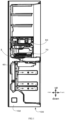
- FIG. 1 is a side view schematically showing a refrigerator 100 having a water supply device 2 according to an embodiment of the present invention.
- a shape of a refrigerator body 102 of the refrigerator 100 is schematically shown by a one-dot dash line.
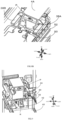
- FIGS. 2A and 2B are perspective views showing an arrangement inside the refrigerator of the water supply device 2 according to the embodiment of the present invention connected between a water tank 50 and an ice making tray 64, FIG. 2A is viewed from the left front side, and FIG. 2B is viewed from the left rear side.
- FIG. 3 is a perspective view showing an arrangement of the water supply device 2 according to the embodiment of the present invention, a water supply panel 60 and the ice making tray 64. In FIG. 3 , a state in which a rear surface of a housing 4 of the water supply device 2 is removed to make an interior visually recognizable is shown.
- FIG. 4 is a perspective view showing a shape of the water supply device 2 according to the embodiment of the present invention.
- a vegetable container 70 is disposed at a substantially central position in a height direction of the refrigerator body 102, and the water tank 50 is provided on a shelf 40.
- the water supply panel 60 is provided below the vegetable container 70, and the ice making tray 64 is provided below the water supply panel.
- the ice making tray 64 is mounted on a rotation shaft of a driving portion 66. By rotation of the rotation shaft of the driving portion 66, the ice making tray 64 is rotatable between an ice making position where an opening surface of the ice making tray 64 faces upwards and an ice releasing position where the opening surface faces downwards. In the ice releasing position, generated ice falls from the ice making tray 64 into an ice container disposed below.
- the shelf 40, the water supply panel 60 and the driving portion 66 are fixed in the refrigerator body 102.
- the water supply device 2 is disposed on a rear side of the refrigerator body 102, and supplies liquid (for example, drinking water) in the water tank 50 disposed above to the ice making tray 64 disposed below.
- the water supply device 2 includes a housing 4, and a pipeline 10 forming a flow path and a pump 12 for allowing the liquid in the flow path to flow are disposed inside the housing 4 (see FIG. 3 ).
- a liquid inlet P serving as a flow path inlet and a liquid outlet Q serving as a flow path outlet are formed in the housing 4 (see FIG. 4 ).
- a connection portion 52 of the water tank 50 is inserted into the liquid inlet P (see FIG. 8B ).
- the liquid outlet Q is disposed below a recess 62 of the water supply panel 60, that is, at a liquid supply position above the opening surface of the ice making tray 64 at the ice making position.
- the water supply device 2 is mounted to the shelf 40 located above and the water supply panel 60 located below.
- An input side positioning and fixing portion R is formed in the housing 4 and mainly formed by an input side insertion portion 30 and an input side guide portion 32.
- the housing 4 is mounted to the shelf 40 by the input side positioning and fixing portion R.
- the liquid inlet P can be positioned with respect to the connection portion 52 of the water tank 50 and the housing 4 can be fixed to the shelf 40.
- an output side positioning and fixing portion S is formed in the housing 4 and mainly formed by an output side insertion portion 20.
- the housing 4 is mounted to the water supply panel 60 by the output side positioning and fixing portion S.
- the liquid outlet Q can be positioned with respect to a position of water supply to the ice making tray 64 and the housing 4 can be fixed to the water supply panel 60.
- the housing 4 includes an input side housing 4A, an output side housing 4C and a buffer housing 4B, the input side housing 4A includes the input side positioning and fixing portion R for positioning, the output side housing 4C includes the output side positioning and fixing portion S, and the buffer housing 4B connects the input side housing 4A and the output side housing 4C and absorbs a deviation of relative positions of the input side housing 4A and the output side housing 4C.
- the input side housing 4A is fixed in position by the input side positioning and fixing portion R
- the output side housing 4C is fixed in position by the output side positioning and fixing portion S.
- the buffer housing 4B has an effect of connecting the input side housing 4A and the output side housing 4C and absorbing the slight deviation of the relative positions of the input side housing 4A and the output side housing 4C.
- the input side housing 4A, the buffer housing 4B and the output side housing 4C are integrally formed from a resin material having elasticity.
- the input side housing 4A, the buffer housing 4B and the output side housing 4C may be formed from the same resin material, or may be formed from different resin materials using two-color forming, or the like.
- only the buffer housing 4B may be formed of a more elastic soft material.
- the liquid in the water tank 50 is sucked in from the liquid inlet P, flows downwards in the pipeline 10, and reaches the liquid outlet Q disposed at the water supply position below the water supply panel 60.
- the liquid flows down from the liquid outlet Q and is supplied to the ice making tray 64 at the ice making position.
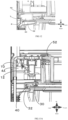
- FIG. 5A is a perspective view showing the output side housing 4C, particularly, a periphery of the liquid outlet Q of the water supply device 2 according to the embodiment of the present invention.
- FIG. 5B is a side sectional view showing section A-A of FIG. 5A .
- FIG. 6A is a side sectional view showing the output side housing 4C and members around the output side housing of the water supply device 2 according to the embodiment of the present invention.
- FIG. 6B is an enlarged side sectional view showing a periphery of the output side positioning and fixing portion S of FIG. 6A , showing a state immediately before the output side insertion portion 20 of the output side housing 4C is fitted into the recess 62 of the water supply panel 60.
- FIG. 6C is a side sectional view showing a state in which the output side insertion portion 20 of the output side housing 4C is moved downwards from the state of FIG. 6B and fitted into the recess 62 of the water supply panel 60.
- a fixing member 24 is mounted, and the fixing member 24 covers a body portion 4C1 of the output side housing 4C provided with the pipeline 10.
- a fixing surface 24A at a lower end of the fixing member 24 can hold the pipeline 10 protruding from an opening at the lower end of the fixing member 24 by a prescribed length.
- the truncated-cone-shaped output side insertion portion 20 is formed in a region below the fixing member 24, and an outer diameter of the truncated-cone-shaped output side insertion portion 20 becomes smaller towards a front end.
- the pipeline 10 is fixed in a state of protruding from the opening by the predetermined length, and the opening is provided in a surface of the front end of the truncated cone, i.e., a lower surface of the output side insertion portion 20.
- positions of an output side end portion having the liquid outlet Q of the flow path and the output side insertion portion 20 having the output side positioning and fixing portion S are determined by each other.
- a region around the pipeline 10 in the output side housing 4C is covered with a heat insulating material.
- a flat-plate-shaped sealing member 22 having elasticity is mounted on the lower surface of the output side insertion portion 20.
- the sealing member 22 has an opening for the pipeline 10 to pass through in a central portion of the planar shape.
- the water supply panel 60 is provided above the ice making tray 64 and fixed to the refrigerator body 102.
- the water supply panel 60 has the recess 62, and the recess 62 is provided right above the ice making tray.
- the recess 62 forms a region corresponding to the output side positioning and fixing portion S.
- a position of the recess 62 is determined with respect to the water supply position for supplying the liquid to the ice making tray 64, and the recess 62 has a tapered inner surface corresponding to a shape of the output side insertion portion 20 on the truncated cone. That is, the recess 62 has the tapered inner surface, and an inner diameter of the tapered inner surface becomes narrower towards a bottom surface.
- the recess 62 has the bottom surface, and an opening 62A is formed in the bottom surface.
- the output side insertion portion 20 is further pressed into the bottom surface side of the recess 62, and the sealing member 22 is fixed in a slightly compressive deformation state.
- a front end portion of the pipeline 10 having the liquid outlet Q is positioned in front-rear, left-right and up-down directions with respect to the water supply position for supplying the liquid to the ice making tray 64.
- the flat-plate-shaped sealing member 22 is disposed on the lower surface of the output side insertion portion 20, when the output side insertion portion 20 is inserted into the recess 62, an insertion resistance is not generated compared with a case where the sealing member is wound around a side surface of the output side insertion portion 20. Therefore, the output side insertion portion 20 does not get caught and stop halfway in the recess 62. Furthermore, since the flat-plate-shaped sealing member 22 abuts against the bottom surface (which is a plane) of the recess 62 and is slightly compressed for sealing, a position in an insertion direction can be defined, and a stable sealing function can be obtained.
- the liquid outlet Q is positioned with respect to the water supply position S by inserting the output side insertion portion 20 into the recess 62, the position of the recess 62 is determined with respect to the water supply position, and the recess 62 has the tapered inner surface corresponding to the shape of the truncated-cone-shaped output side insertion portion 20.
- FIG. 7 is a perspective view showing the water tank 50, the vegetable container 70 and the ice making tray 64 after the water supply device 2 is removed.
- FIG. 8A is a view showing a state immediately before the connection portion 52 of the water tank 50 is connected to the liquid inlet P of the input side housing 4A of the water supply device 2.
- FIG. 8B is an enlarged perspective view of a periphery of the liquid inlet P of the input side housing 4A in FIG. 8A .
- the shelf 40 on which the water tank 50 is placed is fixed to the refrigerator body 102, the tapered guide groove 42, or the like, is formed behind the water tank 50, and the tapered guide groove 42 is configured to mount the input side housing 4A of the water supply device 2.
- the connection portion 52 of the water tank 50 is required to be connected to the liquid inlet P provided in the input side housing 4A. Therefore, the liquid inlet P is required to be positioned with respect to a position of connection with the water tank 50, and the input side housing 4A is fixed to the shelf 40.
- a tank guide 38B is provided on the input side housing 4A side, and the tank guide 38B guides an outer surface of the water tank 50. Furthermore, in order to maintain the state in which the connection portion 52 of the water tank 50 is connected to the liquid inlet P, a tank engagement portion 38A is provided on the input side housing 4A side, and the tank engagement portion 38A is engaged with the water tank 50.
- FIG. 9 is a perspective view showing a periphery of the input side positioning and fixing portion R of the water supply device 2 according to the embodiment of the present invention.
- FIG. 10 is a perspective view showing a region of the shelf 40 corresponding to the input side insertion portion 30.
- FIG. 11 is a plan sectional view showing section B-B of FIG. 10 .
- the input side insertion portion 30 is formed, and the input side insertion portion 30 has a tapered outer surface with a width reduced towards the front end.
- the input side insertion portion 30 forms a part of the input side positioning and fixing portion R.
- the tapered guide groove 42 is formed on the shelf 40 side, the position of the tapered guide groove 42 is determined with respect to the position of connection with the water tank 50, and a shape of the tapered guide groove 42 corresponds to a shape of the input side insertion portion 30.
- the tapered guide groove 42 forms a region corresponding to the input side positioning and fixing portion R.
- the liquid inlet P can be positioned in the front-rear and left-right directions with respect to the position of connection with the water tank 50.
- the input side insertion portion 30 is inserted into the tapered guide groove 42, the input side insertion portion 30 is provided in the input side housing 4A and tapered in a width direction, and the tapered guide groove 42 is provided in the shelf 40, such that guidance is performed using the tapered surface to perform positioning in the width direction, and positioning in a depth direction is performed by abutting the tapered surfaces against each other.
- the input side housing 4A can be easily and reliably positioned in the front-rear and left-right directions, and then, the liquid inlet P is positioned in the front-rear and left-right directions with respect to the position of connection with the water tank 50.
- FIG. 12 is a side sectional view showing section C-C of FIG. 11 .
- the input side guide portion 32 is formed at a position corresponding to a lower surface of the shelf 40 in the height direction of the input side housing 4A, and the shelf 40 is disposed in a space between the input side guide portion and an upper side surface where the input side insertion portion 30 is formed.
- the input side guide portion 32 and the upper side surface on which the input side insertion portion 30 is formed form a clamping portion T which clamps the shelf 40 from an upper side and a lower side.
- the clamping portion T forms a part of the input side positioning and fixing portion R
- the clamped shelf 40 forms the region corresponding to the input side positioning and fixing portion R.
- the shelf 40 has an arcuately expanded section shape, and the input side housing 4A is firmly fixed to the shelf 40 by slightly elastically deforming the input side guide portion 32.
- the input side positioning and fixing portion R has the clamping portion T which clamps the shelf 40 from the upper side and the lower side, and by the clamping portion T clamping the shelf 40 from the upper side and the lower side, the input side housing 4Ais positioned in the up-down direction, and fixed to the shelf 40.
- the input side housing 4A can be easily and reliably positioned in the up-down direction, and then, the liquid inlet P is positioned in the up-down direction with respect to the position of connection with the water tank 50.
- FIG. 13A is a side sectional view showing section D-D of FIG. 10 .
- FIG. 13B is an enlarged side sectional view showing a concave-convex fitting structure 32A, 44 of FIG. 13A .
- FIG. 14A is a side sectional view showing section E-E of FIG. 10 .
- FIG. 14B is an enlarged side sectional view showing a concave-convex fitting structure 34, 46 of FIG. 14A .
- a groove portion 32A and a protruding portion 44 are fitted to form the concave-convex fitting structure 32A, 44, the groove portion 32A is formed in the input side guide portion 32 of the input side housing 4A, and the protruding portion 44 is formed in the shelf 40.
- a position of the input side housing 4A in the front-rear direction is kept reliably.
- a concave-convex portion 34 is fitted with a concave-convex portion 46 to form the concave-convex fitting structure 34, 46, the concave-convex portion 34 is formed in the input side housing 4A, and the concave-convex portion 46 is formed in the shelf 40.
- the input side housing 4A is pressed by the shelf 40 and does not lift upwards.
- a convex portion 36 is fitted with a groove portion 48, the convex portion 36 is formed outside the concave-convex portion 34 of the input side housing 4A, and the groove portion 48 is formed in the shelf 40. Since a fitting direction of the concave-convex portion 34 formed in the input side housing 4A is opposite to a fitting direction of the convex portions 36 on both sides, the shelf 40 can be clamped and fixed.
- FIG. 15A is a perspective view showing the shape of the water supply device 2 according to the embodiment of the present invention.
- FIG. 15B is an enlarged perspective view showing a region of the buffer housing 4B of FIG. 15A .
- the buffer housing 4B has a corrugated structure, and the buffer housing 4B connects the input side housing 4A and the output side housing 4C.
- the corrugated structure has such a strength that the corrugated structure is not deformed by own weight in a state in which all members, such as the pipeline 10, the pump 12, electric system components related to the pump 12, or the like, are mounted. Therefore, the buffer housing can be easily mounted to a predetermined position within the refrigerator 100 in a state of the integrated housing 4.
- the corrugated structure can be deformed to absorb the deviation.
- the water supply device 2 can be easily mounted to a predetermined place in the refrigerator 100, and the deviation of the relative positions of the input side housing 4A and the output side housing 4C can be appropriately absorbed.
- the water supply device 2 can be easily mounted to the refrigerator 100 in a short time only by mounting the integrated housing 4 to the upper shelf 40 and the lower water supply panel 60 and connecting a connector of wiring of a motor for driving the pump 12 to a connector on the refrigerator body 102 side.
- positioning can be easily performed in a short time.
- the input side positioning and fixing portion R and the output side positioning and fixing portion S in the present invention are not limited to the above-mentioned embodiments. Any other input side positioning and fixing mechanism may be adopted in any mechanism capable of fixing the input side housing 4A in the state where the liquid inlet P is positioned with respect to the position of connection with the water tank 50. Similarly, any other output side positioning and fixing mechanism may be adopted in any mechanism capable of fixing the output side housing 4C in the state where the liquid outlet Q is positioned with respect to the position of water supply to the ice making tray 64.
- the buffer housing 4B is not limited to the corrugated structure.
- the buffer housing 4B may be formed of a soft material having higher elasticity than the input side housing 4A and the output side housing 4C, and any other buffer mechanism may be adopted.
- the water supply device 2 is disposed in the refrigerator 100 having the water tank 50, and supplies the liquid in the water tank 50 to the ice making tray 64
- the water supply device 2 includes the housing 4, the housing 4 is provided therein with the flow path 10 and the pump 12 for allowing the liquid to flow, and includes the liquid inlet P forming the inlet of the flow path 10 and the liquid outlet Q forming the outlet of the flow path 10, and the housing 4 includes: the input side housing 4A having the input side positioning and fixing portion R for positioning and fixing the liquid inlet P with respect to the position of connection with the water tank 50; the output side housing 4C having the output side positioning and fixing portion S for positioning and fixing the liquid outlet Q with respect to the position of water supply to the ice making tray 64; and the buffer housing 4B connected between the input side housing 4A and the output side housing 4C and absorbing the deviation of the relative positions of the input side housing 4A and the output side housing 4C.
- the water supply device 2 can be mounted in the refrigerator 100 as long as the integrated housing 4 in which the flow path 10 and the pump 12 are disposed is provided. Meanwhile, the liquid inlet P can be positioned with respect to the water tank 50 by the input side positioning and fixing portion R, the liquid outlet Q can be positioned with respect to the ice making tray 64 by the output side positioning and fixing portion S, and the deviation of the relative positions of the input side housing 4A and the output side housing 4C can be absorbed by the buffer housing 4B.
- the water supply device 2 can be provided, which can be easily mounted in the refrigerator 100 in the short work time and can realize reliable positioning of the liquid inlet P and the liquid outlet Q.
Landscapes
- Engineering & Computer Science (AREA)
- Physics & Mathematics (AREA)
- Mechanical Engineering (AREA)
- Thermal Sciences (AREA)
- General Engineering & Computer Science (AREA)
- Devices That Are Associated With Refrigeration Equipment (AREA)
- Devices For Dispensing Beverages (AREA)
Abstract
Description
- The present invention relates to a water supply device and a refrigerator, and the water supply device is disposed in the refrigerator and supplies liquid in a water tank to an ice making tray.
- There is known a refrigerator having a water supply device which sucks water in a water tank by a pump and supplies the water to an ice making tray through a water supply pipe. there is provided a refrigerator in which an inlet on an input side of the water supply pipe is positioned with respect to the water tank, an outlet on an output side of the water supply pipe is positioned with respect to the ice making tray, and a positional deviation of the water supply pipe on the input side and the output side is absorbed by a connection pipe (see, for example, patent document 1:
Japanese Publication No. 2011-52933 - However, in the refrigerator described in patent document 1, each of the input side of the water supply pipe, the pump, the connection pipe and the output side of the water supply pipe is required to be connected, and the members are mounted at predetermined positions in the refrigerator while the inlet on the input side of the water supply pipe and the outlet on the output side of the water supply pipe are positioned. Therefore, the water supply device cannot be easily provided in the refrigerator, and a long work time is required.
- Therefore, an object of the present invention is to solve the above-mentioned problem and provide a water supply device which is provided in a refrigerator for supplying liquid in a water tank to an ice making tray, can be easily mounted in the refrigerator in a short work time, and can realize reliable positioning of an inlet and an outlet of a flow path.
- The water supply device according to the present invention is provided in the refrigerator with the water tank, and supplies the liquid in the water tank to the ice making tray,
- the water supply device includes a housing, a flow path and a pump for allowing the liquid to flow are arranged in the housing, and the housing includes a liquid inlet forming an inlet of the flow path and a liquid outlet forming an outlet of the flow path,
- the housing includes:
- an input side housing including an input side positioning and fixing portion, the input side positioning and fixing portion being configured to position and fix the liquid inlet with respect to a position of connection with the water tank;
- an output side housing including an output side positioning and fixing portion, the output side positioning and fixing portion being configured to position and fix the liquid outlet with respect to a position of water supply to the ice making tray; and
- a buffer housing which connects the input side housing and the output side housing and absorbs a deviation of relative positions of the input side housing and the output side housing.
- According to the present invention, the water supply device can be mounted in the refrigerator only by providing the integrated housing provided therein with the flow path and the pump. In particular, the liquid inlet can be positioned with respect to the water tank by the input side positioning and fixing portion of the input side housing, the liquid outlet can be positioned with respect to the ice making tray by the output side positioning and fixing portion of the output side housing, and the deviation of the relative positions of the input side housing and the output side housing can be absorbed by the buffer housing. Thus, the liquid inlet and the liquid outlet can be reliably positioned.
- As described above, the present invention can provide the water supply device which can be easily mounted in the refrigerator in the short work time and can realize reliable positioning of the liquid inlet and the liquid outlet.
- Furthermore, in the water supply device according to the present invention, the buffer housing has a corrugated structure, the corrugated structure is not deformed by own weight in a state where all the members are mounted, and the corrugated housing is deformed when a load applied to the buffer housing is greater than the own weight.
- According to the present invention, the corrugated structure has such a strength that the corrugated structure is not deformed by the own weight in the state where all the members are mounted, and therefore, the corrugated structure can be easily mounted to a predetermined place in the refrigerator in a state of the integrated housing. Meanwhile, even when the input side housing and the output side housing are positioned separately to cause the deviation of the relative positions, the corrugated structure can be deformed to absorb the deviation. That is, the water supply device can be easily mounted at a predetermined position within the refrigerator, and the deviation of the relative positions of the input side housing and the output side housing can be appropriately absorbed.
- Furthermore, in the water supply device according to the present invention,
- the output side positioning and fixing portion is formed by a truncated-cone-shaped output side insertion portion, a position of the truncated-cone-shaped output side insertion portion is determined with respect to an output side end portion of the flow path serving as the liquid outlet, and an outer diameter of the truncated cone shape is reduced towards a front end,
- the output side insertion portion is inserted into a recess to position the liquid outlet with respect to the water supply position, a position of the recess is determined with respect to the water supply position, and the recess has a tapered inner surface corresponding to the output side insertion portion in shape.
- According to the present invention, the truncated-cone-shaped output side insertion portion provided in the output side housing is inserted into the recess having the tapered inner surface corresponding to the output side insertion portion, such that guidance can be performed using the tapered surface, and the liquid outlet can be easily and reliably positioned in front-rear, left-right, and up-down directions with respect to the water supply position.
- Furthermore, in the water supply device according to the present invention,
- the input side positioning and fixing portion has an input side insertion portion, the input side insertion portion has a tapered outer surface, and a width of the tapered outer surface is reduced towards a front end,
- the input side insertion portion is inserted into a tapered guide groove to position the liquid inlet in front-rear and left-right directions with respect to the connection position, the tapered guide groove is provided in a shelf, a position of the tapered guide groove is determined with respect to the connection position, and a shape of the tapered guide groove corresponds to a shape of the input side insertion portion.
- According to the present invention, the input side insertion portion is inserted into the tapered guide groove, the input side insertion portion is provided in the input side housing and tapered in a width direction, and the tapered guide groove is provided in the shelf, such that guidance is performed using the tapered surface to perform positioning in the width direction, and positioning in a depth direction is performed by abutting the tapered surfaces against each other. Thus, the input side housing can be easily and reliably positioned in the front-rear and left-right directions, thus further positioning the liquid inlet with respect to the position of connection with the water tank.
- Furthermore, in the water supply device according to the present invention,
- the input side positioning and fixing portion has a clamping portion, and the clamping portion clamps the shelf from an upper side and a lower side,
- the clamping portion clamps the shelf from the upper side and the lower side to position the liquid inlet in the up-down direction with respect to the connection position.
- According to the present invention, the shelf is clamped from the upper side and the lower side by the clamping portion provided in the input side housing, thus easily and reliably positioning the liquid inlet in the up-down direction.
- As described above, the present invention can provide the water supply device which is provided in the refrigerator to supply the liquid in the water tank to the ice making tray, can be easily mounted in the refrigerator in the short work time, and can realize reliable positioning of the inlet and the outlet of the flow path.
-
-
FIG. 1 is a side view schematically showing a refrigerator having a water supply device according to an embodiment of the present invention. -
FIG. 2A is a perspective view showing an arrangement inside the refrigerator of the water supply device according to the embodiment of the present invention connected between a water tank and an ice making tray, as viewed from the left front side. -
FIG. 2B is a perspective view showing the arrangement inside the refrigerator of the water supply device according to the embodiment of the present invention connected between the water tank and the ice making tray, as viewed from the left rear side. -
FIG. 3 is a perspective view showing an arrangement of the water supply device according to the embodiment of the present invention, a water supply panel and the ice making tray. -
FIG. 4 is a perspective view showing a shape of the water supply device according to the embodiment of the present invention. -
FIG. 5A is a perspective view showing an output side housing, particularly, a periphery of a liquid outlet of the water supply device according to the embodiment of the present invention. -
FIG. 5B is a side sectional view showing section A-A ofFIG. 5A . -
FIG. 6A is a side sectional view showing the output side housing and members around the output side housing of the water supply device according to the embodiment of the present invention. -
FIG. 6B is an enlarged side sectional view showing a periphery of an output side positioning and fixing portion ofFIG. 6A , showing a state immediately before an output side insertion portion of the output side housing is fitted into a recess of the water supply panel. -
FIG. 6C is a side sectional view showing a state in which the output side insertion portion of the output side housing is moved downwards from the state ofFIG. 6B and fitted into the recess of the water supply panel. -
FIG. 7 is a perspective view showing an arrangement of the water tank, a vegetable container, the water supply panel and the ice making tray after the water supply device is removed. -
FIG. 8A is a view showing a state immediately before a connection portion of the water tank is connected to a liquid inlet of an input side housing of the water supply device. -
FIG. 8B is an enlarged perspective view of a periphery of the liquid inlet of the input side housing inFIG. 8A . -
FIG. 9 is a perspective view showing a periphery of an input side positioning and fixing portion of the water supply device according to the embodiment of the present invention. -
FIG. 10 is a perspective view showing a region of a shelf corresponding to an input side insertion portion. -
FIG. 11 is a plan sectional view showing section B-B ofFIG. 10 . -
FIG. 12 is a side sectional view showing section C-C ofFIG. 11 . -
FIG. 13A is a side sectional view showing section D-D ofFIG. 10 . -
FIG. 13B is an enlarged side sectional view showing a concave-convex fitting structure ofFIG. 13A . -
FIG. 14A is a side sectional view showing section E-E ofFIG. 10 . -
FIG. 14B is an enlarged side sectional view showing a concave-convex fitting structure ofFIG. 14A . -
FIG. 15A is a perspective view showing the shape of the water supply device according to the embodiment of the present invention. -
FIG. 15B is an enlarged perspective view showing a region of a buffer housing ofFIG. 15A . - Embodiments for implementing the present invention are described below with reference to accompanying drawings. Furthermore, a water supply device and a refrigerator described below are used to embody the technical idea of the present invention, and the invention will not be limited to the following content as long as there is no specific description.
- In the drawings, members with the same functions are sometimes marked with the same symbols. In order to clarify the description, the sizes, positional relationships, or the like, of the members shown in each drawing are sometimes shown in an exaggerated manner. In the present specification, the refrigerator is placed on a horizontal floor, a door side is set as a front side, and an opposite side is set as a rear side. Up-down, front-rear and left-right directions are shown by arrows in the drawings.
-
FIG. 1 is a side view schematically showing arefrigerator 100 having awater supply device 2 according to an embodiment of the present invention. A shape of arefrigerator body 102 of therefrigerator 100 is schematically shown by a one-dot dash line.FIGS. 2A and 2B are perspective views showing an arrangement inside the refrigerator of thewater supply device 2 according to the embodiment of the present invention connected between awater tank 50 and anice making tray 64,FIG. 2A is viewed from the left front side, andFIG. 2B is viewed from the left rear side.FIG. 3 is a perspective view showing an arrangement of thewater supply device 2 according to the embodiment of the present invention, awater supply panel 60 and theice making tray 64. InFIG. 3 , a state in which a rear surface of a housing 4 of thewater supply device 2 is removed to make an interior visually recognizable is shown.FIG. 4 is a perspective view showing a shape of thewater supply device 2 according to the embodiment of the present invention. - In the
refrigerator 100 shown inFIG. 1 , avegetable container 70 is disposed at a substantially central position in a height direction of therefrigerator body 102, and thewater tank 50 is provided on ashelf 40. Thewater supply panel 60 is provided below thevegetable container 70, and theice making tray 64 is provided below the water supply panel. Theice making tray 64 is mounted on a rotation shaft of a drivingportion 66. By rotation of the rotation shaft of the drivingportion 66, theice making tray 64 is rotatable between an ice making position where an opening surface of theice making tray 64 faces upwards and an ice releasing position where the opening surface faces downwards. In the ice releasing position, generated ice falls from theice making tray 64 into an ice container disposed below. Theshelf 40, thewater supply panel 60 and the drivingportion 66 are fixed in therefrigerator body 102. - The
water supply device 2 is disposed on a rear side of therefrigerator body 102, and supplies liquid (for example, drinking water) in thewater tank 50 disposed above to theice making tray 64 disposed below. Thewater supply device 2 includes a housing 4, and apipeline 10 forming a flow path and apump 12 for allowing the liquid in the flow path to flow are disposed inside the housing 4 (seeFIG. 3 ). A liquid inlet P serving as a flow path inlet and a liquid outlet Q serving as a flow path outlet are formed in the housing 4 (seeFIG. 4 ). As described later, aconnection portion 52 of thewater tank 50 is inserted into the liquid inlet P (seeFIG. 8B ). The liquid outlet Q is disposed below arecess 62 of thewater supply panel 60, that is, at a liquid supply position above the opening surface of theice making tray 64 at the ice making position. - The
water supply device 2 is mounted to theshelf 40 located above and thewater supply panel 60 located below. An input side positioning and fixing portion R is formed in the housing 4 and mainly formed by an inputside insertion portion 30 and an inputside guide portion 32. The housing 4 is mounted to theshelf 40 by the input side positioning and fixing portion R. In thewater supply device 2, by the input side positioning and fixing portion R formed in the housing 4 and a corresponding part (atapered guide groove 42, or the like, described later) provided in theshelf 40, the liquid inlet P can be positioned with respect to theconnection portion 52 of thewater tank 50 and the housing 4 can be fixed to theshelf 40. - Furthermore, an output side positioning and fixing portion S is formed in the housing 4 and mainly formed by an output
side insertion portion 20. The housing 4 is mounted to thewater supply panel 60 by the output side positioning and fixing portion S. In thewater supply device 2, by the output side positioning and fixing portion S formed in the housing 4 and a corresponding part (therecess 62 described later) provided in thewater supply panel 60, the liquid outlet Q can be positioned with respect to a position of water supply to theice making tray 64 and the housing 4 can be fixed to thewater supply panel 60. - The housing 4 includes an
input side housing 4A, anoutput side housing 4C and abuffer housing 4B, theinput side housing 4A includes the input side positioning and fixing portion R for positioning, theoutput side housing 4C includes the output side positioning and fixing portion S, and thebuffer housing 4B connects theinput side housing 4A and theoutput side housing 4C and absorbs a deviation of relative positions of theinput side housing 4A and theoutput side housing 4C. Theinput side housing 4A is fixed in position by the input side positioning and fixing portion R, and theoutput side housing 4C is fixed in position by the output side positioning and fixing portion S. In this case, the positions of theinput side housing 4A and theoutput side housing 4C sometimes have a slight deviation. Therefore, thebuffer housing 4B has an effect of connecting theinput side housing 4A and theoutput side housing 4C and absorbing the slight deviation of the relative positions of theinput side housing 4A and theoutput side housing 4C. - The
input side housing 4A, thebuffer housing 4B and theoutput side housing 4C are integrally formed from a resin material having elasticity. Theinput side housing 4A, thebuffer housing 4B and theoutput side housing 4C may be formed from the same resin material, or may be formed from different resin materials using two-color forming, or the like. For example, only thebuffer housing 4B may be formed of a more elastic soft material. - With the
water supply device 2 having the above structure, when thepump 12 is driven, the liquid in thewater tank 50 is sucked in from the liquid inlet P, flows downwards in thepipeline 10, and reaches the liquid outlet Q disposed at the water supply position below thewater supply panel 60. The liquid flows down from the liquid outlet Q and is supplied to theice making tray 64 at the ice making position. -
FIG. 5A is a perspective view showing theoutput side housing 4C, particularly, a periphery of the liquid outlet Q of thewater supply device 2 according to the embodiment of the present invention.FIG. 5B is a side sectional view showing section A-A ofFIG. 5A .FIG. 6A is a side sectional view showing theoutput side housing 4C and members around the output side housing of thewater supply device 2 according to the embodiment of the present invention.FIG. 6B is an enlarged side sectional view showing a periphery of the output side positioning and fixing portion S ofFIG. 6A , showing a state immediately before the outputside insertion portion 20 of theoutput side housing 4C is fitted into therecess 62 of thewater supply panel 60.FIG. 6C is a side sectional view showing a state in which the outputside insertion portion 20 of theoutput side housing 4C is moved downwards from the state ofFIG. 6B and fitted into therecess 62 of thewater supply panel 60. - In the present embodiment, a fixing
member 24 is mounted, and the fixingmember 24 covers a body portion 4C1 of theoutput side housing 4C provided with thepipeline 10. A fixingsurface 24A at a lower end of the fixingmember 24 can hold thepipeline 10 protruding from an opening at the lower end of the fixingmember 24 by a prescribed length. The truncated-cone-shaped outputside insertion portion 20 is formed in a region below the fixingmember 24, and an outer diameter of the truncated-cone-shaped outputside insertion portion 20 becomes smaller towards a front end. That is, thepipeline 10 is fixed in a state of protruding from the opening by the predetermined length, and the opening is provided in a surface of the front end of the truncated cone, i.e., a lower surface of the outputside insertion portion 20. - Thus, positions of an output side end portion having the liquid outlet Q of the flow path and the output
side insertion portion 20 having the output side positioning and fixing portion S are determined by each other. In order to prevent the liquid flowing in thepipeline 10 from freezing, preferably, a region around thepipeline 10 in theoutput side housing 4C is covered with a heat insulating material. Furthermore, a flat-plate-shaped sealingmember 22 having elasticity is mounted on the lower surface of the outputside insertion portion 20. The sealingmember 22 has an opening for thepipeline 10 to pass through in a central portion of the planar shape. - The
water supply panel 60 is provided above theice making tray 64 and fixed to therefrigerator body 102. Thewater supply panel 60 has therecess 62, and therecess 62 is provided right above the ice making tray. In the present embodiment, therecess 62 forms a region corresponding to the output side positioning and fixing portion S. A position of therecess 62 is determined with respect to the water supply position for supplying the liquid to theice making tray 64, and therecess 62 has a tapered inner surface corresponding to a shape of the outputside insertion portion 20 on the truncated cone. That is, therecess 62 has the tapered inner surface, and an inner diameter of the tapered inner surface becomes narrower towards a bottom surface. Therecess 62 has the bottom surface, and anopening 62A is formed in the bottom surface. - As shown in
FIGS. 6B and 6C , when the truncated-cone-shaped outputside insertion portion 20 is inserted into therecess 62, thepipeline 10 protruding from the outputside insertion portion 20 passes through theopening 62A provided in the bottom surface of therecess 62. Furthermore, when the outputside insertion portion 20 is pressed into therecess 62, the sealingmember 22 mounted on the lower surface of the outputside insertion portion 20 abuts against the bottom surface of therecess 62. At a position where theinput side housing 4A is fixed to the shelf 40 (described later), the outputside insertion portion 20 is further pressed into the bottom surface side of therecess 62, and the sealingmember 22 is fixed in a slightly compressive deformation state. Thus, a front end portion of thepipeline 10 having the liquid outlet Q is positioned in front-rear, left-right and up-down directions with respect to the water supply position for supplying the liquid to theice making tray 64. - As described above, since the flat-plate-shaped sealing
member 22 is disposed on the lower surface of the outputside insertion portion 20, when the outputside insertion portion 20 is inserted into therecess 62, an insertion resistance is not generated compared with a case where the sealing member is wound around a side surface of the outputside insertion portion 20. Therefore, the outputside insertion portion 20 does not get caught and stop halfway in therecess 62. Furthermore, since the flat-plate-shaped sealingmember 22 abuts against the bottom surface (which is a plane) of therecess 62 and is slightly compressed for sealing, a position in an insertion direction can be defined, and a stable sealing function can be obtained. - As described above, in the
water supply device 2, the liquid outlet Q is positioned with respect to the water supply position S by inserting the outputside insertion portion 20 into therecess 62, the position of therecess 62 is determined with respect to the water supply position, and therecess 62 has the tapered inner surface corresponding to the shape of the truncated-cone-shaped outputside insertion portion 20. By inserting the outputside insertion portion 20 into therecess 62, guidance can be performed using the tapered surface, and the liquid outlet Q is easily and reliably positioned in the front-rear, left-right and up-down directions with respect to the water supply position S. -
FIG. 7 is a perspective view showing thewater tank 50, thevegetable container 70 and theice making tray 64 after thewater supply device 2 is removed.FIG. 8A is a view showing a state immediately before theconnection portion 52 of thewater tank 50 is connected to the liquid inlet P of theinput side housing 4A of thewater supply device 2.FIG. 8B is an enlarged perspective view of a periphery of the liquid inlet P of theinput side housing 4A inFIG. 8A . - As shown in
FIG. 7 , theshelf 40 on which thewater tank 50 is placed is fixed to therefrigerator body 102, the taperedguide groove 42, or the like, is formed behind thewater tank 50, and the taperedguide groove 42 is configured to mount theinput side housing 4A of thewater supply device 2. As shown inFIGS. 8A and8B , theconnection portion 52 of thewater tank 50 is required to be connected to the liquid inlet P provided in theinput side housing 4A. Therefore, the liquid inlet P is required to be positioned with respect to a position of connection with thewater tank 50, and theinput side housing 4A is fixed to theshelf 40. - In order to easily connect the
connection portion 52 of thewater tank 50 to the liquid inlet P when thewater tank 50 is pressed rearwards, atank guide 38B is provided on theinput side housing 4A side, and thetank guide 38B guides an outer surface of thewater tank 50. Furthermore, in order to maintain the state in which theconnection portion 52 of thewater tank 50 is connected to the liquid inlet P, atank engagement portion 38A is provided on theinput side housing 4A side, and thetank engagement portion 38A is engaged with thewater tank 50. -
FIG. 9 is a perspective view showing a periphery of the input side positioning and fixing portion R of thewater supply device 2 according to the embodiment of the present invention.FIG. 10 is a perspective view showing a region of theshelf 40 corresponding to the inputside insertion portion 30.FIG. 11 is a plan sectional view showing section B-B ofFIG. 10 . - As shown in
FIG. 4 , at a position corresponding to an upper surface of theshelf 40 in a height direction of theinput side housing 4A, the inputside insertion portion 30 is formed, and the inputside insertion portion 30 has a tapered outer surface with a width reduced towards the front end. In the present embodiment, the inputside insertion portion 30 forms a part of the input side positioning and fixing portion R. - On the other hand, the tapered
guide groove 42 is formed on theshelf 40 side, the position of the taperedguide groove 42 is determined with respect to the position of connection with thewater tank 50, and a shape of the taperedguide groove 42 corresponds to a shape of the inputside insertion portion 30. In the present embodiment, the taperedguide groove 42 forms a region corresponding to the input side positioning and fixing portion R. - When the
input side housing 4A of thewater supply device 2 is mounted to theshelf 40, by inserting the inputside insertion portion 30 into the taperedguide groove 42 formed in theshelf 40, the liquid inlet P can be positioned in the front-rear and left-right directions with respect to the position of connection with thewater tank 50. - That is, the input
side insertion portion 30 is inserted into the taperedguide groove 42, the inputside insertion portion 30 is provided in theinput side housing 4A and tapered in a width direction, and the taperedguide groove 42 is provided in theshelf 40, such that guidance is performed using the tapered surface to perform positioning in the width direction, and positioning in a depth direction is performed by abutting the tapered surfaces against each other. Thus, in thewater supply device 2, theinput side housing 4A can be easily and reliably positioned in the front-rear and left-right directions, and then, the liquid inlet P is positioned in the front-rear and left-right directions with respect to the position of connection with thewater tank 50. -
FIG. 12 is a side sectional view showing section C-C ofFIG. 11 . As shown inFIG. 4 , the inputside guide portion 32 is formed at a position corresponding to a lower surface of theshelf 40 in the height direction of theinput side housing 4A, and theshelf 40 is disposed in a space between the input side guide portion and an upper side surface where the inputside insertion portion 30 is formed. Thus, as shown inFIG. 12 , the inputside guide portion 32 and the upper side surface on which the inputside insertion portion 30 is formed form a clamping portion T which clamps theshelf 40 from an upper side and a lower side. In the present embodiment, the clamping portion T forms a part of the input side positioning and fixing portion R, and the clampedshelf 40 forms the region corresponding to the input side positioning and fixing portion R. Theshelf 40 has an arcuately expanded section shape, and theinput side housing 4A is firmly fixed to theshelf 40 by slightly elastically deforming the inputside guide portion 32. - As described above, the input side positioning and fixing portion R has the clamping portion T which clamps the
shelf 40 from the upper side and the lower side, and by the clamping portion T clamping theshelf 40 from the upper side and the lower side, the input side housing 4Ais positioned in the up-down direction, and fixed to theshelf 40. Thus, in thewater supply device 2, theinput side housing 4A can be easily and reliably positioned in the up-down direction, and then, the liquid inlet P is positioned in the up-down direction with respect to the position of connection with thewater tank 50. -
FIG. 13A is a side sectional view showing section D-D ofFIG. 10 .FIG. 13B is an enlarged side sectional view showing a concave-convexfitting structure FIG. 13A .FIG. 14A is a side sectional view showing section E-E ofFIG. 10 .FIG. 14B is an enlarged side sectional view showing a concave-convexfitting structure FIG. 14A . - As shown in
FIG. 13B , agroove portion 32A and a protrudingportion 44 are fitted to form the concave-convexfitting structure groove portion 32A is formed in the inputside guide portion 32 of theinput side housing 4A, and the protrudingportion 44 is formed in theshelf 40. Thus, a position of theinput side housing 4A in the front-rear direction is kept reliably. - As shown in
FIG. 14B , a concave-convex portion 34 is fitted with a concave-convex portion 46 to form the concave-convexfitting structure convex portion 34 is formed in theinput side housing 4A, and the concave-convex portion 46 is formed in theshelf 40. Thus, theinput side housing 4A is pressed by theshelf 40 and does not lift upwards. Furthermore, aconvex portion 36 is fitted with agroove portion 48, theconvex portion 36 is formed outside the concave-convex portion 34 of theinput side housing 4A, and thegroove portion 48 is formed in theshelf 40. Since a fitting direction of the concave-convex portion 34 formed in theinput side housing 4A is opposite to a fitting direction of theconvex portions 36 on both sides, theshelf 40 can be clamped and fixed. - With such a fixing mechanism, even when the connecting
portion 52 of thewater tank 50 is mounted to and detached from the liquid inlet P of theinput side housing 4A, the position of theinput side housing 4A can be reliably held by applying a force to theinput side housing 4A. -
FIG. 15A is a perspective view showing the shape of thewater supply device 2 according to the embodiment of the present invention.FIG. 15B is an enlarged perspective view showing a region of thebuffer housing 4B ofFIG. 15A . In the present embodiment, thebuffer housing 4B has a corrugated structure, and thebuffer housing 4B connects theinput side housing 4A and theoutput side housing 4C. The corrugated structure has such a strength that the corrugated structure is not deformed by own weight in a state in which all members, such as thepipeline 10, thepump 12, electric system components related to thepump 12, or the like, are mounted. Therefore, the buffer housing can be easily mounted to a predetermined position within therefrigerator 100 in a state of the integrated housing 4. - On the other hand, when a load greater than the own weight is applied, corrugations are deformed. Thus, even when the
input side housing 4A and theoutput side housing 4B are positioned to generate the deviation of the relative positions, the corrugated structure can be deformed to absorb the deviation. With such a corrugated structure, thewater supply device 2 can be easily mounted to a predetermined place in therefrigerator 100, and the deviation of the relative positions of theinput side housing 4A and theoutput side housing 4C can be appropriately absorbed. - According to the above structure, the
water supply device 2 can be easily mounted to therefrigerator 100 in a short time only by mounting the integrated housing 4 to theupper shelf 40 and the lowerwater supply panel 60 and connecting a connector of wiring of a motor for driving thepump 12 to a connector on therefrigerator body 102 side. In particular, in the case of using the tapered surface, positioning can be easily performed in a short time. - However, the input side positioning and fixing portion R and the output side positioning and fixing portion S in the present invention are not limited to the above-mentioned embodiments. Any other input side positioning and fixing mechanism may be adopted in any mechanism capable of fixing the
input side housing 4A in the state where the liquid inlet P is positioned with respect to the position of connection with thewater tank 50. Similarly, any other output side positioning and fixing mechanism may be adopted in any mechanism capable of fixing theoutput side housing 4C in the state where the liquid outlet Q is positioned with respect to the position of water supply to theice making tray 64. - The
buffer housing 4B is not limited to the corrugated structure. For example, thebuffer housing 4B may be formed of a soft material having higher elasticity than theinput side housing 4A and theoutput side housing 4C, and any other buffer mechanism may be adopted. - As described above, the
water supply device 2 according to the present invention is disposed in therefrigerator 100 having thewater tank 50, and supplies the liquid in thewater tank 50 to theice making tray 64, thewater supply device 2 includes the housing 4, the housing 4 is provided therein with theflow path 10 and thepump 12 for allowing the liquid to flow, and includes the liquid inlet P forming the inlet of theflow path 10 and the liquid outlet Q forming the outlet of theflow path 10, and the housing 4 includes: theinput side housing 4A having the input side positioning and fixing portion R for positioning and fixing the liquid inlet P with respect to the position of connection with thewater tank 50; theoutput side housing 4C having the output side positioning and fixing portion S for positioning and fixing the liquid outlet Q with respect to the position of water supply to theice making tray 64; and thebuffer housing 4B connected between theinput side housing 4A and theoutput side housing 4C and absorbing the deviation of the relative positions of theinput side housing 4A and theoutput side housing 4C. - The
water supply device 2 can be mounted in therefrigerator 100 as long as the integrated housing 4 in which theflow path 10 and thepump 12 are disposed is provided. Meanwhile, the liquid inlet P can be positioned with respect to thewater tank 50 by the input side positioning and fixing portion R, the liquid outlet Q can be positioned with respect to theice making tray 64 by the output side positioning and fixing portion S, and the deviation of the relative positions of theinput side housing 4A and theoutput side housing 4C can be absorbed by thebuffer housing 4B. Thus, thewater supply device 2 can be provided, which can be easily mounted in therefrigerator 100 in the short work time and can realize reliable positioning of the liquid inlet P and the liquid outlet Q. - Although the embodiments and implementations of the present invention have been described, the disclosure can be changed in details of the structure, and combinations of elements, changes in the order, or the like, in the embodiments and implementations can be implemented without departing from the scope and spirit of the claimed invention.
-
-
FIGS. 1 ,5B to 6C and12 to 14B - : up

- : down

- : front

- : rear

-
-
FIGS. 2A to 5A ,7 to 10 and15A to 15B - : up
- : down
- : front
- : rear
- : left

- : right

-
-
FIG. 11 - : front
- : rear
- : left
- : right
-
Claims (10)
- A water supply device, provided in a refrigerator with a water tank for supplying liquid in the water tank to an ice making tray,wherein the water supply device comprises a housing, a flow path and a pump for allowing the liquid to flow are arranged in the housing, and the flow path has a liquid inlet and a liquid outlet,the housing comprises:an input side housing comprising an input side positioning and fixing portion, the input side positioning and fixing portion being configured to position and fix the liquid inlet with respect to a position of connection with the water tank;an output side housing comprising an output side positioning and fixing portion, the output side positioning and fixing portion being configured to position and fix the liquid outlet with respect to a position of water supply to the ice making tray; anda buffer housing which connects the input side housing and the output side housing and absorbs a deviation of relative positions of the input side housing and the output side housing.
- The water supply device according to claim 1, wherein the buffer housing has a corrugated structure, the corrugated structure is not deformed by own weight in a state where all the members are mounted, and the corrugated structure is deformed when a load greater than the own weight is applied to the buffer housing.
- The water supply device according to claim 1 or 2,wherein the output side positioning and fixing portion comprises a truncated-cone-shaped output side insertion portion, a position of the output side insertion portion is determined with respect to an output side end portion of the flow path with the liquid outlet, and an outer diameter of the output side insertion portion is reduced towards a front end,the output side insertion portion is inserted into a recess to position the liquid outlet with respect to the water supply position, a position of the recess is determined with respect to the water supply position, and the recess has a tapered inner surface corresponding to the output side insertion portion in shape.
- The water supply device according to claim 1 or 2,wherein the input side positioning and fixing portion has an input side insertion portion, the input side insertion portion has a tapered outer surface, and a width of the tapered outer surface is reduced towards a front end,the input side insertion portion is inserted into a tapered guide groove to position the liquid inlet in front-rear and left-right directions with respect to the connection position, the tapered guide groove is provided in a shelf, a position of the tapered guide groove is determined with respect to the connection position, and a shape of the tapered guide groove corresponds to a shape of the input side insertion portion.
- The water supply device according to claim 4,wherein the input side positioning and fixing portion has a clamping portion, and the clamping portion clamps the shelf from an upper side and a lower side,the clamping portion clamps the shelf from the upper side and the lower side to position the liquid inlet in the up-down direction with respect to the connection position.
- The water supply device according to claim 3, further comprising a fixing member, wherein the fixing member covers a body portion of the output side housing, a lower region of the fixing member forms the output side insertion portion, and the flow path passes through the fixing member.
- The water supply device according to claim 3, further comprising a water supply panel, wherein the water supply panel is provided above the ice making tray, the recess is provided on the water supply panel, and the recess is located right above the ice making tray.
- The water supply device according to claim 7, wherein a sealing member is mounted to a lower surface of the output side insertion portion, and the sealing member abuts against a bottom surface of the recess when the output side insertion portion is inserted into the recess.
- The water supply device according to claim 4, wherein the water tank comprises a connection portion connected with the liquid inlet, and the input side housing is provided with a tank guide for guiding the water tank and a tank engagement portion engaged with the water tank.
- A refrigerator, comprising a cabinet and a door for opening and closing the cabinet, wherein an ice making tray and a water tank for supplying water to the ice making tray are mounted in the cabinet, and the refrigerator further comprises the water supply device according to claim 1.
Applications Claiming Priority (2)
| Application Number | Priority Date | Filing Date | Title |
|---|---|---|---|
| JP2021057952A JP7558568B2 (en) | 2021-03-30 | 2021-03-30 | Fluid Supply Device |
| PCT/CN2022/083353 WO2022206669A1 (en) | 2021-03-30 | 2022-03-28 | Water supply device and refrigerator |
Publications (2)
| Publication Number | Publication Date |
|---|---|
| EP4300011A1 true EP4300011A1 (en) | 2024-01-03 |
| EP4300011A4 EP4300011A4 (en) | 2024-07-24 |
Family
ID=83455580
Family Applications (1)
| Application Number | Title | Priority Date | Filing Date |
|---|---|---|---|
| EP22778851.0A Pending EP4300011A4 (en) | 2021-03-30 | 2022-03-28 | WATER SUPPLY DEVICE AND REFRIGERATOR |
Country Status (4)
| Country | Link |
|---|---|
| EP (1) | EP4300011A4 (en) |
| JP (1) | JP7558568B2 (en) |
| CN (1) | CN117120791A (en) |
| WO (1) | WO2022206669A1 (en) |
Family Cites Families (19)
| Publication number | Priority date | Publication date | Assignee | Title |
|---|---|---|---|---|
| JPH0875332A (en) * | 1994-09-02 | 1996-03-19 | Toshiba Corp | Water supply device for automatic ice maker |
| JP4269548B2 (en) | 2001-08-21 | 2009-05-27 | 三菱電機株式会社 | refrigerator |
| JP4097596B2 (en) | 2003-12-18 | 2008-06-11 | 三洋電機株式会社 | Refrigerator with automatic ice machine |
| JP3807419B2 (en) * | 2004-07-27 | 2006-08-09 | 松下電器産業株式会社 | Refrigerator with ice making device |
| JP3807428B2 (en) | 2004-09-08 | 2006-08-09 | 松下電器産業株式会社 | Water supply device for ice making device and refrigerator |
| JP3783725B1 (en) | 2005-03-15 | 2006-06-07 | 松下電器産業株式会社 | refrigerator |
| JP4270323B1 (en) | 2008-03-17 | 2009-05-27 | パナソニック株式会社 | refrigerator |
| JP2011027371A (en) | 2009-07-29 | 2011-02-10 | Hitachi Appliances Inc | Refrigerator |
| JP5358359B2 (en) | 2009-09-04 | 2013-12-04 | 日立アプライアンス株式会社 | refrigerator |
| CN202393120U (en) * | 2011-11-22 | 2012-08-22 | 合肥美的荣事达电冰箱有限公司 | Ice machine and refrigerator |
| JP6061808B2 (en) * | 2013-08-07 | 2017-01-18 | 三菱電機株式会社 | refrigerator |
| CN203431358U (en) * | 2013-08-27 | 2014-02-12 | 王建序 | Water pipe fixedly connecting device |
| CN104344657B (en) * | 2014-03-07 | 2016-11-16 | 海尔集团公司 | Refrigerator |
| CN204717790U (en) * | 2015-04-08 | 2015-10-21 | 王金海 | A kind of oil-collecting formula energy-conserving and environment-protective smoke exhaust ventilator |
| KR102432001B1 (en) | 2015-10-14 | 2022-08-16 | 삼성전자주식회사 | Refrigerator |
| CN107990625A (en) * | 2017-10-13 | 2018-05-04 | 青岛海尔股份有限公司 | The installation method and method for dismounting of refrigerator and Icemaker assembly with Icemaker assembly |
| JP7018860B2 (en) | 2018-09-25 | 2022-02-14 | 日立グローバルライフソリューションズ株式会社 | Refrigerator and insulation divider |
| JP7249624B2 (en) * | 2018-12-26 | 2023-03-31 | アクア株式会社 | Refrigerator ice-making water supply unit, refrigerator, refrigerator assembly method |
| CN111795531B (en) * | 2019-04-09 | 2023-06-23 | 青岛海尔电冰箱有限公司 | refrigerator |
-
2021
- 2021-03-30 JP JP2021057952A patent/JP7558568B2/en active Active
-
2022
- 2022-03-28 CN CN202280025844.4A patent/CN117120791A/en active Pending
- 2022-03-28 EP EP22778851.0A patent/EP4300011A4/en active Pending
- 2022-03-28 WO PCT/CN2022/083353 patent/WO2022206669A1/en not_active Ceased
Also Published As
| Publication number | Publication date |
|---|---|
| WO2022206669A1 (en) | 2022-10-06 |
| JP7558568B2 (en) | 2024-10-01 |
| EP4300011A4 (en) | 2024-07-24 |
| JP2022154765A (en) | 2022-10-13 |
| CN117120791A (en) | 2023-11-24 |
Similar Documents
| Publication | Publication Date | Title |
|---|---|---|
| CN102361778B (en) | Electronic control device | |
| KR101485377B1 (en) | Temperature sensor supporting device and temperature sensor attachment structure | |
| EP2581946B1 (en) | Solar cell module terminal box | |
| EP3113335A1 (en) | Electric motor and method for manufacturing same | |
| EP4300011A1 (en) | Water supply device and refrigerator | |
| CN105818794A (en) | Coil assembly | |
| EP3660306A1 (en) | Integrated pump valve device for providing pressurized air | |
| US8895860B2 (en) | Grommet | |
| US8672383B2 (en) | Module load enabling bracket | |
| EP2000364A8 (en) | A dashboard assembly for a motor vehicle provided with a connector for connecting a portable electronic device | |
| EP4075606A1 (en) | Connector and holding structure of electric wire with terminal | |
| US7960649B2 (en) | Attachment device for an electrical connection terminal for attachment to a housing wall | |
| KR101862303B1 (en) | Actuator Having Motor of Insert Type | |
| US20210213826A1 (en) | Fuel Delivery Unit, Fuel Delivery System and Vehicle | |
| EP2878906B1 (en) | Refrigeration appliance | |
| US10228184B2 (en) | Water line guide assembly for inserting a fluid line into a fluid line valve of an appliance | |
| KR102497101B1 (en) | Fluid Reservoir with Stop Valve | |
| US10343628B2 (en) | Wiring unit | |
| US20080245564A1 (en) | Power feeding box | |
| EP2457788A2 (en) | Hydraulic control apparatus and method for manufacturing the same | |
| JP2020193720A (en) | Damper device | |
| CN112703827B (en) | Assembly comprising a power module and a protection device and air conditioning unit | |
| JP2017212107A (en) | Ground terminal mounting structure and wire container | |
| CN113196551A (en) | Battery storage device, vehicle, and method for manufacturing battery storage device | |
| JP6246430B2 (en) | Assembly positioning assist structure for members and housing of electronic equipment |
Legal Events
| Date | Code | Title | Description |
|---|---|---|---|
| STAA | Information on the status of an ep patent application or granted ep patent |
Free format text: STATUS: THE INTERNATIONAL PUBLICATION HAS BEEN MADE |
|
| PUAI | Public reference made under article 153(3) epc to a published international application that has entered the european phase |
Free format text: ORIGINAL CODE: 0009012 |
|
| STAA | Information on the status of an ep patent application or granted ep patent |
Free format text: STATUS: REQUEST FOR EXAMINATION WAS MADE |
|
| 17P | Request for examination filed |
Effective date: 20230927 |
|
| AK | Designated contracting states |
Kind code of ref document: A1 Designated state(s): AL AT BE BG CH CY CZ DE DK EE ES FI FR GB GR HR HU IE IS IT LI LT LU LV MC MK MT NL NO PL PT RO RS SE SI SK SM TR |
|
| DAV | Request for validation of the european patent (deleted) | ||
| DAX | Request for extension of the european patent (deleted) | ||
| A4 | Supplementary search report drawn up and despatched |
Effective date: 20240621 |
|
| RIC1 | Information provided on ipc code assigned before grant |
Ipc: F25C 5/20 20180101ALN20240617BHEP Ipc: F25C 1/25 20180101ALI20240617BHEP Ipc: F25D 23/12 20060101ALI20240617BHEP Ipc: F25D 11/00 20060101ALI20240617BHEP Ipc: F25C 1/24 20180101ALI20240617BHEP Ipc: F25C 1/22 20180101ALI20240617BHEP Ipc: F25C 1/04 20180101AFI20240617BHEP |