EP4300010A1 - Kühlsystem, zugehöriges verfahren zum betrieb eines spülsystems und trennsystem - Google Patents
Kühlsystem, zugehöriges verfahren zum betrieb eines spülsystems und trennsystem Download PDFInfo
- Publication number
- EP4300010A1 EP4300010A1 EP23172653.0A EP23172653A EP4300010A1 EP 4300010 A1 EP4300010 A1 EP 4300010A1 EP 23172653 A EP23172653 A EP 23172653A EP 4300010 A1 EP4300010 A1 EP 4300010A1
- Authority
- EP
- European Patent Office
- Prior art keywords
- separator
- purge gas
- refrigerant
- purge
- manifold
- Prior art date
- Legal status (The legal status is an assumption and is not a legal conclusion. Google has not performed a legal analysis and makes no representation as to the accuracy of the status listed.)
- Pending
Links
- 238000010926 purge Methods 0.000 title claims abstract description 80
- 238000005057 refrigeration Methods 0.000 title claims abstract description 28
- 238000000034 method Methods 0.000 title claims description 16
- 239000000356 contaminant Substances 0.000 claims abstract description 30
- 230000006835 compression Effects 0.000 claims abstract description 19
- 238000007906 compression Methods 0.000 claims abstract description 19
- 238000004891 communication Methods 0.000 claims abstract description 6
- 239000003507 refrigerant Substances 0.000 claims description 57
- 239000000463 material Substances 0.000 claims description 25
- 239000012530 fluid Substances 0.000 claims description 23
- 239000012528 membrane Substances 0.000 claims description 18
- 239000007788 liquid Substances 0.000 claims description 17
- 230000007246 mechanism Effects 0.000 claims description 15
- 238000011109 contamination Methods 0.000 claims description 7
- 238000011144 upstream manufacturing Methods 0.000 claims description 5
- 238000007873 sieving Methods 0.000 claims description 4
- 230000008878 coupling Effects 0.000 claims description 2
- 238000010168 coupling process Methods 0.000 claims description 2
- 238000005859 coupling reaction Methods 0.000 claims description 2
- 239000007789 gas Substances 0.000 description 49
- HNPSIPDUKPIQMN-UHFFFAOYSA-N dioxosilane;oxo(oxoalumanyloxy)alumane Chemical compound O=[Si]=O.O=[Al]O[Al]=O HNPSIPDUKPIQMN-UHFFFAOYSA-N 0.000 description 16
- 239000010457 zeolite Substances 0.000 description 15
- 229910021536 Zeolite Inorganic materials 0.000 description 13
- 239000013529 heat transfer fluid Substances 0.000 description 13
- 239000002245 particle Substances 0.000 description 10
- 239000012229 microporous material Substances 0.000 description 9
- 239000012621 metal-organic framework Substances 0.000 description 8
- 239000011148 porous material Substances 0.000 description 8
- -1 Polytetrafluoroethylene Polymers 0.000 description 6
- 239000003570 air Substances 0.000 description 6
- QVGXLLKOCUKJST-UHFFFAOYSA-N atomic oxygen Chemical compound [O] QVGXLLKOCUKJST-UHFFFAOYSA-N 0.000 description 6
- 239000002135 nanosheet Substances 0.000 description 6
- 239000001301 oxygen Substances 0.000 description 6
- 229910052760 oxygen Inorganic materials 0.000 description 6
- 239000004215 Carbon black (E152) Substances 0.000 description 5
- 229930195733 hydrocarbon Natural products 0.000 description 5
- 150000002430 hydrocarbons Chemical class 0.000 description 5
- 229910010272 inorganic material Inorganic materials 0.000 description 5
- 239000011147 inorganic material Substances 0.000 description 5
- 239000013110 organic ligand Substances 0.000 description 5
- 229920005596 polymer binder Polymers 0.000 description 5
- 239000002491 polymer binding agent Substances 0.000 description 5
- 239000002243 precursor Substances 0.000 description 5
- IJGRMHOSHXDMSA-UHFFFAOYSA-N Atomic nitrogen Chemical compound N#N IJGRMHOSHXDMSA-UHFFFAOYSA-N 0.000 description 4
- 238000010438 heat treatment Methods 0.000 description 4
- 229920000642 polymer Polymers 0.000 description 4
- 238000000926 separation method Methods 0.000 description 4
- OKTJSMMVPCPJKN-UHFFFAOYSA-N Carbon Chemical compound [C] OKTJSMMVPCPJKN-UHFFFAOYSA-N 0.000 description 3
- MUBZPKHOEPUJKR-UHFFFAOYSA-N Oxalic acid Chemical compound OC(=O)C(O)=O MUBZPKHOEPUJKR-UHFFFAOYSA-N 0.000 description 3
- 239000000919 ceramic Substances 0.000 description 3
- KRKNYBCHXYNGOX-UHFFFAOYSA-N citric acid Chemical compound OC(=O)CC(O)(C(O)=O)CC(O)=O KRKNYBCHXYNGOX-UHFFFAOYSA-N 0.000 description 3
- 150000001875 compounds Chemical class 0.000 description 3
- 230000000694 effects Effects 0.000 description 3
- RAXXELZNTBOGNW-UHFFFAOYSA-N imidazole Natural products C1=CNC=N1 RAXXELZNTBOGNW-UHFFFAOYSA-N 0.000 description 3
- 239000011159 matrix material Substances 0.000 description 3
- 239000000203 mixture Substances 0.000 description 3
- 239000007787 solid Substances 0.000 description 3
- 239000002594 sorbent Substances 0.000 description 3
- 238000012546 transfer Methods 0.000 description 3
- PXHVJJICTQNCMI-UHFFFAOYSA-N Nickel Chemical compound [Ni] PXHVJJICTQNCMI-UHFFFAOYSA-N 0.000 description 2
- 239000004793 Polystyrene Substances 0.000 description 2
- 239000000654 additive Substances 0.000 description 2
- 239000012080 ambient air Substances 0.000 description 2
- QMKYBPDZANOJGF-UHFFFAOYSA-N benzene-1,3,5-tricarboxylic acid Chemical compound OC(=O)C1=CC(C(O)=O)=CC(C(O)=O)=C1 QMKYBPDZANOJGF-UHFFFAOYSA-N 0.000 description 2
- 150000007942 carboxylates Chemical class 0.000 description 2
- 238000001816 cooling Methods 0.000 description 2
- 239000013257 coordination network Substances 0.000 description 2
- 239000013078 crystal Substances 0.000 description 2
- 238000009826 distribution Methods 0.000 description 2
- 239000000835 fiber Substances 0.000 description 2
- 229910052751 metal Inorganic materials 0.000 description 2
- 239000002184 metal Substances 0.000 description 2
- 229910021645 metal ion Inorganic materials 0.000 description 2
- 150000002739 metals Chemical class 0.000 description 2
- 239000002808 molecular sieve Substances 0.000 description 2
- 229910052757 nitrogen Inorganic materials 0.000 description 2
- BASFCYQUMIYNBI-UHFFFAOYSA-N platinum Chemical compound [Pt] BASFCYQUMIYNBI-UHFFFAOYSA-N 0.000 description 2
- 229920002223 polystyrene Polymers 0.000 description 2
- 239000000843 powder Substances 0.000 description 2
- 230000008569 process Effects 0.000 description 2
- 230000001737 promoting effect Effects 0.000 description 2
- URGAHOPLAPQHLN-UHFFFAOYSA-N sodium aluminosilicate Chemical compound [Na+].[Al+3].[O-][Si]([O-])=O.[O-][Si]([O-])=O URGAHOPLAPQHLN-UHFFFAOYSA-N 0.000 description 2
- 239000002904 solvent Substances 0.000 description 2
- 238000001179 sorption measurement Methods 0.000 description 2
- XLYOFNOQVPJJNP-UHFFFAOYSA-N water Substances O XLYOFNOQVPJJNP-UHFFFAOYSA-N 0.000 description 2
- QWENRTYMTSOGBR-UHFFFAOYSA-N 1H-1,2,3-Triazole Chemical compound C=1C=NNN=1 QWENRTYMTSOGBR-UHFFFAOYSA-N 0.000 description 1
- 239000013148 Cu-BTC MOF Substances 0.000 description 1
- 239000012917 MOF crystal Substances 0.000 description 1
- 239000004743 Polypropylene Substances 0.000 description 1
- KDYFGRWQOYBRFD-UHFFFAOYSA-N Succinic acid Natural products OC(=O)CCC(O)=O KDYFGRWQOYBRFD-UHFFFAOYSA-N 0.000 description 1
- 238000010521 absorption reaction Methods 0.000 description 1
- 238000004378 air conditioning Methods 0.000 description 1
- 229910000323 aluminium silicate Inorganic materials 0.000 description 1
- HPTYUNKZVDYXLP-UHFFFAOYSA-N aluminum;trihydroxy(trihydroxysilyloxy)silane;hydrate Chemical compound O.[Al].[Al].O[Si](O)(O)O[Si](O)(O)O HPTYUNKZVDYXLP-UHFFFAOYSA-N 0.000 description 1
- 150000003851 azoles Chemical class 0.000 description 1
- 230000015572 biosynthetic process Effects 0.000 description 1
- 238000009835 boiling Methods 0.000 description 1
- UNYSKUBLZGJSLV-UHFFFAOYSA-L calcium;1,3,5,2,4,6$l^{2}-trioxadisilaluminane 2,4-dioxide;dihydroxide;hexahydrate Chemical compound O.O.O.O.O.O.[OH-].[OH-].[Ca+2].O=[Si]1O[Al]O[Si](=O)O1.O=[Si]1O[Al]O[Si](=O)O1 UNYSKUBLZGJSLV-UHFFFAOYSA-L 0.000 description 1
- 229910052799 carbon Inorganic materials 0.000 description 1
- 238000005266 casting Methods 0.000 description 1
- 229910052676 chabazite Inorganic materials 0.000 description 1
- 238000005229 chemical vapour deposition Methods 0.000 description 1
- 239000004927 clay Substances 0.000 description 1
- 239000011248 coating agent Substances 0.000 description 1
- 238000000576 coating method Methods 0.000 description 1
- 238000009833 condensation Methods 0.000 description 1
- 230000005494 condensation Effects 0.000 description 1
- 238000007796 conventional method Methods 0.000 description 1
- 239000013256 coordination polymer Substances 0.000 description 1
- 229920001795 coordination polymer Polymers 0.000 description 1
- 238000007872 degassing Methods 0.000 description 1
- 238000010586 diagram Methods 0.000 description 1
- GUJOJGAPFQRJSV-UHFFFAOYSA-N dialuminum;dioxosilane;oxygen(2-);hydrate Chemical compound O.[O-2].[O-2].[O-2].[Al+3].[Al+3].O=[Si]=O.O=[Si]=O.O=[Si]=O.O=[Si]=O GUJOJGAPFQRJSV-UHFFFAOYSA-N 0.000 description 1
- 238000003618 dip coating Methods 0.000 description 1
- 239000006185 dispersion Substances 0.000 description 1
- 230000007613 environmental effect Effects 0.000 description 1
- 238000004299 exfoliation Methods 0.000 description 1
- 229920002313 fluoropolymer Polymers 0.000 description 1
- 239000004811 fluoropolymer Substances 0.000 description 1
- 229910052621 halloysite Inorganic materials 0.000 description 1
- 230000003993 interaction Effects 0.000 description 1
- 239000002608 ionic liquid Substances 0.000 description 1
- 239000003446 ligand Substances 0.000 description 1
- 238000005259 measurement Methods 0.000 description 1
- 229910044991 metal oxide Inorganic materials 0.000 description 1
- 239000012702 metal oxide precursor Substances 0.000 description 1
- 150000004706 metal oxides Chemical class 0.000 description 1
- 229910052914 metal silicate Inorganic materials 0.000 description 1
- 239000004941 mixed matrix membrane Substances 0.000 description 1
- 238000002156 mixing Methods 0.000 description 1
- 238000012986 modification Methods 0.000 description 1
- 230000004048 modification Effects 0.000 description 1
- 229910052901 montmorillonite Inorganic materials 0.000 description 1
- 239000002064 nanoplatelet Substances 0.000 description 1
- 229910052759 nickel Inorganic materials 0.000 description 1
- 239000003921 oil Substances 0.000 description 1
- 150000002894 organic compounds Chemical class 0.000 description 1
- 239000011368 organic material Substances 0.000 description 1
- 229920000620 organic polymer Polymers 0.000 description 1
- 239000003960 organic solvent Substances 0.000 description 1
- 235000006408 oxalic acid Nutrition 0.000 description 1
- 238000005240 physical vapour deposition Methods 0.000 description 1
- 229910052697 platinum Inorganic materials 0.000 description 1
- 229920001155 polypropylene Polymers 0.000 description 1
- 229920001343 polytetrafluoroethylene Polymers 0.000 description 1
- 239000004810 polytetrafluoroethylene Substances 0.000 description 1
- 239000005373 porous glass Substances 0.000 description 1
- 238000002360 preparation method Methods 0.000 description 1
- 238000012545 processing Methods 0.000 description 1
- 230000001681 protective effect Effects 0.000 description 1
- 238000011084 recovery Methods 0.000 description 1
- 239000013557 residual solvent Substances 0.000 description 1
- 239000006254 rheological additive Substances 0.000 description 1
- 238000003980 solgel method Methods 0.000 description 1
- 238000000527 sonication Methods 0.000 description 1
- 238000005507 spraying Methods 0.000 description 1
- 238000013517 stratification Methods 0.000 description 1
- 239000004094 surface-active agent Substances 0.000 description 1
- 238000003786 synthesis reaction Methods 0.000 description 1
- BFKJFAAPBSQJPD-UHFFFAOYSA-N tetrafluoroethene Chemical group FC(F)=C(F)F BFKJFAAPBSQJPD-UHFFFAOYSA-N 0.000 description 1
- 230000009466 transformation Effects 0.000 description 1
- 238000009423 ventilation Methods 0.000 description 1
- 239000002918 waste heat Substances 0.000 description 1
Images


Classifications
-
- F—MECHANICAL ENGINEERING; LIGHTING; HEATING; WEAPONS; BLASTING
- F25—REFRIGERATION OR COOLING; COMBINED HEATING AND REFRIGERATION SYSTEMS; HEAT PUMP SYSTEMS; MANUFACTURE OR STORAGE OF ICE; LIQUEFACTION SOLIDIFICATION OF GASES
- F25B—REFRIGERATION MACHINES, PLANTS OR SYSTEMS; COMBINED HEATING AND REFRIGERATION SYSTEMS; HEAT PUMP SYSTEMS
- F25B43/00—Arrangements for separating or purifying gases or liquids; Arrangements for vaporising the residuum of liquid refrigerant, e.g. by heat
- F25B43/006—Accumulators
-
- F—MECHANICAL ENGINEERING; LIGHTING; HEATING; WEAPONS; BLASTING
- F25—REFRIGERATION OR COOLING; COMBINED HEATING AND REFRIGERATION SYSTEMS; HEAT PUMP SYSTEMS; MANUFACTURE OR STORAGE OF ICE; LIQUEFACTION SOLIDIFICATION OF GASES
- F25B—REFRIGERATION MACHINES, PLANTS OR SYSTEMS; COMBINED HEATING AND REFRIGERATION SYSTEMS; HEAT PUMP SYSTEMS
- F25B43/00—Arrangements for separating or purifying gases or liquids; Arrangements for vaporising the residuum of liquid refrigerant, e.g. by heat
- F25B43/003—Filters
-
- F—MECHANICAL ENGINEERING; LIGHTING; HEATING; WEAPONS; BLASTING
- F25—REFRIGERATION OR COOLING; COMBINED HEATING AND REFRIGERATION SYSTEMS; HEAT PUMP SYSTEMS; MANUFACTURE OR STORAGE OF ICE; LIQUEFACTION SOLIDIFICATION OF GASES
- F25B—REFRIGERATION MACHINES, PLANTS OR SYSTEMS; COMBINED HEATING AND REFRIGERATION SYSTEMS; HEAT PUMP SYSTEMS
- F25B43/00—Arrangements for separating or purifying gases or liquids; Arrangements for vaporising the residuum of liquid refrigerant, e.g. by heat
- F25B43/04—Arrangements for separating or purifying gases or liquids; Arrangements for vaporising the residuum of liquid refrigerant, e.g. by heat for withdrawing non-condensible gases
- F25B43/043—Arrangements for separating or purifying gases or liquids; Arrangements for vaporising the residuum of liquid refrigerant, e.g. by heat for withdrawing non-condensible gases for compression type systems
-
- F—MECHANICAL ENGINEERING; LIGHTING; HEATING; WEAPONS; BLASTING
- F25—REFRIGERATION OR COOLING; COMBINED HEATING AND REFRIGERATION SYSTEMS; HEAT PUMP SYSTEMS; MANUFACTURE OR STORAGE OF ICE; LIQUEFACTION SOLIDIFICATION OF GASES
- F25B—REFRIGERATION MACHINES, PLANTS OR SYSTEMS; COMBINED HEATING AND REFRIGERATION SYSTEMS; HEAT PUMP SYSTEMS
- F25B2400/00—General features or devices for refrigeration machines, plants or systems, combined heating and refrigeration systems or heat-pump systems, i.e. not limited to a particular subgroup of F25B
- F25B2400/23—Separators
Definitions
- Exemplary embodiments of the disclosure relate generally to chiller systems used in heating, ventilation, and air conditioning (HVAC) systems, and more particularly to a purge system for removing contaminants from a refrigeration system.
- HVAC heating, ventilation, and air conditioning
- Chiller systems such as those utilizing centrifugal compressors may include sections that operate below atmospheric pressure. As a result, leaks in the chiller system may draw in air, contaminating the refrigerant. This contamination degrades the performance of the chiller system.
- existing low-pressure chillers include a purge system to mitigate gas contamination.
- Existing purge systems use a vapor compression cycle to separate contaminant gas from the refrigerant.
- Existing purge systems are large, complex, and sometimes lose refrigerant in the gas removal process.
- a refrigeration system includes a vapor compression loop and a purge system in communication with the vapor compression loop.
- the purge system includes at least one separator for separating contaminants from a purge gas provided from the vapor compression loop to the separator.
- the at least one separator has a vertical orientation.
- the refrigeration system may comprise a manifold, an end of the at least one separator being fluidly connected to the manifold and extending at an angle to the manifold.
- the at least one separator may comprise a housing having a hollow interior and a separating component mounted within the hollow interior.
- the purge gas may comprise a refrigerant and the separating component includes a separator tube having at least one membrane including a porous surface through which the contaminants, but not the refrigerant passes.
- a first end of the separator tube may be sealed and a second, opposite end of the separator tube, may be open.
- the refrigeration system may comprise a movement mechanism operable to increase a pressure of the purge gas, wherein the pressure of the purge gas moves the contaminants through the separator.
- the movement mechanism may be a compressor.
- the separator may have a refrigerant outlet
- the refrigeration system may comprise a valve arranged downstream from and in fluid communication with the refrigerant outlet.
- a separator system for removing contamination from a fluid of a heat pump includes a manifold having an inlet and an outlet and at least one separator fluidly connected to the manifold and extending at an angle to the manifold.
- the at least one separator has a vertical orientation.
- the at least one separator may comprise a housing having a hollow interior, a first end, and a second end, the first end of the housing being fluidly coupled to the manifold and a fluid outlet being formed at the second end and at least one separating component mounted within the hollow interior.
- the at least one separating component may be fluidly coupled to the fluid outlet.
- a first end of the at least one separating component may be sealed and a second opposite end of the at least one separating component may be open.
- the at least one separating component may include at least one membrane including a porous surface through which gas, but not refrigerant passes.
- the at least one separating component may include a separator tube.
- the at least one separating component may include a sieving material.
- a method of operating a purge system includes circulating a refrigerant through a vapor compression loop, receiving a purge gas from the vapor compression loop at the purge system, the purge gas including the refrigerant and contaminants; and separating the contaminants from the purge gas within a separator, the separator optionally having a vertical orientation. Separating the contaminants from the purge gas comprises separating the purge gas into a liquid and a vapor within the separator.
- the method may comprise pressurizing at least a portion of the refrigerant within the purge gas upstream from the separator.
- Pressurizing at least the portion of the refrigerant within the purge gas may occur as the purge gas moves through a conduit coupling a movement mechanism to the separator.
- the method may comprise pressurizing the purge gas via a movement mechanism to form a pressurized purge gas.
- the method may comprise returning the refrigerant of the purge gas to the vapor compression loop.
- refrigeration system 10 is intended to include any system capable of heating and/or cooling, such as a vapor compression system, a sorption system, a geothermal system, a waste heat recovery system, a heat based cooling system, and a heating system.
- refrigeration system 10 includes a compressor 12, a condenser 14, an expansion valve 16, and an evaporator 18.
- the compressor 12 pressurizes heat transfer fluid in its gaseous state, which both heats the fluid and provides pressure to circulate it through the system.
- the heat transfer fluid, or refrigerant includes an organic compound.
- the refrigerant comprises at least one of a hydrocarbon, substituted hydrocarbon, a halogen-substituted hydrocarbon, a fluoro-substituted hydrocarbon, or a chloro-fluoro-substituted hydrocarbon.
- the hot pressurized gaseous heat transfer fluid exiting from the compressor 12 flows through a conduit 20 to a heat rejection heat exchanger such as condenser 14.
- the condenser is operable to transfer heat from the heat transfer fluid to the surrounding environment, resulting in condensation of the hot gaseous heat transfer fluid to a pressurized moderate temperature liquid.
- the liquid heat transfer fluid exiting from the condenser 14 flows through conduit 22 to expansion valve 16, where the pressure is reduced.
- the reduced pressure heat transfer fluid exiting the expansion valve 16 flows through conduit 24 to a heat absorption heat exchanger such as evaporator 18.
- the evaporator 18 functions to absorb heat from the surrounding environment and boil the heat transfer fluid. Gaseous heat transfer fluid exiting the evaporator 18 flows through conduit 26 to the compressor 12, so that the cycle may be repeated.
- the refrigeration system 10 has the effect of transferring heat from the environment surrounding the evaporator 18 to the environment surrounding the condenser 14.
- the thermodynamic properties of the heat transfer fluid must allow it to reach a high enough temperature when compressed so that it is greater than the environment surrounding the condenser 14, allowing heat to be transferred to the surrounding environment.
- the thermodynamic properties of the heat transfer fluid must also have a boiling point at its post-expansion pressure that allows the temperature surrounding the evaporator 18 to provide heat to vaporize the liquid heat transfer fluid.
- Various types of refrigeration systems include a vapor compression loop as illustrated and described herein.
- One such refrigeration system is a chiller system.
- Portions of a refrigeration system such as the cooler of a chiller system for example, may operate at a low pressure (e.g., less than atmosphere) which can cause contamination (e.g., ambient air or water or other environmental gasses) to be drawn into the fluid loop of the refrigeration system 10.
- contamination e.g., ambient air or water or other environmental gasses
- the refrigeration system 10 may additionally include a purge system 30 for removing contamination from the heat transfer fluid of the refrigeration system 10.
- the purge system 30 includes at least one separator 32 configured to receive a flow of purge gas, which includes refrigerant gas and contaminants, such as nitrogen and oxygen for example.
- the separator 32 includes a separating component 34 for separating contaminants from the refrigerant gas.
- the separator 32 may include a vessel or housing containing one or more beds of sorbent or sieving material operable to separate a non-condensable gas from the purge gas through pressure swing sorption (PSA).
- PSA pressure swing sorption
- the one or more membranes may include a polymeric material or a porous inorganic material.
- polymeric materials may include, but are not limited to Polytetrafluoroethylene, synthetic fluoropolymers of tetrafluoroethylene, Polystyrene, and Polypropylene.
- porous inorganic material can include ceramics such as metal oxides or metal silicates, more specifically aluminosilicates, (e.g., Chabazite Framework (CHA) zeolite, Linde type A (LTA) zeolite), porous carbon, porous glass, clays (e.g., Montmorillonite, Halloysite).
- CHA Chabazite Framework
- LTA Linde type A
- Porous inorganic materials can also include porous metals such as platinum and nickel.
- Hybrid inorganic-organic materials such as a metal organic framework (MOF) can also be used.
- Other materials can be present in the membrane such as a carrier in which a microporous material can be dispersed, which can be included for structural or process considerations.
- Metal organic framework materials are well-known in the art and comprise metal ions or clusters of metal ions coordinated to organic ligands to form one-, two- or three-dimensional structures.
- a metal-organic framework can be characterized as a coordination network with organic ligands containing voids.
- the coordination network can be characterized as a coordination compound extending, through repeating coordination entities, in one dimension, but with cross-links between two or more individual chains, loops, or spiro-links, or a coordination compound extending through repeating coordination entities in two or three dimensions.
- Coordination compounds can include coordination polymers with repeating coordination entities extending in one, two, or three dimensions.
- organic ligands include but are not limited to bidentate carboxylates (e.g., oxalic acid, succinic acid, phthalic acid isomers, etc.), tridentate carboxylates (e.g., citric acid, trimesic acid), azoles (e.g., 1,2,3-triazole), as well as other known organic ligands.
- bidentate carboxylates e.g., oxalic acid, succinic acid, phthalic acid isomers, etc.
- tridentate carboxylates e.g., citric acid, trimesic acid
- azoles e.g., 1,2,3-triazole
- metal organic framework examples include but are not limited to zeolitic imidazole framework (ZIF), HKUST-1.
- the sorbent material may be a porous inorganic material.
- suitable sorbent materials include, but are not limited to, zeolites, activated carbon, ionic liquids, metal organic framework, oils, clay materials, and molecular sieves for example.
- the contaminant within the purge gas such as oxygen for example
- the refrigerant is the less permeable component within the purge gas. Accordingly, if the purge gas is passed through a separator 32 containing a layer of sieve material that attracts oxygen, part or all of the oxygen in the purge gas will stay within the core of permeable material. Consequently, the purge gas discharged from the outlet end 56 of the separator 32 will be richer in refrigerant than the purge gas entering the separator 32. Gaseous contaminants, such as oxygen for example, will be released from the permeable material and may be exhausted from the separator 32 via a secondary outlet 68, such as to the ambient atmosphere, external to the refrigeration circuit.
- the material of the separating component 34 may have pores and, in some embodiments, the pore sizes of the separating component 34 can be characterized by a pore size distribution with an average pore size from 2.5 ⁇ to 10.0 ⁇ , and a pore size distribution of at least 0.1 ⁇ .
- the average pore size for the porous material can be in a range with a lower end of 2.5 ⁇ to 4.0 ⁇ and an upper end of 2.6 ⁇ to 10.0 ⁇ . A.
- the average pore size can be in a range having a lower end of 2.5 ⁇ , 3.0 ⁇ , 3.5 ⁇ , and an upper end of 3.5 ⁇ , 5.0 ⁇ , or 6.0 ⁇ .
- range endpoints can be independently combined to form a number of different ranges, and all ranges for each possible combination of range endpoints are hereby disclosed.
- Porosity of the material can be in a range having a lower end of 5%, 10%, or 15%, and an upper end of 85%, 90%, or 95% (percentages by volume).
- range endpoints can be independently combined to form a number of different ranges, and all ranges for each possible combination of range endpoints are hereby disclosed.
- microporous materials can be synthesized by hydrothermal or solvothermal techniques (e.g., sol-gel) where crystals are slowly grown from a solution.
- Templating for the microstructure can be provided by a secondary building unit (SBU) and the organic ligands.
- SBU secondary building unit
- Alternate synthesis techniques are also available, such as physical vapor deposition or chemical vapor deposition, in which metal oxide precursor layers are deposited, either as a primary microporous material, or as a precursor to an MOF structure formed by exposure of the precursor layers to sublimed ligand molecules to impart a phase transformation to an MOF crystal lattice.
- the above-described membrane materials can provide a technical effect of promoting separation of contaminants (e.g., nitrogen, oxygen and/or water molecules) from refrigerant gas, which is condensable.
- contaminants e.g., nitrogen, oxygen and/or water molecules
- Other air-permeable materials such as porous or non-porous polymers can be subject to solvent interaction with the matrix material, which can interfere with effective separation.
- the capabilities of the materials described herein can provide a technical effect of promoting the implementation of an embodiment of a refrigeration systems with purge, as described in more detail with reference to the example embodiments below.
- the separating component 34 can be self-supporting or it can be supported, for example, as a layer on a porous support or integrated with a matrix support material.
- thickness of a support for a supported membrane can range from 50 nm to 1000 nm, more specifically from 100 nm to 750 nm, and even more specifically from 250 nm to 500 nm.
- fiber diameters can range from 100 nm to 2000 nm, and fiber lengths can range from 0.2 m to 2 m.
- the microporous material can be deposited on a support as particles in a powder or dispersed in a liquid carrier using various techniques such as spray coating, dip coating, solution casting, etc.
- the dispersion can contain various additives, such as dispersing aids, rheology modifiers, etc.
- Polymeric additives can be used; however, a polymer binder is not needed, although a polymer binder can be included and in some embodiments is included such as with a mixed matrix membrane comprising a microporous inorganic material (e.g., microporous ceramic particles) in an organic (e.g., organic polymer) matrix.
- a polymer binder present in an amount sufficient to form a contiguous polymer phase can provide passageways in the membrane for larger molecules to bypass the molecular sieve particles. Accordingly, in some embodiments a polymer binder is excluded. In other embodiments, a polymer binder can be present in an amount below that needed to form a contiguous polymer phase, such as embodiments in which the membrane is in series with other membranes that may be more restrictive.
- particles of the microporous material can be applied as a powder or dispersed in a liquid carrier (e.g., an organic solvent or aqueous liquid carrier) and coated onto the support followed by removal of the liquid.
- a liquid carrier e.g., an organic solvent or aqueous liquid carrier
- the application of solid particles of microporous material from a liquid composition to the support surface can be assisted by application of a driving force across the support. For example, a vacuum can be applied from the opposite side of the support as the liquid composition comprising the solid microporous particles to assist in application of the solid particles to the surface of the support.
- a coated layer of microporous material can be dried to remove residual solvent and optionally heated to fuse the microporous particles together into a contiguous layer.
- Various membrane structure configurations can be utilized, including but not limited to flat or planar configurations, tubular configurations, or spiral configurations.
- the membrane can include a protective polymer coating or can utilize or can utilize backflow or heating to regenerate the membrane.
- the microporous material can be configured as nanoplatelets, such as zeolite nanosheets for example.
- Zeolite nanosheet particles can have thicknesses ranging from 2 to 50 nm, more specifically 2 to 20 nm, and even more specifically from 2 nm to 10 nm.
- Zeolite such as zeolite nanosheets can be formed from any of various zeolite structures, including but not limited to framework type MFI, MWW, FER, LTA, FAU, and mixtures of the preceding with each other or with other zeolite structures.
- the zeolite such as zeolite nanosheets can comprise zeolite structures selected from MFI, MWW, FER, LTA framework type.
- Zeolite nanosheets can be prepared using known techniques such as exfoliation of zeolite crystal structure precursors.
- MFI and MWW zeolite nanosheets can be prepared by sonicating the layered precursors (multilamellar silicalite-1 and ITQ-1, respectively) in solvent. Prior to sonication, the zeolite layers can optionally be swollen, for example with a combination of base and surfactant, and/or melt-blending with polystyrene.
- the zeolite layered precursors are typically prepared using conventional techniques for preparation of microporous materials such as sol-gel methods.
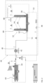
- the purge system 30 additionally includes a movement mechanism 42 arranged upstream, and in some embodiments directly upstream, from an inlet 52 of the separator system 32.
- the movement mechanism 42 may be any suitable device operable to move the purge gas through the purge system 30, including but not limited to a compressor or a diaphragm. As shown, the movement mechanism 42 may be configured to receive purge gas from a purge connection 44 of the condenser 14 and is operable to increase the temperature and pressure of the purge gas provided thereto.
- the purge gas provided at an outlet 46 of the movement mechanism 42 has a pressure greater than 45 psia (310 kPa (absolute)), and in some embodiments equal to or greater than 50 psia (350 kPa (absolute)), 55 psia (380 kPa (absolute)), or 60 psia (410 kPa (absolute)). Accordingly, the pressure of the purge gas itself may be sufficient to drive the flow of purge gas to the separator 32 and/or the flow of refrigerant output from the separator 32 to the condenser 14.
- the separator system 32 also referred to herein as a separator, is operable to separate contaminants from the refrigerant gas.
- an orifice or a valve 48 such as a needle valve for example, is arranged downstream from the refrigerant outlet 56 of the separator 32.
- the orifice 48 may be operable to control the flow rate of the refrigerant recirculated back to an inlet 49 of the condenser 14.
- the flow rate at the orifice 48 is less than the flow rate of the refrigerant and gas combination provided at the outlet 46 of the movement mechanism 42.
- the separator system 32 includes a manifold 50 including an inlet 52 arranged at or near a first end 54 thereof and a refrigerant outlet 56 arranged at or near a second end 58 thereof.
- first end 54 and the second end 58 are illustrated as being at opposite ends of the manifold 50, embodiments where the inlet and outlet are arranged at adjacent sides of the manifold 50, or alternatively, at the same side of the manifold, are also contemplated herein.
- At least one separator 60 also referred to herein as a separator module, is fluidly connected to the manifold 50.
- separators 60 Although two separators 60 are illustrated in the FIGS., it should be understood that embodiments including a single separator 60, as well as embodiments including more than two separators 60, such as three, four, five, six or more separator modules 60 for example, are also within the scope of the disclosure. In embodiments including a plurality of separators 60, a configuration of the plurality of separators 60 may be substantially identical or may vary.
- At least one separator or separator module 60 is arranged at an angle relative to the axis of the manifold 50. As shown, one or more separator modules 60 may be oriented perpendicular relative to the manifold such that the separator module has a substantial vertical orientation.
- a separator module 60 may include a housing 62 having a generally hollow interior 64. Although the housing 62 is shown as being generally cylindrical in shape, it should be understood that a housing 62 having any shape is within the scope of the disclosure.
- the housing 62 includes a fluid inlet 66 and a fluid outlet 68. In the illustrated embodiment, the fluid inlet 66 is arranged adjacent a first end 70 of the housing 62 and is in fluid communication with the interior of the manifold.
- the fluid outlet 68 is spaced from the fluid inlet 66, and may be arranged adjacent a second, opposite end 72 of the housing 62. Although the fluid outlet 68 is illustrated as being arranged generally central along an axis Y defined by the separator module 60, embodiments where the fluid outlet 68 is at another location relative to the separator module housing 62 are also contemplated herein. Because the separator module 60 is oriented vertically, the separator module 60 may also function as a separator, whereby the denser refrigerant liquid will remain near the first end 66 at the bottom, or within the manifold 50, and the less dense refrigerant gas and air will flow upwards, towards the second end 72.
- At least one separating component 34 is mounted within the hollow interior 64 of the housing 62.
- the at least one separating component 34 includes one or more degassing tubes positioned longitudinally within the hollow interior 64 of the housing 62.
- each of the separator tubes includes a body 74 formed from a ceramic zeolite material. A first end of the body 74, such as located adjacent the first end of the housing 62, may be sealed and a second, opposite end of the body 74 may be open and fluidly connected to the fluid outlet 68.
- a refrigerant including contaminants is configured to contact an exterior surface of at least one separating component 34.
- the contaminants separated from the refrigerant may transfer radially inward to an interior of the at least one separating component 34.
- the at least one separating component 34 includes one or more inorganic membranes having a porous surface through which gaseous contaminants, but not liquid refrigerant, can diffuse due to their difference in molecular size.
- the contaminated refrigerant output from the condenser 14 is provided to the movement mechanism 42, where the contaminated refrigerant is pressurized.
- the purge gas is cooled at least partially via conduction, and in some embodiments, heat is transferred to a fluid surrounding the conduit 51, such as ambient air for example.
- a fluid surrounding the conduit 51 such as ambient air for example.
- the refrigerant vapor and air entrained therein flow into the fluid inlet 66 of the one or more separator modules 60.
- the contaminated refrigerant vapor is balanced between the plurality of separator modules 60 fluidly coupled to the manifold 50.
- the contaminated refrigerant contacts the exterior surface of the at least one separating component 34, causing the contaminants, such as air for example, to diffuse through the sidewall and into the hollow interior 76 of the separating component 34. From the hollow interior of the separating component 34, the contaminants may be provided to the fluid outlet 68 where the contaminants may be exhausted from the purge system 30, such as into the ambient atmosphere.
- the liquid refrigerant within the manifold 50 is provided from the outlet 56 to the orifice 48, such as via conduit 53 for example, for return to the heat pump 10.
- the refrigerant outlet 56 at the downstream end of the manifold relative to the refrigerant flow, the refrigerant output from the separator 32 has a reduced concentration of contaminants therein compared to the refrigerant provided to the fluid inlet 52 of the separator 32.
- a purge system 30 as illustrated and described herein has an increased air removal rate compared to existing purge gas systems.
- the gravitational forces acting on the material therein causes a natural separation of the liquid and gaseous components. Accordingly, the denser liquid refrigerant will remain within the manifold and the gaseous contaminants and air will flow into the interior of the separator module housing 62.
- the resulting purge system has a reduced cost and complexity, and an increased efficiency.
Applications Claiming Priority (1)
| Application Number | Priority Date | Filing Date | Title |
|---|---|---|---|
| US202263356330P | 2022-06-28 | 2022-06-28 |
Publications (1)
| Publication Number | Publication Date |
|---|---|
| EP4300010A1 true EP4300010A1 (de) | 2024-01-03 |
Family
ID=86331130
Family Applications (1)
| Application Number | Title | Priority Date | Filing Date |
|---|---|---|---|
| EP23172653.0A Pending EP4300010A1 (de) | 2022-06-28 | 2023-05-10 | Kühlsystem, zugehöriges verfahren zum betrieb eines spülsystems und trennsystem |
Country Status (3)
| Country | Link |
|---|---|
| US (1) | US20230417464A1 (de) |
| EP (1) | EP4300010A1 (de) |
| CN (1) | CN117308421A (de) |
Citations (6)
| Publication number | Priority date | Publication date | Assignee | Title |
|---|---|---|---|---|
| US4417451A (en) * | 1980-05-07 | 1983-11-29 | Hilliard-Lyons Patent Management, Inc. | Vapor compression refrigerant system monitor and gas removal apparatus |
| US5209074A (en) * | 1991-12-18 | 1993-05-11 | E. I. Du Pont De Nemours & Company | High efficiency refrigerant recovery system |
| JP2008096027A (ja) * | 2006-10-12 | 2008-04-24 | Ebara Refrigeration Equipment & Systems Co Ltd | 圧縮式冷凍機の抽気装置 |
| US20130283832A1 (en) * | 2012-04-30 | 2013-10-31 | Trane International Inc. | Refrigeration system with purge using enrivonmentally-suitable chiller refrigerant |
| US20210231354A1 (en) * | 2018-12-03 | 2021-07-29 | Carrier Corporation | Membrane purge system |
| US20210229024A1 (en) * | 2018-12-03 | 2021-07-29 | Carrier Corporation | Enhanced refrigeration purge system |
-
2023
- 2023-05-10 EP EP23172653.0A patent/EP4300010A1/de active Pending
- 2023-06-26 US US18/341,098 patent/US20230417464A1/en active Pending
- 2023-06-26 CN CN202310757566.8A patent/CN117308421A/zh active Pending
Patent Citations (6)
| Publication number | Priority date | Publication date | Assignee | Title |
|---|---|---|---|---|
| US4417451A (en) * | 1980-05-07 | 1983-11-29 | Hilliard-Lyons Patent Management, Inc. | Vapor compression refrigerant system monitor and gas removal apparatus |
| US5209074A (en) * | 1991-12-18 | 1993-05-11 | E. I. Du Pont De Nemours & Company | High efficiency refrigerant recovery system |
| JP2008096027A (ja) * | 2006-10-12 | 2008-04-24 | Ebara Refrigeration Equipment & Systems Co Ltd | 圧縮式冷凍機の抽気装置 |
| US20130283832A1 (en) * | 2012-04-30 | 2013-10-31 | Trane International Inc. | Refrigeration system with purge using enrivonmentally-suitable chiller refrigerant |
| US20210231354A1 (en) * | 2018-12-03 | 2021-07-29 | Carrier Corporation | Membrane purge system |
| US20210229024A1 (en) * | 2018-12-03 | 2021-07-29 | Carrier Corporation | Enhanced refrigeration purge system |
Also Published As
| Publication number | Publication date |
|---|---|
| US20230417464A1 (en) | 2023-12-28 |
| CN117308421A (zh) | 2023-12-29 |
Similar Documents
| Publication | Publication Date | Title |
|---|---|---|
| US11911724B2 (en) | Enhanced refrigeration purge system | |
| US10584906B2 (en) | Refrigeration purge system | |
| US11686515B2 (en) | Membrane purge system | |
| Wu et al. | Alumina-supported AlPO-18 membranes for CO2/CH4 separation | |
| US11913693B2 (en) | Enhanced refrigeration purge system | |
| US6432169B1 (en) | Method and process for drying gas | |
| KR20170100583A (ko) | 흡착제 물질 및 사용 방법 | |
| EP2714241A1 (de) | Zeolithische imidazolatrahmenmembranen, verfahren zu ihrer herstellung und ihre verwendung zur trennung von c2- und c3+-kohlenwasserstoffen sowie zur trennung von propylen- und propanmischungen | |
| US20200149791A1 (en) | Low pressure refrigeration system with membrane purge | |
| EP3483527A1 (de) | Kältemittelreinigungssystem mit membranschutz | |
| CN109764584B (zh) | 低压制冷系统 | |
| AU2020463390A1 (en) | Method and system for dehumidification and atmospheric water extraction with minimal energy consumption | |
| EP4300010A1 (de) | Kühlsystem, zugehöriges verfahren zum betrieb eines spülsystems und trennsystem | |
| US20230384009A1 (en) | Membrane purge system | |
| US11635240B2 (en) | Separator | |
| EP3483530B1 (de) | Kühlspülsystem | |
| US11976860B2 (en) | Enhanced refrigeration purge system | |
| US20210364202A1 (en) | Enhanced refrigeration purge system | |
| WO2017066371A1 (en) | Articles for carbon dioxide capture and methods of making the same |
Legal Events
| Date | Code | Title | Description |
|---|---|---|---|
| PUAI | Public reference made under article 153(3) epc to a published international application that has entered the european phase |
Free format text: ORIGINAL CODE: 0009012 |
|
| STAA | Information on the status of an ep patent application or granted ep patent |
Free format text: STATUS: THE APPLICATION HAS BEEN PUBLISHED |
|
| AK | Designated contracting states |
Kind code of ref document: A1 Designated state(s): AL AT BE BG CH CY CZ DE DK EE ES FI FR GB GR HR HU IE IS IT LI LT LU LV MC ME MK MT NL NO PL PT RO RS SE SI SK SM TR |