EP4300005A1 - Air-conditioning device - Google Patents
Air-conditioning device Download PDFInfo
- Publication number
- EP4300005A1 EP4300005A1 EP21927920.5A EP21927920A EP4300005A1 EP 4300005 A1 EP4300005 A1 EP 4300005A1 EP 21927920 A EP21927920 A EP 21927920A EP 4300005 A1 EP4300005 A1 EP 4300005A1
- Authority
- EP
- European Patent Office
- Prior art keywords
- compressor
- refrigerant
- heat exchanger
- detection value
- value
- Prior art date
- Legal status (The legal status is an assumption and is not a legal conclusion. Google has not performed a legal analysis and makes no representation as to the accuracy of the status listed.)
- Withdrawn
Links
Images





Classifications
-
- F—MECHANICAL ENGINEERING; LIGHTING; HEATING; WEAPONS; BLASTING
- F24—HEATING; RANGES; VENTILATING
- F24F—AIR-CONDITIONING; AIR-HUMIDIFICATION; VENTILATION; USE OF AIR CURRENTS FOR SCREENING
- F24F11/00—Control or safety arrangements
- F24F11/70—Control systems characterised by their outputs; Constructional details thereof
-
- F—MECHANICAL ENGINEERING; LIGHTING; HEATING; WEAPONS; BLASTING
- F25—REFRIGERATION OR COOLING; COMBINED HEATING AND REFRIGERATION SYSTEMS; HEAT PUMP SYSTEMS; MANUFACTURE OR STORAGE OF ICE; LIQUEFACTION SOLIDIFICATION OF GASES
- F25B—REFRIGERATION MACHINES, PLANTS OR SYSTEMS; COMBINED HEATING AND REFRIGERATION SYSTEMS; HEAT PUMP SYSTEMS
- F25B49/00—Arrangement or mounting of control or safety devices
- F25B49/02—Arrangement or mounting of control or safety devices for compression type machines, plants or systems
-
- F—MECHANICAL ENGINEERING; LIGHTING; HEATING; WEAPONS; BLASTING
- F25—REFRIGERATION OR COOLING; COMBINED HEATING AND REFRIGERATION SYSTEMS; HEAT PUMP SYSTEMS; MANUFACTURE OR STORAGE OF ICE; LIQUEFACTION SOLIDIFICATION OF GASES
- F25B—REFRIGERATION MACHINES, PLANTS OR SYSTEMS; COMBINED HEATING AND REFRIGERATION SYSTEMS; HEAT PUMP SYSTEMS
- F25B13/00—Compression machines, plants or systems, with reversible cycle
-
- F—MECHANICAL ENGINEERING; LIGHTING; HEATING; WEAPONS; BLASTING
- F25—REFRIGERATION OR COOLING; COMBINED HEATING AND REFRIGERATION SYSTEMS; HEAT PUMP SYSTEMS; MANUFACTURE OR STORAGE OF ICE; LIQUEFACTION SOLIDIFICATION OF GASES
- F25B—REFRIGERATION MACHINES, PLANTS OR SYSTEMS; COMBINED HEATING AND REFRIGERATION SYSTEMS; HEAT PUMP SYSTEMS
- F25B31/00—Compressor arrangements
- F25B31/002—Lubrication
-
- F—MECHANICAL ENGINEERING; LIGHTING; HEATING; WEAPONS; BLASTING
- F25—REFRIGERATION OR COOLING; COMBINED HEATING AND REFRIGERATION SYSTEMS; HEAT PUMP SYSTEMS; MANUFACTURE OR STORAGE OF ICE; LIQUEFACTION SOLIDIFICATION OF GASES
- F25B—REFRIGERATION MACHINES, PLANTS OR SYSTEMS; COMBINED HEATING AND REFRIGERATION SYSTEMS; HEAT PUMP SYSTEMS
- F25B49/00—Arrangement or mounting of control or safety devices
- F25B49/005—Arrangement or mounting of control or safety devices of safety devices
-
- F—MECHANICAL ENGINEERING; LIGHTING; HEATING; WEAPONS; BLASTING
- F25—REFRIGERATION OR COOLING; COMBINED HEATING AND REFRIGERATION SYSTEMS; HEAT PUMP SYSTEMS; MANUFACTURE OR STORAGE OF ICE; LIQUEFACTION SOLIDIFICATION OF GASES
- F25B—REFRIGERATION MACHINES, PLANTS OR SYSTEMS; COMBINED HEATING AND REFRIGERATION SYSTEMS; HEAT PUMP SYSTEMS
- F25B2313/00—Compression machines, plants or systems with reversible cycle not otherwise provided for
- F25B2313/031—Sensor arrangements
- F25B2313/0312—Pressure sensors near the indoor heat exchanger
-
- F—MECHANICAL ENGINEERING; LIGHTING; HEATING; WEAPONS; BLASTING
- F25—REFRIGERATION OR COOLING; COMBINED HEATING AND REFRIGERATION SYSTEMS; HEAT PUMP SYSTEMS; MANUFACTURE OR STORAGE OF ICE; LIQUEFACTION SOLIDIFICATION OF GASES
- F25B—REFRIGERATION MACHINES, PLANTS OR SYSTEMS; COMBINED HEATING AND REFRIGERATION SYSTEMS; HEAT PUMP SYSTEMS
- F25B2500/00—Problems to be solved
- F25B2500/16—Lubrication
-
- F—MECHANICAL ENGINEERING; LIGHTING; HEATING; WEAPONS; BLASTING
- F25—REFRIGERATION OR COOLING; COMBINED HEATING AND REFRIGERATION SYSTEMS; HEAT PUMP SYSTEMS; MANUFACTURE OR STORAGE OF ICE; LIQUEFACTION SOLIDIFICATION OF GASES
- F25B—REFRIGERATION MACHINES, PLANTS OR SYSTEMS; COMBINED HEATING AND REFRIGERATION SYSTEMS; HEAT PUMP SYSTEMS
- F25B2700/00—Sensing or detecting of parameters; Sensors therefor
- F25B2700/17—Speeds
- F25B2700/171—Speeds of the compressor
-
- F—MECHANICAL ENGINEERING; LIGHTING; HEATING; WEAPONS; BLASTING
- F25—REFRIGERATION OR COOLING; COMBINED HEATING AND REFRIGERATION SYSTEMS; HEAT PUMP SYSTEMS; MANUFACTURE OR STORAGE OF ICE; LIQUEFACTION SOLIDIFICATION OF GASES
- F25B—REFRIGERATION MACHINES, PLANTS OR SYSTEMS; COMBINED HEATING AND REFRIGERATION SYSTEMS; HEAT PUMP SYSTEMS
- F25B2700/00—Sensing or detecting of parameters; Sensors therefor
- F25B2700/21—Temperatures
- F25B2700/2115—Temperatures of a compressor or the drive means therefor
- F25B2700/21151—Temperatures of a compressor or the drive means therefor at the suction side of the compressor
-
- F—MECHANICAL ENGINEERING; LIGHTING; HEATING; WEAPONS; BLASTING
- F25—REFRIGERATION OR COOLING; COMBINED HEATING AND REFRIGERATION SYSTEMS; HEAT PUMP SYSTEMS; MANUFACTURE OR STORAGE OF ICE; LIQUEFACTION SOLIDIFICATION OF GASES
- F25B—REFRIGERATION MACHINES, PLANTS OR SYSTEMS; COMBINED HEATING AND REFRIGERATION SYSTEMS; HEAT PUMP SYSTEMS
- F25B2700/00—Sensing or detecting of parameters; Sensors therefor
- F25B2700/21—Temperatures
- F25B2700/2115—Temperatures of a compressor or the drive means therefor
- F25B2700/21152—Temperatures of a compressor or the drive means therefor at the discharge side of the compressor
Definitions
- the present disclosure relates to an air conditioning apparatus.
- refrigerating machine oil is contained in the compressor.
- the refrigerating machine oil is used to improve lubrication, cooling, sealing, and rust resistance of the compressor.
- the refrigerating machine oil may be discharged, together with refrigerant, into the refrigerant circuit, resulting in a shortage of the refrigerating machine oil in the compressor, relative to a reference amount of the oil.
- the amount or refrigerant contained in the refrigerant circuit should be made smaller than the conventional one, to comply with recent regulations with regard to the refrigerant amount. Under such circumstances, there has recently been a tendency to reduce the amount of refrigerant dissolved in lubricating oil in the compressor, relative to the conventional amount, to thereby reduce the amount of refrigerant contained in the refrigerant circuit, relative to the conventional amount.
- a refrigerating machine oil that makes it possible to reduce the amount of refrigerant dissolved in the lubricating oil in the compressor, relative to the conventional amount
- an incompatible oil having a low compatibility with liquid refrigerant is used.
- the refrigerating machine oil When the incompatible oil is used as the refrigerating machine oil, there is a possibility that the refrigerating machine oil is not dissolved in refrigerant in the refrigerant circuit and is thus separated from the refrigerant, so that the refrigerating machine oil remains in the refrigerant circuit.
- the refrigerating machine oil remains in the refrigerant circuit, the oil return performance that causes the refrigerating machine oil to be returned to the compressor is deteriorated, resulting in a possibility of a further shortage of the refrigerating machine oil in the compressor.
- PTL 1 discloses a technique of performing control to suppress a shortage of refrigerating machine oil, based on comparison between a compressor discharge gas superheat obtained from a detection value of the compressor discharge temperature and a detection value of the compressor discharge pressure, and a threshold value.
- PTL 1 further discloses a technique of performing control to suppress a shortage of refrigerating machine oil, based on comparison between a pressure ratio between a detection value of the compressor suction side pressure and a detection value of the compressor discharge side pressure, and a threshold value.
- PTL 2 discloses a technique of performing control to suppress a shortage of refrigerating machine oil, based on comparison between the degree of subcooling that is obtained based on a detection value of the compressor discharge pressure and a detection value of the heat exchanger outlet temperature, for example, and a threshold value.
- PTL 3 discloses a technique of performing control to suppress a shortage of refrigerating machine oil, based on comparison between a temperature difference between the temperature of refrigerant discharged from the compressor and the temperature of refrigerant sucked into the compressor, and a threshold value.
- the conventional techniques disclosed in PTLs 1 to 3 are each a technique of suppressing a shortage of refrigerating machine oil, by comparing a determination value obtained based on respective detection values of various sensors, with a predetermined threshold value, to determine whether or not there is a shortage of refrigerating machine oil and, when determining that there is a shortage of refrigerating machine oil, perform an operation of collecting refrigerating machine oil.
- the threshold value to be compared with the determination value obtained based on respective detection values of various sensors is a predetermined fixed value, which does take the actual operating state into account, and therefore, there is a possibility that the result of the determination of whether or not there is a shortage of refrigerating machine oil is incorrect. If the result of the determination of whether or not there is a shortage of refrigerating machine oil is incorrect, an unnecessary operation of collecting refrigerating machine oil may be performed, resulting in deterioration of the operational performance, such as reduction of the operational efficiency.
- An object of an air conditioning apparatus of the present disclosure is to suppress deterioration of the operational performance, by enabling accurate identification of a shortage of refrigerating machine oil in the compressor relative to a reference amount of the oil.
- the present disclosure relates to an air conditioning apparatus.
- the air conditioning apparatus includes a refrigerant circuit that includes a compressor, an outdoor heat exchanger, an indoor heat exchanger, and a pressure reducing device, and that is configured to circulate refrigerant; a plurality of sensors configured to detect a state of the refrigerant circuit; and a controller configured to control the refrigerant circuit based on detection results of the plurality of sensors, and the controller is configured to compare a determination value that is obtained based on a detection value of a sensor selected from the plurality of sensors, with a threshold value that is obtained based on a detection value of a sensor selected from the plurality of sensors, and determine, based on a comparison result, whether or not a reference amount of refrigerating machine oil is stored in the compressor.
- a determination value obtained based on a detection value of a sensor selected from a plurality of sensors, and a threshold value obtained based on a detection value of a sensor selected from the plurality of sensors are compared with each other and, based on the result of the comparison, it is determined whether or not a reference amount of refrigerating machine oil is stored in the compressor.
- the threshold value compared with the determination value which is obtained based on the detection value of the sensor is the threshold value which is obtained based on the detection value of the sensor, so that a shortage of refrigerating machine oil in the compressor relative to a reference amount can be identified accurately, in consideration of the operating state of the air conditioning apparatus, and accordingly, deterioration of the operational performance can be suppressed.
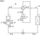
- Fig. 1 shows a configuration of a refrigerant circuit 20 of an air conditioning apparatus 10 according to Embodiment 1.
- the refrigerant circulation direction during heating operation is indicated by solid-line arrows and the refrigerant circulation direction during cooling operation is indicated by solid-line arrows.
- air conditioning apparatus 10 includes a refrigerant circuit, and the refrigerant circuit includes a compressor 1, an indoor heat exchanger 2, a pressure reducing device 3, an outdoor heat exchanger 4, and a flow path switching device 5.
- the refrigerant circuit is a path allowing refrigerant to circulate in air conditioning apparatus 10.
- Outdoor heat exchanger 4 is an air heat exchanger for heat exchange between outdoor air and refrigerant. Outdoor heat exchanger 4 functions as a condenser for a refrigerant during cooling operation, and functions as an evaporator for refrigerant during heating operation. In the vicinity of outdoor heat exchanger 4, a blower fan (not shown) is provided that supplies air to outdoor heat exchanger 4. The blower fan has a function of sucking outdoor air and discharging, to the outside, air having undergone heat exchange with refrigerant in outdoor heat exchanger 4.
- Indoor heat exchanger 2 is a water heat exchanger for heat exchange between water of an indoor unit (not shown) and refrigerant. Indoor heat exchanger 2 functions as an evaporator for refrigerant during cooling operation, and functions as a condenser for refrigerant during heating operation. In the vicinity of indoor heat exchanger 2, a blower fan (not shown) is provided that supplies air to indoor heat exchanger 2. The blower fan has a function of sucking indoor air and discharging into a room, air having undergone heat exchange with refrigerant in indoor heat exchanger 2.
- compressor 1 that compresses refrigerant is provided.
- Compressor 1 is driven by a motor under inverter control, for example.
- pressure reducing device 3 In the refrigerant path between outdoor heat exchanger 4 and indoor heat exchanger 2, pressure reducing device 3 is provided. Outdoor heat exchanger 4, compressor 1, indoor heat exchanger 2, and pressure reducing device 3 are provided to have a series-connected relation in refrigerant circuit 20.
- Pressure reducing device 3 has a function of reducing the pressure of refrigerant to expand the refrigerant, and is configured in the form of an electronic expansion valve capable of adjusting the flow rate, for example. Pressure reducing device 3 is capable of adjusting the flow rate of refrigerant in the refrigerant path during both cooling operation and heating operation, and is used for reducing the pressure of refrigerant to expand the refrigerant.
- Flow path switching device 5 is located between the discharge side of compressor 1 and outdoor heat exchanger 4 and also located between the discharge side thereof and indoor heat exchanger 2.
- the refrigerant path on the discharge side of compressor 1 is connected through flow path switching device 5 to either outdoor heat exchanger 4 or indoor heat exchanger 2.
- Flow path switching device 5 switches the flow path in which refrigerant flows, and is configured in the form of a four-way valve, for example.
- FIG. 2 is a block diagram showing main control components of air conditioning apparatus 10 according to Embodiment 1.
- a controller 100 includes a CPU (Central Processing Unit) 102, a memory 104 (a ROM (Read Only Memory) and a RAM (Random Access Memory)), and an input/output buffer (not shown) for input and output of various signals, for example.
- various electronic components are mounted on a control circuit board.
- the control circuit board includes a plurality of input ports used for input of signals such as detection signals of various sensors, for example, and a plurality of output ports used for output of signals necessary for control of an actuator, such as control signals for compressor 1, pressure reducing device 3, and flow path switching device 5, for example.
- CPU 102 deploys and executes, on the RAM for example, programs stored in the ROM.
- the programs stored in the ROM are each a program in which a process procedure for controller 100 is defined.
- controller 100 controls each device in air conditioning apparatus 10. This control is not limited to processing by software, but may also be processing by dedicated hardware (electronic circuit).
- Air conditioning apparatus 10 is provided with various sensors. Sensors like those as described below are provided, for example.
- Compressor 1 is provided with a first sensor 61 that detects operating frequency F of compressor 1.
- Compressor 1 is provided with a second sensor 62 that detects suction temperature Ts of compressor 1.
- Compressor 1 is provided with a third sensor 63 that detects discharge temperature Td of compressor 1.
- Indoor heat exchanger 2 is provided with a fourth sensor 64 that detects condensation temperature CT.
- Indoor heat exchanger 2 is provided with a fifth sensor 65 that detects refrigerant outlet temperature Tco of indoor heat exchanger 2.
- Indoor heat exchanger 2 is provided with a sixth sensor 66 that detects air intake temperature Tai of indoor heat exchanger 2.
- Indoor heat exchanger 2 is provided with a seventh sensor 67 that detects an air output temperature Tao of indoor heat exchanger 2.
- Respective detection signals of first sensor 61 to seventh sensor 67 are input to controller 100.
- Controller 100 provides respective control signals to compressor 1, pressure reducing device 3, and flow path switching device 5. Based on the control signal, controller 100 controls operating frequency F of compressor 1. Based on the control signal, controller 100 controls the opening of pressure reducing device 3. Based on the control signal, controller 100 performs control to switch the flow path of flow path switching device 5.
- FIGs. 1 and 2 are used to describe operations of air conditioning apparatus 10.
- solid-line arrows indicate the direction in which refrigerant flows during heating operation
- broken-line arrows indicate the direction in which refrigerant flows during cooling operation.
- controller 100 controls flow path switching device 5 to provide the flow paths in flow path switching device 5 as indicated by the solid-line arrows in Fig. 1 .
- Controller 100 controls the opening of pressure reducing device 3 based on the degree of subcooling.
- High-temperature high-pressure gas refrigerant generated through compression and discharged by compressor 1 flows in the refrigerant path through flow path switching device 5 and enters indoor heat exchanger 2.
- the high-temperature high-pressure refrigerant entering indoor heat exchanger 2 discharges heat into water to be condensed into high-pressure liquid refrigerant.
- the high-pressure liquid refrigerant discharged from indoor heat exchanger 2 into the refrigerant path enters pressure reducing device 3 where the liquid refrigerant is expanded to have a reduced pressure and become low-temperature low-pressure gas-liquid two-phase refrigerant.
- the gas-liquid two-phase refrigerant discharged from pressure reducing device 3 enters outdoor heat exchanger 4.
- the gas-liquid two-phase refrigerant entering outdoor heat exchanger 4 exchanges heat with outdoor air to be evaporated into low-temperature low-pressure gas refrigerant.
- the gas refrigerant discharged from outdoor heat exchanger 4 flows through flow path switching device 5 to be sucked into compressor 1 where the gas refrigerant is compressed again.
- controller 100 controls flow path switching device 5 to provide the flow paths in flow path switching device 5 as indicated by the broken-line arrows in Fig. 1 .
- Controller 100 controls the opening of pressure reducing device 3 based on the degree of superheat.
- High-temperature high-pressure gas refrigerant generated through compression and discharged by compressor 1 flows in the refrigerant path through flow path switching device 5 and enters outdoor heat exchanger 4.
- the high-temperature high-pressure refrigerant entering outdoor heat exchanger 4 discharges heat into outdoor air, for example, to be condensed into high-pressure liquid refrigerant.
- the high-pressure liquid refrigerant discharged from outdoor heat exchanger 4 into the refrigerant path enters pressure reducing device 3 where the liquid refrigerant is expanded to have a reduced pressure and become low-temperature low-pressure gas-liquid two-phase refrigerant.
- the gas-liquid two-phase refrigerant discharged from pressure reducing device 3 into the refrigerant path enters indoor heat exchanger 2.
- the gas-liquid two-phase refrigerant entering indoor heat exchanger 2 exchanges heat with water to be evaporated into low-temperature low-pressure gas refrigerant.
- the gas refrigerant discharged from indoor heat exchanger 2 into the refrigerant path flows through flow path switching device 5 to be sucked into compressor 1 where the gas refrigerant is compressed again.
- Fig. 3 shows a relation between compressor 1 and the volumetric efficiency according to Embodiment 1.
- Fig. 3 shows an internal structure of compressor 1, and a graph showing a correlation between the liquid level of refrigerating machine oil and the volumetric efficiency.
- the internal structure of compressor 1 roughly includes a drive unit 12 having a motor, and a mechanical unit 11 having a compressive function and driven by drive unit 12.
- the liquid level in the graph plotting a correlation between the liquid level of refrigerating machine oil and the volumetric efficiency is associated with the liquid level of refrigerating machine oil in compressor 1, where the broken lines indicate the association therebetween.
- the level under which mechanical unit 11 is fully immersed in refrigerating machine oil is a standard level.
- the lower the liquid level of refrigerating machine oil in compressor 1 the lower the volumetric efficiency of compressor 1. This is for the reason that, when the liquid level of refrigerating machine oil in compressor 1 is lowered and accordingly there is a shortage of refrigerating machine oil for mechanical unit 11 relative to a reference amount of the oil, while the refrigeration cycle is stable, the sealing property of mechanical unit 11 is decreased and accordingly the volumetric efficiency of compressor 1 is decreased. As the volumetric efficiency of compressor 1 is decreased, its compressive performance is deteriorated.
- a reference amount of refrigerating machine oil is defined as an amount of oil in a range from a maximum value at which mechanical unit 11 is fully immersed in refrigerating machine oil, to a minimum value at which minimum required compressive performance of mechanical unit 11 is ensured.
- controller 100 determines whether or not the amount of refrigerating machine oil is less than the reference amount and, when controller 100 determines that the amount of refrigerating machine oil is less than the reference amount, controller 100 performs control to implement an oil collecting operation mode of temporarily setting the operating frequency of compressor 1 higher than the operating frequency in a normal operation mode so as to collect refrigerating machine oil, and thereby suppress a shortage of refrigerating machine oil.
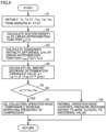
- controller 100 executes an operation control program as shown in Fig. 4 .
- Fig. 4 is a flowchart of the operation control program according to Embodiment 1.
- the operation control program shown in Fig. 4 is executed by CPU 101 of controller 100.
- the operation control program shown in Fig. 4 is executed during heating operation, for example.
- controller 100 obtains, based on respective detection signals that are input from first to seventh sensors 61 to 67, respective detection values of operating frequency F of compressor 1, suction temperature Ts of compressor 1, discharge temperature Td of compressor 1, condensation temperature CT of indoor heat exchanger 2, outlet temperature Tco of indoor heat exchanger 2, air intake temperature Tai of indoor heat exchanger 2, and air output temperature Tao of indoor heat exchanger 2.
- controller 100 calculates suction density ⁇ s by using a linear approximation function "fps(Ts)" in which suction temperature Ts of compressor 1 is a variable, among the detection values obtained in step S1.
- controller 100 calculates condenser enthalpy difference ⁇ Hc using a linear approximation function "f ⁇ Hc (Td,CT,Tco)" in which discharge temperature Td of compressor 1, condensation temperature CT of indoor heat exchanger 2, and outlet temperature Tco of indoor heat exchanger 2 are variables, among detection values obtained in step S1.
- Oil amount decrease determination threshold value ⁇ 1 is a threshold value for determining whether or not it is an oil amount decrease state of the refrigerating machine oil in compressor 1, when "Tao-Tai” is used as a determination value, based on the correlation between the temperature difference "Tao-Tai" between air output temperature Tao of indoor heat exchanger 2 and air intake temperature Tai of indoor heat exchanger 2, and the volumetric efficiency of compressor 1.
- the temperature difference "Tao-Tai” is a determination value used for determining whether or not the amount of refrigerating machine oil stored in compressor 1 is smaller than the lower limit of the range of the reference amount, i.e., a determination value expressed as a temperature difference between air output temperature Tao of indoor heat exchanger 2 and air intake temperature Tai of indoor heat exchanger 2.
- ⁇ is a constant of the volumetric efficiency
- Vst is a constant of the stroke volume
- a 0 K 0 is a constant of the heat exchanger capacity.
- controller 100 compares the oil amount decrease determination threshold value " ⁇ 1" determined in step S4 with the temperature difference "Tao-Tai” based on the detection values obtained in step S1, and determines whether or not " ⁇ 1 > Tao-Tai” is met.
- the normal operation mode is an operation mode in which pressure reducing device 3 is controlled in such a manner that a detection value of discharge temperature Td of compressor 1 is a reference value, for example.
- the oil collecting operation mode is an operation mode in which the operating frequency of compressor 1 is controlled to be temporarily higher than the operating frequency in the normal operation mode, for example, in order to collect refrigerating machine oil into compressor 1.
- Embodiment 1 it can be presumed that the volumetric efficiency of compressor 1 has been decreased, when the value of "Tao-Tai" based on the detection values is smaller than threshold value ⁇ 1, based on the detection values, of "Tao-Tai,” and accordingly, it is determined that there is a shortage of the amount of refrigerating machine oil in compressor 1 relative to the reference amount, and then air conditioning apparatus 10 is operated in the oil collecting operation mode, to thereby collect, into compressor 1, refrigerating machine oil flowing out of compressor 1 into the refrigerant path.
- the determination value "Tao-Tai" which is obtained based on detection values of sensors selected from a plurality of sensors, i.e., first to seventh sensors 61 to 67 detecting a state of the refrigerant circuit, is compared with threshold value ⁇ 1 which is obtained based on detection values of sensors selected from these first to seventh sensors 61 to 67 and, based on the result of the comparison, it is determined whether or not the reference amount of refrigerating machine oil is stored in compressor 1.
- the threshold value compared with the determination value that is obtained based on detection values of first to seventh sensors 61 to 67 is a threshold value that is obtained based on detection values of first to seventh sensors 61 to 67, and therefore, a shortage of refrigerating machine oil in compressor 1 relative to the reference amount can be identified accurately, in consideration of the operating state of air conditioning apparatus 10, to thereby enable suppression of deterioration of the operational performance of air conditioning apparatus 10.
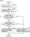
- Embodiment 2 a description is given of another example of the determination process for determining whether or not the reference amount of refrigerating machine oil is stored in compressor 1, as described above in connection with Embodiment 1.
- a detection value of discharge temperature Td (superheat) of compressor 1 is used as the determination value to determine whether or not there is a shortage of refrigerating machine oil in compressor 1.
- Fig. 5 is a flowchart of operation control according to Embodiment 2.
- the operation control program shown in Fig. 5 is executed by CPU 101 of controller 100.
- the operation control program shown in Fig. 5 is executed during heating operation, for example.
- controller 100 obtains, based on respective detection signals that are input from first to seventh sensors 61 to 67, respective detection values of operating frequency F of compressor 1, suction temperature Ts of compressor 1, discharge temperature Td of compressor 1, condensation temperature CT of indoor heat exchanger 2, outlet temperature Tco of indoor heat exchanger 2, air intake temperature Tai of indoor heat exchanger 2, and air output temperature Tao of indoor heat exchanger 2.
- controller 100 calculates respective average values, in a reference time, of respective detection values of operating frequency F, suction temperature Ts, discharge temperature Td, condensation temperature CT, outlet temperature Tco, and "Tao-Tai" among the detection values obtained in step S11.
- controller 100 compares respective average values of operating frequency F, suction temperature Ts, condensation temperature CT, and "Tao-Tai” calculated in step S12, with respective values of operating frequency F, suction temperature Ts, condensation temperature CT, and "Tao-Tai” based on respective detection values obtained in step S11, and determines whether or not the difference between respective values of operating frequency F, suction temperature Ts, condensation temperature CT, and "Tao-Tai” and respective average values is smaller than a constant " ⁇ 2.”
- the constant " ⁇ 2" is a local minimum close to "0.” Specifically, it is determined in step S13 whether or not the difference between respective values of operating frequency F, suction temperature Ts, condensation temperature CT, and "Tao-Tai” based on respective detected values, and respective average values, is sufficiently small.
- step S13 air conditioning apparatus 10 is operated in the normal operation mode in step S15, and the program makes a return.
- the normal operation mode performed in step S15 is an operation mode similar to the normal operation mode performed in step S6 as described above.
- step S13 the average value of discharge temperature Td calculated in step S12 is compared, in step S14, with the detection value of discharge temperature Td obtained in step S11, and it is determined whether or not the difference between the obtained detection value of discharge temperature Td and the average value of discharge temperature Td calculated in step S12 is larger than a constant " ⁇ 3."
- the constant " ⁇ 3" is a value larger than the constant " ⁇ 2.” In other words, it is determined in step S14 whether the difference between the detection value of discharge temperature Td and the average value of discharge temperature Td is not the one that is sufficiently small.
- the constant " ⁇ 2" and the constant " ⁇ 3" may be the same value.
- step S14 air conditioning apparatus 10 is operated in the normal operation mode in step S15, and the program makes a return.
- step S15 air conditioning apparatus 10 is operated in the oil collecting operation mode in step S16, and the program makes a return.
- the oil collecting operation mode performed in step S16 is an operation mode similar to the oil collecting operation mode performed in step S7 as described above.
- Embodiment 2 it can be presumed that the volumetric efficiency of compressor 1 has been decreased, when the difference between respective detection values of operating frequency F, suction temperature Ts, condensation temperature CT, and "Tao-Tai" and respective average values thereof, is sufficiently small and the difference between the detection value of discharge temperature Td and its average value is large to a certain degree or more, and accordingly, it is determined that there is a shortage of the amount of refrigerating machine oil in compressor 1 relative to the reference amount and then air conditioning apparatus 10 is operated in the oil collecting operation mode, to thereby collect, into compressor 1, refrigerating machine oil flowing out of compressor 1 into the refrigerant path.
- discharge temperature Td which is a determination value obtained based on a detection value of a sensor selected from a plurality of sensors, i.e., first to seventh sensors 61 to 67 detecting a state of the refrigerant circuit, is compared with the average value of discharge temperature Td used as a threshold value obtained based on a detection value of the sensor selected from these first to seventh sensors 61 to 67 and, based on the result of the comparison, it is determined whether or not the reference amount of refrigerating machine oil is stored in compressor 1.
- the threshold value compared with the determination value obtained based on a detection value of first to seventh sensors 61 to 67 is the threshold value obtained based on a detection value of first to seventh sensors 61 to 67, and therefore, a shortage of refrigerating machine oil in compressor 1 relative to the reference amount can be identified accurately, in consideration of the operating state of air conditioning apparatus 10, to thereby enable suppression of deterioration in the operational performance of air conditioning apparatus 10.
- Embodiment 3 a description is given of still another example of the determination process for determining whether or not the reference amount of refrigerating machine oil is stored in compressor 1, as described above in connection with Embodiment 1.
- a detection value of outlet temperature Tco (degree of subcooling) of indoor heat exchanger 2 is used as the determination value to determine whether or not there is a shortage of refrigerating machine oil in compressor 1.
- Fig. 6 is a flowchart of operation control according to Embodiment 3.
- the operation control program shown in Fig. 6 is executed by CPU 101 of controller 100.
- the operation control program shown in Fig. 6 is executed during heating operation, for example.
- controller 100 obtains, based on respective detection signals that are input from first to seventh sensors 61 to 67, respective detection values of operating frequency F, suction temperature Ts of compressor 1, discharge temperature Td of compressor 1, condensation temperature CT of indoor heat exchanger 2, outlet temperature Tco of indoor heat exchanger 2, air intake temperature Tai of indoor heat exchanger 2, and air output temperature Tao of indoor heat exchanger 2.
- controller 100 calculates respective average values, in a reference time, of respective detection values of operating frequency F, suction temperature Ts, discharge temperature Td, condensation temperature CT, outlet temperature Tco, and "Tao-Tai" among the detection values obtained in step S2.
- controller 100 compares respective average values of operating frequency F, suction temperature Ts, condensation temperature CT, and "Tao-Tai” calculated in step S22, with respective values of operating frequency F, suction temperature Ts, condensation temperature CT, and "Tao-Tai” based on respective detection values obtained in step S21, and determines whether or not the difference between respective values of operating frequency F, suction temperature Ts, condensation temperature CT, and "Tao-Tai” and respective average values is smaller than a constant " ⁇ 2.”
- the constant " ⁇ 2" is a local minimum close to "0.” Specifically, it is determined in step S23 whether or not the difference between respective values of operating frequency F, suction temperature Ts, condensation temperature CT, and "Tao-Tai” based on respective detected values, and respective average values, is sufficiently small.
- step S23 air conditioning apparatus 10 is operated in the normal operation mode in step S25, and the program makes a return.
- the normal operation mode performed in step S25 is an operation mode similar to the normal operation mode performed in step S6 as described above.
- step S23 the average value of outlet temperature Tco calculated in step S22 is compared, in step S24, with the detection value of outlet temperature Tco obtained in step S21, and it is determined whether or not the difference between the obtained detection value of outlet temperature Tco and the average value of outlet temperature Tco calculated in step S22 is larger than a constant " ⁇ 3."
- the constant " ⁇ 3" is a value larger than the constant " ⁇ 2.” In other words, it is determined in step S24 whether the difference between the detection value of outlet temperature Tco and the average value of outlet temperature Tco is not the one that is sufficiently small.
- the constant “ ⁇ 2” and the constant “ ⁇ 3” may be the same value.
- the constant “ ⁇ 2” used in Embodiment 3 may be the same value as, or a different value from constant " ⁇ 2" used in Embodiment 2.
- the constant “ ⁇ 3” used in Embodiment 3 may be the same value as, or a different value from constant " ⁇ 3" used in Embodiment 2.
- step S24 air conditioning apparatus 10 is operated in the normal operation mode in step S25, and the program makes a return.
- the determination is "YES” in step S25
- air conditioning apparatus 10 is operated in the oil collecting operation mode in step S26, and the program makes a return.
- the normal operation mode performed in step S26 is an operation mode similar to the normal operation mode performed in step S7 as described above.
- Embodiment 3 it can be presumed that the volumetric efficiency of compressor 1 has been decreased, when the difference between respective detection values of operating frequency F, suction temperature Ts, condensation temperature CT, and "Tao-Tai" and respective average values thereof, is sufficiently small and the difference between the detection value of outlet temperature Tco and its average value is large to a certain degree or more, and accordingly, it is determined that there is a shortage of the amount of refrigerating machine oil in compressor 1 relative to the reference amount, and then air conditioning apparatus 10 is operated in the oil collecting operation mode, to thereby collect, into compressor 1, refrigerating machine oil flowing out of compressor 1 into the refrigerant path.
- outlet temperature Tco which is a determination value obtained based on a detection value of a sensor selected from a plurality of sensors, i.e., first to seventh sensors 61 to 67 detecting a state of the refrigerant circuit, is compared with the average value of outlet temperature Tco used as a threshold value obtained based on a detection value of the sensor selected from these first to seventh sensors 61 to 67 and, based on the result of the comparison, it is determined whether or not the reference amount of refrigerating machine oil is stored in compressor 1.
- the threshold value compared with the determination value obtained based on a detection value of first to seventh sensors 61 to 67 is the threshold value obtained based on a detection value of first to seventh sensors 61 to 67, and therefore, a shortage of refrigerating machine oil in compressor 1 relative to the reference amount can be identified accurately, in consideration of the operating state of air conditioning apparatus 10, to thereby enable suppression of deterioration in the operational performance of air conditioning apparatus 10.
- Fig. 7 shows a refrigerant circuit configuration of an air conditioning apparatus 10 according to Embodiment 4.
- the refrigerant circuit configuration shown in Fig. 7 differs from Fig. 1 in that an eighth sensor 68 is provided to detect pressure difference ⁇ P, due to a pressure loss in a part of the section between compressor 1 and pressure reducing device 3.
- Fig. 8 is a block diagram showing main control components of air conditioning apparatus 10 according to Embodiment 4.
- the block diagram shown in Fig. 8 differs from Fig. 1 in that a detection signal of eighth sensor 68 is input to controller 100.
- Fig. 9 is a flowchart of operation control according to Embodiment 4.
- the operation control program shown in Fig. 9 is executed by CPU 101 of controller 100.
- the operation control program shown in Fig. 9 is executed during heating operation.
- controller 100 obtains, based on respective detection signals that are input from first sensor 61, second sensor 62, and eighth sensor 68, respective detection values of operating frequency F of compressor 1, suction temperature Ts of compressor 1, and pressure difference ⁇ P in a part of the section between compressor 1 and pressure reducing device 3.
- controller 100 calculates suction density ⁇ s by using a linear approximation function "fps(Ts)" in which suction temperature Ts of compressor 1 is a variable, among the detection values obtained in step S31.
- Oil amount decrease determination threshold value ⁇ 4 is a threshold value for determining whether or not it is an oil amount decrease state of the refrigerating machine oil in compressor 1, when pressure difference ⁇ P is used as a determination value, based on the correlation between pressure difference ⁇ P in a part of the section between compressor 1 and pressure reducing device 3, and the volumetric efficiency of compressor 1.
- pressure difference ⁇ P is a determination value used for determining whether or not the amount of refrigerating machine oil stored in compressor 1 is smaller than the lower limit of the range of the reference amount.
- ⁇ is a constant of the volumetric efficiency of compressor 1
- ⁇ is a constant of the inner pipe friction factor of a pipe of a refrigerant path
- L is a constant of the pipe length of a part of the section for detecting pressure difference ⁇ P
- d is a constant of the diameter of the pipe of the refrigerant path
- A is a constant of the cross-sectional area of the pipe of the refrigerant path.
- Inner pipe herein refers to the inside of the pipe of the refrigerant path.
- controller 100 compares the oil amount decrease determination threshold value " ⁇ 4" determined in step S32 with pressure difference ⁇ P which is based on the detection values obtained in step S31, and determines whether or not " ⁇ 4 > ⁇ P" is met.
- step S34 When " ⁇ 4 > ⁇ P" is not met in step S34, the amount of refrigerating machine oil in compressor 1 is not less than the reference amount, and therefore, in step S35, air conditioning apparatus 10 is operated in the normal operation mode, and the program makes a return.
- the normal operation mode performed in step S35 is an operation mode similar to the normal operation mode performed in step S6 as described above.
- step S36 air conditioning apparatus 10 is operated in the oil collecting operation mode, and the program makes a return.
- the oil collecting operation mode performed in step S36 is an operation mode similar to the oil collecting operation mode performed in step S7 as described above.
- Embodiment 4 it can be presumed that the volumetric efficiency of compressor 1 has been decreased, when pressure difference ⁇ P based on the detection values is smaller than threshold value ⁇ 4 of pressure difference ⁇ P based on the detection value, and therefore, it is determined that there is a shortage of refrigerating machine oil in compressor 1 relative to the reference amount and then air conditioning apparatus 10 is operated in the oil colleting operation mode, to thereby collect, into compressor 1, refrigerating machine oil flowing out of compressor 1 into the refrigerant path.
- pressure difference ⁇ P which is a determination value obtained based on a detection value of a sensor selected from a plurality of sensors, i.e., first sensor 61, second sensor 62, and eighth sensor 68 detecting a state of the refrigerant circuit, is compared with a threshold value obtained based on detection values of sensors selected from a plurality of sensors, i.e., first sensor 61, second sensor 62, and eighth sensor 68 and, based on the result of the comparison, it is determined whether or not the reference amount of refrigerating machine oil is stored in compressor 1.
- the threshold value compared with the determination value obtained based on a detection value of eighth sensor 68 is the threshold value obtained based on respective detection values of first sensor 61 and second sensor 62, and therefore, a shortage of refrigerating machine oil in compressor 1 relative to the reference amount can be identified accurately, in consideration of the operating state of air conditioning apparatus 10, to thereby enable suppression of deterioration of the operational performance of air conditioning apparatus 10.
- Each of the determination values specified in Embodiments 1 to 4 may at least be a determination value with which it can be presumed that the volumetric efficiency of compressor 1 has been decreased, and other types of determination values may also be used based on respective detection values of multiple types of sensors.
- a state of refrigerant circuit 20 may be detected during cooling operation and, based on the result of the detection, a determination value and a threshold value may be obtained for determining whether or not the reference amount of refrigerating machine oil is stored in compressor 1, to thereby determine whether or not there is a shortage of refrigerating machine oil in compressor 1 relative to the reference amount.
- Embodiment 4 an example is described above in which the detection value of pressure difference ⁇ P due to a pressure loss in a part of the section between compressor 1 and pressure reducing device 3 is used as a determination value to determine whether or not there is a shortage of refrigerating machine oil in compressor 1 relative to the reference amount.
- the part of the section between compressor 1 and pressure reducing device 3 used for such determination is not limited to the partial section between compressor 1 and indoor heat exchanger 2 as described above, and may also be the partial section between indoor heat exchanger 2 and pressure reducing device 3.
- a part of the section between compressor 1 and pressure reducing device 3 used for the determination may be the partial section between compressor 1 and outdoor heat exchanger 4, or the partial section between outdoor heat exchanger 4 and pressure reducing device 3.
- Air conditioning apparatus 10 includes: a refrigerant circuit that includes compressor 1, outdoor heat exchanger 4, indoor heat exchanger 2, and pressure reducing device 3 and that is configured to circulate refrigerant; a plurality of sensors 61 to 68 configured to detect a state of the refrigerant circuit; and controller 100 configured to control the refrigerant circuit based on detection results of the plurality of sensors 61 to 68, and controller 100 is configured to compare a determination value that is obtained based on a detection value of a sensor selected from the plurality of sensors 61 to 68, with a threshold value that is obtained based on a detection value of a sensor selected from the plurality of sensors 61 to 68 (S5, S14, S24, S34), and determine, based on a comparison result, whether or not a reference amount of refrigerating machine oil is stored in the compressor (S5, S14, S24, S34).
- a refrigerant circuit that includes compressor 1, outdoor heat exchanger 4, indoor heat exchanger 2, and pressure reducing device 3 and that is
- the threshold value compared with the determination value that is obtained based on a detection value of a sensor selected from a plurality of sensors 61 to 68 is a threshold value that is obtained based on a detection value of a sensor selected from a plurality of sensors 61 to 68, a shortage of refrigerating machine oil in compressor 1 relative to the reference amount can be identified accurately, in consideration of the operating state of air conditioning apparatus 10, and thus deterioration of the operational performance of air conditioning apparatus 10 can be suppressed.
- the determination value is a temperature difference "Tao-Tai" that is obtained based on a detection value of air output temperature Tao of indoor heat exchanger 2 and a detection value of air intake temperature Tai of indoor heat exchanger 2.
- a temperature difference obtained based on the detection value of air output temperature Tao of indoor heat exchanger 2 and the detection value of air intake temperature Tai of indoor heat exchanger 2 is relevant to decrease of the volumetric efficiency of compressor 1, a shortage of refrigerating machine oil in compressor 1 relative to the reference amount can be identified accurately.
- the determination value is a discharge temperature that is obtained based on a detection value of refrigerant discharge temperature Td of compressor 1.
- the determination value is a detection value of refrigerant outlet temperature Tco of indoor heat exchanger 2.
- the determination value is a detection value of pressure difference T ⁇ due to a pressure loss in a part of a section between compressor 1 and pressure reducing device 3.
- controller 100 obtains the threshold value based on a detection value of operating frequency F of compressor 1, a detection value of refrigerant suction temperature Ts of the compressor, a detection value of refrigerant discharge temperature Td of the compressor, a detection value of refrigerant condensation temperature CT of the indoor heat exchanger, a detection value of refrigerant outlet temperature Tco of the indoor heat exchanger, and a detection value of air output temperature Tao of the indoor heat exchanger.
- controller 100 obtains the threshold value based on an average value of the refrigerant discharge temperature that is obtained from the detection value of refrigerant discharge temperature Td of compressor 1. With such a configuration, since the threshold value is determined in consideration of the actual operating state, the accuracy of the result of the determination of whether or not refrigerating machine oil in compressor 1 is less than the reference amount can be improved.
- controller 100 obtains the threshold value based on an average value of the refrigerant outlet temperature that is obtained from the detection value of refrigerant outlet temperature Tco of indoor heat exchanger 2.
- controller 100 obtains the threshold value based on a detection value of operating frequency F of compressor 1, a detection value of refrigerant suction temperature Ts of compressor 1, and a pressure difference T ⁇ that is obtained based on a detection value of a pressure loss in a part of the section between compressor 1 and pressure reducing device 3.
- controller 100 determines that the reference amount of refrigerating machine oil is not stored
- the controller performs control to cause the compressor to operate in a collecting operation mode of colleting refrigerating machine oil having flown out of compressor 1 into the refrigerant circuit (S7, S16, S26, S36).
- the control is carried out to cause the compressor to operate in the collecting operation mode of collecting refrigerating machine oil having flown out of compressor 1 into the refrigerant circuit, and therefore, execution of an unnecessary operation of collecting refrigerating machine oil can be suppressed to thereby improve the operational efficiency.
- the threshold value compared with the determination value obtained based on the detection values of sensors 61 to 68 is a threshold value obtained based on detection values of sensors 61 to 68, and therefore, a shortage of refrigerating machine oil in compressor 1 relative to the reference amount can be identified accurately, and thus deterioration of the operational performance can be suppressed.
Landscapes
- Engineering & Computer Science (AREA)
- Mechanical Engineering (AREA)
- General Engineering & Computer Science (AREA)
- Physics & Mathematics (AREA)
- Thermal Sciences (AREA)
- Chemical & Material Sciences (AREA)
- Combustion & Propulsion (AREA)
- Air Conditioning Control Device (AREA)
Abstract
Description
- The present disclosure relates to an air conditioning apparatus.
- In an air conditioning apparatus equipped with a refrigerant circuit that includes a compressor, an outdoor heat exchanger, an indoor heat exchanger, and a pressure reducing device and causes refrigerant to circulate, refrigerating machine oil is contained in the compressor. The refrigerating machine oil is used to improve lubrication, cooling, sealing, and rust resistance of the compressor. During operation of the air conditioning apparatus, however, the refrigerating machine oil may be discharged, together with refrigerant, into the refrigerant circuit, resulting in a shortage of the refrigerating machine oil in the compressor, relative to a reference amount of the oil.
- The amount or refrigerant contained in the refrigerant circuit should be made smaller than the conventional one, to comply with recent regulations with regard to the refrigerant amount. Under such circumstances, there has recently been a tendency to reduce the amount of refrigerant dissolved in lubricating oil in the compressor, relative to the conventional amount, to thereby reduce the amount of refrigerant contained in the refrigerant circuit, relative to the conventional amount. As a refrigerating machine oil that makes it possible to reduce the amount of refrigerant dissolved in the lubricating oil in the compressor, relative to the conventional amount, an incompatible oil having a low compatibility with liquid refrigerant is used.
- When the incompatible oil is used as the refrigerating machine oil, there is a possibility that the refrigerating machine oil is not dissolved in refrigerant in the refrigerant circuit and is thus separated from the refrigerant, so that the refrigerating machine oil remains in the refrigerant circuit. When the refrigerating machine oil remains in the refrigerant circuit, the oil return performance that causes the refrigerating machine oil to be returned to the compressor is deteriorated, resulting in a possibility of a further shortage of the refrigerating machine oil in the compressor.
- The following are techniques for suppressing a shortage of refrigerating machine oil in the compressor of conventional air conditioning apparatuses.
PTL 1 discloses a technique of performing control to suppress a shortage of refrigerating machine oil, based on comparison between a compressor discharge gas superheat obtained from a detection value of the compressor discharge temperature and a detection value of the compressor discharge pressure, and a threshold value.PTL 1 further discloses a technique of performing control to suppress a shortage of refrigerating machine oil, based on comparison between a pressure ratio between a detection value of the compressor suction side pressure and a detection value of the compressor discharge side pressure, and a threshold value. -
PTL 2 discloses a technique of performing control to suppress a shortage of refrigerating machine oil, based on comparison between the degree of subcooling that is obtained based on a detection value of the compressor discharge pressure and a detection value of the heat exchanger outlet temperature, for example, and a threshold value.PTL 3 discloses a technique of performing control to suppress a shortage of refrigerating machine oil, based on comparison between a temperature difference between the temperature of refrigerant discharged from the compressor and the temperature of refrigerant sucked into the compressor, and a threshold value. -
- PTL 1:
Japanese Patent Laying-Open No. 2011-117626 - PTL 2:
Japanese Patent Laying-Open No. 2017-156003 - PTL 3:
Japanese Patent Laying-Open No. 2018-004106 - The conventional techniques disclosed in
PTLs 1 to 3 are each a technique of suppressing a shortage of refrigerating machine oil, by comparing a determination value obtained based on respective detection values of various sensors, with a predetermined threshold value, to determine whether or not there is a shortage of refrigerating machine oil and, when determining that there is a shortage of refrigerating machine oil, perform an operation of collecting refrigerating machine oil. - According to the conventional techniques disclosed in
PTLs 1 to 3, however, the threshold value to be compared with the determination value obtained based on respective detection values of various sensors, is a predetermined fixed value, which does take the actual operating state into account, and therefore, there is a possibility that the result of the determination of whether or not there is a shortage of refrigerating machine oil is incorrect. If the result of the determination of whether or not there is a shortage of refrigerating machine oil is incorrect, an unnecessary operation of collecting refrigerating machine oil may be performed, resulting in deterioration of the operational performance, such as reduction of the operational efficiency. - An object of an air conditioning apparatus of the present disclosure is to suppress deterioration of the operational performance, by enabling accurate identification of a shortage of refrigerating machine oil in the compressor relative to a reference amount of the oil.
- The present disclosure relates to an air conditioning apparatus. The air conditioning apparatus includes a refrigerant circuit that includes a compressor, an outdoor heat exchanger, an indoor heat exchanger, and a pressure reducing device, and that is configured to circulate refrigerant; a plurality of sensors configured to detect a state of the refrigerant circuit; and a controller configured to control the refrigerant circuit based on detection results of the plurality of sensors, and the controller is configured to compare a determination value that is obtained based on a detection value of a sensor selected from the plurality of sensors, with a threshold value that is obtained based on a detection value of a sensor selected from the plurality of sensors, and determine, based on a comparison result, whether or not a reference amount of refrigerating machine oil is stored in the compressor.
- For the air conditioning apparatus of the present disclosure, a determination value obtained based on a detection value of a sensor selected from a plurality of sensors, and a threshold value obtained based on a detection value of a sensor selected from the plurality of sensors, are compared with each other and, based on the result of the comparison, it is determined whether or not a reference amount of refrigerating machine oil is stored in the compressor. Thus, for the air conditioning apparatus of the present disclosure, the threshold value compared with the determination value which is obtained based on the detection value of the sensor is the threshold value which is obtained based on the detection value of the sensor, so that a shortage of refrigerating machine oil in the compressor relative to a reference amount can be identified accurately, in consideration of the operating state of the air conditioning apparatus, and accordingly, deterioration of the operational performance can be suppressed.
-
-
Fig. 1 shows a refrigerant circuit configuration of anair conditioning apparatus 10 according toEmbodiment 1. -
Fig. 2 is a block diagram showing main control components ofair conditioning apparatus 10 according toEmbodiment 1. -
Fig. 3 shows a relation between acompressor 1 and the volumetric efficiency according toEmbodiment 1. -
Fig. 4 is a flowchart of an operation control program according toEmbodiment 1. -
Fig. 5 is a flowchart of an operation control program according toEmbodiment 2. -
Fig. 6 is a flowchart of an operation control program according toEmbodiment 3. -
Fig. 7 shows a refrigerant circuit configuration of anair conditioning apparatus 10 according toEmbodiment 4. -
Fig. 8 is a block diagram showing main control components ofair conditioning apparatus 10 according toEmbodiment 4. -
Fig. 9 is a flowchart of an operation control program according to Embodiment 4. - In the following, embodiments of the present disclosure are described in detail with reference to the drawings. While a plurality of embodiments are hereinafter described, it is intended originally at the time of application filing to appropriately combine features described in connection with the embodiments. In the drawings, the same or corresponding parts are denoted by the same reference characters, and description thereof is not herein repeated.
-
Fig. 1 shows a configuration of arefrigerant circuit 20 of anair conditioning apparatus 10 according toEmbodiment 1. InFig. 1 , the refrigerant circulation direction during heating operation is indicated by solid-line arrows and the refrigerant circulation direction during cooling operation is indicated by solid-line arrows. - Referring to
Fig. 1 ,air conditioning apparatus 10 includes a refrigerant circuit, and the refrigerant circuit includes acompressor 1, anindoor heat exchanger 2, apressure reducing device 3, anoutdoor heat exchanger 4, and a flowpath switching device 5. The refrigerant circuit is a path allowing refrigerant to circulate inair conditioning apparatus 10. -
Outdoor heat exchanger 4 is an air heat exchanger for heat exchange between outdoor air and refrigerant.Outdoor heat exchanger 4 functions as a condenser for a refrigerant during cooling operation, and functions as an evaporator for refrigerant during heating operation. In the vicinity ofoutdoor heat exchanger 4, a blower fan (not shown) is provided that supplies air tooutdoor heat exchanger 4. The blower fan has a function of sucking outdoor air and discharging, to the outside, air having undergone heat exchange with refrigerant inoutdoor heat exchanger 4. -
Indoor heat exchanger 2 is a water heat exchanger for heat exchange between water of an indoor unit (not shown) and refrigerant.Indoor heat exchanger 2 functions as an evaporator for refrigerant during cooling operation, and functions as a condenser for refrigerant during heating operation. In the vicinity ofindoor heat exchanger 2, a blower fan (not shown) is provided that supplies air toindoor heat exchanger 2. The blower fan has a function of sucking indoor air and discharging into a room, air having undergone heat exchange with refrigerant inindoor heat exchanger 2. - In a refrigerant path between
outdoor heat exchanger 4 andindoor heat exchanger 2,compressor 1 that compresses refrigerant is provided.Compressor 1 is driven by a motor under inverter control, for example. - In the refrigerant path between
outdoor heat exchanger 4 andindoor heat exchanger 2,pressure reducing device 3 is provided.Outdoor heat exchanger 4,compressor 1,indoor heat exchanger 2, andpressure reducing device 3 are provided to have a series-connected relation inrefrigerant circuit 20. -
Pressure reducing device 3 has a function of reducing the pressure of refrigerant to expand the refrigerant, and is configured in the form of an electronic expansion valve capable of adjusting the flow rate, for example.Pressure reducing device 3 is capable of adjusting the flow rate of refrigerant in the refrigerant path during both cooling operation and heating operation, and is used for reducing the pressure of refrigerant to expand the refrigerant. - Flow
path switching device 5 is located between the discharge side ofcompressor 1 andoutdoor heat exchanger 4 and also located between the discharge side thereof andindoor heat exchanger 2. The refrigerant path on the discharge side ofcompressor 1 is connected through flowpath switching device 5 to eitheroutdoor heat exchanger 4 orindoor heat exchanger 2. Flowpath switching device 5 switches the flow path in which refrigerant flows, and is configured in the form of a four-way valve, for example. - Next, main control components of
air conditioning apparatus 10 are described.Fig. 2 is a block diagram showing main control components ofair conditioning apparatus 10 according toEmbodiment 1. - A
controller 100 includes a CPU (Central Processing Unit) 102, a memory 104 (a ROM (Read Only Memory) and a RAM (Random Access Memory)), and an input/output buffer (not shown) for input and output of various signals, for example. In the controller, various electronic components are mounted on a control circuit board. The control circuit board includes a plurality of input ports used for input of signals such as detection signals of various sensors, for example, and a plurality of output ports used for output of signals necessary for control of an actuator, such as control signals forcompressor 1,pressure reducing device 3, and flowpath switching device 5, for example. -
CPU 102 deploys and executes, on the RAM for example, programs stored in the ROM. The programs stored in the ROM are each a program in which a process procedure forcontroller 100 is defined. In accordance with these programs,controller 100 controls each device inair conditioning apparatus 10. This control is not limited to processing by software, but may also be processing by dedicated hardware (electronic circuit). -
Air conditioning apparatus 10 is provided with various sensors. Sensors like those as described below are provided, for example.Compressor 1 is provided with afirst sensor 61 that detects operating frequency F ofcompressor 1.Compressor 1 is provided with asecond sensor 62 that detects suction temperature Ts ofcompressor 1.Compressor 1 is provided with athird sensor 63 that detects discharge temperature Td ofcompressor 1.Indoor heat exchanger 2 is provided with afourth sensor 64 that detects condensation temperature CT.Indoor heat exchanger 2 is provided with afifth sensor 65 that detects refrigerant outlet temperature Tco ofindoor heat exchanger 2.Indoor heat exchanger 2 is provided with asixth sensor 66 that detects air intake temperature Tai ofindoor heat exchanger 2.Indoor heat exchanger 2 is provided with aseventh sensor 67 that detects an air output temperature Tao ofindoor heat exchanger 2. - Respective detection signals of
first sensor 61 toseventh sensor 67 are input tocontroller 100.Controller 100 provides respective control signals tocompressor 1,pressure reducing device 3, and flowpath switching device 5. Based on the control signal,controller 100 controls operating frequency F ofcompressor 1. Based on the control signal,controller 100 controls the opening ofpressure reducing device 3. Based on the control signal,controller 100 performs control to switch the flow path of flowpath switching device 5. - Next,
Figs. 1 and2 are used to describe operations ofair conditioning apparatus 10. InFig. 1 , solid-line arrows indicate the direction in which refrigerant flows during heating operation, and broken-line arrows indicate the direction in which refrigerant flows during cooling operation. - First, an operation of
air conditioning apparatus 10 during heating operation is described. During heating operation,controller 100 controls flowpath switching device 5 to provide the flow paths in flowpath switching device 5 as indicated by the solid-line arrows inFig. 1 .Controller 100 controls the opening ofpressure reducing device 3 based on the degree of subcooling. - High-temperature high-pressure gas refrigerant generated through compression and discharged by
compressor 1 flows in the refrigerant path through flowpath switching device 5 and entersindoor heat exchanger 2. The high-temperature high-pressure refrigerant enteringindoor heat exchanger 2 discharges heat into water to be condensed into high-pressure liquid refrigerant. In the refrigerant path, the high-pressure liquid refrigerant discharged fromindoor heat exchanger 2 into the refrigerant path enterspressure reducing device 3 where the liquid refrigerant is expanded to have a reduced pressure and become low-temperature low-pressure gas-liquid two-phase refrigerant. In the refrigerant path, the gas-liquid two-phase refrigerant discharged frompressure reducing device 3 entersoutdoor heat exchanger 4. The gas-liquid two-phase refrigerant enteringoutdoor heat exchanger 4 exchanges heat with outdoor air to be evaporated into low-temperature low-pressure gas refrigerant. The gas refrigerant discharged fromoutdoor heat exchanger 4 flows through flowpath switching device 5 to be sucked intocompressor 1 where the gas refrigerant is compressed again. - Next, an operation of
air conditioning apparatus 10 during cooling operation is described. During cooling operation,controller 100 controls flowpath switching device 5 to provide the flow paths in flowpath switching device 5 as indicated by the broken-line arrows inFig. 1 .Controller 100 controls the opening ofpressure reducing device 3 based on the degree of superheat. - High-temperature high-pressure gas refrigerant generated through compression and discharged by
compressor 1 flows in the refrigerant path through flowpath switching device 5 and entersoutdoor heat exchanger 4. The high-temperature high-pressure refrigerant enteringoutdoor heat exchanger 4 discharges heat into outdoor air, for example, to be condensed into high-pressure liquid refrigerant. The high-pressure liquid refrigerant discharged fromoutdoor heat exchanger 4 into the refrigerant path enterspressure reducing device 3 where the liquid refrigerant is expanded to have a reduced pressure and become low-temperature low-pressure gas-liquid two-phase refrigerant. The gas-liquid two-phase refrigerant discharged frompressure reducing device 3 into the refrigerant path entersindoor heat exchanger 2. The gas-liquid two-phase refrigerant enteringindoor heat exchanger 2 exchanges heat with water to be evaporated into low-temperature low-pressure gas refrigerant. The gas refrigerant discharged fromindoor heat exchanger 2 into the refrigerant path flows through flowpath switching device 5 to be sucked intocompressor 1 where the gas refrigerant is compressed again. - Next, a relation between the liquid level of refrigerating machine oil contained in
compressor 1 and the volumetric efficiency ofcompressor 1.Fig. 3 shows a relation betweencompressor 1 and the volumetric efficiency according toEmbodiment 1.Fig. 3 shows an internal structure ofcompressor 1, and a graph showing a correlation between the liquid level of refrigerating machine oil and the volumetric efficiency. - Referring to
Fig. 3 , the internal structure ofcompressor 1 roughly includes adrive unit 12 having a motor, and amechanical unit 11 having a compressive function and driven bydrive unit 12. InFig. 3 , the liquid level in the graph plotting a correlation between the liquid level of refrigerating machine oil and the volumetric efficiency is associated with the liquid level of refrigerating machine oil incompressor 1, where the broken lines indicate the association therebetween. - Referring to
Fig. 3 , regarding the liquid level of refrigerating machine oil incompressor 1, the level under whichmechanical unit 11 is fully immersed in refrigerating machine oil, for example, is a standard level. As illustrated by the graph, the lower the liquid level of refrigerating machine oil incompressor 1, the lower the volumetric efficiency ofcompressor 1. This is for the reason that, when the liquid level of refrigerating machine oil incompressor 1 is lowered and accordingly there is a shortage of refrigerating machine oil formechanical unit 11 relative to a reference amount of the oil, while the refrigeration cycle is stable, the sealing property ofmechanical unit 11 is decreased and accordingly the volumetric efficiency ofcompressor 1 is decreased. As the volumetric efficiency ofcompressor 1 is decreased, its compressive performance is deteriorated. - Regarding the amount of refrigerating machine oil stored in
compressor 1, a reference amount of refrigerating machine oil is defined as an amount of oil in a range from a maximum value at whichmechanical unit 11 is fully immersed in refrigerating machine oil, to a minimum value at which minimum required compressive performance ofmechanical unit 11 is ensured. - In
air conditioning apparatus 10,controller 100 determines whether or not the amount of refrigerating machine oil is less than the reference amount and, whencontroller 100 determines that the amount of refrigerating machine oil is less than the reference amount,controller 100 performs control to implement an oil collecting operation mode of temporarily setting the operating frequency ofcompressor 1 higher than the operating frequency in a normal operation mode so as to collect refrigerating machine oil, and thereby suppress a shortage of refrigerating machine oil. - In order to thus determine whether or not the amount of refrigerating machine oil is less than the reference amount, and perform control to operate
air conditioning apparatus 10 in either the normal operation mode or the collecting operation mode based on the result of the determination,controller 100 executes an operation control program as shown inFig. 4 . -
Fig. 4 is a flowchart of the operation control program according toEmbodiment 1. The operation control program shown inFig. 4 is executed byCPU 101 ofcontroller 100. The operation control program shown inFig. 4 is executed during heating operation, for example. - In step S1,
controller 100 obtains, based on respective detection signals that are input from first toseventh sensors 61 to 67, respective detection values of operating frequency F ofcompressor 1, suction temperature Ts ofcompressor 1, discharge temperature Td ofcompressor 1, condensation temperature CT ofindoor heat exchanger 2, outlet temperature Tco ofindoor heat exchanger 2, air intake temperature Tai ofindoor heat exchanger 2, and air output temperature Tao ofindoor heat exchanger 2. - In step S2,
controller 100 calculates suction density ρs by using a linear approximation function "fps(Ts)" in which suction temperature Ts ofcompressor 1 is a variable, among the detection values obtained in step S1. Next, in step S3,controller 100 calculates condenser enthalpy difference ΔHc using a linear approximation function "fΔHc(Td,CT,Tco)" in which discharge temperature Td ofcompressor 1, condensation temperature CT ofindoor heat exchanger 2, and outlet temperature Tco ofindoor heat exchanger 2 are variables, among detection values obtained in step S1. - Next, in step S4,
controller 100 calculates oil amount decrease determination threshold value α1 by using an arithmetic expression "α1 = β1 × ρs × F × ΔHc." Oil amount decrease determination threshold value α1 is a threshold value for determining whether or not it is an oil amount decrease state of the refrigerating machine oil incompressor 1, when "Tao-Tai" is used as a determination value, based on the correlation between the temperature difference "Tao-Tai" between air output temperature Tao ofindoor heat exchanger 2 and air intake temperature Tai ofindoor heat exchanger 2, and the volumetric efficiency ofcompressor 1. Specifically, the temperature difference "Tao-Tai" is a determination value used for determining whether or not the amount of refrigerating machine oil stored incompressor 1 is smaller than the lower limit of the range of the reference amount, i.e., a determination value expressed as a temperature difference between air output temperature Tao ofindoor heat exchanger 2 and air intake temperature Tai ofindoor heat exchanger 2. "β1" is a constant determined by an arithmetic expression "β1 = η × Vst × (A0K0)-1." Here, "η" is a constant of the volumetric efficiency, "Vst" is a constant of the stroke volume, and "A0K0" is a constant of the heat exchanger capacity. - Next, in step S5,
controller 100 compares the oil amount decrease determination threshold value "α1" determined in step S4 with the temperature difference "Tao-Tai" based on the detection values obtained in step S1, and determines whether or not "α1 > Tao-Tai" is met. - When "α1 > Tao-Tai" is not met in step S5, the amount of refrigerating machine oil in
compressor 1 is not less than the reference amount, and therefore, in step S6,air conditioning apparatus 10 is operated in the normal operation mode, and the program makes a return. The normal operation mode is an operation mode in whichpressure reducing device 3 is controlled in such a manner that a detection value of discharge temperature Td ofcompressor 1 is a reference value, for example. When "α1 > Tao-Tai" is met in step S5, the amount of refrigerating machine oil incompressor 1 is less than the reference amount, and therefore, in step S7,air conditioning apparatus 10 is operated in the oil collecting operation mode, and the program makes a return. The oil collecting operation mode is an operation mode in which the operating frequency ofcompressor 1 is controlled to be temporarily higher than the operating frequency in the normal operation mode, for example, in order to collect refrigerating machine oil intocompressor 1. - According to
Embodiment 1, it can be presumed that the volumetric efficiency ofcompressor 1 has been decreased, when the value of "Tao-Tai" based on the detection values is smaller than threshold value α1, based on the detection values, of "Tao-Tai," and accordingly, it is determined that there is a shortage of the amount of refrigerating machine oil incompressor 1 relative to the reference amount, and thenair conditioning apparatus 10 is operated in the oil collecting operation mode, to thereby collect, intocompressor 1, refrigerating machine oil flowing out ofcompressor 1 into the refrigerant path. - According to
Embodiment 1 as described above, the determination value "Tao-Tai" which is obtained based on detection values of sensors selected from a plurality of sensors, i.e., first toseventh sensors 61 to 67 detecting a state of the refrigerant circuit, is compared with threshold value α1 which is obtained based on detection values of sensors selected from these first toseventh sensors 61 to 67 and, based on the result of the comparison, it is determined whether or not the reference amount of refrigerating machine oil is stored incompressor 1. Thus, the threshold value compared with the determination value that is obtained based on detection values of first toseventh sensors 61 to 67 is a threshold value that is obtained based on detection values of first toseventh sensors 61 to 67, and therefore, a shortage of refrigerating machine oil incompressor 1 relative to the reference amount can be identified accurately, in consideration of the operating state ofair conditioning apparatus 10, to thereby enable suppression of deterioration of the operational performance ofair conditioning apparatus 10. - In connection with
Embodiment 2, a description is given of another example of the determination process for determining whether or not the reference amount of refrigerating machine oil is stored incompressor 1, as described above in connection withEmbodiment 1. In connection withEmbodiment 2, an example is described in which a detection value of discharge temperature Td (superheat) ofcompressor 1 is used as the determination value to determine whether or not there is a shortage of refrigerating machine oil incompressor 1. -
Fig. 5 is a flowchart of operation control according toEmbodiment 2. The operation control program shown inFig. 5 is executed byCPU 101 ofcontroller 100. The operation control program shown inFig. 5 is executed during heating operation, for example. - In step 511,
controller 100 obtains, based on respective detection signals that are input from first toseventh sensors 61 to 67, respective detection values of operating frequency F ofcompressor 1, suction temperature Ts ofcompressor 1, discharge temperature Td ofcompressor 1, condensation temperature CT ofindoor heat exchanger 2, outlet temperature Tco ofindoor heat exchanger 2, air intake temperature Tai ofindoor heat exchanger 2, and air output temperature Tao ofindoor heat exchanger 2. - In step S12,
controller 100 calculates respective average values, in a reference time, of respective detection values of operating frequency F, suction temperature Ts, discharge temperature Td, condensation temperature CT, outlet temperature Tco, and "Tao-Tai" among the detection values obtained in step S11. Next, in step S13,controller 100 compares respective average values of operating frequency F, suction temperature Ts, condensation temperature CT, and "Tao-Tai" calculated in step S12, with respective values of operating frequency F, suction temperature Ts, condensation temperature CT, and "Tao-Tai" based on respective detection values obtained in step S11, and determines whether or not the difference between respective values of operating frequency F, suction temperature Ts, condensation temperature CT, and "Tao-Tai" and respective average values is smaller than a constant "α2." The constant "α2" is a local minimum close to "0." Specifically, it is determined in step S13 whether or not the difference between respective values of operating frequency F, suction temperature Ts, condensation temperature CT, and "Tao-Tai" based on respective detected values, and respective average values, is sufficiently small. - When the determination is "NO" in step S13,
air conditioning apparatus 10 is operated in the normal operation mode in step S15, and the program makes a return. The normal operation mode performed in step S15 is an operation mode similar to the normal operation mode performed in step S6 as described above. In contrast, when the determination is "YES" in step S13, the average value of discharge temperature Td calculated in step S12 is compared, in step S14, with the detection value of discharge temperature Td obtained in step S11, and it is determined whether or not the difference between the obtained detection value of discharge temperature Td and the average value of discharge temperature Td calculated in step S12 is larger than a constant "α3." The constant "α3" is a value larger than the constant "α2." In other words, it is determined in step S14 whether the difference between the detection value of discharge temperature Td and the average value of discharge temperature Td is not the one that is sufficiently small. The constant "α2" and the constant "α3" may be the same value. - When the determination is "NO" in step S14,
air conditioning apparatus 10 is operated in the normal operation mode in step S15, and the program makes a return. In contrast, when the determination is "YES" in step S15,air conditioning apparatus 10 is operated in the oil collecting operation mode in step S16, and the program makes a return. The oil collecting operation mode performed in step S16 is an operation mode similar to the oil collecting operation mode performed in step S7 as described above. - According to
Embodiment 2, it can be presumed that the volumetric efficiency ofcompressor 1 has been decreased, when the difference between respective detection values of operating frequency F, suction temperature Ts, condensation temperature CT, and "Tao-Tai" and respective average values thereof, is sufficiently small and the difference between the detection value of discharge temperature Td and its average value is large to a certain degree or more, and accordingly, it is determined that there is a shortage of the amount of refrigerating machine oil incompressor 1 relative to the reference amount and thenair conditioning apparatus 10 is operated in the oil collecting operation mode, to thereby collect, intocompressor 1, refrigerating machine oil flowing out ofcompressor 1 into the refrigerant path. - According to
Embodiment 2 as described above, discharge temperature Td which is a determination value obtained based on a detection value of a sensor selected from a plurality of sensors, i.e., first toseventh sensors 61 to 67 detecting a state of the refrigerant circuit, is compared with the average value of discharge temperature Td used as a threshold value obtained based on a detection value of the sensor selected from these first toseventh sensors 61 to 67 and, based on the result of the comparison, it is determined whether or not the reference amount of refrigerating machine oil is stored incompressor 1. Thus, the threshold value compared with the determination value obtained based on a detection value of first toseventh sensors 61 to 67, is the threshold value obtained based on a detection value of first toseventh sensors 61 to 67, and therefore, a shortage of refrigerating machine oil incompressor 1 relative to the reference amount can be identified accurately, in consideration of the operating state ofair conditioning apparatus 10, to thereby enable suppression of deterioration in the operational performance ofair conditioning apparatus 10. - In connection with
Embodiment 3, a description is given of still another example of the determination process for determining whether or not the reference amount of refrigerating machine oil is stored incompressor 1, as described above in connection withEmbodiment 1. In connection withEmbodiment 3, an example is described in which a detection value of outlet temperature Tco (degree of subcooling) ofindoor heat exchanger 2 is used as the determination value to determine whether or not there is a shortage of refrigerating machine oil incompressor 1. -
Fig. 6 is a flowchart of operation control according toEmbodiment 3. The operation control program shown inFig. 6 is executed byCPU 101 ofcontroller 100. The operation control program shown inFig. 6 is executed during heating operation, for example. - In step S21,
controller 100 obtains, based on respective detection signals that are input from first toseventh sensors 61 to 67, respective detection values of operating frequency F, suction temperature Ts ofcompressor 1, discharge temperature Td ofcompressor 1, condensation temperature CT ofindoor heat exchanger 2, outlet temperature Tco ofindoor heat exchanger 2, air intake temperature Tai ofindoor heat exchanger 2, and air output temperature Tao ofindoor heat exchanger 2. - In step S22,
controller 100 calculates respective average values, in a reference time, of respective detection values of operating frequency F, suction temperature Ts, discharge temperature Td, condensation temperature CT, outlet temperature Tco, and "Tao-Tai" among the detection values obtained in step S2. Next, in step S23,controller 100 compares respective average values of operating frequency F, suction temperature Ts, condensation temperature CT, and "Tao-Tai" calculated in step S22, with respective values of operating frequency F, suction temperature Ts, condensation temperature CT, and "Tao-Tai" based on respective detection values obtained in step S21, and determines whether or not the difference between respective values of operating frequency F, suction temperature Ts, condensation temperature CT, and "Tao-Tai" and respective average values is smaller than a constant "α2." The constant "α2" is a local minimum close to "0." Specifically, it is determined in step S23 whether or not the difference between respective values of operating frequency F, suction temperature Ts, condensation temperature CT, and "Tao-Tai" based on respective detected values, and respective average values, is sufficiently small. - When the determination is "NO" in step S23,
air conditioning apparatus 10 is operated in the normal operation mode in step S25, and the program makes a return. The normal operation mode performed in step S25 is an operation mode similar to the normal operation mode performed in step S6 as described above. In contrast, when the determination is "YES" in step S23, the average value of outlet temperature Tco calculated in step S22 is compared, in step S24, with the detection value of outlet temperature Tco obtained in step S21, and it is determined whether or not the difference between the obtained detection value of outlet temperature Tco and the average value of outlet temperature Tco calculated in step S22 is larger than a constant "α3." The constant "α3" is a value larger than the constant "α2." In other words, it is determined in step S24 whether the difference between the detection value of outlet temperature Tco and the average value of outlet temperature Tco is not the one that is sufficiently small. - The constant "α2" and the constant "α3" may be the same value. The constant "α2" used in
Embodiment 3 may be the same value as, or a different value from constant "α2" used inEmbodiment 2. The constant "α3" used inEmbodiment 3 may be the same value as, or a different value from constant "α3" used inEmbodiment 2. - When the determination is "NO" in step S24,
air conditioning apparatus 10 is operated in the normal operation mode in step S25, and the program makes a return. In contrast, when the determination is "YES" in step S25,air conditioning apparatus 10 is operated in the oil collecting operation mode in step S26, and the program makes a return. The normal operation mode performed in step S26 is an operation mode similar to the normal operation mode performed in step S7 as described above. - According to
Embodiment 3, it can be presumed that the volumetric efficiency ofcompressor 1 has been decreased, when the difference between respective detection values of operating frequency F, suction temperature Ts, condensation temperature CT, and "Tao-Tai" and respective average values thereof, is sufficiently small and the difference between the detection value of outlet temperature Tco and its average value is large to a certain degree or more, and accordingly, it is determined that there is a shortage of the amount of refrigerating machine oil incompressor 1 relative to the reference amount, and thenair conditioning apparatus 10 is operated in the oil collecting operation mode, to thereby collect, intocompressor 1, refrigerating machine oil flowing out ofcompressor 1 into the refrigerant path. - According to
Embodiment 3 as described above, outlet temperature Tco which is a determination value obtained based on a detection value of a sensor selected from a plurality of sensors, i.e., first toseventh sensors 61 to 67 detecting a state of the refrigerant circuit, is compared with the average value of outlet temperature Tco used as a threshold value obtained based on a detection value of the sensor selected from these first toseventh sensors 61 to 67 and, based on the result of the comparison, it is determined whether or not the reference amount of refrigerating machine oil is stored incompressor 1. Thus, the threshold value compared with the determination value obtained based on a detection value of first toseventh sensors 61 to 67, is the threshold value obtained based on a detection value of first toseventh sensors 61 to 67, and therefore, a shortage of refrigerating machine oil incompressor 1 relative to the reference amount can be identified accurately, in consideration of the operating state ofair conditioning apparatus 10, to thereby enable suppression of deterioration in the operational performance ofair conditioning apparatus 10. - In connection with
Embodiment 4, a description is given of an example in which a detection value of pressure difference ΔP, due to a pressure loss in a part of the section betweencompressor 1 andpressure reducing device 3, is used as the determination value, to determine whether or not there is a shortage of refrigerating machine oil incompressor 1. -
Fig. 7 shows a refrigerant circuit configuration of anair conditioning apparatus 10 according toEmbodiment 4. The refrigerant circuit configuration shown inFig. 7 differs fromFig. 1 in that aneighth sensor 68 is provided to detect pressure difference ΔP, due to a pressure loss in a part of the section betweencompressor 1 andpressure reducing device 3. -
Fig. 8 is a block diagram showing main control components ofair conditioning apparatus 10 according toEmbodiment 4. The block diagram shown inFig. 8 differs fromFig. 1 in that a detection signal ofeighth sensor 68 is input tocontroller 100. -
Fig. 9 is a flowchart of operation control according toEmbodiment 4. The operation control program shown inFig. 9 is executed byCPU 101 ofcontroller 100. The operation control program shown inFig. 9 is executed during heating operation. - In step S31,
controller 100 obtains, based on respective detection signals that are input fromfirst sensor 61,second sensor 62, andeighth sensor 68, respective detection values of operating frequency F ofcompressor 1, suction temperature Ts ofcompressor 1, and pressure difference ΔP in a part of the section betweencompressor 1 andpressure reducing device 3. - In step S32,
controller 100 calculates suction density ρs by using a linear approximation function "fps(Ts)" in which suction temperature Ts ofcompressor 1 is a variable, among the detection values obtained in step S31. - Next, in step S33,
controller 100 calculates oil amount decrease determination threshold value α4 by using an arithmetic expression "α4 = β2 × ρs3 × F2." Oil amount decrease determination threshold value α4 is a threshold value for determining whether or not it is an oil amount decrease state of the refrigerating machine oil incompressor 1, when pressure difference ΔP is used as a determination value, based on the correlation between pressure difference ΔP in a part of the section betweencompressor 1 andpressure reducing device 3, and the volumetric efficiency ofcompressor 1. Specifically, pressure difference ΔP is a determination value used for determining whether or not the amount of refrigerating machine oil stored incompressor 1 is smaller than the lower limit of the range of the reference amount. "β2" is a constant determined by an arithmetic expression "β2 = η2 × λ × L/2dA2." Here, "η" is a constant of the volumetric efficiency ofcompressor 1, "λ" is a constant of the inner pipe friction factor of a pipe of a refrigerant path, "L" is a constant of the pipe length of a part of the section for detecting pressure difference ΔP, d is a constant of the diameter of the pipe of the refrigerant path, and A is a constant of the cross-sectional area of the pipe of the refrigerant path. "Inner pipe" herein refers to the inside of the pipe of the refrigerant path. - Next, in step S34,
controller 100 compares the oil amount decrease determination threshold value "α4" determined in step S32 with pressure difference ΔP which is based on the detection values obtained in step S31, and determines whether or not "α4 > ΔP" is met. - When "α4 > ΔP" is not met in step S34, the amount of refrigerating machine oil in
compressor 1 is not less than the reference amount, and therefore, in step S35,air conditioning apparatus 10 is operated in the normal operation mode, and the program makes a return. The normal operation mode performed in step S35 is an operation mode similar to the normal operation mode performed in step S6 as described above. In contrast, when "α4 > ΔP" is met in step S34, the amount of refrigerating machine oil incompressor 1 is less than the reference amount, and therefore, in step S36,air conditioning apparatus 10 is operated in the oil collecting operation mode, and the program makes a return. The oil collecting operation mode performed in step S36 is an operation mode similar to the oil collecting operation mode performed in step S7 as described above. - According to
Embodiment 4, it can be presumed that the volumetric efficiency ofcompressor 1 has been decreased, when pressure difference ΔP based on the detection values is smaller than threshold value α4 of pressure difference ΔP based on the detection value, and therefore, it is determined that there is a shortage of refrigerating machine oil incompressor 1 relative to the reference amount and thenair conditioning apparatus 10 is operated in the oil colleting operation mode, to thereby collect, intocompressor 1, refrigerating machine oil flowing out ofcompressor 1 into the refrigerant path. - According to
Embodiment 4 as described above, pressure difference ΔP which is a determination value obtained based on a detection value of a sensor selected from a plurality of sensors, i.e.,first sensor 61,second sensor 62, andeighth sensor 68 detecting a state of the refrigerant circuit, is compared with a threshold value obtained based on detection values of sensors selected from a plurality of sensors, i.e.,first sensor 61,second sensor 62, andeighth sensor 68 and, based on the result of the comparison, it is determined whether or not the reference amount of refrigerating machine oil is stored incompressor 1. Thus, the threshold value compared with the determination value obtained based on a detection value ofeighth sensor 68, is the threshold value obtained based on respective detection values offirst sensor 61 andsecond sensor 62, and therefore, a shortage of refrigerating machine oil incompressor 1 relative to the reference amount can be identified accurately, in consideration of the operating state ofair conditioning apparatus 10, to thereby enable suppression of deterioration of the operational performance ofair conditioning apparatus 10. - Each of the determination values specified in
Embodiments 1 to 4 may at least be a determination value with which it can be presumed that the volumetric efficiency ofcompressor 1 has been decreased, and other types of determination values may also be used based on respective detection values of multiple types of sensors. - While examples are described above in connection with
Embodiments 1 to 4 in which various pressures and various temperatures relevant toindoor heat exchanger 2 are detected for obtaining the determination values and the threshold values as described above, various pressures and various temperatures relevant tooutdoor heat exchanger 4 may also be detected to obtain the determination values and the threshold values for determining whether or not there is a shortage of refrigerating machine oil as described above. - In connection with
Embodiments 1 to 4, examples are described above in which a state ofrefrigerant circuit 20 is detected during heating operation and, based on the result of the detection, a determination value and a threshold value are obtained for determining whether or not the reference amount of refrigerating machine oil is stored incompressor 1, to thereby determine whether or not there is a shortage of refrigerating machine oil incompressor 1 relative to the reference amount. Alternatively, a state ofrefrigerant circuit 20 may be detected during cooling operation and, based on the result of the detection, a determination value and a threshold value may be obtained for determining whether or not the reference amount of refrigerating machine oil is stored incompressor 1, to thereby determine whether or not there is a shortage of refrigerating machine oil incompressor 1 relative to the reference amount. - In connection with
Embodiment 4, an example is described above in which the detection value of pressure difference ΔP due to a pressure loss in a part of the section betweencompressor 1 andpressure reducing device 3 is used as a determination value to determine whether or not there is a shortage of refrigerating machine oil incompressor 1 relative to the reference amount. The part of the section betweencompressor 1 andpressure reducing device 3 used for such determination is not limited to the partial section betweencompressor 1 andindoor heat exchanger 2 as described above, and may also be the partial section betweenindoor heat exchanger 2 andpressure reducing device 3. Alternatively, a part of the section betweencompressor 1 andpressure reducing device 3 used for the determination may be the partial section betweencompressor 1 andoutdoor heat exchanger 4, or the partial section betweenoutdoor heat exchanger 4 andpressure reducing device 3. - The foregoing embodiments are described again with reference to the drawings.
- The present disclosure relates to
air conditioning apparatus 10.Air conditioning apparatus 10 includes: a refrigerant circuit that includescompressor 1,outdoor heat exchanger 4,indoor heat exchanger 2, andpressure reducing device 3 and that is configured to circulate refrigerant; a plurality ofsensors 61 to 68 configured to detect a state of the refrigerant circuit; andcontroller 100 configured to control the refrigerant circuit based on detection results of the plurality ofsensors 61 to 68, andcontroller 100 is configured to compare a determination value that is obtained based on a detection value of a sensor selected from the plurality ofsensors 61 to 68, with a threshold value that is obtained based on a detection value of a sensor selected from the plurality ofsensors 61 to 68 (S5, S14, S24, S34), and determine, based on a comparison result, whether or not a reference amount of refrigerating machine oil is stored in the compressor (S5, S14, S24, S34). - With such a configuration, since the threshold value compared with the determination value that is obtained based on a detection value of a sensor selected from a plurality of
sensors 61 to 68 is a threshold value that is obtained based on a detection value of a sensor selected from a plurality ofsensors 61 to 68, a shortage of refrigerating machine oil incompressor 1 relative to the reference amount can be identified accurately, in consideration of the operating state ofair conditioning apparatus 10, and thus deterioration of the operational performance ofair conditioning apparatus 10 can be suppressed. - Preferably, the determination value is a temperature difference "Tao-Tai" that is obtained based on a detection value of air output temperature Tao of
indoor heat exchanger 2 and a detection value of air intake temperature Tai ofindoor heat exchanger 2. With such a configuration, since the temperature difference obtained based on the detection value of air output temperature Tao ofindoor heat exchanger 2 and the detection value of air intake temperature Tai ofindoor heat exchanger 2 is relevant to decrease of the volumetric efficiency ofcompressor 1, a shortage of refrigerating machine oil incompressor 1 relative to the reference amount can be identified accurately. - More preferably, the determination value is a discharge temperature that is obtained based on a detection value of refrigerant discharge temperature Td of
compressor 1. With such a configuration, since refrigerant discharge temperature Td ofcompressor 1 is relevant to decrease of the volumetric efficiency ofcompressor 1, a shortage of refrigerating machine oil incompressor 1 relative to the reference amount can be identified accurately. - More preferably, the determination value is a detection value of refrigerant outlet temperature Tco of
indoor heat exchanger 2. With such a configuration, since refrigerant outlet temperature Tco ofcompressor 1 is relevant to decrease of the volumetric efficiency ofcompressor 1, a shortage of refrigerating machine oil incompressor 1 relative to the reference amount can be identified accurately. - More preferably, the determination value is a detection value of pressure difference TΔ due to a pressure loss in a part of a section between
compressor 1 andpressure reducing device 3. With such a configuration, since pressure difference TΔ in a part of the section betweencompressor 1 andpressure reducing device 3 is relevant to decrease of the volumetric efficiency ofcompressor 1, a shortage of refrigerating machine oil incompressor 1 relative to the reference amount can be identified accurately. - More preferably,
controller 100 obtains the threshold value based on a detection value of operating frequency F ofcompressor 1, a detection value of refrigerant suction temperature Ts of the compressor, a detection value of refrigerant discharge temperature Td of the compressor, a detection value of refrigerant condensation temperature CT of the indoor heat exchanger, a detection value of refrigerant outlet temperature Tco of the indoor heat exchanger, and a detection value of air output temperature Tao of the indoor heat exchanger. With such a configuration, since the threshold value is determined in consideration of the actual operating state, the accuracy of the result of the determination of whether or not refrigerating machine oil is less than the reference amount can be improved. - More preferably,
controller 100 obtains the threshold value based on an average value of the refrigerant discharge temperature that is obtained from the detection value of refrigerant discharge temperature Td ofcompressor 1. With such a configuration, since the threshold value is determined in consideration of the actual operating state, the accuracy of the result of the determination of whether or not refrigerating machine oil incompressor 1 is less than the reference amount can be improved. - More preferably,
controller 100 obtains the threshold value based on an average value of the refrigerant outlet temperature that is obtained from the detection value of refrigerant outlet temperature Tco ofindoor heat exchanger 2. With such a configuration, since the threshold value is determined in consideration of the actual operating state, the accuracy of the result of the determination of whether or not there is a shortage of refrigerating machine oil can be improved. - More preferably,
controller 100 obtains the threshold value based on a detection value of operating frequency F ofcompressor 1, a detection value of refrigerant suction temperature Ts ofcompressor 1, and a pressure difference TΔ that is obtained based on a detection value of a pressure loss in a part of the section betweencompressor 1 andpressure reducing device 3. With such a configuration, since the threshold value is determined in consideration of the actual operating state, the accuracy of the result of the determination of whether or not refrigerating machine oil incompressor 1 is less than the reference amount can be improved. - More preferably, when
controller 100 determines that the reference amount of refrigerating machine oil is not stored, the controller performs control to cause the compressor to operate in a collecting operation mode of colleting refrigerating machine oil having flown out ofcompressor 1 into the refrigerant circuit (S7, S16, S26, S36). With such a configuration, when it is determined that the reference amount of refrigerating machine oil is not stored, the control is carried out to cause the compressor to operate in the collecting operation mode of collecting refrigerating machine oil having flown out ofcompressor 1 into the refrigerant circuit, and therefore, execution of an unnecessary operation of collecting refrigerating machine oil can be suppressed to thereby improve the operational efficiency. - As described above, in
air conditioning apparatus 10 according toEmbodiments 1 to 4, the threshold value compared with the determination value obtained based on the detection values ofsensors 61 to 68 is a threshold value obtained based on detection values ofsensors 61 to 68, and therefore, a shortage of refrigerating machine oil incompressor 1 relative to the reference amount can be identified accurately, and thus deterioration of the operational performance can be suppressed. - It should be construed that the embodiments disclosed herein are given by way of illustration in all respects, not by way of limitation. It is intended that the scope of the present disclosure is defined by claims, not by the above description of the embodiments, and encompasses all modifications and variations equivalent in meaning and scope to the claims.
- 10 air conditioning apparatus; 1 compressor; 4 outdoor heat exchanger; 2 indoor heat exchanger; 3 pressure reducing device; 61 first sensor; 62 second sensor; 63 third sensor; 64 fourth sensor; 65 fifth sensor; 66 sixth sensor; 67 seventh sensor; 68 eighth sensor; 100 controller
Claims (10)
- An air conditioning apparatus comprising:a refrigerant circuit,
the refrigerant circuit comprising a compressor, an outdoor heat exchanger, an indoor heat exchanger, and a pressure reducing device, and configured to circulate refrigerant;a plurality of sensors configured to detect a state of the refrigerant circuit; anda controller configured to control the refrigerant circuit based on detection results of the plurality of sensors, whereinthe controller is configured to compare a determination value that is obtained based on a detection value of a sensor selected from the plurality of sensors, with a threshold value that is obtained based on a detection value of a sensor selected from the plurality of sensors, and determine, based on a comparison result, whether or not a reference amount of refrigerating machine oil is stored in the compressor. - The air conditioning apparatus according to claim 1, wherein the determination value is a temperature difference that is obtained based on a detection value of an air intake temperature of the indoor heat exchanger and a detection value of an air output temperature of the indoor heat exchanger.
- The air conditioning apparatus according to claim 1, wherein the determination value is a discharge temperature that is obtained based on a detection value of a refrigerant discharge temperature of the compressor.
- The air conditioning apparatus according to claim 1, wherein the determination value is a detection value of a refrigerant outlet temperature of the indoor heat exchanger.
- The air conditioning apparatus according to claim 1, wherein the determination value is a detection value of a pressure difference due to a pressure loss in a part of a section between the compressor and the pressure reducing device.
- The air conditioning apparatus according to claim 2, wherein the controller is configured to obtain the threshold value based on a detection value of an operating frequency of the compressor, a detection value of a refrigerant suction temperature of the compressor, a detection value of a refrigerant discharge temperature of the compressor, a detection value of a refrigerant condensation temperature of the indoor heat exchanger, a detection value of a refrigerant outlet temperature of the indoor heat exchanger, and a detection value of an air output temperature of the indoor heat exchanger.
- The air conditioning apparatus according to claim 3, wherein the controller is configured to obtain the threshold value based on an average value of the refrigerant discharge temperature that is obtained from the detection value of the refrigerant discharge temperature of the compressor.
- The air conditioning apparatus according to claim 4, wherein the controller is configured to obtain the threshold value based on an average value of the refrigerant outlet temperature that is obtained from the detection value of the refrigerant outlet temperature of the indoor heat exchanger.
- The air conditioning apparatus according to claim 5, wherein the controller is configured to obtain the threshold value based on a detection value of an operating frequency of the compressor, a detection value of a refrigerant suction temperature of the compressor, and a pressure difference that is obtained based on a detection value of a pressure loss in a part of the section between the compressor and the pressure reducing device.
- The air conditioning apparatus according to any one of claims 1 to 9, wherein when the controller determines that the reference amount of refrigerating machine oil is not stored, the controller is configured to control the compressor to operate in a collecting operation mode of colleting refrigerating machine oil having flown out of the compressor into the refrigerant circuit.
Applications Claiming Priority (1)
| Application Number | Priority Date | Filing Date | Title |
|---|---|---|---|
| PCT/JP2021/007497 WO2022180820A1 (en) | 2021-02-26 | 2021-02-26 | Air-conditioning device |
Publications (2)
| Publication Number | Publication Date |
|---|---|
| EP4300005A1 true EP4300005A1 (en) | 2024-01-03 |
| EP4300005A4 EP4300005A4 (en) | 2024-04-17 |
Family
ID=83049012
Family Applications (1)
| Application Number | Title | Priority Date | Filing Date |
|---|---|---|---|
| EP21927920.5A Withdrawn EP4300005A4 (en) | 2021-02-26 | 2021-02-26 | Air-conditioning device |
Country Status (5)
| Country | Link |
|---|---|
| US (1) | US20240085049A1 (en) |
| EP (1) | EP4300005A4 (en) |
| JP (1) | JPWO2022180820A1 (en) |
| CN (1) | CN116888409A (en) |
| WO (1) | WO2022180820A1 (en) |
Family Cites Families (9)
| Publication number | Priority date | Publication date | Assignee | Title |
|---|---|---|---|---|
| JP2000002468A (en) * | 1998-06-16 | 2000-01-07 | Matsushita Electric Ind Co Ltd | Lubricating oil control device for refrigeration cycle |
| JP4525515B2 (en) * | 2005-08-03 | 2010-08-18 | 株式会社デンソー | Refrigeration cycle equipment |
| JP2008128517A (en) * | 2006-11-17 | 2008-06-05 | Fujitsu General Ltd | Air conditioner |
| JP5414482B2 (en) | 2009-12-01 | 2014-02-12 | 日立アプライアンス株式会社 | Air conditioner |
| JP6171468B2 (en) * | 2013-03-28 | 2017-08-02 | 株式会社富士通ゼネラル | Refrigeration cycle equipment |
| JP6028817B2 (en) * | 2015-01-30 | 2016-11-24 | ダイキン工業株式会社 | Air conditioner |
| JP6621275B2 (en) * | 2015-09-10 | 2019-12-18 | 日立ジョンソンコントロールズ空調株式会社 | Refrigeration equipment |
| JP6716960B2 (en) * | 2016-03-01 | 2020-07-01 | 株式会社富士通ゼネラル | Air conditioner |
| JP6615056B2 (en) | 2016-06-28 | 2019-12-04 | 三菱電機株式会社 | Air conditioner |
-
2021
- 2021-02-26 US US18/262,436 patent/US20240085049A1/en not_active Abandoned
- 2021-02-26 CN CN202180094165.8A patent/CN116888409A/en active Pending
- 2021-02-26 WO PCT/JP2021/007497 patent/WO2022180820A1/en not_active Ceased
- 2021-02-26 JP JP2023501981A patent/JPWO2022180820A1/ja not_active Ceased
- 2021-02-26 EP EP21927920.5A patent/EP4300005A4/en not_active Withdrawn
Also Published As
| Publication number | Publication date |
|---|---|
| US20240085049A1 (en) | 2024-03-14 |
| WO2022180820A1 (en) | 2022-09-01 |
| CN116888409A (en) | 2023-10-13 |
| EP4300005A4 (en) | 2024-04-17 |
| JPWO2022180820A1 (en) | 2022-09-01 |
Similar Documents
| Publication | Publication Date | Title |
|---|---|---|
| EP3683524B1 (en) | Refrigeration apparatus | |
| US6581397B1 (en) | Refrigerating device | |
| US8020393B2 (en) | Heat pump type hot water supply outdoor apparatus | |
| US20110174005A1 (en) | Refrigerating apparatus | |
| EP1884725A2 (en) | Two-stage expansion refrigerating device | |
| EP1914493A2 (en) | Air-conditioning apparatus | |
| EP1657505A1 (en) | System and method for detecting the clogged state of a pipe of a multi-unit air conditioner | |
| JPH10122711A (en) | Refrigeration cycle control device | |
| US20210055024A1 (en) | Air-conditioning apparatus | |
| EP2317250B1 (en) | Refrigeration device | |
| KR100846567B1 (en) | Refrigerating apparatus | |
| CN108954501B (en) | Air conditioner | |
| KR101510378B1 (en) | Air conditioner and method of controlling the same | |
| EP4477973A1 (en) | Heat pump system and control method thereof | |
| EP2863150B1 (en) | Refrigeration device | |
| CN113939700A (en) | refrigeration unit | |
| JP2002147905A (en) | Refrigeration equipment | |
| US20250020374A1 (en) | Refrigeration apparatus | |
| EP4300005A1 (en) | Air-conditioning device | |
| KR101527214B1 (en) | Air conditioner and method of controlling the same | |
| JPH11132575A (en) | Air conditioner | |
| JP6373475B2 (en) | Refrigerant amount abnormality detection device and refrigeration device | |
| JP6061665B2 (en) | Oil return structure of air conditioner and air conditioner | |
| JP6286844B2 (en) | Air conditioner | |
| US12540740B2 (en) | Air conditioner, control method, and non-transitory computer-readable recording medium |
Legal Events
| Date | Code | Title | Description |
|---|---|---|---|
| STAA | Information on the status of an ep patent application or granted ep patent |
Free format text: STATUS: THE INTERNATIONAL PUBLICATION HAS BEEN MADE |
|
| PUAI | Public reference made under article 153(3) epc to a published international application that has entered the european phase |
Free format text: ORIGINAL CODE: 0009012 |
|
| STAA | Information on the status of an ep patent application or granted ep patent |
Free format text: STATUS: REQUEST FOR EXAMINATION WAS MADE |
|
| 17P | Request for examination filed |
Effective date: 20230809 |
|
| AK | Designated contracting states |
Kind code of ref document: A1 Designated state(s): AL AT BE BG CH CY CZ DE DK EE ES FI FR GB GR HR HU IE IS IT LI LT LU LV MC MK MT NL NO PL PT RO RS SE SI SK SM TR |
|
| A4 | Supplementary search report drawn up and despatched |
Effective date: 20240319 |
|
| RIC1 | Information provided on ipc code assigned before grant |
Ipc: F25B 1/00 20060101AFI20240313BHEP |
|
| DAV | Request for validation of the european patent (deleted) | ||
| DAX | Request for extension of the european patent (deleted) | ||
| STAA | Information on the status of an ep patent application or granted ep patent |
Free format text: STATUS: THE APPLICATION HAS BEEN WITHDRAWN |
|
| 18W | Application withdrawn |
Effective date: 20241007 |