EP4299984A1 - Hollow nozzle, combustor including hollow nozzle, and gas turbine including combustor - Google Patents
Hollow nozzle, combustor including hollow nozzle, and gas turbine including combustor Download PDFInfo
- Publication number
- EP4299984A1 EP4299984A1 EP23182388.1A EP23182388A EP4299984A1 EP 4299984 A1 EP4299984 A1 EP 4299984A1 EP 23182388 A EP23182388 A EP 23182388A EP 4299984 A1 EP4299984 A1 EP 4299984A1
- Authority
- EP
- European Patent Office
- Prior art keywords
- fuel
- nozzle
- hollow
- compressed air
- combustor
- Prior art date
- Legal status (The legal status is an assumption and is not a legal conclusion. Google has not performed a legal analysis and makes no representation as to the accuracy of the status listed.)
- Pending
Links
- 239000000446 fuel Substances 0.000 claims abstract description 121
- 238000002347 injection Methods 0.000 claims abstract description 43
- 239000007924 injection Substances 0.000 claims abstract description 43
- 239000007789 gas Substances 0.000 claims description 33
- 239000000567 combustion gas Substances 0.000 claims description 28
- 238000002485 combustion reaction Methods 0.000 claims description 19
- 239000012530 fluid Substances 0.000 claims description 16
- 239000000203 mixture Substances 0.000 claims description 14
- 230000007704 transition Effects 0.000 claims description 12
- 230000005611 electricity Effects 0.000 claims description 2
- VNWKTOKETHGBQD-UHFFFAOYSA-N methane Chemical compound C VNWKTOKETHGBQD-UHFFFAOYSA-N 0.000 description 4
- 238000010248 power generation Methods 0.000 description 4
- 239000003949 liquefied natural gas Substances 0.000 description 2
- 239000003345 natural gas Substances 0.000 description 2
- XLYOFNOQVPJJNP-UHFFFAOYSA-N water Substances O XLYOFNOQVPJJNP-UHFFFAOYSA-N 0.000 description 2
- 230000005540 biological transmission Effects 0.000 description 1
- 238000006243 chemical reaction Methods 0.000 description 1
- 230000007423 decrease Effects 0.000 description 1
- 239000001257 hydrogen Substances 0.000 description 1
- 229910052739 hydrogen Inorganic materials 0.000 description 1
- 125000004435 hydrogen atom Chemical class [H]* 0.000 description 1
- 238000012986 modification Methods 0.000 description 1
- 230000004048 modification Effects 0.000 description 1
- 238000011144 upstream manufacturing Methods 0.000 description 1
Images


Classifications
-
- F—MECHANICAL ENGINEERING; LIGHTING; HEATING; WEAPONS; BLASTING
- F23—COMBUSTION APPARATUS; COMBUSTION PROCESSES
- F23R—GENERATING COMBUSTION PRODUCTS OF HIGH PRESSURE OR HIGH VELOCITY, e.g. GAS-TURBINE COMBUSTION CHAMBERS
- F23R3/00—Continuous combustion chambers using liquid or gaseous fuel
- F23R3/02—Continuous combustion chambers using liquid or gaseous fuel characterised by the air-flow or gas-flow configuration
- F23R3/04—Air inlet arrangements
- F23R3/10—Air inlet arrangements for primary air
- F23R3/12—Air inlet arrangements for primary air inducing a vortex
- F23R3/14—Air inlet arrangements for primary air inducing a vortex by using swirl vanes
-
- F—MECHANICAL ENGINEERING; LIGHTING; HEATING; WEAPONS; BLASTING
- F23—COMBUSTION APPARATUS; COMBUSTION PROCESSES
- F23D—BURNERS
- F23D14/00—Burners for combustion of a gas, e.g. of a gas stored under pressure as a liquid
- F23D14/46—Details, e.g. noise reduction means
- F23D14/48—Nozzles
- F23D14/58—Nozzles characterised by the shape or arrangement of the outlet or outlets from the nozzle, e.g. of annular configuration
-
- F—MECHANICAL ENGINEERING; LIGHTING; HEATING; WEAPONS; BLASTING
- F02—COMBUSTION ENGINES; HOT-GAS OR COMBUSTION-PRODUCT ENGINE PLANTS
- F02C—GAS-TURBINE PLANTS; AIR INTAKES FOR JET-PROPULSION PLANTS; CONTROLLING FUEL SUPPLY IN AIR-BREATHING JET-PROPULSION PLANTS
- F02C7/00—Features, components parts, details or accessories, not provided for in, or of interest apart form groups F02C1/00 - F02C6/00; Air intakes for jet-propulsion plants
- F02C7/22—Fuel supply systems
-
- F—MECHANICAL ENGINEERING; LIGHTING; HEATING; WEAPONS; BLASTING
- F23—COMBUSTION APPARATUS; COMBUSTION PROCESSES
- F23D—BURNERS
- F23D14/00—Burners for combustion of a gas, e.g. of a gas stored under pressure as a liquid
- F23D14/02—Premix gas burners, i.e. in which gaseous fuel is mixed with combustion air upstream of the combustion zone
-
- F—MECHANICAL ENGINEERING; LIGHTING; HEATING; WEAPONS; BLASTING
- F23—COMBUSTION APPARATUS; COMBUSTION PROCESSES
- F23D—BURNERS
- F23D14/00—Burners for combustion of a gas, e.g. of a gas stored under pressure as a liquid
- F23D14/46—Details, e.g. noise reduction means
- F23D14/48—Nozzles
-
- F—MECHANICAL ENGINEERING; LIGHTING; HEATING; WEAPONS; BLASTING
- F23—COMBUSTION APPARATUS; COMBUSTION PROCESSES
- F23D—BURNERS
- F23D14/00—Burners for combustion of a gas, e.g. of a gas stored under pressure as a liquid
- F23D14/46—Details, e.g. noise reduction means
- F23D14/62—Mixing devices; Mixing tubes
- F23D14/64—Mixing devices; Mixing tubes with injectors
-
- F—MECHANICAL ENGINEERING; LIGHTING; HEATING; WEAPONS; BLASTING
- F23—COMBUSTION APPARATUS; COMBUSTION PROCESSES
- F23R—GENERATING COMBUSTION PRODUCTS OF HIGH PRESSURE OR HIGH VELOCITY, e.g. GAS-TURBINE COMBUSTION CHAMBERS
- F23R3/00—Continuous combustion chambers using liquid or gaseous fuel
- F23R3/28—Continuous combustion chambers using liquid or gaseous fuel characterised by the fuel supply
- F23R3/286—Continuous combustion chambers using liquid or gaseous fuel characterised by the fuel supply having fuel-air premixing devices
-
- F—MECHANICAL ENGINEERING; LIGHTING; HEATING; WEAPONS; BLASTING
- F23—COMBUSTION APPARATUS; COMBUSTION PROCESSES
- F23R—GENERATING COMBUSTION PRODUCTS OF HIGH PRESSURE OR HIGH VELOCITY, e.g. GAS-TURBINE COMBUSTION CHAMBERS
- F23R3/00—Continuous combustion chambers using liquid or gaseous fuel
- F23R3/28—Continuous combustion chambers using liquid or gaseous fuel characterised by the fuel supply
- F23R3/36—Supply of different fuels
-
- F—MECHANICAL ENGINEERING; LIGHTING; HEATING; WEAPONS; BLASTING
- F05—INDEXING SCHEMES RELATING TO ENGINES OR PUMPS IN VARIOUS SUBCLASSES OF CLASSES F01-F04
- F05D—INDEXING SCHEME FOR ASPECTS RELATING TO NON-POSITIVE-DISPLACEMENT MACHINES OR ENGINES, GAS-TURBINES OR JET-PROPULSION PLANTS
- F05D2220/00—Application
- F05D2220/30—Application in turbines
- F05D2220/32—Application in turbines in gas turbines
-
- F—MECHANICAL ENGINEERING; LIGHTING; HEATING; WEAPONS; BLASTING
- F23—COMBUSTION APPARATUS; COMBUSTION PROCESSES
- F23C—METHODS OR APPARATUS FOR COMBUSTION USING FLUID FUEL OR SOLID FUEL SUSPENDED IN A CARRIER GAS OR AIR
- F23C2900/00—Special features of, or arrangements for combustion apparatus using fluid fuels or solid fuels suspended in air; Combustion processes therefor
- F23C2900/07001—Air swirling vanes incorporating fuel injectors
-
- F—MECHANICAL ENGINEERING; LIGHTING; HEATING; WEAPONS; BLASTING
- F23—COMBUSTION APPARATUS; COMBUSTION PROCESSES
- F23D—BURNERS
- F23D2900/00—Special features of, or arrangements for burners using fluid fuels or solid fuels suspended in a carrier gas
- F23D2900/14—Special features of gas burners
- F23D2900/14021—Premixing burners with swirling or vortices creating means for fuel or air
-
- F—MECHANICAL ENGINEERING; LIGHTING; HEATING; WEAPONS; BLASTING
- F23—COMBUSTION APPARATUS; COMBUSTION PROCESSES
- F23D—BURNERS
- F23D2900/00—Special features of, or arrangements for burners using fluid fuels or solid fuels suspended in a carrier gas
- F23D2900/14—Special features of gas burners
- F23D2900/14701—Swirling means inside the mixing tube or chamber to improve premixing
-
- F—MECHANICAL ENGINEERING; LIGHTING; HEATING; WEAPONS; BLASTING
- F23—COMBUSTION APPARATUS; COMBUSTION PROCESSES
- F23R—GENERATING COMBUSTION PRODUCTS OF HIGH PRESSURE OR HIGH VELOCITY, e.g. GAS-TURBINE COMBUSTION CHAMBERS
- F23R2900/00—Special features of, or arrangements for continuous combustion chambers; Combustion processes therefor
- F23R2900/00002—Gas turbine combustors adapted for fuels having low heating value [LHV]
Definitions
- the present disclosure relates to a hollow nozzle, a combustor including the hollow nozzle, and a gas turbine including the combustor and, more particularly, to a hollow nozzle in which compressed air supplied from a compressor is mixed with fuel, an air-fuel mixture is combusted, and the resulting combustion gases are supplied to a turbine, a combustor including the hollow nozzle, and a gas turbine including the combustor.
- a turbomachine refers to an apparatus that generates power for power generation through a fluid (particularly, gas) passing through the turbomachine. Therefore, the turbomachine is usually installed and used together with a generator.
- a turbomachine may include a gas turbine, a steam turbine, a wind power turbine, and the like.
- the gas turbine is an apparatus that mixes compressed air and natural gas and combusts an air-fuel mixture to generate combustion, which in turn generates power for power generation.
- the steam turbine is an apparatus that heats water to generate steam, which in turn generates power for power generation.
- the wind turbine is an apparatus that converts wind power into power for power generation.
- the gas turbine includes a compressor, a combustor, and a turbine.
- the compressor has a plurality of compressor vanes and compressor blades alternately arranged within a compressor casing.
- the compressor sucks external air through a compressor inlet scroll strut. The sucked air is compressed by the compressor vanes and the compressor blades while passing through an interior of the compressor.
- the combustor receives the compressed air from the compressor and mixes the compressed air with fuel to form a fuel-air mixture.
- the combustor ignites the fuel-air mixture with an igniter to generate high-temperature and high-pressure combustion gas.
- the generated combustion gas is supplied to the turbine.
- a plurality of turbine vanes and turbine blades are arranged in a turbine casing.
- the combustion gas generated by the combustor passes through the turbine. While passing through an interior of the turbine, the combustion gas rotates the turbine blades and then is discharged to the outside through a turbine diffuser.
- the steam turbine includes an evaporator and a turbine.
- the evaporator heats water supplied from the outside to generate steam.
- a plurality of turbine vanes and turbine blades are alternately disposed in a turbine casing, similarly to the turbine in a gas turbine.
- the steam generated in the evaporator instead of the combustion gas, passes through the turbine to rotate the turbine blades.
- turbomachines in the case of a gas turbine, a high temperature flame is generated inside the combustor, so it is necessary to protect a fuel nozzle that injects a mixture of fuel and air into a combustion chamber of the combustor from such a high temperature flame.
- an objective of the present disclosure is to provide a hollow nozzle capable of simultaneously using both a fuel with a relatively high flame propagation speed and a fuel with a relatively low flame propagation speed and supplying the two types of fuels in a uniformly mixed state, a combustor including the hollow nozzle, and a gas turbine including the combustor.
- a hollow nozzle configured to mix compressed air supplied from a compressor of a gas turbine with fuel supplied from a fuel supply and supply a compressed air-fuel mixture into a liner
- the hollow nozzle including: a tubular nozzle casing; and a plurality of rotary vanes arranged radially along an inner surface of an inlet of the nozzle casing, through which compressed air is introduced, forming a hollow center at the center of the nozzle casing through which the compressed air flows, each of the rotary vanes including: a first fuel injection hole through which a first type of fuel having a predetermined flame propagation speed is injected toward the hollow center; and a second fuel injection hole through which a second type of fuel having a higher flame propagation speed than the first type of fuel is injected.
- the first fuel injection hole may be formed on a side facing the center of the nozzle casing of the rotary vane.
- the first fuel injection hole may be provided in plural such that a plurality of first injection holes is arranged at regular intervals along a longitudinal direction of the side facing the center of the nozzle casing.
- the second fuel injector may be formed in a side facing the inlet of the nozzle casing of the rotary vane, wherein the second type of fuel flows along an outer surface of the rotary vane.
- the second fuel injection hole may be provided in plural such that a plurality of second injection holes is arranged at regular intervals along a side facing the inlet of the nozzle casing.
- a combustor configured to mix compressed air supplied from a compressor with fuel, combust a mixed fluid, and supply combustion gases to a turbine section
- the combustor including: a hollow nozzle configured to receive and mix the compressed air from the compressor and the fuel through a fuel supply to produce the mixed fluid; a liner connected to the hollow nozzle and forming a combustion chamber in which the mixed fluid produced in the hollow nozzle is combusted; and a transition piece connected to the liner to supply the combustion gases produced in the liner to the turbine section
- the hollow nozzle including: a tubular nozzle casing; and a plurality of rotary vanes arranged radially along an inner surface of an inlet of the nozzle casing, through which the compressed air is introduced, forming a hollow center at the center of the nozzle casing through which the compressed air flows, each of the rotary vanes including: a first fuel injection hole through which a first type of fuel having a predetermined flame propagation speed is
- a gas turbine including: a compressor configured to compress air supplied from the outside; a turbine section configured to generate power for generating electricity as combustion gases internally pass through the turbine section; and a combustor configured to mix the compressed air supplied from the compressor with fuel, combust a mixed fluid, and supply combustion gases to the turbine section, the combustor including: a hollow nozzle configured to receive and mix the compressed air from the compressor and the fuel through a fuel supply to produce the mixed fluid; a liner connected to the hollow nozzle and forming a combustion chamber in which the mixed fluid produced in the hollow nozzle is combusted; and a transition piece connected to the liner to supply the combustion gases produced in the liner to the turbine section, the hollow nozzle including: a tubular nozzle casing; and a plurality of rotary vanes arranged radially along an inner surface of an inlet of the nozzle casing, through which the compressed air is introduced, forming a hollow center at the center of the nozzle cas
- the effects produced by the hollow nozzle, the combustor including the hollow nozzle, and the gas turbine including the combustor according to the present disclosure are as follows.
- the present disclosure has the effect that a fuel with a relatively high flame propagation speed and a fuel with a relatively low flame propagation speed can both be used at the same time, and can be supplied in a uniformly mixed state.
- the present disclosure is directed to a hollow nozzle, which is capable of simultaneously utilizing two types of fuels with different flame propagation speeds, a combustor including the hollow nozzle, and a gas turbine including the combustor, which will be described with reference to the drawings.
- a gas turbine 10 includes a compressor 11, a combustor 100, and a turbine section 12.
- the compressor 11 is disposed on the upstream side of the gas turbine 10
- the turbine section 12 is disposed on the downstream side of the gas turbine.
- the combustor 100 is arranged between the compressor 11 and the turbine section 12.
- the compressor 11 accommodates, inside a compressor casing, compressor vanes and a compressor rotor including a compressor disk and compressor blades
- the turbine section 12 accommodates, inside a turbine casing, turbine vanes and a turbine rotor including a turbine disk and turbine blades.
- the compressor 11 has an internal space of which the volume decreases from the front-stage toward the rear-stage so that the intake air can be compressed
- the turbine 12 has an internal space of which the volume increases from the front-stage toward the rear-stage so that the combustion gas supplied from the combustor can expand.
- a torque tube is disposed as a torque transmission member to transmit the rotational torque generated by the turbine section 12 to the compressor 11.
- the torque tube may be composed of a plurality of torque tube disks arranged in three stages in total as illustrated in FIG. 1 , this is only one of several embodiments of the present disclosure, so the torque tube may be composed of a plurality of torque tube disks arranged in four or more stages or two or less stages.
- the compressor rotor includes a compressor disk and a compressor blade.
- a plurality of (e.g., 14) compressor disks are provided inside the compressor casing, and the respective compressor disks are fastened so as not to be spaced apart in the axial direction by a tie rod.
- the respective compressor disks are aligned along the axial direction with the tie rod passing through the central portion thereof, and adjacent compressor disks are arranged such that the opposing surfaces of the adjacent compressor disks are compressed by the tie rod so that the adjacent compressor disks cannot rotate relative to each other.
- the plurality of compressor blades is radially coupled to an outer circumferential surface of the compressor disk in a multi-stage. Further, the plurality of compressor vanes is arranged in a multi-stage on an inner circumferential surface of the compressor casing such that each stage of compressor vanes is disposed between adjacent stages of compressor blades. Unlike the compressor disk, the compressor vanes maintain a fixed state so as not to rotate, and serve to guide the compressed air, which passed through an upstream-side stage of compressor blades, to a downstream-side stage of compressor blades.
- the compressor casing and the compressor vanes may be collectively defined as a compressor stator to distinguish them from the compressor rotor.
- the tie rod is arranged to penetrate the center of the plurality of compressor disks and turbine disks, which will be described later, such that one end thereof is fastened in the compressor disk located on the foremost end side of the compressor and the other end thereof is fastened by a fastening nut.
- the shape of the tie rod is not necessarily limited to the shape illustrated in FIG. 1 . That is, as illustrated, one tie rod may have a form in which the tie rod passes through the central portion of the compressor disks and the turbine disks, a form in which the plurality of tie rods are arranged in a circumferential manner, or a combination thereof.
- the compressor of the gas turbine may be provided with a deswirler that serves as a guide for increasing a pressure of fluid and adjusting a flow angle of the fluid entering a combustor inlet to a designed flow angle.
- the combustor 100 serves to mix an incoming compressed air with fuel and combust the air-fuel mixture to produce high-temperature, high-pressure combustion gas with high energy, thereby raising the temperature of the combustion gas up to the heat-resistant limit of the combustor and turbine parts through an isothermal combustion process.
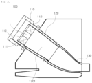
- the plurality of combustors 100 may be arranged in combustor casing having a cell shape to constitute a combustion system of the gas turbine 10, wherein each of the combustors includes a fuel nozzle 110 through which fuel is injected, a liner 120 forming a combustion chamber, a transition piece 130 formed as a connection between the combustor 100 and the turbine section 12.
- the liner 120 provides a combustion space in which fuel injected through the fuel nozzle 110 and compressed air supplied from the compressor 11 are mixed and burned.
- the liner 120 includes a combustion chamber that provides the combustion space in which the fuel mixed with air is burned, and an annular flow path that forms an annular space while surrounding the combustion chamber.
- the fuel nozzle 110 is coupled to the front side of the liner 120 and an igniter is coupled to the sidewall of the liner 120.
- the transition piece 130 is connected to the rear side of the liner so that the combustion gas burned by an ignition plug can be transferred to the turbine side. Similar to the liner 120, the transition piece 130 has an annular flow path surrounding an inner space of the transition piece 130 is formed. As the compressed air flows along the annular flow path, the outer wall of the transition piece 130 is cooled to prevent damage due to high temperature of the combustion gas.
- the high-temperature and high-pressure combustion gas from the combustor 100 is supplied to the turbine section 12 described above.
- the high-temperature and high-pressure combustion gas supplied to the turbine section 12 expands while passing through the inside of the turbine section 12, and accordingly, impulses and reaction forces are applied to the turbine blades, which will be described later, to generate rotational torque.
- the resultant rotational torque is transmitted to the compressor through the above-described torque tube, and an excess of the power required to drive the compressor is used to drive a generator or the like.
- the turbine section 12 is fundamentally similar to the structure of a compressor 11. That is, the turbine section 12 is also provided with a plurality of turbine rotors similar to the compressor rotor of the compressor 11.
- the turbine rotor includes a turbine disk and a plurality of turbine blades radially disposed around the turbine disk.
- the plurality of turbine vanes is also annually arranged, on the basis of the same stage, on the turbine casing between adjacent stages of turbine blades to guide a flow direction of the combustion gas, which passed through the turbine blades.
- the turbine casing and the turbine vanes may be collectively defined as a turbine stator to distinguish them from the turbine rotor.
- a gas turbine combustor 100 includes a hollow nozzle 110, a liner 120, and a transition piece 130.
- the hollow nozzle 110 receives compressed air from the compressor 11 and fuel through a fuel supply (not shown), and produces a mixed fuel (air-fuel mixture).
- the liner 120 is connected to the downstream side of the hollow nozzle 110 with respect to a flow direction of compressed air or combustion gases, and internally forms a combustion chamber 1201 in which the mixed fluid (air-fuel mixture) injected from the hollow nozzle 110 is burned.
- the transition piece 130 is connected to the downstream side of the liner 120, and supplies combustion gases generated in the combustion chamber of the liner 120 to the turbine section 12.
- the hollow nozzle 110 includes a nozzle casing 111 and a plurality of rotary vanes 112, wherein the nozzle casing 111 is preferably formed from a hollow tube having a corresponding diameter.
- the plurality of rotary vanes 112 is arranged radially along an inner surface of an inlet of the nozzle casing 111 through which the compressed air is introduced, forming a hollow center 1 through which the compressed air flows at the center of the nozzle casing 111.
- each of the plurality of rotary vanes 112 is formed to be inclined at a corresponding specified angle as a conventional rotary vane, so that the compressed air passing through the rotary vanes 112 flows while turning.
- each of the plurality of rotary vanes 112 has a first fuel injection hole 113 (illustrated in FIG. 4 ) and a second fuel injection hole 114, wherein the first fuel injection hole 113 is formed on the side facing the center (hollow center: 1) of the nozzle casing 111 in the rotary vanes 112, and ejects a first type of fuel with a relatively low flame propagation speed.
- the first type of fuel is preferably LNG or NG (i.e., liquefied natural gas or natural gas, respectively), and the first fuel injection hole 113 is provided preferably in plural in number such that a plurality of first injection holes is arranged at regular intervals along the longitudinal direction of the side facing the center of the nozzle casing 111.
- LNG or NG i.e., liquefied natural gas or natural gas, respectively
- a second low-speed flow region 30 is generated at an outlet of the length of the nozzle casing 111 as the compressed air passing through the center (hollow center: 1) of the nozzle casing 111 flows, and a flame position can be fixed in the second low-speed flow region 30.
- the second fuel injection hole 114 is formed at an end of the side facing the inlet of the nozzle casing 111 of the rotary vane 112 to eject a second type of fuel having a relatively high flame propagation speed.
- the second fuel is preferably hydrogen
- the second fuel injection hole 114 is provided preferably in plural in number such that a plurality of second fuel injection holes is arranged at regular intervals along the longitudinal direction of the side end facing the inlet of the nozzle casing 111.
- the second type of fuel having a relatively high flame propagation speed generates a first low-speed flow region 20 along the length of the nozzle casing 111, and the flame position can be fixed in the first low-speed flow region 20.
- first low-speed flow region 20 has a larger distribution than the second low-speed flow region 30 as the fuel flows in the form of a vortex in the first low-speed flow region.
- the hollow nozzle, the combustor including the hollow nozzle, and the gas turbine including the combustor according to one embodiment of the present disclosure are capable of simultaneously or selectively using a fuel with a relatively low flame propagation speed and a fuel with a relatively high flame propagation speed, as well as fixing the flame position at a corresponding position depending on the types of fuel, so that the two types of fuel can be stably burned.
Abstract
A hollow nozzle (110) including a tubular nozzle casing (111) and a plurality of rotary vanes (112) arranged radially along an inner surface of an inlet of the nozzle casing, through which compressed air is introduced, forming a hollow center (1) at the center of the nozzle casing through which the compressed air flows, each of the rotary vanes including a first fuel injection hole (113) through which a first type of fuel having a predetermined flame propagation speed is injected toward the hollow center, and a second fuel injection hole (114) through which a second type of fuel having a higher flame propagation speed than the first type of fuel is injected, a combustor including the hollow nozzle, and a gas turbine including the combustor.
Description
- The present application claims priority to
Korean Patent Application No. 10-2022-0079727, filed on June 29, 2022 - The present disclosure relates to a hollow nozzle, a combustor including the hollow nozzle, and a gas turbine including the combustor and, more particularly, to a hollow nozzle in which compressed air supplied from a compressor is mixed with fuel, an air-fuel mixture is combusted, and the resulting combustion gases are supplied to a turbine, a combustor including the hollow nozzle, and a gas turbine including the combustor.
- In general, a turbomachine refers to an apparatus that generates power for power generation through a fluid (particularly, gas) passing through the turbomachine. Therefore, the turbomachine is usually installed and used together with a generator. Such a turbomachine may include a gas turbine, a steam turbine, a wind power turbine, and the like. The gas turbine is an apparatus that mixes compressed air and natural gas and combusts an air-fuel mixture to generate combustion, which in turn generates power for power generation. The steam turbine is an apparatus that heats water to generate steam, which in turn generates power for power generation. The wind turbine is an apparatus that converts wind power into power for power generation.
- Among the turbomachines, the gas turbine includes a compressor, a combustor, and a turbine. The compressor has a plurality of compressor vanes and compressor blades alternately arranged within a compressor casing. In addition, the compressor sucks external air through a compressor inlet scroll strut. The sucked air is compressed by the compressor vanes and the compressor blades while passing through an interior of the compressor. The combustor receives the compressed air from the compressor and mixes the compressed air with fuel to form a fuel-air mixture.
- In addition, the combustor ignites the fuel-air mixture with an igniter to generate high-temperature and high-pressure combustion gas. The generated combustion gas is supplied to the turbine. In the turbine, a plurality of turbine vanes and turbine blades are arranged in a turbine casing. The combustion gas generated by the combustor passes through the turbine. While passing through an interior of the turbine, the combustion gas rotates the turbine blades and then is discharged to the outside through a turbine diffuser.
- Among the turbomachines, the steam turbine includes an evaporator and a turbine. The evaporator heats water supplied from the outside to generate steam. In the turbine, a plurality of turbine vanes and turbine blades are alternately disposed in a turbine casing, similarly to the turbine in a gas turbine. However, in the turbine in the steam turbine, the steam generated in the evaporator, instead of the combustion gas, passes through the turbine to rotate the turbine blades.
- On the other hand, among turbomachines, in the case of a gas turbine, a high temperature flame is generated inside the combustor, so it is necessary to protect a fuel nozzle that injects a mixture of fuel and air into a combustion chamber of the combustor from such a high temperature flame.
- When two types of fuels with different flame propagation speeds are used simultaneously in a turbomachine, the flame position is not uniformly guided due to the difference in flame propagation speeds, and noise and vibration are generated during the combustion process due to incomplete combustion.
- The foregoing is intended merely to aid in the understanding of the background of the present disclosure, and is not intended to mean that the present disclosure falls within the purview of the related art that is already known to those skilled in the art.
- Accordingly, the present disclosure has been made keeping in mind the above problems occurring in the related art, and an objective of the present disclosure is to provide a hollow nozzle capable of simultaneously using both a fuel with a relatively high flame propagation speed and a fuel with a relatively low flame propagation speed and supplying the two types of fuels in a uniformly mixed state, a combustor including the hollow nozzle, and a gas turbine including the combustor.
- According to an aspect of the present disclosure, there is provided a hollow nozzle configured to mix compressed air supplied from a compressor of a gas turbine with fuel supplied from a fuel supply and supply a compressed air-fuel mixture into a liner, the hollow nozzle including: a tubular nozzle casing; and a plurality of rotary vanes arranged radially along an inner surface of an inlet of the nozzle casing, through which compressed air is introduced, forming a hollow center at the center of the nozzle casing through which the compressed air flows, each of the rotary vanes including: a first fuel injection hole through which a first type of fuel having a predetermined flame propagation speed is injected toward the hollow center; and a second fuel injection hole through which a second type of fuel having a higher flame propagation speed than the first type of fuel is injected.
- The first fuel injection hole may be formed on a side facing the center of the nozzle casing of the rotary vane.
- The first fuel injection hole may be provided in plural such that a plurality of first injection holes is arranged at regular intervals along a longitudinal direction of the side facing the center of the nozzle casing.
- The second fuel injector may be formed in a side facing the inlet of the nozzle casing of the rotary vane, wherein the second type of fuel flows along an outer surface of the rotary vane.
- The second fuel injection hole may be provided in plural such that a plurality of second injection holes is arranged at regular intervals along a side facing the inlet of the nozzle casing.
- According to another aspect of the present disclosure, there is provided a combustor configured to mix compressed air supplied from a compressor with fuel, combust a mixed fluid, and supply combustion gases to a turbine section, the combustor including: a hollow nozzle configured to receive and mix the compressed air from the compressor and the fuel through a fuel supply to produce the mixed fluid; a liner connected to the hollow nozzle and forming a combustion chamber in which the mixed fluid produced in the hollow nozzle is combusted; and a transition piece connected to the liner to supply the combustion gases produced in the liner to the turbine section, the hollow nozzle including: a tubular nozzle casing; and a plurality of rotary vanes arranged radially along an inner surface of an inlet of the nozzle casing, through which the compressed air is introduced, forming a hollow center at the center of the nozzle casing through which the compressed air flows, each of the rotary vanes including: a first fuel injection hole through which a first type of fuel having a predetermined flame propagation speed is injected toward the hollow center; and a second fuel injection hole through which a second type of fuel having a higher flame propagation speed than the first type of fuel is injected.
- According to a further aspect of the present disclosure, there is provided a gas turbine including: a compressor configured to compress air supplied from the outside; a turbine section configured to generate power for generating electricity as combustion gases internally pass through the turbine section; and a combustor configured to mix the compressed air supplied from the compressor with fuel, combust a mixed fluid, and supply combustion gases to the turbine section, the combustor including: a hollow nozzle configured to receive and mix the compressed air from the compressor and the fuel through a fuel supply to produce the mixed fluid; a liner connected to the hollow nozzle and forming a combustion chamber in which the mixed fluid produced in the hollow nozzle is combusted; and a transition piece connected to the liner to supply the combustion gases produced in the liner to the turbine section, the hollow nozzle including: a tubular nozzle casing; and a plurality of rotary vanes arranged radially along an inner surface of an inlet of the nozzle casing, through which the compressed air is introduced, forming a hollow center at the center of the nozzle casing through which the compressed air flows, each of the rotary vanes including: a first fuel injection hole through which a first type of fuel having a predetermined flame propagation speed is injected toward the hollow center; and a second fuel injection hole through which a second type of fuel having a higher flame propagation speed than the first type of fuel is injected.
- The effects produced by the hollow nozzle, the combustor including the hollow nozzle, and the gas turbine including the combustor according to the present disclosure are as follows.
- The present disclosure has the effect that a fuel with a relatively high flame propagation speed and a fuel with a relatively low flame propagation speed can both be used at the same time, and can be supplied in a uniformly mixed state.
- The above and other aspects will become more apparent from the following description of the exemplary embodiments with reference to the accompanying drawings, in which:
-
FIG. 1 is a cross-sectional view illustrating a gas turbine according to the present disclosure; -
FIG. 2 is a schematic view illustrating a combustor illustrated inFIG. 1 ; -
FIG. 3 is an exemplary view illustrating a hollow nozzle inlet of a gas turbine combustor according to an embodiment of the present disclosure; -
FIG. 4 is an illustrative view illustrating a hollow nozzle outlet of a gas turbine combustor according to an embodiment of the present disclosure; -
FIG. 5 is an illustrative view illustrating a flame state according to a hollow nozzle of a gas turbine combustor according to an embodiment of the present disclosure; and -
FIG. 6 is an illustrative view illustrating flows of fuel and compressed air through the hollow nozzle of the gas turbine combustor according to an embodiment of the present disclosure. - Hereinafter, preferred embodiments according to the present disclosure will be described in detail with reference to the accompanying drawings. Prior to describing the present disclosure, the terms or words used herein should not be construed as being limited to conventional or dictionary meanings, but may only construed as meanings and concepts consistent with the technical idea of the present disclosure on the basis of the principle that the inventors can properly define the meanings and concepts of the terms in order to best describe his invention.
- Accordingly, embodiments described herein and the configurations illustrated in the drawings are only the most preferred embodiments of the present disclosure and do not represent the entire technical idea of the invention, so it is to be understood that there may be equivalent variations that can be substituted for the embodiments and the configurations.
- The present disclosure is directed to a hollow nozzle, which is capable of simultaneously utilizing two types of fuels with different flame propagation speeds, a combustor including the hollow nozzle, and a gas turbine including the combustor, which will be described with reference to the drawings.
- Referring to
FIG. 1 , agas turbine 10 includes acompressor 11, acombustor 100, and aturbine section 12. In a flow direction of gas (compressed air or combustion gas), thecompressor 11 is disposed on the upstream side of thegas turbine 10, and theturbine section 12 is disposed on the downstream side of the gas turbine. In addition, thecombustor 100 is arranged between thecompressor 11 and theturbine section 12. - The
compressor 11 accommodates, inside a compressor casing, compressor vanes and a compressor rotor including a compressor disk and compressor blades, and theturbine section 12 accommodates, inside a turbine casing, turbine vanes and a turbine rotor including a turbine disk and turbine blades. These compressor vanes and the compressor rotor are arranged in a multi-stage along a flow direction of compressed air, and the turbine vanes and the turbine rotor are also arranged in a multi-stage along a flow direction of combustion gas. - At this time, it is designed such that the
compressor 11 has an internal space of which the volume decreases from the front-stage toward the rear-stage so that the intake air can be compressed, whereas theturbine 12 has an internal space of which the volume increases from the front-stage toward the rear-stage so that the combustion gas supplied from the combustor can expand. - On the other hand, between the compressor rotor located on the rear end side of the
compressor 11 and the turbine rotor located on the front end side of theturbine section 12, a torque tube is disposed as a torque transmission member to transmit the rotational torque generated by theturbine section 12 to thecompressor 11. Although the torque tube may be composed of a plurality of torque tube disks arranged in three stages in total as illustrated inFIG. 1 , this is only one of several embodiments of the present disclosure, so the torque tube may be composed of a plurality of torque tube disks arranged in four or more stages or two or less stages. - The compressor rotor includes a compressor disk and a compressor blade. A plurality of (e.g., 14) compressor disks are provided inside the compressor casing, and the respective compressor disks are fastened so as not to be spaced apart in the axial direction by a tie rod.
- More specifically, the respective compressor disks are aligned along the axial direction with the tie rod passing through the central portion thereof, and adjacent compressor disks are arranged such that the opposing surfaces of the adjacent compressor disks are compressed by the tie rod so that the adjacent compressor disks cannot rotate relative to each other.
- The plurality of compressor blades is radially coupled to an outer circumferential surface of the compressor disk in a multi-stage. Further, the plurality of compressor vanes is arranged in a multi-stage on an inner circumferential surface of the compressor casing such that each stage of compressor vanes is disposed between adjacent stages of compressor blades. Unlike the compressor disk, the compressor vanes maintain a fixed state so as not to rotate, and serve to guide the compressed air, which passed through an upstream-side stage of compressor blades, to a downstream-side stage of compressor blades. Here, the compressor casing and the compressor vanes may be collectively defined as a compressor stator to distinguish them from the compressor rotor.
- The tie rod is arranged to penetrate the center of the plurality of compressor disks and turbine disks, which will be described later, such that one end thereof is fastened in the compressor disk located on the foremost end side of the compressor and the other end thereof is fastened by a fastening nut.
- Since the tie rod may be formed in various structures depending on the gas turbine, the shape of the tie rod is not necessarily limited to the shape illustrated in
FIG. 1 . That is, as illustrated, one tie rod may have a form in which the tie rod passes through the central portion of the compressor disks and the turbine disks, a form in which the plurality of tie rods are arranged in a circumferential manner, or a combination thereof. - Although not illustrated in the drawings, the compressor of the gas turbine may be provided with a deswirler that serves as a guide for increasing a pressure of fluid and adjusting a flow angle of the fluid entering a combustor inlet to a designed flow angle.
- The
combustor 100 serves to mix an incoming compressed air with fuel and combust the air-fuel mixture to produce high-temperature, high-pressure combustion gas with high energy, thereby raising the temperature of the combustion gas up to the heat-resistant limit of the combustor and turbine parts through an isothermal combustion process. - The plurality of
combustors 100 may be arranged in combustor casing having a cell shape to constitute a combustion system of thegas turbine 10, wherein each of the combustors includes afuel nozzle 110 through which fuel is injected, aliner 120 forming a combustion chamber, atransition piece 130 formed as a connection between the combustor 100 and theturbine section 12. - Specifically, the
liner 120 provides a combustion space in which fuel injected through thefuel nozzle 110 and compressed air supplied from thecompressor 11 are mixed and burned. Theliner 120 includes a combustion chamber that provides the combustion space in which the fuel mixed with air is burned, and an annular flow path that forms an annular space while surrounding the combustion chamber. - In addition, the
fuel nozzle 110 is coupled to the front side of theliner 120 and an igniter is coupled to the sidewall of theliner 120. - In the liner annular flow path, compressed air introduced through a plurality of holes provided in an outer wall of the
liner 120 flows, and the compressed air that cooled thetransition piece 130 to be described later also flows. As such, as the compressed air flows along the outer wall of theliner 120, it is possible to prevent theliner 120 from being thermally damaged by heat generated by the combustion of fuel in the combustion chamber. - The
transition piece 130 is connected to the rear side of the liner so that the combustion gas burned by an ignition plug can be transferred to the turbine side. Similar to theliner 120, thetransition piece 130 has an annular flow path surrounding an inner space of thetransition piece 130 is formed. As the compressed air flows along the annular flow path, the outer wall of thetransition piece 130 is cooled to prevent damage due to high temperature of the combustion gas. - Meanwhile, the high-temperature and high-pressure combustion gas from the
combustor 100 is supplied to theturbine section 12 described above. The high-temperature and high-pressure combustion gas supplied to theturbine section 12 expands while passing through the inside of theturbine section 12, and accordingly, impulses and reaction forces are applied to the turbine blades, which will be described later, to generate rotational torque. The resultant rotational torque is transmitted to the compressor through the above-described torque tube, and an excess of the power required to drive the compressor is used to drive a generator or the like. - The
turbine section 12 is fundamentally similar to the structure of acompressor 11. That is, theturbine section 12 is also provided with a plurality of turbine rotors similar to the compressor rotor of thecompressor 11. Thus, the turbine rotor includes a turbine disk and a plurality of turbine blades radially disposed around the turbine disk. The plurality of turbine vanes is also annually arranged, on the basis of the same stage, on the turbine casing between adjacent stages of turbine blades to guide a flow direction of the combustion gas, which passed through the turbine blades. Here, the turbine casing and the turbine vanes may be collectively defined as a turbine stator to distinguish them from the turbine rotor. - Referring to
FIGS. 2 to 6 , agas turbine combustor 100 according to one embodiment of the present disclosure includes ahollow nozzle 110, aliner 120, and atransition piece 130. - First, the
hollow nozzle 110 receives compressed air from thecompressor 11 and fuel through a fuel supply (not shown), and produces a mixed fuel (air-fuel mixture). - The
liner 120 is connected to the downstream side of thehollow nozzle 110 with respect to a flow direction of compressed air or combustion gases, and internally forms acombustion chamber 1201 in which the mixed fluid (air-fuel mixture) injected from thehollow nozzle 110 is burned. - The
transition piece 130 is connected to the downstream side of theliner 120, and supplies combustion gases generated in the combustion chamber of theliner 120 to theturbine section 12. - In addition, the
hollow nozzle 110 includes anozzle casing 111 and a plurality ofrotary vanes 112, wherein thenozzle casing 111 is preferably formed from a hollow tube having a corresponding diameter. - The plurality of
rotary vanes 112 is arranged radially along an inner surface of an inlet of thenozzle casing 111 through which the compressed air is introduced, forming ahollow center 1 through which the compressed air flows at the center of thenozzle casing 111. - At this time, each of the plurality of
rotary vanes 112 is formed to be inclined at a corresponding specified angle as a conventional rotary vane, so that the compressed air passing through therotary vanes 112 flows while turning. - Thus, a portion of the compressed air introduced through the inlet of the
nozzle casing 111 through thehollow center 1 formed in the center of thenozzle casing 111 immediately flows along the longitudinal direction of thenozzle casing 111, and a portion of the compressed air flows while turning along the longitudinal direction of thenozzle casing 111 due to the plurality ofrotary vanes 112. - In addition, each of the plurality of
rotary vanes 112 has a first fuel injection hole 113 (illustrated inFIG. 4 ) and a secondfuel injection hole 114, wherein the firstfuel injection hole 113 is formed on the side facing the center (hollow center: 1) of thenozzle casing 111 in therotary vanes 112, and ejects a first type of fuel with a relatively low flame propagation speed. - In this case, the first type of fuel is preferably LNG or NG (i.e., liquefied natural gas or natural gas, respectively), and the first
fuel injection hole 113 is provided preferably in plural in number such that a plurality of first injection holes is arranged at regular intervals along the longitudinal direction of the side facing the center of thenozzle casing 111. - Thus, when the first type of fuel and compressed air are mixed and burned, a second low-
speed flow region 30 is generated at an outlet of the length of thenozzle casing 111 as the compressed air passing through the center (hollow center: 1) of thenozzle casing 111 flows, and a flame position can be fixed in the second low-speed flow region 30. - Furthermore, the second
fuel injection hole 114 is formed at an end of the side facing the inlet of thenozzle casing 111 of therotary vane 112 to eject a second type of fuel having a relatively high flame propagation speed. - In this case, the second fuel is preferably hydrogen, and the second
fuel injection hole 114 is provided preferably in plural in number such that a plurality of second fuel injection holes is arranged at regular intervals along the longitudinal direction of the side end facing the inlet of thenozzle casing 111. - Thus, the second type of fuel with a relatively high flame propagation speed ejected through the second fuel injection holes 114, together with the compressed air, flows in the form of a vortex while turning along the inner surface of the
nozzle casing 111 along therotary vanes 112, and is guided from the inlet to the outlet of thenozzle casing 111. - Here, the second type of fuel having a relatively high flame propagation speed generates a first low-
speed flow region 20 along the length of thenozzle casing 111, and the flame position can be fixed in the first low-speed flow region 20. - In addition, the first low-
speed flow region 20 has a larger distribution than the second low-speed flow region 30 as the fuel flows in the form of a vortex in the first low-speed flow region. - Therefore, the hollow nozzle, the combustor including the hollow nozzle, and the gas turbine including the combustor according to one embodiment of the present disclosure are capable of simultaneously or selectively using a fuel with a relatively low flame propagation speed and a fuel with a relatively high flame propagation speed, as well as fixing the flame position at a corresponding position depending on the types of fuel, so that the two types of fuel can be stably burned.
- Although the present disclosure has been described with reference to the embodiments illustrated in the drawings, the described embodiments are merely illustrative, so those skilled in the art will understand that various modifications and equivalents thereof can be made therefrom. Therefore, the true technical scope of the present disclosure should be determined by the technical spirit of the appended claims.
Claims (15)
- A hollow nozzle (110) configured to mix compressed air supplied from a compressor (11) of a gas turbine (10) with fuel supplied from a fuel supply and supply a compressed air-fuel mixture into a liner (120), the hollow nozzle (110) comprising:a tubular nozzle casing (111); anda plurality of rotary vanes (112) arranged radially along an inner surface of an inlet of the nozzle casing (111), through which compressed air is introduced, forming a hollow center (1) at the center of the nozzle casing (111) through which the compressed air flows, each of the rotary vanes (112) comprising:a first fuel injection hole (113) through which a first type of fuel having a predetermined flame propagation speed is injected toward the hollow center (1); anda second fuel injection hole (114) through which a second type of fuel having a higher flame propagation speed than the first type of fuel is injected.
- The hollow nozzle (110) according to claim 1, wherein the first fuel injection hole (113) is provided on a side of the rotary vane (112) facing the center of the nozzle casing (111).
- The hollow nozzle (110) according to any one of the preceding claims, wherein the first fuel injection hole (113) is provided in plural such that a plurality of first injection holes is arranged at regular intervals along a longitudinal direction of the side of the rotary vane (112) facing the center of the nozzle casing (111).
- The hollow nozzle (110) according to any one of the preceding claims, wherein the second fuel injector is provided in a side of the rotary vane (112) facing the inlet of the nozzle casing (111), wherein the second type of fuel flows along an outer surface of the rotary vane (112).
- The hollow nozzle (110) according to any one of the preceding claims, wherein the second fuel injection hole (114) is provided in plural such that a plurality of second injection holes is arranged at regular intervals along a side of the rotary vane (112) facing the inlet of the nozzle casing (111).
- A combustor (100) configured to mix compressed air supplied from a compressor (11) with fuel, combust a mixed fluid, and supply combustion gases to a turbine section (12), the combustor (100) comprising:a hollow nozzle (110) configured to receive and mix the compressed air from the compressor (11) and the fuel through a fuel supply to produce the mixed fluid;a liner (120) connected to the hollow nozzle (110) and forming a combustion chamber (1201) in which the mixed fluid produced in the hollow nozzle (110) is combusted; anda transition piece (130) connected to the liner (120) to supply the combustion gases produced in the liner (120) to the turbine section (12), the hollow nozzle (110) comprising:a tubular nozzle casing (111); anda plurality of rotary vanes (112) arranged radially along an inner surface of an inlet of the nozzle casing (111), through which the compressed air is introduced, forming a hollow center (1) at the center of the nozzle casing (111) through which the compressed air flows, each of the rotary vanes (112) comprising:a first fuel injection hole (113) through which a first type of fuel having a predetermined flame propagation speed is injected toward the hollow center (1); anda second fuel injection hole (114) through which a second type of fuel having a higher flame propagation speed than the first type of fuel is injected.
- The combustor (100) according to claim 6, wherein the first fuel injection hole (113) is provided on a side of the rotary vane (112) facing the center of the nozzle casing (111).
- The combustor (100) according to any one of claims 6 to 7, wherein the first fuel injection hole (113) is provided in plural such that a plurality of first injection holes is arranged at regular intervals along a longitudinal direction of the side of the rotary vane (112) facing the center of the nozzle casing (111).
- The combustor (100) according to any one of claims 6 to 8, wherein the second fuel injector is provided in a side of the rotary vane (112) facing the inlet of the nozzle casing (111), wherein the second type of fuel flows along an outer surface of the rotary vane (112).
- The combustor (100) according to any one of claims 6 to 9, wherein the second fuel injection hole (114) is provided in plural such that a plurality of second injection holes is arranged at regular intervals along a side of the rotary vane (112) facing the inlet of the nozzle casing (111).
- A gas turbine (10) comprising:a compressor (11) configured to compress air supplied from the outside;a turbine section (12) configured to generate power for generating electricity as combustion gases internally pass through the turbine section; anda combustor (100) configured to mix the compressed air supplied from the compressor with fuel, combust a mixed fluid, and supply combustion gases to the turbine section (12), the combustor (100) comprising:a hollow nozzle (110) configured to receive and mix the compressed air from the compressor (11) and the fuel through a fuel supply to produce the mixed fluid;a liner (120) connected to the hollow nozzle (110) and forming a combustion chamber (1201) in which the mixed fluid produced in the hollow nozzle (110) is combusted; anda transition piece (130) connected to the liner (120) to supply the combustion gases produced in the liner (120) to the turbine section (12), the hollow nozzle (110) comprising:a tubular nozzle casing (111); anda plurality of rotary vanes (112) arranged radially along an inner surface of an inlet of the nozzle casing (111), through which the compressed air is introduced, forming a hollow center (1) at the center of the nozzle casing (111) through which the compressed air flows, each of the rotary vanes (112) comprising:a first fuel injection hole (113) through which a first type of fuel having a predetermined flame propagation speed is injected toward the hollow center (1); anda second fuel injection hole (114) through which a second type of fuel having a higher flame propagation speed than the first type of fuel is injected.
- The gas turbine (10) according to claim 11, wherein the first fuel injection hole (113) is provided on a side of the rotary vane (112) facing the center of the nozzle casing (111).
- The gas turbine (10) according to any one of claims 11 to 12, wherein the first fuel injection hole (113) is provided in plural such that a plurality of first injection holes is arranged at regular intervals along a longitudinal direction of the side of the rotary vane (112) facing the center of the nozzle casing (111).
- The gas turbine 10 according to any one of claims 11 to 13, wherein the second fuel injector is provided in a side of the rotary vane (112) facing the inlet of the nozzle casing (111), wherein the second type of fuel flows along an outer surface of the rotary vane (112).
- The gas turbine 10 according to any one of claims 11 to 14, wherein the second fuel injection hole (114) is provided in plural such that a plurality of second injection holes is arranged at regular intervals along a side of the rotary vane (112) facing the inlet of the nozzle casing (111).
Applications Claiming Priority (1)
| Application Number | Priority Date | Filing Date | Title |
|---|---|---|---|
| KR1020220079727A KR20240002481A (en) | 2022-06-29 | 2022-06-29 | Hollow nozzle and combustor including the hollow nozzle, and gas turbine including the combustor |
Publications (1)
| Publication Number | Publication Date |
|---|---|
| EP4299984A1 true EP4299984A1 (en) | 2024-01-03 |
Family
ID=87060543
Family Applications (1)
| Application Number | Title | Priority Date | Filing Date |
|---|---|---|---|
| EP23182388.1A Pending EP4299984A1 (en) | 2022-06-29 | 2023-06-29 | Hollow nozzle, combustor including hollow nozzle, and gas turbine including combustor |
Country Status (3)
| Country | Link |
|---|---|
| US (1) | US20240003538A1 (en) |
| EP (1) | EP4299984A1 (en) |
| KR (1) | KR20240002481A (en) |
Citations (4)
| Publication number | Priority date | Publication date | Assignee | Title |
|---|---|---|---|---|
| US20080078183A1 (en) * | 2006-10-03 | 2008-04-03 | General Electric Company | Liquid fuel enhancement for natural gas swirl stabilized nozzle and method |
| EP2161502A1 (en) * | 2008-09-05 | 2010-03-10 | Siemens Aktiengesellschaft | Pre-mix burner for a low calorie and high calorie fuel |
| CN204438189U (en) * | 2014-12-30 | 2015-07-01 | 北京华清燃气轮机与煤气化联合循环工程技术有限公司 | A kind of dual fuel nozzle of gas-turbine combustion chamber |
| US20190086090A1 (en) * | 2016-04-22 | 2019-03-21 | Siemens Aktiengesellschaft | Swirler for mixing fuel with air in a combustion engine |
Family Cites Families (1)
| Publication number | Priority date | Publication date | Assignee | Title |
|---|---|---|---|---|
| KR102116903B1 (en) * | 2014-12-12 | 2020-05-29 | 한화에어로스페이스 주식회사 | Swirler assembly |
-
2022
- 2022-06-29 KR KR1020220079727A patent/KR20240002481A/en active IP Right Grant
-
2023
- 2023-06-29 US US18/216,397 patent/US20240003538A1/en active Pending
- 2023-06-29 EP EP23182388.1A patent/EP4299984A1/en active Pending
Patent Citations (4)
| Publication number | Priority date | Publication date | Assignee | Title |
|---|---|---|---|---|
| US20080078183A1 (en) * | 2006-10-03 | 2008-04-03 | General Electric Company | Liquid fuel enhancement for natural gas swirl stabilized nozzle and method |
| EP2161502A1 (en) * | 2008-09-05 | 2010-03-10 | Siemens Aktiengesellschaft | Pre-mix burner for a low calorie and high calorie fuel |
| CN204438189U (en) * | 2014-12-30 | 2015-07-01 | 北京华清燃气轮机与煤气化联合循环工程技术有限公司 | A kind of dual fuel nozzle of gas-turbine combustion chamber |
| US20190086090A1 (en) * | 2016-04-22 | 2019-03-21 | Siemens Aktiengesellschaft | Swirler for mixing fuel with air in a combustion engine |
Also Published As
| Publication number | Publication date |
|---|---|
| US20240003538A1 (en) | 2024-01-04 |
| KR20240002481A (en) | 2024-01-05 |
Similar Documents
| Publication | Publication Date | Title |
|---|---|---|
| KR102126882B1 (en) | Nozzle assembly, combustor and gas turbine including the same | |
| CN109028144B (en) | Integral vortex rotary detonation propulsion system | |
| KR102437977B1 (en) | Nozzle assembly, Combustor and Gas turbine comprising the same | |
| KR102164618B1 (en) | Swirler having fuel manifold, and a combustor and a gas turbine including the same | |
| EP4299984A1 (en) | Hollow nozzle, combustor including hollow nozzle, and gas turbine including combustor | |
| KR102126883B1 (en) | Nozzle assembly, combustor and gas turbine including the same | |
| US20240003545A1 (en) | Jet nozzle, combustor, and gas turbine including same | |
| KR102433706B1 (en) | Nozzle assembly, Combustor and Gas turbine comprising the same | |
| KR102437976B1 (en) | Nozzle assembly, Combustor and Gas turbine comprising the same | |
| KR102437978B1 (en) | Nozzle assembly, combustor and gas turbine comprising the same | |
| US20240003546A1 (en) | Jet nozzle, combustor, and gas turbine including same | |
| KR102472389B1 (en) | Nozzle assembly, combustor and gas turbine comprising the same | |
| US20240003544A1 (en) | Jet nozzle, combustor, and gas turbine including same | |
| US11846424B2 (en) | Injection nozzle, combustor including same nozzle, and gas turbine including same combustor | |
| KR102426622B1 (en) | Combustor and gas turbine comprising the same | |
| US11542871B2 (en) | Injection nozzle, combustor including same, and gas turbine including same | |
| KR102154221B1 (en) | Combustor and gas turbine including fuel injection member of fuel turning injection type | |
| US11846427B2 (en) | Gas turbine combustor with fuel nozzles shaped with a diameter decreasing and increasing toward a rear side thereof | |
| KR102651451B1 (en) | Gas turbine combustor and gas turbine having same | |
| US20230096973A1 (en) | Sealing assembly and turbomachine including same | |
| KR102415841B1 (en) | Discharge-nozzle, Combustor and Gas turbine comprising the same | |
| KR102153014B1 (en) | Combuster and gas turbine having the same | |
| US20220268174A1 (en) | Ring segment and turbomachine including same | |
| KR20190036205A (en) | Gas Turbine |
Legal Events
| Date | Code | Title | Description |
|---|---|---|---|
| PUAI | Public reference made under article 153(3) epc to a published international application that has entered the european phase |
Free format text: ORIGINAL CODE: 0009012 |
|
| STAA | Information on the status of an ep patent application or granted ep patent |
Free format text: STATUS: REQUEST FOR EXAMINATION WAS MADE |
|
| 17P | Request for examination filed |
Effective date: 20230629 |
|
| AK | Designated contracting states |
Kind code of ref document: A1 Designated state(s): AL AT BE BG CH CY CZ DE DK EE ES FI FR GB GR HR HU IE IS IT LI LT LU LV MC ME MK MT NL NO PL PT RO RS SE SI SK SM TR |
|
| RBV | Designated contracting states (corrected) |
Designated state(s): AL AT BE BG CH CY CZ DE DK EE ES FI FR GB GR HR HU IE IS IT LI LT LU LV MC ME MK MT NL NO PL PT RO RS SE SI SK SM TR |