EP4299895A1 - Fuel injection unit - Google Patents
Fuel injection unit Download PDFInfo
- Publication number
- EP4299895A1 EP4299895A1 EP23181890.7A EP23181890A EP4299895A1 EP 4299895 A1 EP4299895 A1 EP 4299895A1 EP 23181890 A EP23181890 A EP 23181890A EP 4299895 A1 EP4299895 A1 EP 4299895A1
- Authority
- EP
- European Patent Office
- Prior art keywords
- injection unit
- injectors
- unit body
- range
- interior channel
- Prior art date
- Legal status (The legal status is an assumption and is not a legal conclusion. Google has not performed a legal analysis and makes no representation as to the accuracy of the status listed.)
- Pending
Links
Images


Classifications
-
- F—MECHANICAL ENGINEERING; LIGHTING; HEATING; WEAPONS; BLASTING
- F02—COMBUSTION ENGINES; HOT-GAS OR COMBUSTION-PRODUCT ENGINE PLANTS
- F02M—SUPPLYING COMBUSTION ENGINES IN GENERAL WITH COMBUSTIBLE MIXTURES OR CONSTITUENTS THEREOF
- F02M57/00—Fuel-injectors combined or associated with other devices
- F02M57/04—Fuel-injectors combined or associated with other devices the devices being combustion-air intake or exhaust valves
-
- F—MECHANICAL ENGINEERING; LIGHTING; HEATING; WEAPONS; BLASTING
- F02—COMBUSTION ENGINES; HOT-GAS OR COMBUSTION-PRODUCT ENGINE PLANTS
- F02M—SUPPLYING COMBUSTION ENGINES IN GENERAL WITH COMBUSTIBLE MIXTURES OR CONSTITUENTS THEREOF
- F02M35/00—Combustion-air cleaners, air intakes, intake silencers, or induction systems specially adapted for, or arranged on, internal-combustion engines
- F02M35/10—Air intakes; Induction systems
- F02M35/10209—Fluid connections to the air intake system; their arrangement of pipes, valves or the like
- F02M35/10216—Fuel injectors; Fuel pipes or rails; Fuel pumps or pressure regulators
-
- F—MECHANICAL ENGINEERING; LIGHTING; HEATING; WEAPONS; BLASTING
- F02—COMBUSTION ENGINES; HOT-GAS OR COMBUSTION-PRODUCT ENGINE PLANTS
- F02M—SUPPLYING COMBUSTION ENGINES IN GENERAL WITH COMBUSTIBLE MIXTURES OR CONSTITUENTS THEREOF
- F02M39/00—Arrangements of fuel-injection apparatus with respect to engines; Pump drives adapted to such arrangements
- F02M39/005—Arrangements of fuel feed-pumps with respect to fuel injection apparatus
-
- F—MECHANICAL ENGINEERING; LIGHTING; HEATING; WEAPONS; BLASTING
- F02—COMBUSTION ENGINES; HOT-GAS OR COMBUSTION-PRODUCT ENGINE PLANTS
- F02M—SUPPLYING COMBUSTION ENGINES IN GENERAL WITH COMBUSTIBLE MIXTURES OR CONSTITUENTS THEREOF
- F02M51/00—Fuel-injection apparatus characterised by being operated electrically
-
- F—MECHANICAL ENGINEERING; LIGHTING; HEATING; WEAPONS; BLASTING
- F02—COMBUSTION ENGINES; HOT-GAS OR COMBUSTION-PRODUCT ENGINE PLANTS
- F02M—SUPPLYING COMBUSTION ENGINES IN GENERAL WITH COMBUSTIBLE MIXTURES OR CONSTITUENTS THEREOF
- F02M69/00—Low-pressure fuel-injection apparatus ; Apparatus with both continuous and intermittent injection; Apparatus injecting different types of fuel
- F02M69/04—Injectors peculiar thereto
- F02M69/042—Positioning of injectors with respect to engine, e.g. in the air intake conduit
- F02M69/044—Positioning of injectors with respect to engine, e.g. in the air intake conduit for injecting into the intake conduit downstream of an air throttle valve
-
- F—MECHANICAL ENGINEERING; LIGHTING; HEATING; WEAPONS; BLASTING
- F02—COMBUSTION ENGINES; HOT-GAS OR COMBUSTION-PRODUCT ENGINE PLANTS
- F02D—CONTROLLING COMBUSTION ENGINES
- F02D9/00—Controlling engines by throttling air or fuel-and-air induction conduits or exhaust conduits
- F02D9/02—Controlling engines by throttling air or fuel-and-air induction conduits or exhaust conduits concerning induction conduits
- F02D2009/0201—Arrangements; Control features; Details thereof
- F02D2009/0208—Arrangements; Control features; Details thereof for small engines
-
- F—MECHANICAL ENGINEERING; LIGHTING; HEATING; WEAPONS; BLASTING
- F02—COMBUSTION ENGINES; HOT-GAS OR COMBUSTION-PRODUCT ENGINE PLANTS
- F02D—CONTROLLING COMBUSTION ENGINES
- F02D9/00—Controlling engines by throttling air or fuel-and-air induction conduits or exhaust conduits
- F02D9/02—Controlling engines by throttling air or fuel-and-air induction conduits or exhaust conduits concerning induction conduits
- F02D2009/0201—Arrangements; Control features; Details thereof
- F02D2009/0225—Intake air or mixture temperature
-
- F—MECHANICAL ENGINEERING; LIGHTING; HEATING; WEAPONS; BLASTING
- F02—COMBUSTION ENGINES; HOT-GAS OR COMBUSTION-PRODUCT ENGINE PLANTS
- F02D—CONTROLLING COMBUSTION ENGINES
- F02D9/00—Controlling engines by throttling air or fuel-and-air induction conduits or exhaust conduits
- F02D9/02—Controlling engines by throttling air or fuel-and-air induction conduits or exhaust conduits concerning induction conduits
- F02D2009/0201—Arrangements; Control features; Details thereof
- F02D2009/0228—Manifold pressure
-
- F—MECHANICAL ENGINEERING; LIGHTING; HEATING; WEAPONS; BLASTING
- F02—COMBUSTION ENGINES; HOT-GAS OR COMBUSTION-PRODUCT ENGINE PLANTS
- F02D—CONTROLLING COMBUSTION ENGINES
- F02D41/00—Electrical control of supply of combustible mixture or its constituents
- F02D41/30—Controlling fuel injection
- F02D41/3094—Controlling fuel injection the fuel injection being effected by at least two different injectors, e.g. one in the intake manifold and one in the cylinder
-
- F—MECHANICAL ENGINEERING; LIGHTING; HEATING; WEAPONS; BLASTING
- F02—COMBUSTION ENGINES; HOT-GAS OR COMBUSTION-PRODUCT ENGINE PLANTS
- F02M—SUPPLYING COMBUSTION ENGINES IN GENERAL WITH COMBUSTIBLE MIXTURES OR CONSTITUENTS THEREOF
- F02M2200/00—Details of fuel-injection apparatus, not otherwise provided for
- F02M2200/24—Fuel-injection apparatus with sensors
-
- F—MECHANICAL ENGINEERING; LIGHTING; HEATING; WEAPONS; BLASTING
- F02—COMBUSTION ENGINES; HOT-GAS OR COMBUSTION-PRODUCT ENGINE PLANTS
- F02M—SUPPLYING COMBUSTION ENGINES IN GENERAL WITH COMBUSTIBLE MIXTURES OR CONSTITUENTS THEREOF
- F02M2200/00—Details of fuel-injection apparatus, not otherwise provided for
- F02M2200/24—Fuel-injection apparatus with sensors
- F02M2200/247—Pressure sensors
-
- F—MECHANICAL ENGINEERING; LIGHTING; HEATING; WEAPONS; BLASTING
- F02—COMBUSTION ENGINES; HOT-GAS OR COMBUSTION-PRODUCT ENGINE PLANTS
- F02M—SUPPLYING COMBUSTION ENGINES IN GENERAL WITH COMBUSTIBLE MIXTURES OR CONSTITUENTS THEREOF
- F02M2200/00—Details of fuel-injection apparatus, not otherwise provided for
- F02M2200/24—Fuel-injection apparatus with sensors
- F02M2200/248—Temperature sensors
Definitions
- the invention relates to fuel injection for a two-stroke combustion engine.
- a two-stroke engine for karts must be reliably supplied with an igniting mixture of gasoline and air in a required quantity and with a required air-to-gasoline ratio depending on the engine load and its rotation speed.
- a carburetor which is, however, considered to be an imprecise device, with which a number of complications is connected, mainly in terms of maintenance, tuning, and high demands for specific experience in its use.
- the proposed solution represents a more accurate and easier-to-operate device able to control the fuel injection electronically. In comparison to a carburetor, this allows for a higher engine operation efficiency with lower emissions and lower fuel consumption.
- the injection unit is placed directly onto the engine block so that the injection unit body is fixed via a flange of a reed valve directly into the intake channel of the cylinder.
- An air filter is mounted on the opposite side of the injection unit body.
- the whole system comprises 2 fuel injector pieces, also a control unit, which sends out electronic impulses to the injectors after an analysis of data from sensors - an air pressure and temperature sensor, a throttle opening sensor, a crank position sensor for determining current engine rotation speed, sensor for water temperature measurement.
- the fuel supply to the injectors is provided using a gasoline pump and regulated by means of a fuel pressure regulation sensor. All electrical components are connected via a cable harness.
- the proposed solution is unique in terms of the shape and location of the two injectors and the air pressure and temperature sensor in the injection unit body so that the injectors are activated efficiently, according to the needs of the engine based on the current rotation speed.
- An injection unit for fuel injection comprises an injection unit body 1.
- the injection unit body 1 includes an interior channel, wherein two injectors 2 for fuel injection into the interior channel of the injection unit body 1 lead into the injection unit body 1.
- a throttle 3 is arranged in the interior channel, the throttle 3 being controllable by a gas acceleration regulation system 4 for regulating flow of the mixture into a combustion chamber.
- An air temperature and pressure sensor for measuring pressure conditions and temperature is in the injection unit body 1.
- the interior channel is positioned along the axis of the injection unit body 1 and it has a shape where, in the upstream direction, it has a constant diameter, then follows a narrowing of the channel in the range of 5° - 30° and then a radius R of 35-45 mm, to provide a correct linear flow in this channel.
- the pressure and temperature sensor is positioned with an angle in the range of 55° -85° relative to the axis of the injection unit body 1.
- a carburetor installation space is identical to the injection unit installation space.
- the injection unit body 1 is made from an aluminium alloy.
- the principle of suction of the mixture into the combustion chamber is the same as for any two-stroke engines for karts.
- an amount of mixture corresponding to the required performance is delivered into the combustion chamber.
- the cadence of opening and the amount of the mixture is determined by the control unit based on an analysis of data from the sensors.
- the flow of the mixture into the combustion chamber is further regulated by closing and opening the throttle 3, which is controlled via an acceleration regulation system 4.
- the throttle is used in engines with a carburetor as well as with fuel injection.
- the position of the two pieces of injectors 2 and the position of the sensors placed in the injection unit body 2 is angularly (or even also dimensionally) dependent on each other. These specific positioning angles ensure the proper functioning of the injection unit. During the process, pressure and negative pressure waves are formed within the unit and due to the arrangement, the proper functioning and subsequent data analysis in the control unit can be ensured.
- the interior shape of the injection unit body channel, which also influences the pressure changes, is also important for the proper functioning of the unit.
- the control unit provides electrical impulses to the injectors, which supply the fuel mixture to the unit.
- the cadence of these impulses is dependent on the engine speed.
- the correctness of the impulse cadence during a speed change is provided using a pre-set data analysis map, which is based on empirical development.
- the principle that is the subject of the invention can be used for any two-stroke engines.
Landscapes
- Engineering & Computer Science (AREA)
- Chemical & Material Sciences (AREA)
- Combustion & Propulsion (AREA)
- Mechanical Engineering (AREA)
- General Engineering & Computer Science (AREA)
- Electrical Control Of Air Or Fuel Supplied To Internal-Combustion Engine (AREA)
Abstract
Description
- The invention relates to fuel injection for a two-stroke combustion engine.
- A two-stroke engine for karts must be reliably supplied with an igniting mixture of gasoline and air in a required quantity and with a required air-to-gasoline ratio depending on the engine load and its rotation speed. Currently, this is ensured by a carburetor, which is, however, considered to be an imprecise device, with which a number of complications is connected, mainly in terms of maintenance, tuning, and high demands for specific experience in its use.
- The defects of the current state of the art are eliminated by an injection unit for fuel injection defined in
claim 1. - The proposed solution represents a more accurate and easier-to-operate device able to control the fuel injection electronically. In comparison to a carburetor, this allows for a higher engine operation efficiency with lower emissions and lower fuel consumption.
- The injection unit is placed directly onto the engine block so that the injection unit body is fixed via a flange of a reed valve directly into the intake channel of the cylinder. An air filter is mounted on the opposite side of the injection unit body.
- Apart from the injection unit itself, a number of components, which are interdependent to a large extent, are also a part of the fuel injection unit. The whole system comprises 2 fuel injector pieces, also a control unit, which sends out electronic impulses to the injectors after an analysis of data from sensors - an air pressure and temperature sensor, a throttle opening sensor, a crank position sensor for determining current engine rotation speed, sensor for water temperature measurement. The fuel supply to the injectors is provided using a gasoline pump and regulated by means of a fuel pressure regulation sensor. All electrical components are connected via a cable harness.
- The proposed solution is unique in terms of the shape and location of the two injectors and the air pressure and temperature sensor in the injection unit body so that the injectors are activated efficiently, according to the needs of the engine based on the current rotation speed.
-
-
Fig. 1 illustrates assembly comprising an injection unit with two injectors, a throttle, an acceleration regulation system, and sensors. -
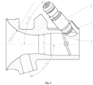
Fig. 2 illustrates a cross section of an injection unit body showing the position of the injector relative to the throttle, the shape of the interior channel, and the axis of the injection unit body. -
Fig. 3 schematically illustrates a cross section of both injectors, where the position of the injectors is determined by a V-shape. - An injection unit for fuel injection comprises an
injection unit body 1. Theinjection unit body 1 includes an interior channel, wherein twoinjectors 2 for fuel injection into the interior channel of theinjection unit body 1 lead into theinjection unit body 1. Athrottle 3 is arranged in the interior channel, thethrottle 3 being controllable by a gasacceleration regulation system 4 for regulating flow of the mixture into a combustion chamber. An air temperature and pressure sensor for measuring pressure conditions and temperature is in theinjection unit body 1. - The interior channel is positioned along the axis of the
injection unit body 1 and it has a shape where, in the upstream direction, it has a constant diameter, then follows a narrowing of the channel in the range of 5° - 30° and then a radius R of 35-45 mm, to provide a correct linear flow in this channel. - The
injectors 2 are placed relative to each other in a position, which is determined by a V-shape and forms a mutual angle in the range of 30° - 70° and forms an angle relative to the channel axis of theinjection unit body 1 in the range of 30°-65°. - The pressure and temperature sensor is positioned with an angle in the range of 55° -85° relative to the axis of the
injection unit body 1. - A carburetor installation space is identical to the injection unit installation space. The
injection unit body 1 is made from an aluminium alloy. - The principle of suction of the mixture into the combustion chamber is the same as for any two-stroke engines for karts. During the intake stroke, an amount of mixture corresponding to the required performance is delivered into the combustion chamber. The cadence of opening and the amount of the mixture is determined by the control unit based on an analysis of data from the sensors. The flow of the mixture into the combustion chamber is further regulated by closing and opening the
throttle 3, which is controlled via anacceleration regulation system 4. The throttle is used in engines with a carburetor as well as with fuel injection. - The position of the two pieces of
injectors 2 and the position of the sensors placed in theinjection unit body 2 is angularly (or even also dimensionally) dependent on each other. These specific positioning angles ensure the proper functioning of the injection unit. During the process, pressure and negative pressure waves are formed within the unit and due to the arrangement, the proper functioning and subsequent data analysis in the control unit can be ensured. The interior shape of the injection unit body channel, which also influences the pressure changes, is also important for the proper functioning of the unit. - The control unit provides electrical impulses to the injectors, which supply the fuel mixture to the unit. The cadence of these impulses is dependent on the engine speed. The correctness of the impulse cadence during a speed change is provided using a pre-set data analysis map, which is based on empirical development.
- The principle that is the subject of the invention can be used for any two-stroke engines.
Claims (5)
- Injection unit for fuel injection, characterized in that it comprises an injection unit body (1) includingan interior channel, wherein two injectors (2) for injecting fuel into the interior channel of the injection unit body (1) are placed in the injection unit body (1),a throttle (3) connectable to an acceleration regulation system (4) for regulating flow of the mixture into combustion chamber, andair temperature and pressure sensor for measuring temperature and pressure conditions.
- Injection unit according to claim 1, characterized in that mutual position of the injectors relative to each other forms a V-shape including an angle in the range of 30° - 70° and the injectors include an angle with the channel axis of the injection unit body (1) in the range of 30°-65°.
- Injection unit according to claim 1 or 2, characterized in that the position of the temperature and pressure sensor includes with the axis of the injection unit body (1) an angle in the range of 55° - 85°.
- Injection unit according to claim 1 or 2 or 3, characterized in that the interior channel is arranged along the axis of the injection unit body (1) and has such a shape, that a part of the interior channel has a constant diameter, following this part of the interior channel is a cone-shaped channel narrowing with an apex angle in the range of 5° to 30° and then follows a radius (R) in the range of 35 to 45 mm.
- Injection unit according to any of the preceding claims, characterized in that a control unit providing electronic impulses for opening the injectors has a preset map for analysis of data from the sensors of pressure, temperature, engine rotation speed, and throttle (3) position, via using coefficients, for a precise time cadence of opening the injectors and thus a precise determination of the amount of mixture injected.
Applications Claiming Priority (1)
| Application Number | Priority Date | Filing Date | Title |
|---|---|---|---|
| CZ2022-40040U CZ36516U1 (en) | 2022-06-27 | 2022-06-27 | Fuel injection equipment |
Publications (1)
| Publication Number | Publication Date |
|---|---|
| EP4299895A1 true EP4299895A1 (en) | 2024-01-03 |
Family
ID=83997739
Family Applications (1)
| Application Number | Title | Priority Date | Filing Date |
|---|---|---|---|
| EP23181890.7A Pending EP4299895A1 (en) | 2022-06-27 | 2023-06-27 | Fuel injection unit |
Country Status (2)
| Country | Link |
|---|---|
| EP (1) | EP4299895A1 (en) |
| CZ (1) | CZ36516U1 (en) |
Citations (4)
| Publication number | Priority date | Publication date | Assignee | Title |
|---|---|---|---|---|
| US4216753A (en) * | 1977-12-14 | 1980-08-12 | Yoyota Jidosha Kogyo Kabushiki Kaisha | Fuel air mixture supply system for use in fuel-injection-type internal combustion engine |
| DE2928350A1 (en) * | 1979-07-13 | 1981-02-05 | Volkswagenwerk Ag | Mixture-compressing IC engine fuel-injection system - has intermittently operating nozzles cut in successively dependent on air flow |
| JPH11294306A (en) * | 1998-04-15 | 1999-10-26 | Suzuki Motor Corp | Fuel injection device |
| CN216811991U (en) * | 2022-01-14 | 2022-06-24 | 上海峰飞航空科技有限公司 | Engine and aircraft and air throttle thereof |
-
2022
- 2022-06-27 CZ CZ2022-40040U patent/CZ36516U1/en active IP Right Grant
-
2023
- 2023-06-27 EP EP23181890.7A patent/EP4299895A1/en active Pending
Patent Citations (4)
| Publication number | Priority date | Publication date | Assignee | Title |
|---|---|---|---|---|
| US4216753A (en) * | 1977-12-14 | 1980-08-12 | Yoyota Jidosha Kogyo Kabushiki Kaisha | Fuel air mixture supply system for use in fuel-injection-type internal combustion engine |
| DE2928350A1 (en) * | 1979-07-13 | 1981-02-05 | Volkswagenwerk Ag | Mixture-compressing IC engine fuel-injection system - has intermittently operating nozzles cut in successively dependent on air flow |
| JPH11294306A (en) * | 1998-04-15 | 1999-10-26 | Suzuki Motor Corp | Fuel injection device |
| CN216811991U (en) * | 2022-01-14 | 2022-06-24 | 上海峰飞航空科技有限公司 | Engine and aircraft and air throttle thereof |
Also Published As
| Publication number | Publication date |
|---|---|
| CZ36516U1 (en) | 2022-11-04 |
Similar Documents
| Publication | Publication Date | Title |
|---|---|---|
| CA1119493A (en) | Fuel injection system for internal combustion engine | |
| JPS6487868A (en) | Fuel injector for internal combustion engine | |
| NZ204869A (en) | Air-flow and throttle responsive gas valve for dual fuel system fitted to diesel engine | |
| US4327691A (en) | Air-fuel-mixture forming device for spark ignition internal combustion engines | |
| US20130013171A1 (en) | Automotive fuel system | |
| US5827335A (en) | Enhanced performance carburetor system | |
| US4300506A (en) | Fuel supply system | |
| EP1884636A1 (en) | Variable geometry intake manifold for an internal combustion engine | |
| US8490607B2 (en) | Automotive fuel system | |
| CZ36516U1 (en) | Fuel injection equipment | |
| EP0260519A1 (en) | A method of and apparatus for fuel control | |
| WO2008149383A1 (en) | Fuel injection system of a vehicle | |
| EP0863300B1 (en) | Equipment for feeding an internal combustion engine with a gaseous fuel | |
| RU171250U1 (en) | The system of short-term boosting the power plant of the tank | |
| EP0085114A1 (en) | Fuel supply device for internal combustion engine | |
| US20250198369A1 (en) | Electronic Metering Rod Actuator for Carburetor | |
| CN110594045A (en) | Control method for fuel injection quantity of carburetor for unmanned aerial vehicle | |
| CN1493779A (en) | Electric controlled fuel oil injection four stroke gasoline engine | |
| EP0071588A2 (en) | An apparatus for forming a mixture of air and gaseous fuel, and for checking and regulating the air-fuel ratio of the said mixture | |
| US12385457B2 (en) | Method of controlling a fuel injector | |
| CN110594046A (en) | Electric control carburetor for unmanned aerial vehicle | |
| US20250122856A1 (en) | Electronic carburetor injection | |
| RU2212554C1 (en) | Internal combustion engine fuel injection system | |
| US11885291B2 (en) | Low pressure fuel injection system for a combustion engine | |
| RU36127U1 (en) | Multi-cylinder spark ignition internal combustion engine power system |
Legal Events
| Date | Code | Title | Description |
|---|---|---|---|
| PUAI | Public reference made under article 153(3) epc to a published international application that has entered the european phase |
Free format text: ORIGINAL CODE: 0009012 |
|
| STAA | Information on the status of an ep patent application or granted ep patent |
Free format text: STATUS: THE APPLICATION HAS BEEN PUBLISHED |
|
| AK | Designated contracting states |
Kind code of ref document: A1 Designated state(s): AL AT BE BG CH CY CZ DE DK EE ES FI FR GB GR HR HU IE IS IT LI LT LU LV MC ME MK MT NL NO PL PT RO RS SE SI SK SM TR |
|
| STAA | Information on the status of an ep patent application or granted ep patent |
Free format text: STATUS: REQUEST FOR EXAMINATION WAS MADE |
|
| 17P | Request for examination filed |
Effective date: 20240610 |
|
| RBV | Designated contracting states (corrected) |
Designated state(s): AL AT BE BG CH CY CZ DE DK EE ES FI FR GB GR HR HU IE IS IT LI LT LU LV MC ME MK MT NL NO PL PT RO RS SE SI SK SM TR |