EP4299890A1 - Düse mit variabler geometrie unter verwendung von magnetflüssigkeit - Google Patents
Düse mit variabler geometrie unter verwendung von magnetflüssigkeit Download PDFInfo
- Publication number
- EP4299890A1 EP4299890A1 EP23181852.7A EP23181852A EP4299890A1 EP 4299890 A1 EP4299890 A1 EP 4299890A1 EP 23181852 A EP23181852 A EP 23181852A EP 4299890 A1 EP4299890 A1 EP 4299890A1
- Authority
- EP
- European Patent Office
- Prior art keywords
- wall
- magnetic fluid
- fluid
- flexible inner
- assembly
- Prior art date
- Legal status (The legal status is an assumption and is not a legal conclusion. Google has not performed a legal analysis and makes no representation as to the accuracy of the status listed.)
- Pending
Links
Images


Classifications
-
- B—PERFORMING OPERATIONS; TRANSPORTING
- B05—SPRAYING OR ATOMISING IN GENERAL; APPLYING FLUENT MATERIALS TO SURFACES, IN GENERAL
- B05B—SPRAYING APPARATUS; ATOMISING APPARATUS; NOZZLES
- B05B1/00—Nozzles, spray heads or other outlets, with or without auxiliary devices such as valves, heating means
- B05B1/12—Nozzles, spray heads or other outlets, with or without auxiliary devices such as valves, heating means capable of producing different kinds of discharge, e.g. either jet or spray
-
- F—MECHANICAL ENGINEERING; LIGHTING; HEATING; WEAPONS; BLASTING
- F02—COMBUSTION ENGINES; HOT-GAS OR COMBUSTION-PRODUCT ENGINE PLANTS
- F02K—JET-PROPULSION PLANTS
- F02K1/00—Plants characterised by the form or arrangement of the jet pipe or nozzle; Jet pipes or nozzles peculiar thereto
- F02K1/06—Varying effective area of jet pipe or nozzle
- F02K1/10—Varying effective area of jet pipe or nozzle by distorting the jet pipe or nozzle
-
- B—PERFORMING OPERATIONS; TRANSPORTING
- B05—SPRAYING OR ATOMISING IN GENERAL; APPLYING FLUENT MATERIALS TO SURFACES, IN GENERAL
- B05B—SPRAYING APPARATUS; ATOMISING APPARATUS; NOZZLES
- B05B1/00—Nozzles, spray heads or other outlets, with or without auxiliary devices such as valves, heating means
- B05B1/30—Nozzles, spray heads or other outlets, with or without auxiliary devices such as valves, heating means designed to control volume of flow, e.g. with adjustable passages
- B05B1/32—Nozzles, spray heads or other outlets, with or without auxiliary devices such as valves, heating means designed to control volume of flow, e.g. with adjustable passages in which a valve member forms part of the outlet opening
-
- F—MECHANICAL ENGINEERING; LIGHTING; HEATING; WEAPONS; BLASTING
- F01—MACHINES OR ENGINES IN GENERAL; ENGINE PLANTS IN GENERAL; STEAM ENGINES
- F01D—NON-POSITIVE DISPLACEMENT MACHINES OR ENGINES, e.g. STEAM TURBINES
- F01D17/00—Regulating or controlling by varying flow
- F01D17/10—Final actuators
- F01D17/12—Final actuators arranged in stator parts
- F01D17/14—Final actuators arranged in stator parts varying effective cross-sectional area of nozzles or guide conduits
-
- F—MECHANICAL ENGINEERING; LIGHTING; HEATING; WEAPONS; BLASTING
- F16—ENGINEERING ELEMENTS AND UNITS; GENERAL MEASURES FOR PRODUCING AND MAINTAINING EFFECTIVE FUNCTIONING OF MACHINES OR INSTALLATIONS; THERMAL INSULATION IN GENERAL
- F16K—VALVES; TAPS; COCKS; ACTUATING-FLOATS; DEVICES FOR VENTING OR AERATING
- F16K7/00—Diaphragm valves or cut-off apparatus, e.g. with a member deformed, but not moved bodily, to close the passage ; Pinch valves
- F16K7/02—Diaphragm valves or cut-off apparatus, e.g. with a member deformed, but not moved bodily, to close the passage ; Pinch valves with tubular diaphragm
- F16K7/04—Diaphragm valves or cut-off apparatus, e.g. with a member deformed, but not moved bodily, to close the passage ; Pinch valves with tubular diaphragm constrictable by external radial force
- F16K7/045—Diaphragm valves or cut-off apparatus, e.g. with a member deformed, but not moved bodily, to close the passage ; Pinch valves with tubular diaphragm constrictable by external radial force by electric or magnetic means
-
- F—MECHANICAL ENGINEERING; LIGHTING; HEATING; WEAPONS; BLASTING
- F16—ENGINEERING ELEMENTS AND UNITS; GENERAL MEASURES FOR PRODUCING AND MAINTAINING EFFECTIVE FUNCTIONING OF MACHINES OR INSTALLATIONS; THERMAL INSULATION IN GENERAL
- F16K—VALVES; TAPS; COCKS; ACTUATING-FLOATS; DEVICES FOR VENTING OR AERATING
- F16K7/00—Diaphragm valves or cut-off apparatus, e.g. with a member deformed, but not moved bodily, to close the passage ; Pinch valves
- F16K7/02—Diaphragm valves or cut-off apparatus, e.g. with a member deformed, but not moved bodily, to close the passage ; Pinch valves with tubular diaphragm
- F16K7/04—Diaphragm valves or cut-off apparatus, e.g. with a member deformed, but not moved bodily, to close the passage ; Pinch valves with tubular diaphragm constrictable by external radial force
- F16K7/07—Diaphragm valves or cut-off apparatus, e.g. with a member deformed, but not moved bodily, to close the passage ; Pinch valves with tubular diaphragm constrictable by external radial force by means of fluid pressure
-
- F—MECHANICAL ENGINEERING; LIGHTING; HEATING; WEAPONS; BLASTING
- F05—INDEXING SCHEMES RELATING TO ENGINES OR PUMPS IN VARIOUS SUBCLASSES OF CLASSES F01-F04
- F05D—INDEXING SCHEME FOR ASPECTS RELATING TO NON-POSITIVE-DISPLACEMENT MACHINES OR ENGINES, GAS-TURBINES OR JET-PROPULSION PLANTS
- F05D2300/00—Materials; Properties thereof
- F05D2300/50—Intrinsic material properties or characteristics
- F05D2300/501—Elasticity
-
- F—MECHANICAL ENGINEERING; LIGHTING; HEATING; WEAPONS; BLASTING
- F05—INDEXING SCHEMES RELATING TO ENGINES OR PUMPS IN VARIOUS SUBCLASSES OF CLASSES F01-F04
- F05D—INDEXING SCHEME FOR ASPECTS RELATING TO NON-POSITIVE-DISPLACEMENT MACHINES OR ENGINES, GAS-TURBINES OR JET-PROPULSION PLANTS
- F05D2300/00—Materials; Properties thereof
- F05D2300/50—Intrinsic material properties or characteristics
- F05D2300/507—Magnetic properties
Definitions
- variable geometry nozzle or valve assemblies utilizing magnetic fluid (e.g., ferromagnetic fluid; magnetorheological fluid; non-Newtonian magnetic fluid; general viscous magnetic fluid) and, more particularly to variable geometry nozzle or valve assemblies utilizing magnetic fluid for high efficiency expansion and/or mass flow control in fluidic systems (e.g., gas injectors; micro-satellite propulsion systems; gas burners; fluid injectors; etc.).
- magnetic fluid e.g., ferromagnetic fluid; magnetorheological fluid; non-Newtonian magnetic fluid; general viscous magnetic fluid
- fluidic systems e.g., gas injectors; micro-satellite propulsion systems; gas burners; fluid injectors; etc.
- variable geometry nozzle is a nozzle with a changeable diameter.
- a variable geometry nozzle can be in the shape of a convergent nozzle at sub-sonic speeds, and in the shape of a convergent-divergent nozzle at super-sonic speeds.
- Conventional practice provides that on certain aircraft, only the primary (convergent) nozzle position is controlled.
- variable geometry nozzles have been used for propulsion, and they can allow for flow control.
- Nozzle geometry can include a throat area that controls flow rate and/or expansion. As such, a properly expanded flow should not have shock waves, which can reduce propulsion.
- fluidic thrust vectoring nozzles utilize a secondary air stream to manipulate the primary jet flow.
- variable geometry nozzle or valve assemblies utilizing magnetic fluid (e.g., ferromagnetic fluid; magnetorheological fluid; non-Newtonian magnetic fluid; general viscous magnetic fluid). More particularly, the present disclosure provides variable geometry nozzle or valve assemblies utilizing magnetic fluid for high efficiency expansion and/or mass flow control in fluidic systems (e.g., gas injectors; micro-satellite propulsion systems; gas burners; fluid injectors; etc.).
- fluidic systems e.g., gas injectors; micro-satellite propulsion systems; gas burners; fluid injectors; etc.
- the present disclosure provides for a nozzle assembly including an outer wall and a flexible inner wall defining an enclosed cavity between the outer wall and the flexible inner wall; and a portal of the outer wall for inputting or outputting magnetic fluid to or from the enclosed cavity; wherein when geometric variation of an inner passageway of the nozzle assembly is desired, a magnetic field of two magnet members positioned proximal to the inner passageway is turned off or reduced, thereby allowing deformation of the flexible inner wall to create a variable geometry of the inner passageway via flow of input fluid to the inner passageway; and wherein when the magnetic field of the two magnet members is turned on or increased, the magnetic fluid becomes a viscoelastic solid or semi-solid, thereby allowing the solidified or semi-solidified magnetic fluid to remain in a desired or achieved geometry relative to the inner passageway.
- the magnetic fluid comprises at least one of ferromagnetic fluid, magnetorheological fluid, non-Newtonian magnetic fluid, or a general viscous magnetic fluid.
- the flexible inner wall is fabricated from an elastic material, and wherein the flexible inner wall has a variable thickness along a length of the flexible inner wall.
- a yield stress of the magnetic fluid is controlled by varying an intensity of the magnetic field.
- a throat area of the inner passageway closes or opens.
- an outer surface of the flexible inner wall includes a plurality of scales or plates.
- the plurality of scales or plates are embedded in an elastic material of the flexible inner wall.
- the flexible inner wall includes a flexible cover sleeve fabricated from abrasion-resistant material, the flexible cover sleeve positioned around or on the flexible inner wall.
- the flexible inner wall is fabricated from a wear resistant flexible material having embedded or molded-in reinforcing fibers.
- the nozzle assembly is a micro-satellite propulsion assembly.
- the nozzle assembly is a fluid injector or a gas burner assembly.
- the present disclosure provides for a valve assembly including an outer wall and a flexible inner wall defining an enclosed cavity between the outer wall and the flexible inner wall; and a portal of the outer wall for inputting or outputting magnetic fluid to or from the enclosed cavity; and wherein when geometric variation of an inner passageway of the nozzle assembly is desired, a magnetic field of two magnet members positioned proximal to the inner passageway is turned off or reduced, thereby allowing deformation of the flexible inner wall to create a variable geometry of the inner passageway via flow of input fluid to the inner passageway; and wherein when the magnetic field of the two magnet members is turned on or increased, the magnetic fluid becomes a viscoelastic solid or semi-solid, thereby allowing the solidified or semi-solidified magnetic fluid to remain in a desired or achieved geometry relative to the inner passageway or relative to a valve positioned in the inner passageway.
- the magnetic fluid comprises at least one of ferromagnetic fluid, magnetorheological fluid, non-Newtonian magnetic fluid, or a general viscous magnetic fluid.
- the flexible inner wall is fabricated from an elastic material, and wherein the flexible inner wall has a variable thickness along a length of the flexible inner wall.
- a throat area of the inner passageway closes or opens.
- an outer surface of the flexible inner wall includes a plurality of scales or plates.
- the flexible inner wall is fabricated from a wear resistant flexible material having embedded or molded-in reinforcing fibers.
- the present disclosure provides for a method for utilizing a nozzle assembly including providing an outer wall and a flexible inner wall defining an enclosed cavity between the outer wall and the flexible inner wall; positioning a portal of the outer wall for inputting or outputting magnetic fluid to or from the enclosed cavity; inputting the magnetic fluid to the enclosed cavity via the portal; positioning two magnet members proximal to an inner passageway of the nozzle assembly; wherein when geometric variation of the inner passageway is desired, turning off or reducing a magnetic field of the two magnet members, thereby allowing deformation of the flexible inner wall to create a variable geometry of the inner passageway via flow of input fluid to the inner passageway; and wherein when the magnetic field of the two magnet members is turned on or increased, the magnetic fluid becomes a viscoelastic solid or semi-solid, thereby allowing the solidified or semi-solidified magnetic fluid to remain in a desired or achieved geometry relative to the inner passageway.
- the magnetic fluid comprises at least one of ferromagnetic fluid, magnetorheological fluid, non-Newtonian magnetic fluid, or a general viscous magnetic fluid; and the flexible inner wall is fabricated from an elastic material, and wherein the flexible inner wall has a variable thickness along a length of the flexible inner wall.
- variable geometry nozzle or valve assemblies utilizing magnetic fluid and systems of the present disclosure and methods/techniques thereof. It should be understood, however, that the disclosed embodiments are merely examples of the present disclosure, which may be embodied in various forms. Therefore, details disclosed herein with reference to example variable geometry nozzle or valve assemblies utilizing magnetic fluid and associated processes/techniques of fabrication/assembly and use are not to be interpreted as limiting, but merely as the basis for teaching one skilled in the art how to make and use the assemblies/systems and/or alternative assemblies/systems of the present disclosure.
- variable geometry nozzle or valve assemblies utilizing magnetic fluid (e.g., ferromagnetic fluid; magnetorheological fluid; non-Newtonian magnetic fluid; general viscous magnetic fluid).
- magnetic fluid e.g., ferromagnetic fluid; magnetorheological fluid; non-Newtonian magnetic fluid; general viscous magnetic fluid.
- variable geometry nozzle or valve assemblies utilizing magnetic fluid for high efficiency expansion and/or mass flow control in fluidic systems (e.g., gas injectors; micro-satellite propulsion systems; gas burners; fluid injectors; etc.).
- fluidic systems e.g., gas injectors; micro-satellite propulsion systems; gas burners; fluid injectors; etc.
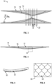
- FIG. 1 is a cross-sectional side view of an example nozzle assembly 10, according to certain embodiments of the present disclosure.
- example nozzle assembly 10 is a variable geometry nozzle assembly that utilizes magnetic fluid 12 for high efficiency expansion and/or mass flow control in fluidic systems, as discussed further below.
- nozzle assembly 10 includes an outer wall 14 (e.g., cylindrical outer wall 14), and an inner wall 16. It is noted that example inner wall 16 can be fabricated from elastic material or the like, and inner wall 16 can have variable thickness along the length of the inner wall 16.
- outer wall 14 and the inner wall 16 define an enclosed cavity 18 between the outer wall 14 and the inner wall 16.
- Example outer wall 14 includes at least one portal 20 for input and/or output of magnetic fluid 12 to or from the cavity 18.
- the magnetic fluid 12 is a ferromagnetic fluid (FF) or magnetorheological fluid (MR fluid) 12.
- ferromagnetic and magnetorheological fluids 12 are colloidal liquids made of micro and/or nanoscale ferromagnetic or ferrimagnetic particles 13 suspended in a carrier fluid 11. Magnetorheological fluids typically have larger particles 13 than ferromagnetic fluids. It is noted that magnetic fluid 12 can also be a non-Newtonian magnetic fluid 12 or a general viscous magnetic fluid 12.
- the magnetic fluid 12 When subjected to a magnetic field, the magnetic fluid 12 greatly increases its apparent viscosity, to the point of becoming a viscoelastic solid. Importantly, the yield stress of the fluid 12 when in its active or on state (e.g., when subjected to a magnetic field) can be controlled very accurately by varying the magnetic field intensity.
- the magnetic field of magnet members 24A, 24B positioned proximal to the passageway 22 of the nozzle assembly 10 can be turned off or reduced.
- the magnetic fluid 12 can be provided (e.g., pumped) into the cavity 18 (e.g., via portal 20).
- deformation of the inner wall 16 creates a variable geometry of passageway 22 of the nozzle assembly 10 (e.g., via flow of input fluid 26 to passageway 22). It is noted that a throat area 28 of passageway 22 of the nozzle assembly 10 may close or open smoothly, via deformation of the inner wall 16.
- the magnetic field of magnet members 24A, 24B positioned proximal to the nozzle assembly 10 can be turned on or increased to cause the magnetic fluid 12 in cavity 18 to become a viscoelastic solid.
- the yield stress of the fluid 12 when in its active or on state e.g., when subjected to a magnetic field
- the magnetic field of magnet members 24A, 24B can be turned on or increased to cause the magnetic fluid 12 in cavity 18 to become a viscoelastic solid, thereby allowing the solidified or semi-solidified magnetic fluid 12 to remain in a desired or achieved geometry without surface oscillations of assembly 10.
- the produced geometry of inner wall 16 can remain smooth, thereby ensuring minimum or decreased flow losses of nozzle assembly 10 (e.g., minimum or decreased flow losses of input fluid 26).
- the magnetic field of magnet members 24A, 24B can be turned on or increased to cause the magnetic fluid 12 in cavity 18 to become a viscoelastic solid, thereby allowing the solidified or semi-solidified magnetic fluid 12 to remain in the desired or achieved geometry/shape ( FIG. 3 ).
- nozzle assembly 10 when nozzle assembly 10 is utilized for certain clean gas injectors (e.g., satellite propulsors using xenon or the like; O 2 injectors; O 2 -methane burners used in metallurgy/metal cutting), no additional surface protection of inner wall 16 may be required, as the gases in such cases are high purity.
- certain clean gas injectors e.g., satellite propulsors using xenon or the like; O 2 injectors; O 2 -methane burners used in metallurgy/metal cutting
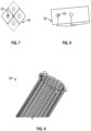
- the outer surface 30 of inner wall 16 can be a flexible surface layer 30 having a plurality of scales or plates 32 (e.g., fishlike scales 32), to increase the wear resistance of inner wall 16.
- the outer flexible surface 30 of inner wall 16 includes a plurality of abrasion resistant scales or plates 32 embedded into the elastic material of inner wall 16.
- Such design of scales/plates 32 embedded into the elastic material of inner wall 16 can allow for a combination of a smooth variable surface 30 with high or increased abrasion resistance.
- the inner wall 16 can include a flexible cover sleeve 34 fabricated from abrasion-resistant material, with the flexible cover sleeve 34 positioned around or on the inner wall 16, to increase wear resistance of inner wall 16.
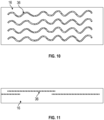
- the inner wall 16 can be fabricated from a wear resistant flexible material (e.g., rubber; polymeric material; thermoplastic elastomers such as thermoplastic polyurethane; etc.) having embedded or molded-in reinforcing fibers 36 (e.g., synthetic fibers; fiberglass fibers; carbon fibers; abrasive-resistant fibers; etc.).
- a wear resistant flexible material e.g., rubber; polymeric material; thermoplastic elastomers such as thermoplastic polyurethane; etc.
- embedded or molded-in reinforcing fibers 36 e.g., synthetic fibers; fiberglass fibers; carbon fibers; abrasive-resistant fibers; etc.
- Such wear resistant flexible material is elastic in nature, allowing the plastic to be stretched and flexed easily, while also reinforced with embedded reinforcing fibers 36.
- nozzle assembly 10 when nozzle assembly 10 is utilized as a fluidic jet (e.g., for burners or the like), the inner wall 16 can deform non-symmetrically around the passageway 22 of the nozzle assembly 10, thereby allowing a user to steer the jet in different directions.
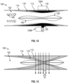
- FIGS. 12-13 are cross-sectional side views of an example valve assembly 100, according to some embodiments of the present disclosure. Similar to nozzle assembly 10 described above, example valve assembly 100 is a variable geometry valve assembly 100 that utilizes magnetic fluid 112 for mass flow control in fluidic systems.
- valve assembly 100 includes an outer wall 114 (e.g., cylindrical outer wall 114), and an inner wall 116 (e.g., fabricated from elastic material, and can have variable thickness), with enclosed cavity 118 between the outer wall 114 and the inner wall 116.
- outer wall 114 e.g., cylindrical outer wall 114
- inner wall 116 e.g., fabricated from elastic material, and can have variable thickness
- the magnetic field of magnet members 124A, 124B positioned proximal to the valve assembly 100 can be turned off or reduced.
- the magnetic fluid 112 can be provided (e.g., pumped) into the cavity 118 (e.g., via portal 120).
- deformation of the inner wall 116 creates a variable geometry of passageway 122 of the valve assembly 100 (e.g., via flow of input fluid 126 to passageway 122). It is noted that a throat area 128 of passageway 122 of the valve assembly 100 may close or open smoothly, via deformation of the inner wall 116.
- the magnetic field of magnet members 124A, 124B can be turned on or increased to cause the magnetic fluid 112 in cavity 118 to become a viscoelastic solid.
- the magnetic field of magnet members 124A, 124B can be turned on or increased to cause the magnetic fluid 112 in cavity 118 to become a viscoelastic solid, thereby allowing the solidified or semi-solidified magnetic fluid 112 to remain in a desired or achieved geometry relative to passageway 122 or relative to a valve 140 positioned in the inner passageway 122.
- example valve assembly 100 allows for an efficient and/or improved flow control rate of fluid 126 through passageway 122 of assembly 100, with minimum or decreased losses.
- the magnetic field of magnet members 124A, 124B can be turned on or increased to cause the magnetic fluid 112 in cavity 118 to become a viscoelastic solid, thereby allowing the solidified or semi-solidified magnetic fluid 112 to remain in the desired or achieved geometry/shape.
- the assemblies, systems and methods of the present disclosure including, without limitation: flexible nozzle geometry; the outer and inner walls 14, 16 ensure a smooth variation of the nozzle area and non-oscillatory fixed geometry (e.g., via the ferromagnetic fluid 12 under the magnetic field); the variable nozzle geometry allows mass flow control (e.g., choked operation) and highefficiency shockless expansion; the fish-scale 32 surface construction expands possible application to non-clean gas environments; and/or the proposed designs may be employed in gas burners, gas injectors, fluids injectors, micro-satellite propulsion; fuel injectors; etc.
- ranges disclosed herein are inclusive of the endpoints, and the endpoints are independently combinable with each other (e.g., ranges of "up to 25 wt.%, or, more specifically, 5 wt.% to 20 wt.%", is inclusive of the endpoints and all intermediate values of the ranges of "5 wt.% to 25 wt.%,” etc.).
- “Combinations” is inclusive of blends, mixtures, alloys, reaction products, and the like.
- the terms “first,” “second,” and the like, do not denote any order, quantity, or importance, but rather are used to distinguish one element from another.
Landscapes
- Engineering & Computer Science (AREA)
- General Engineering & Computer Science (AREA)
- Mechanical Engineering (AREA)
- Chemical & Material Sciences (AREA)
- Combustion & Propulsion (AREA)
- Physics & Mathematics (AREA)
- Fluid Mechanics (AREA)
- Feeding And Controlling Fuel (AREA)
Applications Claiming Priority (1)
| Application Number | Priority Date | Filing Date | Title |
|---|---|---|---|
| US17/851,581 US12569863B2 (en) | 2022-06-28 | 2022-06-28 | Variable geometry nozzle utilizing magnetic fluid |
Publications (1)
| Publication Number | Publication Date |
|---|---|
| EP4299890A1 true EP4299890A1 (de) | 2024-01-03 |
Family
ID=87003336
Family Applications (1)
| Application Number | Title | Priority Date | Filing Date |
|---|---|---|---|
| EP23181852.7A Pending EP4299890A1 (de) | 2022-06-28 | 2023-06-27 | Düse mit variabler geometrie unter verwendung von magnetflüssigkeit |
Country Status (2)
| Country | Link |
|---|---|
| US (1) | US12569863B2 (de) |
| EP (1) | EP4299890A1 (de) |
Families Citing this family (1)
| Publication number | Priority date | Publication date | Assignee | Title |
|---|---|---|---|---|
| CN120404040A (zh) * | 2025-04-25 | 2025-08-01 | 哈尔滨工业大学 | 一种用于风洞整流的微纳磁控喷嘴模块及其制备方法 |
Citations (5)
| Publication number | Priority date | Publication date | Assignee | Title |
|---|---|---|---|---|
| US3279192A (en) * | 1963-12-30 | 1966-10-18 | Gen Electric | Variable area exhaust nozzle |
| US3982722A (en) * | 1975-11-21 | 1976-09-28 | General Motors Corporation | Magnetic control valve |
| DE102008057575A1 (de) * | 2008-11-15 | 2010-05-20 | Bayerische Motoren Werke Aktiengesellschaft | Aktor mit einem magnetorheologischen Elastomer-Element |
| EP2074307B1 (de) * | 2006-10-12 | 2011-01-26 | United Technologies Corporation | Translatorisch bewegbare innenhaube mit aerodynamischen klappenabschnitten |
| US11022230B2 (en) * | 2016-03-01 | 2021-06-01 | Khs Gmbh | Actuator for controlling the fluid paths of a filling unit for a beverage filling system, filling unit, and beverage filling system |
Family Cites Families (7)
| Publication number | Priority date | Publication date | Assignee | Title |
|---|---|---|---|---|
| US2743898A (en) * | 1953-10-30 | 1956-05-01 | Exxon Research Engineering Co | Magnetic valve for control of fluid or fluidized solids flow |
| US5111992A (en) | 1991-04-19 | 1992-05-12 | United Technologies Corporation | Variable throat convergent/divergent nozzle |
| CA2481047C (en) * | 2003-09-11 | 2010-08-17 | Ga-Rew Corporation | Fluid spraying device and fluid spraying nozzle |
| US7681863B1 (en) * | 2005-09-22 | 2010-03-23 | Dana Soderlind | Electromagnetic flow-through valve |
| US10119412B2 (en) | 2013-03-13 | 2018-11-06 | United Technologies Corporation | Turbine engine adaptive low leakage air seal |
| FR3023326B1 (fr) * | 2014-07-07 | 2016-07-01 | Delphi Int Operations Luxembourg Sarl | Injecteur de carburant |
| CN112654824B (zh) | 2018-07-11 | 2023-03-14 | 保罗·奈泽 | 制冷装置及方法 |
-
2022
- 2022-06-28 US US17/851,581 patent/US12569863B2/en active Active
-
2023
- 2023-06-27 EP EP23181852.7A patent/EP4299890A1/de active Pending
Patent Citations (5)
| Publication number | Priority date | Publication date | Assignee | Title |
|---|---|---|---|---|
| US3279192A (en) * | 1963-12-30 | 1966-10-18 | Gen Electric | Variable area exhaust nozzle |
| US3982722A (en) * | 1975-11-21 | 1976-09-28 | General Motors Corporation | Magnetic control valve |
| EP2074307B1 (de) * | 2006-10-12 | 2011-01-26 | United Technologies Corporation | Translatorisch bewegbare innenhaube mit aerodynamischen klappenabschnitten |
| DE102008057575A1 (de) * | 2008-11-15 | 2010-05-20 | Bayerische Motoren Werke Aktiengesellschaft | Aktor mit einem magnetorheologischen Elastomer-Element |
| US11022230B2 (en) * | 2016-03-01 | 2021-06-01 | Khs Gmbh | Actuator for controlling the fluid paths of a filling unit for a beverage filling system, filling unit, and beverage filling system |
Also Published As
| Publication number | Publication date |
|---|---|
| US20230415174A1 (en) | 2023-12-28 |
| US12569863B2 (en) | 2026-03-10 |
Similar Documents
| Publication | Publication Date | Title |
|---|---|---|
| CA2889636C (en) | Valve cage having zero dead band between noise abatement and high capacity flow sections | |
| EP1553281B1 (de) | Vorrichtung zur Reduktion des Austrittslärms von Strahltriebwerken unter Benutzung von oszillierenden Strahlen | |
| EP4299890A1 (de) | Düse mit variabler geometrie unter verwendung von magnetflüssigkeit | |
| AU2019411947B8 (en) | Throat offset fluidic thurst vectoring nozzle having asymmetric backbody profile | |
| US20210003285A1 (en) | Systems, Apparatuses And Methods For Improved Rotation Detonation Engines | |
| EP2310731B1 (de) | Drosselventil mit strömungshemmenden aussparungen | |
| US7159383B2 (en) | Apparatus, method and system for gas turbine engine noise reduction | |
| EP2137395B1 (de) | Lavaldüse eines raketenantriebs | |
| EP2616721B1 (de) | Hülsendichtung für schieber | |
| WO2008021618A2 (en) | Multiple vane variable geometry nozzle | |
| WO2018226451A1 (en) | Fixed cone sleeve valve with finger extensions on sleeve gate for cavitation suppression and multi-jet discharge member | |
| EP1998035B1 (de) | Fluidvektorsteuerung für eine Abgasdüse | |
| JP2020148197A (ja) | 噴流噴射ノズルおよび、推力のベクトル制御方法。 | |
| US10337648B2 (en) | Fixed cone sleeve valve with finger extensions on sleeve gate for cavitation suppression | |
| US20250043870A1 (en) | Fluid flow control devices and related systems and methods | |
| US20070029408A1 (en) | Throttleable swirling injector for combustion chambers | |
| US3529619A (en) | Valve device | |
| KR101162886B1 (ko) | 유량제어밸브 | |
| EP2655894B1 (de) | Zyklonaufzug und verwendungsverfahren dafür | |
| US8985965B2 (en) | Cyclonic elevator and method for using same | |
| UA65541C2 (en) | Method and device for formation of hydrodynamic lift or propulsive force | |
| NZ701725B2 (en) | High-speed check valve suitable for cryogens and high reverse pressure |
Legal Events
| Date | Code | Title | Description |
|---|---|---|---|
| PUAI | Public reference made under article 153(3) epc to a published international application that has entered the european phase |
Free format text: ORIGINAL CODE: 0009012 |
|
| STAA | Information on the status of an ep patent application or granted ep patent |
Free format text: STATUS: THE APPLICATION HAS BEEN PUBLISHED |
|
| AK | Designated contracting states |
Kind code of ref document: A1 Designated state(s): AL AT BE BG CH CY CZ DE DK EE ES FI FR GB GR HR HU IE IS IT LI LT LU LV MC ME MK MT NL NO PL PT RO RS SE SI SK SM TR |
|
| STAA | Information on the status of an ep patent application or granted ep patent |
Free format text: STATUS: REQUEST FOR EXAMINATION WAS MADE |
|
| 17P | Request for examination filed |
Effective date: 20240703 |
|
| RBV | Designated contracting states (corrected) |
Designated state(s): AL AT BE BG CH CY CZ DE DK EE ES FI FR GB GR HR HU IE IS IT LI LT LU LV MC ME MK MT NL NO PL PT RO RS SE SI SK SM TR |
|
| STAA | Information on the status of an ep patent application or granted ep patent |
Free format text: STATUS: EXAMINATION IS IN PROGRESS |
|
| 17Q | First examination report despatched |
Effective date: 20251106 |