EP4299882A1 - Bearing carrier support with reduced axial length - Google Patents
Bearing carrier support with reduced axial length Download PDFInfo
- Publication number
- EP4299882A1 EP4299882A1 EP23173834.5A EP23173834A EP4299882A1 EP 4299882 A1 EP4299882 A1 EP 4299882A1 EP 23173834 A EP23173834 A EP 23173834A EP 4299882 A1 EP4299882 A1 EP 4299882A1
- Authority
- EP
- European Patent Office
- Prior art keywords
- carrier support
- bearing carrier
- bearing
- struts
- support
- Prior art date
- Legal status (The legal status is an assumption and is not a legal conclusion. Google has not performed a legal analysis and makes no representation as to the accuracy of the status listed.)
- Granted
Links
- 230000004323 axial length Effects 0.000 title claims description 6
- 230000003068 static effect Effects 0.000 claims abstract description 11
- 239000002131 composite material Substances 0.000 claims description 6
- 238000004519 manufacturing process Methods 0.000 claims description 4
- 239000000654 additive Substances 0.000 claims description 3
- 230000000996 additive effect Effects 0.000 claims description 3
- OKTJSMMVPCPJKN-UHFFFAOYSA-N Carbon Chemical compound [C] OKTJSMMVPCPJKN-UHFFFAOYSA-N 0.000 claims description 2
- 229910000831 Steel Inorganic materials 0.000 claims description 2
- RTAQQCXQSZGOHL-UHFFFAOYSA-N Titanium Chemical compound [Ti] RTAQQCXQSZGOHL-UHFFFAOYSA-N 0.000 claims description 2
- 229910052799 carbon Inorganic materials 0.000 claims description 2
- 239000000835 fiber Substances 0.000 claims description 2
- 239000010959 steel Substances 0.000 claims description 2
- 239000010936 titanium Substances 0.000 claims description 2
- 229910052719 titanium Inorganic materials 0.000 claims description 2
- 239000000463 material Substances 0.000 description 12
- 238000002485 combustion reaction Methods 0.000 description 4
- 230000009467 reduction Effects 0.000 description 4
- 230000001141 propulsive effect Effects 0.000 description 3
- 238000003491 array Methods 0.000 description 2
- 238000005452 bending Methods 0.000 description 2
- 230000006835 compression Effects 0.000 description 2
- 238000007906 compression Methods 0.000 description 2
- 239000000446 fuel Substances 0.000 description 2
- 229910052751 metal Inorganic materials 0.000 description 2
- 239000002184 metal Substances 0.000 description 2
- 238000000034 method Methods 0.000 description 2
- 229920001875 Ebonite Polymers 0.000 description 1
- 239000000969 carrier Substances 0.000 description 1
- 230000007717 exclusion Effects 0.000 description 1
- 239000000203 mixture Substances 0.000 description 1
- 238000012986 modification Methods 0.000 description 1
- 230000004048 modification Effects 0.000 description 1
- 238000004806 packaging method and process Methods 0.000 description 1
- 230000004044 response Effects 0.000 description 1
- 238000004088 simulation Methods 0.000 description 1
- 238000011144 upstream manufacturing Methods 0.000 description 1
Images


Classifications
-
- F—MECHANICAL ENGINEERING; LIGHTING; HEATING; WEAPONS; BLASTING
- F16—ENGINEERING ELEMENTS AND UNITS; GENERAL MEASURES FOR PRODUCING AND MAINTAINING EFFECTIVE FUNCTIONING OF MACHINES OR INSTALLATIONS; THERMAL INSULATION IN GENERAL
- F16C—SHAFTS; FLEXIBLE SHAFTS; ELEMENTS OR CRANKSHAFT MECHANISMS; ROTARY BODIES OTHER THAN GEARING ELEMENTS; BEARINGS
- F16C35/00—Rigid support of bearing units; Housings, e.g. caps, covers
- F16C35/02—Rigid support of bearing units; Housings, e.g. caps, covers in the case of sliding-contact bearings
-
- F—MECHANICAL ENGINEERING; LIGHTING; HEATING; WEAPONS; BLASTING
- F01—MACHINES OR ENGINES IN GENERAL; ENGINE PLANTS IN GENERAL; STEAM ENGINES
- F01D—NON-POSITIVE DISPLACEMENT MACHINES OR ENGINES, e.g. STEAM TURBINES
- F01D25/00—Component parts, details, or accessories, not provided for in, or of interest apart from, other groups
- F01D25/16—Arrangement of bearings; Supporting or mounting bearings in casings
- F01D25/162—Bearing supports
- F01D25/164—Flexible supports; Vibration damping means associated with the bearing
-
- F—MECHANICAL ENGINEERING; LIGHTING; HEATING; WEAPONS; BLASTING
- F01—MACHINES OR ENGINES IN GENERAL; ENGINE PLANTS IN GENERAL; STEAM ENGINES
- F01D—NON-POSITIVE DISPLACEMENT MACHINES OR ENGINES, e.g. STEAM TURBINES
- F01D25/00—Component parts, details, or accessories, not provided for in, or of interest apart from, other groups
- F01D25/16—Arrangement of bearings; Supporting or mounting bearings in casings
- F01D25/162—Bearing supports
-
- F—MECHANICAL ENGINEERING; LIGHTING; HEATING; WEAPONS; BLASTING
- F02—COMBUSTION ENGINES; HOT-GAS OR COMBUSTION-PRODUCT ENGINE PLANTS
- F02C—GAS-TURBINE PLANTS; AIR INTAKES FOR JET-PROPULSION PLANTS; CONTROLLING FUEL SUPPLY IN AIR-BREATHING JET-PROPULSION PLANTS
- F02C7/00—Features, components parts, details or accessories, not provided for in, or of interest apart form groups F02C1/00 - F02C6/00; Air intakes for jet-propulsion plants
- F02C7/06—Arrangements of bearings; Lubricating
-
- F—MECHANICAL ENGINEERING; LIGHTING; HEATING; WEAPONS; BLASTING
- F05—INDEXING SCHEMES RELATING TO ENGINES OR PUMPS IN VARIOUS SUBCLASSES OF CLASSES F01-F04
- F05D—INDEXING SCHEME FOR ASPECTS RELATING TO NON-POSITIVE-DISPLACEMENT MACHINES OR ENGINES, GAS-TURBINES OR JET-PROPULSION PLANTS
- F05D2220/00—Application
- F05D2220/30—Application in turbines
- F05D2220/32—Application in turbines in gas turbines
-
- F—MECHANICAL ENGINEERING; LIGHTING; HEATING; WEAPONS; BLASTING
- F05—INDEXING SCHEMES RELATING TO ENGINES OR PUMPS IN VARIOUS SUBCLASSES OF CLASSES F01-F04
- F05D—INDEXING SCHEME FOR ASPECTS RELATING TO NON-POSITIVE-DISPLACEMENT MACHINES OR ENGINES, GAS-TURBINES OR JET-PROPULSION PLANTS
- F05D2230/00—Manufacture
- F05D2230/60—Assembly methods
- F05D2230/64—Assembly methods using positioning or alignment devices for aligning or centring, e.g. pins
-
- F—MECHANICAL ENGINEERING; LIGHTING; HEATING; WEAPONS; BLASTING
- F05—INDEXING SCHEMES RELATING TO ENGINES OR PUMPS IN VARIOUS SUBCLASSES OF CLASSES F01-F04
- F05D—INDEXING SCHEME FOR ASPECTS RELATING TO NON-POSITIVE-DISPLACEMENT MACHINES OR ENGINES, GAS-TURBINES OR JET-PROPULSION PLANTS
- F05D2240/00—Components
- F05D2240/50—Bearings
- F05D2240/54—Radial bearings
-
- F—MECHANICAL ENGINEERING; LIGHTING; HEATING; WEAPONS; BLASTING
- F05—INDEXING SCHEMES RELATING TO ENGINES OR PUMPS IN VARIOUS SUBCLASSES OF CLASSES F01-F04
- F05D—INDEXING SCHEME FOR ASPECTS RELATING TO NON-POSITIVE-DISPLACEMENT MACHINES OR ENGINES, GAS-TURBINES OR JET-PROPULSION PLANTS
- F05D2260/00—Function
- F05D2260/30—Retaining components in desired mutual position
-
- F—MECHANICAL ENGINEERING; LIGHTING; HEATING; WEAPONS; BLASTING
- F16—ENGINEERING ELEMENTS AND UNITS; GENERAL MEASURES FOR PRODUCING AND MAINTAINING EFFECTIVE FUNCTIONING OF MACHINES OR INSTALLATIONS; THERMAL INSULATION IN GENERAL
- F16C—SHAFTS; FLEXIBLE SHAFTS; ELEMENTS OR CRANKSHAFT MECHANISMS; ROTARY BODIES OTHER THAN GEARING ELEMENTS; BEARINGS
- F16C2220/00—Shaping
- F16C2220/20—Shaping by sintering pulverised material, e.g. powder metallurgy
-
- F—MECHANICAL ENGINEERING; LIGHTING; HEATING; WEAPONS; BLASTING
- F16—ENGINEERING ELEMENTS AND UNITS; GENERAL MEASURES FOR PRODUCING AND MAINTAINING EFFECTIVE FUNCTIONING OF MACHINES OR INSTALLATIONS; THERMAL INSULATION IN GENERAL
- F16C—SHAFTS; FLEXIBLE SHAFTS; ELEMENTS OR CRANKSHAFT MECHANISMS; ROTARY BODIES OTHER THAN GEARING ELEMENTS; BEARINGS
- F16C2360/00—Engines or pumps
- F16C2360/23—Gas turbine engines
Definitions
- the present invention relates to a bearing carrier support, more specifically a bearing carrier support that provide a semi-flexible support to the rotor axial location (e.g. ball) bearing, used in conjunction with a squeeze film damper, for a rotary shaft of a gas turbine engine.
- a bearing carrier support more specifically a bearing carrier support that provide a semi-flexible support to the rotor axial location (e.g. ball) bearing, used in conjunction with a squeeze film damper, for a rotary shaft of a gas turbine engine.
- a bearing carrier support is a component designed to provide a semi-flexible support to the rotor axial location bearing, typically a ball bearing and used in conjunction with a squeeze film dampener, for a rotating shaft, e.g. of a gas turbine engine.
- a bearing carrier support typically has a series of spring bars arrayed circumferentially in between a pair of flanges. The flanges locate the bearing in the housing/structure.
- the radial stiffness of the bearing carrier support is generally such that it will support the rotor under normal operating conditions, but when the rotor exhibits vibration, due to out of balance or crossing a mode in the running range, the squeeze film dampener is activated and the energy is transferred in the squeeze film.
- the axial stiffness needs to be very high to react the thrust loads.
- the bearing carrier support is typically arranged so that the axial loads are taken along the bars in tension and the radial loads taken perpendicular to the bars resulting in bending.
- the length and cross section of spring bars is driven by separate axial and radial stiffness requirements, which lend them to be long slender spring bars.
- the minimum achievable length is constrained by the need to achieve the desired radial stiffness whilst limiting bar bending stresses due to squeeze film dampener orbit.
- patent US 7857519 B2 discloses a compact squirrel-cage bearing support that has a plurality of beams interconnecting a first end portion to a second end portion. The length of the beams is greater than the axial spacing between the first end portion and the second end portion.
- German patent application DE 202010206588 A1 discloses a bearing carrier for support of a rotary bearing of a rotating shaft of a gas turbine, e.g. flight gas turbine, having a flange portion with a supporting structure of the gas turbine, a bearing section, in which at least one rotary bearing is receivable, and with a cage portion in the axial direction of the bearing carrier between the flange portion and the bearing portion is arranged, and a plurality of circumferentially distributed strut.
- the flange portion and the bearing section are connected to one another.
- a bearing carrier support for connecting a rotary shaft of a gas turbine engine to a static portion of the gas turbine engine
- the bearing carrier support comprising: a bearing portion for supporting the rotary shaft; a flange portion for attaching the bearing carrier support to the static portion of the gas turbine engine; and a support portion that connects the flange portion and the bearing portion, the support portion comprising a plurality of circumferentially distributed struts that are axially aligned with respect to the rotary shaft; wherein the number of struts is at least 500 and the diameter of each strut is no more than 3 mm.
- each strut is no more than 1.5 mm.
- the diameter of each struct is no more than 0.5 mm.
- each strut is equal.
- the number of struts is at least 1000.
- the number of struts is at least 5000.
- the struts have a constant diameter along their axial length.
- the struts are non-continuously distributed such that there are gaps within the circumferential distribution.
- the struts comprise steel, titanium, carbon fibre, or composite reinforced rods.
- the struts are welded, bonded or trapped between the flange portion and the bearing portion.
- At least one snubber extends from the bearing portion to provide a hard stop against the flange portion.
- At least one anti-rotational stop extends from the flange portion to provide a hard stop against a side face of the snubber.
- the bearing carrier support is manufactured using Additive Layer Manufacturing.
- a gas turbine engine that includes a bearing carrier support of the first aspect.
- the present invention provides a bearing carrier support, for example, to provide a semi-flexible support to the rotor axial location (e.g. ball) bearing, used in conjunction with a squeeze film dampener, for a rotating shaft of a gas turbine engine.
- Figures 1, 2 and 3 describe a gas turbine engine for which the bearing carrier of the present invention is suitable for use, although the person skilled in the art would appreciate the bearing carrier support could be used to support the rotor axial location of a shaft of any gas turbine engine or indeed a shaft of any machine or apparatus.
- the geometry of the gas turbine engine 10, and components thereof, is defined by a conventional axis system, comprising an axial direction (which is aligned with the rotational axis 9), a radial direction (in the bottom-to-top direction in Figure 1 ), and a circumferential direction (perpendicular to the page in the Figure 1 view).
- the axial, radial and circumferential directions are mutually perpendicular.
- FIG. 1 illustrates a gas turbine engine 10 having a principal rotational axis 9.
- the engine 10 comprises an air intake 12 and a propulsive fan 23 that generates two airflows: a core airflow A and a bypass airflow B.
- the gas turbine engine 10 comprises a core 11 that receives the core airflow A.
- the engine core 11 comprises, in axial flow series, a low pressure compressor 14, a high-pressure compressor 15, combustion equipment 16, a high-pressure turbine 17, a low pressure turbine 19 and a core exhaust nozzle 20.
- a nacelle 21 surrounds the gas turbine engine 10 and defines a bypass duct 22 and a bypass exhaust nozzle 18.
- the bypass airflow B flows through the bypass duct 22.
- the fan 23 is attached to and driven by the low pressure turbine 19 via a shaft 26 and an epicyclic gearbox 30.
- the core airflow A is accelerated and compressed by the low pressure compressor 14 and directed into the high pressure compressor 15 where further compression takes place.
- the compressed air exhausted from the high pressure compressor 15 is directed into the combustion equipment 16 where it is mixed with fuel and the mixture is combusted.
- the resultant hot combustion products then expand through, and thereby drive, the high pressure and low pressure turbines 17, 19 before being exhausted through the core exhaust nozzle 20 to provide some propulsive thrust.
- the high pressure turbine 17 drives the high pressure compressor 15 by a suitable interconnecting shaft 27.
- the fan 23 generally provides the majority of the propulsive thrust.
- the epicyclic gearbox 30 is a reduction gearbox.
- FIG. 2 An exemplary arrangement for a geared fan gas turbine engine 10 is shown in Figure 2 .
- the low pressure turbine 19 (see Figure 1 ) drives the shaft 26, which is coupled to a sun wheel, or sun gear, 28 of the epicyclic gear arrangement 30.
- a sun wheel, or sun gear, 28 of the epicyclic gear arrangement 30 Radially outwardly of the sun gear 28 and intermeshing therewith is a plurality of planet gears 32 that are coupled together by a planet carrier 34.
- the planet carrier 34 constrains the planet gears 32 to precess around the sun gear 28 in synchronicity whilst enabling each planet gear 32 to rotate about its own axis.
- the planet carrier 34 is coupled via linkages 36 to the fan 23 in order to drive its rotation about the engine axis 9.
- an annulus or ring gear 38 Radially outwardly of the planet gears 32 and intermeshing therewith is an annulus or ring gear 38 that is coupled, via linkages 40, to a stationary supporting structure 24.
- low pressure turbine and “low pressure compressor” as used herein may be taken to mean the lowest pressure turbine stages and lowest pressure compressor stages (i.e. not including the fan 23) respectively and/or the turbine and compressor stages that are connected together by the interconnecting shaft 26 with the lowest rotational speed in the engine (i.e. not including the gearbox output shaft that drives the fan 23).
- the "low pressure turbine” and “low pressure compressor” referred to herein may alternatively be known as the "intermediate pressure turbine” and “intermediate pressure compressor”. Where such alternative nomenclature is used, the fan 23 may be referred to as a first, or lowest pressure, compression stage.
- the epicyclic gearbox 30 is shown by way of example in greater detail in Figure 3 .
- Each of the sun gear 28, planet gears 32 and ring gear 38 comprise teeth about their periphery to intermesh with the other gears. However, for clarity only exemplary portions of the teeth are illustrated in Figure 3 .
- Practical applications of a planetary epicyclic gearbox 30 generally comprise at least three planet gears 32.
- the epicyclic gearbox 30 illustrated by way of example in Figures 2 and 3 is of the planetary type, in that the planet carrier 34 is coupled to an output shaft via linkages 36, with the ring gear 38 fixed.
- the epicyclic gearbox 30 may be a star arrangement, in which the planet carrier 34 is held fixed, with the ring (or annulus) gear 38 allowed to rotate. In such an arrangement the fan 23 is driven by the ring gear 38.
- the gearbox 30 may be a differential gearbox in which the ring gear 38 and the planet carrier 34 are both allowed to rotate.
- the present invention concerns a bearing carrier support that is, for example, to provide a semi-flexible support to the rotor axial location (e.g. ball) bearing, used in conjunction with or without a squeeze film dampener, for a rotating shaft of a gas turbine engine.
- a semi-flexible support to the rotor axial location (e.g. ball) bearing, used in conjunction with or without a squeeze film dampener, for a rotating shaft of a gas turbine engine.
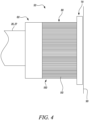
- the bearing carrier support 50 of the present invention comprises a bearing portion 60, a flange portion 70 and a support portion 80.
- FIG. 4 A first embodiment of such a bearing carrier support is shown in Figure 4 .
- the bearing carrier support 50 interconnects the rotating shafts 26, 27 of a gas turbine engine with the static portion 90 of the gas turbine engine. Under normal engine operating conditions, the bearing carrier support 50 supports the shafts 26,27 in their axial position.
- the bearing portion 60 is configured to receive a bearing (not shown) and the bearing locates the rotary shafts 26, 27.
- the bearing portion can be any suitable form for that purpose, for example, an annular section.
- the bearing portion 60 can be formed out of any suitable material for its purpose, for example metallic or composite.
- the bearing portion 60 is designed to house a bearing allowing the shaft 26,27 of the turbine engine to rotate.
- the flange portion 70 attaches the bearing carrier support 50 to a static portion 90 of a gas turbine engine 10.
- the flange portion 70 can be any suitable form for that purpose, for example can be annular.
- the flange portion 70 can be formed from any suitable material for its purpose, for example metal or composite.
- the flange portion 70 may have a plurality of holes that correspond to holes within the gas turbine structure 90.
- the flange portion 70 can be removable fixed to the gas turbine structure with fixings, e.g. bolts.
- the flange portion 70 may be permanently fixed to the gas turbine structure, e.g. welded.
- the flange portion 70 is connected to the static portion 90 of the gas turbine engine 10 so that the shaft 26,27 is axially position.
- the bearing (including the carrier support element) is typically located within a bearing housing which is located within or integral to a bearing support structure, or static structure. This transfers the bearing loads out to the casings and then airframe, via the engine mounts.
- the support portion 80 connects the flange portion 70 and the bearing portion 60.
- the support portion 80 comprises a plurality of circumferentially distributed struts 100, shown in Figure 5 , that are axially aligned with respect to the rotary shaft 26,27.
- the struts 100 extend axially between the bearing portion 60 and the flange portion 70 and attach at their distal ends. Loads are typically absorbed through the squeeze film dampener and then absorbed.
- the number of struts 100 is at least 500, for example from 500 to 1000 or from 500 and 5000.
- the struts 100 may be formed from any suitable material, for example metallic or composite.
- the struts 100 may not be the same material, for example an individual struts 110 in an array of struts 100 may be different materials.
- the diameter of the individual strut 110 may be no more than 3 mm, for example from 1.5 mm to 3.0 mm or from 0.5 mm to 3.0 mm.
- the diameter of the individual strut 110 may or may not vary along its length.
- the individual strut 110 in an array of struts 100 may have the same or different diameters. In the example shown at Figure 4 and 5 the individual struts 110 have a constant diameter and are all equal.
- the array of struts 100 may be distributed uniformly or non-uniformly.
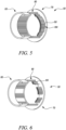
- the array of struts 100 is positioned in separate bundles, as shown in Figure 6 .
- the bundles may consist of the same or different numbers of individual struts 110.
- the bundles may be distributed uniformly of non-uniformly.
- the individual struts 110 have different diameters.
- the variation in strut diameters is shown more clearly in Figure 8 , which is a close-up view of the elliptical area shown in Figure 7 .
- the individual struts 110 while varying in diameter, are all circular in diameter.
- the individual struts 110 may have a cross section that is not circular, for example they may be square, oval or elliptical in cross-section.
- the individual struts 110 may be specifically designed to react the vibration modes of the rotating shaft 26,27.
- the individual struts 110 may be specifically designed to be stiffer in one direction over the other direction.
- the individual struts 110 may be specifically designed to reduce the overall size and improve the packaging within the design space.
- Figure 9 shows a fourth embodiment of the bearing carrier support 50 of the present invention.
- This embodiment resembles the first embodiment except it has a snubber 120.
- the snubber 120 limits the deformation of the individual struts 110 by providing a hard stop between the bearing portion 60 and the flange portion 70 if an overload is encountered that may cause buckling of the individual struts 110, allowing the overload to bypass the array of struts 100.
- the snubber 120 may extend from the flange portion 70 to form an abutment face that is engageable with the bearing portion 60.
- the distance between the abutment face of the snubber 120 and the corresponding bearing portion 60 or flange portion 70 may be less than 1 mm.
- the snubber 120 is radially external to the array of struts 100.
- the snubber 120 may be radially internal to the array of struts 100.
- the snubber 120 may be interspersed within the array of struts 110.
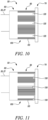
- Figure 10 shows a fifth embodiment of the bearing carrier support 50 of the present invention.
- a plurality of snubbers 120 extend from the bearing portion 60 to form an abutment face that is engageable with the flange portion 70.
- the plurality of snubbers 120 may extend from the flange portion 70 to form an abutment face that is engageable with the bearing portion 60.
- the plurality of snubbers 120 is integral with the bearing portion 60 and is therefore formed of the same material.
- the plurality of snubbers 120 is not integral with the bearing portion 60 and so the plurality of 120 snubbers and the bearing portion 60 can be formed of different material, for example, the plurality of snubbers 120 may be formed of a hard rubber and the bearing portion 60 may be formed of a metal.
- the plurality of snubbers 120 may be positioned intermittently around the circumference of the flanges. The intermittent plurality of snubbers 120 may be equally spaced.
- FIG 11 shows a sixth embodiment of the bearing carrier support 50 of the present invention.
- anti-rotational stops 130 extend from the flange portion 70 to form an abutment face that is engageable with the side face of the snubbers 120.
- the anti-rotational stops 130 prevent a circumferential twisting of the array of struts 100 by providing a hard stop between the snubber 120 of the bearing portion 60 and the anti-rotational stop 130 of the flange portion 70 if an overload is encountered that may cause buckling of the array of struts 100, allowing the overload to bypass the array of struts 110.
- the anti-rotational stop 130 may extend from the bearing portion 60 to form an abutment face that is engageable with side face of the snubbers 120 that extend from the flange portion 70.
- the distance between the abutment face of the anti-rotational stop 130 and the side face of the corresponding snubber 120 may be less than 1 mm.
- Bearing carrier supports 50 of the present invention may be fabricated using a conventional manufacturing process, an additive layer manufacturing (ALM) technique or a combination of these.
- the bearing carrier support 50 may be manufactured from any suitable material or combination of materials selected based on the specific application.
- the bearing portion 60, the flange portion 70 and the support portion 80 may be the same material of different material.
- the individual struts 110 may be bonded, welded, co-cured (if composite) or trapped.
- the bearing carrier support 50 allows for the resilient radial movement of the bearing (not shown) in response to the radial forces that are induced by the vibrations of the rotating shaft 26,27.
- the bearing carrier support 50 also provide a self-centring support for the shaft 26,27.
- the bearing carrier support 50 provides a support with high axial stiffness but low radial and torsional stiffnesses.
- the bearing carrier support 50 may comprise a combination of different arrays of struts 100.
- the size, number and spacing of the individual struts 110 may be selected on factors such as material properties, operating conditions and dynamic properties required for the bearing carrier support 50. Conventional numerical simulation and modelling techniques commonly used in the art may be used to determine a suitable design configuration of the bearing carrier support 50.
- This provides a bearing carrier support 50 with a reduced weight and axial length when compared to existing designs.
- the aspect ratio and arrangement of the array of struts 100 makes them radially compliant, thus stresses can be kept low for a given orbit size and individual strut 110 length. Adequate radial and axial stiffness is achieved by increasing the total individual strut 110 count. This results in reduced component size (particularly axial length) and weight, whilst maintaining the current ability to achieve different axial and radial stiffness targets.
- the reduction in size allows the bearing carrier support 50 to be integrated into the bearing with an overall reduction in required axial length.
Landscapes
- Engineering & Computer Science (AREA)
- General Engineering & Computer Science (AREA)
- Mechanical Engineering (AREA)
- Support Of The Bearing (AREA)
Abstract
Description
- The present invention relates to a bearing carrier support, more specifically a bearing carrier support that provide a semi-flexible support to the rotor axial location (e.g. ball) bearing, used in conjunction with a squeeze film damper, for a rotary shaft of a gas turbine engine.
- A bearing carrier support is a component designed to provide a semi-flexible support to the rotor axial location bearing, typically a ball bearing and used in conjunction with a squeeze film dampener, for a rotating shaft, e.g. of a gas turbine engine.
- A bearing carrier support typically has a series of spring bars arrayed circumferentially in between a pair of flanges. The flanges locate the bearing in the housing/structure.
- The radial stiffness of the bearing carrier support is generally such that it will support the rotor under normal operating conditions, but when the rotor exhibits vibration, due to out of balance or crossing a mode in the running range, the squeeze film dampener is activated and the energy is transferred in the squeeze film. The axial stiffness needs to be very high to react the thrust loads.
- The bearing carrier support is typically arranged so that the axial loads are taken along the bars in tension and the radial loads taken perpendicular to the bars resulting in bending. The length and cross section of spring bars is driven by separate axial and radial stiffness requirements, which lend them to be long slender spring bars. The minimum achievable length is constrained by the need to achieve the desired radial stiffness whilst limiting bar bending stresses due to squeeze film dampener orbit.
- These requirements result in relatively long bearing carriers, which increases engine centreline length. That is a significant driver of engine weight, which is undesirable in aerospace applications as weight increases specific fuel consumption (SPC). The components also tend to be expensive as they need to be machined into relatively long slender bars or precision assembled. This limits the opportunity for weight, cost and space envelope reduction much beyond what has already been achieved.
- United states patent
US 7857519 B2 discloses a compact squirrel-cage bearing support that has a plurality of beams interconnecting a first end portion to a second end portion. The length of the beams is greater than the axial spacing between the first end portion and the second end portion. - German patent application
DE 202010206588 A1 discloses a bearing carrier for support of a rotary bearing of a rotating shaft of a gas turbine, e.g. flight gas turbine, having a flange portion with a supporting structure of the gas turbine, a bearing section, in which at least one rotary bearing is receivable, and with a cage portion in the axial direction of the bearing carrier between the flange portion and the bearing portion is arranged, and a plurality of circumferentially distributed strut. The flange portion and the bearing section are connected to one another. - There is however a need for an improved bearing carrier support or at least a bearing carrier support that provides a useful alternative to known bearing carrier supports.
- In a first aspect there is provided a bearing carrier support for connecting a rotary shaft of a gas turbine engine to a static portion of the gas turbine engine, the bearing carrier support comprising: a bearing portion for supporting the rotary shaft; a flange portion for attaching the bearing carrier support to the static portion of the gas turbine engine; and a support portion that connects the flange portion and the bearing portion, the support portion comprising a plurality of circumferentially distributed struts that are axially aligned with respect to the rotary shaft; wherein the number of struts is at least 500 and the diameter of each strut is no more than 3 mm.
- In some embodiments the diameter of each strut is no more than 1.5 mm.
- In some embodiments the diameter of each struct is no more than 0.5 mm.
- In some embodiments the diameter of each strut is equal.
- In some embodiments the number of struts is at least 1000.
- In some embodiments the number of struts is at least 5000.
- In some embodiments the struts have a constant diameter along their axial length.
- In some embodiments the struts are non-continuously distributed such that there are gaps within the circumferential distribution.
- In some embodiments the struts comprise steel, titanium, carbon fibre, or composite reinforced rods.
- In some embodiments the struts are welded, bonded or trapped between the flange portion and the bearing portion.
- In some embodiments at least one snubber extends from the bearing portion to provide a hard stop against the flange portion.
- In some embodiments at least one anti-rotational stop extends from the flange portion to provide a hard stop against a side face of the snubber.
- In some embodiments the bearing carrier support is manufactured using Additive Layer Manufacturing.
- In a second aspect there is provided a gas turbine engine that includes a bearing carrier support of the first aspect.
- Throughout this specification and in the claims that follow, unless the context requires otherwise, the word "comprise" or variations such as "comprises" and "comprising", will be understood to imply the inclusion of a stated integer or group of integers but not the exclusion of any other stated integer or group of integers.
- The skilled person will appreciate that except where mutually exclusive, a feature or parameter described in relation to any one of the above aspects may be applied to any other aspect. Furthermore, except where mutually exclusive, any feature or parameter described herein may be applied to any aspect and/or combined with any other feature or parameter described herein.
- Embodiments will now be described by way of example only, with reference to the Figures, in which:
-
Figure 1 is a sectional side view of a gas turbine engine, more particularly a geared turbofan aircraft engine; -
Figure 2 is a close-up sectional side view of an upstream portion of the gas turbine engine shown inFigure 1 ; -
Figure 3 is a partially cut-away view of a gearbox for the gas turbine engine show inFigures 1 and 2 ; -
Figure 4 is a side view of a first embodiment of the bearing carrier support of the present invention. -
Figure 5 is a sectional perspective view of the bearing carrier support ofFigure 4 . -
Figure 6 is a sectional perspective view of a second embodiment of the bearing carrier support of the present invention where the array of struts has intermediate gaps. -
Figure 7 is a sectional perspective view of a third embodiment of the bearing carrier support of the present invention where the arrays of struts comprises struts of varying diameter. -
Figure 8 is a close-up view of the part of the bearing carrier support in the elliptical region shown inFigure 7 from which the struts of varying diameter are more clearly seen. -
Figure 9 is a side view of a fourth embodiment of the bearing carrier support of the present invention that includes a circumferential snubber. -
Figure 10 is a sectional perspective view of a fifth embodiment of the bearing carrier support of the present invention that includes a plurality of snubbers. -
Figure 11 is a side view of the sixth embodiment of the bearing carrier support of the present invention that includes anti-rotational stops. - The following table lists the reference numerals used in the drawings with the features to which they refer:
Ref no. Feature Figure A Core airflow 1 B Bypass airflow 1 9 Principal and rotational axis (of engine) 1, 2 10 Gas turbine engine 1 11 Engine core 1 12 Air intake 1 14 Low pressure compressor 1 15 High pressure compressor 1 16 Combustion equipment 1 17 High pressure turbine 1 18 Bypass exhaust nozzle 1 19 Low pressure turbine 1 20 Core exhaust nozzle 1 21 Fan nacelle 1 22 Bypass duct 1 23 Fan 1, 2 24 Stationary supporting structure 2 26 Shaft 1, 2, 4 27 Shaft 1, 4 28 Sun gear 2 30 Epicyclic gearbox 1, 2 32 Planet gear 2 34 Planet carrier 2 36 Linkage 2 38 Ring gear 2 40 Linkage 2 50 Bearing carrier support 4, 5, 6, 7, 8 60 Bearing portion 4, 5, 6, 7, 8 70 Flange portion 4, 5, 6, 7, 8 80 Support portion 4, 5, 6, 7, 8 90 Static portion 4 100 Array of struts 4, 5, 6, 7, 8 110 Individual strut 4, 5, 6, 7, 8 120 Snubber 9, 10, 11 130 Anti-rotational stop 11 - Aspects and embodiments of the present invention will now be discussed with reference to the accompanying figures. Further aspects and embodiments will be apparent to those skilled in the art.
- The present invention provides a bearing carrier support, for example, to provide a semi-flexible support to the rotor axial location (e.g. ball) bearing, used in conjunction with a squeeze film dampener, for a rotating shaft of a gas turbine engine.
Figures 1, 2 and3 describe a gas turbine engine for which the bearing carrier of the present invention is suitable for use, although the person skilled in the art would appreciate the bearing carrier support could be used to support the rotor axial location of a shaft of any gas turbine engine or indeed a shaft of any machine or apparatus. - The geometry of the
gas turbine engine 10, and components thereof, is defined by a conventional axis system, comprising an axial direction (which is aligned with the rotational axis 9), a radial direction (in the bottom-to-top direction inFigure 1 ), and a circumferential direction (perpendicular to the page in theFigure 1 view). The axial, radial and circumferential directions are mutually perpendicular. -
Figure 1 illustrates agas turbine engine 10 having a principalrotational axis 9. Theengine 10 comprises anair intake 12 and apropulsive fan 23 that generates two airflows: a core airflow A and a bypass airflow B. Thegas turbine engine 10 comprises acore 11 that receives the core airflow A. Theengine core 11 comprises, in axial flow series, alow pressure compressor 14, a high-pressure compressor 15,combustion equipment 16, a high-pressure turbine 17, alow pressure turbine 19 and acore exhaust nozzle 20. Anacelle 21 surrounds thegas turbine engine 10 and defines abypass duct 22 and abypass exhaust nozzle 18. The bypass airflow B flows through thebypass duct 22. Thefan 23 is attached to and driven by thelow pressure turbine 19 via ashaft 26 and anepicyclic gearbox 30. - In use, the core airflow A is accelerated and compressed by the
low pressure compressor 14 and directed into thehigh pressure compressor 15 where further compression takes place. The compressed air exhausted from thehigh pressure compressor 15 is directed into thecombustion equipment 16 where it is mixed with fuel and the mixture is combusted. The resultant hot combustion products then expand through, and thereby drive, the high pressure andlow pressure turbines core exhaust nozzle 20 to provide some propulsive thrust. Thehigh pressure turbine 17 drives thehigh pressure compressor 15 by a suitable interconnectingshaft 27. Thefan 23 generally provides the majority of the propulsive thrust. Theepicyclic gearbox 30 is a reduction gearbox. - An exemplary arrangement for a geared fan
gas turbine engine 10 is shown inFigure 2 . The low pressure turbine 19 (seeFigure 1 ) drives theshaft 26, which is coupled to a sun wheel, or sun gear, 28 of theepicyclic gear arrangement 30. Radially outwardly of thesun gear 28 and intermeshing therewith is a plurality of planet gears 32 that are coupled together by aplanet carrier 34. Theplanet carrier 34 constrains the planet gears 32 to precess around thesun gear 28 in synchronicity whilst enabling eachplanet gear 32 to rotate about its own axis. Theplanet carrier 34 is coupled vialinkages 36 to thefan 23 in order to drive its rotation about theengine axis 9. Radially outwardly of the planet gears 32 and intermeshing therewith is an annulus orring gear 38 that is coupled, vialinkages 40, to a stationary supportingstructure 24. - Note that the terms "low pressure turbine" and "low pressure compressor" as used herein may be taken to mean the lowest pressure turbine stages and lowest pressure compressor stages (i.e. not including the fan 23) respectively and/or the turbine and compressor stages that are connected together by the interconnecting
shaft 26 with the lowest rotational speed in the engine (i.e. not including the gearbox output shaft that drives the fan 23). In some literature, the "low pressure turbine" and "low pressure compressor" referred to herein may alternatively be known as the "intermediate pressure turbine" and "intermediate pressure compressor". Where such alternative nomenclature is used, thefan 23 may be referred to as a first, or lowest pressure, compression stage. - The
epicyclic gearbox 30 is shown by way of example in greater detail inFigure 3 . Each of thesun gear 28, planet gears 32 andring gear 38 comprise teeth about their periphery to intermesh with the other gears. However, for clarity only exemplary portions of the teeth are illustrated inFigure 3 . There are fourplanet gears 32 illustrated, although it will be apparent to the skilled reader that more or fewer planet gears 32 may be provided within the scope of the claimed invention. Practical applications of a planetaryepicyclic gearbox 30 generally comprise at least three planet gears 32. - The
epicyclic gearbox 30 illustrated by way of example inFigures 2 and3 is of the planetary type, in that theplanet carrier 34 is coupled to an output shaft vialinkages 36, with thering gear 38 fixed. However, any other suitable type ofepicyclic gearbox 30 may be used. By way of further example, theepicyclic gearbox 30 may be a star arrangement, in which theplanet carrier 34 is held fixed, with the ring (or annulus)gear 38 allowed to rotate. In such an arrangement thefan 23 is driven by thering gear 38. By way of further alternative example, thegearbox 30 may be a differential gearbox in which thering gear 38 and theplanet carrier 34 are both allowed to rotate. - The present invention concerns a bearing carrier support that is, for example, to provide a semi-flexible support to the rotor axial location (e.g. ball) bearing, used in conjunction with or without a squeeze film dampener, for a rotating shaft of a gas turbine engine.
- In broad terms the bearing
carrier support 50 of the present invention comprises a bearingportion 60, aflange portion 70 and asupport portion 80. - A first embodiment of such a bearing carrier support is shown in
Figure 4 . - The bearing
carrier support 50 interconnects therotating shafts static portion 90 of the gas turbine engine. Under normal engine operating conditions, the bearingcarrier support 50 supports theshafts - The bearing
portion 60 is configured to receive a bearing (not shown) and the bearing locates therotary shafts portion 60 can be formed out of any suitable material for its purpose, for example metallic or composite. The bearingportion 60 is designed to house a bearing allowing theshaft - The
flange portion 70 attaches the bearingcarrier support 50 to astatic portion 90 of agas turbine engine 10. Theflange portion 70 can be any suitable form for that purpose, for example can be annular. Theflange portion 70 can be formed from any suitable material for its purpose, for example metal or composite. Theflange portion 70 may have a plurality of holes that correspond to holes within thegas turbine structure 90. Theflange portion 70 can be removable fixed to the gas turbine structure with fixings, e.g. bolts. Theflange portion 70 may be permanently fixed to the gas turbine structure, e.g. welded. Theflange portion 70 is connected to thestatic portion 90 of thegas turbine engine 10 so that theshaft - The bearing (including the carrier support element) is typically located within a bearing housing which is located within or integral to a bearing support structure, or static structure. This transfers the bearing loads out to the casings and then airframe, via the engine mounts.
- The
support portion 80 connects theflange portion 70 and the bearingportion 60. Thesupport portion 80 comprises a plurality of circumferentially distributedstruts 100, shown inFigure 5 , that are axially aligned with respect to therotary shaft struts 100 extend axially between the bearingportion 60 and theflange portion 70 and attach at their distal ends. Loads are typically absorbed through the squeeze film dampener and then absorbed. - The number of
struts 100 is at least 500, for example from 500 to 1000 or from 500 and 5000. Thestruts 100 may be formed from any suitable material, for example metallic or composite. Thestruts 100 may not be the same material, for example an individual struts 110 in an array ofstruts 100 may be different materials. - The diameter of the
individual strut 110 may be no more than 3 mm, for example from 1.5 mm to 3.0 mm or from 0.5 mm to 3.0 mm. The diameter of theindividual strut 110 may or may not vary along its length. Theindividual strut 110 in an array ofstruts 100 may have the same or different diameters. In the example shown atFigure 4 and5 the individual struts 110 have a constant diameter and are all equal. - The array of
struts 100 may be distributed uniformly or non-uniformly. - In a second embodiment of the
bearing carrier support 50 of the present invention the array ofstruts 100 is positioned in separate bundles, as shown inFigure 6 . The bundles may consist of the same or different numbers of individual struts 110. The bundles may be distributed uniformly of non-uniformly. - In a third embodiment of the
bearing carrier support 50 of the present invention shown inFigure 7 the individual struts 110 have different diameters. The variation in strut diameters is shown more clearly inFigure 8 , which is a close-up view of the elliptical area shown inFigure 7 . In the third embodiment, the individual struts 110, while varying in diameter, are all circular in diameter. Alternatively, the individual struts 110 may have a cross section that is not circular, for example they may be square, oval or elliptical in cross-section. The individual struts 110 may be specifically designed to react the vibration modes of therotating shaft -
Figure 9 shows a fourth embodiment of thebearing carrier support 50 of the present invention. This embodiment resembles the first embodiment except it has asnubber 120. In this embodiment there is asingle snubber 120 in the form of a continuous ring that extends from the bearingportion 60 to form an abutment face that is engageable with theflange portion 70. Thesnubber 120 limits the deformation of the individual struts 110 by providing a hard stop between the bearingportion 60 and theflange portion 70 if an overload is encountered that may cause buckling of the individual struts 110, allowing the overload to bypass the array ofstruts 100. In alternative embodiments thesnubber 120 may extend from theflange portion 70 to form an abutment face that is engageable with the bearingportion 60. The distance between the abutment face of thesnubber 120 and the corresponding bearingportion 60 orflange portion 70 may be less than 1 mm. In the embodiment shown infigure 9 thesnubber 120 is radially external to the array ofstruts 100. In other embodiments thesnubber 120 may be radially internal to the array ofstruts 100. In other embodiments thesnubber 120 may be interspersed within the array ofstruts 110. -
Figure 10 shows a fifth embodiment of thebearing carrier support 50 of the present invention. In this embodiment a plurality ofsnubbers 120 extend from the bearingportion 60 to form an abutment face that is engageable with theflange portion 70. In alternative embodiments the plurality ofsnubbers 120 may extend from theflange portion 70 to form an abutment face that is engageable with the bearingportion 60. In the embodiment shown inFigure 10 the plurality ofsnubbers 120 is integral with the bearingportion 60 and is therefore formed of the same material. In another embodiment the plurality ofsnubbers 120 is not integral with the bearingportion 60 and so the plurality of 120 snubbers and the bearingportion 60 can be formed of different material, for example, the plurality ofsnubbers 120 may be formed of a hard rubber and the bearingportion 60 may be formed of a metal. The plurality ofsnubbers 120 may be positioned intermittently around the circumference of the flanges. The intermittent plurality ofsnubbers 120 may be equally spaced. -
Figure 11 shows a sixth embodiment of thebearing carrier support 50 of the present invention. In this embodiment anti-rotational stops 130 extend from theflange portion 70 to form an abutment face that is engageable with the side face of thesnubbers 120. The anti-rotational stops 130 prevent a circumferential twisting of the array ofstruts 100 by providing a hard stop between thesnubber 120 of the bearingportion 60 and theanti-rotational stop 130 of theflange portion 70 if an overload is encountered that may cause buckling of the array ofstruts 100, allowing the overload to bypass the array ofstruts 110. In alternative embodiments theanti-rotational stop 130 may extend from the bearingportion 60 to form an abutment face that is engageable with side face of thesnubbers 120 that extend from theflange portion 70. The distance between the abutment face of theanti-rotational stop 130 and the side face of thecorresponding snubber 120 may be less than 1 mm. - Bearing carrier supports 50 of the present invention may be fabricated using a conventional manufacturing process, an additive layer manufacturing (ALM) technique or a combination of these. The bearing
carrier support 50 may be manufactured from any suitable material or combination of materials selected based on the specific application. The bearingportion 60, theflange portion 70 and thesupport portion 80 may be the same material of different material. The individual struts 110 may be bonded, welded, co-cured (if composite) or trapped. - The bearing
carrier support 50 allows for the resilient radial movement of the bearing (not shown) in response to the radial forces that are induced by the vibrations of therotating shaft carrier support 50 also provide a self-centring support for theshaft carrier support 50 provides a support with high axial stiffness but low radial and torsional stiffnesses. - Depending on the dynamic properties required, the bearing
carrier support 50 may comprise a combination of different arrays ofstruts 100. The size, number and spacing of the individual struts 110 may be selected on factors such as material properties, operating conditions and dynamic properties required for thebearing carrier support 50. Conventional numerical simulation and modelling techniques commonly used in the art may be used to determine a suitable design configuration of thebearing carrier support 50. - This provides a
bearing carrier support 50 with a reduced weight and axial length when compared to existing designs. The aspect ratio and arrangement of the array ofstruts 100 makes them radially compliant, thus stresses can be kept low for a given orbit size andindividual strut 110 length. Adequate radial and axial stiffness is achieved by increasing the totalindividual strut 110 count. This results in reduced component size (particularly axial length) and weight, whilst maintaining the current ability to achieve different axial and radial stiffness targets. The reduction in size allows the bearingcarrier support 50 to be integrated into the bearing with an overall reduction in required axial length. - It will be understood that the invention is not limited to the embodiments above-described and various modifications and improvements can be made without departing from the concepts described herein. Except where mutually exclusive, any of the features may be employed separately or in combination with any other features and the invention extends to and includes all combinations and subcombinations of one or more features described herein.
Claims (14)
- A bearing carrier support (50) for connecting a rotary shaft of a gas turbine engine (10) to a static portion of the gas turbine engine, the bearing carrier support comprising:a bearing portion (60) for supporting the rotary shaft;a flange portion (70) for attaching the bearing carrier support to the static portion of the gas turbine engine; anda support portion (80) that connects the flange portion and the bearing portion, the support portion comprising a plurality of circumferentially distributed struts (110) that are axially aligned with respect to the rotary shaft;the bearing carrier support being characterised in that the number of struts (110) is at least 500 and the diameter of each strut is no more than 3 mm.
- The bearing carrier support of claim 1, wherein the diameter of each strut (110) is no more than 1.5 mm.
- The bearing carrier support of claim 1 or 2, wherein the diameter of each strut (110) is no more than 0.5 mm.
- The bearing carrier support of any preceding claim, wherein the diameter of each strut (110) is equal.
- The bearing carrier support of any preceding claim, wherein the number of struts (110) is at least 1000.
- The bearing carrier support of any preceding claim, wherein the number of struts (110) is at least 5000.
- The bearing carrier support of any preceding claim, wherein the struts (110) have a constant diameter along their axial length.
- The bearing carrier support of any preceding claim, wherein the struts (110) are non-continuously distributed such that there are gaps within the circumferential distribution.
- The bearing carrier support of any preceding claim, wherein the struts (110) comprise steel, titanium, carbon fibre, or composite reinforced rods.
- The bearing carrier support of any preceding claim, wherein the struts (110) are welded, bonded or trapped between the flange portion (70) and the bearing portion (60).
- The bearing carrier support of any preceding claim, wherein at least one snubber (120) extends from the bearing portion (60) to provide a hard stop against the flange portion (70).
- The bearing carrier support of any preceding claim, wherein at least one anti-rotational stop (130) extends from the flange portion (70) to provide a hard stop against a side face of the snubber (120).
- The bearing carrier support of any preceding claim, which is manufactured using Additive Layer Manufacturing.
- A gas turbine engine (10) that includes a bearing carrier support (50) of any preceding claim.
Applications Claiming Priority (1)
| Application Number | Priority Date | Filing Date | Title |
|---|---|---|---|
| GBGB2208667.2A GB202208667D0 (en) | 2022-06-14 | 2022-06-14 | Bearing carrier support with reduced axial length |
Publications (2)
| Publication Number | Publication Date |
|---|---|
| EP4299882A1 true EP4299882A1 (en) | 2024-01-03 |
| EP4299882B1 EP4299882B1 (en) | 2024-08-28 |
Family
ID=82496371
Family Applications (1)
| Application Number | Title | Priority Date | Filing Date |
|---|---|---|---|
| EP23173834.5A Active EP4299882B1 (en) | 2022-06-14 | 2023-05-17 | Bearing carrier support with reduced axial length |
Country Status (3)
| Country | Link |
|---|---|
| US (1) | US20230400062A1 (en) |
| EP (1) | EP4299882B1 (en) |
| GB (1) | GB202208667D0 (en) |
Citations (6)
| Publication number | Priority date | Publication date | Assignee | Title |
|---|---|---|---|---|
| CN101504039A (en) * | 2009-03-09 | 2009-08-12 | 浙江大学 | Rotor cage type cantilever elastic support |
| US7857519B2 (en) | 2007-12-07 | 2010-12-28 | Pratt & Whitney Canada Corp. | Compact bearing support |
| US8727632B2 (en) * | 2011-11-01 | 2014-05-20 | General Electric Company | Bearing support apparatus for a gas turbine engine |
| US20160369652A1 (en) * | 2015-06-18 | 2016-12-22 | United Technologies Corporation | Bearing support damping |
| US20200308984A1 (en) * | 2019-03-29 | 2020-10-01 | Pratt & Whitney Canada Corp. | Bearing housing |
| DE102020206588A1 (en) * | 2020-05-27 | 2021-06-02 | MTU Aero Engines AG | Bearing bracket with non-contact crossing struts for a gas turbine |
-
2022
- 2022-06-14 GB GBGB2208667.2A patent/GB202208667D0/en not_active Ceased
-
2023
- 2023-05-17 EP EP23173834.5A patent/EP4299882B1/en active Active
- 2023-06-01 US US18/327,507 patent/US20230400062A1/en active Pending
Patent Citations (6)
| Publication number | Priority date | Publication date | Assignee | Title |
|---|---|---|---|---|
| US7857519B2 (en) | 2007-12-07 | 2010-12-28 | Pratt & Whitney Canada Corp. | Compact bearing support |
| CN101504039A (en) * | 2009-03-09 | 2009-08-12 | 浙江大学 | Rotor cage type cantilever elastic support |
| US8727632B2 (en) * | 2011-11-01 | 2014-05-20 | General Electric Company | Bearing support apparatus for a gas turbine engine |
| US20160369652A1 (en) * | 2015-06-18 | 2016-12-22 | United Technologies Corporation | Bearing support damping |
| US20200308984A1 (en) * | 2019-03-29 | 2020-10-01 | Pratt & Whitney Canada Corp. | Bearing housing |
| DE102020206588A1 (en) * | 2020-05-27 | 2021-06-02 | MTU Aero Engines AG | Bearing bracket with non-contact crossing struts for a gas turbine |
Also Published As
| Publication number | Publication date |
|---|---|
| US20230400062A1 (en) | 2023-12-14 |
| GB202208667D0 (en) | 2022-07-27 |
| EP4299882B1 (en) | 2024-08-28 |
Similar Documents
| Publication | Publication Date | Title |
|---|---|---|
| US11525407B2 (en) | Casing | |
| US11203971B2 (en) | Turbine positioning in a gas turbine engine | |
| US10914240B2 (en) | Gas turbine | |
| US10260619B2 (en) | Carrier structure for an epicyclic gear drive, epicyclic gear drive and turbo engine with an epicyclic gear drive | |
| EP3839211A1 (en) | Gas turbine engine with shaft bearings | |
| US20210189962A1 (en) | Shaft bearing arrangement | |
| EP3839232A1 (en) | Gas turbine engine with a three bearings shaft | |
| EP3587768A1 (en) | Gas turbine | |
| US20240117769A1 (en) | Midshaft rating for turbomachine engines | |
| US12049846B2 (en) | Shaft bearing positioning in a gas turbine engine | |
| CN112539253A (en) | Planet carrier for an epicyclic gear mechanism | |
| EP4299882A1 (en) | Bearing carrier support with reduced axial length | |
| EP3587764A1 (en) | Gas turbine | |
| EP3839230A1 (en) | Shaft bearings with improved stiffness | |
| EP3839229A1 (en) | Gas turbine engine with improved resonance response | |
| EP3800366B1 (en) | Bearing spring for epicyclical gear system housing assembly | |
| US11852080B1 (en) | Gearbox assembly | |
| US20240229722A1 (en) | Gearbox Assembly |
Legal Events
| Date | Code | Title | Description |
|---|---|---|---|
| PUAI | Public reference made under article 153(3) epc to a published international application that has entered the european phase |
Free format text: ORIGINAL CODE: 0009012 |
|
| STAA | Information on the status of an ep patent application or granted ep patent |
Free format text: STATUS: THE APPLICATION HAS BEEN PUBLISHED |
|
| AK | Designated contracting states |
Kind code of ref document: A1 Designated state(s): AL AT BE BG CH CY CZ DE DK EE ES FI FR GB GR HR HU IE IS IT LI LT LU LV MC ME MK MT NL NO PL PT RO RS SE SI SK SM TR |
|
| STAA | Information on the status of an ep patent application or granted ep patent |
Free format text: STATUS: REQUEST FOR EXAMINATION WAS MADE |
|
| 17P | Request for examination filed |
Effective date: 20240212 |
|
| RBV | Designated contracting states (corrected) |
Designated state(s): AL AT BE BG CH CY CZ DE DK EE ES FI FR GB GR HR HU IE IS IT LI LT LU LV MC ME MK MT NL NO PL PT RO RS SE SI SK SM TR |
|
| GRAP | Despatch of communication of intention to grant a patent |
Free format text: ORIGINAL CODE: EPIDOSNIGR1 |
|
| STAA | Information on the status of an ep patent application or granted ep patent |
Free format text: STATUS: GRANT OF PATENT IS INTENDED |
|
| RIC1 | Information provided on ipc code assigned before grant |
Ipc: F02C 7/06 20060101ALI20240522BHEP Ipc: F16C 27/04 20060101ALI20240522BHEP Ipc: F01D 25/16 20060101AFI20240522BHEP |
|
| GRAS | Grant fee paid |
Free format text: ORIGINAL CODE: EPIDOSNIGR3 |
|
| INTG | Intention to grant announced |
Effective date: 20240626 |
|
| GRAA | (expected) grant |
Free format text: ORIGINAL CODE: 0009210 |
|
| STAA | Information on the status of an ep patent application or granted ep patent |
Free format text: STATUS: THE PATENT HAS BEEN GRANTED |
|
| P01 | Opt-out of the competence of the unified patent court (upc) registered |
Free format text: CASE NUMBER: APP_41216/2024 Effective date: 20240711 |
|
| AK | Designated contracting states |
Kind code of ref document: B1 Designated state(s): AL AT BE BG CH CY CZ DE DK EE ES FI FR GB GR HR HU IE IS IT LI LT LU LV MC ME MK MT NL NO PL PT RO RS SE SI SK SM TR |
|
| REG | Reference to a national code |
Ref country code: CH Ref legal event code: EP |
|
| REG | Reference to a national code |
Ref country code: DE Ref legal event code: R096 Ref document number: 602023000458 Country of ref document: DE |