EP4299769A1 - Steel sheet for hot stamping and hot stamped molded body - Google Patents
Steel sheet for hot stamping and hot stamped molded body Download PDFInfo
- Publication number
- EP4299769A1 EP4299769A1 EP22807458.9A EP22807458A EP4299769A1 EP 4299769 A1 EP4299769 A1 EP 4299769A1 EP 22807458 A EP22807458 A EP 22807458A EP 4299769 A1 EP4299769 A1 EP 4299769A1
- Authority
- EP
- European Patent Office
- Prior art keywords
- present
- hot
- invention example
- less
- stamping
- Prior art date
- Legal status (The legal status is an assumption and is not a legal conclusion. Google has not performed a legal analysis and makes no representation as to the accuracy of the status listed.)
- Pending
Links
Classifications
-
- C—CHEMISTRY; METALLURGY
- C22—METALLURGY; FERROUS OR NON-FERROUS ALLOYS; TREATMENT OF ALLOYS OR NON-FERROUS METALS
- C22C—ALLOYS
- C22C38/00—Ferrous alloys, e.g. steel alloys
- C22C38/02—Ferrous alloys, e.g. steel alloys containing silicon
-
- C—CHEMISTRY; METALLURGY
- C22—METALLURGY; FERROUS OR NON-FERROUS ALLOYS; TREATMENT OF ALLOYS OR NON-FERROUS METALS
- C22C—ALLOYS
- C22C38/00—Ferrous alloys, e.g. steel alloys
- C22C38/18—Ferrous alloys, e.g. steel alloys containing chromium
- C22C38/40—Ferrous alloys, e.g. steel alloys containing chromium with nickel
- C22C38/52—Ferrous alloys, e.g. steel alloys containing chromium with nickel with cobalt
-
- B—PERFORMING OPERATIONS; TRANSPORTING
- B21—MECHANICAL METAL-WORKING WITHOUT ESSENTIALLY REMOVING MATERIAL; PUNCHING METAL
- B21D—WORKING OR PROCESSING OF SHEET METAL OR METAL TUBES, RODS OR PROFILES WITHOUT ESSENTIALLY REMOVING MATERIAL; PUNCHING METAL
- B21D22/00—Shaping without cutting, by stamping, spinning, or deep-drawing
- B21D22/02—Stamping using rigid devices or tools
- B21D22/022—Stamping using rigid devices or tools by heating the blank or stamping associated with heat treatment
-
- C—CHEMISTRY; METALLURGY
- C21—METALLURGY OF IRON
- C21D—MODIFYING THE PHYSICAL STRUCTURE OF FERROUS METALS; GENERAL DEVICES FOR HEAT TREATMENT OF FERROUS OR NON-FERROUS METALS OR ALLOYS; MAKING METAL MALLEABLE, e.g. BY DECARBURISATION OR TEMPERING
- C21D1/00—General methods or devices for heat treatment, e.g. annealing, hardening, quenching or tempering
- C21D1/18—Hardening; Quenching with or without subsequent tempering
- C21D1/185—Hardening; Quenching with or without subsequent tempering from an intercritical temperature
-
- C—CHEMISTRY; METALLURGY
- C21—METALLURGY OF IRON
- C21D—MODIFYING THE PHYSICAL STRUCTURE OF FERROUS METALS; GENERAL DEVICES FOR HEAT TREATMENT OF FERROUS OR NON-FERROUS METALS OR ALLOYS; MAKING METAL MALLEABLE, e.g. BY DECARBURISATION OR TEMPERING
- C21D1/00—General methods or devices for heat treatment, e.g. annealing, hardening, quenching or tempering
- C21D1/62—Quenching devices
- C21D1/673—Quenching devices for die quenching
-
- C—CHEMISTRY; METALLURGY
- C21—METALLURGY OF IRON
- C21D—MODIFYING THE PHYSICAL STRUCTURE OF FERROUS METALS; GENERAL DEVICES FOR HEAT TREATMENT OF FERROUS OR NON-FERROUS METALS OR ALLOYS; MAKING METAL MALLEABLE, e.g. BY DECARBURISATION OR TEMPERING
- C21D7/00—Modifying the physical properties of iron or steel by deformation
- C21D7/13—Modifying the physical properties of iron or steel by deformation by hot working
-
- C—CHEMISTRY; METALLURGY
- C21—METALLURGY OF IRON
- C21D—MODIFYING THE PHYSICAL STRUCTURE OF FERROUS METALS; GENERAL DEVICES FOR HEAT TREATMENT OF FERROUS OR NON-FERROUS METALS OR ALLOYS; MAKING METAL MALLEABLE, e.g. BY DECARBURISATION OR TEMPERING
- C21D8/00—Modifying the physical properties of ferrous metals or ferrous alloys by deformation combined with, or followed by, heat treatment
- C21D8/02—Modifying the physical properties of ferrous metals or ferrous alloys by deformation combined with, or followed by, heat treatment during manufacturing of plates or strips
-
- C—CHEMISTRY; METALLURGY
- C21—METALLURGY OF IRON
- C21D—MODIFYING THE PHYSICAL STRUCTURE OF FERROUS METALS; GENERAL DEVICES FOR HEAT TREATMENT OF FERROUS OR NON-FERROUS METALS OR ALLOYS; MAKING METAL MALLEABLE, e.g. BY DECARBURISATION OR TEMPERING
- C21D8/00—Modifying the physical properties of ferrous metals or ferrous alloys by deformation combined with, or followed by, heat treatment
- C21D8/02—Modifying the physical properties of ferrous metals or ferrous alloys by deformation combined with, or followed by, heat treatment during manufacturing of plates or strips
- C21D8/0221—Modifying the physical properties of ferrous metals or ferrous alloys by deformation combined with, or followed by, heat treatment during manufacturing of plates or strips characterised by the working steps
- C21D8/0226—Hot rolling
-
- C—CHEMISTRY; METALLURGY
- C21—METALLURGY OF IRON
- C21D—MODIFYING THE PHYSICAL STRUCTURE OF FERROUS METALS; GENERAL DEVICES FOR HEAT TREATMENT OF FERROUS OR NON-FERROUS METALS OR ALLOYS; MAKING METAL MALLEABLE, e.g. BY DECARBURISATION OR TEMPERING
- C21D8/00—Modifying the physical properties of ferrous metals or ferrous alloys by deformation combined with, or followed by, heat treatment
- C21D8/02—Modifying the physical properties of ferrous metals or ferrous alloys by deformation combined with, or followed by, heat treatment during manufacturing of plates or strips
- C21D8/0221—Modifying the physical properties of ferrous metals or ferrous alloys by deformation combined with, or followed by, heat treatment during manufacturing of plates or strips characterised by the working steps
- C21D8/0236—Cold rolling
-
- C—CHEMISTRY; METALLURGY
- C21—METALLURGY OF IRON
- C21D—MODIFYING THE PHYSICAL STRUCTURE OF FERROUS METALS; GENERAL DEVICES FOR HEAT TREATMENT OF FERROUS OR NON-FERROUS METALS OR ALLOYS; MAKING METAL MALLEABLE, e.g. BY DECARBURISATION OR TEMPERING
- C21D8/00—Modifying the physical properties of ferrous metals or ferrous alloys by deformation combined with, or followed by, heat treatment
- C21D8/02—Modifying the physical properties of ferrous metals or ferrous alloys by deformation combined with, or followed by, heat treatment during manufacturing of plates or strips
- C21D8/0247—Modifying the physical properties of ferrous metals or ferrous alloys by deformation combined with, or followed by, heat treatment during manufacturing of plates or strips characterised by the heat treatment
- C21D8/0263—Modifying the physical properties of ferrous metals or ferrous alloys by deformation combined with, or followed by, heat treatment during manufacturing of plates or strips characterised by the heat treatment following hot rolling
-
- C—CHEMISTRY; METALLURGY
- C21—METALLURGY OF IRON
- C21D—MODIFYING THE PHYSICAL STRUCTURE OF FERROUS METALS; GENERAL DEVICES FOR HEAT TREATMENT OF FERROUS OR NON-FERROUS METALS OR ALLOYS; MAKING METAL MALLEABLE, e.g. BY DECARBURISATION OR TEMPERING
- C21D9/00—Heat treatment, e.g. annealing, hardening, quenching or tempering, adapted for particular articles; Furnaces therefor
- C21D9/46—Heat treatment, e.g. annealing, hardening, quenching or tempering, adapted for particular articles; Furnaces therefor for sheet metals
-
- C—CHEMISTRY; METALLURGY
- C22—METALLURGY; FERROUS OR NON-FERROUS ALLOYS; TREATMENT OF ALLOYS OR NON-FERROUS METALS
- C22C—ALLOYS
- C22C38/00—Ferrous alloys, e.g. steel alloys
- C22C38/001—Ferrous alloys, e.g. steel alloys containing N
-
- C—CHEMISTRY; METALLURGY
- C22—METALLURGY; FERROUS OR NON-FERROUS ALLOYS; TREATMENT OF ALLOYS OR NON-FERROUS METALS
- C22C—ALLOYS
- C22C38/00—Ferrous alloys, e.g. steel alloys
- C22C38/002—Ferrous alloys, e.g. steel alloys containing In, Mg, or other elements not provided for in one single group C22C38/001 - C22C38/60
-
- C—CHEMISTRY; METALLURGY
- C22—METALLURGY; FERROUS OR NON-FERROUS ALLOYS; TREATMENT OF ALLOYS OR NON-FERROUS METALS
- C22C—ALLOYS
- C22C38/00—Ferrous alloys, e.g. steel alloys
- C22C38/005—Ferrous alloys, e.g. steel alloys containing rare earths, i.e. Sc, Y, Lanthanides
-
- C—CHEMISTRY; METALLURGY
- C22—METALLURGY; FERROUS OR NON-FERROUS ALLOYS; TREATMENT OF ALLOYS OR NON-FERROUS METALS
- C22C—ALLOYS
- C22C38/00—Ferrous alloys, e.g. steel alloys
- C22C38/008—Ferrous alloys, e.g. steel alloys containing tin
-
- C—CHEMISTRY; METALLURGY
- C22—METALLURGY; FERROUS OR NON-FERROUS ALLOYS; TREATMENT OF ALLOYS OR NON-FERROUS METALS
- C22C—ALLOYS
- C22C38/00—Ferrous alloys, e.g. steel alloys
- C22C38/04—Ferrous alloys, e.g. steel alloys containing manganese
-
- C—CHEMISTRY; METALLURGY
- C22—METALLURGY; FERROUS OR NON-FERROUS ALLOYS; TREATMENT OF ALLOYS OR NON-FERROUS METALS
- C22C—ALLOYS
- C22C38/00—Ferrous alloys, e.g. steel alloys
- C22C38/06—Ferrous alloys, e.g. steel alloys containing aluminium
-
- C—CHEMISTRY; METALLURGY
- C22—METALLURGY; FERROUS OR NON-FERROUS ALLOYS; TREATMENT OF ALLOYS OR NON-FERROUS METALS
- C22C—ALLOYS
- C22C38/00—Ferrous alloys, e.g. steel alloys
- C22C38/18—Ferrous alloys, e.g. steel alloys containing chromium
- C22C38/20—Ferrous alloys, e.g. steel alloys containing chromium with copper
-
- C—CHEMISTRY; METALLURGY
- C22—METALLURGY; FERROUS OR NON-FERROUS ALLOYS; TREATMENT OF ALLOYS OR NON-FERROUS METALS
- C22C—ALLOYS
- C22C38/00—Ferrous alloys, e.g. steel alloys
- C22C38/18—Ferrous alloys, e.g. steel alloys containing chromium
- C22C38/22—Ferrous alloys, e.g. steel alloys containing chromium with molybdenum or tungsten
-
- C—CHEMISTRY; METALLURGY
- C22—METALLURGY; FERROUS OR NON-FERROUS ALLOYS; TREATMENT OF ALLOYS OR NON-FERROUS METALS
- C22C—ALLOYS
- C22C38/00—Ferrous alloys, e.g. steel alloys
- C22C38/18—Ferrous alloys, e.g. steel alloys containing chromium
- C22C38/24—Ferrous alloys, e.g. steel alloys containing chromium with vanadium
-
- C—CHEMISTRY; METALLURGY
- C22—METALLURGY; FERROUS OR NON-FERROUS ALLOYS; TREATMENT OF ALLOYS OR NON-FERROUS METALS
- C22C—ALLOYS
- C22C38/00—Ferrous alloys, e.g. steel alloys
- C22C38/18—Ferrous alloys, e.g. steel alloys containing chromium
- C22C38/26—Ferrous alloys, e.g. steel alloys containing chromium with niobium or tantalum
-
- C—CHEMISTRY; METALLURGY
- C22—METALLURGY; FERROUS OR NON-FERROUS ALLOYS; TREATMENT OF ALLOYS OR NON-FERROUS METALS
- C22C—ALLOYS
- C22C38/00—Ferrous alloys, e.g. steel alloys
- C22C38/18—Ferrous alloys, e.g. steel alloys containing chromium
- C22C38/28—Ferrous alloys, e.g. steel alloys containing chromium with titanium or zirconium
-
- C—CHEMISTRY; METALLURGY
- C22—METALLURGY; FERROUS OR NON-FERROUS ALLOYS; TREATMENT OF ALLOYS OR NON-FERROUS METALS
- C22C—ALLOYS
- C22C38/00—Ferrous alloys, e.g. steel alloys
- C22C38/18—Ferrous alloys, e.g. steel alloys containing chromium
- C22C38/30—Ferrous alloys, e.g. steel alloys containing chromium with cobalt
-
- C—CHEMISTRY; METALLURGY
- C22—METALLURGY; FERROUS OR NON-FERROUS ALLOYS; TREATMENT OF ALLOYS OR NON-FERROUS METALS
- C22C—ALLOYS
- C22C38/00—Ferrous alloys, e.g. steel alloys
- C22C38/18—Ferrous alloys, e.g. steel alloys containing chromium
- C22C38/32—Ferrous alloys, e.g. steel alloys containing chromium with boron
-
- C—CHEMISTRY; METALLURGY
- C22—METALLURGY; FERROUS OR NON-FERROUS ALLOYS; TREATMENT OF ALLOYS OR NON-FERROUS METALS
- C22C—ALLOYS
- C22C38/00—Ferrous alloys, e.g. steel alloys
- C22C38/18—Ferrous alloys, e.g. steel alloys containing chromium
- C22C38/40—Ferrous alloys, e.g. steel alloys containing chromium with nickel
- C22C38/42—Ferrous alloys, e.g. steel alloys containing chromium with nickel with copper
-
- C—CHEMISTRY; METALLURGY
- C22—METALLURGY; FERROUS OR NON-FERROUS ALLOYS; TREATMENT OF ALLOYS OR NON-FERROUS METALS
- C22C—ALLOYS
- C22C38/00—Ferrous alloys, e.g. steel alloys
- C22C38/18—Ferrous alloys, e.g. steel alloys containing chromium
- C22C38/40—Ferrous alloys, e.g. steel alloys containing chromium with nickel
- C22C38/44—Ferrous alloys, e.g. steel alloys containing chromium with nickel with molybdenum or tungsten
-
- C—CHEMISTRY; METALLURGY
- C22—METALLURGY; FERROUS OR NON-FERROUS ALLOYS; TREATMENT OF ALLOYS OR NON-FERROUS METALS
- C22C—ALLOYS
- C22C38/00—Ferrous alloys, e.g. steel alloys
- C22C38/18—Ferrous alloys, e.g. steel alloys containing chromium
- C22C38/40—Ferrous alloys, e.g. steel alloys containing chromium with nickel
- C22C38/46—Ferrous alloys, e.g. steel alloys containing chromium with nickel with vanadium
-
- C—CHEMISTRY; METALLURGY
- C22—METALLURGY; FERROUS OR NON-FERROUS ALLOYS; TREATMENT OF ALLOYS OR NON-FERROUS METALS
- C22C—ALLOYS
- C22C38/00—Ferrous alloys, e.g. steel alloys
- C22C38/18—Ferrous alloys, e.g. steel alloys containing chromium
- C22C38/40—Ferrous alloys, e.g. steel alloys containing chromium with nickel
- C22C38/48—Ferrous alloys, e.g. steel alloys containing chromium with nickel with niobium or tantalum
-
- C—CHEMISTRY; METALLURGY
- C22—METALLURGY; FERROUS OR NON-FERROUS ALLOYS; TREATMENT OF ALLOYS OR NON-FERROUS METALS
- C22C—ALLOYS
- C22C38/00—Ferrous alloys, e.g. steel alloys
- C22C38/18—Ferrous alloys, e.g. steel alloys containing chromium
- C22C38/40—Ferrous alloys, e.g. steel alloys containing chromium with nickel
- C22C38/50—Ferrous alloys, e.g. steel alloys containing chromium with nickel with titanium or zirconium
-
- C—CHEMISTRY; METALLURGY
- C22—METALLURGY; FERROUS OR NON-FERROUS ALLOYS; TREATMENT OF ALLOYS OR NON-FERROUS METALS
- C22C—ALLOYS
- C22C38/00—Ferrous alloys, e.g. steel alloys
- C22C38/18—Ferrous alloys, e.g. steel alloys containing chromium
- C22C38/40—Ferrous alloys, e.g. steel alloys containing chromium with nickel
- C22C38/54—Ferrous alloys, e.g. steel alloys containing chromium with nickel with boron
-
- C—CHEMISTRY; METALLURGY
- C22—METALLURGY; FERROUS OR NON-FERROUS ALLOYS; TREATMENT OF ALLOYS OR NON-FERROUS METALS
- C22C—ALLOYS
- C22C38/00—Ferrous alloys, e.g. steel alloys
- C22C38/60—Ferrous alloys, e.g. steel alloys containing lead, selenium, tellurium, or antimony, or more than 0.04% by weight of sulfur
-
- C—CHEMISTRY; METALLURGY
- C21—METALLURGY OF IRON
- C21D—MODIFYING THE PHYSICAL STRUCTURE OF FERROUS METALS; GENERAL DEVICES FOR HEAT TREATMENT OF FERROUS OR NON-FERROUS METALS OR ALLOYS; MAKING METAL MALLEABLE, e.g. BY DECARBURISATION OR TEMPERING
- C21D2211/00—Microstructure comprising significant phases
- C21D2211/001—Austenite
-
- C—CHEMISTRY; METALLURGY
- C21—METALLURGY OF IRON
- C21D—MODIFYING THE PHYSICAL STRUCTURE OF FERROUS METALS; GENERAL DEVICES FOR HEAT TREATMENT OF FERROUS OR NON-FERROUS METALS OR ALLOYS; MAKING METAL MALLEABLE, e.g. BY DECARBURISATION OR TEMPERING
- C21D2211/00—Microstructure comprising significant phases
- C21D2211/005—Ferrite
-
- C—CHEMISTRY; METALLURGY
- C21—METALLURGY OF IRON
- C21D—MODIFYING THE PHYSICAL STRUCTURE OF FERROUS METALS; GENERAL DEVICES FOR HEAT TREATMENT OF FERROUS OR NON-FERROUS METALS OR ALLOYS; MAKING METAL MALLEABLE, e.g. BY DECARBURISATION OR TEMPERING
- C21D2211/00—Microstructure comprising significant phases
- C21D2211/009—Pearlite
Definitions
- the present invention relates to a steel sheet for hot stamping and a hot-stamping formed body.
- Patent Document 1 discloses a steel sheet which is suitable for obtaining components such as gears by improving hardenability and material formability and in particular, performing forming by cold forging such as wall thickness increase or the like and a manufacturing method thereof.
- the present inventors found that, in a vehicle member having an improved tensile strength, it is necessary to further improve the bendability in order to obtain a higher effect of reducing the weight of a vehicle body.
- Patent Document 1 PCT International Publication No. WO2016/190396
- Non-Patent Document 1 Acta Materialia, 58 (2010), 6393-6403
- An object of the present invention is to provide a hot-stamping formed body having high strength and excellent bendability, and a steel sheet for hot stamping capable of manufacturing this hot-stamping formed body.
- the gist of the present invention is as follows.
- the present inventors examined bendability of a hot-stamping formed body. As a result, the present inventors found that in a microstructure of the hot-stamping formed body, the bendability deteriorates when a large amount of fine prior austenite grains are present. In addition, the present inventors found that, in the microstructure of the hot-stamping formed body, when prior austenite grains are set to a desired size and unevenness in the size of the prior austenite grains is suppressed, that is, the prior austenite grains are grain-sized, the bendability of the hot-stamping formed body can be further improved.
- the present inventors examined a method for obtaining the above-described hot-stamping formed body.
- the present inventors found that when a Mn content in a chemical composition of a steel sheet for hot stamping is set to 0.60% or less, and in a microstructure, when pole densities of ferrite in an orientation group consisting of ⁇ 100 ⁇ 011> to ⁇ 223 ⁇ 110> are reduced and the number proportion of the ferrite containing a carbide in grains increase, the above-described hot-stamping formed body can be obtained.
- a limited numerical range described using “to” to be described below includes a lower limit and an upper limit. Numerical values represented using “less than” or “more than” are not included in a numerical range. All percentages (%) related to the chemical composition mean mass%.
- the steel sheet for hot stamping includes, as a chemical composition, by mass%, C: more than 0.40% and 0.70% or less, Si: 0.010% to 1.30%, Mn: 0.10% to 0.60%, P: 0.100% or less, S: 0.0100% or less, N: 0.0140% or less, O: 0.0200% or less, Al: 0.0010% to 0.500%, Cr: 0.010% to 0.80%, and a remainder including Fe and impurities.
- C by mass%
- C more than 0.40% and 0.70% or less
- Si 0.010% to 1.30%
- Mn 0.10% to 0.60%
- P 0.100% or less
- S 0.100% or less
- S 0.0100% or less
- N 0.0140% or less
- O 0.0200% or less
- Al 0.0010% to 0.500%
- Cr 0.010% to 0.80%
- a remainder including Fe and impurities each element will be described below.
- the C greatly contributes to improvement in the strength of the hot-stamping formed body.
- the C content is 0.40% or less, it becomes difficult to obtain sufficient strength in the hot-stamping formed body. For this reason, the C content is set to more than 0.40%.
- the C content is preferably 0.42% or more, more preferably 0.45% or more, and still more preferably 0.47% or more.
- the C content is set to 0.70% or less.
- the C content is preferably 0.65% or less and more preferably 0.60% or less.
- Si is an element that improves distortion capability of the hot-stamping formed body by suppressing the formation of an oxide which is combined with oxygen and becomes an origin of fracture.
- the Si content is set to 0.010% or more.
- the Si content is preferably 0.05% or more and more preferably 0.10% or more.
- the Si content is set to 1.30% or less.
- the Si content is preferably less than 1.00% and more preferably 0.50% or less.
- Mn stabilizes austenite and improves hardenability of a steel sheet.
- the Mn content is set to 0.10% or more.
- the Mn content is preferably 0.20% or more and more preferably 0.30% or more.
- the Mn content is set to 0.60% or less.
- the Mn content is preferably 0.55% or less and more preferably 0.50% or less.
- the lower P content is more preferable.
- the P content is set to 0.100% or less.
- the P content is preferably 0.080% or less and more preferably 0.020% or less.
- the lower limit of the P content is not particularly limited and may be 0%. However, when the P content is reduced to less than 0.0001%, the dephosphorization cost increases significantly, which is not preferable economically. For this reason, the P content may be set to 0.0001% or more.
- the lower S content is more preferable.
- the S content is set to 0.0100% or less.
- the S content is preferably 0.0050% or less and more preferably 0.0010% or less.
- the lower limit of the S content is not particularly limited and may be 0%. However, when the S content is reduced to less than 0.0001%, the desulfurization cost increases significantly, which is not preferable economically. For this reason, the S content may be set to 0.0001% or more.
- the N forms a coarse nitride and deteriorates the bendability of the hot-stamping formed body. Therefore, the lower N content is more preferable. In particular, when the N content is more than 0.0140%, the formability of the steel sheet significantly deteriorates. Therefore, the N content is set to 0.0140% or less.
- the C content is preferably 0.0100% or less or 0.0070% or less and more preferably 0.0040% or less.
- the lower limit of the N content is not particularly limited and may be 0%. However, when the N content is reduced to less than 0.0001%, the denitrification cost increases significantly, which is not preferable economically. For this reason, the N content may be set to 0.0001% or more.
- the O content is set to 0.0200% or less.
- the O content is preferably 0.0150% or less, more preferably 0.0100% or less, and still more preferably 0.0060% or less.
- the lower limit of the O content is not particularly limited and may be 0%. However, when the O content is reduced to less than 0.0001%, the manufacturing cost increases significantly, which is not preferable economically. Therefore, the O content may be set to 0.0001% or more.
- Al is an element that improves the distortion capability by deoxidizing molten steel to suppress the formation of oxide which becomes the origin of fracture and improves the bendability of the hot-stamping formed body.
- the Al content is set to 0.0010% or more.
- the Al content is preferably 0.010% or more and more preferably 0.030% or more.
- the Al content is set to 0.500% or less.
- the Al content is preferably 0.450% or less and more preferably 0.350% or less.
- the Cr increases the strength of the hot-stamping formed body by dissolving in prior austenite grains during heating at the time of hot stamping.
- the Cr content is set to 0.010% or more.
- the Cr content is preferably 0.10% or more and more preferably 0.20% or more.
- the Cr content is set to 0.80% or less.
- the Cr content is preferably 0.60% or less and more preferably 0.40% or less.
- the remainder of the chemical composition of the steel sheet for hot stamping according to the present embodiment may be Fe and impurities.
- An example of the impurities includes an element that is unavoidably incorporated from a steel raw material or scrap and/or during a steelmaking process and is allowed in a range in which properties of the hot-stamping formed body according to the present embodiment are not inhibited.
- the steel sheet for hot stamping according to the present embodiment may contain the following elements as arbitrary elements instead of a part of Fe.
- the contents of the following arbitrary elements, which are obtained in a case where the following arbitrary elements are not contained, are 0%.
- Nb forms carbonitride in steel to improve the strength of the hot-stamping formed body by precipitation hardening.
- the Nb content is preferably set to 0.001% or more.
- the Nb content is set to 0.100% or less.
- Ti forms carbonitride in steel to improve the strength of the hot-stamping formed body by precipitation hardening.
- a Ti content is preferably set to 0.010% or more.
- the Ti content is more than 0.100%, a large amount of carbonitride is formed in steel, and the bendability of the hot-stamping formed body deteriorates. For this reason, the Ti content is set to 0.100% or less.
- the B improves the hardenability of the steel and improves the strength of the hot-stamping formed body.
- the B content is preferably set to 0.0015% or more.
- the B content is set to 0.0100% or less.
- Mo improves the hardenability of the steel sheet and improves the strength of the hot-stamping formed body.
- the Mo content is preferably set to 0.05% or more.
- the Mo content is set to be 1.00% or less.
- Co improves the hardenability of the steel sheet and improves the strength of the hot-stamping formed body.
- the Co content is set to 0.05% or more.
- the Co content is set to 2.00% or less.
- Ni 0% or more and less than 3.00%
- Ni improves the hardenability of the steel sheet and improves the strength of the hot-stamping formed body.
- the Ni content is preferably set to 0.01% or more.
- the Ni content is set to less than 3.00%.
- Cu improves the hardenability of the steel sheet and improves the strength of the hot-stamping formed body.
- the Cu content is preferably set to 0.01% or more.
- the Cu content is set to 1.00% or less.
- V 0% to 1.00%
- V improves the hardenability of the steel sheet and improves the strength of the hot-stamping formed body.
- the V content is preferably set to 0.01% or more.
- the V content is set to 1.00% or less.
- the W improves the hardenability of the steel sheet and improves the strength of the hot-stamping formed body.
- the W content is preferably set to 0.001 % or more.
- the W content is set to 1.000% or less.
- the Ca improves the distortion capability by suppressing the formation of an oxide which becomes the origin of fracture and improve the bendability of the hot-stamping formed body.
- the Ca content is preferably set to 0.001% or more.
- the Ca content is set to 0.010% or less.
- Mg improves the distortion capability by suppressing the formation of an oxide which becomes the origin of fracture and improves the bendability of the hot-stamping formed body.
- the Mg content is preferably set to 0.001% or more.
- the Mg content is set to 1.000% or less.
- the REM improves the distortion capability by suppressing the formation of an oxide which becomes the origin of fracture and improves the bendability of the hot-stamping formed body.
- the REM content is preferably set to 0.001% or more.
- the REM content is set to 1.000% or less.
- REM refers to a total of 17 elements that are composed of Sc, Y, and lanthanoid and the REM content refers to the total content of these elements.
- the Sb improves the distortion capability by suppressing the formation of an oxide which becomes the origin of fracture and improves the bendability of the hot-stamping formed body.
- the Sb content is preferably set to 0.005% or more.
- the Sb content is set to 1.000% or less.
- the Zr improves the distortion capability by suppressing the formation of an oxide which becomes the origin of fracture and improves the bendability of the hot-stamping formed body.
- the Zr content is preferably set to 0.001% or more.
- the Zr content is set to 1.000% or less.
- the Sn improves the distortion capability by suppressing the formation of an oxide which becomes the origin of fracture and improves the bendability of the hot-stamping formed body.
- the Sn content is preferably set to 0.001% or more.
- the Sn content is set to 1.000% or less.
- the As content is preferably set to 0.001% or more.
- the As content is set to 0.100% or less.
- the above-mentioned chemical composition of the steel sheet for hot stamping may be measured by an ordinary analysis method.
- the chemical composition of the steel sheet for hot stamping may be measured using inductively coupled plasma-atomic emission spectrometry (ICP-AES).
- C and S may be measured using a combustion-infrared absorption method
- N may be measured using an inert gas fusion-thermal conductivity method
- O may be measured using an inert gas fusionnondispersive infrared absorption method.
- the chemical composition may be analyzed after the plating layer is removed by mechanical grinding.
- the steel sheet for hot stamping has a microstructure in which an average value of pole densities of ferrite in an orientation group consisting of ⁇ 100 ⁇ 011> to ⁇ 223 ⁇ 110> is 10.0 or less, in entire ferrite, a number proportion of ferrite containing a carbide having an equivalent circle diameter of 0.2 ⁇ m or more in grains is 20% or more, and an area ratio of pearlite is 10% to 90% and an area ratio of ferrite is 10% to 90%.
- the microstructure in a sheet thickness cross section parallel to a rolling direction, is specified at a 1/4 depth position of the sheet thickness from the surface (in a region from a 1/8 depth of the sheet thickness from the surface to a 3/8 depth of the sheet thickness from the surface). The reason therefor is that the microstructure at this position indicates a typical microstructure of the steel sheet.
- Average value of pole densities of ferrite in orientation group consisting of ⁇ 100 ⁇ 011> to ⁇ 223 ⁇ 110> is 10.0 or less
- the average value of the pole densities of ferrite in the orientation group consisting of ⁇ 100 ⁇ 011 > to ⁇ 223 ⁇ 110> is more than 10.0, the average grain size of the prior austenite in the hot-stamping formed body cannot be controlled to a predetermined value, and a hot-stamping formed body having excellent bendability cannot be obtained.
- the average value of the pole densities of ferrite in the orientation group consisting of ⁇ 100 ⁇ 011> to ⁇ 223 ⁇ 110> is preferably 9.0 or less, more preferably 7.0 or less, still more preferably 6.0 or less, and even more preferably 5.0 or less.
- a lower limit of the pole density of ferrite in the orientation group consisting of ⁇ 100 ⁇ 011> to ⁇ 223 ⁇ 110> is not particularly limited and may be 0.1 or more.
- crystal orientations of ⁇ 100 ⁇ 011>, ⁇ 116 ⁇ 110>, ⁇ 114 ⁇ 110>, ⁇ 112 ⁇ 110>, and ⁇ 223 ⁇ 110> are included.
- the pole densities of ferrite in the orientation group consisting of t 100 ⁇ 011> to ⁇ 223 ⁇ ⁇ 110> can be obtained from an orientation distribution function (ODF) that displays a three-dimensional texture calculated by computing, using spherical harmonics, an orientation data measured by an electron backscattering diffraction (EBSD) method using a device in which a scanning electron microscope and an EBSD analyzer are combined and OlM Analysis (registered trademark) manufactured by TSL Solutions.
- ODF orientation distribution function
- EBSD electron backscattering diffraction
- a measurement region is set to the region from the 1/8 position of the sheet thickness from the surface to the 3/8 position of the sheet thickness from the surface so that the 1/4 depth position of the sheet thickness from the surface can be observed.
- Measurement pitches are set to 5 ⁇ m/step.
- ⁇ hkl ⁇ indicates a crystal plane parallel to a rolled surface and ⁇ uvw> indicates a crystal direction parallel to a rolling direction. That is, ⁇ hkl ⁇ ⁇ uvw> indicates a crystal in which ⁇ hkl ⁇ is oriented in a sheet surface normal direction and ⁇ uvw> is oriented in the rolling direction.
- the prior austenite grains can be grain-sized in the hot-stamping formed body. As a result, it is not possible to obtain a hot-stamping formed body having excellent bendability.
- the carbide in the grain function preferably as the origin of the prior austenite grains during the heating before the hot stamping.
- the prior austenite grains are uniformly dispersed and grain-sized in the microstructure of the hot-stamping formed body.
- the number proportion of the ferrite containing a carbide having the equivalent circle diameter of 0.2 ⁇ m or more in the grains is preferably 40% or more, more preferably 50% or more, and still more preferably 60% or more.
- An upper limit of the number proportion of ferrite containing a carbide having the equivalent circle diameter of 0.2 ⁇ m or more in the grains in entire ferrite is not particularly specified, but may be set to 90% or less.
- a sample is collected from an arbitrary position (a position that avoids an end portion in a case where the sample cannot be collected at this position) away from an end surface of the steel sheet for hot stamping by a distance of 50 mm or more so that a sheet thickness cross section parallel to a rolling direction can be an observed section.
- the observed section is finished by electropolishing. After that, the region from the 1/8 depth of the sheet thickness from the surface to the 3/8 depth of the sheet thickness from the surface is observed at 10 or more visual fields at a magnification of 20,000 times so that the 1/4 depth position of the sheet thickness from the surface can be observed.
- the equivalent circle diameter of each carbide is obtained from the area of each carbide observed in the grain of ferrite by image analysis.
- the number of ferrite grains including a carbide having the equivalent circle diameter of 0.2 ⁇ m or more in all grains of the observed ferrite is calculated.
- the obtained value is divided by the number of all grains of ferrite and multiplied by 100, thereby obtaining the number proportion of ferrite containing a carbide having an equivalent circle diameter of 0.2 ⁇ m or more in grains.
- particles having the equivalent circle diameter of 0.2 to 30 ⁇ m are regarded as the carbide.
- the area ratio of ferrite is set to 10% or more, and the area ratio of pearlite is set to 90% or less.
- the area ratio of ferrite is preferably 20% or more and more preferably 40% or more.
- the area ratio of pearlite is preferably 80% or less and more preferably 60% or less.
- the area ratio of ferrite is set to 90% or less and the area ratio of pearlite is set to 10% or more.
- the area ratio of ferrite is preferably 70% or less and more preferably 60% or less.
- the area ratio of pearlite is preferably 30% or more and more preferably 40% or more.
- the remainder in microstructure is one or more of martensite, lower bainite, residual austenite, and tempered martensite.
- An area ratio of the remainder in microstructure may be set to 20% or less.
- a sample is cut out from an arbitrary position (a position that avoids an end portion in a case where the sample cannot be collected at this position) away from an end surface of the steel sheet for hot stamping by a distance of 50 mm or more so that a sheet thickness cross section parallel to a rolling direction can be observed.
- the size of the sample also depends on a measurement device, but is set to a size that can be observed by about 10 mm in the rolling direction.
- the cross section of the sample is polished using silicon carbide paper having a grit of #600 to #1500, then, is finished as a mirror surface using liquid in which diamond powder having a grain size of 1 to 6 ⁇ m is dispersed in diluted solution of alcohol or the like or pure water and finish-polished by electrolytic polishing.
- the structure is observed using a device including a thermal field emission type scanning electron microscope (JSM-7001F manufactured by JEOL Ltd.) and an EBSD detector (DVC5-type detector manufactured by TSL Solutions).
- the scanning electron microscope used is equipped with a secondary electron detector. In a vacuum of 9.6 ⁇ 10 -5 Pa or less, the sample is irradiated with an electron beam at an acceleration voltage of 15 kV and an irradiation current level of 13, and a secondary electron image is photographed with the scanning electron microscope.
- a region where cementite is precipitated in a lamellar shape in the grains is determined as pearlite.
- the area ratio of the pearlite is obtained by calculating the area ratio of the region determined to be pearlite.
- Lath-shaped grains are determined as lower bainite, martensite, and tempered martensite.
- EBSD analysis is performed on the same visual field at an analysis speed of 200 to 300 points/sec using an EBSD analyzer.
- the area ratio of ferrite is calculated using the "Grain Average Misorientation" function installed in the software "OIM Analysis (registered trademark)" attached to the EBSD analyzer.
- the steel sheet for hot stamping may have a plating layer formed on the surface for the purpose of improving corrosion resistance after hot stamping.
- the plating layer may be any of an electroplating layer and a hot-dip plating layer.
- the electroplating layer includes, for example, an electrogalvanized layer, an electrolytic Zn-Ni alloy plating layer, and the like.
- the hot-dip plating layer includes, for example, a hot-dip galvanized layer, a hot-dip galvannealed layer, a hot-dip aluminum plating layer, a hot-dip Zn-Al alloy plating layer, a hot-dip Zn-Al-Mg alloy plating layer, a hot-dip Zn-Al-Mg-Si alloy plating layer, and the like.
- An adhesion amount of a plating layer is not particularly limited and may be a general adhesion amount.
- the sheet thickness of the steel sheet for hot stamping according to the present embodiment is not particularly limited, but is preferably 0.5 to 3.5 mm from the viewpoint of a reduction in the weight of the vehicle body or the like.
- the hot-stamping formed body according to the present embodiment has the same chemical composition as the above-described steel sheet for hot stamping.
- a measurement method of the chemical composition may be the same as that for the steel sheet for hot stamping.
- the prior austenite grains are grain-sized in the microstructure.
- the hot-stamping formed body according to the present embodiment has a microstructure in which the average grain size of the prior austenite grains is 5 to 25 ⁇ m and the standard deviation of the grain sizes of the prior austenite grains is 0.1 to 2.0 ⁇ m.
- the microstructure is specified at the 1/4 depth position (the region from the 1/8 depth of the sheet thickness from the surface to the 3/8 depth of the sheet thickness from the surface) of the sheet thickness from the surface of the cross section perpendicular to the sheet surface.
- the microstructure at this position indicates a typical microstructure of the hot-stamping formed body.
- the microstructure will be described.
- the bendability of the hot-stamping formed body can be improved.
- the average grain size of the prior austenite grains or the standard deviation of the grain sizes of the prior austenite grains is outside the above range, it is not possible to obtain excellent bendability in the hot-stamping formed body.
- the average grain size of the prior austenite grains is preferably 10 ⁇ m or more and more preferably 15 ⁇ m or more.
- the average grain size of the prior austenite grains is preferably 20 ⁇ m or less.
- the standard deviation of the grain sizes of the prior austenite grains is set to 2.0 ⁇ m or less.
- the standard deviation is preferably 1.2 ⁇ m or less, more preferably 1.1 ⁇ m or less, and still more preferably 0.4 ⁇ m or less.
- the substantial lower limit is set to 0.1 ⁇ m or more.
- the area ratio of the prior austenite grains having the average grain size of 0.5 to 3.0 ⁇ m is 60% or less, more excellent bendability can be obtained in the hot-stamping formed body. Therefore, the area ratio of the prior austenite grains having the average grain size of 0.5 to 3.0 ⁇ m may be set to 60% or less. The area ratio is more preferably 50% or less and still more preferably 40% or less.
- a sample is cut out from an arbitrary position (a position that avoids an end portion in a case where the sample cannot be collected at this position) away from an end surface of the hot-stamping formed body by a distance of 50 mm or more so that a sheet thickness cross section parallel to a rolling direction can be observed.
- the size of the sample also depends on a measurement device, but is set to a size that can be observed by about 10 mm in the rolling direction.
- the cross section of the sample is polished using silicon carbide paper having a grit of #600 to #1500, then, is finished as a mirror surface using liquid in which diamond powder having a grain size of 1 to 6 ⁇ m is dispersed in diluted solution of alcohol or the like or pure water and finish-polished by electrolytic polishing.
- a sample is irradiated with an electron beam at an acceleration voltage of 15 kV and an irradiation current level of 13 in a vacuum of 9.6 ⁇ 10 -5 Pa or less using the device including a thermal field emission type scanning electron microscope (JSM-7001F manufactured by JEOL Ltd.) and an EBSD detector (DVC5-type detector manufactured by TSL Solutions), and the EBSD analysis is performed at an analysis speed of 200 to 300 points/sec.
- JSM-7001F thermal field emission type scanning electron microscope
- EBSD detector DVC5-type detector manufactured by TSL Solutions
- the crystal orientation of the prior austenite grains is calculated from a crystal orientation relationship between the general prior austenite grains and grains having a body-centered structure after transformation, and the average grain size of the prior austenite grains is calculated using the calculated crystal orientation.
- the method for calculating the crystal orientation of the prior austenite grains is not particularly limited, and for example, the calculation may be performed using the following method.
- the crystal orientation of the prior austenite grains is calculated by the method described in Non-Patent Document 1, and the crystal orientation of the prior austenite in each coordinate of the EBSD-measured region is specified.
- a crystal orientation map of the prior austenite grain is created using the "Inverse Pole Figure” function installed in the software "OIM Analysis (registered trademark)" attached to the EBSD analyzer.
- an average value of a shortest diameter and a longest diameter is calculated, and the average value is used as the grain size of the prior austenite grains.
- the above operation is performed on all the prior austenite grains except for the prior austenite grains which are not entirely included in the photographed visual fields, such as grains in an end portion of the photographed visual field, and the grain sizes of all the prior austenite grains in the photographed visual fields are obtained.
- the average grain size of the prior austenite grains in the photographed visual fields is obtained by calculating a value obtained by dividing the sum of the obtained grain sizes of the prior austenite grains by the total number of prior austenite grains of which grain sizes are measured. This operation is performed on all the photographed visual fields, and the average grain size of the prior austenite grains of all the photographed visual fields is calculated, thereby obtaining the average grain size of the prior austenite grains.
- the standard deviation of the grain sizes of the prior austenite grains is obtained.
- the standard deviation is calculated by excluding the minimum value and the maximum value of the prior austenite grain sizes.
- the area ratio of the prior austenite grains having an average grain size of 0.5 to 3.0 ⁇ m is obtained.
- the microstructure of the hot-stamping formed body is not particularly limited as long as desired strength and desired bendability can be obtained after hot stamping.
- the microstructure may include, for example, by area%, ferrite: 0% to 50%, bainite and martensite: 0% to 100%, pearlite: 0% to 30%, and residual austenite: 0% to 5%.
- the microstructure of the hot-stamping formed body may be measured by the following method.
- a sample is cut out from an arbitrary position (a position that avoids an end portion in a case where the sample cannot be collected at this position) away from an end surface of the hot-stamping formed body by a distance of 50 mm or more so that the cross section perpendicular to the sheet surface can be observed.
- the cross section of the sample is polished using silicon carbide paper having a grit of #600 to #1500, then, is finished as a mirror surface using liquid in which diamond powder having a grain size of 1 to 6 ⁇ m is dispersed in diluted solution of alcohol or the like or pure water and is performed on Nital etching.
- a region where cementite is precipitated in a lamellar shape in the grains is determined as pearlite.
- a region in which brightness is low and no sub-microstructure is observed is determined as ferrite.
- a region in which the brightness is high and the sub-microstructure is not exposed by etching is determined as "martensite or residual austenite".
- a region that does not correspond to any of the above-described microstructures is determined as bainite.
- the area ratio of martensite is obtained by subtracting the area ratio of residual austenite obtained by EBSD analysis described later from the area ratio of martensite and residual austenite obtained from the taken photographs.
- the area ratio of residual austenite is measured using an electron backscatter diffraction method (EBSD).
- EBSD electron backscatter diffraction method
- a sample collected at the same sample collection position as in the measurement using the above-described taken photograph is used, and the analysis is performed on the region between the 1/8 depth of the sheet thickness from the surface and the 3/8 depth of the sheet thickness from the surface.
- the sample is polished using silicon carbide paper having a grit of #600 to #1500, then, finished into a mirror surface using liquid in which diamond powder having a grain size of 1 to 6 ⁇ m is dispersed in diluted solution of alcohol or the like or pure water, and then finished by electrolytic polishing for the purpose of sufficiently removing strain in a cross section to be measured.
- the sample in order to remove mechanical polishing strain on the observed section, the sample may be polished a minimum of 20 ⁇ m and polished a maximum of 50 ⁇ m.
- the sample is preferably polished 30 ⁇ m or less in consideration of rollover at the end portion.
- an acceleration voltage is set to 15 to 25 kV, the measurement is performed at intervals of at least 0.25 ⁇ m or less, and the crystal orientation information about each measurement point in a range of 150 ⁇ m or more in the sheet thickness direction and 250 ⁇ m or more in the rolling direction is obtained.
- a measurement point at which a crystal structure is fcc is determined as residual austenite using "Phase Map" function installed in the software "OIM Analysis (registered trademark)" attached to the EBSD analyzer. The ratio of measurement points determined as the residual austenite is obtained, thereby obtaining the area ratio of the residual austenite.
- the measurement intervals are narrow and the measurement range is wide.
- the measurement interval is set to 0.01 ⁇ m or more.
- the measurement range may be set to 200 ⁇ m in the sheet thickness direction and 400 ⁇ m in the sheet width direction at a maximum.
- An EBSD device including a thermal field emission type scanning electron microscope (JSM-7001F manufactured by JEOL Ltd.) and an EBSD detector (DVC5-type detector manufactured by TSL Solutions) is used for measurement. In this case, a degree of vacuum in the device is set to 9.6 ⁇ 10 -5 Pa or less, the irradiation current level is set to 13, and the irradiation level of the electron beam is set to 62.
- the hot-stamping formed body according to the present embodiment may have a plating layer formed on the surface for the purpose of improving corrosion resistance after the hot stamping or the like.
- the plating layer may be any of an electroplating layer and a hot-dip plating layer.
- the electroplating layer includes, for example, an electrogalvanized layer, an electrolytic Zn-Ni alloy plating layer, and the like.
- the hot-dip plating layer includes, for example, a hot-dip galvanized layer, a hot-dip galvannealed layer, a hot-dip aluminum plating layer, a hot-dip Zn-Al alloy plating layer, a hot-dip Zn-Al-Mg alloy plating layer, a hot-dip Zn-Al-Mg-Si alloy plating layer, and the like.
- An adhesion amount of a plating layer is not particularly limited and may be a general adhesion amount.
- the sheet thickness of the hot-stamping formed body according to the present embodiment is not particularly limited. However, in terms of reducing the weight of a vehicle body or the like, it is preferable that the sheet thickness of the hot-stamping formed body according to the present embodiment is set to 0.5 to 3.5 mm.
- the hot-stamping formed body according to the present embodiment has a tensile (maximum) strength of 2,200 MPa or more.
- the tensile strength is preferably 2,400 MPa or more, and more preferably 2,550 MPa or more.
- the tensile strength is obtained according to the test method described in JIS Z 2241 :2011 by producing a No. 5 test piece described in JIS Z 2241:2011 from a position as flat as possible in the hot-stamping formed body.
- the maximum bending angle that is obtained by a bending test based on the VDA standard (VDA238-100) specified by the German Association of the Automotive Industry is preferably 20° or more.
- the conditions in the bending test were as described below.
- the rolling reduction in the rolling one pass before the final pass of finish rolling in the hot rolling is set high in order to obtain the steel sheet for hot stamping having the above-described microstructure.
- a steel piece (steel material) to be subjected to hot rolling may be a steel piece manufactured by an ordinary method, and may be, for example, a steel piece manufactured by a general method such as a continuous cast slab or a thin slab caster.
- the hot rolling rough rolling and finish rolling are performed.
- the slab after the rough rolling is rolled by a plurality of finishing mills.
- the rolling one pass before the final pass of finish rolling is performed in a temperature range of 900°C to 1,050°C at a rolling reduction of 10% to 25%.
- the final pass is performed in a temperature range of 850°C or higher and lower than 1,000°C at a rolling reduction (final rolling reduction) of 6% or more.
- the rolling reduction in the rolling one pass before the final pass can be represented by ⁇ (T0 - t1)/t0 ⁇ ⁇ 100 (%).
- the final rolling reduction can be represented by ⁇ (t1 - t2)/t1 ⁇ ⁇ 100 (%).
- dislocation in austenite is reduced, and by setting the rolling reduction (final rolling reduction) of the subsequent final pass to 6% or more, a small amount of dislocation can be introduced into the austenite grains.
- the dislocations introduced into the austenite grains function as the precipitation origins of carbides, and thus, as a result, a desired amount of ferrite containing the carbides can be formed in the grains. Since dislocations in austenite before the final rolling are combined with dislocations introduced in the final pass and disappear, it is presumed that unless the rolling reduction in the rolling one pass before the final pass is controlled within the above range, the precipitation origin of carbides decreases.
- the rolling is performed by gradually reducing the rolling reduction in each pass.
- the rolling in the rolling one pass before the final pass of the finish rolling, the rolling is performed at the above-described rolling reduction with a rolling reduction higher than that of a pass (two passes before the final pass) before that. Accordingly, a desired microstructure can be obtained.
- the rolling reduction in the rolling one pass before the final pass is less than 10% or more than 25%, the recrystallization of austenite in the final pass is suppressed, and a desired texture cannot be obtained.
- the rolling reduction in the rolling one pass before the final pass is preferably 13% or more, more preferably 16% or more, and still more preferably 18% or more.
- the rolling temperature one pass before the final pass is lower than 900°C, the recrystallization of austenite in the final pass is suppressed, and a desired texture cannot be obtained.
- the rolling temperature one pass before the final pass is preferably 910°C or higher, and more preferably 930°C or higher.
- the rolling temperature one pass before the final pass is higher than 1 ,050°C, the austenite grains become coarse and ferritic transformation is suppressed, so that a predetermined amount of ferrite cannot be obtained in the steel sheet for hot stamping.
- the rolling temperature one pass before the final pass is preferably 1,040°C or lower and more preferably 1,020°C or lower.
- the rolling reduction of the final pass (final rolling reduction) is less than 6%, the number of dislocations that are introduced decreases, and the number proportion of the ferrite containing the carbide having the equivalent circle diameter of 0.2 ⁇ m or more in the grains cannot be controlled to a predetermined amount.
- the final rolling reduction is preferably 8% or more, more preferably 10% or more, and still more preferably 12% or more.
- the upper limit of the final rolling reduction is not particularly specified and may be set to less than 40%.
- the rolling temperature of the final pass is preferably 860°C or higher and more preferably 870°C or higher.
- the rolling temperature of the final pass is preferably 980°C or lower and more preferably 960°C or lower.
- the heating temperature and holding time of the steel piece before hot rolling are not particularly limited, but it is preferable that the steel piece is held in a temperature range of 1200°C or higher for 20 minutes or longer.
- the steel sheet is preferably coiled in the temperature range of 400°C to 750°C.
- the coiling temperature is lower than 400°C, the area ratio of pearlite is more than 90% and the area ratio of ferrite is less than 10% in the steel sheet for hot stamping.
- the coiling temperature is preferably 450°C or higher and more preferably 530°C or higher.
- the coiling temperature is higher than 750°C, the area ratio of pearlite is less than 10% and the area ratio of ferrite is more than 90% in the steel sheet for hot stamping.
- the coiling temperature is preferably 700°C or lower and more preferably 660°C or lower.
- cold rolling may be performed as necessary.
- the above-mentioned plating may be formed after finish rolling or after cold rolling.
- Pickling may be performed between the hot rolling and the cold rolling.
- a normal cumulative rolling reduction for example, 30% to 90% may be set.
- temper rolling may be performed under normal conditions.
- hot-rolled sheet annealing in which the hot-rolled steel sheet is heated to a temperature range of 730°C or lower may be performed.
- the steel sheet for hot stamping according to the present embodiment can be manufactured by the above method. Next, a manufacturing method of the hot-stamping formed body according to the present embodiment that can be manufactured using the above-described steel sheet for hot stamping will be described.
- the manufacturing method of the hot-stamping formed body according to the present embodiment is not particularly limited, and for example, the following manufacturing method may be used.
- the above-mentioned steel sheet for hot stamping is heated in a temperature range of 800°C or higher.
- the heating temperature is preferably 820°C or higher and more preferably 860°C or higher.
- the upper limit of the heating temperature is not particularly limited. However, when the heating temperature is too high, decarburization is promoted in the surface layer of the steel sheet, and the strength of the hot-stamping formed body decreases. Therefore, the heating temperature is preferably 1,000°C or lower, more preferably 960°C or lower, and even more preferably 930°C or lower.
- the holding time at the heating temperature is preferably 1.0 to 10.0 minutes.
- the holding time is shorter than 1.0 minutes, there are cases where coarse carbides remain and the bendability of the hot-stamping formed body decreases. Meanwhile, when the holding time is more than 10.0 minutes, decarburization is promoted in the surface layer of the steel sheet, and the strength of the hot-stamping formed body may decrease.
- the average heating rate up to the heating temperature is preferably set to 1.0 °C/s or faster.
- the average heating rate is slower than 1.0 °C/s, decarburization is promoted in the surface layer of the steel sheet, and the strength of the hot-stamping formed body decreases.
- the upper limit of the average heating rate is not particularly determined, since it is difficult to set the upper limit to faster than 1,000 °C/s in actual operation, the actual upper limit is 1,000 °Cls or slower.
- Hot stamping is performed after the heating and the holding described above. After the hot stamping, it is preferable to perform cooling to a temperature range of, for example, 300°C or lower at an average cooling rate of 10 °C/s or faster. When the average cooling rate is slower than 10 °C/s, the strength may be insufficient. Although the upper limit of the average heating rate is not particularly determined, since it is difficult to set the upper limit to faster than 1,000 °C/s in actual operation, the actual upper limit is 1,000 °C/s or slower.
- preheating that is, to perform two-stage heating.
- the segregation region of carbon in the grain boundaries created in the stage of the steel sheet for hot stamping is eliminated, it is not possible to uniformly disperse and form the prior austenite grains, and as a result, the standard deviation of the prior austenite grains cannot be controlled within a desired range.
- the hot-stamping formed body according to the present embodiment can be obtained by the preferable manufacturing method described above. After the hot stamping, a tempering treatment may be performed at 150°C to 600°C. In addition, a part of the hot-stamping formed body may be tempered by laser irradiation or the like to partially provide a softened region. Weldability improves in the softened region. For example, when spot welding is performed after softening the end portion of the hot-stamping formed body, it is possible to reduce a difference in strength between the softened end portion and the spot-welding portion of the end portion, and thus, the fracture from the interface between the end portion and the spot-welding portion can be suppressed.
- the hot-stamping formed body is applied to a high strength member of an automobile, it is possible to control a fracture or deformation mode of the high strength member in the time of a collision by providing a softened region in a part of the high strength member.
- Conditions in the examples are one condition example that is employed to confirm the feasibility and effects of the present invention, and the present invention is not limited to this condition example.
- the present invention may employ various conditions to achieve the object of the present invention without departing from the scope of the present invention.
- a steel piece manufactured by casting molten steel having a chemical composition shown in Tables 1A to 1D was heated, held in a temperature range of 1,200°C or higher for 20 minutes or longer, and then subjected to hot rolling and coiling under conditions shown in Tables 2A to 2G, and subjected to cold rolling, hot-rolled sheet annealing, pickling, and plating as necessary.
- steel sheets for hot stamping shown in Tables 2A to 2G were obtained.
- the finish rolling except for No. 195 marked with "*"
- the rolling was performed with a higher rolling reduction than the pass (two passes before the final pass) before that.
- Steel sheet No. 149 was subjected to the hot-rolled sheet annealing of heating and holding in a temperature range of 730°C or lower.
- the cold rolling was not performed on Steel sheet No. 150.
- An electrogalvanized layer was formed on the surface of Steel sheet No. 151.
- An electrolytic Zn-Ni alloy plating layer was formed on the surface of Steel sheet No. 152.
- a hot-dip galvanized layer was formed on the surface of Steel sheet No. 153.
- a hot-dip galvannealed layer was formed on the surface of Steel sheet No. 154.
- a hot-dip aluminum plating layer was formed on the surface of Steel sheet No. 155.
- a hot-dip Zn-Al alloy plating layer was formed on the surface of Steel sheet No. 156.
- a hot-dip Zn-Al-Mg alloy plating layer was formed on the surface of Steel sheet No. 157.
- a hot-dip Zn-Al-Mg-Si alloy plating layer was formed on the surface of Steel sheet No. 158.
- a "pole density” indicates the "average value of the pole densities of ferrite in the orientation group consisting of ⁇ 100 ⁇ 011> to ⁇ 223 ⁇ 110>
- a "number proportion of ferrite including carbide” indicates the “number proportion of ferrite including a carbide having an equivalent circle diameter of 0.2 ⁇ m or more in grains in entire ferrite”.
- the obtained steel sheets for hot stamping were subjected to hot stamping under the conditions shown in Tables 3A to 3G to obtain hot-stamping formed bodies shown in Tables 3A to 3G.
- a tempering treatment was performed at 150°C to 600°C after hot stamping.
- a partially softened region was formed by irradiating a portion of the hot-stamping formed body with a laser and tempering the portion.
- Manufacturing No. 188 was heated to a heating temperature shown in Table 3G, Manufacturing No. 188 was cooled to a temperature range of 250°C or lower. Thereafter, Manufacturing No. 188 was heated to 900°C and hot-stamped, and then cooled at the average cooling rate in Table 3G.
- the microstructures included, by area%, ferrite: 0% to 50%, bainite and martensite: 0% to 100%, pearlite: 0% to 30%, and residual austenite: 0% to 5%.
- a method for measuring the microstructure of the steel sheet for hot stamping and a method for measuring the microstructure and mechanical properties of the hot-stamping formed body were as described above.
- the hot-stamping formed body was determined to be acceptable for having high strength, and, in a case where the tensile strength of the hot-stamping formed body was less than 2,200 MPa, the hot-stamping formed body was determined to be unacceptable for not having high strength.
Landscapes
- Chemical & Material Sciences (AREA)
- Engineering & Computer Science (AREA)
- Mechanical Engineering (AREA)
- Materials Engineering (AREA)
- Metallurgy (AREA)
- Organic Chemistry (AREA)
- Physics & Mathematics (AREA)
- Thermal Sciences (AREA)
- Crystallography & Structural Chemistry (AREA)
- Heat Treatment Of Sheet Steel (AREA)
- Heat Treatment Of Articles (AREA)
Abstract
Description
- The present invention relates to a steel sheet for hot stamping and a hot-stamping formed body.
- Priority is claimed on
Japanese Patent Application No. 2021-081621, filed May 13, 2021 - In the related art, from the viewpoint of global environmental problems and collision safety performance, thinning and high-strengthening of vehicle members have been required. In order to meet these demands, the number of vehicle members made of a high strength steel sheet as a material is increasing. In addition, as a forming method of a high strength steel sheet, a method called hot stamping is known. In the hot stamping, a high strength steel sheet is press-formed in a high temperature range of 700°C or higher and quenched inside or outside a press die. According to the hot stamping, since forming is performed in a high temperature range in which the strength of the steel sheet decreases, it is possible to suppress forming defects that occur in cold pressing. In addition, since a structure having martensite as a primary phase is obtained by quenching after forming, high strength can be obtained. For this reason, hot-stamping formed bodies having a tensile strength of about 1,500 MPa are widely used worldwide.
- In order to obtain a higher effect of reducing the weight of a vehicle body from a vehicle member into which a high strength steel sheet is formed by hot stamping, it is necessary to obtain a member that has high strength and is also excellent in collision characteristics. In order to improve the collision characteristics of vehicle members, particularly, vehicle members are required to have excellent bendability.
- Patent Document 1 discloses a steel sheet which is suitable for obtaining components such as gears by improving hardenability and material formability and in particular, performing forming by cold forging such as wall thickness increase or the like and a manufacturing method thereof.
- The present inventors found that, in a vehicle member having an improved tensile strength, it is necessary to further improve the bendability in order to obtain a higher effect of reducing the weight of a vehicle body.
- [Patent Document 1]
PCT International Publication No. WO2016/190396 - Non-Patent Document 1: Acta Materialia, 58 (2010), 6393-6403
- The present invention has been made in view of the above-mentioned problem. An object of the present invention is to provide a hot-stamping formed body having high strength and excellent bendability, and a steel sheet for hot stamping capable of manufacturing this hot-stamping formed body.
- The gist of the present invention is as follows.
- [1] A steel sheet for hot stamping according to an aspect of the present invention includes, as a chemical composition, by mass%:
- C: more than 0.40% and 0.70% or less;
- Si: 0.010% to 1.30%;
- Mn: 0.10% to 0.60%;
- P: 0.100% or less;
- S: 0.0100% or less;
- N: 0.0140% or less;
- O: 0.0200% or less;
- Al: 0.0010% to 0.500%;
- Cr: 0.010% to 0.80%;
- Nb: 0% to 0.100%;
- Ti: 0% to 0.100%;
- B: 0% to 0.0100%;
- Mo: 0% to 1.00%;
- Co: 0% to 2.00%;
- Ni: 0% or more and less than 3.00%;
- Cu: 0% to 1.00%;
- V: 0% to 1.00%;
- W: 0% to 1.000%;
- Ca: 0% to 0.010%;
- Mg: 0% to 1.000%;
- REM: 0% to 1.000%;
- Sb: 0% to 1.000%;
- Zr: 0% to 1.000%;
- Sn: 0% to 1.000%;
- As: 0% to 0.100%; and
- a remainder including Fe and impurities,
- wherein the steel sheet for hot stamping has a microstructure in which an average value of pole densities of ferrite in an orientation group consisting of {100}<011> to {223}<110> is 10.0 or less,
- in entire ferrite, a number proportion of ferrite containing a carbide having an equivalent circle diameter of 0.2 µm or more in grains is 20% or more, and
- an area ratio of pearlite is 10% to 90% and an area ratio of ferrite is 10% to 90%.
- [2] The steel sheet for hot stamping according to [1], in which the steel sheet for hot stamping may contain, as the chemical composition, by mass%, one or more selected from the group consisting of:
- Nb: 0.001% to 0.100%;
- Ti: 0.010% to 0.100%;
- B: 0.0015% to 0.0100%;
- Mo: 0.05% to 1.00%;
- Co: 0.05% to 2.00%;
- Ni: 0.01% or more and less than 3.00%;
- Cu: 0.01% to 1.00%;
- V: 0.01% to 1.00%;
- W: 0.001% to 1.000%;
- Ca: 0.001% to 0.010%;
- Mg: 0.001% to 1.000%;
- REM: 0.001% to 1.000%;
- Sb: 0.005% to 1.000%;
- Zr: 0.001% to 1.000%;
- Sn: 0.001% to 1.000%; and
- As: 0.001% to 0.100%.
- [3] A hot-stamping formed body according to another aspect of the present invention includes, as a chemical composition, by mass%:
- C: more than 0.40% and 0.70% or less;
- Si: 0.010% to 1.30%;
- Mn: 0.10% to 0.60%;
- P: 0.100% or less;
- S: 0.0100% or less;
- N: 0.0140% or less;
- O: 0.0200% or less;
- Al: 0.0010% to 0.500%;
- Cr: 0.010% to 0.80%;
- Nb: 0% to 0.100%;
- Ti: 0% to 0.100%;
- B: 0% to 0.0100%;
- Mo: 0% to 1.00%;
- Co: 0% to 2.00%;
- Ni: 0% or more and less than 3.00%;
- Cu: 0% to 1.00%;
- V: 0% to 1.00%;
- W: 0% to 1.000%;
- Ca: 0% to 0.010%;
- Mg: 0% to 1.000%;
- REM: 0% to 1.000%;
- Sb: 0% to 1.000%;
- Zr: 0% to 1.000%;
- Sn: 0% to 1.000%;
- As: 0% to 0.100%; and
- a remainder including Fe and impurities,
- in which the hot-stamping formed body has a microstructure in which an average grain size of prior austenite grains is 5 to 25 µm,
- a standard deviation of grain sizes of the prior austenite grains is 0.1 to 2.0 µm, and
- a tensile strength of the hot-stamping formed body is 2,200 MPa or more.
- [4] The hot-stamping formed body according to [3], in which the hot-stamping formed body may contain, as the chemical composition, by mass%, one or more selected from the group consisting of:
- Nb: 0.001% to 0.100%;
- Ti: 0.010% to 0.100%;
- B: 0.0015% to 0.0100%;
- Mo: 0.05% to 1.00%;
- Co: 0.05% to 2.00%;
- Ni: 0.01% or more and less than 3.00%;
- Cu: 0.01% to 1.00%;
- V: 0.01% to 1.00%;
- W: 0.001% to 1.000%;
- Ca: 0.001% to 0.010%;
- Mg: 0.001% to 1.000%;
- REM: 0.001% to 1.000%;
- Sb: 0.005% to 1.000%;
- Zr: 0.001% to 1.000%;
- Sn: 0.001% to 1.000%; and
- As: 0.001% to 0.100%.
- [5] In the hot-stamping formed body according to [3] or [4], an area ratio of the prior austenite grains having an average grain size of 0.5 to 3.0 µm may be 60% or less.
- According to the above-described aspects of the present invention, it is possible to provide a hot-stamping formed body having high strength and excellent bendability, and a steel sheet for hot stamping capable of manufacturing this hot-stamping formed body.
- The present inventors examined bendability of a hot-stamping formed body. As a result, the present inventors found that in a microstructure of the hot-stamping formed body, the bendability deteriorates when a large amount of fine prior austenite grains are present. In addition, the present inventors found that, in the microstructure of the hot-stamping formed body, when prior austenite grains are set to a desired size and unevenness in the size of the prior austenite grains is suppressed, that is, the prior austenite grains are grain-sized, the bendability of the hot-stamping formed body can be further improved.
- Next, the present inventors examined a method for obtaining the above-described hot-stamping formed body. As a result, the present inventors found that when a Mn content in a chemical composition of a steel sheet for hot stamping is set to 0.60% or less, and in a microstructure, when pole densities of ferrite in an orientation group consisting of {100}<011> to {223}<110> are reduced and the number proportion of the ferrite containing a carbide in grains increase, the above-described hot-stamping formed body can be obtained.
- Hereinafter, the steel sheet for hot stamping and the hot-stamping formed body according to the present embodiment made based on the above-described findings will be described. First, the reason why the chemical composition of the steel sheet for hot stamping according to the present embodiment is to be limited will be described.
- A limited numerical range described using "to" to be described below includes a lower limit and an upper limit. Numerical values represented using "less than" or "more than" are not included in a numerical range. All percentages (%) related to the chemical composition mean mass%.
- The steel sheet for hot stamping according to the present embodiment includes, as a chemical composition, by mass%, C: more than 0.40% and 0.70% or less, Si: 0.010% to 1.30%, Mn: 0.10% to 0.60%, P: 0.100% or less, S: 0.0100% or less, N: 0.0140% or less, O: 0.0200% or less, Al: 0.0010% to 0.500%, Cr: 0.010% to 0.80%, and a remainder including Fe and impurities. Each element will be described below.
- C greatly contributes to improvement in the strength of the hot-stamping formed body. When the C content is 0.40% or less, it becomes difficult to obtain sufficient strength in the hot-stamping formed body. For this reason, the C content is set to more than 0.40%. The C content is preferably 0.42% or more, more preferably 0.45% or more, and still more preferably 0.47% or more.
- Meanwhile, when the C content is more than 0.70%, coarse carbides are generated and the bendability of the hot-stamping formed body deteriorates. Therefore, the C content is set to 0.70% or less. The C content is preferably 0.65% or less and more preferably 0.60% or less.
- Si is an element that improves distortion capability of the hot-stamping formed body by suppressing the formation of an oxide which is combined with oxygen and becomes an origin of fracture. When the Si content is less than 0.010%, a coarse oxide is formed in the hot-stamping formed body, and desired bendability cannot be obtained. Therefore, the Si content is set to 0.010% or more. The Si content is preferably 0.05% or more and more preferably 0.10% or more.
- Meanwhile, when the Si content is more than 1.30%, a coarse oxide is formed, and the bendability of the hot-stamping formed body deteriorates. For this reason, the Si content is set to 1.30% or less. The Si content is preferably less than 1.00% and more preferably 0.50% or less.
- Mn stabilizes austenite and improves hardenability of a steel sheet. When the Mn content is less than 0.10%, sufficient hardenability cannot be obtained. For this reason, the Mn content is set to 0.10% or more. The Mn content is preferably 0.20% or more and more preferably 0.30% or more.
- Meanwhile, when the Mn content is more than 0.60%, cracking attributed to Mn segregation is likely to occur unless the manufacturing method is appropriately controlled, and excellent bendability cannot be obtained in the hot-stamping formed body. For this reason, the Mn content is set to 0.60% or less. The Mn content is preferably 0.55% or less and more preferably 0.50% or less.
- P segregates in the grain boundaries of the steel sheet and deteriorates the bendability of the hot-stamping formed body. Therefore, the lower P content is more preferable. In particular, when the P content is more than 0.100%, the workability of the steel sheet and the bendability of the hot-stamping formed body significantly deteriorate. For this reason, the P content is set to 0.100% or less. The P content is preferably 0.080% or less and more preferably 0.020% or less.
- The lower limit of the P content is not particularly limited and may be 0%. However, when the P content is reduced to less than 0.0001%, the dephosphorization cost increases significantly, which is not preferable economically. For this reason, the P content may be set to 0.0001% or more.
- S forms coarse inclusions and deteriorates the bendability of the hot-stamping formed body. Accordingly, the lower S content is more preferable. In particular, when the S content is more than 0.0100%, the formability of the steel sheet and the bendability of the hot-stamping formed body significantly deteriorate. Therefore, the S content is set to 0.0100% or less. The S content is preferably 0.0050% or less and more preferably 0.0010% or less.
- The lower limit of the S content is not particularly limited and may be 0%. However, when the S content is reduced to less than 0.0001%, the desulfurization cost increases significantly, which is not preferable economically. For this reason, the S content may be set to 0.0001% or more.
- N forms a coarse nitride and deteriorates the bendability of the hot-stamping formed body. Therefore, the lower N content is more preferable. In particular, when the N content is more than 0.0140%, the formability of the steel sheet significantly deteriorates. Therefore, the N content is set to 0.0140% or less. The C content is preferably 0.0100% or less or 0.0070% or less and more preferably 0.0040% or less.
- The lower limit of the N content is not particularly limited and may be 0%. However, when the N content is reduced to less than 0.0001%, the denitrification cost increases significantly, which is not preferable economically. For this reason, the N content may be set to 0.0001% or more.
- O forms a coarse oxide in steel and deteriorates the bendability of the hot-stamping formed body. Therefore, the lower O content is more preferable. In particular, when the O content is more than 0.0200%, the bendability of the hot-stamping formed body significantly deteriorates. Therefore, the O content is set to 0.0200% or less. The O content is preferably 0.0150% or less, more preferably 0.0100% or less, and still more preferably 0.0060% or less.
- The lower limit of the O content is not particularly limited and may be 0%. However, when the O content is reduced to less than 0.0001%, the manufacturing cost increases significantly, which is not preferable economically. Therefore, the O content may be set to 0.0001% or more.
- Al is an element that improves the distortion capability by deoxidizing molten steel to suppress the formation of oxide which becomes the origin of fracture and improves the bendability of the hot-stamping formed body. In a case where the Al content is less than 0.0010%, deoxidation is not sufficiently performed and a coarse oxide is generated. As a result, the above-mentioned effects cannot be obtained. For this reason, the Al content is set to 0.0010% or more. The Al content is preferably 0.010% or more and more preferably 0.030% or more.
- Meanwhile, when the Al content is more than 0.500%, a coarse oxide is formed in steel, and the bendability of the hot-stamping formed body deteriorates. Therefore, the Al content is set to 0.500% or less. The Al content is preferably 0.450% or less and more preferably 0.350% or less.
- Cr increases the strength of the hot-stamping formed body by dissolving in prior austenite grains during heating at the time of hot stamping. When the Cr content is less than 0.010%, this effect cannot be obtained. Therefore, the Cr content is set to 0.010% or more. The Cr content is preferably 0.10% or more and more preferably 0.20% or more.
- Meanwhile, when the Cr content is more than 0.80%, a coarse carbide is formed and the bendability of the hot-stamping formed body deteriorates. Therefore, the Cr content is set to 0.80% or less. The Cr content is preferably 0.60% or less and more preferably 0.40% or less.
- The remainder of the chemical composition of the steel sheet for hot stamping according to the present embodiment may be Fe and impurities. An example of the impurities includes an element that is unavoidably incorporated from a steel raw material or scrap and/or during a steelmaking process and is allowed in a range in which properties of the hot-stamping formed body according to the present embodiment are not inhibited.
- The steel sheet for hot stamping according to the present embodiment may contain the following elements as arbitrary elements instead of a part of Fe. The contents of the following arbitrary elements, which are obtained in a case where the following arbitrary elements are not contained, are 0%.
- Nb forms carbonitride in steel to improve the strength of the hot-stamping formed body by precipitation hardening. In order to obtain this effect, the Nb content is preferably set to 0.001% or more.
- Meanwhile, when the Nb content is more than 0.100%, a large amount of carbonitride is formed in steel, and the bendability of the hot-stamping formed body deteriorates. Therefore, the Nb content is set to 0.100% or less.
- Similar to Nb, Ti forms carbonitride in steel to improve the strength of the hot-stamping formed body by precipitation hardening. In order to obtain the effects, a Ti content is preferably set to 0.010% or more.
- Meanwhile, when the Ti content is more than 0.100%, a large amount of carbonitride is formed in steel, and the bendability of the hot-stamping formed body deteriorates. For this reason, the Ti content is set to 0.100% or less.
- B improves the hardenability of the steel and improves the strength of the hot-stamping formed body. In order to obtain the effects, the B content is preferably set to 0.0015% or more.
- Meanwhile, when the B content is more than 0.0100%, a coarse carbide is generated and the bendability of the hot-stamping formed body deteriorates. Therefore, the B content is set to 0.0100% or less.
- Mo improves the hardenability of the steel sheet and improves the strength of the hot-stamping formed body. In order to obtain the effects, the Mo content is preferably set to 0.05% or more.
- Meanwhile, when the Mo content is more than 1.00%, a coarse carbide is generated and the bendability of the hot-stamping formed body deteriorates. Therefore, the Mo content is set to be 1.00% or less.
- Co improves the hardenability of the steel sheet and improves the strength of the hot-stamping formed body. In order to reliably exert the effects, it is preferable that the Co content is set to 0.05% or more.
- Meanwhile, when the Co content is more than 2.00%, a coarse carbide is generated and the bendability of the hot-stamping formed body deteriorates. For this reason, the Co content is set to 2.00% or less.
- Ni improves the hardenability of the steel sheet and improves the strength of the hot-stamping formed body. In order to obtain the effects, the Ni content is preferably set to 0.01% or more.
- Meanwhile, when the Ni content is 3.00% or more, segregation is promoted and the bendability of the hot-stamping formed body deteriorates. Therefore, the Ni content is set to less than 3.00%.
- Similar to Ni, Cu improves the hardenability of the steel sheet and improves the strength of the hot-stamping formed body. In order to obtain the effects, the Cu content is preferably set to 0.01% or more.
- Meanwhile, when the Cu content is more than 1.00%, segregation is promoted and the bendability of the hot-stamping formed body deteriorates. Therefore, the Cu content is set to 1.00% or less.
- V improves the hardenability of the steel sheet and improves the strength of the hot-stamping formed body. In order to obtain the effects, the V content is preferably set to 0.01% or more.
- Meanwhile, when the V content is more than 1.00%, a large amount of carbonitride precipitates, and the bendability of the hot-stamping formed body deteriorates. Therefore, the V content is set to 1.00% or less.
- W improves the hardenability of the steel sheet and improves the strength of the hot-stamping formed body. In order to obtain the effects, the W content is preferably set to 0.001 % or more.
- Meanwhile, when the W content is more than 1.000%, segregation is promoted and the bendability of the hot-stamping formed body deteriorates. Therefore, the W content is set to 1.000% or less.
- Ca improves the distortion capability by suppressing the formation of an oxide which becomes the origin of fracture and improve the bendability of the hot-stamping formed body. In order to obtain the effects, the Ca content is preferably set to 0.001% or more.
- Meanwhile, when the Ca content is more than 0.010%, a coarse oxide is formed, and the bendability of the hot-stamping formed body deteriorates. Therefore, the Ca content is set to 0.010% or less.
- Mg improves the distortion capability by suppressing the formation of an oxide which becomes the origin of fracture and improves the bendability of the hot-stamping formed body. In order to obtain the effects, the Mg content is preferably set to 0.001% or more.
- Meanwhile, when the Mg content is more than 1.000%, a coarse oxide is generated, and the bendability of the hot-stamping formed body deteriorates. Therefore, the Mg content is set to 1.000% or less.
- REM improves the distortion capability by suppressing the formation of an oxide which becomes the origin of fracture and improves the bendability of the hot-stamping formed body. In order to obtain the effects, the REM content is preferably set to 0.001% or more.
- Meanwhile, when the REM content is more than 1.000%, a coarse oxide is generated, and the bendability of the hot-stamping formed body deteriorates. Therefore, the REM content is set to 1.000% or less.
- In the present embodiment, REM refers to a total of 17 elements that are composed of Sc, Y, and lanthanoid and the REM content refers to the total content of these elements.
- Sb improves the distortion capability by suppressing the formation of an oxide which becomes the origin of fracture and improves the bendability of the hot-stamping formed body. In order to obtain the effects, the Sb content is preferably set to 0.005% or more.
- Meanwhile, when the Sb content is more than 1.000%, a coarse oxide is generated, and the bendability of the hot-stamping formed body deteriorates. Therefore, the Sb content is set to 1.000% or less.
- Zr improves the distortion capability by suppressing the formation of an oxide which becomes the origin of fracture and improves the bendability of the hot-stamping formed body. In order to obtain the effects, the Zr content is preferably set to 0.001% or more.
- Meanwhile, when the Zr content is more than 1.000%, a coarse oxide is generated, and the bendability of the hot-stamping formed body deteriorates. Therefore, the Zr content is set to 1.000% or less.
- Sn improves the distortion capability by suppressing the formation of an oxide which becomes the origin of fracture and improves the bendability of the hot-stamping formed body. In the case of reliably obtaining the effects, the Sn content is preferably set to 0.001% or more.
- Meanwhile, since the above effects are saturated even when a large amount of Sn is contained, the Sn content is set to 1.000% or less.
- As refines the prior austenite grains by lowering an austenite single-phase formation temperature and improve the bendability of the hot-stamping formed body. In the case of reliably obtaining the effects, the As content is preferably set to 0.001% or more.
- Meanwhile, since the above effects are saturated even when a large amount of As is contained, the As content is set to 0.100% or less.
- The above-mentioned chemical composition of the steel sheet for hot stamping may be measured by an ordinary analysis method. For example, the chemical composition of the steel sheet for hot stamping may be measured using inductively coupled plasma-atomic emission spectrometry (ICP-AES). C and S may be measured using a combustion-infrared absorption method, N may be measured using an inert gas fusion-thermal conductivity method, and O may be measured using an inert gas fusionnondispersive infrared absorption method. In a case where a plating layer is provided on the surface of the steel sheet for hot stamping, the chemical composition may be analyzed after the plating layer is removed by mechanical grinding.
- Next, the microstructure of the steel sheet for hot stamping according to the present embodiment will be described.
- In the steel sheet for hot stamping according to the present embodiment has a microstructure in which an average value of pole densities of ferrite in an orientation group consisting of {100}<011> to {223}<110> is 10.0 or less, in entire ferrite, a number proportion of ferrite containing a carbide having an equivalent circle diameter of 0.2 µm or more in grains is 20% or more, and an area ratio of pearlite is 10% to 90% and an area ratio of ferrite is 10% to 90%. Hereinafter, each specification will be described.
- In addition, in the present embodiment, it should be noted that, in a sheet thickness cross section parallel to a rolling direction, the microstructure is specified at a 1/4 depth position of the sheet thickness from the surface (in a region from a 1/8 depth of the sheet thickness from the surface to a 3/8 depth of the sheet thickness from the surface). The reason therefor is that the microstructure at this position indicates a typical microstructure of the steel sheet.
- When the average value of the pole densities of ferrite in the orientation group consisting of {100}<011 > to {223 }<110> is more than 10.0, the average grain size of the prior austenite in the hot-stamping formed body cannot be controlled to a predetermined value, and a hot-stamping formed body having excellent bendability cannot be obtained. The average value of the pole densities of ferrite in the orientation group consisting of {100}<011> to {223}<110> is preferably 9.0 or less, more preferably 7.0 or less, still more preferably 6.0 or less, and even more preferably 5.0 or less. A lower limit of the pole density of ferrite in the orientation group consisting of {100}<011> to {223}<110> is not particularly limited and may be 0.1 or more.
- In addition, in the orientation group consisting of {100}<011> to {223}<110>, crystal orientations of {100}<011>, {116}<110>, {114}<110>, {112}<110>, and {223}<110> are included.
- The pole densities of ferrite in the orientation group consisting of t 100}<011> to {223} <110> can be obtained from an orientation distribution function (ODF) that displays a three-dimensional texture calculated by computing, using spherical harmonics, an orientation data measured by an electron backscattering diffraction (EBSD) method using a device in which a scanning electron microscope and an EBSD analyzer are combined and OlM Analysis (registered trademark) manufactured by TSL Solutions. A measurement region is set to the region from the 1/8 position of the sheet thickness from the surface to the 3/8 position of the sheet thickness from the surface so that the 1/4 depth position of the sheet thickness from the surface can be observed. Measurement pitches are set to 5 µm/step.
- It should be noted that {hkl} indicates a crystal plane parallel to a rolled surface and <uvw> indicates a crystal direction parallel to a rolling direction. That is, {hkl } <uvw> indicates a crystal in which {hkl} is oriented in a sheet surface normal direction and <uvw> is oriented in the rolling direction.
- When the number proportion of ferrite containing a carbide having the equivalent circle diameter of 0.2 µm or more in grains in entire ferrite is less than 20%, the prior austenite grains can be grain-sized in the hot-stamping formed body. As a result, it is not possible to obtain a hot-stamping formed body having excellent bendability. By setting the number proportion of the ferrite containing the carbide having the equivalent circle diameter of 0.2 µm or more in the grains in entire ferrite to 20% or more, the carbide in the grain function preferably as the origin of the prior austenite grains during the heating before the hot stamping. As a result, it is presumed that the prior austenite grains are uniformly dispersed and grain-sized in the microstructure of the hot-stamping formed body. In entire ferrite, the number proportion of the ferrite containing a carbide having the equivalent circle diameter of 0.2 µm or more in the grains is preferably 40% or more, more preferably 50% or more, and still more preferably 60% or more. An upper limit of the number proportion of ferrite containing a carbide having the equivalent circle diameter of 0.2 µm or more in the grains in entire ferrite is not particularly specified, but may be set to 90% or less.
- A sample is collected from an arbitrary position (a position that avoids an end portion in a case where the sample cannot be collected at this position) away from an end surface of the steel sheet for hot stamping by a distance of 50 mm or more so that a sheet thickness cross section parallel to a rolling direction can be an observed section. Next, the observed section is finished by electropolishing. After that, the region from the 1/8 depth of the sheet thickness from the surface to the 3/8 depth of the sheet thickness from the surface is observed at 10 or more visual fields at a magnification of 20,000 times so that the 1/4 depth position of the sheet thickness from the surface can be observed. For the grains identified as ferrite by the measurement method of the microstructure described later, the equivalent circle diameter of each carbide is obtained from the area of each carbide observed in the grain of ferrite by image analysis. The number of ferrite grains including a carbide having the equivalent circle diameter of 0.2 µm or more in all grains of the observed ferrite is calculated. The obtained value is divided by the number of all grains of ferrite and multiplied by 100, thereby obtaining the number proportion of ferrite containing a carbide having an equivalent circle diameter of 0.2 µm or more in grains.
- In the present embodiment, particles having the equivalent circle diameter of 0.2 to 30 µm are regarded as the carbide.
-
- "10 to 90 area% of pearlite"
- "10 to 90 area% of ferrite"
- When the area ratio of ferrite is less than 10% and the area ratio of pearlite is more than 90%, the pearlite preferentially becomes the origin of the prior austenite in the hot stamping step, and it becomes impossible to obtain the grain size adjustment effect of the prior austenite grains. Therefore, the area ratio of ferrite is set to 10% or more, and the area ratio of pearlite is set to 90% or less. The area ratio of ferrite is preferably 20% or more and more preferably 40% or more. The area ratio of pearlite is preferably 80% or less and more preferably 60% or less.
- Meanwhile, when the area ratio of ferrite is more than 90% and the area ratio of pearlite is less than 10%, carbon is excessively concentrated in pearlite, and the temperature at which carbon is transformed into austenite becomes low. As a result, in the hot stamping step, transformation starts at a low temperature, and the prior austenite grains are likely to coarsen, and it becomes impossible to obtain the grain size adjustment effect of the prior austenite grains. Therefore, the area ratio of ferrite is set to 90% or less and the area ratio of pearlite is set to 10% or more. The area ratio of ferrite is preferably 70% or less and more preferably 60% or less. The area ratio of pearlite is preferably 30% or more and more preferably 40% or more.
- In the microstructure of the steel sheet for hot stamping according to the present embodiment, the remainder in microstructure is one or more of martensite, lower bainite, residual austenite, and tempered martensite. An area ratio of the remainder in microstructure may be set to 20% or less.
- A sample is cut out from an arbitrary position (a position that avoids an end portion in a case where the sample cannot be collected at this position) away from an end surface of the steel sheet for hot stamping by a distance of 50 mm or more so that a sheet thickness cross section parallel to a rolling direction can be observed. The size of the sample also depends on a measurement device, but is set to a size that can be observed by about 10 mm in the rolling direction.
- The cross section of the sample is polished using silicon carbide paper having a grit of #600 to #1500, then, is finished as a mirror surface using liquid in which diamond powder having a grain size of 1 to 6 µm is dispersed in diluted solution of alcohol or the like or pure water and finish-polished by electrolytic polishing. Next, in a region that has a length of 50 µm and between the 1/8 depth of the sheet thickness from the surface and the 3/8 depth of the sheet thickness from the surface at an arbitrary position on the cross section of the sample in a longitudinal direction so that the 1/4 depth position of the sheet thickness from the surface can be observed, the structure is observed using a device including a thermal field emission type scanning electron microscope (JSM-7001F manufactured by JEOL Ltd.) and an EBSD detector (DVC5-type detector manufactured by TSL Solutions). The scanning electron microscope used is equipped with a secondary electron detector. In a vacuum of 9.6 × 10⁻⁵ Pa or less, the sample is irradiated with an electron beam at an acceleration voltage of 15 kV and an irradiation current level of 13, and a secondary electron image is photographed with the scanning electron microscope.
- In the obtained photographed photograph, a region where cementite is precipitated in a lamellar shape in the grains is determined as pearlite. The area ratio of the pearlite is obtained by calculating the area ratio of the region determined to be pearlite. Lath-shaped grains are determined as lower bainite, martensite, and tempered martensite. Next, EBSD analysis is performed on the same visual field at an analysis speed of 200 to 300 points/sec using an EBSD analyzer. The area ratio of ferrite is calculated using the "Grain Average Misorientation" function installed in the software "OIM Analysis (registered trademark)" attached to the EBSD analyzer. With this function, for grains having a body-centered structure, it is possible to calculate an orientation difference between adjacent measurement points and then obtain an average value of all measurement points in the grains. For the crystal orientation information obtained by the EBSD analysis, a region surrounded by grain boundaries having an average crystal orientation difference of 5° or more is defined as a grain, and a map is drawn by the "Grain Average Misorientation" function. In a region where regions determined to be pearlite, lower bainite, martensite, and tempered martensite are excluded from the map, a region where an average crystal orientation difference in grains is less than 5.0° is determined as ferrite. An area ratio of the region determined as ferrite is calculated, so that the area ratio of ferrite is obtained.
- The steel sheet for hot stamping according to the present embodiment may have a plating layer formed on the surface for the purpose of improving corrosion resistance after hot stamping. The plating layer may be any of an electroplating layer and a hot-dip plating layer. The electroplating layer includes, for example, an electrogalvanized layer, an electrolytic Zn-Ni alloy plating layer, and the like. The hot-dip plating layer includes, for example, a hot-dip galvanized layer, a hot-dip galvannealed layer, a hot-dip aluminum plating layer, a hot-dip Zn-Al alloy plating layer, a hot-dip Zn-Al-Mg alloy plating layer, a hot-dip Zn-Al-Mg-Si alloy plating layer, and the like. An adhesion amount of a plating layer is not particularly limited and may be a general adhesion amount.
- The sheet thickness of the steel sheet for hot stamping according to the present embodiment is not particularly limited, but is preferably 0.5 to 3.5 mm from the viewpoint of a reduction in the weight of the vehicle body or the like.
- Next, a hot-stamping formed body according to the present embodiment that is obtained by hot-stamping the above-described steel sheet for hot stamping will be described. The hot-stamping formed body according to the present embodiment has the same chemical composition as the above-described steel sheet for hot stamping. A measurement method of the chemical composition may be the same as that for the steel sheet for hot stamping. In addition, in the hot-stamping formed body according to the present embodiment, the prior austenite grains are grain-sized in the microstructure. That is, the hot-stamping formed body according to the present embodiment has a microstructure in which the average grain size of the prior austenite grains is 5 to 25 µm and the standard deviation of the grain sizes of the prior austenite grains is 0.1 to 2.0 µm.
- In addition, in the present embodiment, the microstructure is specified at the 1/4 depth position (the region from the 1/8 depth of the sheet thickness from the surface to the 3/8 depth of the sheet thickness from the surface) of the sheet thickness from the surface of the cross section perpendicular to the sheet surface. The reason therefor is that the microstructure at this position indicates a typical microstructure of the hot-stamping formed body. Hereinafter, the microstructure will be described.
-
- "Average grain size of prior austenite grains is 5 to 25 µm"
- "Standard deviation of grain size of prior austenite grains is 0.1 to 2.0 µm"
- In the microstructure of the hot-stamping formed body, by setting the average grain size of the prior austenite grains to be 5 to 25 µm and setting the standard deviation of the grain sizes of the prior austenite grains to 0.1 to 2.0 µm, the bendability of the hot-stamping formed body can be improved. When the average grain size of the prior austenite grains or the standard deviation of the grain sizes of the prior austenite grains is outside the above range, it is not possible to obtain excellent bendability in the hot-stamping formed body.
- The average grain size of the prior austenite grains is preferably 10 µm or more and more preferably 15 µm or more. The average grain size of the prior austenite grains is preferably 20 µm or less.
- By setting the standard deviation of the grain sizes of the prior austenite grains to 2.0 µm or less, excellent bendability in the hot-stamping formed body can be obtained. Therefore, the standard deviation of the grain sizes of the prior austenite grains is set to 2.0 µm or less. The standard deviation is preferably 1.2 µm or less, more preferably 1.1 µm or less, and still more preferably 0.4 µm or less.
- In an actual operation, since it is difficult to set the standard deviation of the grain sizes of the prior austenite grains to less than 0.1 µm, the substantial lower limit is set to 0.1 µm or more.
- When the area ratio of the prior austenite grains having the average grain size of 0.5 to 3.0 µm is 60% or less, more excellent bendability can be obtained in the hot-stamping formed body. Therefore, the area ratio of the prior austenite grains having the average grain size of 0.5 to 3.0 µm may be set to 60% or less. The area ratio is more preferably 50% or less and still more preferably 40% or less.
- Next, the measurement method of the average grain size of the prior austenite grains will be described. A sample is cut out from an arbitrary position (a position that avoids an end portion in a case where the sample cannot be collected at this position) away from an end surface of the hot-stamping formed body by a distance of 50 mm or more so that a sheet thickness cross section parallel to a rolling direction can be observed. The size of the sample also depends on a measurement device, but is set to a size that can be observed by about 10 mm in the rolling direction. The cross section of the sample is polished using silicon carbide paper having a grit of #600 to #1500, then, is finished as a mirror surface using liquid in which diamond powder having a grain size of 1 to 6 µm is dispersed in diluted solution of alcohol or the like or pure water and finish-polished by electrolytic polishing.
- Next, in a region from the 1/8 depth of the sheet thickness from the surface to the 3/8 depth of the sheet thickness from the surface at an arbitrary position of the sample cross section in the longitudinal direction so that the 1/4 depth position of the sheet thickness from the surface can be observed and in a region having 100 µm in the length and 100 µm in the sheet thickness direction, a sample is irradiated with an electron beam at an acceleration voltage of 15 kV and an irradiation current level of 13 in a vacuum of 9.6 × 10⁻⁵ Pa or less using the device including a thermal field emission type scanning electron microscope (JSM-7001F manufactured by JEOL Ltd.) and an EBSD detector (DVC5-type detector manufactured by TSL Solutions), and the EBSD analysis is performed at an analysis speed of 200 to 300 points/sec. Using the obtained crystal orientation information, the crystal orientation of the prior austenite grains is calculated from a crystal orientation relationship between the general prior austenite grains and grains having a body-centered structure after transformation, and the average grain size of the prior austenite grains is calculated using the calculated crystal orientation.
- The method for calculating the crystal orientation of the prior austenite grains is not particularly limited, and for example, the calculation may be performed using the following method. First, the crystal orientation of the prior austenite grains is calculated by the method described in Non-Patent Document 1, and the crystal orientation of the prior austenite in each coordinate of the EBSD-measured region is specified. Next, a crystal orientation map of the prior austenite grain is created using the "Inverse Pole Figure" function installed in the software "OIM Analysis (registered trademark)" attached to the EBSD analyzer. For one of the prior austenite grains included in the observed visual field, an average value of a shortest diameter and a longest diameter is calculated, and the average value is used as the grain size of the prior austenite grains. The above operation is performed on all the prior austenite grains except for the prior austenite grains which are not entirely included in the photographed visual fields, such as grains in an end portion of the photographed visual field, and the grain sizes of all the prior austenite grains in the photographed visual fields are obtained. The average grain size of the prior austenite grains in the photographed visual fields is obtained by calculating a value obtained by dividing the sum of the obtained grain sizes of the prior austenite grains by the total number of prior austenite grains of which grain sizes are measured. This operation is performed on all the photographed visual fields, and the average grain size of the prior austenite grains of all the photographed visual fields is calculated, thereby obtaining the average grain size of the prior austenite grains.
- By calculating the standard deviation from the grain sizes of the prior austenite grains, the standard deviation of the grain sizes of the prior austenite grains is obtained. At this time, in order to eliminate the influence of locally generated fine grains or coarse grains, the standard deviation is calculated by excluding the minimum value and the maximum value of the prior austenite grain sizes.
- By calculating a value obtained by dividing the area of the prior austenite grains having an average grain size of 0.5 to 3.0 µm by the area of the entire measurement visual field, the area ratio of the prior austenite grains having an average grain size of 0.5 to 3.0 µm is obtained.
- The microstructure of the hot-stamping formed body is not particularly limited as long as desired strength and desired bendability can be obtained after hot stamping. However, the microstructure may include, for example, by area%, ferrite: 0% to 50%, bainite and martensite: 0% to 100%, pearlite: 0% to 30%, and residual austenite: 0% to 5%. The microstructure of the hot-stamping formed body may be measured by the following method.
- A sample is cut out from an arbitrary position (a position that avoids an end portion in a case where the sample cannot be collected at this position) away from an end surface of the hot-stamping formed body by a distance of 50 mm or more so that the cross section perpendicular to the sheet surface can be observed. The cross section of the sample is polished using silicon carbide paper having a grit of #600 to #1500, then, is finished as a mirror surface using liquid in which diamond powder having a grain size of 1 to 6 µm is dispersed in diluted solution of alcohol or the like or pure water and is performed on Nital etching. In a region that has a length of 100 µm and between the 1/8 depth of the sheet thickness from the surface and the 3/8 depth of the sheet thickness from the surface at an arbitrary position on the cross section of the sample in a longitudinal direction so that the 1/4 depth position of the sheet thickness from the surface can be observed, photographs having a plurality of visual fields are taken using a thermal field emission type scanning electron microscope (JSM-7001F manufactured by JEOL Ltd.). Evenly spaced grids are drawn in the taken photographs, and structures at grid points are identified. The number of grid points corresponding to each structure is obtained and is divided by the total number of grid points, so that the area ratio of each structure is obtained. The area ratio can be more accurately obtained as the total number of grid points is larger. In the present embodiment, grid spacings are set to 2 µm × 2 µm and the total number of grid points is set to 1,500.
- A region where cementite is precipitated in a lamellar shape in the grains is determined as pearlite. A region in which brightness is low and no sub-microstructure is observed is determined as ferrite. A region in which the brightness is high and the sub-microstructure is not exposed by etching is determined as "martensite or residual austenite". A region that does not correspond to any of the above-described microstructures is determined as bainite.
- The area ratio of martensite is obtained by subtracting the area ratio of residual austenite obtained by EBSD analysis described later from the area ratio of martensite and residual austenite obtained from the taken photographs.
- The area ratio of residual austenite is measured using an electron backscatter diffraction method (EBSD). In the analysis by EBSD, a sample collected at the same sample collection position as in the measurement using the above-described taken photograph is used, and the analysis is performed on the region between the 1/8 depth of the sheet thickness from the surface and the 3/8 depth of the sheet thickness from the surface. The sample is polished using silicon carbide paper having a grit of #600 to #1500, then, finished into a mirror surface using liquid in which diamond powder having a grain size of 1 to 6 µm is dispersed in diluted solution of alcohol or the like or pure water, and then finished by electrolytic polishing for the purpose of sufficiently removing strain in a cross section to be measured. In the electrolytic polishing, in order to remove mechanical polishing strain on the observed section, the sample may be polished a minimum of 20 µm and polished a maximum of 50 µm. The sample is preferably polished 30 µm or less in consideration of rollover at the end portion.
- With regard to the measurement in EBSD, an acceleration voltage is set to 15 to 25 kV, the measurement is performed at intervals of at least 0.25 µm or less, and the crystal orientation information about each measurement point in a range of 150 µm or more in the sheet thickness direction and 250 µm or more in the rolling direction is obtained. In the obtained crystal structure, a measurement point at which a crystal structure is fcc is determined as residual austenite using "Phase Map" function installed in the software "OIM Analysis (registered trademark)" attached to the EBSD analyzer. The ratio of measurement points determined as the residual austenite is obtained, thereby obtaining the area ratio of the residual austenite. Here, the larger the number of the measurement points, the more preferable, and thus it is preferable that the measurement intervals are narrow and the measurement range is wide. However, in a case where the measurement intervals are less than 0.01 µm, adjacent points interfere with the expansion width of an electron beam. For this reason, the measurement interval is set to 0.01 µm or more. In addition, the measurement range may be set to 200 µm in the sheet thickness direction and 400 µm in the sheet width direction at a maximum. An EBSD device including a thermal field emission type scanning electron microscope (JSM-7001F manufactured by JEOL Ltd.) and an EBSD detector (DVC5-type detector manufactured by TSL Solutions) is used for measurement. In this case, a degree of vacuum in the device is set to 9.6 × 10⁻⁵ Pa or less, the irradiation current level is set to 13, and the irradiation level of the electron beam is set to 62.
- The hot-stamping formed body according to the present embodiment may have a plating layer formed on the surface for the purpose of improving corrosion resistance after the hot stamping or the like. The plating layer may be any of an electroplating layer and a hot-dip plating layer. The electroplating layer includes, for example, an electrogalvanized layer, an electrolytic Zn-Ni alloy plating layer, and the like. The hot-dip plating layer includes, for example, a hot-dip galvanized layer, a hot-dip galvannealed layer, a hot-dip aluminum plating layer, a hot-dip Zn-Al alloy plating layer, a hot-dip Zn-Al-Mg alloy plating layer, a hot-dip Zn-Al-Mg-Si alloy plating layer, and the like. An adhesion amount of a plating layer is not particularly limited and may be a general adhesion amount.
- The sheet thickness of the hot-stamping formed body according to the present embodiment is not particularly limited. However, in terms of reducing the weight of a vehicle body or the like, it is preferable that the sheet thickness of the hot-stamping formed body according to the present embodiment is set to 0.5 to 3.5 mm.
- The hot-stamping formed body according to the present embodiment has a tensile (maximum) strength of 2,200 MPa or more. The tensile strength is preferably 2,400 MPa or more, and more preferably 2,550 MPa or more. The tensile strength is obtained according to the test method described in JIS Z 2241 :2011 by producing a No. 5 test piece described in JIS Z 2241:2011 from a position as flat as possible in the hot-stamping formed body.
- In addition, in the hot-stamping formed body according to the present embodiment, the maximum bending angle that is obtained by a bending test based on the VDA standard (VDA238-100) specified by the German Association of the Automotive Industry is preferably 20° or more. The conditions in the bending test were as described below.
-
- Dimensions of test piece: 60 mm (rolling direction) × 30 mm (direction parallel to sheet width direction)
- Test piece sheet thickness: 1.6 mm
- Bending ridge: direction parallel to sheet width direction
- Test method: roll support and punch pressing
- Roll diameter: ϕ 30 mm
- Punch shape: tip end R=0.4 mm
- Distance between rolls: 2.0 × sheet thickness (mm) + 0.5 mm
- Pressing speed: 20 mm/min
- Tester: SHIMADZU AUTOGRAPH 20 kN
- Next, a manufacturing method of the steel sheet for hot stamping according to the present embodiment will be described.
- In the manufacturing method of the steel sheet for hot stamping according to the present embodiment, the rolling reduction in the rolling one pass before the final pass of finish rolling in the hot rolling is set high in order to obtain the steel sheet for hot stamping having the above-described microstructure.
- A steel piece (steel material) to be subjected to hot rolling may be a steel piece manufactured by an ordinary method, and may be, for example, a steel piece manufactured by a general method such as a continuous cast slab or a thin slab caster.
- In the hot rolling, rough rolling and finish rolling are performed. In the finish rolling, the slab after the rough rolling is rolled by a plurality of finishing mills. In the present embodiment, the rolling one pass before the final pass of finish rolling is performed in a temperature range of 900°C to 1,050°C at a rolling reduction of 10% to 25%. After this rolling, the final pass is performed in a temperature range of 850°C or higher and lower than 1,000°C at a rolling reduction (final rolling reduction) of 6% or more. When a sheet thickness before the rolling one pass before the final pass is t0 and a sheet thickness after the rolling one pass before the final pass is t1, the rolling reduction in the rolling one pass before the final pass can be represented by {(T0 - t1)/t0} × 100 (%). When the sheet thickness before the final pass of the finish rolling is t1 and the sheet thickness after the final pass of the finish rolling is t2, the final rolling reduction can be represented by {(t1 - t2)/t1} × 100 (%).
- By setting the rolling reduction in the rolling one pass before the final pass to 10% to 25%, dislocation in austenite is reduced, and by setting the rolling reduction (final rolling reduction) of the subsequent final pass to 6% or more, a small amount of dislocation can be introduced into the austenite grains. It is presumed that the dislocations introduced into the austenite grains function as the precipitation origins of carbides, and thus, as a result, a desired amount of ferrite containing the carbides can be formed in the grains. Since dislocations in austenite before the final rolling are combined with dislocations introduced in the final pass and disappear, it is presumed that unless the rolling reduction in the rolling one pass before the final pass is controlled within the above range, the precipitation origin of carbides decreases.
- Usually, in the finish rolling, the rolling is performed by gradually reducing the rolling reduction in each pass. However, in the present embodiment, in the rolling one pass before the final pass of the finish rolling, the rolling is performed at the above-described rolling reduction with a rolling reduction higher than that of a pass (two passes before the final pass) before that. Accordingly, a desired microstructure can be obtained.
- When the rolling reduction in the rolling one pass before the final pass is less than 10% or more than 25%, the recrystallization of austenite in the final pass is suppressed, and a desired texture cannot be obtained. The rolling reduction in the rolling one pass before the final pass is preferably 13% or more, more preferably 16% or more, and still more preferably 18% or more.
- When the rolling temperature one pass before the final pass is lower than 900°C, the recrystallization of austenite in the final pass is suppressed, and a desired texture cannot be obtained. The rolling temperature one pass before the final pass is preferably 910°C or higher, and more preferably 930°C or higher.
- Meanwhile, when the rolling temperature one pass before the final pass is higher than 1 ,050°C, the austenite grains become coarse and ferritic transformation is suppressed, so that a predetermined amount of ferrite cannot be obtained in the steel sheet for hot stamping. The rolling temperature one pass before the final pass is preferably 1,040°C or lower and more preferably 1,020°C or lower.
- When the rolling reduction of the final pass (final rolling reduction) is less than 6%, the number of dislocations that are introduced decreases, and the number proportion of the ferrite containing the carbide having the equivalent circle diameter of 0.2 µm or more in the grains cannot be controlled to a predetermined amount. The final rolling reduction is preferably 8% or more, more preferably 10% or more, and still more preferably 12% or more. The upper limit of the final rolling reduction is not particularly specified and may be set to less than 40%.
- When the rolling temperature of the final pass is lower than 850°C, austenite grains are excessively refined, ferritic transformation is excessively promoted, and it is not possible to obtain a predetermined amount of pearlite in the hot stamping steel sheet. The rolling temperature of the final pass is preferably 860°C or higher and more preferably 870°C or higher.
- Meanwhile, when the rolling temperature of the final pass is 1,000°C or higher, the austenite grains become coarse and ferritic transformation is suppressed, so that it is not possible to obtain a predetermined amount of ferrite in the hot stamping steel sheet. The rolling temperature of the final pass is preferably 980°C or lower and more preferably 960°C or lower.
- The heating temperature and holding time of the steel piece before hot rolling are not particularly limited, but it is preferable that the steel piece is held in a temperature range of 1200°C or higher for 20 minutes or longer.
- After the finish rolling, the steel sheet is preferably coiled in the temperature range of 400°C to 750°C. When the coiling temperature is lower than 400°C, the area ratio of pearlite is more than 90% and the area ratio of ferrite is less than 10% in the steel sheet for hot stamping. The coiling temperature is preferably 450°C or higher and more preferably 530°C or higher.
- Meanwhile, when the coiling temperature is higher than 750°C, the area ratio of pearlite is less than 10% and the area ratio of ferrite is more than 90% in the steel sheet for hot stamping. The coiling temperature is preferably 700°C or lower and more preferably 660°C or lower.
- After the coiling, cold rolling may be performed as necessary. In addition, the above-mentioned plating may be formed after finish rolling or after cold rolling. Pickling may be performed between the hot rolling and the cold rolling. In the cold rolling, a normal cumulative rolling reduction, for example, 30% to 90% may be set. In addition, temper rolling may be performed under normal conditions. In addition, for the purpose of softening the hot-rolled steel sheet, hot-rolled sheet annealing in which the hot-rolled steel sheet is heated to a temperature range of 730°C or lower may be performed.
- The steel sheet for hot stamping according to the present embodiment can be manufactured by the above method. Next, a manufacturing method of the hot-stamping formed body according to the present embodiment that can be manufactured using the above-described steel sheet for hot stamping will be described. The manufacturing method of the hot-stamping formed body according to the present embodiment is not particularly limited, and for example, the following manufacturing method may be used.
- First, the above-mentioned steel sheet for hot stamping is heated in a temperature range of 800°C or higher. When the heating temperature is lower than 800°C, there are cases where coarse carbides that are being heated remain and the bendability of the hot-stamping formed body decreases. The heating temperature is preferably 820°C or higher and more preferably 860°C or higher.
- The upper limit of the heating temperature is not particularly limited. However, when the heating temperature is too high, decarburization is promoted in the surface layer of the steel sheet, and the strength of the hot-stamping formed body decreases. Therefore, the heating temperature is preferably 1,000°C or lower, more preferably 960°C or lower, and even more preferably 930°C or lower.
- The holding time at the heating temperature is preferably 1.0 to 10.0 minutes. When the holding time is shorter than 1.0 minutes, there are cases where coarse carbides remain and the bendability of the hot-stamping formed body decreases. Meanwhile, when the holding time is more than 10.0 minutes, decarburization is promoted in the surface layer of the steel sheet, and the strength of the hot-stamping formed body may decrease.
- In addition, the average heating rate up to the heating temperature is preferably set to 1.0 °C/s or faster. When the average heating rate is slower than 1.0 °C/s, decarburization is promoted in the surface layer of the steel sheet, and the strength of the hot-stamping formed body decreases. Although the upper limit of the average heating rate is not particularly determined, since it is difficult to set the upper limit to faster than 1,000 °C/s in actual operation, the actual upper limit is 1,000 °Cls or slower.
- Hot stamping is performed after the heating and the holding described above. After the hot stamping, it is preferable to perform cooling to a temperature range of, for example, 300°C or lower at an average cooling rate of 10 °C/s or faster. When the average cooling rate is slower than 10 °C/s, the strength may be insufficient. Although the upper limit of the average heating rate is not particularly determined, since it is difficult to set the upper limit to faster than 1,000 °C/s in actual operation, the actual upper limit is 1,000 °C/s or slower.
- In the heating during hot stamping, it is not preferable to perform preheating, that is, to perform two-stage heating. The segregation region of carbon in the grain boundaries created in the stage of the steel sheet for hot stamping is eliminated, it is not possible to uniformly disperse and form the prior austenite grains, and as a result, the standard deviation of the prior austenite grains cannot be controlled within a desired range.
- The hot-stamping formed body according to the present embodiment can be obtained by the preferable manufacturing method described above. After the hot stamping, a tempering treatment may be performed at 150°C to 600°C. In addition, a part of the hot-stamping formed body may be tempered by laser irradiation or the like to partially provide a softened region. Weldability improves in the softened region. For example, when spot welding is performed after softening the end portion of the hot-stamping formed body, it is possible to reduce a difference in strength between the softened end portion and the spot-welding portion of the end portion, and thus, the fracture from the interface between the end portion and the spot-welding portion can be suppressed. In addition, for example, in a case where the hot-stamping formed body is applied to a high strength member of an automobile, it is possible to control a fracture or deformation mode of the high strength member in the time of a collision by providing a softened region in a part of the high strength member.
- Next, examples of the present invention will be described. Conditions in the examples are one condition example that is employed to confirm the feasibility and effects of the present invention, and the present invention is not limited to this condition example. The present invention may employ various conditions to achieve the object of the present invention without departing from the scope of the present invention.
- A steel piece manufactured by casting molten steel having a chemical composition shown in Tables 1A to 1D was heated, held in a temperature range of 1,200°C or higher for 20 minutes or longer, and then subjected to hot rolling and coiling under conditions shown in Tables 2A to 2G, and subjected to cold rolling, hot-rolled sheet annealing, pickling, and plating as necessary. As a result, steel sheets for hot stamping shown in Tables 2A to 2G were obtained. In the finish rolling, except for No. 195 marked with "*", in the rolling one pass before the final pass, the rolling was performed with a higher rolling reduction than the pass (two passes before the final pass) before that.
- In addition, Steel sheet No. 149 was subjected to the hot-rolled sheet annealing of heating and holding in a temperature range of 730°C or lower.
- The cold rolling was not performed on Steel sheet No. 150.
- An electrogalvanized layer was formed on the surface of Steel sheet No. 151.
- An electrolytic Zn-Ni alloy plating layer was formed on the surface of Steel sheet No. 152.
- A hot-dip galvanized layer was formed on the surface of Steel sheet No. 153.
- A hot-dip galvannealed layer was formed on the surface of Steel sheet No. 154.
- A hot-dip aluminum plating layer was formed on the surface of Steel sheet No. 155.
- A hot-dip Zn-Al alloy plating layer was formed on the surface of Steel sheet No. 156.
- A hot-dip Zn-Al-Mg alloy plating layer was formed on the surface of Steel sheet No. 157.
- A hot-dip Zn-Al-Mg-Si alloy plating layer was formed on the surface of Steel sheet No. 158.
- For Steel sheet No. 195, in the finish rolling, the rolling was performed by gradually reducing the rolling reduction for each pass.
- In Tables 2A to 2G, a "pole density" indicates the "average value of the pole densities of ferrite in the orientation group consisting of {100}<011> to {223 }<110>, a "number proportion of ferrite including carbide" indicates the "number proportion of ferrite including a carbide having an equivalent circle diameter of 0.2 µm or more in grains in entire ferrite".
- The obtained steel sheets for hot stamping were subjected to hot stamping under the conditions shown in Tables 3A to 3G to obtain hot-stamping formed bodies shown in Tables 3A to 3G.
- For Manufacturing No. 186, a tempering treatment was performed at 150°C to 600°C after hot stamping.
- For Manufacturing No. 187, a partially softened region was formed by irradiating a portion of the hot-stamping formed body with a laser and tempering the portion.
- After Manufacturing No. 188 was heated to a heating temperature shown in Table 3G, Manufacturing No. 188 was cooled to a temperature range of 250°C or lower. Thereafter, Manufacturing No. 188 was heated to 900°C and hot-stamped, and then cooled at the average cooling rate in Table 3G.
- In the examples of the present invention shown in Tables 3A to 3G, the microstructures included, by area%, ferrite: 0% to 50%, bainite and martensite: 0% to 100%, pearlite: 0% to 30%, and residual austenite: 0% to 5%.
- In addition, a method for measuring the microstructure of the steel sheet for hot stamping and a method for measuring the microstructure and mechanical properties of the hot-stamping formed body were as described above. In a case where the tensile strength of the hot-stamping formed body was 2,200 MPa or more, the hot-stamping formed body was determined to be acceptable for having high strength, and, in a case where the tensile strength of the hot-stamping formed body was less than 2,200 MPa, the hot-stamping formed body was determined to be unacceptable for not having high strength. In addition, in a case where the maximum bending angle was 20° or more, it was determined to be acceptable for having excellent bendability, and, in a case where the maximum bending angle was less than 20°, it was determined to be unacceptable for not having excellent bendability.

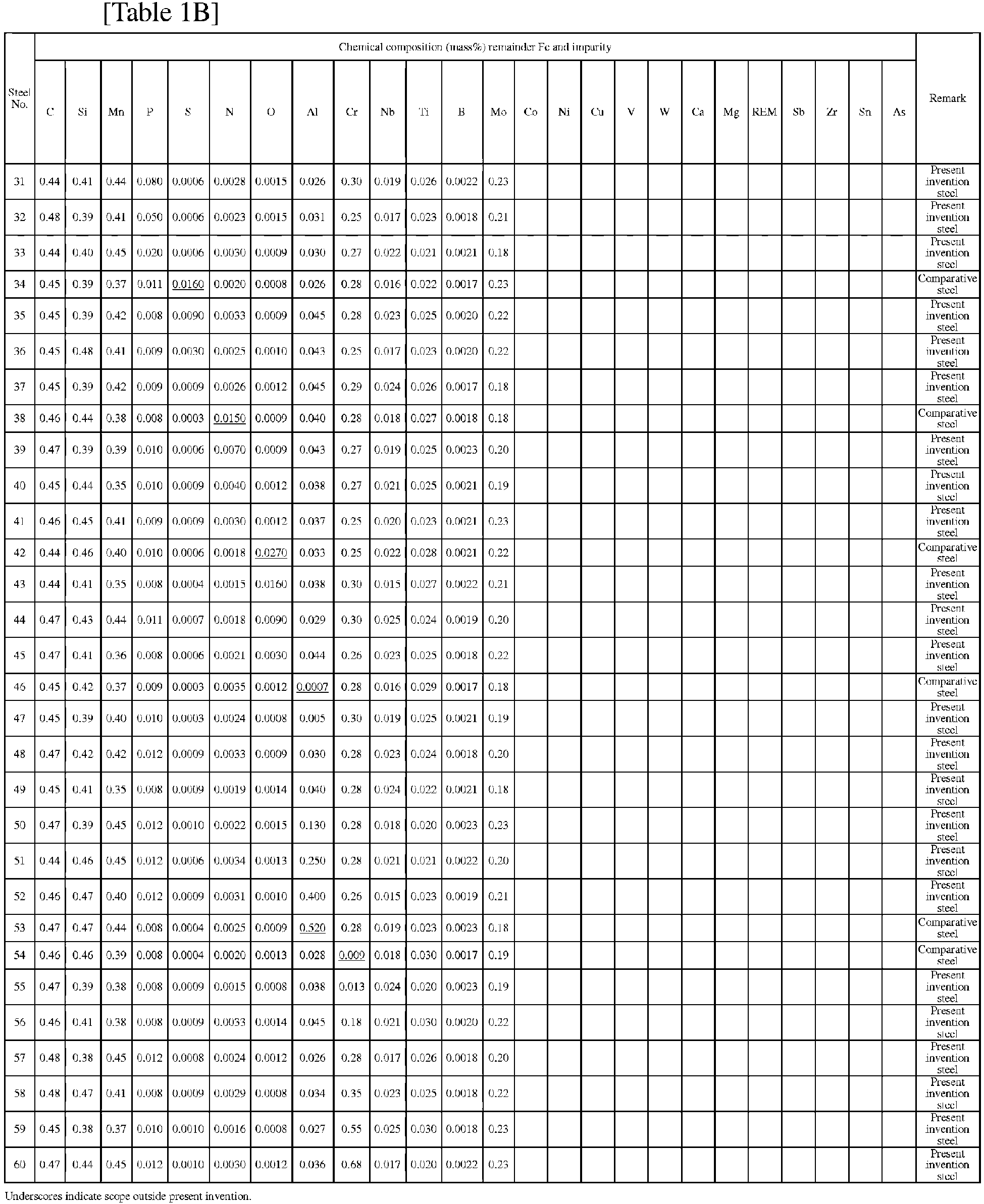


[Table 2A] Steel sheet No. Steel No. Finish rolling Coiling Steel sheet for hot stamping Remark Rolling temperature of rolling one pass before final pass (°C) Rolling reduction of rolling one pass before final pass (%) Rolling temperature of final pass (°C) Final rolling reduction (%) Coiling temperature (°C) Pole density (-) Number proportion of ferrite containing carbide (%) Ferrite (area%) Pearlite (area%) 1 1 971 19 927 18 660 3.4 76 49 51 Present invention example 2 2 975 19 919 17 607 23 74 42 58 Present invention example 3 3 996 19 940 16 586 3.0 84 53 47 Present invention example 4 4 950 23 904 16 577 3.1 61 60 40 Present invention example 5 5 964 20 926 19 552 6.6 40 29 71 Comparative example 6 6 995 23 921 15 638 6.1 44 32 68 Present invention example 7 7 978 21 911 18 554 7.0 48 29 71 Present invention example 8 8 983 22 908 16 569 6.9 45 23 77 Present invention example 9 9 986 22 933 17 565 6.1 44 36 64 Present invention example 10 10 975 19 909 15 638 6.5 40 32 68 Present invention example 11 11 994 21 931 18 570 7.0 47 27 73 Present invention example 12 12 957 19 920 18 636 6.5 44 24 76 Present invention example 13 11 961 21 926 16 587 6.2 42 37 63 Comparative example 14 14 994 21 901 18 639 6.4 47 22 78 Comparative example 15 15 961 20 925 15 626 6.7 42 24 76 Present invention example 16 16 950 21 911 18 615 67 46 22 78 Present invention example 17 17 970 21 929 17 627 6.1 48 36 64 Present invention example 18 18 952 19 902 18 545 7.0 45 23 77 Present invention example 19 19 958 20 939 15 640 7.0 43 34 66 Present invention example 20 20 975 21 900 15 552 6.5 48 26 74 Present invention example 21 21 984 23 929 19 586 6.9 48 35 65 Comparative example 22 22 962 19 923 16 637 6.5 43 23 77 Comparative example 23 23 957 21 926 17 614 62 49 22 78 Present invention example 24 24 961 23 938 15 579 6.4 40 25 75 Present invention example 25 25 996 22 902 17 542 6.9 48 30 70 Present invention example 26 26 995 23 920 15 633 6.8 41 36 64 Present invention example 27 27 951 23 925 16 592 6.4 49 24 76 Present invention example 28 28 997 23 904 15 590 6.2 46 22 78 Present invention example 29 29 969 21 903 19 554 6.2 49 23 77 Comparative example 30 30 962 22 939 17 594 6.7 40 22 78 Comparative example Underscores indicate scope outside present invention and indicate that manufacturing conditions are not preferable. [Table 2B] Steel sheet No. Steel No. Finish rolling Coiling Steel sheet for hot stamping Remark Rolling temperature of rolling one pass before final pass (°C) Rolling reduction of rolling one pass before final pass (%) Rolling temperature of final pass (°C) Final rolling reduction (%) Coiling temperature (°C) Pole density (-) Number proportion of ferrite containing carbide (%) Ferrite (area%) Pearlite (area%) 31 31 969 22 932 15 608 6.7 44 38 62 Present invention example 32 32 978 21 919 18 605 6.3 49 36 64 Present invention example 33 33 1000 23 941 19 595 6.1 45 39 61 Present invention example 34 34 971 22 944 17 541 6.1 42 21 79 Comparative example 35 35 987 21 931 15 580 6.6 40 21 79 Present invention example 36 36 967 19 919 17 653 6.4 47 28 72 Present invention example 37 37 975 20 903 18 556 6.5 40 21 79 Present invention example 38 38 982 20 932 15 561 7.0 43 38 62 Comparative example 39 39 955 19 914 17 580 6.8 41 32 68 Present invention example 40 40 996 20 932 19 587 6.6 46 25 75 Present invention example 41 41 962 19 929 18 545 6.9 40 39 61 Present invention example 42 42 961 22 900 16 557 6.2 44 28 72 Comparative example 43 43 994 21 915 19 578 6.6 47 38 62 Present invention example 44 44 999 22 901 17 580 6.4 44 23 77 Present invention example 45 45 972 21 934 19 615 7.0 46 26 74 Present invention example 46 46 994 19 920 16 652 6.3 48 21 79 Comparative example 47 47 998 23 911 is 638 6.3 47 28 72 Present invention example 48 48 966 20 930 19 600 6.4 41 26 74 Present invention example 49 49 950 22 908 19 561 6.7 44 26 74 Present invention example 50 50 953 22 904 17 563 6.3 48 25 75 Present invention example 51 51 972 21 920 19 645 6.2 44 37 63 Present invention example 52 52 975 20 926 15 592 6.1 48 30 70 Present invention example 53 53 980 20 928 is 617 6.9 49 23 77 Comparative example 54 54 991 23 937 18 552 6.9 41 24 76 Comparative example 55 55 955 22 916 18 556 6.6 41 30 70 Present invention example 56 56 971 21 928 18 630 7.0 41 21 79 Present invention example 57 57 963 19 944 19 621 6.8 44 38 62 Present invention example 58 58 983 23 924 16 551 6.6 48 34 66 Present invention example 59 59 990 23 906 19 544 6.9 41 35 65 Present invention example 60 60 997 19 926 17 541 6.8 44 21 79 Present invention example Underscores indicate scope outside present invention and indicate that manufacturing conditions are not preferable. [Table 2C] Steel sheet No. Steel No. Finish rolling Coiling Steel sheet for hot stamping Remark Rolling temperature of rolling one pass before final pass (°C) Rolling reduction of rolling one pass before final pass (%) Rolling temperature of final pass (°C) Final rolling reduction (%) Coiling temperature (°C) Pole density (-) Number proportion of ferrite containing carbide (%) Ferrite (area%) Pearlite (area%) 61 61 976 22 912 15 558 6.5 41 32 68 Comparative example 62 62 981 22 929 18 596 6.8 46 29 71 Comparative example 63 63 951 20 934 19 655 6.8 42 31 69 Present invention example 64 64 973 22 929 16 583 6.2 43 27 73 Present invention example 65 65 953 23 914 15 586 6.7 47 22 78 Present invention example 66 66 987 23 910 15 653 6.8 48 31 69 Comparative example 67 67 981 19 921 19 573 6.2 44 38 62 Present invention example 68 68 970 19 937 16 660 6.1 48 36 64 Present invention example 69 69 976 20 925 16 562 6.5 46 25 75 Present invention example 70 70 968 22 924 19 545 6.2 47 34 66 Comparative example 71 71 969 22 910 19 621 7.0 41 25 75 Present invention example 72 72 970 23 945 17 568 6.6 49 34 66 Present invention example 73 73 955 22 903 18 548 6.1 41 23 77 Present invention example 74 74 990 20 945 15 625 7.0 48 38 62 Comparative example 75 75 964 19 903 19 649 6.8 46 35 65 Present invention example 76 76 987 23 919 19 589 63 40 28 72 Present invention example 77 77 957 23 903 18 587 6.7 44 34 66 Present invention example 78 78 979 23 909 16 651 6.1 44 22 78 Comparative example 79 79 950 21 916 18 604 6.1 49 27 73 Present invention example 80 80 994 20 937 15 634 6.7 40 33 67 Present invention example 81 81 983 22 942 19 551 63 43 36 64 Present invention example 82 82 982 19 930 17 572 6.2 46 29 71 Comparative example 83 83 965 19 907 16 644 6.7 48 36 64 Present invention example 84 84 979 23 935 17 578 7.0 49 31 69 Present invention example 85 85 998 20 907 18 597 6.8 47 28 72 Comparative example 86 86 994 19 922 15 584 6.8 40 34 66 Present invention example 87 87 992 23 910 18 568 6.2 49 37 63 Present invention example 88 88 987 19 929 17 577 6.7 41 21 79 Comparative example 89 89 967 19 926 16 605 7.0 45 30 70 Present invention example 90 90 961 19 901 18 567 6.6 42 28 72 Present invention example Underscores indicate scope outside present invention and indicate that manufacturing conditions are not preferable. [Table 2D] Steel sheet No. Steel No. Finish rolling Coiling Steel sheet for hot stamping Remark Rolling temperature of rolling one pass before final pass (°C) Rolling reduction of rolling one pass before final pass (%) Rolling temperature of final pass (°C) Final rolling reduction (%) Coiling temperature (°C) Pole density (-) Number proportion of ferrite containing carbide (%) Ferrite (area%) Pearlite (area%) 91 21 977 19 938 19 646 63 47 39 61 Comparative example 92 92 996 19 927 19 635 6.1 47 30 70 Present invention example 93 93 954 20 915 15 571 6.1 41 34 66 Present invention example 94 94 972 23 916 18 541 6.1 40 32 68 Comparative example 95 95 956 23 933 16 545 7.0 42 26 74 Present invention example 96 96 988 23 917 15 612 7.0 44 34 66 Present invention example 97 97 961 23 937 15 583 7.0 44 21 79 Comparative example 98 98 973 23 929 is 627 6.6 42 23 77 Present invention example 99 99 996 21 918 16 541 6.6 45 25 75 Present invention example 100 100 951 19 927 19 549 6.2 42 22 78 Comparative example 101 101 978 22 909 18 643 6.6 45 22 78 Present invention example 102 102 985 23 910 17 646 6.8 45 28 72 Present invention example 103 103 962 20 917 17 544 6.7 48 29 71 Comparative example 104 104 994 22 905 19 602 6.7 46 28 72 Present invention example 105 105 953 21 927 18 655 6.4 48 25 75 Present invention example 106 106 962 19 903 19 551 6.9 48 24 76 Comparative example 107 107 954 20 922 15 628 6.4 46 21 79 Present invention example 108 108 971 22 935 19 627 6.9 47 25 75 Present invention example 109 2 1061 22 908 17 643 3.5 42 5 95 Comparative example 110 2 1050 22 939 15 617 2.2 40 14 86 Present invention example 111 2 1029 23 910 19 568 2.9 43 23 77 Present invention example 112 2 1012 21 903 16 573 5.6 43 22 78 Present invention example 113 2 972 19 942 15 613 6.5 44 38 62 Present invention example 114 2 936 19 927 17 610 6.2 46 32 68 Present invention example 115 2 918 22 900 15 593 6.6 48 28 72 Present invention example 116 2 908 22 923 18 631 8.3 49 22 78 Present invention example 117 2 871 19 917 15 545 11.0 47 33 67 Comparative example 118 2 983 36 942 18 601 12.0 43 23 77 Comparative example 119 2 982 23 939 16 639 8.1 48 38 62 Present invention example 120 2 986 19 922 16 637 4.0 48 28 72 Present invention example Underscores indicate scope outside present invention and indicate that manufacturing conditions are not preferable. [Table 2E] Steel sheet No. Steel No. Finish rolling Coiling Steel sheet for hot stamping Remark Rolling temperature of rolling one pass before final pass (°C) Rolling reduction of rolling one pass before final pass (%) Rolling temperature of final pass (°C) Final rolling reduction (%) Coiling temperature (°C) Pole density (-) Number proportion of ferrite containing carbide (%) Ferrite (area%) Pearlite (area%) 121 2 973 17 931 16 551 5.6 43 29 71 Present invention example 122 2 978 14 906 17 543 7.0 41 23 77 Present invention example 123 2 997 11 911 16 626 8.2 49 22 78 Present invention example 124 2 958 6 921 15 627 13.0 45 22 78 Comparative example 125 2 1000 21 1016 16 571 6.7 47 8 92 Comparative example 126 2 986 23 989 17 654 6.4 45 20 80 Present invention example 127 2 966 23 972 15 546 6.8 40 39 61 Present invention example 128 2 956 21 879 19 602 6.4 48 30 70 Present invention example 129 2 962 22 904 18 545 6.1 47 51 49 Present invention example 130 2 993 20 951 19 624 6.5 48 65 35 Present invention example 131 2 978 23 863 18 625 6.9 43 69 31 Present invention example 132 2 950 21 854 16 647 6.5 41 88 12 Present invention example 133 2 952 23 842 16 559 6.7 40 95 5 Comparative example 134 2 972 19 900 18 635 7.0 89 29 71 Present invention example 135 2 953 23 925 16 626 6.6 83 32 68 Present invention example 136 2 981 21 904 12 598 7.0 67 28 72 Present invention example 137 2 950 19 937 10 636 6.3 51 26 74 Present invention example 138 2 967 23 900 8 606 6.2 43 23 77 Present invention example 139 2 951 20 913 6 658 6.2 23 30 70 Present invention example 140 2 972 19 928 4 605 6.8 5 25 75 Comparative example 141 2 982 21 918 17 775 6.6 44 3 97 Comparative example 142 2 991 20 939 17 742 7.0 49 16 84 Present invention example 143 2 966 23 901 18 679 6.2 47 37 63 Present invention example 144 2 979 23 903 18 639 6.5 49 47 53 Present invention example 145 2 951 23 931 15 569 6.6 46 56 44 Present invention example 146 2 980 21 924 15 470 6.8 41 68 32 Present invention example 147 2 989 21 936 15 406 6.7 49 81 19 Present invention example 148 2 969 19 913 15 366 7.0 47 21 9 Comparative example 149 2 970 23 907 16 590 6.5 42 21 79 Present invention example 150 2 987 20 933 19 573 6.6 49 30 70 Present invention example Underscores indicate scope outside present invention and indicate that manufacturing conditions are not preferable. [Table 2F] Steel sheet No. Steel No. Finish rolling Coiling Steel sheet for hot stamping Remark Rolling temperature of rolling one pass before final pass (°C) Rolling reduction of rolling one pass before final pass (%) Rolling temperature of final pass (°C) Final rolling reduction (%) Coiling temperature (°C) Pole density (-) Number proportion of ferrite containing carbide (%) Ferrite (area%) Pearlite (area%) 151 2 966 21 927 17 577 63 44 27 73 Present invention example 152 2 967 22 940 18 562 6.1 41 38 62 Present invention example 153 2 988 23 905 19 605 6.4 44 28 72 Present invention example 154 2 977 19 944 18 650 6.5 47 37 63 Present invention example 155 2 990 23 938 16 571 6.3 49 34 66 Present invention example 156 2 956 21 906 17 649 6.8 41 27 73 Present invention example 157 2 963 22 931 15 580 7.0 41 33 67 Present invention example 158 2 985 20 930 19 659 6.8 41 29 71 Present invention example 159 2 973 23 907 16 577 7.0 42 33 67 Present invention example 160 2 950 20 932 15 634 6.9 45 39 61 Present invention example 161 2 981 20 940 15 649 6.6 40 35 65 Present invention example 162 2 981 20 925 19 596 6.1 46 29 71 Present invention example 163 2 968 21 940 15 605 6.1 44 29 71 Present invention example 164 2 974 23 937 16 597 6.4 48 39 61 Present invention example 165 2 999 20 937 17 576 6.5 49 27 73 Present invention example 166 2 960 22 900 18 566 6.9 43 35 65 Present invention example 167 2 970 20 911 18 549 6.5 41 27 73 Present invention example 168 2 999 23 942 19 631 6.2 42 30 70 Present invention example 169 2 970 20 942 16 630 6.8 46 24 76 Present invention example 170 2 964 22 925 16 563 6.3 48 38 62 Present invention example 171 2 992 20 930 16 651 6.9 43 31 69 Present invention example 172 2 953 19 943 16 625 6.5 41 34 66 Present invention example 173 2 989 20 932 15 636 6.2 47 33 67 Present invention example 174 2 977 21 904 16 652 6.1 44 36 64 Present invention example 175 2 981 21 936 19 655 7.0 42 37 63 Present invention example 176 2 989 19 900 18 573 6.7 43 38 62 Present invention example 177 2 966 20 933 16 632 6.8 45 38 62 Present invention example 178 2 991 22 905 19 584 6.8 44 37 63 Present invention example 179 2 951 22 941 is 625 6.7 45 37 63 Present invention example 180 2 999 19 933 16 561 6.9 45 39 61 Present invention example Underscores indicate scope outside present invention and indicate that manufacturing conditions are not preferable. [Table 2G] Steel sheet No. Steel No. Finish rolling Coiling Steel sheet for hot stamping Remark Rolling temperature of rolling one pass before final pass (°C) Rolling reduction of rolling one pass before final pass (%) Rolling temperature of final pass (°C) Final rolling reduction (%) Coiling temperature (°C) Pole density (-) Number proportion of ferrite containing carbide (%) Ferrite (area%) Pearlite (area%) 181 2 986 19 902 15 606 7.0 46 24 76 Present invention example 182 2 996 20 907 19 614 6.6 42 39 61 Present invention example 183 2 976 19 904 18 595 6.3 45 38 62 Present invention example 184 2 999 20 909 19 632 6.5 49 23 77 Present invention example 185 2 962 21 939 17 641 7.0 44 38 62 Present invention example 186 2 954 20 938 19 648 6.3 47 34 66 Present invention example 187 2 960 21 906 16 592 6.4 41 29 71 Present invention example 188 2 978 21 932 18 548 6.2 47 32 68 Present invention example 189 109 989 22 925 16 651 7.0 44 36 64 Present invention example 190 110 966 21 933 18 573 6.6 46 32 68 Present invention example 191 111 985 19 926 19 606 6.3 41 37 63 Present invention example 192 112 981 20 930 18 620 6.9 50 26 74 Present invention example 193 113 971 22 931 19 629 6.8 47 24 76 Present invention example 194 114 951 19 915 17 581 6.7 44 31 69 Present invention example 195* 115 962 20 911 18 623 12.0 45 24 76 Comparative example Underscores indicate scope outside present invention and indicate that manufacturing conditions are not preferable. [Table 3A] Manufacturing No. Steel sheet No. Steel No. Hot stamping Hot-stamping formed body Remark Heating rate (°C/s) Heating temperature (°C) Holding time (minutes) Cooling rate (°C/s) Average grain size of prior γ grains (µm) Standard deviation of grain sizes of prior γ grains (µm) Prior γ grains having average grain size of 0.5 to 3.0 µm (area%) Tensile strength (MPa) Maximum bending angle (°) 1 1 1 6 896 4.5 445 8 0.3 35 2550 36 Present invention example 2 2 2 5 897 4.4 238 5 0.3 39 2550 32 Present invention example 3 3 3 8 914 4.1 257 7 0.4 39 2583 48 Present invention example 4 4 4 6 891 4.4 489 7 0.3 35 2626 32 Present invention example 5 5 5 8 920 4.8 291 10 0.6 40 2167 46 Comparative example 6 6 6 9 916 4.0 347 10 0.5 41 2439 46 Present invention example 7 7 7 8 915 4.7 430 10 1.1 47 2572 37 Present invention example 8 8 8 7 891 4.0 192 7 0.5 44 2440 32 Present invention example 9 9 9 10 893 4.0 193 8 1.2 48 2569 35 Present invention example 10 10 10 10 915 3.6 368 5 0.9 45 2551 27 Present invention example 11 11 11 7 907 3.7 487 9 1.0 45 2578 25 Present invention example 12 12 12 7 901 5.0 351 5 0.8 41 2636 29 Present invention example 13 13 13 10 907 4.8 284 5 1.0 46 2615 18 Comparative example 14 14 14 8 893 3.9 251 7 1.2 49 2563 19 Comparative example 15 15 15 5 904 4.5 237 6 0.5 41 2597 23 Present invention example 16 16 16 9 899 4.8 212 8 0.8 47 2598 45 Present invention example 17 17 17 10 919 4.4 216 9 0.9 48 2577 43 Present invention example 18 18 18 9 899 4.2 163 10 0.7 41 2558 47 Present invention example 19 19 19 5 892 4.6 413 6 1.2 41 2580 34 Present invention example 20 20 20 9 895 4.7 366 9 0.5 47 2570 23 Present invention example 21 21 21 10 905 4.5 334 9 0.6 49 2583 19 Comparative example 22 22 22 5 912 4.5 392 8 0.9 42 2090 42 Comparative example 23 23 23 7 906 4.9 223 5 1.1 43 2466 45 Present invention example 24 24 24 7 891 4.6 430 10 0.6 42 2595 44 Present invention example 25 25 25 10 899 3.8 310 10 1.1 47 2573 43 Present invention example 26 26 26 6 911 3.6 486 7 1.2 47 2609 39 Present invention example 27 27 27 7 903 5.0 293 7 1.0 44 2621 34 Present invention example 28 28 28 7 904 4.2 358 5 0.7 48 2633 28 Present invention example 29 29 29 7 892 3.6 358 5 0.9 41 2625 14 Comparative example 30 30 30 7 890 4.1 178 8 0.6 42 2577 12 Comparative example Underscores indicate scope outside present invention and indicate that manufacturing conditions are not preferable. [Table 3B] Manufacturing No. Steel sheet No. Steel No. Hot stamping Hot-stamping formed body Remark Heating rate (°C/s) Heating temperature (°C) Holding time (minutes) Cooling rate (°C/s) Average grain size of prior γ grains (µm) Standard deviation of grain sizes of prior γ grains (µm) Prior γ grains having average grain size of 0.5 to 3.0 µm (area%) Tensile strength (MPa) Maximum bending angle (°) 31 31 31 10 915 4.3 342 7 1.2 46 2589 25 Present invention example 32 32 32 9 905 3.8 481 6 1.1 49 2562 37 Present invention example 33 33 33 8 904 4.9 226 6 0.6 43 2565 48 Present invention example 34 34 34 5 918 4.4 242 5 0.8 49 2571 14 Comparative example 35 35 35 5 900 4.8 306 7 0.5 43 2568 25 Present invention example 36 36 36 9 908 4.5 194 8 0.8 45 2579 38 Present invention example 37 37 37 8 901 4.4 484 6 0.8 41 2571 43 Present invention example 38 38 38 7 906 4.1 244 9 0.9 48 2556 19 Comparative example 39 39 39 7 902 4.9 319 5 0.6 43 2582 24 Present invention example 40 40 40 8 899 3.9 467 9 0.9 40 2579 35 Present invention example 41 41 41 8 905 4.8 374 6 0.9 44 2578 45 Present invention example 42 42 42 8 892 5.0 344 10 1.2 47 2581 19 Comparative example 43 43 43 8 899 4.4 360 7 1.0 48 2586 30 Present invention example 44 44 44 7 911 4.5 422 6 0.9 41 2575 34 Present invention example 45 45 45 8 906 4.9 223 6 0.6 48 2558 48 Present invention example 46 46 46 10 892 4.5 456 5 1.1 48 2582 18 Comparative example 47 47 47 7 902 4.8 460 8 1.0 49 2560 30 Present invention example 48 48 48 6 901 3.6 407 8 1.2 42 2588 45 Present invention example 49 49 49 7 898 4.0 271 7 1.1 45 2560 47 Present invention example 50 50 50 5 911 4.3 456 7 1.0 41 2575 43 Present invention example 51 51 51 9 899 4.5 278 9 0.7 41 2582 39 Present invention example 52 52 52 10 898 5.0 210 8 1.0 41 2553 28 Present invention example 53 53 53 9 891 3.6 390 9 0.8 41 2567 18 Comparative example 54 54 54 9 906 4.6 491 10 1.1 48 2027 48 Comparative example 55 55 55 7 901 3.9 441 8 0.6 47 2409 44 Present invention example 56 56 56 5 915 4.9 338 8 0.9 42 2597 48 Present invention example 57 57 57 7 919 4.4 418 8 0.5 43 2560 46 Present invention example 58 58 58 6 907 4.0 429 10 1.0 47 2615 36 Present invention example 59 59 59 9 918 4.5 444 9 0.9 48 2605 39 Present invention example 60 60 60 9 905 3.6 426 10 0.9 47 2619 30 Present invention example Underscores indicate scope outside present invention and indicate that manufacturing conditions are not preferable. [Table 3C] Manufacturing No. Steel sheet No. Steel No. Hot stamping Hot-stamping formed body Remark Heating rate (°C/s) Heating temperature (°C) Holding time (minutes) Cooling rate (°C/s) Average grain size of prior γ grains (µm) Standard deviation of grain sizes of prior γ grains (µm) Prior γ grains having average grain size of 0.5 to 3.0 µm (area%) Tensile strength (MPa) Maximum bending angle (°) 61 61 61 7 897 3.6 357 6 1.1 40 2640 15 Comparative example 62 62 62 10 918 4.3 321 7 0.6 46 2601 15 Comparative example 63 63 63 7 890 4.6 247 6 1.1 47 2636 22 Present invention example 64 64 64 5 917 4.9 357 7 0.9 41 2632 37 Present invention example 65 65 65 9 893 3.9 234 6 0.7 46 2415 38 Present invention example 66 66 66 10 901 4.8 263 10 1.1 48 2610 19 Comparative example 67 67 67 9 916 4.2 256 9 1.2 47 2643 27 Present invention example 68 68 68 10 910 4.4 271 7 0.5 46 2608 35 Present invention example 69 69 69 8 902 4.4 169 5 1.2 42 2466 36 Present invention example 70 70 20 5 904 4.8 412 7 1.2 47 2647 12 Comparative example 71 71 71 10 897 3.9 290 7 0.8 49 2617 21 Present invention example 72 72 72 6 918 4.8 384 6 0.9 41 2646 40 Present invention example 73 73 73 7 899 4.6 284 6 1.1 45 2521 32 Present invention example 74 74 74 5 906 4.7 342 7 0.5 46 2629 12 Comparative example 75 75 75 5 913 4.6 482 5 1.0 42 2612 26 Present invention example 76 76 76 5 918 4.7 230 5 0.7 48 2626 36 Present invention example 77 77 77 8 909 4.0 410 5 0.8 42 2635 36 Present invention example 78 78 78 8 890 5.0 492 10 0.5 43 2639 12 Comparative example 79 79 79 9 900 4.0 457 5 1.2 48 2622 24 Present invention example 80 80 80 10 894 3.6 305 7 0.5 47 2637 40 Present invention example 81 81 81 8 908 4.1 373 8 0.5 48 2614 39 Present invention example 82 82 82 5 918 4.2 437 10 0.7 41 2628 15 Comparative example 83 83 83 6 907 4.6 377 6 0.7 49 2605 24 Present invention example 84 84 84 5 918 4.5 283 9 0.5 47 2613 31 Present invention example 85 85 85 7 898 4.2 404 7 0.9 46 2643 16 Comparative example 86 86 86 5 891 3.8 271 10 1.2 41 2619 27 Present invention example 87 87 87 6 912 3.6 289 5 0.6 44 2631 40 Present invention example 88 88 88 10 916 3.9 396 8 0.7 40 2601 14 Comparative example 89 89 89 8 909 4.3 357 5 0.8 44 2647 25 Present invention example 90 90 90 8 895 3.5 335 8 0.5 46 2603 36 Present invention example Underscores indicate scope outside present invention and indicate that manufacturing conditions are not preferable. [Table 3D] Manufacturing No. Steel sheet No. Steel No. Hot stamping Hot-stamping formed body Remark Heating rate (°C/s) Heating temperature (°C) Holding time (minutes) Cooling rate (°C/s) Average grain size of prior γ grains (µm) Standard deviation of grain sizes of prior γ grains (µm) Prior γ grains having average grain size of 0.5 to 3.0 µm (area%) Tensile strength (MPa) Maximum bending angle (°) 91 91 21 10 900 3.9 332 7 1.2 49 2603 14 Comparative example 92 92 92 7 892 4.8 302 9 0.5 49 2629 25 Present invention example 93 93 93 7 902 4.9 258 7 0.5 41 2607 38 Present invention example 94 94 94 6 893 4.0 357 8 1.0 44 2601 16 Comparative example 95 95 95 9 900 4.5 390 8 0.6 40 2613 29 Present invention example 96 96 96 6 893 5.0 319 8 1.2 45 2644 32 Present invention example 97 97 97 9 890 4.0 250 10 0.5 45 2608 11 Comparative example 98 98 98 9 908 4.3 343 6 1.0 42 2612 23 Present invention example 99 99 99 8 902 4.7 154 9 1.2 44 2606 40 Present invention example 100 100 100 7 898 3.8 159 5 1.0 45 2610 17 Comparative example 101 101 101 9 909 4.5 489 7 0.5 41 2605 30 Present invention example 102 102 102 10 902 3.8 435 6 0.6 44 2605 39 Present invention example 103 103 103 7 893 4.6 493 10 1.2 45 2648 12 Comparative example 104 104 104 10 913 4.2 349 9 0.5 45 2638 27 Present invention example 105 105 105 6 908 3.5 266 10 0.5 43 2636 34 Present invention example 106 106 106 5 908 4.6 241 10 0.9 49 2618 15 Comparative example 107 107 107 10 920 3.8 302 5 0.5 47 2602 30 Present invention example 108 108 108 10 893 3.7 242 8 0.8 48 2640 38 Present invention example 109 109 2 5 891 4.2 222 9 2.4 46 2595 17 Comparative example 110 110 2 7 890 4.8 231 8 0.6 45 2551 21 Present invention example 111 111 2 6 891 3.8 249 6 1.2 46 2572 31 Present invention example 112 112 2 10 897 4.8 436 18 0.8 42 2562 38 Present invention example 113 113 2 10 897 4.5 407 14 0.9 40 2556 32 Present invention example 114 114 2 10 898 4.2 387 13 1.1 44 2575 37 Present invention example 115 115 2 7 914 4.9 402 18 1.1 40 2597 31 Present invention example 116 116 2 8 897 5.0 360 22 0.6 47 2594 29 Present invention example 117 117 2 6 910 43 363 34 0.9 48 2588 16 Comparative example 118 118 2 9 919 3.6 371 3 0.9 46 2560 11 Comparative example 119 119 2 10 908 4.7 258 23 0.8 46 2558 32 Present invention example 120 120 2 8 894 4.6 424 7 1.0 45 2588 48 Present invention example Underscores indicate scope outside present invention and indicate that manufacturing conditions are not preferable. [Table 3E] Manufacturing No. Steel sheet No. Steel No. Hot stamping Hot-stamping formed body Remark Heating rate (°C/s) Heating temperature (°C) Holding time (minutes) Cooling rate (°C/s) Average grain size of prior γ grains (µm) Standard deviation of grain sizes of prior γ grains (µm) Prior γ grains having average grain size of 0.5 to 3.0 µm (area%) Tensile strength (MPa) Maximum bending angle (°) 121 121 2 6 890 3.6 408 20 0.6 48 2586 34 Present invention example 122 122 2 6 920 4.1 494 15 0.5 44 2580 33 Present invention example 123 123 2 7 919 3.7 361 25 0.7 49 2556 30 Present invention example 124 124 2 6 909 4.5 387 3 0.9 44 2581 17 Comparative example 125 125 2 7 913 4.0 399 13 3.2 85 2560 16 Comparative example 126 126 2 6 900 3.8 162 20 13 57 2592 24 Present invention example 127 127 2 6 914 4.4 414 18 0.6 47 2576 40 Present invention example 128 128 2 10 911 3.9 181 17 0.9 48 2595 34 Present invention example 129 129 2 6 897 3.8 193 17 0.3 35 2596 42 Present invention example 130 130 2 7 903 4.4 217 12 0.7 43 2595 40 Present invention example 131 131 2 6 903 4.1 392 13 1.0 47 2591 36 Present invention example 132 132 2 10 894 4.4 265 12 1.5 55 2553 26 Present invention example 133 133 2 5 918 3.7 246 38 3.0 66 2564 12 Comparative example 134 134 2 9 908 4.1 384 6 0.4 32 2596 45 Present invention example 135 135 2 9 891 4.5 483 9 0.3 32 2579 47 Present invention example 136 136 2 9 892 3.5 251 10 0.4 31 2568 48 Present invention example 137 137 2 8 919 3.9 477 10 0.3 32 2567 48 Present invention example 138 138 2 9 913 4.4 446 9 0.8 41 2588 34 Present invention example 139 139 2 10 900 4.6 467 9 1.6 55 2554 27 Present invention example 140 140 2 8 914 3.5 233 10 24 71 2556 14 Comparative example 141 141 2 5 896 4.9 273 17 2.3 65 2587 13 Comparative example 142 142 2 9 898 3.8 298 18 1.6 56 2569 30 Present invention example 143 143 2 5 912 5.0 293 18 0.6 45 2571 38 Present invention example 144 144 2 9 890 3.8 383 15 0.3 39 2599 45 Present invention example 145 145 2 9 903 3.8 295 12 0.2 36 2582 45 Present invention example 146 146 2 5 901 4.8 347 19 0.9 42 2580 40 Present invention example 147 147 2 10 895 4.7 383 16 1.5 54 2578 30 Present invention example 148 148 2 6 904 5.0 498 11 3.2 73 2574 18 Comparative example 149 149 2 9 894 4.1 484 10 1.0 44 2564 37 Present invention example 150 150 2 10 896 3.5 361 6 0.6 42 2556 36 Present invention example Underscores indicate scope outside present invention and indicate that manufacturing conditions are not preferable. [Table 3F] Manufacturing No. Steel sheet No. Steel No. Hot stamping Hot-stamping formed body Remark Heating rate (°C/s) Heating temperature (°C) Holding time (minutes) Cooling rate (°C/s) Average grain size of prior γ grains (µm) Standard deviation of grain sizes of prior γ grains (µm) Prior γ grains having average grain size of 0.5 to 3.0 µm (area%) Tensile strength (MPa) Maximum bending angle (°) 151 151 2 10 895 4.6 434 9 0.7 47 2563 32 Present invention example 152 152 2 10 920 4.6 247 9 0.5 43 2580 33 Present invention example 153 153 2 7 902 4.6 333 6 1.1 49 2584 36 Present invention example 154 154 2 6 898 4.1 244 8 0.8 41 2575 36 Present invention example 155 155 2 10 891 3.8 169 6 0.9 45 2569 36 Present invention example 156 156 2 8 900 4.3 354 7 0.7 48 2560 36 Present invention example 157 157 2 7 901 4.0 439 6 0.9 45 2573 33 Present invention example 158 158 2 10 906 3.5 331 5 1.2 41 2586 35 Present invention example 159 159 2 955 902 4.9 256 8 0.6 48 2636 32 Present invention example 160 160 2 498 893 3.6 324 8 1.1 45 2611 37 Present invention example 161 161 2 126 913 3.7 392 6 1.0 46 2588 36 Present invention example 162 162 2 47 917 3.5 327 9 0.7 45 2583 32 Present invention example 163 163 2 11 894 3.5 461 5 0.8 42 2560 33 Present invention example 164 164 2 3 909 4.3 314 6 0.5 44 2545 31 Present invention example 165 165 2 0.6 907 3.5 436 9 1.1 41 1976 35 Comparative example 166 166 2 7 1031 3.6 336 7 0.9 44 2187 31 Comparative example 167 167 2 5 994 3.9 160 7 0.6 48 2533 41 Present invention example 168 168 2 7 969 4.5 383 5 1.0 48 2585 49 Present invention example 169 169 2 5 931 4.9 347 6 1.2 41 2576 44 Present invention example 170 170 2 7 904 4.8 364 7 0.7 40 2577 42 Present invention example 171 171 2 6 873 3.5 484 7 1.1 42 2567 43 Present invention example 172 172 2 6 829 4.9 323 5 0.7 40 2554 40 Present invention example 173 173 2 10 811 4.8 439 7 0.8 44 2580 24 Present invention example 174 174 2 7 908 120 191 9 0.8 46 2188 46 Comparative example 175 175 2 9 897 8.1 406 5 0.9 41 2516 48 Present invention example 176 176 2 8 909 7.4 434 10 0.8 40 2565 44 Present invention example 177 177 2 7 904 6.1 469 10 1.1 40 2618 43 Present invention example 178 178 2 10 917 4.4 358 6 1.1 46 2639 46 Present invention example 179 179 2 8 901 2.6 151 10 0.5 46 2589 35 Present invention example 180 180 2 6 896 1.2 411 5 0.6 49 2574 30 Present invention example Underscores indicate scope outside present invention and indicate that manufacturing conditions are not preferable. [Table 3G] Manufacturing No. Steel sheet No. Steel No. Hot stamping Hot-stamping formed body Remark Heating rate (°C/s) Heating temperature (°C) Holding time (minutes) Cooling rate (°C/s) Average grain size of prior γ grains (µm) Standard deviation of grain sizes of prior γ grains (µm) Prior γ grains having average grain size of 0.5 to 3.0 µm (area%) Tensile strength (MPa) Maximum bending angle (°) 181 181 2 5 918 4.0 985 9 1.0 49 2606 34 Present invention example 182 182 2 8 920 4.5 561 8 1.1 45 2616 34 Present invention example 183 183 2 8 903 4.2 117 9 0.7 40 2594 38 Present invention example 184 184 2 8 893 4.3 19 7 0.7 41 2483 33 Present invention example 185 185 2 5 895 4.9 3 10 0.6 46 2167 34 Comparative example 186 186 2 7 916 4.7 208 8 0.9 45 2563 31 Present invention example 187 187 2 7 910 3.6 151 9 0.5 43 2576 40 Present invention example 188 188 2 6 891 4.0 182 9 3.1 65 2581 18 Comparative example 189 189 109 7 904 4.9 368 6 1.7 71 2620 31 Present invention example 190 190 110 9 903 4.8 251 6 1.6 77 2609 32 Present invention example 191 191 111 10 909 3.5 366 8 1.9 78 2611 35 Present invention example 192 192 112 11 891 3.5 241 8 0.9 50 2611 39 Present invention example 193 193 113 10 895 3.7 239 7 0.8 48 2640 38 Present invention example 194 194 114 7 900 4.8 314 5 0.6 42 2588 25 Present invention example 195 195* 115 7 904 4.4 381 3 0.8 45 2579 17 Comparative example Underscores indicate scope outside present invention and indicate that manufacturing conditions are not preferable. - From Table 3A to Table 3G, it is found that the hot-stamping formed bodies according to the examples of the present invention have high strength and excellent bendability. Meanwhile, it can be seen that in the hot-stamping formed bodies according to comparative examples, one of the properties deteriorated.
- According to the above-described aspects of the present invention, it is possible to provide a hot-stamping formed body having high strength and excellent bendability, and a steel sheet for hot stamping capable of manufacturing this hot-stamping formed body.
Claims (5)
- A steel sheet for hot stamping consisting of, as a chemical composition, by mass%:C: more than 0.40% and 0.70% or less;Si: 0.010% to 1.30%;Mn: 0.10% to 0.60%;P: 0.100% or less;S: 0.0100% or less;N: 0.0140% or less;0: 0.0200% or less;Al: 0.0010% to 0.500%;Cr: 0.010% to 0.80%;Nb: 0% to 0.100%;Ti: 0% to 0.100%;B: 0% to 0.0100%;Mo: 0% to 1.00%;Co: 0% to 2.00%;Ni: 0% or more and less than 3.00%;Cu: 0% to 1.00%;V: 0% to 1.00%;W: 0% to 1.000%;Ca: 0% to 0.010%;Mg: 0% to 1.000%;REM: 0% to 1.000%;Sb: 0% to 1.000%;Zr: 0% to 1.000%;Sn: 0% to 1.000%;As: 0% to 0.100%; anda remainder of Fe and impurities,wherein the steel sheet for hot stamping has a microstructure in which an average value of pole densities of ferrite in an orientation group consisting of {100}<011> to {223}<110> is 10.0 or less,in entire ferrite, a number proportion of ferrite containing a carbide having an equivalent circle diameter of 0.2 µm or more in grains is 20% or more, andan area ratio of pearlite is 10% to 90% and an area ratio of ferrite is 10% to 90%.
- The steel sheet for hot stamping according to claim 1, wherein the steel sheet for hot stamping contains, as the chemical composition, by mass%, one or more selected from the group consisting of:Nb: 0.001% to 0.100%,Ti: 0.010% to 0.100%,B: 0.0015% to 0.0100%,Mo: 0.05% to 1.00%,Co: 0.05% to 2.00%,Ni: 0.01% or more and less than 3.00%,Cu: 0.01% to 1.00%,V: 0.01% to 1.00%,W: 0.001% to 1.000%,Ca: 0.001% to 0.010%,Mg: 0.001% to 1.000%,REM: 0.001% to 1.000%,Sb: 0.005% to 1.000%,Zr: 0.001% to 1.000%,Sn: 0.001% to 1.000%, andAs: 0.001% to 0.100%.
- A hot-stamping formed body consisting of, as a chemical composition, by mass%:C: more than 0.40% and 0.70% or less;Si: 0.010% to 1.30%;Mn: 0.10% to 0.60%;P: 0.100% or less;S: 0.0100% or less;N: 0.0140% or less;O: 0.0200% or less;Al: 0.0010% to 0.500%;Cr: 0.010% to 0.80%;Nb: 0% to 0.100%;Ti: 0% to 0.100%;B: 0% to 0.0100%;Mo: 0% to 1.00%;Co: 0% to 2.00%;Ni: 0% or more and less than 3.00%;Cu: 0% to 1.00%;V: 0% to 1.00%;W: 0% to 1.000%;Ca: 0% to 0.010%;Mg: 0% to 1.000%;REM: 0% to 1.000%;Sb: 0% to 1.000%;Zr: 0% to 1.000%;Sn: 0% to 1.000%;As: 0% to 0.100%; anda remainder of Fe and impurities,wherein the hot-stamping formed body has a microstructure in which an average grain size of prior austenite grains is 5 to 25 µm,a standard deviation of grain sizes of the prior austenite grains is 0.1 to 2.0 µm, anda tensile strength of the hot-stamping formed body is 2,200 MPa or more.
- The hot-stamping formed body according to claim 3, wherein the hot-stamping formed body contains, as the chemical composition, by mass%, one or more selected from the group consisting of:Nb: 0.001% to 0.100%,Ti: 0.010% to 0.100%,B: 0.0015% to 0.0100%,Mo: 0.05% to 1.00%,Co: 0.05% to 2.00%,Ni: 0.01% or more and less than 3.00%,Cu: 0.01% to 1.00%,V: 0.01% to 1.00%,W: 0.001% to 1.000%,Ca: 0.001% to 0.010%,Mg: 0.001% to 1.000%,REM: 0.001% to 1.000%,Sb: 0.005% to 1.000%,Zr: 0.001% to 1.000%,Sn: 0.001% to 1.000%, andAs: 0.001% to 0.100%.
- The hot-stamping formed body according to claim 3 or 4, wherein an area ratio of the prior austenite grains having an average grain size of 0.5 to 3.0 µm is 60% or less.
Applications Claiming Priority (2)
| Application Number | Priority Date | Filing Date | Title |
|---|---|---|---|
| JP2021081621 | 2021-05-13 | ||
| PCT/JP2022/019758 WO2022239758A1 (en) | 2021-05-13 | 2022-05-10 | Steel sheet for hot stamping and hot stamped molded body |
Publications (2)
| Publication Number | Publication Date |
|---|---|
| EP4299769A1 true EP4299769A1 (en) | 2024-01-03 |
| EP4299769A4 EP4299769A4 (en) | 2025-06-04 |
Family
ID=84029634
Family Applications (1)
| Application Number | Title | Priority Date | Filing Date |
|---|---|---|---|
| EP22807458.9A Pending EP4299769A4 (en) | 2021-05-13 | 2022-05-10 | Steel sheet for hot stamping and hot stamped molded body |
Country Status (7)
| Country | Link |
|---|---|
| US (1) | US20240183017A1 (en) |
| EP (1) | EP4299769A4 (en) |
| JP (1) | JP7549277B2 (en) |
| KR (1) | KR102900041B1 (en) |
| CN (1) | CN116997671B (en) |
| MX (1) | MX2023010466A (en) |
| WO (1) | WO2022239758A1 (en) |
Families Citing this family (3)
| Publication number | Priority date | Publication date | Assignee | Title |
|---|---|---|---|---|
| WO2025173775A1 (en) * | 2024-02-16 | 2025-08-21 | 日本製鉄株式会社 | Steel sheet |
| WO2025263575A1 (en) * | 2024-06-21 | 2025-12-26 | 日本製鉄株式会社 | Steel member and steel sheet |
| WO2025263579A1 (en) * | 2024-06-21 | 2025-12-26 | 日本製鉄株式会社 | Steel member and steel sheet |
Family Cites Families (20)
| Publication number | Priority date | Publication date | Assignee | Title |
|---|---|---|---|---|
| JP4192109B2 (en) * | 2004-03-09 | 2008-12-03 | 新日本製鐵株式会社 | Method for producing high carbon steel rail with excellent ductility |
| JP5292698B2 (en) | 2006-03-28 | 2013-09-18 | Jfeスチール株式会社 | Extremely soft high carbon hot-rolled steel sheet and method for producing the same |
| JP5358914B2 (en) * | 2007-09-14 | 2013-12-04 | Jfeスチール株式会社 | Super soft high carbon hot rolled steel sheet |
| BR112013025015B1 (en) | 2011-03-28 | 2018-11-06 | Nippon Steel & Sumitomo Metal Corporation | cold rolled steel sheet and method of production thereof |
| PL2698443T3 (en) * | 2011-04-13 | 2018-05-30 | Nippon Steel & Sumitomo Metal Corporation | Hot-rolled steel for gaseous nitrocarburizing and manufacturing method thereof |
| KR102029566B1 (en) | 2015-05-26 | 2019-10-07 | 닛폰세이테츠 가부시키가이샤 | Steel plate and its manufacturing method |
| JP6620465B2 (en) * | 2015-08-28 | 2019-12-18 | 日本製鉄株式会社 | Steel sheet for hot stamping |
| US11274355B2 (en) * | 2017-02-16 | 2022-03-15 | Nippon Steel Corporation | Hot rolled steel sheet and method for producing same |
| US20200232056A1 (en) * | 2017-02-20 | 2020-07-23 | Nippon Steel Corporation | Hot stamped body |
| WO2019044970A1 (en) * | 2017-08-31 | 2019-03-07 | 新日鐵住金株式会社 | Steel sheet for carburization, and production method for steel sheet for carburization |
| CN111344424B (en) * | 2017-11-13 | 2022-03-01 | 杰富意钢铁株式会社 | Hot-pressed steel sheet member and method for manufacturing same |
| EP3943622B1 (en) * | 2019-03-20 | 2024-05-29 | Nippon Steel Corporation | Hot-stamping formed body |
| WO2020195012A1 (en) * | 2019-03-25 | 2020-10-01 | 日本製鉄株式会社 | Steel sheet for hot stamping use |
| JP2020189767A (en) * | 2019-05-21 | 2020-11-26 | 小林 博 | Method for producing group of graphene from graphite particles in methanol and taking out individual graphenes from group of graphene |
| JP2020195012A (en) * | 2019-05-24 | 2020-12-03 | シャープ株式会社 | Image decoding device and image coding device |
| JP7231022B2 (en) * | 2019-05-31 | 2023-03-01 | 日本製鉄株式会社 | hot stamped body |
| US12054800B2 (en) * | 2019-05-31 | 2024-08-06 | Nippon Steel Corporation | Steel sheet for hot stamping |
| JP2021081621A (en) | 2019-11-20 | 2021-05-27 | キヤノン株式会社 | Lighting device, method for controlling the same, and imaging system |
| JP7534618B2 (en) * | 2020-09-18 | 2024-08-15 | 日本製鉄株式会社 | High carbon steel parts |
| US20240183015A1 (en) * | 2021-05-13 | 2024-06-06 | Nippon Steel Corporation | Steel sheet for hot stamping and hot-stamping formed body |
-
2022
- 2022-05-10 KR KR1020237031597A patent/KR102900041B1/en active Active
- 2022-05-10 US US18/285,505 patent/US20240183017A1/en active Pending
- 2022-05-10 MX MX2023010466A patent/MX2023010466A/en unknown
- 2022-05-10 WO PCT/JP2022/019758 patent/WO2022239758A1/en not_active Ceased
- 2022-05-10 CN CN202280022199.0A patent/CN116997671B/en active Active
- 2022-05-10 EP EP22807458.9A patent/EP4299769A4/en active Pending
- 2022-05-10 JP JP2023521200A patent/JP7549277B2/en active Active
Also Published As
| Publication number | Publication date |
|---|---|
| MX2023010466A (en) | 2023-09-14 |
| CN116997671A (en) | 2023-11-03 |
| WO2022239758A1 (en) | 2022-11-17 |
| JP7549277B2 (en) | 2024-09-11 |
| CN116997671B (en) | 2025-10-03 |
| KR102900041B1 (en) | 2025-12-15 |
| EP4299769A4 (en) | 2025-06-04 |
| KR20230146611A (en) | 2023-10-19 |
| JPWO2022239758A1 (en) | 2022-11-17 |
| US20240183017A1 (en) | 2024-06-06 |
Similar Documents
| Publication | Publication Date | Title |
|---|---|---|
| EP3943623B1 (en) | Hot-stamping formed body | |
| EP3272892B1 (en) | High-strength cold-rolled steel sheet and method for manufacturing same | |
| EP3943622B1 (en) | Hot-stamping formed body | |
| CN115003841B (en) | Steel sheet, component, and method for producing same | |
| CN114981462B (en) | Steel sheet, component, and method for manufacturing same | |
| CN115135790A (en) | Steel sheet for hot stamping and hot stamped molded body | |
| KR102932262B1 (en) | Steel sheets for hot stamping and hot stamping molded bodies | |
| KR102900041B1 (en) | Steel sheets for hot stamping and hot stamping molded bodies | |
| EP3693485A1 (en) | Hot-stamp molded article, hot-stamp steel sheet, and methods for producing these | |
| JP7436916B2 (en) | hot stamp molded body | |
| KR20230040349A (en) | hot rolled steel | |
| CN115244203B (en) | Hot rolled steel sheet | |
| EP4636110A1 (en) | Steel sheet and manufacturing method for steel sheet | |
| EP4130305A1 (en) | Steel sheet and method for producing same | |
| EP4438756A1 (en) | Zinc-plated steel sheet | |
| EP4242337A1 (en) | Steel sheet, member, method for producing said steel sheet, and method for producing said member | |
| EP4198149A1 (en) | High-strength cold-rolled steel sheet, hot-dipped galvanized steel sheet, alloyed hot-dipped galvanized steel sheet, and methods for producing of these | |
| EP4089193B1 (en) | Hot-stamping formed body | |
| EP4696799A1 (en) | Hot-stamped object | |
| EP4682280A1 (en) | Steel member and steel sheet |
Legal Events
| Date | Code | Title | Description |
|---|---|---|---|
| STAA | Information on the status of an ep patent application or granted ep patent |
Free format text: STATUS: THE INTERNATIONAL PUBLICATION HAS BEEN MADE |
|
| PUAI | Public reference made under article 153(3) epc to a published international application that has entered the european phase |
Free format text: ORIGINAL CODE: 0009012 |
|
| STAA | Information on the status of an ep patent application or granted ep patent |
Free format text: STATUS: REQUEST FOR EXAMINATION WAS MADE |
|
| 17P | Request for examination filed |
Effective date: 20230927 |
|
| AK | Designated contracting states |
Kind code of ref document: A1 Designated state(s): AL AT BE BG CH CY CZ DE DK EE ES FI FR GB GR HR HU IE IS IT LI LT LU LV MC MK MT NL NO PL PT RO RS SE SI SK SM TR |
|
| DAV | Request for validation of the european patent (deleted) | ||
| DAX | Request for extension of the european patent (deleted) | ||
| REG | Reference to a national code |
Ref country code: DE Ref legal event code: R079 Free format text: PREVIOUS MAIN CLASS: C21D0009000000 Ipc: C21D0001673000 |
|
| A4 | Supplementary search report drawn up and despatched |
Effective date: 20250507 |
|
| RIC1 | Information provided on ipc code assigned before grant |
Ipc: C22C 38/60 20060101ALI20250429BHEP Ipc: C22C 38/54 20060101ALI20250429BHEP Ipc: C22C 38/50 20060101ALI20250429BHEP Ipc: C22C 38/48 20060101ALI20250429BHEP Ipc: C22C 38/44 20060101ALI20250429BHEP Ipc: C22C 38/32 20060101ALI20250429BHEP Ipc: C22C 38/30 20060101ALI20250429BHEP Ipc: C22C 38/28 20060101ALI20250429BHEP Ipc: C22C 38/26 20060101ALI20250429BHEP Ipc: C22C 38/24 20060101ALI20250429BHEP Ipc: C22C 38/22 20060101ALI20250429BHEP Ipc: C22C 38/20 20060101ALI20250429BHEP Ipc: C22C 38/06 20060101ALI20250429BHEP Ipc: C22C 38/04 20060101ALI20250429BHEP Ipc: C22C 38/02 20060101ALI20250429BHEP Ipc: C22C 38/00 20060101ALI20250429BHEP Ipc: C21D 8/02 20060101ALI20250429BHEP Ipc: C21D 7/13 20060101ALI20250429BHEP Ipc: C21D 1/18 20060101ALI20250429BHEP Ipc: C21D 1/673 20060101AFI20250429BHEP |