EP4299458A2 - Corrugated paper cup - Google Patents
Corrugated paper cup Download PDFInfo
- Publication number
- EP4299458A2 EP4299458A2 EP23162551.8A EP23162551A EP4299458A2 EP 4299458 A2 EP4299458 A2 EP 4299458A2 EP 23162551 A EP23162551 A EP 23162551A EP 4299458 A2 EP4299458 A2 EP 4299458A2
- Authority
- EP
- European Patent Office
- Prior art keywords
- paper
- corrugated
- cup
- layer
- corrugated paper
- Prior art date
- Legal status (The legal status is an assumption and is not a legal conclusion. Google has not performed a legal analysis and makes no representation as to the accuracy of the status listed.)
- Pending
Links
- 239000010410 layer Substances 0.000 claims abstract description 87
- 238000005096 rolling process Methods 0.000 claims abstract description 29
- 239000002356 single layer Substances 0.000 claims abstract description 20
- 238000005452 bending Methods 0.000 claims description 15
- NJPPVKZQTLUDBO-UHFFFAOYSA-N novaluron Chemical compound C1=C(Cl)C(OC(F)(F)C(OC(F)(F)F)F)=CC=C1NC(=O)NC(=O)C1=C(F)C=CC=C1F NJPPVKZQTLUDBO-UHFFFAOYSA-N 0.000 claims description 9
- 239000000853 adhesive Substances 0.000 claims description 3
- 230000001070 adhesive effect Effects 0.000 claims description 3
- 230000002093 peripheral effect Effects 0.000 claims description 3
- 238000004519 manufacturing process Methods 0.000 abstract description 12
- 101100327917 Caenorhabditis elegans chup-1 gene Proteins 0.000 description 19
- 238000007789 sealing Methods 0.000 description 19
- 238000010586 diagram Methods 0.000 description 10
- 239000003292 glue Substances 0.000 description 8
- 238000001125 extrusion Methods 0.000 description 6
- 230000000694 effects Effects 0.000 description 5
- 238000000034 method Methods 0.000 description 4
- 239000002131 composite material Substances 0.000 description 3
- 238000005520 cutting process Methods 0.000 description 3
- 238000009413 insulation Methods 0.000 description 3
- 230000008569 process Effects 0.000 description 3
- XLYOFNOQVPJJNP-UHFFFAOYSA-N water Substances O XLYOFNOQVPJJNP-UHFFFAOYSA-N 0.000 description 3
- 230000002708 enhancing effect Effects 0.000 description 2
- ATJFFYVFTNAWJD-UHFFFAOYSA-N Tin Chemical group [Sn] ATJFFYVFTNAWJD-UHFFFAOYSA-N 0.000 description 1
- 239000010426 asphalt Substances 0.000 description 1
- 238000013329 compounding Methods 0.000 description 1
- 230000035622 drinking Effects 0.000 description 1
- 238000005516 engineering process Methods 0.000 description 1
- 230000007613 environmental effect Effects 0.000 description 1
- 239000000835 fiber Substances 0.000 description 1
- 239000011521 glass Substances 0.000 description 1
- 230000006872 improvement Effects 0.000 description 1
- 239000000463 material Substances 0.000 description 1
- 239000000203 mixture Substances 0.000 description 1
- 238000012986 modification Methods 0.000 description 1
- 230000004048 modification Effects 0.000 description 1
- 229920001296 polysiloxane Polymers 0.000 description 1
- 238000003825 pressing Methods 0.000 description 1
- 239000000047 product Substances 0.000 description 1
- 238000005728 strengthening Methods 0.000 description 1
- 238000006467 substitution reaction Methods 0.000 description 1
- 239000013589 supplement Substances 0.000 description 1
- 230000003313 weakening effect Effects 0.000 description 1
Images




Classifications
-
- B—PERFORMING OPERATIONS; TRANSPORTING
- B65—CONVEYING; PACKING; STORING; HANDLING THIN OR FILAMENTARY MATERIAL
- B65D—CONTAINERS FOR STORAGE OR TRANSPORT OF ARTICLES OR MATERIALS, e.g. BAGS, BARRELS, BOTTLES, BOXES, CANS, CARTONS, CRATES, DRUMS, JARS, TANKS, HOPPERS, FORWARDING CONTAINERS; ACCESSORIES, CLOSURES, OR FITTINGS THEREFOR; PACKAGING ELEMENTS; PACKAGES
- B65D3/00—Rigid or semi-rigid containers having bodies or peripheral walls of curved or partially-curved cross-section made by winding or bending paper without folding along defined lines
- B65D3/02—Rigid or semi-rigid containers having bodies or peripheral walls of curved or partially-curved cross-section made by winding or bending paper without folding along defined lines characterised by shape
-
- B—PERFORMING OPERATIONS; TRANSPORTING
- B65—CONVEYING; PACKING; STORING; HANDLING THIN OR FILAMENTARY MATERIAL
- B65D—CONTAINERS FOR STORAGE OR TRANSPORT OF ARTICLES OR MATERIALS, e.g. BAGS, BARRELS, BOTTLES, BOXES, CANS, CARTONS, CRATES, DRUMS, JARS, TANKS, HOPPERS, FORWARDING CONTAINERS; ACCESSORIES, CLOSURES, OR FITTINGS THEREFOR; PACKAGING ELEMENTS; PACKAGES
- B65D3/00—Rigid or semi-rigid containers having bodies or peripheral walls of curved or partially-curved cross-section made by winding or bending paper without folding along defined lines
- B65D3/02—Rigid or semi-rigid containers having bodies or peripheral walls of curved or partially-curved cross-section made by winding or bending paper without folding along defined lines characterised by shape
- B65D3/06—Rigid or semi-rigid containers having bodies or peripheral walls of curved or partially-curved cross-section made by winding or bending paper without folding along defined lines characterised by shape essentially conical or frusto-conical
-
- B—PERFORMING OPERATIONS; TRANSPORTING
- B31—MAKING ARTICLES OF PAPER, CARDBOARD OR MATERIAL WORKED IN A MANNER ANALOGOUS TO PAPER; WORKING PAPER, CARDBOARD OR MATERIAL WORKED IN A MANNER ANALOGOUS TO PAPER
- B31B—MAKING CONTAINERS OF PAPER, CARDBOARD OR MATERIAL WORKED IN A MANNER ANALOGOUS TO PAPER
- B31B50/00—Making rigid or semi-rigid containers, e.g. boxes or cartons
- B31B50/14—Cutting, e.g. perforating, punching, slitting or trimming
- B31B50/16—Cutting webs
-
- B—PERFORMING OPERATIONS; TRANSPORTING
- B31—MAKING ARTICLES OF PAPER, CARDBOARD OR MATERIAL WORKED IN A MANNER ANALOGOUS TO PAPER; WORKING PAPER, CARDBOARD OR MATERIAL WORKED IN A MANNER ANALOGOUS TO PAPER
- B31B—MAKING CONTAINERS OF PAPER, CARDBOARD OR MATERIAL WORKED IN A MANNER ANALOGOUS TO PAPER
- B31B50/00—Making rigid or semi-rigid containers, e.g. boxes or cartons
- B31B50/60—Uniting opposed surfaces or edges; Taping
-
- B—PERFORMING OPERATIONS; TRANSPORTING
- B32—LAYERED PRODUCTS
- B32B—LAYERED PRODUCTS, i.e. PRODUCTS BUILT-UP OF STRATA OF FLAT OR NON-FLAT, e.g. CELLULAR OR HONEYCOMB, FORM
- B32B29/00—Layered products comprising a layer of paper or cardboard
- B32B29/002—Layered products comprising a layer of paper or cardboard as the main or only constituent of a layer, which is next to another layer of the same or of a different material
- B32B29/005—Layered products comprising a layer of paper or cardboard as the main or only constituent of a layer, which is next to another layer of the same or of a different material next to another layer of paper or cardboard layer
-
- B—PERFORMING OPERATIONS; TRANSPORTING
- B32—LAYERED PRODUCTS
- B32B—LAYERED PRODUCTS, i.e. PRODUCTS BUILT-UP OF STRATA OF FLAT OR NON-FLAT, e.g. CELLULAR OR HONEYCOMB, FORM
- B32B29/00—Layered products comprising a layer of paper or cardboard
- B32B29/08—Corrugated paper or cardboard
-
- B—PERFORMING OPERATIONS; TRANSPORTING
- B32—LAYERED PRODUCTS
- B32B—LAYERED PRODUCTS, i.e. PRODUCTS BUILT-UP OF STRATA OF FLAT OR NON-FLAT, e.g. CELLULAR OR HONEYCOMB, FORM
- B32B7/00—Layered products characterised by the relation between layers; Layered products characterised by the relative orientation of features between layers, or by the relative values of a measurable parameter between layers, i.e. products comprising layers having different physical, chemical or physicochemical properties; Layered products characterised by the interconnection of layers
- B32B7/04—Interconnection of layers
- B32B7/12—Interconnection of layers using interposed adhesives or interposed materials with bonding properties
-
- B—PERFORMING OPERATIONS; TRANSPORTING
- B65—CONVEYING; PACKING; STORING; HANDLING THIN OR FILAMENTARY MATERIAL
- B65D—CONTAINERS FOR STORAGE OR TRANSPORT OF ARTICLES OR MATERIALS, e.g. BAGS, BARRELS, BOTTLES, BOXES, CANS, CARTONS, CRATES, DRUMS, JARS, TANKS, HOPPERS, FORWARDING CONTAINERS; ACCESSORIES, CLOSURES, OR FITTINGS THEREFOR; PACKAGING ELEMENTS; PACKAGES
- B65D3/00—Rigid or semi-rigid containers having bodies or peripheral walls of curved or partially-curved cross-section made by winding or bending paper without folding along defined lines
- B65D3/02—Rigid or semi-rigid containers having bodies or peripheral walls of curved or partially-curved cross-section made by winding or bending paper without folding along defined lines characterised by shape
- B65D3/04—Rigid or semi-rigid containers having bodies or peripheral walls of curved or partially-curved cross-section made by winding or bending paper without folding along defined lines characterised by shape essentially cylindrical
-
- B—PERFORMING OPERATIONS; TRANSPORTING
- B65—CONVEYING; PACKING; STORING; HANDLING THIN OR FILAMENTARY MATERIAL
- B65D—CONTAINERS FOR STORAGE OR TRANSPORT OF ARTICLES OR MATERIALS, e.g. BAGS, BARRELS, BOTTLES, BOXES, CANS, CARTONS, CRATES, DRUMS, JARS, TANKS, HOPPERS, FORWARDING CONTAINERS; ACCESSORIES, CLOSURES, OR FITTINGS THEREFOR; PACKAGING ELEMENTS; PACKAGES
- B65D3/00—Rigid or semi-rigid containers having bodies or peripheral walls of curved or partially-curved cross-section made by winding or bending paper without folding along defined lines
- B65D3/10—Rigid or semi-rigid containers having bodies or peripheral walls of curved or partially-curved cross-section made by winding or bending paper without folding along defined lines characterised by form of integral or permanently secured end closure
- B65D3/12—Flanged discs permanently secured, e.g. by adhesives or by heat-sealing
- B65D3/14—Discs fitting within container end and secured by bending, rolling, or folding operations
-
- B—PERFORMING OPERATIONS; TRANSPORTING
- B65—CONVEYING; PACKING; STORING; HANDLING THIN OR FILAMENTARY MATERIAL
- B65D—CONTAINERS FOR STORAGE OR TRANSPORT OF ARTICLES OR MATERIALS, e.g. BAGS, BARRELS, BOTTLES, BOXES, CANS, CARTONS, CRATES, DRUMS, JARS, TANKS, HOPPERS, FORWARDING CONTAINERS; ACCESSORIES, CLOSURES, OR FITTINGS THEREFOR; PACKAGING ELEMENTS; PACKAGES
- B65D3/00—Rigid or semi-rigid containers having bodies or peripheral walls of curved or partially-curved cross-section made by winding or bending paper without folding along defined lines
- B65D3/22—Rigid or semi-rigid containers having bodies or peripheral walls of curved or partially-curved cross-section made by winding or bending paper without folding along defined lines with double walls; with walls incorporating air-chambers; with walls made of laminated material
-
- B—PERFORMING OPERATIONS; TRANSPORTING
- B65—CONVEYING; PACKING; STORING; HANDLING THIN OR FILAMENTARY MATERIAL
- B65D—CONTAINERS FOR STORAGE OR TRANSPORT OF ARTICLES OR MATERIALS, e.g. BAGS, BARRELS, BOTTLES, BOXES, CANS, CARTONS, CRATES, DRUMS, JARS, TANKS, HOPPERS, FORWARDING CONTAINERS; ACCESSORIES, CLOSURES, OR FITTINGS THEREFOR; PACKAGING ELEMENTS; PACKAGES
- B65D3/00—Rigid or semi-rigid containers having bodies or peripheral walls of curved or partially-curved cross-section made by winding or bending paper without folding along defined lines
- B65D3/28—Other details of walls
-
- B—PERFORMING OPERATIONS; TRANSPORTING
- B65—CONVEYING; PACKING; STORING; HANDLING THIN OR FILAMENTARY MATERIAL
- B65D—CONTAINERS FOR STORAGE OR TRANSPORT OF ARTICLES OR MATERIALS, e.g. BAGS, BARRELS, BOTTLES, BOXES, CANS, CARTONS, CRATES, DRUMS, JARS, TANKS, HOPPERS, FORWARDING CONTAINERS; ACCESSORIES, CLOSURES, OR FITTINGS THEREFOR; PACKAGING ELEMENTS; PACKAGES
- B65D3/00—Rigid or semi-rigid containers having bodies or peripheral walls of curved or partially-curved cross-section made by winding or bending paper without folding along defined lines
- B65D3/28—Other details of walls
- B65D3/30—Local reinforcements, e.g. metallic rims
-
- B—PERFORMING OPERATIONS; TRANSPORTING
- B65—CONVEYING; PACKING; STORING; HANDLING THIN OR FILAMENTARY MATERIAL
- B65D—CONTAINERS FOR STORAGE OR TRANSPORT OF ARTICLES OR MATERIALS, e.g. BAGS, BARRELS, BOTTLES, BOXES, CANS, CARTONS, CRATES, DRUMS, JARS, TANKS, HOPPERS, FORWARDING CONTAINERS; ACCESSORIES, CLOSURES, OR FITTINGS THEREFOR; PACKAGING ELEMENTS; PACKAGES
- B65D81/00—Containers, packaging elements, or packages, for contents presenting particular transport or storage problems, or adapted to be used for non-packaging purposes after removal of contents
- B65D81/38—Containers, packaging elements, or packages, for contents presenting particular transport or storage problems, or adapted to be used for non-packaging purposes after removal of contents with thermal insulation
- B65D81/3865—Containers, packaging elements, or packages, for contents presenting particular transport or storage problems, or adapted to be used for non-packaging purposes after removal of contents with thermal insulation drinking cups or like containers
-
- B—PERFORMING OPERATIONS; TRANSPORTING
- B65—CONVEYING; PACKING; STORING; HANDLING THIN OR FILAMENTARY MATERIAL
- B65D—CONTAINERS FOR STORAGE OR TRANSPORT OF ARTICLES OR MATERIALS, e.g. BAGS, BARRELS, BOTTLES, BOXES, CANS, CARTONS, CRATES, DRUMS, JARS, TANKS, HOPPERS, FORWARDING CONTAINERS; ACCESSORIES, CLOSURES, OR FITTINGS THEREFOR; PACKAGING ELEMENTS; PACKAGES
- B65D81/00—Containers, packaging elements, or packages, for contents presenting particular transport or storage problems, or adapted to be used for non-packaging purposes after removal of contents
- B65D81/38—Containers, packaging elements, or packages, for contents presenting particular transport or storage problems, or adapted to be used for non-packaging purposes after removal of contents with thermal insulation
- B65D81/3865—Containers, packaging elements, or packages, for contents presenting particular transport or storage problems, or adapted to be used for non-packaging purposes after removal of contents with thermal insulation drinking cups or like containers
- B65D81/3869—Containers, packaging elements, or packages, for contents presenting particular transport or storage problems, or adapted to be used for non-packaging purposes after removal of contents with thermal insulation drinking cups or like containers formed with double walls, i.e. hollow
-
- B—PERFORMING OPERATIONS; TRANSPORTING
- B31—MAKING ARTICLES OF PAPER, CARDBOARD OR MATERIAL WORKED IN A MANNER ANALOGOUS TO PAPER; WORKING PAPER, CARDBOARD OR MATERIAL WORKED IN A MANNER ANALOGOUS TO PAPER
- B31B—MAKING CONTAINERS OF PAPER, CARDBOARD OR MATERIAL WORKED IN A MANNER ANALOGOUS TO PAPER
- B31B2105/00—Rigid or semi-rigid containers made by assembling separate sheets, blanks or webs
- B31B2105/001—Rigid or semi-rigid containers made by assembling separate sheets, blanks or webs made from laminated webs, e.g. including laminating the webs
-
- B—PERFORMING OPERATIONS; TRANSPORTING
- B31—MAKING ARTICLES OF PAPER, CARDBOARD OR MATERIAL WORKED IN A MANNER ANALOGOUS TO PAPER; WORKING PAPER, CARDBOARD OR MATERIAL WORKED IN A MANNER ANALOGOUS TO PAPER
- B31B—MAKING CONTAINERS OF PAPER, CARDBOARD OR MATERIAL WORKED IN A MANNER ANALOGOUS TO PAPER
- B31B2110/00—Shape of rigid or semi-rigid containers
- B31B2110/10—Shape of rigid or semi-rigid containers having a cross section of varying size or shape, e.g. conical or pyramidal
-
- B—PERFORMING OPERATIONS; TRANSPORTING
- B31—MAKING ARTICLES OF PAPER, CARDBOARD OR MATERIAL WORKED IN A MANNER ANALOGOUS TO PAPER; WORKING PAPER, CARDBOARD OR MATERIAL WORKED IN A MANNER ANALOGOUS TO PAPER
- B31B—MAKING CONTAINERS OF PAPER, CARDBOARD OR MATERIAL WORKED IN A MANNER ANALOGOUS TO PAPER
- B31B2110/00—Shape of rigid or semi-rigid containers
- B31B2110/20—Shape of rigid or semi-rigid containers having a curved cross section, e.g. circular
-
- B—PERFORMING OPERATIONS; TRANSPORTING
- B31—MAKING ARTICLES OF PAPER, CARDBOARD OR MATERIAL WORKED IN A MANNER ANALOGOUS TO PAPER; WORKING PAPER, CARDBOARD OR MATERIAL WORKED IN A MANNER ANALOGOUS TO PAPER
- B31B—MAKING CONTAINERS OF PAPER, CARDBOARD OR MATERIAL WORKED IN A MANNER ANALOGOUS TO PAPER
- B31B2120/00—Construction of rigid or semi-rigid containers
- B31B2120/50—Construction of rigid or semi-rigid containers covered or externally reinforced
- B31B2120/501—Construction of rigid or semi-rigid containers covered or externally reinforced by applying wrapping material only on the side wall part of a box
-
- B—PERFORMING OPERATIONS; TRANSPORTING
- B31—MAKING ARTICLES OF PAPER, CARDBOARD OR MATERIAL WORKED IN A MANNER ANALOGOUS TO PAPER; WORKING PAPER, CARDBOARD OR MATERIAL WORKED IN A MANNER ANALOGOUS TO PAPER
- B31B—MAKING CONTAINERS OF PAPER, CARDBOARD OR MATERIAL WORKED IN A MANNER ANALOGOUS TO PAPER
- B31B2120/00—Construction of rigid or semi-rigid containers
- B31B2120/70—Construction of rigid or semi-rigid containers having corrugated or pleated walls
-
- B—PERFORMING OPERATIONS; TRANSPORTING
- B32—LAYERED PRODUCTS
- B32B—LAYERED PRODUCTS, i.e. PRODUCTS BUILT-UP OF STRATA OF FLAT OR NON-FLAT, e.g. CELLULAR OR HONEYCOMB, FORM
- B32B2307/00—Properties of the layers or laminate
- B32B2307/70—Other properties
- B32B2307/726—Permeability to liquids, absorption
- B32B2307/7265—Non-permeable
-
- B—PERFORMING OPERATIONS; TRANSPORTING
- B32—LAYERED PRODUCTS
- B32B—LAYERED PRODUCTS, i.e. PRODUCTS BUILT-UP OF STRATA OF FLAT OR NON-FLAT, e.g. CELLULAR OR HONEYCOMB, FORM
- B32B2307/00—Properties of the layers or laminate
- B32B2307/70—Other properties
- B32B2307/732—Dimensional properties
- B32B2307/737—Dimensions, e.g. volume or area
- B32B2307/7375—Linear, e.g. length, distance or width
- B32B2307/7376—Thickness
-
- B—PERFORMING OPERATIONS; TRANSPORTING
- B32—LAYERED PRODUCTS
- B32B—LAYERED PRODUCTS, i.e. PRODUCTS BUILT-UP OF STRATA OF FLAT OR NON-FLAT, e.g. CELLULAR OR HONEYCOMB, FORM
- B32B2439/00—Containers; Receptacles
- B32B2439/02—Open containers
Definitions
- the present invention belongs to the technical field of paper cups, and relates to a paper cup, and particularly to a double-layer corrugated paper cup applicable to unmanned full-automatic manufacturing.
- a paper cup as a daily necessity to replace a plastic cup, has become more and more popular, and has become a daily necessity in family, restaurant and office.
- a corrugated paper cup with heat insulation and scalding resistance is a popular paper cup product, while it is a technical problem to be solved to provide a corrugated paper cup structure capable of being applicable to an unmanned automatic production line.
- An existing corrugated cup mainly has two structures.
- a corrugated paper sleeve is sheathed on an outer side of an inner paper cup. Since a corrugated gap cannot be kept due to extension of a single-layer corrugation, in order to keep the corrugated gap of the corrugated paper sleeve to exert an anti-scalding effect, a wavy single-layer corrugation is adhered to a layer of non-extensible backing paper first, and then the corrugated paper sleeve is made. After the corrugated paper sleeve is sheathed on an outer side of the paper cup, the backing paper of the corrugated paper sleeve is adhered and fixed to the paper cup.
- the corrugated paper cup with this structure can realize whole-process unmanned automatic manufacturing.
- the inner paper cup and the corrugated paper sleeve are automatically manufactured respectively, and then sheathed together by a sheathing machine. Due to the corrugated backing paper, the corrugated paper cup has a thick structure, wastes paper, employs a split manufacturing technology, needs many process equipment, and has a long technological process.
- single-layer corrugated paper is internally arranged between inner-layer paper and outer-layer paper, and under the support of the single-layer corrugated paper, a heat insulation gap is formed between the inner-layer paper and the outer-layer paper, and a sufficient paper strength is realized. Then, the inner-layer paper, the corrugated paper and the outer-layer paper are made into a fan-shaped sheet, two edges of the fan-shaped sheet are sealed and adhered to form a sealed seam, and a cup rim is rolled.
- the corrugated paper is flexible and has a corrugated gap occupying a large space, it is difficult to achieve a sealed and water-tight state during edge sealing, so that the wavy corrugated paper will be excluded from the edge sealing structure during edge sealing, and when the cup rim is rolled, it is also difficult to roll the corrugated paper, so that the wavy corrugated paper is excluded from the rim rolling. Therefore, it is very difficult to realize unmanned automatic manufacturing of the corrugated paper cup with this structure, because the wavy corrugation is difficult to treat during edge sealing and rim rolling.
- the present invention is intended to provide a corrugated paper cup aiming at the above problems in the prior art, and the technical problem to be solved by the present invention is to provide a simplified corrugated paper cup applicable to unmanned automatic manufacturing.
- a corrugated paper cup comprises a cup body formed by rolling a fan-shaped sheet
- the fan-shaped sheet comprises inner cup paper and single-layer corrugated paper adhered to an outer peripheral surface of the inner cup paper, wherein a first end of the corrugated paper is staggered with and parallel to a first end of the inner cup paper, so as to form a first straight edge of the fan-shaped sheet, a second end of the corrugated paper is flush with a second end of the inner cup paper, so as to form a second inclined edge of the fan-shaped sheet, a corrugated strip of the fan-shaped sheet after being unfolded is a transverse stripe in a direction from the first straight edge to the second inclined edge, when the fan-shaped sheet is rolled to form a sealed seam, the second inclined edge and the first straight edge of the fan-shaped sheet are laminated to form an edge region in which at least three layers of papers are adhered, a corrugated cavity region of the fan-shaped
- the corrugated paper between the upper arc edge and a lower arc edge of the fan-shaped sheet is flush with the inner cup paper, a corrugated cavity region of the fan-shaped sheet close to the lower arc edge is flattened to form a thickness smaller than that of the middle part of the fan-shaped sheet, and a part of the extruded corrugated cavity region is folded inwardly together with the inner cup paper to form a cup pedestal.
- the single-layer corrugated paper is directly adhered to the inner cup paper, so that the structure of the cup body becomes simple, and a structural design that the inner cup paper and the corrugated paper are separated at the first straight edge is used, and the inner cup paper is made of a waterproof material, so that the main body can be sealed by completely depending on the adhering portion of the inner cup paper, thus preventing water leakage.
- the corrugated strip is the transverse stripe in the direction along the first straight edge to the second inclined edge, so that, on one hand, an anti- scalding effect is achieved, and on the other hand, an appearance after rolling is an upwardly spiral stripe due to the transverse stripe, and a ring-like supporting structure is formed, thus enhancing a structural strength.
- a cup rim and a cup bottom are both rolled into the flattened corrugation, strengths of the cup rim and the cup bottom are enhanced, the second inclined edge and the first straight edge of the fan-shaped sheet are laminated to form the edge region in which at least three layers of papers are adhered, the edge region is extruded to form a structure equivalent to a supporting beam, and an overall strength of the paper cup is higher than that of a common double-layer paper cup.
- a thickness of the inner cup paper is greater than that of the corrugated paper.
- the corrugated paper cup has a double-layer structure with a thick interior and a thin exterior, which ensures a stiffness of the paper cup and enhances a connection strength of the paper cup.
- a corrugation of the corrugated paper is a straight stripe, and the straight stripe is in a direction perpendicular to the first straight edge.
- a corrugation of the corrugated paper is a transverse wavy stripe along the first straight edge to the second inclined edge.
- a corrugation of the corrugated paper is a discontinuous corrugated cavity transversely distributed along the first straight edge to the second inclined edge, which comprises a circle-dot corrugated cavity or a rectangular corrugated cavity.
- the first straight edge of the fan-shaped sheet has an inner cup paper region which is not covered by the corrugated paper, the region is an adhering portion, and when the second end of the inner cup paper is adhered to an outer side surface of the first end of the corrugated paper, the edge region comprises a four-layer reinforced structure formed by the second end of the corrugated paper, the second end of the inner cup paper, the first end of the corrugated paper and the first end of the inner cup paper, and a three-layer water-tight structure formed by the second end of the corrugated paper, the second end of the inner cup paper and the adhering portion.
- the adhering portion and the inner cup paper are rolled at the rolled rim, the adhering portion of the rolled rim is more sealed and stable, and meanwhile, an edge sealing connection strength of a rim rolling region is enhanced after the rolled rim is rolled, so that connection between two ends of the paper cup is more sealed and stable, and not easy to be separated.
- the edge region comprises a three-layer water-tight structure formed by the second end of the corrugated paper, the second end of the inner cup paper and the adhering portion.
- a waterproof layer is arranged on an inner wall of the inner cup paper, and when the adhering portion is overlapped on an inner side surface of the second end of the inner cup paper to form sealed adhesive connection, one end of the waterproof layer is connected with a main body of the waterproof layer.
- One end of the waterproof layer is connected with the main body of the waterproof layer, thus preventing water from leaking between the adhering portion and the second end of the inner cup paper, and in an overlapping region, an end surface of the first end of the corrugated paper abuts against the waterproof layer, thus further improving a sealing performance of the overlapping region.
- a glue layer is formed between the corrugated paper and the inner cup paper.
- one end of the glue layer abuts against the waterproof layer, thus improving the sealing performance and a connection strength of the overlapping region.
- the paper cup further comprises a cup bottom, an adhering layer is arranged on the cup bottom, the lower arc edge of the fan-shaped sheet is extruded to form a bending region, an end portion of the bending region is bent inwardly to form a folding layer, and the adhering layer is hermetically adhered between the bending region and the folding layer.
- the folding layer makes the adhering portion and the second end of the inner cup paper also have a connection strength.
- the present invention has the following advantages.
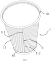
- a paper cup 1 has a hollow flared cup structure, and comprises a cup body formed by rolling a fan-shaped sheet 11 .
- the fan-shaped sheet 11 comprises a first straight edge 111, a second inclined edge 112 , an upper arc edge 113 and a lower arc edge 114 .
- the first straight edge 111 and the second inclined edge 112 are adhered to form an edge region 4 .
- the paper cup 1 further comprises a rolled rim 51 and a cup bottom 6 .
- An outer surface of the cup body is corrugated, the corrugated structure has anti-skid and anti-scalding functions, and the corrugated structure is joined at the edge region 4 of the paper cup 1 , thus enhancing a structural strength of the paper cup 1 .
- the cup body consists of a waterproof layer 8 , inner cup paper 2 , a glue layer 9 and corrugated paper 3 from inside to outside.
- a thickness of the inner cup paper 2 is greater than that of the corrugated paper 3 , so that the inner cup paper 2 is a main load-bearing structure, and the inner cup paper 2 can ensure a stiffness of the paper cup 1 and enhance a connection strength of the paper cup 1.
- the corrugated paper 3 has a corrugated structure of a transverse stripe, and a concave part of the corrugated structure of the corrugated paper 3 is adhered to the inner cup paper 2 through the glue layer 9.
- a rim rolling region 5 is arranged above the paper cup 1 , and a bending region 7 is arranged below the paper cup 1 .
- a thickness of the rim rolling region 5 is smaller than that of the cup body, and an upper part of the rim rolling region 5 is rolled to form the rolled rim 51 .
- the rolled rim 51 facilitates enhancement of strength of the cup rim, and also facilitates drinking.
- an adhering layer 62 is arranged on the cup bottom 6 , the bending region 7 is obtained by extruding the cup body, a folding layer 71 is formed by bending an end portion of the bending region 7 , and the adhering layer 62 is placed between the bending region 7 and the folding layer 71 to be adhered and fixed, so that the cup bottom 6 is fixed on a main body of the paper cup 1 .
- the adhering layer 61 is located between the bending region 7 and the folding layer 71 to support the cup bottom 6 , so that connection between the cup bottom 6 and the main body of the paper cup 1 is more stable, and a sealing performance between the cup bottom 6 and the main body of the paper cup 1 is better, thus being not easy to leak water.
- the rim rolling region 5 is obtained by extruding the cup body, an end portion of the rim rolling region 5 is rolled to form the rolled rim 51 , and the rest part of the rim rolling region is a cup wall 52 of the cup body after extrusion.
- the cup wall 52 has sufficient strength due to multi-layer composition.
- the fan-shaped sheet 11 is shown in FIG. 5 , and after the molded paper cup is torn, the unfolded cup body is the fan-shaped sheet, which is cut from a sheet shown in FIG. 11 .
- a specific process comprises: pressing a corrugation of a straight stripe on the paper 3 , wherein the straight stripe is in a direction perpendicular to a pulling direction of the paper, then arranging an edge of the single-layer corrugated paper 3 to be staggered with and parallel to an edge of the inner cup paper 2 , adhering and compounding the corrugated paper and the inner cup paper together by two composite rollers, then cutting a first end 21 of the inner cup paper to form a first straight edge 111 of the fan-shaped sheet 11 , and cutting a second inclined edge 112 , an upper arc edge 113 and a lower arc edge 114 together with the first straight edge 111 to form the fan-shaped sheet 11 shown by a solid line in FIG.
- the corrugated paper 3 has a single-layer corrugated structure without backing paper, and the corrugated paper has a corrugation of a straight stripe, wherein the straight stripe is in a direction perpendicular to the first straight edge 111 .
- the corrugation of the transverse stripe has a certain extensibility even if the corrugation has not been stretched in a transverse direction, thus meeting a structural requirement that a simplified structure is applicable to unmanned manufacturing.
- the corrugation of the corrugated paper is a transverse wavy stripe along the first straight edge to the second inclined edge, which also meets a requirement of composite extensibility, or is replaced by a discontinuous corrugated cavity transversely distributed, which comprises a circle-dot corrugated cavity or a rectangular corrugated cavity.
- the single-layer corrugated paper 3 is adhered to a fan-shaped outer peripheral surface of the inner cup paper 2 , a fan-shaped length of the inner cup paper 2 is greater than that of the corrugated paper 3 , and a first end 31 of the corrugated paper is staggered with and parallel to the first end 21 of the inner cup paper, so that the first straight edge 111 of the fan-shaped sheet 11 has an inner cup paper region which is not covered by the corrugated paper, and the region is an adhering portion 211 .
- the corrugated paper 3 among the second inclined edge 112 , the upper arc edge 113 and the lower arc edge 114 of the fan-shaped sheet is flush with the inner cup paper 2 , and then the corrugated paper and the inner cup paper are extruded at the upper arc edge 113 to form the rim rolling region 5 , and extruded at the lower arc edge 114 to form the bending region 7 .
- FIG. 6 shows a multi-layer structure of the cup body, comprising the waterproof layer 8 , the inner cup paper 2 and the corrugated paper 3 respectively, wherein the waterproof layer 8 is located on an inner side of the paper cup 1 , the waterproof layer 8 is adhesive, and adhered and fixed to the inner cup paper 2 , and the waterproof layer 8 and the inner cup paper 2 have the same shape and size, so that an inner wall of the paper cup 1 is covered with the waterproof layer 8 after the paper cup 1 is folded and molded, thus ensuring the sealing performance of the paper cup 1 .
- the fan-shaped sheet 11 is rolled and connected to form the edge region 4 shown in FIG.
- the edge region 4 comprises a four-layer reinforced structure formed by the second end 32 of the corrugated paper, the second end 22 of the inner cup paper, the first end 31 of the corrugated paper 3 and the first end 21 of the inner cup paper, and a three-layer water-tight structure formed by the second end 32 of the corrugated paper, the second end 22 of the inner cup paper and the adhering portion 211 .
- the edge region 4 after adhesion is extruded to form a multi-layer reinforced layer, thus having a supporting beam function.
- the fan-shaped sheet 11 in FIG. 6 is rolled and adhered to form the cup body, and a cross-section shape of the cup body is shown in FIG. 7 .
- the glue layer 9 is also arranged between the inner cup paper 2 and the corrugated paper 3 , the concave part of the corrugated paper 3 with the corrugated structure is adhered and fixed to the inner cup paper 2 through the glue layer 9 , and a convex part of the corrugated paper 3 with the corrugated structure forms a heat insulation cavity.
- the structure of FIG. 6 is extruded in the rim rolling region 5 to form the extruded structure of FIG. 8 .
- rim rolling region 5 When the rim rolling region 5 is extruded, folds are formed on the convex part of the corrugated paper 3 , and the folds enhance the strength of the rim rolling region 5 , thus preventing the rolled rim 51 from being deformed during use. At the moment, a part of the rim rolling region 5 enhanced by the folds is rolled to form the rolled rim 51 . The folds are rolled together into the rolled rim 51 , and the rolled rim 51 has a good structural strength.
- a principle of the solution is as follows: when the paper cup 1 is molded, the adhering portion 211 is overlapped with an inner side surface of the inner cup paper 2 first, and then the second end 22 of the inner cup paper is overlapped with the first end 31 of the corrugated paper, so that the paper cup 1 is transited evenly at a joint, thus avoiding the first end 31 of the corrugated paper from being directly connected with a main body of the inner cup paper 2 .
- an end surface of the first end 31 of the corrugated paper abuts against the waterproof layer 8
- one end of the glue layer 9 abuts against the waterproof layer 8 , thus improving a sealing performance and a connection strength of the overlapping region 4 .
- Second Embodiment is basically the same as First Embodiment, except that the edge region 4 is a connection structure. Specifically, as shown in FIG. 10 , the first end 31 of the corrugated paper is connected with the second end 32 of the corrugated paper, and a connection position is located on one side of the adhering portion 211 , or there is a gap between the first end 31 of the corrugated paper and the second end 32 of the corrugated paper.
- the edge region 4 consists of three layers formed by the second end 32 of the corrugated paper, the second end 22 of the inner cup paper and the adhering portion 211 , and two layers formed the first end 31 of the corrugated paper and the first end 21 of the inner cup paper. Compared with the edge region 4 in First Embodiment, although a number of layers is reduced, there is still sufficient strength to maintain the strength of the rim rolling region 5 , because the inner cup paper 2 is thick and has sufficient strength.
- Third Embodiment is basically the same as First Embodiment or Second Embodiment, except that the corrugated paper 3 has a plane structure, and the corrugated paper is tin paper, plastic paper, silicone paper, glass paper or asphalt paper capable of being designed in various shapes. Because the inner cup paper 2 is thick, after the edge sealing structure is rolled together with outer-layer paper to form the rolled rim, there is still sufficient strength.
Landscapes
- Engineering & Computer Science (AREA)
- Mechanical Engineering (AREA)
- Making Paper Articles (AREA)
- Packages (AREA)
- Table Devices Or Equipment (AREA)
Abstract
Description
- The present invention belongs to the technical field of paper cups, and relates to a paper cup, and particularly to a double-layer corrugated paper cup applicable to unmanned full-automatic manufacturing.
- With the enhancement of people's awareness of environmental protection, a paper cup, as a daily necessity to replace a plastic cup, has become more and more popular, and has become a daily necessity in family, restaurant and office. For example, a corrugated paper cup with heat insulation and scalding resistance is a popular paper cup product, while it is a technical problem to be solved to provide a corrugated paper cup structure capable of being applicable to an unmanned automatic production line.
- An existing corrugated cup mainly has two structures. According to a first structure, a corrugated paper sleeve is sheathed on an outer side of an inner paper cup. Since a corrugated gap cannot be kept due to extension of a single-layer corrugation, in order to keep the corrugated gap of the corrugated paper sleeve to exert an anti-scalding effect, a wavy single-layer corrugation is adhered to a layer of non-extensible backing paper first, and then the corrugated paper sleeve is made. After the corrugated paper sleeve is sheathed on an outer side of the paper cup, the backing paper of the corrugated paper sleeve is adhered and fixed to the paper cup. The corrugated paper cup with this structure can realize whole-process unmanned automatic manufacturing. The inner paper cup and the corrugated paper sleeve are automatically manufactured respectively, and then sheathed together by a sheathing machine. Due to the corrugated backing paper, the corrugated paper cup has a thick structure, wastes paper, employs a split manufacturing technology, needs many process equipment, and has a long technological process.
- According to a second structure, single-layer corrugated paper is internally arranged between inner-layer paper and outer-layer paper, and under the support of the single-layer corrugated paper, a heat insulation gap is formed between the inner-layer paper and the outer-layer paper, and a sufficient paper strength is realized. Then, the inner-layer paper, the corrugated paper and the outer-layer paper are made into a fan-shaped sheet, two edges of the fan-shaped sheet are sealed and adhered to form a sealed seam, and a cup rim is rolled. Since the corrugated paper is flexible and has a corrugated gap occupying a large space, it is difficult to achieve a sealed and water-tight state during edge sealing, so that the wavy corrugated paper will be excluded from the edge sealing structure during edge sealing, and when the cup rim is rolled, it is also difficult to roll the corrugated paper, so that the wavy corrugated paper is excluded from the rim rolling. Therefore, it is very difficult to realize unmanned automatic manufacturing of the corrugated paper cup with this structure, because the wavy corrugation is difficult to treat during edge sealing and rim rolling.
- The present invention is intended to provide a corrugated paper cup aiming at the above problems in the prior art, and the technical problem to be solved by the present invention is to provide a simplified corrugated paper cup applicable to unmanned automatic manufacturing.
- The objective of the present invention can be achieved by the following technical solution: a corrugated paper cup comprises a cup body formed by rolling a fan-shaped sheet, and the fan-shaped sheet comprises inner cup paper and single-layer corrugated paper adhered to an outer peripheral surface of the inner cup paper, wherein a first end of the corrugated paper is staggered with and parallel to a first end of the inner cup paper, so as to form a first straight edge of the fan-shaped sheet, a second end of the corrugated paper is flush with a second end of the inner cup paper, so as to form a second inclined edge of the fan-shaped sheet, a corrugated strip of the fan-shaped sheet after being unfolded is a transverse stripe in a direction from the first straight edge to the second inclined edge, when the fan-shaped sheet is rolled to form a sealed seam, the second inclined edge and the first straight edge of the fan-shaped sheet are laminated to form an edge region in which at least three layers of papers are adhered, a corrugated cavity region of the fan-shaped sheet close to an upper arc edge is flattened to form a thickness smaller than that of a middle part of the fan-shaped sheet, and a part of the extruded corrugated cavity region is rolled outwardly together with the inner cup paper to form a rolled rim.
- As an improvement, the corrugated paper between the upper arc edge and a lower arc edge of the fan-shaped sheet is flush with the inner cup paper, a corrugated cavity region of the fan-shaped sheet close to the lower arc edge is flattened to form a thickness smaller than that of the middle part of the fan-shaped sheet, and a part of the extruded corrugated cavity region is folded inwardly together with the inner cup paper to form a cup pedestal.
- In the solution, the single-layer corrugated paper is directly adhered to the inner cup paper, so that the structure of the cup body becomes simple, and a structural design that the inner cup paper and the corrugated paper are separated at the first straight edge is used, and the inner cup paper is made of a waterproof material, so that the main body can be sealed by completely depending on the adhering portion of the inner cup paper, thus preventing water leakage. On this basis, in the solution, the corrugated strip is the transverse stripe in the direction along the first straight edge to the second inclined edge, so that, on one hand, an anti- scalding effect is achieved, and on the other hand, an appearance after rolling is an upwardly spiral stripe due to the transverse stripe, and a ring-like supporting structure is formed, thus enhancing a structural strength. Moreover, a cup rim and a cup bottom are both rolled into the flattened corrugation, strengths of the cup rim and the cup bottom are enhanced, the second inclined edge and the first straight edge of the fan-shaped sheet are laminated to form the edge region in which at least three layers of papers are adhered, the edge region is extruded to form a structure equivalent to a supporting beam, and an overall strength of the paper cup is higher than that of a common double-layer paper cup.
- Secondly, with forward pulling of a roller shaft during manufacturing, paper used for manufacturing a corrugation has been stretched in a length direction of pulling progress of the paper due to influences of fine fiber arrangement and pulling and stretching, with a very small extensibility, so that the corrugation of the transverse stripe perpendicular to a pulling progress direction of the paper is pressed on the paper, which means that, the corrugated strip of the fan-shaped sheet after being unfolded is the transverse stripe in the direction along the first straight edge to the second inclined edge, the first end of the corrugated paper is parallel to and staggered with the first end of the inner cup paper, after the transverse stripe is formed by this structure and the transverse stripe is flattened and rolled into the rolled rim, not only a strength of the rolled rim can be enhanced, but also the rolled rim is avoided from being broken, because a certain degree of paper extensibility is needed during rim rolling, and the extruded corrugation of the transverse stripe meets an extensibility requirement, so that the corrugation of the transverse stripe has a certain extensibility even if the corrugation has not been stretched in a transverse direction, thus meeting a structural requirement that a simplified structure is applicable to unmanned manufacturing, and also improving the structural strength.
- In the corrugated paper cup above, after the regions of the fan-shaped sheet close to the upper arc edge and the lower arc edge are flattened, folds are formed on the flattened corrugation and rolled into the rolled rim or the cup pedestal.
- In the corrugated paper cup above, a thickness of the inner cup paper is greater than that of the corrugated paper. The corrugated paper cup has a double-layer structure with a thick interior and a thin exterior, which ensures a stiffness of the paper cup and enhances a connection strength of the paper cup.
- In the corrugated paper cup above, a corrugation of the corrugated paper is a straight stripe, and the straight stripe is in a direction perpendicular to the first straight edge.
- In the corrugated paper cup above, a corrugation of the corrugated paper is a transverse wavy stripe along the first straight edge to the second inclined edge.
- In the corrugated paper cup above, a corrugation of the corrugated paper is a discontinuous corrugated cavity transversely distributed along the first straight edge to the second inclined edge, which comprises a circle-dot corrugated cavity or a rectangular corrugated cavity.
- In the corrugated paper cup above, the first straight edge of the fan-shaped sheet has an inner cup paper region which is not covered by the corrugated paper, the region is an adhering portion, and when the second end of the inner cup paper is adhered to an outer side surface of the first end of the corrugated paper, the edge region comprises a four-layer reinforced structure formed by the second end of the corrugated paper, the second end of the inner cup paper, the first end of the corrugated paper and the first end of the inner cup paper, and a three-layer water-tight structure formed by the second end of the corrugated paper, the second end of the inner cup paper and the adhering portion. By the overlapping mode, when the rolled rim is rolled and formed, the adhering portion and the inner cup paper are rolled at the rolled rim, the adhering portion of the rolled rim is more sealed and stable, and meanwhile, an edge sealing connection strength of a rim rolling region is enhanced after the rolled rim is rolled, so that connection between two ends of the paper cup is more sealed and stable, and not easy to be separated.
- As an alternative solution, when the second end of the inner cup paper is only adhered to the adhering portion, the first end of the corrugated paper and the second end of the corrugated paper are aligned with each other or have a gap, and the edge region comprises a three-layer water-tight structure formed by the second end of the corrugated paper, the second end of the inner cup paper and the adhering portion. Although a strengthening effect is reduced, the strength can still be enhanced because the corrugation is also rolled into the rolled rim after extrusion.
- In the corrugated paper cup above, a waterproof layer is arranged on an inner wall of the inner cup paper, and when the adhering portion is overlapped on an inner side surface of the second end of the inner cup paper to form sealed adhesive connection, one end of the waterproof layer is connected with a main body of the waterproof layer. One end of the waterproof layer is connected with the main body of the waterproof layer, thus preventing water from leaking between the adhering portion and the second end of the inner cup paper, and in an overlapping region, an end surface of the first end of the corrugated paper abuts against the waterproof layer, thus further improving a sealing performance of the overlapping region.
- In the corrugated paper cup above, a glue layer is formed between the corrugated paper and the inner cup paper. In the overlapping region, one end of the glue layer abuts against the waterproof layer, thus improving the sealing performance and a connection strength of the overlapping region.
- In the corrugated paper cup above, the paper cup further comprises a cup bottom, an adhering layer is arranged on the cup bottom, the lower arc edge of the fan-shaped sheet is extruded to form a bending region, an end portion of the bending region is bent inwardly to form a folding layer, and the adhering layer is hermetically adhered between the bending region and the folding layer. The folding layer makes the adhering portion and the second end of the inner cup paper also have a connection strength.
- Compared with the prior art, the present invention has the following advantages.
- 1. The double-layer paper cup has the double-layer structure with the thick interior and the thin exterior, while separate edge sealing is performed on the inner cup paper and the corrugated paper in the edge sealing structure, which completely depends on sealed seam sealing of the inner cup paper, the edge sealing structure is realized by adhering at least three layers, and a thicker sealed seam is changed by extrusion, so that a thickness of the rim rolling region in which the edge region is located is reduced, thus being suitable for mechanical automatic rim rolling. Since the edge sealing structure of at least three layers makes the paper cup have a sufficient supporting force and keeps the strength of the paper cup, a cup wall formed in the rim rolling region will not be deformed and bent.
- 2. Since the edge sealing structure of at least three layers is cross-stacked, a better adhering effect can be achieved after edge sealing, the edge region is not easy to be torn or detached, and an anti-tear or anti-detach effect is further improved through extrusion and rim rolling.
- 3. When the corrugated paper with the corrugated structure is used, the folds are formed on a hollow part of the corrugation due to the extrusion of the corrugation, and the folds are strengthened due to creases and multi-layer overlapping, thus achieving a better strength after rim rolling.
-
-
FIG. 1 is a stereoscopic diagram of First Embodiment of the present invention; -
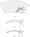
FIG. 2 is a schematic diagram of a semi-section ofFIG. 1 ; -
FIG. 3 is an enlarged view of a part B inFIG. 2 ; -
FIG. 4 is an enlarged view of a part A inFIG. 2 ; -
FIG. 5 is a schematic structural diagram of a double-layer paper cup ofFIG. 1 after being fully unfolded; -
FIG. 6 is a schematic diagram of a multi-layer composite structure of a cup body of the double-layer paper cup before edge sealing; -
FIG. 7 is a schematic structural diagram of a cross-section of a part C-C inFIG. 2 ; -
FIG. 8 is a schematic structural diagram of a cross-section of a part D-D inFIG. 2 , which is namely a schematic diagram of a specific structure of a rim rolling region of a cup rim of the double-layer paper cup after being compressed by the same thickness as the cross-section of the part C-C; -
FIG. 9 is a schematic diagram of an enlarged structure of a joint part of the double-layer paper cup; -
FIG. 10 is a schematic diagram of an enlarged structure of a joint part of a double-layer paper cup in Second Embodiment; and -
FIG. 11 is a diagram of a placement position of a fan-shaped sheet after cutting, which formsFIG. 5 after adjustment. - In the drawings: 1 refers to paper cup; 11 refers to fan-shaped sheet; 111 refers to first straight edge; 113 refers to upper arc edge; 114 refers to lower arc edge; 112 refers to second inclined edge; 2 refers to first end of inner cup paper; 211 refers to adhering portion; 22 refers to second end of inner cup paper; 3 refers to corrugated paper; 31 refers to first end of corrugated paper; 32 refers to second end of corrugated paper; 4 refers to edge region; 5 refers to rim rolling region; 51 refers to rolled rim; 52 refers to cup wall; 6 refers to cup bottom; 61 refers to cup pedestal; 62 refers to adhering layer; 7 refers to bending region; 71 refers to folding layer; 8 refers to waterproof layer; and 9 refers to glue layer.
- The following are specific embodiments of the present invention, and the technical solution of the present invention is further described with reference to the drawings, but the present invention is not limited to these embodiments.
- As shown in
FIG. 1 andFIG. 5 , apaper cup 1 has a hollow flared cup structure, and comprises a cup body formed by rolling a fan-shaped sheet 11. The fan-shapedsheet 11 comprises a firststraight edge 111, a secondinclined edge 112, anupper arc edge 113 and alower arc edge 114. The firststraight edge 111 and the secondinclined edge 112 are adhered to form anedge region 4. Thepaper cup 1 further comprises a rolledrim 51 and acup bottom 6. An outer surface of the cup body is corrugated, the corrugated structure has anti-skid and anti-scalding functions, and the corrugated structure is joined at theedge region 4 of thepaper cup 1, thus enhancing a structural strength of thepaper cup 1. - As shown in
FIG. 2 , the cup body consists of awaterproof layer 8,inner cup paper 2, aglue layer 9 andcorrugated paper 3 from inside to outside. A thickness of theinner cup paper 2 is greater than that of thecorrugated paper 3, so that theinner cup paper 2 is a main load-bearing structure, and theinner cup paper 2 can ensure a stiffness of thepaper cup 1 and enhance a connection strength of thepaper cup 1. Thecorrugated paper 3 has a corrugated structure of a transverse stripe, and a concave part of the corrugated structure of thecorrugated paper 3 is adhered to theinner cup paper 2 through theglue layer 9. Arim rolling region 5 is arranged above thepaper cup 1, and abending region 7 is arranged below thepaper cup 1. A thickness of therim rolling region 5 is smaller than that of the cup body, and an upper part of therim rolling region 5 is rolled to form the rolledrim 51. The rolledrim 51 facilitates enhancement of strength of the cup rim, and also facilitates drinking. - Specifically, as shown in
FIG. 3 , an adheringlayer 62 is arranged on thecup bottom 6, the bendingregion 7 is obtained by extruding the cup body, afolding layer 71 is formed by bending an end portion of the bendingregion 7, and the adheringlayer 62 is placed between the bendingregion 7 and thefolding layer 71 to be adhered and fixed, so that thecup bottom 6 is fixed on a main body of thepaper cup 1. The adheringlayer 61 is located between the bendingregion 7 and thefolding layer 71 to support thecup bottom 6, so that connection between thecup bottom 6 and the main body of thepaper cup 1 is more stable, and a sealing performance between thecup bottom 6 and the main body of thepaper cup 1 is better, thus being not easy to leak water. - As shown in
FIG. 4 , therim rolling region 5 is obtained by extruding the cup body, an end portion of therim rolling region 5 is rolled to form the rolledrim 51, and the rest part of the rim rolling region is acup wall 52 of the cup body after extrusion. Thecup wall 52 has sufficient strength due to multi-layer composition. - The fan-shaped
sheet 11 is shown inFIG. 5 , and after the molded paper cup is torn, the unfolded cup body is the fan-shaped sheet, which is cut from a sheet shown inFIG. 11 . A specific process comprises: pressing a corrugation of a straight stripe on thepaper 3, wherein the straight stripe is in a direction perpendicular to a pulling direction of the paper, then arranging an edge of the single-layercorrugated paper 3 to be staggered with and parallel to an edge of theinner cup paper 2, adhering and compounding the corrugated paper and the inner cup paper together by two composite rollers, then cutting afirst end 21 of the inner cup paper to form a firststraight edge 111 of the fan-shapedsheet 11, and cutting a secondinclined edge 112, anupper arc edge 113 and alower arc edge 114 together with the firststraight edge 111 to form the fan-shapedsheet 11 shown by a solid line inFIG. 11 . In this way, unmanned automatic manufacturing may be realized. Therefore, as shown inFIG. 5 andFIG. 6 , thecorrugated paper 3 has a single-layer corrugated structure without backing paper, and the corrugated paper has a corrugation of a straight stripe, wherein the straight stripe is in a direction perpendicular to the firststraight edge 111. The corrugation of the transverse stripe has a certain extensibility even if the corrugation has not been stretched in a transverse direction, thus meeting a structural requirement that a simplified structure is applicable to unmanned manufacturing. As an alternative solution, the corrugation of the corrugated paper is a transverse wavy stripe along the first straight edge to the second inclined edge, which also meets a requirement of composite extensibility, or is replaced by a discontinuous corrugated cavity transversely distributed, which comprises a circle-dot corrugated cavity or a rectangular corrugated cavity. - The single-layer
corrugated paper 3 is adhered to a fan-shaped outer peripheral surface of theinner cup paper 2, a fan-shaped length of theinner cup paper 2 is greater than that of thecorrugated paper 3, and afirst end 31 of the corrugated paper is staggered with and parallel to thefirst end 21 of the inner cup paper, so that the firststraight edge 111 of the fan-shapedsheet 11 has an inner cup paper region which is not covered by the corrugated paper, and the region is an adheringportion 211. Thecorrugated paper 3 among the secondinclined edge 112, theupper arc edge 113 and thelower arc edge 114 of the fan-shaped sheet is flush with theinner cup paper 2, and then the corrugated paper and the inner cup paper are extruded at theupper arc edge 113 to form therim rolling region 5, and extruded at thelower arc edge 114 to form the bendingregion 7. - The state of
FIG. 5 is obtained throughFIG. 6 andFIG. 9 .FIG. 6 shows a multi-layer structure of the cup body, comprising thewaterproof layer 8, theinner cup paper 2 and thecorrugated paper 3 respectively, wherein thewaterproof layer 8 is located on an inner side of thepaper cup 1, thewaterproof layer 8 is adhesive, and adhered and fixed to theinner cup paper 2, and thewaterproof layer 8 and theinner cup paper 2 have the same shape and size, so that an inner wall of thepaper cup 1 is covered with thewaterproof layer 8 after thepaper cup 1 is folded and molded, thus ensuring the sealing performance of thepaper cup 1. As shown inFIG. 9 , through the state ofFIG. 6 , the fan-shapedsheet 11 is rolled and connected to form theedge region 4 shown inFIG. 9 . Specifically, thefirst end 31 of the corrugated paper is overlapped with thesecond end 32 of the corrugated paper, and an overlapping position is staggered with the adheringportion 211. Theedge region 4 comprises a four-layer reinforced structure formed by thesecond end 32 of the corrugated paper, thesecond end 22 of the inner cup paper, thefirst end 31 of thecorrugated paper 3 and thefirst end 21 of the inner cup paper, and a three-layer water-tight structure formed by thesecond end 32 of the corrugated paper, thesecond end 22 of the inner cup paper and the adheringportion 211. Theedge region 4 after adhesion is extruded to form a multi-layer reinforced layer, thus having a supporting beam function. - The fan-shaped
sheet 11 inFIG. 6 is rolled and adhered to form the cup body, and a cross-section shape of the cup body is shown inFIG. 7 . Theglue layer 9 is also arranged between theinner cup paper 2 and thecorrugated paper 3, the concave part of thecorrugated paper 3 with the corrugated structure is adhered and fixed to theinner cup paper 2 through theglue layer 9, and a convex part of thecorrugated paper 3 with the corrugated structure forms a heat insulation cavity. The structure ofFIG. 6 is extruded in therim rolling region 5 to form the extruded structure ofFIG. 8 . When therim rolling region 5 is extruded, folds are formed on the convex part of thecorrugated paper 3, and the folds enhance the strength of therim rolling region 5, thus preventing the rolledrim 51 from being deformed during use. At the moment, a part of therim rolling region 5 enhanced by the folds is rolled to form the rolledrim 51. The folds are rolled together into the rolledrim 51, and the rolledrim 51 has a good structural strength. - A principle of the solution is as follows: when the
paper cup 1 is molded, the adheringportion 211 is overlapped with an inner side surface of theinner cup paper 2 first, and then thesecond end 22 of the inner cup paper is overlapped with thefirst end 31 of the corrugated paper, so that thepaper cup 1 is transited evenly at a joint, thus avoiding thefirst end 31 of the corrugated paper from being directly connected with a main body of theinner cup paper 2. In anoverlapping region 4, an end surface of thefirst end 31 of the corrugated paper abuts against thewaterproof layer 8, and one end of theglue layer 9 abuts against thewaterproof layer 8, thus improving a sealing performance and a connection strength of theoverlapping region 4. When the rolledrim 51 and acup pedestal 61 of thepaper cup 1 are formed, there are many layers at the overlapping portion that are not easy to be rolled, so that thepaper cup 1 is extruded to form therim rolling region 5 and the bendingregion 7, and strength weakening caused by extrusion is compensated by the folds of thecorrugated paper 3. - Second Embodiment is basically the same as First Embodiment, except that the
edge region 4 is a connection structure. Specifically, as shown inFIG. 10 , thefirst end 31 of the corrugated paper is connected with thesecond end 32 of the corrugated paper, and a connection position is located on one side of the adheringportion 211, or there is a gap between thefirst end 31 of the corrugated paper and thesecond end 32 of the corrugated paper. Theedge region 4 consists of three layers formed by thesecond end 32 of the corrugated paper, thesecond end 22 of the inner cup paper and the adheringportion 211, and two layers formed thefirst end 31 of the corrugated paper and thefirst end 21 of the inner cup paper. Compared with theedge region 4 in First Embodiment, although a number of layers is reduced, there is still sufficient strength to maintain the strength of therim rolling region 5, because theinner cup paper 2 is thick and has sufficient strength. - Third Embodiment is basically the same as First Embodiment or Second Embodiment, except that the
corrugated paper 3 has a plane structure, and the corrugated paper is tin paper, plastic paper, silicone paper, glass paper or asphalt paper capable of being designed in various shapes. Because theinner cup paper 2 is thick, after the edge sealing structure is rolled together with outer-layer paper to form the rolled rim, there is still sufficient strength. - The specific embodiments described herein are merely illustrative to the scope of the present invention. Those skilled in the technical field to which the present invention belongs may make various modifications or supplements to the specific embodiments described or make substitutions in a similar way, without departing from the scope of the present invention or exceeding the scope defined by the appended claims.
Claims (11)
- A corrugated paper cup, comprising a cup body formed by rolling a fan-shaped sheet (11), the fan-shaped sheet (11) having a first straight edge (111), a second inclined edge (112), an upper arc edge (113) and a lower arc edge (114), and the fan-shaped sheet (11) comprising inner cup paper (2) and single-layer corrugated paper (3) adhered to an outer peripheral surface of the inner cup paper (2), characterized in that,
a first end (31) of the single-layer corrugated paper (3) is staggered with and parallel to a first end (21) of the inner cup paper (2) to form the first straight edge (111) and a second end (32) of the single-layer corrugated paper (3) is flush with a second end (22) of the inner cup paper (2) to form the second inclined edge (112) of the fan-shaped sheet (11), and a corrugated strip of the fan-shaped sheet (11) unfolded is a transverse stripe in a direction from the first straight edge (111) to the second inclined edge (112), and when the fan-shaped sheet (11) is rolled to form the cup body, the second inclined edge (112) and the first straight edge (111) of the fan-shaped sheet (11) are laminated to form an seam region (4) in which at least three layers of papers are adhered, and a corrugated cavity region of the fan-shaped sheet (11) close to the upper arc edge (113) is flattened to form a first extruded corrugated cavity region and a thickness of the first extruded corrugated cavity region is smaller than that of a middle part of the fan-shaped sheet (11) and a part of the first extruded corrugated cavity region is rolled outwardly together with the inner cup paper (2) to form a rolled rim (51). - The corrugated paper cup according to claim 1, wherein the single-layer corrugated paper between the upper arc edge (113) and the lower arc edge (114) of the fan-shaped sheet (11) is flush with the inner cup paper, a corrugated cavity region of the fan-shaped sheet (11) close to the lower arc edge (114) is flattened to form a second extruded corrugated cavity region and a thickness of the second extruded corrugated cavity region is smaller than that of the middle part of the fan-shaped sheet (11) , and a part of the second extruded corrugated cavity region is folded inwardly together with the inner cup paper (2) to form a cup pedestal (61).
- The corrugated paper cup according to claim 2, wherein after the region of the fan-shaped sheet (11) close to the upper arc edge (113) or the lower arc edge (114) is flattened, folds are formed on the first or/and second flattened corrugated cavity region, and the folds are rolled into the rolled rim (51) or the cup pedestal (61).
- The corrugated paper cup according to claim 3, wherein a thickness of the inner cup paper (2) is greater than that of the single-layer corrugated paper (3).
- The corrugated paper cup according to claim 3, wherein a corrugation of the single-layer corrugated paper (3) is a straight stripe, and the straight stripe is in a direction perpendicular to the first straight edge (111).
- The corrugated paper cup according to claim 3, wherein a corrugation of the single-layer corrugated paper (3) is a transverse wavy stripe along the first straight edge (111) to the second inclined edge (112).
- The corrugated paper cup according to claim 3, wherein a corrugation of the corrugated paper (3) is a discontinuous corrugated cavity transversely distributed along the first straight edge (111) to the second inclined edge (112), which comprises a circle-dot corrugated cavity or a rectangular corrugated cavity.
- The corrugated paper cup according to claim 1, wherein the first straight edge (111) of the fan-shaped sheet (11) has an inner cup paper region which is not covered by the single-layer corrugated paper (3), the region is an adhering portion (211), and when the second end (22) of the inner cup paper is adhered to an outer side surface of the first end (31) of the corrugated paper, the edge region (4) comprises a four-layer reinforced structure formed by the second end (32) of the corrugated paper, the second end (22) of the inner cup paper, the first end (31) of the corrugated paper and the first end (21) of the inner cup paper, and a three-layer water-tight structure formed by the second end (32) of the corrugated paper, the second end (22) of the inner cup paper and the adhering portion (211).
- The corrugated paper cup according to claim 1, wherein the first straight edge (111) of the fan-shaped sheet (11) has an inner cup paper region which is not covered by the single-layer corrugated paper (3), the region is an adhering portion (211), and when the second end (22) of the inner cup paper is only adhered to the adhering portion (211), the first end (31) of the corrugated paper and the second end (32) of the corrugated paper are aligned with each other or have a gap, and the edge region (4) comprises a three-layer water-tight structure formed by the second end (32) of the corrugated paper, the second end (22) of the inner cup paper and the adhering portion (211).
- The corrugated paper cup according to claim 8 or 9, wherein a waterproof layer (8) is arranged on an inner wall of the inner cup paper (2), and when the adhering portion (211) is overlapped on an inner side surface of the second end (22) of the inner cup paper to form sealed adhesive connection, one end of the waterproof layer (8) is connected with a main body of the waterproof layer (8).
- The corrugated paper cup according to claim 10, wherein the paper cup further comprises a cup bottom (6), an adhering layer (62) is arranged on the cup bottom (6), the lower arc edge (114) of the fan-shaped sheet (11) is extruded to form a bending region (7), an end portion of the bending region (7) is bent inwardly to form a folding layer (71), and the adhering layer (62) is hermetically adhered between the bending region (7) and the folding layer (71).
Applications Claiming Priority (1)
| Application Number | Priority Date | Filing Date | Title |
|---|---|---|---|
| CN202210732384.0A CN115043061B (en) | 2022-06-27 | 2022-06-27 | A sealing structure for a double-layer paper cup |
Publications (2)
| Publication Number | Publication Date |
|---|---|
| EP4299458A2 true EP4299458A2 (en) | 2024-01-03 |
| EP4299458A3 EP4299458A3 (en) | 2024-03-13 |
Family
ID=83162782
Family Applications (1)
| Application Number | Title | Priority Date | Filing Date |
|---|---|---|---|
| EP23162551.8A Pending EP4299458A3 (en) | 2022-06-27 | 2023-03-17 | Corrugated paper cup |
Country Status (10)
| Country | Link |
|---|---|
| US (1) | US20230415948A1 (en) |
| EP (1) | EP4299458A3 (en) |
| JP (1) | JP7819981B2 (en) |
| CN (1) | CN115043061B (en) |
| AU (2) | AU2023202047A1 (en) |
| CA (1) | CA3195006A1 (en) |
| GB (1) | GB2620225B (en) |
| TW (1) | TWI857603B (en) |
| WO (1) | WO2024001988A1 (en) |
| ZA (1) | ZA202303765B (en) |
Families Citing this family (2)
| Publication number | Priority date | Publication date | Assignee | Title |
|---|---|---|---|---|
| CN115043061B (en) * | 2022-06-27 | 2026-01-30 | 湖北克拉弗特实业有限公司 | A sealing structure for a double-layer paper cup |
| CN120461938A (en) * | 2025-07-17 | 2025-08-12 | 湖北克拉弗特实业有限公司 | A method for preparing environmentally friendly paper cup coating |
Family Cites Families (17)
| Publication number | Priority date | Publication date | Assignee | Title |
|---|---|---|---|---|
| US2550520A (en) * | 1947-11-12 | 1951-04-24 | Clarence G Bennett | Joint structure for laminates |
| SE388179B (en) * | 1973-12-05 | 1976-09-27 | Ziristor Ab | STERILE PACKAGING |
| JPH09132224A (en) * | 1995-11-08 | 1997-05-20 | Toppan Printing Co Ltd | Insulation cup |
| JP2000062751A (en) * | 1998-08-17 | 2000-02-29 | Tanakaya Inc | One-stage exterior cup |
| JP2000103421A (en) * | 1998-09-28 | 2000-04-11 | Oji Paper Co Ltd | Container and manufacturing method thereof |
| US6253995B1 (en) * | 2000-05-16 | 2001-07-03 | Burrows Paper Corporation | Insulated containers and sidewalls having laterally extending flutes, and methods |
| US6926197B2 (en) * | 2002-12-12 | 2005-08-09 | Aharon Zeev Hed | Disposable and biodegradable paper cup |
| JP2004224352A (en) * | 2003-01-20 | 2004-08-12 | Oji Paper Co Ltd | Insulated paper cup |
| CN2811167Y (en) * | 2005-06-24 | 2006-08-30 | 苏笑海 | Thermal insulating paper container |
| US20070262129A1 (en) * | 2006-05-15 | 2007-11-15 | Zadravetz Robert B | Method for forming a container with corrugated wall and rolled lip |
| CN1961786A (en) * | 2006-12-01 | 2007-05-16 | 林泠镪 | Corrugated paper cup and production method thereof |
| TWM507705U (en) * | 2014-11-26 | 2015-09-01 | Pei-Ti Lin | Heat insulated leakproof container structure |
| CN204675122U (en) * | 2015-03-30 | 2015-09-30 | 林沛缇 | Insulated and leak-proof container structure |
| CN105947343A (en) * | 2016-06-21 | 2016-09-21 | 丁椒平 | Paper cup and processing technology thereof |
| CN110963178A (en) * | 2019-12-17 | 2020-04-07 | 潮州市木星纸业有限公司 | Composite paperboard, packaging paper tube and forming method thereof |
| CN218086476U (en) * | 2022-06-27 | 2022-12-20 | 湖北克拉弗特实业有限公司 | Edge sealing structure of double-layer paper cup |
| CN115043061B (en) * | 2022-06-27 | 2026-01-30 | 湖北克拉弗特实业有限公司 | A sealing structure for a double-layer paper cup |
-
2022
- 2022-06-27 CN CN202210732384.0A patent/CN115043061B/en active Active
-
2023
- 2023-03-17 EP EP23162551.8A patent/EP4299458A3/en active Pending
- 2023-03-23 ZA ZA2023/03765A patent/ZA202303765B/en unknown
- 2023-03-24 GB GB2304366.4A patent/GB2620225B/en active Active
- 2023-03-30 US US18/192,931 patent/US20230415948A1/en active Pending
- 2023-04-04 AU AU2023202047A patent/AU2023202047A1/en not_active Abandoned
- 2023-04-04 CA CA3195006A patent/CA3195006A1/en active Pending
- 2023-05-12 TW TW112117681A patent/TWI857603B/en active
- 2023-06-26 JP JP2024576679A patent/JP7819981B2/en active Active
- 2023-06-26 WO PCT/CN2023/102320 patent/WO2024001988A1/en not_active Ceased
-
2025
- 2025-02-28 AU AU2025201467A patent/AU2025201467A1/en active Pending
Also Published As
| Publication number | Publication date |
|---|---|
| EP4299458A3 (en) | 2024-03-13 |
| CN115043061A (en) | 2022-09-13 |
| AU2025201467A1 (en) | 2025-03-20 |
| WO2024001988A1 (en) | 2024-01-04 |
| GB202304366D0 (en) | 2023-05-10 |
| US20230415948A1 (en) | 2023-12-28 |
| JP7819981B2 (en) | 2026-02-25 |
| CN115043061B (en) | 2026-01-30 |
| JP2025520821A (en) | 2025-07-03 |
| TWI857603B (en) | 2024-10-01 |
| TW202413212A (en) | 2024-04-01 |
| CA3195006A1 (en) | 2023-12-27 |
| GB2620225B (en) | 2025-06-18 |
| ZA202303765B (en) | 2023-04-26 |
| AU2023202047A1 (en) | 2024-01-18 |
| GB2620225A (en) | 2024-01-03 |
Similar Documents
| Publication | Publication Date | Title |
|---|---|---|
| AU2025201467A1 (en) | Corrugated paper cup | |
| KR100679757B1 (en) | Multilayer food containers | |
| CN105947343A (en) | Paper cup and processing technology thereof | |
| CN218086476U (en) | Edge sealing structure of double-layer paper cup | |
| CA2347777A1 (en) | Insulated cup and method of manufacture | |
| US20070262129A1 (en) | Method for forming a container with corrugated wall and rolled lip | |
| CN205770597U (en) | A kind of dixie cup | |
| EP0934203A1 (en) | Multi-ply carton, blank, and formation method | |
| EP3855983A1 (en) | Drinking straw | |
| US3280709A (en) | Container and manufacture thereof | |
| EP1607336A1 (en) | Composite container liner with self-supporting sealant web | |
| JP2000095228A (en) | Heat-insulating cup | |
| CN119099977A (en) | A paper cup | |
| GB2377204A (en) | Multi-ply tissue product | |
| GB2182840A (en) | Absorbent towels | |
| CN220905840U (en) | Paper bag | |
| CN220141302U (en) | A corrugated cup | |
| JP2004332774A (en) | Flexible hose | |
| CN223765123U (en) | A foldable multi-layer paper tape | |
| CN114209500B (en) | Integrated composite diaper and its production process | |
| JP7697728B1 (en) | Aluminum laminated paper tube and its manufacturing method | |
| CN222398143U (en) | A toilet gasket | |
| CN213564797U (en) | A New High Barrier Stretch Film | |
| CN118557364A (en) | Air-sense side diaper and its manufacturing process | |
| TW202615303A (en) | Paper cup |
Legal Events
| Date | Code | Title | Description |
|---|---|---|---|
| PUAI | Public reference made under article 153(3) epc to a published international application that has entered the european phase |
Free format text: ORIGINAL CODE: 0009012 |
|
| STAA | Information on the status of an ep patent application or granted ep patent |
Free format text: STATUS: REQUEST FOR EXAMINATION WAS MADE |
|
| 17P | Request for examination filed |
Effective date: 20230327 |
|
| AK | Designated contracting states |
Kind code of ref document: A2 Designated state(s): AL AT BE BG CH CY CZ DE DK EE ES FI FR GB GR HR HU IE IS IT LI LT LU LV MC ME MK MT NL NO PL PT RO RS SE SI SK SM TR |
|
| PUAL | Search report despatched |
Free format text: ORIGINAL CODE: 0009013 |
|
| AK | Designated contracting states |
Kind code of ref document: A3 Designated state(s): AL AT BE BG CH CY CZ DE DK EE ES FI FR GB GR HR HU IE IS IT LI LT LU LV MC ME MK MT NL NO PL PT RO RS SE SI SK SM TR |
|
| RIC1 | Information provided on ipc code assigned before grant |
Ipc: B65D 3/28 20060101ALI20240206BHEP Ipc: B65D 3/22 20060101ALI20240206BHEP Ipc: B65D 3/06 20060101AFI20240206BHEP |