EP4299440A1 - Compartment for a cabin in a vehicle with retractable door angle limiter - Google Patents
Compartment for a cabin in a vehicle with retractable door angle limiter Download PDFInfo
- Publication number
- EP4299440A1 EP4299440A1 EP22181951.9A EP22181951A EP4299440A1 EP 4299440 A1 EP4299440 A1 EP 4299440A1 EP 22181951 A EP22181951 A EP 22181951A EP 4299440 A1 EP4299440 A1 EP 4299440A1
- Authority
- EP
- European Patent Office
- Prior art keywords
- compartment
- stop body
- enclosure assembly
- locking device
- cabin
- Prior art date
- Legal status (The legal status is an assumption and is not a legal conclusion. Google has not performed a legal analysis and makes no representation as to the accuracy of the status listed.)
- Granted
Links
Images


Classifications
-
- B—PERFORMING OPERATIONS; TRANSPORTING
- B64—AIRCRAFT; AVIATION; COSMONAUTICS
- B64D—EQUIPMENT FOR FITTING IN OR TO AIRCRAFT; FLIGHT SUITS; PARACHUTES; ARRANGEMENT OR MOUNTING OF POWER PLANTS OR PROPULSION TRANSMISSIONS IN AIRCRAFT
- B64D11/00—Passenger or crew accommodation; Flight-deck installations not otherwise provided for
- B64D11/04—Galleys
Definitions
- the invention relates to a compartment for a cabin in a vehicle, an installation equipment, in particular a cabin monument for a vehicle, in particular an aircraft, as well as an aircraft.
- a cabin with cabin monuments such as a galley, installed therein.
- Various cabin monuments comprise compartments for receiving items, such as standard units.
- items such as standard units.
- the exact location of a contacting point depends on the monument setup and the door frame lining adjustment, standard unit door width, exact position of the standard unit during opening process, pressurized or nonpressurized fuselage, etc.
- known solutions are limited to providing a protective material layer on the door frame lining in the form of metallic or plastic materials; and to providing large bumpers on the door frame lining or compartment walls.
- a compartment for a cabin in a vehicle comprising a compartment enclosure assembly defining an outer boundary of the compartment and comprising a receiving space, a stop body supported on or in the compartment enclosure assembly, and a locking device, wherein the receiving space is arranged to be accessible from a front of the compartment enclosure assembly, wherein the stop body is pivotally mounted on or in the compartment housing assembly about a pivot axis or slidably along an axis between a retracted position, in which the stop body does not project from the front, and an extended position, in which the stop body projects from the front to provide an end stop for a door of the compartment or for a door of an insert to be inserted into the receiving space, and wherein the locking device is adapted to selectively lock and unlock the stop body in its retracted position.
- the compartment enclosure assembly is to be understood as an arrangement of walls, frames, a framework structure that define the outer boundary of the compartment according to the invention.
- the compartment enclosure assembly may also be an integral part of a superordinate piece of installation equipment, e.g. a part of a monument, in particular a galley section inside an aircraft cabin.
- the compartment according to the invention is used for storing items in the receiving space.
- the compartment may comprise a swivable door to retain the stored items.
- a hinge may be provided, which has a hinge axis that is preferably vertical. This means, that the hinge axis extends in the z direction in an aircraft-fixed coordinate system, if it is installed in an aircraft cabin.
- the receiving space may simply be designed to hold a separate device, which comprises such a hinge and a door supported therewith.
- a separate device which comprises such a hinge and a door supported therewith.
- the receiving space may simply be designed to hold a separate device, which comprises such a hinge and a door supported therewith.
- a separate device which comprises such a hinge and a door supported therewith.
- the compartment is installed in an aircraft galley or another cabin monument, such a device may be a so-called “standard unit” that is replaceably placeable in the receiving space.
- the standard unit may comprise a door, which is supported by a vertical hinge.
- the compartment enclosure assembly may be made from aluminium, a composite material, or a combination thereof. It may comprise a box-like shape, wherein the receiving space is accessible from the front.
- the stop body is a part that is intended to be selectively moved from a retracted position into an extended position, wherein the stop body at least partially protrudes from the front of the compartment enclosure assembly in the extended position.
- a door that swivels from the front outwards to open will touch the stop body at a certain opening angle.
- the stop body is arranged in a section of the compartment enclosure assembly adjacent to the respective swivel axis.
- Adjacent installations such as cabin linings, oxygen mask containers or other components, will be protected from an impact of the door.
- the stop body may be moved by a user, for example by pulling the stop body out of the compartment enclosure assembly before opening the door. It may also be driven by a motor or a spindle upon pressing a button at the compartment to extend or retract. Furthermore, it may be moved automatically driven by gravity, as explained further below, or by a drive. It may move perpendicularly to the front along a linear course. However, it may also pivot outwards to extend and inwards to retract.
- the stop body may be an elongate element that is arranged perpendicularly to the front and that may be pulled out or pushed into the compartment enclosure assembly.
- the locking device is provided for selectively locking the stop body. As mentioned further below, and inadvertent movement of the stop body can thus be prevented to maintain a clean front.
- the locking device may be mechanically or logically coupled with other devices, such as a latching device, to improve the usability of the compartment. For example, if the stop body is moved by a user into an extended or retracted position, the locking device may be coupled with the stop body in a way that a user may press onto the stop body to lock it into the retracted state or to unlock it again.
- Other variants are conceivable, which are not coupled with the stop body, but are provided as separate devices.
- the stop body is pivotally mounted and has a center of gravity, which is distanced from the pivot axis, such that the stop body automatically pivots into the extended position by gravity when the locking device unlocks the stop body.
- the pivot axis is arranged in a distance from its center of gravity.
- the stop body may be vertically arranged in the compartment enclosure assembly and is substantially flush with or resting on the front in the retracted position. In this case, the pivot axis may be placed rearwards from the front and downwards from the center of gravity of the stop body.
- the stop body If the stop body is not locked by the locking device, it simply pivots driven by gravity in a way that the upper end of the stop body protrudes from the front and in the lower end slightly moves inwards. It is to be understood, that the compartment enclosure assembly requires a sufficient installation space for housing the stop body in its both states.
- the stop body has an elongate shape with a first end and an opposite second end, wherein the second end is arranged vertically above the first end.
- the stop body may be a bar or a rod, or any other shape with a substantially constant cross-sectional profile, such as a square, a rectangle, a T-profile, or the like along its length.
- the stop body may extend substantially vertically in the compartment enclosure assembly, wherein the center of gravity is arranged in its center.
- the pivot axis is in the lower half of the compartment enclosure assembly.
- the second end moves away from the front to protrude from the front in the extended position.
- the stop body and a plane spanned up by the front enclose an angle that is greater than zero.
- the stop body may only need to protrude a few centimeters from the front to provide a suitable end stop for the door.
- the stop body is substantially flush with or resting on the front in the retracted position. In situations, in which an interaction with the door or the receiving space is not required, the stop body substantially does not protrude from the front and thus does not create a potential obstacle in the assist space of an aircraft cabin or the like. Also, the appearance of the compartment according to the invention is harmonic when the stop body is retracted.
- the locking device comprises a wedge body, which is movably supported on or in the compartment enclosure assembly so as to be slidable parallel to the pivot axis between a first sliding position and a second sliding position, wherein the wedge body comprises a wedge surface that faces to the front, wherein a lower rear section of the stop body is coupled with a wedge surface of the wedge body, and wherein the wedge body is designed to move the stop body into the retracted position and to block the stop body in the first sliding position and to release the stop body in the second sliding position.
- the lower rear section of the stop body may be directly in contact with the wedge surface or a separate element is arranged between the stop body and the wedge surface.
- This may, for example, be a push pin, which is slidably supported in a direction perpendicular to a plane spanned up by the front.
- a push pin may be in contact with both the wedge surface and the lower rear section.
- a local thickness of the wedge body behind the stop body changes depending on the sliding position. When the wedge body is in the second sliding position, it has the smallest local thickness in a position behind the stop body, such that the rear side of the stop body can move between a forwardmost position, in which the stop body is retracted, to a rear position until it is held by the wedge surface, either directly or through separate elements.
- the stop body in the second sliding position the stop body is not prevented from pivoting.
- the wedge body in the first sliding position, the wedge body has the greatest local thickness directly behind the stop body, such that a geometrical constraint between the wedge body and the stop body, either directly or through separate elements, is provided.
- the stop body then remains in the retracted position, in which the rear side of the stop body contacts the wedge surface.
- the stop body is prevented from pivoting in the first sliding position.
- the wedge body may be coupled with an operating knob at the front of the compartment enclosure assembly, wherein the user may slide the wedge body by moving the operating knob parallel to the pivot axis in order to selectively lock or unlock the stop body.
- the locking device is arranged at a bottom wall of the compartment enclosure assembly, such that the wedge body is movable in a lateral direction along the bottom wall.
- the locking device is placed in the vicinity of latching devices or the like that are usually found in aircraft related compartments, in particular in galley applications.
- a latching device is often provided for latching doors to avoid inadvertent opening of the door during flight.
- such a latching device is arranged at a bottom wall, for example in compartments in a galley section.
- the locking device comprises a resilient element that urges the wedge body into the first sliding position.
- the stop body always reverts to the retracted state if it is not blocked, such that it does not protrude from the front when not needed. In particular during time-pressing operation of the compartment in a cramped space, this saves time and reduces the number of steps required for handling items stored in the compartment.
- the compartment enclosure assembly comprises at least one latching element, which is rotatably supported on the front to selectively move it in front of the receiving space or to move it away from the receiving space.
- a latching element is capable of latching a door in a compartment in its closed state.
- latching elements are designed as levers that are rotatably supported on one end, wherein the other end can be brought forward of the door. Hence, opening the door is prevented when the latching element is placed forward of the door.
- the locking device and the at least one latching element are arranged on the compartment enclosure assembly in such a way that the latching element is blocked in front of the receiving space when the locking device is in the first sliding position, and that the at least one latching element can be moved away from the receiving space when the locking device is in the second sliding position. Rotating the respective latching element is thus only possible when the operating knob or the like of the locking device is moved away from the first sliding position. Hence, the distance between the first sliding position and the second sliding position is sufficient to move the latching device away from the front.
- the compartment enclosure assembly comprises a recess in a lateral wall, in which the stop body is supported.
- the recess allows to place the stop body in the compartment enclosure assembly in a flush manner, such that it does not stick out the front in the retracted position.
- the receiving space is substantially hollow and designed for receiving a standard unit. Consequently, the door whose opening angle is to be limited belongs to a standard unit.
- the compartment may comprise the door and is designed for receiving other items.
- the invention further relates to an installation equipment, in particular a cabin monument and preferably a galley for a cabin of an aircraft, comprising at least one compartment according to the above.
- the installation equipment, or the cabin monument, respectively may extend from an aisle in the cabin to a nearest side wall of the cabin. However, the installation equipment may also extend over the whole width of the cabin.
- the at least one compartment is arranged in a top half of the installation equipment.
- the installation equipment in this case may be a monument that has a distinct extension in a vertical direction. For example, it may be placed on or slightly above a cabin floor and extend towards a cabin ceiling.
- the sidewall of the cabin may comprise a significant curvature, if the installation equipment is directly arranged at the sidewall. If the compartment is arranged directly adjacent to the sidewall, the stop body provides an excellent angle limitation.
- At least one lateral wall of the installation equipment is curved to complement a shape of a curved fuselage of the aircraft, in which the cabin is created.
- the installation equipment in particular a galley or another type of cabin monument, may thus be arranged flushly at a sidewall of the cabin.
- the invention relates to an aircraft comprising a cabin and having at least one installation equipment according to the above and/or at least one compartment according to the above.
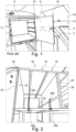
- Fig. 1 shows a part of a galley 2 in a cabin of an aircraft.
- a compartment 4 is provided in the galley 2, which is designed for receiving a standard unit 6 having a door 8, which is swivably supported on a hinge 10.
- a door lock 9 is provided on the door 8.
- the compartment 4 is arranged at a top of the galley 2 and close to a lateral wall 12 of the cabin.
- the door 8 is in an open state, in which an upper corner 14 of the door 8 contacts a box 16, which is arranged in the lateral wall 12 and is used for storing oxygen masks.
- the door 8 comprises a length of almost 30 cm and an impact on the box 16 should be avoided.
- a fixed end stop for contacting the door 8 that protrudes from the galley 2 would always reach into an assist space, which is not acceptable. Also, the exact placement of the corner 14 is hardly predictable since the standard unit 6 is a replaceable item and the exact dimensions and the swiveling path of the doors 8 of different manufacturers of standard units 6 may differ.
- Fig. 2 shows a compartment 18 in the galley 2 as an example of an installation equipment, or cabin monument, respectively, which comprises a compartment enclosure assembly 20, which comprises an upper wall 22, a bottom wall 24, a first lateral wall 26 and a second lateral wall 28.
- a recess 30 is provided, which substantially extends along the entire length of the second lateral wall 28 and houses a stop body 32, which is pivotally supported on the second lateral wall 28.
- the stop body 32 is a bar- or rod-like shaped elongate body, which may be made from a metallic material, such as aluminium, a plastic material, or a combination thereof. It may be solid or at least partially hollow.
- latching devices 36a and 36b are provided at the bottom wall 24 . These are designed in the form of levers that are rotatably supported on one of their ends. They both comprise a free end 38a and 38b that can be handled by a user to place the respective latching device 36a or 36b into an upright or a horizontal position. In the upright position, the standard unit 6 that is inserted into the compartment 18 is latched by the latching devices 36a and 36b.
- the stop body 32 is provided for creating an end stop for the door 8 of such a standard unit 6 to limit its angular motion to prevent contact with the box 16 or any other installation next to the compartment 18.
- the stop body 32 is designed for automatically pivoting into an extended position as shown in the following figures.
- the stop body 32 is shown in a lateral view. On the left-hand side in the drawing plane, the front 34 is shown.
- the stop body 32 is pivotally supported in the recess 30, wherein the pivoting axis 40 is distanced from the center of gravity 42 of the stop body 32.
- the stop body 32 furthermore comprises a first end 44, which is arranged at a bottom, and a second end 46, which is arranged at the top, i.e. vertically above the first end 44.
- the stop body 32 In the left part of fig. 3 , the stop body 32 is in a retracted position. Here, the stop body 32 is substantially flush with the front 34. Since the pivot axis 40 is further away from the front 34 than the center of gravity 42 and since the pivot axis 40 is arranged further downwards, the stop body 32 automatically pivots about the pivot axis 40 by gravity if the stop body 32 is not blocked.
- the second end 46 protrudes from the recess 30 and thus sticks out from the front 34. If the hinge axis for the door 8 is directly adjacent to the recess 30, the door 8 of the standard unit 6 may still swivel, but will contact the second end 46 of the stop body 32 when reaching an opening angle that exceeds 90°. Hence, if the stop body 32 is not blocked, it will automatically travel into the extended position and acts as an angle limiter for the door 8.
- the second end 46 may protrude from the front 34 about a distance of e.g. 5 to 25 cm and in particular 10 to 20 cm and preferably as far as possible.
- a locking device 48 is provided, which is indicated in fig. 4 and shown in further detail in figures 5a to 7c .
- the locking device 48 comprises an operating knob 50, which sticks out the bottom wall 24 over the front 34 directly adjacent to the left latching device 36a. An operator can move the operating knob 50 horizontally along the bottom wall 24. If the operating 50 is directly adjacent the left latching device 36a, the latching device 36a cannot be moved in a completely horizontal position in front of the bottom wall 24. Hence, the door 8 cannot be unlatched und thus cannot be opened. Only when the operating knob 50 is moved to the left to a position indicated with the reference numeral 52, the latching device 36a can be moved to a horizontal position. When also the right latching device 36b is horizontal, the door 8 can be opened.
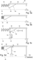
- Fig. 5a shows the locking device 48 in a schematic view.
- the operating knob 50 is on the right-hand side in the drawing plane and is connected with a rod 54, which carries a wedge body 56 having a wedge surface 58 that points to the front 34.
- a resilient element in the form of a spring 62 is provided at a side surface 60 of the wedge body 56.
- the spring 62 urges the wedge body 56 to the right-hand side of the drawing plane.
- FIG. 5b shows the operating knob 50 has moved the wedge body 56 to the left-hand side, such that the spring 62 is compressed and urges the wedge body 56 back to the right-hand side.
- the spring 62 rests on a fixed point of the compartment enclosure assembly 20, such that it is able to urge the wedge body 56 away.
- a tension spring may be provided on the other side of the wedge body 56.
- Fig. 5c schematically shows a push pin 64, which is slidably supported perpendicular to a plane spanned by the front 34, resting flushly on the wedge surface 58.
- the wedge body 56 is in its first sliding position and a local thickness of the wedge body 56 s 1 is at a maximum, such that the push pin 64 is moved outwards to the front 34.
- the push pin 64 pushes the first end 44 of the stop body 32 to the front 34.
- the wedge surface 58 travels along the rear side of the push pin 64 until the local thickness is at a minimum s 2 .
- the first end 44 of the stop body 32 is not pushed outwards to the front 34.
- the first end 44 of the stop body 32 travels inwards, i.e. away from the front 34, and the second end 46 travels outwards to protrude from the front 34.
- the spring 62 urges the wedge body 56 back into the first sliding position shown in fig. 5a and 5c and thus retracts the stop body 32 again.
- the operating knob 50 can be arranged in such a way, that when the latching device 36 a is in an open state, it holds the operating knob 50 in the second sliding position of figs. 5b and 5d .
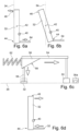
- Figs. 6a and 6b show the stop body 32 and the push pin 64 in lateral views.
- fig. 6a corresponds to fig. 5c and shows the push pin 64 holding the stop body 32 in the retracted position.
- Fig. 6b shows the push pin 64 releasing the stop body 32 and corresponds to fig. 5d .
- the transition from the second sliding position to the first sliding position is shown in fig. 6c in a top view.
- the push pin 64 pushes the stop body 32 to the front 34. This is shown in Fig. 6d in a lateral view.
- Fig. 7a shows different possible pivot axes 40 in three examples I, II and III.
- the design of the stop body 32 and the position of the pivot axis 40 can be chosen depending on the requirements, e.g. the allowed door angle.
- Fig. 7b shows a latching device 36 with two different lengths in two examples I and II.
- the length of the latching device 36 may be a dimensioning factor for the wedge body 56 if the position of the operating knob 50 in the extended position of the stop body 32 should not be far away from the free end 38 of the latching device 36 in its horizontal orientation.
- Longer latching devices 36 may allow to reduce the slope of the wedge surface 58 or to increase the pivoting motion of the stop body 32 with the same slope of the wedge surface 58. This may depend on the available installation space and/or the desired length of the latching devices 36.
- Fig. 7c shows three differently designed wedge bodies 56 in three examples I, II and III, wherein the travel distance of the push pin 64 is the same for every wedge body 56, but achieved with different sliding motions of the wedge body 56 and the knob 50.
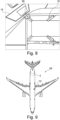
- the box 16 or other equipment or lining is close to an upper outboard edge 66 of the compartment 18.
- the stop body 32 may also function as a kind of guide rail during insertion of a standard unit 6 during catering or service.
- the upper outboard edge 66 of the standard unit 6 is hard to see during insertion and may weigh as much as 10 kg and may need to be lifted to a height of about 1,7 m.
- the stop body 32 also supports the insertion.
- fig. 9 shows an aircraft 68 having a cabin 70, in which a galley 2 having at least one of the above-described compartment 18 is installed.
Landscapes
- Engineering & Computer Science (AREA)
- Aviation & Aerospace Engineering (AREA)
- Vehicle Step Arrangements And Article Storage (AREA)
- Refrigerator Housings (AREA)
- Lock And Its Accessories (AREA)
Abstract
Description
- The invention relates to a compartment for a cabin in a vehicle, an installation equipment, in particular a cabin monument for a vehicle, in particular an aircraft, as well as an aircraft.
- Commercial and transport aircraft usually comprise a cabin with cabin monuments, such as a galley, installed therein. Various cabin monuments comprise compartments for receiving items, such as standard units. Depending on the type of cabin monument and the selected standard unit, in some installations it may happen that the door of a standard unit clashes with a part of the door frame lining when being opened. The exact location of a contacting point depends on the monument setup and the door frame lining adjustment, standard unit door width, exact position of the standard unit during opening process, pressurized or nonpressurized fuselage, etc. As prediction of the exact contacting point is almost impossible, known solutions are limited to providing a protective material layer on the door frame lining in the form of metallic or plastic materials; and to providing large bumpers on the door frame lining or compartment walls.
- It is thus an object of the invention to propose an alternative compartment with an improved protection for a door of or in the compartment or surrounding cabin lining parts, wherein a manual interaction should be as little as possible and wherein the protection should be effective without knowing the exact contact point between the door and other equipment.
- The object is met by a compartment for a cabin in a vehicle having the features of independent claim 1. Advantageous embodiments and further improvements may be gathered from the subclaims and the following description.
- A compartment for a cabin in a vehicle is proposed, comprising a compartment enclosure assembly defining an outer boundary of the compartment and comprising a receiving space, a stop body supported on or in the compartment enclosure assembly, and a locking device, wherein the receiving space is arranged to be accessible from a front of the compartment enclosure assembly, wherein the stop body is pivotally mounted on or in the compartment housing assembly about a pivot axis or slidably along an axis between a retracted position, in which the stop body does not project from the front, and an extended position, in which the stop body projects from the front to provide an end stop for a door of the compartment or for a door of an insert to be inserted into the receiving space, and wherein the locking device is adapted to selectively lock and unlock the stop body in its retracted position.
- The compartment enclosure assembly is to be understood as an arrangement of walls, frames, a framework structure that define the outer boundary of the compartment according to the invention. The compartment enclosure assembly may also be an integral part of a superordinate piece of installation equipment, e.g. a part of a monument, in particular a galley section inside an aircraft cabin. The compartment according to the invention is used for storing items in the receiving space. In particular for the use in an aircraft, the compartment may comprise a swivable door to retain the stored items. For supporting the swivable door, a hinge may be provided, which has a hinge axis that is preferably vertical. This means, that the hinge axis extends in the z direction in an aircraft-fixed coordinate system, if it is installed in an aircraft cabin.
- However, the receiving space may simply be designed to hold a separate device, which comprises such a hinge and a door supported therewith. For example, if the compartment is installed in an aircraft galley or another cabin monument, such a device may be a so-called "standard unit" that is replaceably placeable in the receiving space. The standard unit may comprise a door, which is supported by a vertical hinge.
- The compartment enclosure assembly may be made from aluminium, a composite material, or a combination thereof. It may comprise a box-like shape, wherein the receiving space is accessible from the front.
- The stop body is a part that is intended to be selectively moved from a retracted position into an extended position, wherein the stop body at least partially protrudes from the front of the compartment enclosure assembly in the extended position. When the stop body protrudes from the front of the compartment enclosure assembly, a door that swivels from the front outwards to open will touch the stop body at a certain opening angle. It is conceivable that the stop body is arranged in a section of the compartment enclosure assembly adjacent to the respective swivel axis. Thus, when the door swivels more than 90°, a part of the door will touch a part of the stop body that protrudes from the front, such that the stop body prevents the door from swiveling further. Adjacent installations, such as cabin linings, oxygen mask containers or other components, will be protected from an impact of the door.
- The stop body may be moved by a user, for example by pulling the stop body out of the compartment enclosure assembly before opening the door. It may also be driven by a motor or a spindle upon pressing a button at the compartment to extend or retract. Furthermore, it may be moved automatically driven by gravity, as explained further below, or by a drive. It may move perpendicularly to the front along a linear course. However, it may also pivot outwards to extend and inwards to retract. For example, the stop body may be an elongate element that is arranged perpendicularly to the front and that may be pulled out or pushed into the compartment enclosure assembly.
- The locking device is provided for selectively locking the stop body. As mentioned further below, and inadvertent movement of the stop body can thus be prevented to maintain a clean front. The locking device may be mechanically or logically coupled with other devices, such as a latching device, to improve the usability of the compartment. For example, if the stop body is moved by a user into an extended or retracted position, the locking device may be coupled with the stop body in a way that a user may press onto the stop body to lock it into the retracted state or to unlock it again. Other variants are conceivable, which are not coupled with the stop body, but are provided as separate devices.
- In an advantageous embodiment, the stop body is pivotally mounted and has a center of gravity, which is distanced from the pivot axis, such that the stop body automatically pivots into the extended position by gravity when the locking device unlocks the stop body. To simplify the function of the stop body, it is designed to pivot about the pivot axis automatically. For achieving this, the pivot axis is arranged in a distance from its center of gravity. For example, the stop body may be vertically arranged in the compartment enclosure assembly and is substantially flush with or resting on the front in the retracted position. In this case, the pivot axis may be placed rearwards from the front and downwards from the center of gravity of the stop body. If the stop body is not locked by the locking device, it simply pivots driven by gravity in a way that the upper end of the stop body protrudes from the front and in the lower end slightly moves inwards. It is to be understood, that the compartment enclosure assembly requires a sufficient installation space for housing the stop body in its both states.
- In an advantageous embodiment, the stop body has an elongate shape with a first end and an opposite second end, wherein the second end is arranged vertically above the first end. Thus, the stop body may be a bar or a rod, or any other shape with a substantially constant cross-sectional profile, such as a square, a rectangle, a T-profile, or the like along its length. The stop body may extend substantially vertically in the compartment enclosure assembly, wherein the center of gravity is arranged in its center. Thus, the pivot axis is in the lower half of the compartment enclosure assembly. By providing such a stop body, the required installation space for integrating the stop body is minimized.
- In an advantageous embodiment, the second end moves away from the front to protrude from the front in the extended position. Thus, in this state, the second end sticks out from the front. In the extended position, the stop body and a plane spanned up by the front enclose an angle that is greater than zero. Depending on the spatial arrangement of the door hinge and the stop body, the stop body may only need to protrude a few centimeters from the front to provide a suitable end stop for the door.
- In an advantageous embodiment, the stop body is substantially flush with or resting on the front in the retracted position. In situations, in which an interaction with the door or the receiving space is not required, the stop body substantially does not protrude from the front and thus does not create a potential obstacle in the assist space of an aircraft cabin or the like. Also, the appearance of the compartment according to the invention is harmonic when the stop body is retracted.
- In an advantageous embodiment, the locking device comprises a wedge body, which is movably supported on or in the compartment enclosure assembly so as to be slidable parallel to the pivot axis between a first sliding position and a second sliding position, wherein the wedge body comprises a wedge surface that faces to the front, wherein a lower rear section of the stop body is coupled with a wedge surface of the wedge body, and wherein the wedge body is designed to move the stop body into the retracted position and to block the stop body in the first sliding position and to release the stop body in the second sliding position. By sliding the wedge body parallel to the pivot axis, the inclined wedge surface travels along a rear side of the stop body. The lower rear section of the stop body may be directly in contact with the wedge surface or a separate element is arranged between the stop body and the wedge surface. This may, for example, be a push pin, which is slidably supported in a direction perpendicular to a plane spanned up by the front. Thus, such a push pin may be in contact with both the wedge surface and the lower rear section. A local thickness of the wedge body behind the stop body changes depending on the sliding position. When the wedge body is in the second sliding position, it has the smallest local thickness in a position behind the stop body, such that the rear side of the stop body can move between a forwardmost position, in which the stop body is retracted, to a rear position until it is held by the wedge surface, either directly or through separate elements. Hence, in the second sliding position the stop body is not prevented from pivoting. However, in the first sliding position, the wedge body has the greatest local thickness directly behind the stop body, such that a geometrical constraint between the wedge body and the stop body, either directly or through separate elements, is provided. The stop body then remains in the retracted position, in which the rear side of the stop body contacts the wedge surface. Hence, the stop body is prevented from pivoting in the first sliding position. The wedge body may be coupled with an operating knob at the front of the compartment enclosure assembly, wherein the user may slide the wedge body by moving the operating knob parallel to the pivot axis in order to selectively lock or unlock the stop body.
- In an exemplary embodiment, the locking device is arranged at a bottom wall of the compartment enclosure assembly, such that the wedge body is movable in a lateral direction along the bottom wall. Hence, the locking device is placed in the vicinity of latching devices or the like that are usually found in aircraft related compartments, in particular in galley applications. A latching device is often provided for latching doors to avoid inadvertent opening of the door during flight. Often, such a latching device is arranged at a bottom wall, for example in compartments in a galley section. Thus, there may already be a sufficient installation space in common compartments for providing the operating knob or the like that is coupled with that wedge body.
- In an advantageous embodiment, the locking device comprises a resilient element that urges the wedge body into the first sliding position. Thus, the stop body always reverts to the retracted state if it is not blocked, such that it does not protrude from the front when not needed. In particular during time-pressing operation of the compartment in a cramped space, this saves time and reduces the number of steps required for handling items stored in the compartment.
- In an advantageous embodiment, the compartment enclosure assembly comprises at least one latching element, which is rotatably supported on the front to selectively move it in front of the receiving space or to move it away from the receiving space. As mentioned before, such a latching element is capable of latching a door in a compartment in its closed state. Often, latching elements are designed as levers that are rotatably supported on one end, wherein the other end can be brought forward of the door. Hence, opening the door is prevented when the latching element is placed forward of the door.
- In an advantageous embodiment, the locking device and the at least one latching element are arranged on the compartment enclosure assembly in such a way that the latching element is blocked in front of the receiving space when the locking device is in the first sliding position, and that the at least one latching element can be moved away from the receiving space when the locking device is in the second sliding position. Rotating the respective latching element is thus only possible when the operating knob or the like of the locking device is moved away from the first sliding position. Hence, the distance between the first sliding position and the second sliding position is sufficient to move the latching device away from the front. This is also a very intuitive way of activating the stop body when unlatching the respective door, since the operating knob or the like is in the way of the latching device and just needs to be moved away to let the latching device into an open position. Unlatching will only be possible if the locking device is deactivated. Again, when the respective latching element is moved to be in front of the respective door, particularly with the resilient element mentioned above, the locking device automatically reverts into the locked state.
- In an advantageous embodiment, the compartment enclosure assembly comprises a recess in a lateral wall, in which the stop body is supported. The recess allows to place the stop body in the compartment enclosure assembly in a flush manner, such that it does not stick out the front in the retracted position.
- In an advantageous embodiment, the receiving space is substantially hollow and designed for receiving a standard unit. Consequently, the door whose opening angle is to be limited belongs to a standard unit. In an alternative, the compartment may comprise the door and is designed for receiving other items.
- The invention further relates to an installation equipment, in particular a cabin monument and preferably a galley for a cabin of an aircraft, comprising at least one compartment according to the above. The installation equipment, or the cabin monument, respectively, may extend from an aisle in the cabin to a nearest side wall of the cabin. However, the installation equipment may also extend over the whole width of the cabin.
- In an advantageous embodiment, the at least one compartment is arranged in a top half of the installation equipment. The installation equipment in this case may be a monument that has a distinct extension in a vertical direction. For example, it may be placed on or slightly above a cabin floor and extend towards a cabin ceiling. In the top half of the installation equipment, the sidewall of the cabin may comprise a significant curvature, if the installation equipment is directly arranged at the sidewall. If the compartment is arranged directly adjacent to the sidewall, the stop body provides an excellent angle limitation.
- In an advantageous embodiment, at least one lateral wall of the installation equipment is curved to complement a shape of a curved fuselage of the aircraft, in which the cabin is created. The installation equipment, in particular a galley or another type of cabin monument, may thus be arranged flushly at a sidewall of the cabin.
- Furthermore, the invention relates to an aircraft comprising a cabin and having at least one installation equipment according to the above and/or at least one compartment according to the above.
- In the following, the attached drawings are used to illustrate exemplary embodiments in more detail. The illustrations are schematic and not to scale. Identical reference numerals refer to identical or similar elements. They show:
-
Fig. 1 shows a galley according to the prior art. -
Fig. 2 shows a compartment in a front view. -
Fig. 3 shows a stop body in two lateral views. -
Fig. 4 shows the compartment with the stop body. -
Fig. 5a to 5d show a locking device in different illustrations and locking states. -
Fig. 6a to 6d show locking the stop body through the push pin in various illustrations. -
Fig. 7a to 7c show different design options for the stop body, latching elements, and wedge bodies in different illustrations. -
Fig. 8 shows an installation environment for the compartment close to a sidewall. -
Fig. 9 shows an aircraft. -
Fig. 1 shows a part of agalley 2 in a cabin of an aircraft. Here, a compartment 4 is provided in thegalley 2, which is designed for receiving astandard unit 6 having adoor 8, which is swivably supported on ahinge 10. Adoor lock 9 is provided on thedoor 8. Here, the compartment 4 is arranged at a top of thegalley 2 and close to alateral wall 12 of the cabin. In this illustration, thedoor 8 is in an open state, in which anupper corner 14 of thedoor 8 contacts abox 16, which is arranged in thelateral wall 12 and is used for storing oxygen masks. Thedoor 8 comprises a length of almost 30 cm and an impact on thebox 16 should be avoided. A fixed end stop for contacting thedoor 8 that protrudes from thegalley 2 would always reach into an assist space, which is not acceptable. Also, the exact placement of thecorner 14 is hardly predictable since thestandard unit 6 is a replaceable item and the exact dimensions and the swiveling path of thedoors 8 of different manufacturers ofstandard units 6 may differ. -
Fig. 2 shows acompartment 18 in thegalley 2 as an example of an installation equipment, or cabin monument, respectively, which comprises acompartment enclosure assembly 20, which comprises anupper wall 22, abottom wall 24, a firstlateral wall 26 and a secondlateral wall 28. At the secondlateral wall 28, arecess 30 is provided, which substantially extends along the entire length of the secondlateral wall 28 and houses astop body 32, which is pivotally supported on the secondlateral wall 28. Thestop body 32 is a bar- or rod-like shaped elongate body, which may be made from a metallic material, such as aluminium, a plastic material, or a combination thereof. It may be solid or at least partially hollow. - In
fig. 2 , it is arranged flush in afront 34 of thecompartment 18. At thebottom wall 24, twolatching devices free end respective latching device standard unit 6 that is inserted into thecompartment 18 is latched by thelatching devices - The
stop body 32 is provided for creating an end stop for thedoor 8 of such astandard unit 6 to limit its angular motion to prevent contact with thebox 16 or any other installation next to thecompartment 18. Thestop body 32 is designed for automatically pivoting into an extended position as shown in the following figures. - In
fig. 3 , thestop body 32 is shown in a lateral view. On the left-hand side in the drawing plane, the front 34 is shown. Thestop body 32 is pivotally supported in therecess 30, wherein the pivotingaxis 40 is distanced from the center ofgravity 42 of thestop body 32. Thestop body 32 furthermore comprises afirst end 44, which is arranged at a bottom, and asecond end 46, which is arranged at the top, i.e. vertically above thefirst end 44. - In the left part of
fig. 3 , thestop body 32 is in a retracted position. Here, thestop body 32 is substantially flush with the front 34. Since thepivot axis 40 is further away from the front 34 than the center ofgravity 42 and since thepivot axis 40 is arranged further downwards, thestop body 32 automatically pivots about thepivot axis 40 by gravity if thestop body 32 is not blocked. - If the
stop body 32 is in an extended position, which is shown in the right half offig. 3 , thesecond end 46 protrudes from therecess 30 and thus sticks out from the front 34. If the hinge axis for thedoor 8 is directly adjacent to therecess 30, thedoor 8 of thestandard unit 6 may still swivel, but will contact thesecond end 46 of thestop body 32 when reaching an opening angle that exceeds 90°. Hence, if thestop body 32 is not blocked, it will automatically travel into the extended position and acts as an angle limiter for thedoor 8. Thesecond end 46 may protrude from the front 34 about a distance of e.g. 5 to 25 cm and in particular 10 to 20 cm and preferably as far as possible. - It is beneficial if the
stop body 32 is blocked in situations, in which it is not required, i.e. in which thedoor 8 remains closed and latched. For this, alocking device 48 is provided, which is indicated infig. 4 and shown in further detail infigures 5a to 7c . The lockingdevice 48 comprises an operatingknob 50, which sticks out thebottom wall 24 over the front 34 directly adjacent to theleft latching device 36a. An operator can move the operatingknob 50 horizontally along thebottom wall 24. If the operating 50 is directly adjacent theleft latching device 36a, thelatching device 36a cannot be moved in a completely horizontal position in front of thebottom wall 24. Hence, thedoor 8 cannot be unlatched und thus cannot be opened. Only when the operatingknob 50 is moved to the left to a position indicated with thereference numeral 52, thelatching device 36a can be moved to a horizontal position. When also theright latching device 36b is horizontal, thedoor 8 can be opened. -
Fig. 5a shows thelocking device 48 in a schematic view. Here, the operatingknob 50 is on the right-hand side in the drawing plane and is connected with arod 54, which carries awedge body 56 having awedge surface 58 that points to the front 34. At aside surface 60 of thewedge body 56, a resilient element in the form of aspring 62 is provided. Thespring 62 urges thewedge body 56 to the right-hand side of the drawing plane. This is shown infig. 5b , where the operatingknob 50 has moved thewedge body 56 to the left-hand side, such that thespring 62 is compressed and urges thewedge body 56 back to the right-hand side. Thespring 62 rests on a fixed point of thecompartment enclosure assembly 20, such that it is able to urge thewedge body 56 away. As an alternative or in addition thereto, a tension spring may be provided on the other side of thewedge body 56. -
Fig. 5c schematically shows apush pin 64, which is slidably supported perpendicular to a plane spanned by the front 34, resting flushly on thewedge surface 58. Here, thewedge body 56 is in its first sliding position and a local thickness of the wedge body 56 s1 is at a maximum, such that thepush pin 64 is moved outwards to the front 34. Thepush pin 64 pushes thefirst end 44 of thestop body 32 to the front 34. - When moving the operating
knob 50 to the left, thewedge surface 58 travels along the rear side of thepush pin 64 until the local thickness is at a minimum s2. Hence, thefirst end 44 of thestop body 32 is not pushed outwards to the front 34. Driven by gravity, thefirst end 44 of thestop body 32 travels inwards, i.e. away from the front 34, and thesecond end 46 travels outwards to protrude from the front 34. By releasing theknob 50, thespring 62 urges thewedge body 56 back into the first sliding position shown infig. 5a and 5c and thus retracts thestop body 32 again. The operatingknob 50 can be arranged in such a way, that when the latchingdevice 36 a is in an open state, it holds the operatingknob 50 in the second sliding position offigs. 5b and 5d . -
Figs. 6a and 6b show thestop body 32 and thepush pin 64 in lateral views. Here,fig. 6a corresponds tofig. 5c and shows thepush pin 64 holding thestop body 32 in the retracted position.Fig. 6b shows thepush pin 64 releasing thestop body 32 and corresponds tofig. 5d . The transition from the second sliding position to the first sliding position is shown infig. 6c in a top view. Here, thepush pin 64 pushes thestop body 32 to the front 34. This is shown inFig. 6d in a lateral view. -
Fig. 7a shows different possible pivot axes 40 in three examples I, II and III. The lower thepivot axis 40, the higher the degree of travel of thestop body 32 and the further the extension of thesecond end 46. The design of thestop body 32 and the position of thepivot axis 40 can be chosen depending on the requirements, e.g. the allowed door angle. -
Fig. 7b shows a latchingdevice 36 with two different lengths in two examples I and II. The length of the latchingdevice 36 may be a dimensioning factor for thewedge body 56 if the position of the operatingknob 50 in the extended position of thestop body 32 should not be far away from thefree end 38 of the latchingdevice 36 in its horizontal orientation. Longer latchingdevices 36 may allow to reduce the slope of thewedge surface 58 or to increase the pivoting motion of thestop body 32 with the same slope of thewedge surface 58. This may depend on the available installation space and/or the desired length of thelatching devices 36.Fig. 7c shows three differently designedwedge bodies 56 in three examples I, II and III, wherein the travel distance of thepush pin 64 is the same for everywedge body 56, but achieved with different sliding motions of thewedge body 56 and theknob 50. - In
fig. 8 , thebox 16 or other equipment or lining is close to an upperoutboard edge 66 of thecompartment 18. Here, thestop body 32 may also function as a kind of guide rail during insertion of astandard unit 6 during catering or service. The upperoutboard edge 66 of thestandard unit 6 is hard to see during insertion and may weigh as much as 10 kg and may need to be lifted to a height of about 1,7 m. To avoid contact with other equipment, thestop body 32 also supports the insertion. - Lastly,
fig. 9 shows anaircraft 68 having acabin 70, in which agalley 2 having at least one of the above-describedcompartment 18 is installed.
Claims (15)
- Compartment (18) for a cabin in a vehicle, comprising:- a compartment enclosure assembly (20) defining an outer boundary of the compartment (18) and comprising a receiving space,- a stop body (32) supported on or in the compartment enclosure assembly (20), and- a locking device (48),wherein the receiving space is arranged to be accessible from a front (34) of the compartment enclosure assembly (20),wherein the stop body (32) is pivotally mounted on or in the compartment enclosure assembly (20) about a pivot axis (40) or slidably along an axis between a retracted position, in which the stop body (32) does not project from the front (34), and an extended position, in which the stop body (32) projects from the front (34) to provide an end stop for a door (8) of the compartment (18) or for a door (8) of an insert (6) to be inserted into the receiving space, andwherein the locking device (48) is adapted to selectively lock and unlock the stop body (32) in its retracted position.
- Compartment (18) of claim 1,
wherein the stop body (32) is pivotally mounted and has a center of gravity (42), which is distanced from the pivot axis (40), such that the stop body (32) automatically pivots into the extended position by gravity when the locking device (48) unlocks the stop body (32). - Compartment (18) of claim 2,wherein the stop body (32) has an elongate shape with a first end (44) and an opposite second end (46), andwherein the second end (46) is arranged vertically above the first end (44).
- Compartment (18) of claim 3,
wherein the second end moves away from the front (34) to protrude from the front (34) in the extended position. - Compartment (18) of any of the preceding claims,
wherein the stop body (32) is substantially flush with the front (34) in the retracted position. - Compartment (18) of any of the claims 2 to 5,wherein the locking device (48) comprises a wedge body (56), which is movably supported on or in the compartment enclosure assembly (20) so as to be slidable parallel to the pivot axis (40) between a first sliding position and a second sliding position,wherein the wedge body (56) comprises a wedge surface (58) that faces to the front (34),wherein a lower rear section of the stop body (32) is coupled with the wedge surface (58) of the wedge body, andwherein the wedge body (56) is designed to move the stop body (32) into the retracted position and to block the stop body (32) in the first sliding position and to release the stop body (32) in the second sliding position.
- Compartment (18) of claim 6,
wherein the locking device (48) is arranged at a bottom wall (24) of the compartment enclosure assembly (20), such that the wedge body (56) is movable in a lateral direction along the bottom wall (24). - Compartment (18) of claim 6 or 7,
wherein the locking device (48) comprises a resilient element (62) that urges the wedge body (56) into the first sliding position. - Compartment (18) of any of the preceding claims,
wherein the compartment enclosure assembly (20) comprises at least one latching element (36), which is rotatably supported on the front (34) to selectively move it in front (34) of the receiving space or to move it away from the receiving space. - Compartment (18) of claim 6 or 7 or 8, and 9,
wherein the locking device (48) and the at least one latching element (36) are arranged on the compartment enclosure assembly (20) in such a way that the latching element (36) is blocked in front of the receiving space when the locking device (48) is in the first sliding position, and that the at least one latching element (36) can be moved away from the receiving space when the locking device (48) is in the second sliding position. - Compartment (18) of any of the preceding claims, wherein the compartment enclosure assembly (20) comprises a recess (30) in a lateral wall (26, 28), in which the stop body (32) is supported.
- Compartment (18) of any of the preceding claims, wherein the receiving space is substantially hollow and designed for receiving a standard unit (6).
- Installation equipment, in particular a cabin monument, for a cabin of an aircraft, comprising at least one compartment (18) according to any of the preceding claims.
- Installation equipment of claim 13, wherein at least one lateral wall of the installation equipment is curved to complement a shape of a curved fuselage of the aircraft, in which the cabin is created.
- Aircraft, comprising a cabin and having at least one installation equipment according to claim 13 or 14 and/or at least one compartment (18) according to any of the claims 1 to 12.
Priority Applications (2)
| Application Number | Priority Date | Filing Date | Title |
|---|---|---|---|
| EP22181951.9A EP4299440B1 (en) | 2022-06-29 | 2022-06-29 | Compartment for a cabin in a vehicle with retractable door angle limiter |
| US18/342,894 US12304635B2 (en) | 2022-06-29 | 2023-06-28 | Compartment for a cabin in a vehicle with retractable door angle limiter |
Applications Claiming Priority (1)
| Application Number | Priority Date | Filing Date | Title |
|---|---|---|---|
| EP22181951.9A EP4299440B1 (en) | 2022-06-29 | 2022-06-29 | Compartment for a cabin in a vehicle with retractable door angle limiter |
Publications (2)
| Publication Number | Publication Date |
|---|---|
| EP4299440A1 true EP4299440A1 (en) | 2024-01-03 |
| EP4299440B1 EP4299440B1 (en) | 2025-08-06 |
Family
ID=82492635
Family Applications (1)
| Application Number | Title | Priority Date | Filing Date |
|---|---|---|---|
| EP22181951.9A Active EP4299440B1 (en) | 2022-06-29 | 2022-06-29 | Compartment for a cabin in a vehicle with retractable door angle limiter |
Country Status (2)
| Country | Link |
|---|---|
| US (1) | US12304635B2 (en) |
| EP (1) | EP4299440B1 (en) |
Families Citing this family (1)
| Publication number | Priority date | Publication date | Assignee | Title |
|---|---|---|---|---|
| US11987362B2 (en) * | 2022-07-18 | 2024-05-21 | The Boeing Company | Galley cart securing systems and methods |
Citations (2)
| Publication number | Priority date | Publication date | Assignee | Title |
|---|---|---|---|---|
| US2827863A (en) * | 1955-08-22 | 1958-03-25 | Ritzenberg Hyman | Safety device for refrigerators |
| FR2834050A1 (en) * | 2001-12-20 | 2003-06-27 | Francois Jean Henri Carre | Device to hold door of refrigerator or freezer slightly open during defrosting, uses spring in holder attached to wall to displace rod to hold door open when released |
Family Cites Families (7)
| Publication number | Priority date | Publication date | Assignee | Title |
|---|---|---|---|---|
| FR2658488A1 (en) * | 1990-02-19 | 1991-08-23 | Aerospatiale | SYSTEM FOR PROVIDING AN ENCLOSURE IN TROLLEYS OR THE LIKE. |
| US10267554B2 (en) * | 2017-08-10 | 2019-04-23 | Haier Us Appliance Solutions, Inc. | Mullion for a refrigerator appliance |
| US11242149B2 (en) * | 2019-09-12 | 2022-02-08 | B/E Aerospace, Inc. | Moveable T-divider for meal cart stowage |
| KR102284767B1 (en) * | 2019-10-18 | 2021-08-04 | 주식회사 이안이엔지 | Apparatus for keeping the opening or the closing door of cargo top vehicle |
| EP4144644B1 (en) * | 2021-09-07 | 2026-01-21 | B/E Aerospace (UK) Limited | Trolley extraction device |
| US12006042B2 (en) * | 2022-02-14 | 2024-06-11 | The Boeing Company | Aircraft galley |
| EP4299441A1 (en) * | 2022-06-29 | 2024-01-03 | B/E Aerospace, Inc. | Galley insert system |
-
2022
- 2022-06-29 EP EP22181951.9A patent/EP4299440B1/en active Active
-
2023
- 2023-06-28 US US18/342,894 patent/US12304635B2/en active Active
Patent Citations (2)
| Publication number | Priority date | Publication date | Assignee | Title |
|---|---|---|---|---|
| US2827863A (en) * | 1955-08-22 | 1958-03-25 | Ritzenberg Hyman | Safety device for refrigerators |
| FR2834050A1 (en) * | 2001-12-20 | 2003-06-27 | Francois Jean Henri Carre | Device to hold door of refrigerator or freezer slightly open during defrosting, uses spring in holder attached to wall to displace rod to hold door open when released |
Also Published As
| Publication number | Publication date |
|---|---|
| US20240002056A1 (en) | 2024-01-04 |
| US12304635B2 (en) | 2025-05-20 |
| EP4299440B1 (en) | 2025-08-06 |
Similar Documents
| Publication | Publication Date | Title |
|---|---|---|
| EP2316733B1 (en) | Aircraft galley units | |
| EP2822854B1 (en) | Aircraft cabin bin retrofit | |
| US8905497B2 (en) | Sliding arrangement | |
| US12304635B2 (en) | Compartment for a cabin in a vehicle with retractable door angle limiter | |
| CA2896340C (en) | Overhead luggage compartment for aircraft | |
| EP2801524B1 (en) | Luggage compartment and means of transport | |
| CN112478174B (en) | Movable T-divider for loading a catering trolley and aircraft galley | |
| EP1848632B1 (en) | Aircraft luggage compartment | |
| US10315767B2 (en) | Vacuum powered actuation mechanism for a vertically stowable aircraft storage unit | |
| US7744035B2 (en) | Door for compartment of the baggage-compartment type | |
| EP1132556B1 (en) | Door latch | |
| EP2995551A1 (en) | Lower deck mobile crew rest with lowered floor | |
| GB2574312A (en) | Galley monument for an aircraft | |
| US9211843B2 (en) | Assembly for storing objects in the cabin of a vehicle | |
| EP3305661B1 (en) | Vacuum powered actuation mechanism for a vertically stowable aircraft storage unit | |
| KR20140112859A (en) | storage apparatus of automobile and partition using the same | |
| JP5402227B2 (en) | Aircraft container | |
| US20120217342A1 (en) | Fastening arrangement for fastening a storage container in a compartment of an aircraft galley, storage container and aircraft galley | |
| EP4477544A1 (en) | Deployable attendant seat aircraft cabin barrier | |
| CN220363202U (en) | Vehicle with a vehicle body having a vehicle body support | |
| CN216660317U (en) | Aircraft packing box throwing device and aircraft | |
| US10647428B2 (en) | Cargo unit for an aircraft and a lower deck catering system | |
| CN116022334A (en) | Aircraft packing box throwing device and aircraft | |
| JP2007112474A (en) | Air cargo small container | |
| CA2798896A1 (en) | Galley unit and galley monument |
Legal Events
| Date | Code | Title | Description |
|---|---|---|---|
| PUAI | Public reference made under article 153(3) epc to a published international application that has entered the european phase |
Free format text: ORIGINAL CODE: 0009012 |
|
| STAA | Information on the status of an ep patent application or granted ep patent |
Free format text: STATUS: THE APPLICATION HAS BEEN PUBLISHED |
|
| AK | Designated contracting states |
Kind code of ref document: A1 Designated state(s): AL AT BE BG CH CY CZ DE DK EE ES FI FR GB GR HR HU IE IS IT LI LT LU LV MC MK MT NL NO PL PT RO RS SE SI SK SM TR |
|
| STAA | Information on the status of an ep patent application or granted ep patent |
Free format text: STATUS: REQUEST FOR EXAMINATION WAS MADE |
|
| 17P | Request for examination filed |
Effective date: 20240627 |
|
| RBV | Designated contracting states (corrected) |
Designated state(s): AL AT BE BG CH CY CZ DE DK EE ES FI FR GB GR HR HU IE IS IT LI LT LU LV MC MK MT NL NO PL PT RO RS SE SI SK SM TR |
|
| GRAP | Despatch of communication of intention to grant a patent |
Free format text: ORIGINAL CODE: EPIDOSNIGR1 |
|
| STAA | Information on the status of an ep patent application or granted ep patent |
Free format text: STATUS: GRANT OF PATENT IS INTENDED |
|
| INTG | Intention to grant announced |
Effective date: 20250317 |
|
| GRAS | Grant fee paid |
Free format text: ORIGINAL CODE: EPIDOSNIGR3 |
|
| GRAA | (expected) grant |
Free format text: ORIGINAL CODE: 0009210 |
|
| STAA | Information on the status of an ep patent application or granted ep patent |
Free format text: STATUS: THE PATENT HAS BEEN GRANTED |
|
| AK | Designated contracting states |
Kind code of ref document: B1 Designated state(s): AL AT BE BG CH CY CZ DE DK EE ES FI FR GB GR HR HU IE IS IT LI LT LU LV MC MK MT NL NO PL PT RO RS SE SI SK SM TR |
|
| REG | Reference to a national code |
Ref country code: GB Ref legal event code: FG4D |
|
| REG | Reference to a national code |
Ref country code: CH Ref legal event code: EP |
|
| REG | Reference to a national code |
Ref country code: IE Ref legal event code: FG4D |
|
| REG | Reference to a national code |
Ref country code: DE Ref legal event code: R096 Ref document number: 602022018790 Country of ref document: DE |
|
| REG | Reference to a national code |
Ref country code: NL Ref legal event code: MP Effective date: 20250806 |
|
| PG25 | Lapsed in a contracting state [announced via postgrant information from national office to epo] |
Ref country code: IS Free format text: LAPSE BECAUSE OF FAILURE TO SUBMIT A TRANSLATION OF THE DESCRIPTION OR TO PAY THE FEE WITHIN THE PRESCRIBED TIME-LIMIT Effective date: 20251206 |
|
| PG25 | Lapsed in a contracting state [announced via postgrant information from national office to epo] |
Ref country code: NO Free format text: LAPSE BECAUSE OF FAILURE TO SUBMIT A TRANSLATION OF THE DESCRIPTION OR TO PAY THE FEE WITHIN THE PRESCRIBED TIME-LIMIT Effective date: 20251106 |
|
| REG | Reference to a national code |
Ref country code: LT Ref legal event code: MG9D |
|
| PG25 | Lapsed in a contracting state [announced via postgrant information from national office to epo] |
Ref country code: PT Free format text: LAPSE BECAUSE OF FAILURE TO SUBMIT A TRANSLATION OF THE DESCRIPTION OR TO PAY THE FEE WITHIN THE PRESCRIBED TIME-LIMIT Effective date: 20251209 |
|
| PG25 | Lapsed in a contracting state [announced via postgrant information from national office to epo] |
Ref country code: FI Free format text: LAPSE BECAUSE OF FAILURE TO SUBMIT A TRANSLATION OF THE DESCRIPTION OR TO PAY THE FEE WITHIN THE PRESCRIBED TIME-LIMIT Effective date: 20250806 |
|
| PG25 | Lapsed in a contracting state [announced via postgrant information from national office to epo] |
Ref country code: HR Free format text: LAPSE BECAUSE OF FAILURE TO SUBMIT A TRANSLATION OF THE DESCRIPTION OR TO PAY THE FEE WITHIN THE PRESCRIBED TIME-LIMIT Effective date: 20250806 Ref country code: NL Free format text: LAPSE BECAUSE OF FAILURE TO SUBMIT A TRANSLATION OF THE DESCRIPTION OR TO PAY THE FEE WITHIN THE PRESCRIBED TIME-LIMIT Effective date: 20250806 |
|
| PG25 | Lapsed in a contracting state [announced via postgrant information from national office to epo] |
Ref country code: GR Free format text: LAPSE BECAUSE OF FAILURE TO SUBMIT A TRANSLATION OF THE DESCRIPTION OR TO PAY THE FEE WITHIN THE PRESCRIBED TIME-LIMIT Effective date: 20251107 |
|
| PG25 | Lapsed in a contracting state [announced via postgrant information from national office to epo] |
Ref country code: SE Free format text: LAPSE BECAUSE OF FAILURE TO SUBMIT A TRANSLATION OF THE DESCRIPTION OR TO PAY THE FEE WITHIN THE PRESCRIBED TIME-LIMIT Effective date: 20250806 |
|
| PG25 | Lapsed in a contracting state [announced via postgrant information from national office to epo] |
Ref country code: LV Free format text: LAPSE BECAUSE OF FAILURE TO SUBMIT A TRANSLATION OF THE DESCRIPTION OR TO PAY THE FEE WITHIN THE PRESCRIBED TIME-LIMIT Effective date: 20250806 |
|
| PG25 | Lapsed in a contracting state [announced via postgrant information from national office to epo] |
Ref country code: BG Free format text: LAPSE BECAUSE OF FAILURE TO SUBMIT A TRANSLATION OF THE DESCRIPTION OR TO PAY THE FEE WITHIN THE PRESCRIBED TIME-LIMIT Effective date: 20250806 Ref country code: PL Free format text: LAPSE BECAUSE OF FAILURE TO SUBMIT A TRANSLATION OF THE DESCRIPTION OR TO PAY THE FEE WITHIN THE PRESCRIBED TIME-LIMIT Effective date: 20250806 |
|
| PG25 | Lapsed in a contracting state [announced via postgrant information from national office to epo] |
Ref country code: RS Free format text: LAPSE BECAUSE OF FAILURE TO SUBMIT A TRANSLATION OF THE DESCRIPTION OR TO PAY THE FEE WITHIN THE PRESCRIBED TIME-LIMIT Effective date: 20251106 |
|
| PG25 | Lapsed in a contracting state [announced via postgrant information from national office to epo] |
Ref country code: ES Free format text: LAPSE BECAUSE OF FAILURE TO SUBMIT A TRANSLATION OF THE DESCRIPTION OR TO PAY THE FEE WITHIN THE PRESCRIBED TIME-LIMIT Effective date: 20250806 |
|
| REG | Reference to a national code |
Ref country code: AT Ref legal event code: MK05 Ref document number: 1821588 Country of ref document: AT Kind code of ref document: T Effective date: 20250806 |
|
| PG25 | Lapsed in a contracting state [announced via postgrant information from national office to epo] |
Ref country code: SM Free format text: LAPSE BECAUSE OF FAILURE TO SUBMIT A TRANSLATION OF THE DESCRIPTION OR TO PAY THE FEE WITHIN THE PRESCRIBED TIME-LIMIT Effective date: 20250806 |
|
| PG25 | Lapsed in a contracting state [announced via postgrant information from national office to epo] |
Ref country code: DK Free format text: LAPSE BECAUSE OF FAILURE TO SUBMIT A TRANSLATION OF THE DESCRIPTION OR TO PAY THE FEE WITHIN THE PRESCRIBED TIME-LIMIT Effective date: 20250806 |
|
| PG25 | Lapsed in a contracting state [announced via postgrant information from national office to epo] |
Ref country code: AT Free format text: LAPSE BECAUSE OF FAILURE TO SUBMIT A TRANSLATION OF THE DESCRIPTION OR TO PAY THE FEE WITHIN THE PRESCRIBED TIME-LIMIT Effective date: 20250806 |
|
| PG25 | Lapsed in a contracting state [announced via postgrant information from national office to epo] |
Ref country code: IT Free format text: LAPSE BECAUSE OF FAILURE TO SUBMIT A TRANSLATION OF THE DESCRIPTION OR TO PAY THE FEE WITHIN THE PRESCRIBED TIME-LIMIT Effective date: 20250806 |
|
| PG25 | Lapsed in a contracting state [announced via postgrant information from national office to epo] |
Ref country code: CZ Free format text: LAPSE BECAUSE OF FAILURE TO SUBMIT A TRANSLATION OF THE DESCRIPTION OR TO PAY THE FEE WITHIN THE PRESCRIBED TIME-LIMIT Effective date: 20250806 |
|
| PG25 | Lapsed in a contracting state [announced via postgrant information from national office to epo] |
Ref country code: EE Free format text: LAPSE BECAUSE OF FAILURE TO SUBMIT A TRANSLATION OF THE DESCRIPTION OR TO PAY THE FEE WITHIN THE PRESCRIBED TIME-LIMIT Effective date: 20250806 Ref country code: SK Free format text: LAPSE BECAUSE OF FAILURE TO SUBMIT A TRANSLATION OF THE DESCRIPTION OR TO PAY THE FEE WITHIN THE PRESCRIBED TIME-LIMIT Effective date: 20250806 |