EP4299280A1 - Vorrichtung und verfahren zum umformen von kunststoffvorformlingen zu kunststoffbehältnissen - Google Patents
Vorrichtung und verfahren zum umformen von kunststoffvorformlingen zu kunststoffbehältnissen Download PDFInfo
- Publication number
- EP4299280A1 EP4299280A1 EP23175643.8A EP23175643A EP4299280A1 EP 4299280 A1 EP4299280 A1 EP 4299280A1 EP 23175643 A EP23175643 A EP 23175643A EP 4299280 A1 EP4299280 A1 EP 4299280A1
- Authority
- EP
- European Patent Office
- Prior art keywords
- mold
- blow
- carrier
- angle
- mold carrier
- Prior art date
- Legal status (The legal status is an assumption and is not a legal conclusion. Google has not performed a legal analysis and makes no representation as to the accuracy of the status listed.)
- Granted
Links
Images
Classifications
-
- B—PERFORMING OPERATIONS; TRANSPORTING
- B29—WORKING OF PLASTICS; WORKING OF SUBSTANCES IN A PLASTIC STATE IN GENERAL
- B29C—SHAPING OR JOINING OF PLASTICS; SHAPING OF MATERIAL IN A PLASTIC STATE, NOT OTHERWISE PROVIDED FOR; AFTER-TREATMENT OF THE SHAPED PRODUCTS, e.g. REPAIRING
- B29C49/00—Blow-moulding, i.e. blowing a preform or parison to a desired shape within a mould; Apparatus therefor
- B29C49/42—Component parts, details or accessories; Auxiliary operations
- B29C49/56—Opening, closing or clamping means
-
- B—PERFORMING OPERATIONS; TRANSPORTING
- B29—WORKING OF PLASTICS; WORKING OF SUBSTANCES IN A PLASTIC STATE IN GENERAL
- B29C—SHAPING OR JOINING OF PLASTICS; SHAPING OF MATERIAL IN A PLASTIC STATE, NOT OTHERWISE PROVIDED FOR; AFTER-TREATMENT OF THE SHAPED PRODUCTS, e.g. REPAIRING
- B29C49/00—Blow-moulding, i.e. blowing a preform or parison to a desired shape within a mould; Apparatus therefor
- B29C49/28—Blow-moulding apparatus
- B29C49/28012—Blow-moulding apparatus using several moulds whereby at least one mould is different in at least one feature, e.g. size or shape
-
- B—PERFORMING OPERATIONS; TRANSPORTING
- B29—WORKING OF PLASTICS; WORKING OF SUBSTANCES IN A PLASTIC STATE IN GENERAL
- B29C—SHAPING OR JOINING OF PLASTICS; SHAPING OF MATERIAL IN A PLASTIC STATE, NOT OTHERWISE PROVIDED FOR; AFTER-TREATMENT OF THE SHAPED PRODUCTS, e.g. REPAIRING
- B29C49/00—Blow-moulding, i.e. blowing a preform or parison to a desired shape within a mould; Apparatus therefor
- B29C49/28—Blow-moulding apparatus
- B29C49/30—Blow-moulding apparatus having movable moulds or mould parts
- B29C49/36—Blow-moulding apparatus having movable moulds or mould parts rotatable about one axis
-
- B—PERFORMING OPERATIONS; TRANSPORTING
- B29—WORKING OF PLASTICS; WORKING OF SUBSTANCES IN A PLASTIC STATE IN GENERAL
- B29C—SHAPING OR JOINING OF PLASTICS; SHAPING OF MATERIAL IN A PLASTIC STATE, NOT OTHERWISE PROVIDED FOR; AFTER-TREATMENT OF THE SHAPED PRODUCTS, e.g. REPAIRING
- B29C49/00—Blow-moulding, i.e. blowing a preform or parison to a desired shape within a mould; Apparatus therefor
- B29C49/42—Component parts, details or accessories; Auxiliary operations
- B29C49/46—Component parts, details or accessories; Auxiliary operations characterised by using particular environment or blow fluids other than air
-
- B—PERFORMING OPERATIONS; TRANSPORTING
- B29—WORKING OF PLASTICS; WORKING OF SUBSTANCES IN A PLASTIC STATE IN GENERAL
- B29C—SHAPING OR JOINING OF PLASTICS; SHAPING OF MATERIAL IN A PLASTIC STATE, NOT OTHERWISE PROVIDED FOR; AFTER-TREATMENT OF THE SHAPED PRODUCTS, e.g. REPAIRING
- B29C49/00—Blow-moulding, i.e. blowing a preform or parison to a desired shape within a mould; Apparatus therefor
- B29C49/42—Component parts, details or accessories; Auxiliary operations
- B29C49/56—Opening, closing or clamping means
- B29C49/5611—Tilting movement, e.g. changing angle of the mould parts towards the vertical direction
-
- B—PERFORMING OPERATIONS; TRANSPORTING
- B29—WORKING OF PLASTICS; WORKING OF SUBSTANCES IN A PLASTIC STATE IN GENERAL
- B29C—SHAPING OR JOINING OF PLASTICS; SHAPING OF MATERIAL IN A PLASTIC STATE, NOT OTHERWISE PROVIDED FOR; AFTER-TREATMENT OF THE SHAPED PRODUCTS, e.g. REPAIRING
- B29C49/00—Blow-moulding, i.e. blowing a preform or parison to a desired shape within a mould; Apparatus therefor
- B29C49/42—Component parts, details or accessories; Auxiliary operations
- B29C49/46—Component parts, details or accessories; Auxiliary operations characterised by using particular environment or blow fluids other than air
- B29C2049/4673—Environments
- B29C2049/4697—Clean room
-
- B—PERFORMING OPERATIONS; TRANSPORTING
- B29—WORKING OF PLASTICS; WORKING OF SUBSTANCES IN A PLASTIC STATE IN GENERAL
- B29C—SHAPING OR JOINING OF PLASTICS; SHAPING OF MATERIAL IN A PLASTIC STATE, NOT OTHERWISE PROVIDED FOR; AFTER-TREATMENT OF THE SHAPED PRODUCTS, e.g. REPAIRING
- B29C49/00—Blow-moulding, i.e. blowing a preform or parison to a desired shape within a mould; Apparatus therefor
- B29C49/42—Component parts, details or accessories; Auxiliary operations
- B29C49/48—Moulds
- B29C2049/4856—Mounting, exchanging or centering moulds or parts thereof
- B29C2049/4858—Exchanging mould parts, e.g. for changing the mould size or geometry for making different products in the same mould
-
- B—PERFORMING OPERATIONS; TRANSPORTING
- B29—WORKING OF PLASTICS; WORKING OF SUBSTANCES IN A PLASTIC STATE IN GENERAL
- B29C—SHAPING OR JOINING OF PLASTICS; SHAPING OF MATERIAL IN A PLASTIC STATE, NOT OTHERWISE PROVIDED FOR; AFTER-TREATMENT OF THE SHAPED PRODUCTS, e.g. REPAIRING
- B29C49/00—Blow-moulding, i.e. blowing a preform or parison to a desired shape within a mould; Apparatus therefor
- B29C49/42—Component parts, details or accessories; Auxiliary operations
- B29C49/48—Moulds
- B29C2049/4879—Moulds characterised by mould configurations
- B29C2049/4892—Mould halves consisting of an independent main and bottom part
-
- B—PERFORMING OPERATIONS; TRANSPORTING
- B29—WORKING OF PLASTICS; WORKING OF SUBSTANCES IN A PLASTIC STATE IN GENERAL
- B29C—SHAPING OR JOINING OF PLASTICS; SHAPING OF MATERIAL IN A PLASTIC STATE, NOT OTHERWISE PROVIDED FOR; AFTER-TREATMENT OF THE SHAPED PRODUCTS, e.g. REPAIRING
- B29C49/00—Blow-moulding, i.e. blowing a preform or parison to a desired shape within a mould; Apparatus therefor
- B29C49/02—Combined blow-moulding and manufacture of the preform or the parison
- B29C49/06—Injection blow-moulding
-
- B—PERFORMING OPERATIONS; TRANSPORTING
- B29—WORKING OF PLASTICS; WORKING OF SUBSTANCES IN A PLASTIC STATE IN GENERAL
- B29C—SHAPING OR JOINING OF PLASTICS; SHAPING OF MATERIAL IN A PLASTIC STATE, NOT OTHERWISE PROVIDED FOR; AFTER-TREATMENT OF THE SHAPED PRODUCTS, e.g. REPAIRING
- B29C49/00—Blow-moulding, i.e. blowing a preform or parison to a desired shape within a mould; Apparatus therefor
- B29C49/08—Biaxial stretching during blow-moulding
- B29C49/10—Biaxial stretching during blow-moulding using mechanical means for prestretching
- B29C49/12—Stretching rods
-
- B—PERFORMING OPERATIONS; TRANSPORTING
- B29—WORKING OF PLASTICS; WORKING OF SUBSTANCES IN A PLASTIC STATE IN GENERAL
- B29C—SHAPING OR JOINING OF PLASTICS; SHAPING OF MATERIAL IN A PLASTIC STATE, NOT OTHERWISE PROVIDED FOR; AFTER-TREATMENT OF THE SHAPED PRODUCTS, e.g. REPAIRING
- B29C49/00—Blow-moulding, i.e. blowing a preform or parison to a desired shape within a mould; Apparatus therefor
- B29C49/42—Component parts, details or accessories; Auxiliary operations
- B29C49/42403—Purging or cleaning the blow-moulding apparatus
- B29C49/42405—Sterilizing
-
- B—PERFORMING OPERATIONS; TRANSPORTING
- B29—WORKING OF PLASTICS; WORKING OF SUBSTANCES IN A PLASTIC STATE IN GENERAL
- B29C—SHAPING OR JOINING OF PLASTICS; SHAPING OF MATERIAL IN A PLASTIC STATE, NOT OTHERWISE PROVIDED FOR; AFTER-TREATMENT OF THE SHAPED PRODUCTS, e.g. REPAIRING
- B29C49/00—Blow-moulding, i.e. blowing a preform or parison to a desired shape within a mould; Apparatus therefor
- B29C49/42—Component parts, details or accessories; Auxiliary operations
- B29C49/56—Opening, closing or clamping means
- B29C49/5601—Mechanically operated, i.e. closing or opening of the mould parts is done by mechanic means
- B29C49/5602—Mechanically operated, i.e. closing or opening of the mould parts is done by mechanic means using cams
-
- B—PERFORMING OPERATIONS; TRANSPORTING
- B29—WORKING OF PLASTICS; WORKING OF SUBSTANCES IN A PLASTIC STATE IN GENERAL
- B29L—INDEXING SCHEME ASSOCIATED WITH SUBCLASS B29C, RELATING TO PARTICULAR ARTICLES
- B29L2031/00—Other particular articles
- B29L2031/712—Containers; Packaging elements or accessories, Packages
- B29L2031/7158—Bottles
Definitions
- the present invention relates to a device and a method for forming plastic preforms into plastic containers.
- Such devices and methods have long been known from the prior art.
- the plastic preforms are usually formed into the plastic containers within a blow molding device by applying a flowable medium.
- the blow molding devices usually have two blow mold side parts and a base part, which together form a cavity which corresponds to a negative contour of the finished plastic container.
- devices and methods have also become known in which the plastic preforms are formed into plastic containers within a clean room. In this way, it is possible, for example, for the entire forming process to take place under sterile conditions and therefore the manufactured plastic containers do not have to be sterilized again or only with reduced effort.
- So-called blow molding machines are also known from the prior art, which also stretch the plastic preforms in their longitudinal direction during the blowing process. These are in particular so-called stretch blow molding machines.
- the blow molding devices are opened and closed.
- movements such as opening and closing the blow molding device, lifting and lifting the base part, inserting the loading device and the stretching rod into the plastic container, etc.
- several guide curves with corresponding guide rollers are provided in the applicant's internal prior art, via which these movements are controlled.
- the invention is therefore directed to a device for forming plastic preforms into plastic containers, the device having a movable support on which a plurality of blow molding devices is arranged, at least one of these blow molding devices and preferably each of these blow molding devices having at least two blow mold side parts and one in a longitudinal direction of the Plastic container has a movable base part, the blow mold side parts and the base part forming a cavity within which the plastic preforms can be formed into the plastic containers by applying a flowable medium, and the blow mold side parts are each arranged on a first mold carrier and a second mold carrier, which are movable for opening and/or closing relative to a main shaft stationary to the carrier, and the device is arranged within a clean room.
- an opening and/or closing movement of the first mold carrier takes place by a first angle and an opening and/or closing movement of the second mold carrier takes place by a second angle, the first angle and the second angle being essentially identical.
- the device according to the invention also has the advantages of cost savings and the standardization of the devices for forming plastic preforms into plastic containers through the modular principle.
- the two mold carriers therefore preferably carry out an identical movement, instead of one mold carrier being designed to be stationary. This is particularly advantageous because less space is required for the opening movement.
- the main shaft relative to which the mold carriers are movable and on which the mold carriers are mounted, is preferably arranged within the clean room.
- the main shaft preferably connects both mold carriers (mechanically) to one another.
- both mold carriers rotate at essentially the same angle with respect to a fixed bearing axis of the main shaft.
- bearing elements in the form of sealed roller bearings or plain bearings are preferably arranged, which have a significantly reduced coefficient of friction compared to metallic friction.
- the opening and closing movement of the mold carriers takes place in mirror image around a geometric axis of symmetry.
- the opening and closing movement of the mold carriers is preferably a pivoting movement and in particular a pivoting movement about a predetermined angle.
- the movement of the mold carriers is preferably controlled via at least one guide curve, which is preferably arranged within the clean room.
- the opening of the mold carrier preferably serves in particular to insert a plastic preform into the blow molding device and to be able to remove a formed plastic container from the blow molding device again after the forming.
- the mold carriers also need to be opened to replace the blow molded parts, such as the blow mold side parts and the base part.
- the mold carriers are therefore preferably opened and closed in certain or predetermined angular ranges of the movable carrier, with the respective guide curve also being arranged in this area.
- the fact that the opening and/or closing movement of the first mold carrier through a first angle and the opening and/or closing movement of the second mold carrier through a second angle are essentially identical means that it is characterized in that the opening and/or closing movement of the first mold carrier by the first angle and the opening and / or closing movement of the second mold carrier by the second angle by not more than 3 ° - 10 °, preferably by not more than 2 ° - 7 ° and particularly preferably by not more than 1 ° - 5° differ from each other.
- the opening angle between the two mold carriers is preferably between 0 and 150 degrees.
- the device for forming plastic preforms into plastic containers is preferably a blow molding machine with at least one blow molding device or blowing station.
- the flowable medium is preferably under pressure.
- the device has a blowing nozzle, which can be placed sealingly against a mouth of the plastic preforms in order to expand the plastic preforms with liquid or gaseous medium.
- the blow nozzle can seal against a support ring of the plastic preform or the blow mold.
- valve arrangement is preferably also provided, which controls the supply of blown air to the plastic preforms.
- the expansion of the container takes place using the product, so that the container is filled and expanded at the same time.
- the blow molding machine is preferably a stretch blow molding machine, which means that the preforms are stretched in the longitudinal direction by means of a stretching rod before and/or during expansion.
- the blow molding devices each have stretch rods which can be inserted into the plastic preforms and stretch the plastic preforms in their longitudinal direction.
- the stretch rods preferably have an electric drive. However, it is also conceivable to preferably control the horizontal bars over curves.
- a plurality of blow molding devices are arranged on the (common) movable support.
- This carrier is in particular a rotatable carrier.
- the blow molding devices or more precisely the mold carriers also have a locking mechanism in order to lock the mold carrier halves against one another during the blowing process.
- the blow molding devices are preferably transported within the clean room.
- the clean room is preferably bordered by several walls.
- the clean room is preferably delimited by at least one standing wall and a wall moving relative to this standing wall.
- the clean room separates the blow molds from a non-sterile environment.
- the clean room is advantageously designed in a ring or torus-like manner around the blow molding devices or forming stations and/or the transport path of the plastic containers.
- a storage device for moving the base part is arranged within the clean room.
- a storage device for the movement of the base part or for the base lifting movement runs (essentially) parallel to the longitudinal direction or longitudinal axis of the plastic container.
- the longitudinal direction is in particular a direction along a central axis of the plastic container.
- the central axis of the plastic container extends in particular (in the middle) through the opening of the container mouth and also in particular in the middle through a bottom region of the container, in particular through an injection point.
- the central axis extends in particular parallel to a vertical direction.
- a standing position of the container means that the container stands on its bottom area, which is therefore closer to the center of the earth than the mouth area of the container.
- “viewed in the longitudinal direction” is also understood to mean a position of the container in which the container is arranged upright.
- the available space within the clean room is optimally utilized. Since the storage device is located within the clean room, it preferably has a grease-free linear guide in order not to contaminate the clean room.
- the storage device for the movement of the base part or the base lifting movement is a bearing cage and in particular a ball cage.
- the ball cage preferably consists of plastic materials or a metal or has such a coating.
- a mold carrier control such as a guide curve
- the mold carrier control preferably has a disengaging element, which is preferably arranged outside the clean room.
- the shaft (main shaft) of the mold carrier control preferably penetrates the clean room, but is not fixedly connected to the mold carrier.
- the device has a mechanical coupling device which is suitable and intended to couple the base part movement and the opening and/or closing movement of the first mold carrier and/or the second mold carrier to one another.
- the coupling can preferably be implemented, for example, via a further (coupling) guide curve.
- the floor lifting movement is preferably mechanically coupled to the mold carrier opening and closing movement. This means that when the mold carrier is opened or closed, the base part is automatically raised or lowered at the same time.
- the device has a kinematic coupling device which is suitable and intended to move the first mold carrier and the to couple the second mold carrier with one another, this kinematic coupling device preferably being arranged within the clean room.
- the kinematic coupling is a movement coupling, so that a movement of one mold carrier leads to the other mold carrier also being moved.
- the device has a plurality of guide cams which are selected from a group of guide cams which includes a locking cam, a bottom lifting cam, a main guide cam, a blow nozzle cam, a guide cam for the opening and closing movement of the mold carriers and the like.
- the locking cam and/or the floor lifting cam and/or the guide cam for the opening and closing movement of the mold carriers are arranged within the clean room.
- the clean room's space is optimally utilized.
- the respective associated guide rollers of the locking cam and/or the floor lifting cam and/or the guide cam for the opening and closing movement of the mold carriers and the like are also preferably arranged within the clean room. Both the locking curve and the bottom lifting curve are arranged below the container base in relation to the longitudinal direction of the plastic container.
- the locking curve and the associated locking roller preferably serve to lock the mold carriers in the closed state during the blow molding process.
- the locking curve is formed continuously and preferably extends essentially over the entire circumferential direction below the carrier, so that the mold carriers are kept in a locked state during the entire blow molding process.
- the locking roller is preferably arranged within the clean room and preferably directly kinematically with a locking element of the locking device for locking the mold carrier is coupled. Since the locking curve and/or the floor lifting curve and/or the guide curve for the opening and closing movement of the mold carriers are located within the clean room, they are preferably also sterilized when the clean room is sterilized.
- the locking device preferably has a movable locking flap and a counterpart to this locking flap, the counterpart of the movable locking flap preferably describing the same movement sequence as the mold carrier and thus being connected in a stationary manner to the mold carrier.
- the main guide curve and/or the blow nozzle curve are arranged outside the clean room.
- the blowing nozzle curve preferably causes the blowing nozzle to advance towards the preform and correspondingly away from the preform again.
- the guide rollers and the like associated with the main guide curve and/or the blow nozzle curve are preferably located outside the clean room.
- the present invention is further directed to a method for operating a device for forming plastic preforms into plastic containers, the device having in particular a movable and in particular rotatable support (2) on which a plurality of blow molding devices (6) are arranged, at least one of which Blow molding device and preferably these blow molding devices have at least two blow mold side parts and a bottom part, which is movable in a longitudinal direction of the plastic container, the blow mold side parts and the bottom part forming a cavity within which the plastic preforms are acted upon by a flowable medium and are formed into the plastic containers, and the blow mold side parts are each arranged on a first mold carrier and a second mold carrier, which are moved relative to a main shaft stationary to the carrier for opening and / or closing, and the device is arranged within a clean room.
- the first mold carrier is opened and/or closed by a first angle and the second mold carrier by a second angle, the first angle and the second angle being essentially identical.
- the device described above is in particular set up and intended to carry out this described method, i.e. that is, all features implemented for the device described above are also disclosed for the method described here and vice versa.
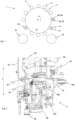
- the Figure 1 shows a schematic representation of a device 1 according to the invention for forming plastic preforms 10 into plastic containers 20.
- the plastic preforms 10 are fed to the device 1 via a feed device, such as a feed star 22, and the finished plastic containers 20 are fed to the device 1 via a discharge device, such as a discharge star 23, discharged again.
- the device 1 has a rotatable support 2 on which a plurality of blow molding devices 6 are arranged.
- Each blow molding device 6 has two blow mold side parts 6a, 6b and a first mold carrier 8a and a second mold carrier 8b, on which the side parts 6a, 6b are arranged.
- the reference number 15 indicates a clean room 15 and the reference number D indicates the direction of rotation of the device 1.
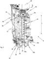
- the Figure 2 shows a schematic representation of a blow molding device 6 according to the invention.
- the blow molding device here has two blow mold side parts (not visible) and a base part 6c.
- the blow mold side parts are on the mold carriers 8a, 8b and the base part 6c on a base part carrier 8c.
- the reference number 32 indicates the locking device for locking the mold carriers 8a, 8b.
- the locking mechanism is actuated via the locking roller 35c in order to firmly close the mold carriers 8a, 8b, in particular during the blow molding process.
- a guide curve 34 is provided, which interacts with a floor lifting roller 35a and 35b and thus enables the lifting movement of the floor part 6c.
- the guide curve 34 is preferably firmly connected to one of the two mold carriers.
- the floor lift control is mounted via a bearing cage 26, in particular a ball cage.
- the roller 36 preferably cooperates with a cam (not shown) to open and/or close the mold carriers.
- the reference number 45 indicates media lines for supplying the blow molding device 6 with flowable media, such as compressed air or coolant.
- the reference symbol L indicates the longitudinal direction of the blow molding device 6 and also of the plastic containers.
- FIG 3 shows a further schematic representation of a blow molding device 6 according to the invention.
- the two blow mold side parts 6a, 6b of the blow molding device 6 can also be seen, which are arranged on the mold carriers 8a, 8b, as well as the base part 6c.
- the blow molding device 6 or more precisely the mold carriers 8a, 8b are mounted on a stationary main shaft 12, the mold carriers 8a, 8b being movable relative to the main shaft 12.
- the reference number 25 refers to the bearing device for the floor lifting movement, such as a bearing cage 26.
- the reference number 38 denotes a valve unit through which a stretching unit, not shown, is guided.
Landscapes
- Engineering & Computer Science (AREA)
- Manufacturing & Machinery (AREA)
- Mechanical Engineering (AREA)
- Blow-Moulding Or Thermoforming Of Plastics Or The Like (AREA)
Abstract
Description
- Die vorliegende Erfindung bezieht sich auf eine Vorrichtung und ein Verfahren zum Umformen von Kunststoffvorformlingen zu Kunststoffbehältnissen. Derartige Vorrichtungen und Verfahren sind aus dem Stand der Technik seit langem bekannt. Dabei werden die Kunststoffvorformlinge üblicherweise innerhalb einer Blasformeinrichtung durch Beaufschlagung mit einem fließfähigen Medium zu den Kunststoffbehältnissen umgeformt. Die Blasformeinrichtungen weisen dabei üblicherweise zwei Blasformseitenteile und ein Bodenteil auf, welche gemeinsam einen Hohlraum ausbilden, welcher einer Negativkontur des fertigen Kunststoffbehältnisses entspricht. In jüngerer Zeit sind auch Vorrichtungen und Verfahren bekannt geworden, bei denen die Umformung der Kunststoffvorformlinge zu den Kunststoffbehältnissen innerhalb eines Reinraumes erfolgt. Auf diese Weise ist es beispielsweise möglich, dass bereits der gesamte Umformungsprozess unter sterilen Bedingungen erfolgt und daher anschließend die gefertigten Kunststoffbehältnisse nicht erneut oder nur mit verringertem Aufwand sterilisiert werden müssen. Aus dem Stand der Technik sind weiterhin sog. Blasformmaschinen bekannt, welche während des Blasvorgangs die Kunststoffvorformlinge auch in ihrer Längsrichtung dehnen. Hierbei handelt es sich insbesondere um sog. Streckblasmaschinen.
- Um die Kunststoffvorformlinge in die Blasformeinrichtung einzubringen und die fertigen Kunststoffbehältnisse wieder aus den Blasformeinrichtungen zu entnehmen, werden die Blasformeinrichtungen geöffnet und geschlossen. Zur Ausführung der Bewegungen, wie das Öffnen und Schließen der Blasformeinrichtung, das An- und Abheben des Bodenteils, das Einführen der Beaufschlagungseinrichtung und der Reckstange in das Kunststoffbehältnis, etc., sind im internen Stand der Technik der Anmelderin mehrere Führungskurven mit entsprechenden Führungsrollen vorgesehen, über welche diese Bewegungen gesteuert werden.
- Aus dem internen Stand der Technik der Anmelderin ist es dabei bekannt, dass in einer bestimmten Serie bzw. Baureihe einer Vorrichtung zum Umformen von Kunststoffvorformlingen zu Kunststoffbehältnissen die Führungskurven außerhalb des Reinraums angeordnet sind, wodurch der Reinraum deutlich verkleinert wird. Gleichzeitig muss der Reinraum aber groß genug für die Öffnungsbewegung der Blasformeinrichtung sein. Diese wird durch eine bewegliche Welle realisiert, an welcher die Blasformeinrichtung bzw. deren Seitenteile und Formträger gelagert sind, so dass ein Blasformseitenteil zum Öffnen und Schließen der Blasformeinrichtung bewegbar ausgebildet ist und das andere Blasformseitenteil unbeweglich. Ein großer Teil des Innenraums des Reinraums bleibt daher ungenutzt.
- Darüber hinaus führt diese Anordnung auch zu einem deutlichen konzeptionellen Unterschied zu anderen Serien bzw. Baureihen von aus dem internen Stand der Technik der Anmelderin bekannten Vorrichtungen zum Umformen von Kunststoffvorformlingen zu Kunststoffbehältnissen und somit zu geringen Synergieeffekten und höheren Kosten.
- Der vorliegenden Erfindung liegt daher die Aufgabe zugrunde, derartige Vorrichtungen und Verfahren flexibler und kostengünstiger zu gestalten. Diese Aufgabe wird erfindungsgemäß durch die Gegenstände der unabhängigen Ansprüche erreicht. Vorteilhafte Ausführungsformen und Weiterbildungen sind Gegenstand der Unteransprüche.
- Die Erfindung ist daher auf eine Vorrichtung zum Umformen von Kunststoffvorformlingen zu Kunststoffbehältnissen gerichtet wobei die Vorrichtung einen bewegbaren Träger aufweist, an welchem eine Vielzahl von Blasformeinrichtungen angeordnet ist, wobei wenigstens eine dieser Blasformeinrichtungen und bevorzugt jede dieser Blasformeinrichtungen wenigstens zwei Blasformseitenteile und ein in einer Längsrichtung des Kunststoffbehältnisses bewegbares Bodenteil aufweist, wobei die Blasformseitenteile und das Bodenteil einen Hohlraum ausbilden, innerhalb dessen die Kunststoffvorformlinge durch Beaufschlagung mit einem fließfähigen Medium zu den Kunststoffbehältnissen umformbar sind, und die Blasformseitenteile jeweils an einem ersten Formträger und einem zweiten Formträger angeordnet sind, welche gegenüber einer zu dem Träger stationären Hauptwelle zum Öffnen und/oder Schließen bewegbar sind, und die Vorrichtung innerhalb eines Reinraums angeordnet ist.
- Erfindungsgemäß erfolgt eine Öffnungs- und/oder Schließbewegung des ersten Formträgers um einen ersten Winkel und eine Öffnungs- und/oder Schließbewegung des zweiten Formträgers um einen zweiten Winkel, wobei der erste Winkel und der zweite Winkel im Wesentlichen identisch sind.
- Es wird demnach erfindungsgemäß vorgeschlagen, anstatt einer beweglichen Welle, eine in Bezug zum Träger stationäre bzw. feststehende Welle vorzusehen und entsprechend die Öffnungsbewegung derart auszubilden, dass beide Formträger eine Öffnungs- bzw. Schließbewegung ausführen. Dabei sind, wie unten noch genauer erläutert wird, zudem auch die Führungskurven zum Teil innerhalb des Reinraums angeordnet, um die ungenutzten Räume des Reinraums besser auszunutzen.
- Die erfindungsgemäße Vorrichtung hat zudem die Vorteile einer Kosteneinsparung und der Vereinheitlichung der Vorrichtungen zum Umformen von Kunststoffvorformlingen zu Kunststoffbehältnissen durch das Baukastenprinzip.
- Bevorzugt führen demnach die beiden Formträger eine identische Bewegung aus, anstatt dass ein Formträger feststehend ausgebildet ist. Dies ist insbesondere vorteilhaft, da hierdurch weniger Platz für die Öffnungsbewegung benötigt wird. Die Hauptwelle, gegenüber der die Formträger bewegbar sind und an welcher die Formträger gelagert sind, ist bevorzugt innerhalb des Reinraums angeordnet. Die Hauptwelle verbindet dabei bevorzugt beide Formträger (mechanisch) miteinander. Vorteilhaft rotieren beide Formträger bezogen auf eine feststehende Lagerachse der Hauptwelle um den im Wesentlichen gleichen Winkel. Zwischen der Lagerachse und den Formträgern sind bevorzugt Lagerelemente in Form von abgedichteten Wälzlagern oder Gleitlagern angeordnet, die gegenüber einer metallischen Reibung einen deutlich reduzierten Reibwert aufweisen.
- Besonders bevorzugt erfolgt die Öffnungs- und Schließbewegung der Formträger spiegelbildlich um eine geometrische Symmetrieachse. Bei der Öffnungs- und Schließbewegung der Formträger handelt es sich dabei bevorzugt um eine Schwenkbewegung und insbesondere eine Schwenkbewegung um einen vorgegebenen Winkel.
- Die Bewegung der Formträger wird bevorzugt über wenigstens eine Führungskurve gesteuert, welche bevorzugt innerhalb des Reinraums angeordnet ist. Das Öffnen der Formträger dient bevorzugt insbesondere dazu, einen Kunststoffvorformling in die Blasformeinrichtung einzusetzen und nach der Umformung ein umgeformtes Kunststoffbehältnis wieder aus der Blasformeinrichtung entnehmen zu können. Auch zum Austauschen der Blasformteile, wie die Blasformseitenteile und das Bodenteil, ist ein Öffnen der Formträger erforderlich. Das Öffnen und Schließen der Formträger wird daher bevorzugt in bestimmten bzw. vorgegebenen Winkelbereichen des bewegbaren Trägers vorgenommen, wobei in diesem Bereich entsprechend auch die jeweilige Führungskurve angeordnet ist.
- Dass die Öffnungs- und/oder Schließbewegung des ersten Formträgers um einen ersten Winkel und die Öffnungs- und/oder Schließbewegung des zweiten Formträgers um einen zweiten Winkel im Wesentlichen identisch sind, bedeutet dabei, dass dadurch gekennzeichnet, dass die Öffnungs- und/oder Schließbewegung des ersten Formträgers um den ersten Winkel und die Öffnungs- und/oder Schließbewegung des zweiten Formträgers um den zweiten Winkel um nicht mehr als 3° - 10°, bevorzugt um nicht mehr als 2° - 7 ° und besonders bevorzugt um nicht mehr als 1° - 5° voneinander abweichen. Der Öffnungswinkel zwischen den beiden Formträgern liegt dabei bevorzugt zwischen 0 und 150 Grad.
- Bei der Vorrichtung zum Umformen von Kunststoffvorformlingen zu Kunststoffbehältnissen handelt es sich bevorzugt um eine Blasmaschine mit wenigstens einer Blasformeinrichtung bzw. Blasstation. Dies bedeutet, dass die Kunststoffvorformlinge zunächst in einer Heizstrecke thermisch konditioniert und anschließend durch Beaufschlagung mit einem flüssigen oder gasförmigen Medium expandiert werden. Das fließfähige Medium steht bevorzugt unter Druck. Für die Zuführung des unter Druck stehenden Mediums weist die Vorrichtung eine Blasdüse auf, welche an eine Mündung der Kunststoffvorformlinge dichtend anlegbar ist, um die Kunststoffvorformlinge so mit flüssigem oder gasförmigem Medium zu expandieren. Alternativ oder zusätzlich wäre es auch möglich dass die Blasdüse gegenüber einem Tragring des Kunststoffvorformlings oder der Blasform abdichtet.
- Daneben ist bevorzugt auch eine Ventilanordnung vorgesehen, welche die Zuführung der Blasluft an die Kunststoffvorformlinge steuert. Alternativ ist es allerdings auch denkbar, dass die Expansion des Behältnisses mittels des Produkts erfolgt, so dass eine gleichzeitige Befüllung und Expansion des Behältnisses vorgenommen wird.
- Bevorzugt handelt es sich bei der Blasmaschine um eine Streckblasmaschine, was bedeutet, dass die Vorformlinge vor und/oder während der Expansion mittels einer Reckstange in Längsrichtung gedehnt werden. Die Blasformeinrichtungen weisen dabei jeweils Reckstangen auf, welche in die Kunststoffvorformlinge einführbar sind und die Kunststoffvorformlinge in ihrer Längsrichtung dehnen. Die Reckstangen weisen dabei bevorzugt einen elektrischen Antrieb auf. Denkbar ist bevorzugt allerdings auch die Reckstangen über Kurven zu steuern.
- Bei einer vorteilhaften Ausführungsform ist eine Vielzahl von Blasformeinrichtungen an dem (gemeinsamen) beweglichen Träger angeordnet. Bei diesem Träger handelt es sich dabei insbesondere um einen drehbaren Träger. Die Blasformeinrichtungen bzw. genauer die Formträger weisen zudem einen Verriegelungsmechanismen auf, um die Formträgerhälften während des Blasvorgangs gegeneinander zu verriegeln.
- Die Blasformeinrichtungen werden bevorzugt innerhalb des Reinraums transportiert. Der Reinraum wird bevorzugt von mehreren Wandungen begrenzt. Bevorzugt wird der Reinraum dabei von wenigstens einer stehenden Wandung und einer sich gegenüber dieser stehenden Wandung bewegenden Wandung begrenzt. Der Reinraum grenzt die Blasformen insbesondere von einer unsterilen Umgebung ab. Vorteilhaft ist der Reinraum ring- oder torusartig um die Blasformeinrichtungen bzw. Umformungsstationen und/oder den Transportpfad der Kunststoffbehältnisse ausgebildet.
- Bei einer bevorzugen Ausführungsform ist eine Lagerungseinrichtung für die Bewegung des Bodenteils innerhalb des Reinraums angeordnet. Bevorzugt verläuft eine Lagerungseinrichtung für die Bewegung des Bodenteils bzw. für die Bodenhubbewegung (im Wesentlichen) parallel zu der Längsrichtung bzw. Längsachse des Kunststoffbehältnisses.
- Bei der Längsrichtung handelt es sich dabei insbesondere um eine Richtung entlang einer Mittelachse des Kunststoffbehältnisses. Die Mittelachse des Kunststoffbehältnisses erstreckt sich insbesondere (mittig) durch die Öffnung der Behältnismündung und auch insbesondere mittig durch einen Bodenbereich des Behältnisses, insbesondere durch einen Anspritzpunkt. In stehender Position des Behältnisses erstreckt sich die Mittelachse insbesondere parallel zu einer vertikalen Richtung. Eine stehende Position des Behältnisses bedeutet dabei, dass das Behältnis auf seinem Bodenbereich steht, welcher sich demnach näher am Erdmittelpunkt befindet als der Mündungsbereich des Behältnisses. Unter "in Längsrichtung betrachtet" wird daher vorliegend auch eine Position des Behältnisses verstanden, in welcher das Behältnis stehend angeordnet ist.
- Durch die Anordnung einiger Teile bzw. Einrichtungen innerhalb des Reinraums wird der vorhandene Platz innerhalb des Reinraums optimal ausgenutzt. Da sich die Lagerungseinrichtung innerhalb des Reinraums befindet weist diese bevorzugt eine fettfreie Linearführung auf, um den Reinraum nicht zu verschmutzen.
- Bei einer weiteren bevorzugten Ausführungsform handelt es sich bei der Lagerungseinrichtung für die Bewegung des Bodenteils bzw. die Bodenhubbewegung um einen Lagerkäfig und insbesondere einen Kugelkäfig. Der Kugelkäfig besteht dabei bevorzugt aus Kunststoffmaterialien oder einem Metall oder weist eine derartige Beschichtung auf.
- Zum Öffnen und Schließen der Formträger ist dabei bevorzugt eine Formträgeransteuerung, wie beispielsweise eine Führungskurve vorgesehen. Die Formträgeransteuerung (Kupplung) weist bevorzugt ein Ausrastelement auf, welches bevorzugt außerhalb des Reinraums angeordnet ist. Bevorzugt durchdringt die Welle (Hauptwelle) der Formträgeransteuerung den Reinraum, ist jedoch nicht ortsfest mit dem Formträger verbunden.
- In einer bevorzugten Ausführungsform weist die Vorrichtung eine mechanische Kopplungseinrichtung auf, welche dazu geeignet und bestimmt ist, die Bodenteilbewegung und die Öffnungs- und/oder Schließbewegung des ersten Formträgers und/oder des zweiten Formträgers miteinander zu koppeln. Die Kopplung kann dabei bevorzugt beispielsweise über eine weitere (Kopplungs)Führungskurve realisiert werden. Bevorzugt ist die Bodenhubbewegung mechanisch mit der Formträgeröffnungs- und Schließbewegung gekoppelt. Somit wird bei einem Öffnen oder Schließen der Formträger auch automatisch das Bodenteil gleichzeitig ab- oder angehoben.
- Bei einer bevorzugten Ausführungsform weist die Vorrichtung eine kinematische Kopplungseinrichtung auf, welche dazu geeignet und bestimmt ist, um den ersten Formträger und den zweiten Formträger miteinander zu koppeln, wobei diese kinematische Kopplungseinrichtung bevorzugt innerhalb des Reinraums angeordnet ist.
- Bei der kinematischen Kopplung handelt es sich dabei um eine Bewegungskopplung, so dass demnach eine Bewegung des einen Formträgers dazu führt, dass auch der andere Formträger bewegt wird.
- Bei einer weiteren bevorzugten Ausführungsform weist die Vorrichtung eine Vielzahl von Führungskurven auf, welche aus einer Gruppe von Führungskurven ausgewählt sind, welche eine Verriegelungskurve, eine Bodenhubkurve, eine Hauptführungskurve, eine Blasdüsenkurve, eine Führungskurve für die Öffnungs- und Schließbewegung der Formträger und dergleichen enthält.
- Besonders bevorzugt sind dabei die Verriegelungskurve und/oder die Bodenhubkurve und/oder die Führungskurve für die Öffnungs- und Schließbewegung der Formträger innerhalb des Reinraums angeordnet. Durch die zusätzliche Anordnung bestimmter Führungskurven innerhalb des Reinraums, anstatt außerhalb, erfolgt eine optimale Platzausnutzung des Reinraums.
- Bevorzugt sind auch die jeweiligen zugehörige Führungsrollen der Verriegelungskurve und/oder der Bodenhubkurve und/oder der Führungskurve für die Öffnungs- und Schließbewegung der Formträger und dergleichen innerhalb des Reinraums angeordnet. Sowohl die Verriegelungskurve als auch die Bodenhubkurve sind dabei bezogen auf die Längsrichtung des Kunststoffbehältnisses unterhalb des Behälterbodens angeordnet.
- Die Verriegelungskurve und die zugehörige Verriegelungsrolle dienen dabei bevorzugt dazu die Formträger im geschlossenen Zustand während des Blasformvorgangs zu verriegeln. Die Verriegelungskurve ist dabei durchgehend ausgebildet und erstreckt sich bevorzugt im Wesentlichen über die gesamte Umfangsrichtung unterhalb des Trägers, so dass die Formträger während des gesamten Blasformprozesses in einem verriegelten Zustand gehalten werden.
- Die Verriegelungsrolle ist bevorzugt innerhalb des Reinraums angeordnet und bevorzugt direkt kinematisch mit einem Verriegelungselement der Verriegelungseinrichtung zum Verriegeln der Formträger gekoppelt. Da sich die Verriegelungskurve und/oder die Bodenhubkurve und/oder die Führungskurve für die Öffnungs- und Schließbewegung der Formträger innerhalb des Reinraums befinden werden diese bevorzugt mitsterilisiert, wenn der Reinraum sterilisiert wird.
- Die Verriegelungseinrichtung weist bevorzugt eine bewegliche Verriegelungsklappe und ein Gegenstück zu dieser Verriegelungsklappe auf, wobei das Gegenstück der beweglichen Verriegelungsklappe bevorzugt den gleichen Bewegungsablauf wie der Formträger beschreibt und somit ortsfest mit dem Formträger verbunden ist.
- Bei einer weiteren bevorzugten Ausführungsform sind die Hauptführungskurve und/oder die Blasdüsenkurve außerhalb des Reinraums angeordnet. Die Blasdüsenkurve bewirkt dabei bevorzugt die Zustellung der Blasdüse auf den Vorformling zu und entsprechend auch wieder von dem Vorformling weg.
- Bevorzugt befindet sich dabei die zu der Hauptführungskurve und/oder der Blasdüsenkurve zugehörige Führungsrollen und dergleichen außerhalb des Reinraums.
- Die vorliegende Erfindung ist weiter auf ein Verfahren zum Betreiben einer Vorrichtung zum Umformen von Kunststoffvorformlingen zu Kunststoffbehältnissen gerichtet, wobei die Vorrichtung insbesondere einen bewegbaren und insbesondere drehbaren Träger (2) aufweist, an welchem eine Vielzahl von Blasformeinrichtungen (6) angeordnet ist wobei wenigstens eine dieser Blasformeinrichtung und bevorzugt diese Blasformeinrichtungen wenigstens zwei Blasformseitenteile und ein Bodenteil, welches in einer Längsrichtung des Kunststoffbehältnisses bewegbar ist, aufweisen wobei die Blasformseitenteile und das Bodenteil einen Hohlraum ausbilden, innerhalb dessen die Kunststoffvorformlinge mit einem fließfähigen Medium beaufschlagt werden und zu den Kunststoffbehältnissen umgeformt werden, und die Blasformseitenteile jeweils an einem ersten Formträger und einem zweiten Formträger angeordnet sind, welche gegenüber einer zu dem Träger stationären Hauptwelle zum Öffnen und/oder Schließen bewegt werden, und die Vorrichtung innerhalb eines Reinraums angeordnet ist.
- Erfindungsgemäß wird der erste Formträger um einen ersten Winkel geöffnet und/oder geschlossen wird und der zweite Formträger um einen zweiten Winkel, wobei der erste Winkel und der zweite Winkel im Wesentlichen identisch sind.
- Dabei ist die oben beschriebene Vorrichtung insbesondere dazu eingerichtet und dafür vorgesehen, dieses beschriebene Verfahren durchzuführen, d. h., dass alle für die obig beschriebene Vorrichtung ausgeführten Merkmale ebenso für das hier beschriebene Verfahren offenbart sind und umgekehrt.
- Weitere Vorteile und Ausführungsformen ergeben sich aus den beigefügten Zeichnungen. Darin zeigt:
- Fig. 1
- eine schematische Darstellung einer erfindungsgemäßen Vorrichtung;
- Fig. 2
- eine schematische Darstellung einer erfindungsgemäßen Blasformeinrichtung; und
- Fig. 3
- eine weitere schematische Darstellung einer erfindungsgemäßen Blasformeinrichtung.
- Die
Figur 1 zeigt eine schematische Darstellung einer erfindungsgemäßen Vorrichtung 1 zum Umformen von Kunststoffvorformlingen 10 zu Kunststoffbehältnissen 20. Dabei werden die Kunststoffvorformlinge 10 über eine Zuführeinrichtung, wie etwa einem Zuführstern 22, der Vorrichtung 1 zugeführt und die fertigen Kunststoffbehältnisse 20 werden der Vorrichtung 1 über eine Abführeinrichtung, wie einen Abführstern 23, wieder abgeführt. Die Vorrichtung 1 weist einen drehbaren Träger 2 auf, an dem eine Vielzahl von Blasformeinrichtungen 6 angeordnet ist. Jede Blasformeinrichtung 6 weist dabei zwei Blasformseitenteile 6a, 6b und einen ersten Formträger 8a und einen zweiten Formträger 8b auf, an welchen die Seitenteile 6a, 6b angeordnet sind. Das Bezugszeichen 15 kennzeichnet einen Reinraum 15 und das Bezugszeichen D die Drehrichtung der Vorrichtung 1. - Die
Figur 2 zeigt eine schematische Darstellung einer erfindungsgemäßen Blasformeinrichtung 6. Die Blasformeinrichtung weist hier zwei Blasformseitenteile (nicht erkennbar) auf sowie ein Bodenteil 6c. Die Blasformseitenteile sind dabei an den Formträgern 8a, 8b und das Bodenteil 6c an einem Bodenteilträger 8c. - Das Bezugszeichen 32 kennzeichnet die Verriegelungseinrichtung zum Verriegeln der Formträger 8a, 8b. Die Verriegelungseinreichung wird dabei über die Verrieglungsrolle 35c betätigt um die Formträger 8a, 8b, insbesondere während des Blasformvorgangs, fest zu verschließen.
- Zum Öffnen und Schließen der Blasformeinrichtung 6 wird auch der Bodenteilträger 8c mit dem Bodenteil 6c abgesenkt. Hierzu ist eine Führungskurve 34 vorgesehen, welche mit einer Bodenhubrolle 35a und 35b zusammenwirkt und so die Hubbewegung des Bodenteils 6c ermöglicht. Die Führungskurve 34 ist dabei bevorzugt fest mit einem der beiden Formträger verbunden. Die Bodenhubsteuerung ist dabei über einen Lagerkäfig 26 wie insbesondere einen Kugelkäfig gelagert. Die Rolle 36 wirkt bevorzugt mit einer Kurve (nicht gezeigt) zusammen, um die Formträger zu Öffnen und/oder zu schließen.
- Das Bezugszeichen 45 kennzeichnet Medienleitungen zur Versorgung der Blasformeinrichtung 6 mit fließfähigen Medien, wie beispielsweise Druckluft oder Kühlflüssigkeit. Das Bezugszeichen L kennzeichnet die Längsrichtung der Blasformeinrichtung 6 und auch der Kunststoffbehältnisse.
-
Figur 3 zeigt eine weiter schematische Darstellung einer erfindungsgemäßen Blasformeinrichtung 6. In dieser Darstellung sind ebenfalls die zwei Blasformseitenteile 6a, 6b der Blasformeinrichtung 6 erkennbar, welche an den Formträgern 8a, 8b angeordnet sind sowie das Bodenteil 6c. Die Blasformeinrichtung 6 bzw. genauer die Formträger 8a, 8b sind dabei an einer stationären Hauptwelle 12 gelagert, wobei die Formträger 8a, 8b gegenüber der Hauptwelle 12 bewegbar sind. Das Bezugszeichen 25 bezieht sich auf die Lagereinrichtung der Bodenhubbewegung, wie einen Lagerkäfig 26. - Das Bezugszeichen 38 kennzeichnet eine Ventlileinheit, durch welche eine nicht dargestellte Reckeinheit geführt wird.
- Die Anmelderin behält sich vor, sämtliche in den Anmeldungsunterlagen offenbarten Merkmale als erfindungswesentlich zu beanspruchen, sofern sie einzeln oder in Kombination gegenüber dem Stand der Technik neu sind. Es wird weiterhin darauf hingewiesen, dass in den einzelnen Figuren auch Merkmale beschrieben wurden, welche für sich genommen vorteilhaft sein können. Der Fachmann erkennt unmittelbar, dass ein bestimmtes in einer Figur beschriebenes Merkmal auch ohne die Übernahme weiterer Merkmale aus dieser Figur vorteilhaft sein kann. Ferner erkennt der Fachmann, dass sich auch Vorteile durch eine Kombination mehrerer in einzelnen oder in unterschiedlichen Figuren gezeigter Merkmale ergeben können.
-
- 1
- Vorrichtung
- 2
- Träger
- 6
- Blasformeinrichtung
- 6a, 6b
- Blasformseitenteile
- 6c
- Bodenteil
- 8a
- erster Formträger
- 8b
- zweiter Formträger
- 8c
- Bodenteilträger
- 10
- Kunststoffvorformling
- 12
- Hauptwelle
- 15
- Reinraum
- 20
- Kunststoffbehältnis
- 22
- Zuführstern
- 23
- Abführstern
- 25
- Lagereinrichtung
- 26
- Lagerkäfig
- 32
- Verriegelungseinrichtung
- 34
- Verriegelungskurve
- 35a, 35b, 35c
- Verriegelungsrollen
- 36
- Bodenhubrolle
- 38
- Reckeinheit
- 45
- Medienleitungen
- D
- Drehrichtung
- L
- Längsrichtung
Claims (10)
- Vorrichtung (1) zum Umformen von Kunststoffvorformlingen (10) zu Kunststoffbehältnissen (20) mit einem bewegbaren Träger (2), an welchem eine Vielzahl von Blasformeinrichtungen (6) angeordnet sind, wobei die Blasformeinrichtung wenigstens zwei Blasformseitenteile (6a, 6b) und ein in einer Längsrichtung (L) des Kunststoffbehältnisses (20) bewegbares Bodenteil (6c) aufweist, wobei die Blasformseitenteile (6a, 6b) und das Bodenteil (6c) einen Hohlraum ausbilden, innerhalb dessen die Kunststoffvorformlinge (10) durch Beaufschlagung mit einem fließfähigen Medium zu den Kunststoffbehältnissen (20) umformbar sind, wobei die Blasformseitenteile (6a, 6b) jeweils an einem ersten Formträger (8a) und einem zweiten Formträger (8b) angeordnet sind, welche gegenüber einer zu dem Träger (2) stationären Hauptwelle (12) zum Öffnen und/oder Schließen bewegbar sind, und die Vorrichtung (1) innerhalb eines Reinraums (15) angeordnet ist,
dadurch gekennzeichnet, dass
eine Öffnungs- und/oder Schließbewegung des ersten Formträgers (8a) um einen ersten Winkel erfolgt und eine Öffnungs- und/oder Schließbewegung des zweiten Formträgers (8b) um einen zweiten Winkel erfolgt, wobei der erste Winkel und der zweite Winkel im Wesentlichen identisch sind. - Vorrichtung (1) nach Anspruch 1,
dadurch gekennzeichnet, dass
eine Lagerungseinrichtung (25) für die Bewegung des Bodenteils (6c) innerhalb des Reinraums (15) angeordnet ist. - Vorrichtung (1) nach Anspruch 1,
dadurch gekennzeichnet, dass
eine Lagerungseinrichtung (25) für die Bewegung des Bodenteils (6c) parallel zu der Längsrichtung (L) des Kunststoffbehältnisses (20) verläuft. - Vorrichtung (1) nach Anspruch 2 oder 3,
dadurch gekennzeichnet, dass
es sich bei der Lagerungseinrichtung (25) für die Bewegung des Bodenteils (6c) um einen Lagerkäfig (26) und insbesondere einen Kugelkäfig handelt. - Vorrichtung (1) nach Anspruch 1,
dadurch gekennzeichnet, dass
die Vorrichtung (1) eine mechanische Kopplungseinrichtung aufweist, welche dazu geeignet und bestimmt ist, die Bodenteilbewegung und die Öffnungs- und/oder Schließbewegung des ersten Formträgers (8a) und/oder zweiten Formträgers (8b) miteinander zu koppeln. - Vorrichtung (1) nach Anspruch 1,
dadurch gekennzeichnet, dass
die Vorrichtung (1) eine kinematische Kopplungseinrichtung aufweist, welche dazu geeignet und bestimmt ist, den ersten Formträger (8a) und den zweiten Formträger (8b) miteinander zu koppeln, wobei diese kinematische Kopplungseinrichtung bevorzugt innerhalb des Reinraums (15) angeordnet ist. - Vorrichtung (1) nach Anspruch 1,
dadurch gekennzeichnet, dass
die Vorrichtung (1) eine Vielzahl von Führungskurven aufweist, welche aus einer Gruppe von Führungskurven ausgewählt sind, welche eine Verriegelungskurve, eine Bodenhubkurve, eine Hauptführungskurve, eine Blasdüsenkurve, eine Führungskurve für die Öffnungs- und Schließbewegung der Formträger und dergleichen enthält. - Vorrichtung (1) nach Anspruch 7,
dadurch gekennzeichnet, dass
die Verriegelungskurve und/oder die Bodenhubkurve und/oder die Führungskurve für die Öffnungs- und Schließbewegung der Formträger innerhalb des Reinraums (15) angeordnet sind. - Vorrichtung (1) nach Anspruch 7,
dadurch gekennzeichnet, dass
die Hauptführungskurve und/oder die Blasdüsenkurve außerhalb des Reinraums (15) angeordnet sind. - Verfahren zum Betreiben einer Vorrichtung (1) zum Umformen von Kunststoffvorformlingen (10) zu Kunststoffbehältnissen (20), mit einem bewegbaren und insbesondere drehbaren Träger (2), an welchem eine Vielzahl von Blasformeinrichtungen (6) angeordnet sind mit einer Blasformeinrichtung (6) mit wenigstens zwei Blasformseitenteilen (6a,6b) und einem Bodenteil (6c), welches in einer Längsrichtung (L) des Kunststoffbehältnisses (20) bewegbar ist und/oder bewegt wird, wobei die Blasformseitenteile (6a, 6b) und das Bodenteil (6c) einen Hohlraum ausbilden, innerhalb dessen die Kunststoffvorformlinge (10) mit einem fließfähigen Medium beaufschlagt werden und zu den Kunststoffbehältnissen (20) umgeformt werden, wobei die Blasformseitenteile (6a, 6b) jeweils an einem ersten Formträger (8a) und einem zweiten Formträger (8b) angeordnet sind, welche gegenüber einer zu dem Träger (2) stationären Hauptwelle (12) zum Öffnen und/oder Schließen bewegt werden, und die Vorrichtung (1) innerhalb eines Reinraums (15) angeordnet ist,
dadurch gekennzeichnet, dass
der erste Formträger (8a) um einen ersten Winkel geöffnet und/oder geschlossen wird und der zweite Formträger (8b) um einen zweiten Winkel, wobei der erste Winkel und der zweite Winkel im Wesentlichen identisch sind.
Priority Applications (1)
| Application Number | Priority Date | Filing Date | Title |
|---|---|---|---|
| EP25172309.4A EP4566794A3 (de) | 2022-08-05 | 2023-05-26 | Vorrichtung und verfahren zum umformen von kunststoffvorformlingen zu kunststoffbehältnissen |
Applications Claiming Priority (1)
| Application Number | Priority Date | Filing Date | Title |
|---|---|---|---|
| DE102022119694.1A DE102022119694A1 (de) | 2022-08-05 | 2022-08-05 | Vorrichtung und Verfahren zum Umformen von Kunststoffvorformlingen zu Kunststoffbehältnissen |
Related Child Applications (2)
| Application Number | Title | Priority Date | Filing Date |
|---|---|---|---|
| EP25172309.4A Division EP4566794A3 (de) | 2022-08-05 | 2023-05-26 | Vorrichtung und verfahren zum umformen von kunststoffvorformlingen zu kunststoffbehältnissen |
| EP25172309.4A Division-Into EP4566794A3 (de) | 2022-08-05 | 2023-05-26 | Vorrichtung und verfahren zum umformen von kunststoffvorformlingen zu kunststoffbehältnissen |
Publications (2)
| Publication Number | Publication Date |
|---|---|
| EP4299280A1 true EP4299280A1 (de) | 2024-01-03 |
| EP4299280B1 EP4299280B1 (de) | 2025-07-02 |
Family
ID=86604928
Family Applications (2)
| Application Number | Title | Priority Date | Filing Date |
|---|---|---|---|
| EP25172309.4A Pending EP4566794A3 (de) | 2022-08-05 | 2023-05-26 | Vorrichtung und verfahren zum umformen von kunststoffvorformlingen zu kunststoffbehältnissen |
| EP23175643.8A Active EP4299280B1 (de) | 2022-08-05 | 2023-05-26 | Vorrichtung und verfahren zum umformen von kunststoffvorformlingen zu kunststoffbehältnissen |
Family Applications Before (1)
| Application Number | Title | Priority Date | Filing Date |
|---|---|---|---|
| EP25172309.4A Pending EP4566794A3 (de) | 2022-08-05 | 2023-05-26 | Vorrichtung und verfahren zum umformen von kunststoffvorformlingen zu kunststoffbehältnissen |
Country Status (4)
| Country | Link |
|---|---|
| US (1) | US12570034B2 (de) |
| EP (2) | EP4566794A3 (de) |
| CN (1) | CN220742094U (de) |
| DE (1) | DE102022119694A1 (de) |
Citations (4)
| Publication number | Priority date | Publication date | Assignee | Title |
|---|---|---|---|---|
| EP2435235B1 (de) * | 2009-05-29 | 2013-04-17 | Sidel Participations | Mechanismus zur steuerung des öffnens und verschliessens einer form vom zusammenklappbaren typ sowie maschine mit diesem mechanismus |
| DE202013104120U1 (de) * | 2013-09-10 | 2013-10-31 | Krones Ag | Vorrichtung zum Umformen von Kunststoffvorformlingen zu Kunststoffbehältnissen mit asymmetrischer Blasformöffnungsbewegung |
| US20140151940A1 (en) * | 2012-12-05 | 2014-06-05 | Krones Ag | Blow moulding machine |
| EP3200968B1 (de) * | 2014-10-01 | 2020-02-12 | S.I.P.A. Società Industrializzazione Progettazione e Automazione S.p.A. | Formvorrichtung für behälter aus thermoplastischem material |
Family Cites Families (3)
| Publication number | Priority date | Publication date | Assignee | Title |
|---|---|---|---|---|
| US3469893A (en) * | 1967-03-13 | 1969-09-30 | Arthur F Hudson | Bearing construction |
| DE102010022128B4 (de) * | 2010-05-20 | 2012-03-15 | Krones Aktiengesellschaft | Vorrichtung zum Umformen von Kunststoffvorformlingen mit Sterilraum |
| US9050749B1 (en) * | 2014-01-10 | 2015-06-09 | Chumpower Machinery Corp. | Blow molding device for a rotary bottle blowing machine |
-
2022
- 2022-08-05 DE DE102022119694.1A patent/DE102022119694A1/de active Pending
-
2023
- 2023-05-26 EP EP25172309.4A patent/EP4566794A3/de active Pending
- 2023-05-26 EP EP23175643.8A patent/EP4299280B1/de active Active
- 2023-08-04 CN CN202322096003.7U patent/CN220742094U/zh active Active
- 2023-08-07 US US18/231,144 patent/US12570034B2/en active Active
Patent Citations (4)
| Publication number | Priority date | Publication date | Assignee | Title |
|---|---|---|---|---|
| EP2435235B1 (de) * | 2009-05-29 | 2013-04-17 | Sidel Participations | Mechanismus zur steuerung des öffnens und verschliessens einer form vom zusammenklappbaren typ sowie maschine mit diesem mechanismus |
| US20140151940A1 (en) * | 2012-12-05 | 2014-06-05 | Krones Ag | Blow moulding machine |
| DE202013104120U1 (de) * | 2013-09-10 | 2013-10-31 | Krones Ag | Vorrichtung zum Umformen von Kunststoffvorformlingen zu Kunststoffbehältnissen mit asymmetrischer Blasformöffnungsbewegung |
| EP3200968B1 (de) * | 2014-10-01 | 2020-02-12 | S.I.P.A. Società Industrializzazione Progettazione e Automazione S.p.A. | Formvorrichtung für behälter aus thermoplastischem material |
Also Published As
| Publication number | Publication date |
|---|---|
| EP4566794A2 (de) | 2025-06-11 |
| EP4566794A3 (de) | 2025-08-20 |
| US12570034B2 (en) | 2026-03-10 |
| US20240042669A1 (en) | 2024-02-08 |
| EP4299280B1 (de) | 2025-07-02 |
| DE102022119694A1 (de) | 2024-02-08 |
| CN220742094U (zh) | 2024-04-09 |
Similar Documents
| Publication | Publication Date | Title |
|---|---|---|
| EP2218569B1 (de) | Vorrichtung zum Herstellen von Kunststoffbehältnissen | |
| EP2495086B1 (de) | Blasmaschine mit Blasformverriegelung im Reinraum | |
| EP2263855A2 (de) | Elektrisch betriebene Blasformmaschine und das Verfahren | |
| DE102010028255A1 (de) | Streckblasmaschine | |
| DE102009006508A1 (de) | Verfahren und Vorrichtung zur Blasformung von Behältern | |
| DE102011016854A1 (de) | Vorrichtung und Verfahren zum Umformen von Kunststoffvorformlingen zu Kunststoffbehältnissen mit gekoppelten Schwenk- und Verriegelungsbewegungen | |
| EP2740582B1 (de) | Blasformmaschine und Blasformverfahren. | |
| EP2535167A2 (de) | Blasformmaschine mit gleitlagergeführten Schwenkwellen | |
| DE202013009941U1 (de) | Vorrichtung zur Blasformung von Behältern mit einer Antriebseinrichtung und mit gekoppelten Bewegungsabläufen | |
| EP3825097A1 (de) | Vorrichtung zum umformen von kunststoffvorformlingen zu kunststoffbehältnissen mit proportionalventil | |
| EP4296040A1 (de) | Vorrichtung zum umformen von kunststoffvorformlingen zu kunststoffbehältnisse mit an reckeinrichtung angeordneter deckeleinrichtung | |
| EP4299280B1 (de) | Vorrichtung und verfahren zum umformen von kunststoffvorformlingen zu kunststoffbehältnissen | |
| DE202013104120U1 (de) | Vorrichtung zum Umformen von Kunststoffvorformlingen zu Kunststoffbehältnissen mit asymmetrischer Blasformöffnungsbewegung | |
| EP4302965A1 (de) | Vorrichtung und verfahren zum behandeln von behältnissen mit sensoreinrichtung zur füllstandsmessung | |
| EP3793804B1 (de) | Vorrichtung zum umformen von kunststoffvorformlingen zu kunststoffbehältnissen sowie eine blasform und ein verfahren zur herstellung eines behältnisses | |
| DE102022109817A1 (de) | Ventilblock | |
| EP4296035A1 (de) | Vorrichtung und verfahren zum umformen von kunststoffvorformlingen zu kunststoffbehältnissen | |
| WO2018224479A1 (de) | Blasformanordnung zum umformen von kunststoffvorformlingen zu kunststoffbehältnissen mit kraftableitungselementen und verfahren hierzu sowie vorrichtung zum umformen von kunststoffvorformlingen mit verriegelungseinrichtung | |
| DE102009042788A1 (de) | Blasvorrichtung und Blasverfahren zur Blasformung von Behältern | |
| DE102023117156A1 (de) | Verfahren und Vorrichtung zum Umformen von Kunststoffvorformlingen zu Kunststoffbehältnissen mit abgestimmter Reckstangenbewegung | |
| EP4299281A1 (de) | Vorrichtung und verfahren zum umformen von kunststoffvorformlingen zu kunststoffbehältnissen mit reinraum mit abnehmbarer deckeleinrichtung | |
| EP3619018B1 (de) | Verfahren zum betreiben einer vorrichtung zum umformen von kunststoffvorformlingen zu kunststoffbehältnissen und vorrichtung | |
| DE102017102383A1 (de) | Vorrichtung und Verfahren zum Umformen von Kunststoffvorformlingen zu Kunststoffbehältnissen mit entkoppelbarer Antriebseinheit | |
| DE102017008446A1 (de) | Verfahren, Vorrichtung, Arbeitsrad und Umformstation für die Herstellung von gefüllten Behältern aus temperaturkonditionierten Vorformlingen | |
| EP4309873A2 (de) | Vorrichtung und verfahren zum umformen von kunststoffvorformlingen zu kunststoffbehältnissen mit formträgerhalter mit tragender funktion |
Legal Events
| Date | Code | Title | Description |
|---|---|---|---|
| PUAI | Public reference made under article 153(3) epc to a published international application that has entered the european phase |
Free format text: ORIGINAL CODE: 0009012 |
|
| STAA | Information on the status of an ep patent application or granted ep patent |
Free format text: STATUS: THE APPLICATION HAS BEEN PUBLISHED |
|
| AK | Designated contracting states |
Kind code of ref document: A1 Designated state(s): AL AT BE BG CH CY CZ DE DK EE ES FI FR GB GR HR HU IE IS IT LI LT LU LV MC ME MK MT NL NO PL PT RO RS SE SI SK SM TR |
|
| STAA | Information on the status of an ep patent application or granted ep patent |
Free format text: STATUS: REQUEST FOR EXAMINATION WAS MADE |
|
| 17P | Request for examination filed |
Effective date: 20240702 |
|
| RBV | Designated contracting states (corrected) |
Designated state(s): AL AT BE BG CH CY CZ DE DK EE ES FI FR GB GR HR HU IE IS IT LI LT LU LV MC ME MK MT NL NO PL PT RO RS SE SI SK SM TR |
|
| GRAP | Despatch of communication of intention to grant a patent |
Free format text: ORIGINAL CODE: EPIDOSNIGR1 |
|
| STAA | Information on the status of an ep patent application or granted ep patent |
Free format text: STATUS: GRANT OF PATENT IS INTENDED |
|
| RIC1 | Information provided on ipc code assigned before grant |
Ipc: B29C 49/48 20060101ALN20250117BHEP Ipc: B29L 31/00 20060101ALN20250117BHEP Ipc: B29C 49/12 20060101ALN20250117BHEP Ipc: B29C 49/06 20060101ALN20250117BHEP Ipc: B29C 49/56 20060101ALI20250117BHEP Ipc: B29C 49/46 20060101ALI20250117BHEP Ipc: B29C 49/36 20060101AFI20250117BHEP |
|
| INTG | Intention to grant announced |
Effective date: 20250203 |
|
| GRAS | Grant fee paid |
Free format text: ORIGINAL CODE: EPIDOSNIGR3 |
|
| GRAA | (expected) grant |
Free format text: ORIGINAL CODE: 0009210 |
|
| STAA | Information on the status of an ep patent application or granted ep patent |
Free format text: STATUS: THE PATENT HAS BEEN GRANTED |
|
| P01 | Opt-out of the competence of the unified patent court (upc) registered |
Free format text: CASE NUMBER: APP_21509/2025 Effective date: 20250506 |
|
| AK | Designated contracting states |
Kind code of ref document: B1 Designated state(s): AL AT BE BG CH CY CZ DE DK EE ES FI FR GB GR HR HU IE IS IT LI LT LU LV MC ME MK MT NL NO PL PT RO RS SE SI SK SM TR |
|
| REG | Reference to a national code |
Ref country code: GB Ref legal event code: FG4D Free format text: NOT ENGLISH |
|
| REG | Reference to a national code |
Ref country code: CH Ref legal event code: EP |
|
| REG | Reference to a national code |
Ref country code: DE Ref legal event code: R096 Ref document number: 502023001261 Country of ref document: DE |
|
| REG | Reference to a national code |
Ref country code: IE Ref legal event code: FG4D Free format text: LANGUAGE OF EP DOCUMENT: GERMAN |
|
| REG | Reference to a national code |
Ref country code: NL Ref legal event code: MP Effective date: 20250702 |
|
| PG25 | Lapsed in a contracting state [announced via postgrant information from national office to epo] |
Ref country code: PT Free format text: LAPSE BECAUSE OF FAILURE TO SUBMIT A TRANSLATION OF THE DESCRIPTION OR TO PAY THE FEE WITHIN THE PRESCRIBED TIME-LIMIT Effective date: 20251103 |
|
| PG25 | Lapsed in a contracting state [announced via postgrant information from national office to epo] |
Ref country code: NL Free format text: LAPSE BECAUSE OF FAILURE TO SUBMIT A TRANSLATION OF THE DESCRIPTION OR TO PAY THE FEE WITHIN THE PRESCRIBED TIME-LIMIT Effective date: 20250702 |
|
| PG25 | Lapsed in a contracting state [announced via postgrant information from national office to epo] |
Ref country code: IS Free format text: LAPSE BECAUSE OF FAILURE TO SUBMIT A TRANSLATION OF THE DESCRIPTION OR TO PAY THE FEE WITHIN THE PRESCRIBED TIME-LIMIT Effective date: 20251102 |
|
| PG25 | Lapsed in a contracting state [announced via postgrant information from national office to epo] |
Ref country code: NO Free format text: LAPSE BECAUSE OF FAILURE TO SUBMIT A TRANSLATION OF THE DESCRIPTION OR TO PAY THE FEE WITHIN THE PRESCRIBED TIME-LIMIT Effective date: 20251002 |
|
| REG | Reference to a national code |
Ref country code: LT Ref legal event code: MG9D |
|
| PG25 | Lapsed in a contracting state [announced via postgrant information from national office to epo] |
Ref country code: FI Free format text: LAPSE BECAUSE OF FAILURE TO SUBMIT A TRANSLATION OF THE DESCRIPTION OR TO PAY THE FEE WITHIN THE PRESCRIBED TIME-LIMIT Effective date: 20250702 |
|
| PG25 | Lapsed in a contracting state [announced via postgrant information from national office to epo] |
Ref country code: HR Free format text: LAPSE BECAUSE OF FAILURE TO SUBMIT A TRANSLATION OF THE DESCRIPTION OR TO PAY THE FEE WITHIN THE PRESCRIBED TIME-LIMIT Effective date: 20250702 |
|
| PG25 | Lapsed in a contracting state [announced via postgrant information from national office to epo] |
Ref country code: GR Free format text: LAPSE BECAUSE OF FAILURE TO SUBMIT A TRANSLATION OF THE DESCRIPTION OR TO PAY THE FEE WITHIN THE PRESCRIBED TIME-LIMIT Effective date: 20251003 |
|
| PG25 | Lapsed in a contracting state [announced via postgrant information from national office to epo] |
Ref country code: CZ Free format text: LAPSE BECAUSE OF FAILURE TO SUBMIT A TRANSLATION OF THE DESCRIPTION OR TO PAY THE FEE WITHIN THE PRESCRIBED TIME-LIMIT Effective date: 20250702 Ref country code: SE Free format text: LAPSE BECAUSE OF FAILURE TO SUBMIT A TRANSLATION OF THE DESCRIPTION OR TO PAY THE FEE WITHIN THE PRESCRIBED TIME-LIMIT Effective date: 20250702 |
|
| PG25 | Lapsed in a contracting state [announced via postgrant information from national office to epo] |
Ref country code: LV Free format text: LAPSE BECAUSE OF FAILURE TO SUBMIT A TRANSLATION OF THE DESCRIPTION OR TO PAY THE FEE WITHIN THE PRESCRIBED TIME-LIMIT Effective date: 20250702 |
|
| PG25 | Lapsed in a contracting state [announced via postgrant information from national office to epo] |
Ref country code: BG Free format text: LAPSE BECAUSE OF FAILURE TO SUBMIT A TRANSLATION OF THE DESCRIPTION OR TO PAY THE FEE WITHIN THE PRESCRIBED TIME-LIMIT Effective date: 20250702 Ref country code: PL Free format text: LAPSE BECAUSE OF FAILURE TO SUBMIT A TRANSLATION OF THE DESCRIPTION OR TO PAY THE FEE WITHIN THE PRESCRIBED TIME-LIMIT Effective date: 20250702 |
|
| PG25 | Lapsed in a contracting state [announced via postgrant information from national office to epo] |
Ref country code: RS Free format text: LAPSE BECAUSE OF FAILURE TO SUBMIT A TRANSLATION OF THE DESCRIPTION OR TO PAY THE FEE WITHIN THE PRESCRIBED TIME-LIMIT Effective date: 20251002 |
|
| PG25 | Lapsed in a contracting state [announced via postgrant information from national office to epo] |
Ref country code: ES Free format text: LAPSE BECAUSE OF FAILURE TO SUBMIT A TRANSLATION OF THE DESCRIPTION OR TO PAY THE FEE WITHIN THE PRESCRIBED TIME-LIMIT Effective date: 20250702 |
|
| PG25 | Lapsed in a contracting state [announced via postgrant information from national office to epo] |
Ref country code: SM Free format text: LAPSE BECAUSE OF FAILURE TO SUBMIT A TRANSLATION OF THE DESCRIPTION OR TO PAY THE FEE WITHIN THE PRESCRIBED TIME-LIMIT Effective date: 20250702 |
|
| PG25 | Lapsed in a contracting state [announced via postgrant information from national office to epo] |
Ref country code: DK Free format text: LAPSE BECAUSE OF FAILURE TO SUBMIT A TRANSLATION OF THE DESCRIPTION OR TO PAY THE FEE WITHIN THE PRESCRIBED TIME-LIMIT Effective date: 20250702 |
|
| PG25 | Lapsed in a contracting state [announced via postgrant information from national office to epo] |
Ref country code: SK Free format text: LAPSE BECAUSE OF FAILURE TO SUBMIT A TRANSLATION OF THE DESCRIPTION OR TO PAY THE FEE WITHIN THE PRESCRIBED TIME-LIMIT Effective date: 20250702 Ref country code: EE Free format text: LAPSE BECAUSE OF FAILURE TO SUBMIT A TRANSLATION OF THE DESCRIPTION OR TO PAY THE FEE WITHIN THE PRESCRIBED TIME-LIMIT Effective date: 20250702 |
|
| PLBE | No opposition filed within time limit |
Free format text: ORIGINAL CODE: 0009261 |
|
| STAA | Information on the status of an ep patent application or granted ep patent |
Free format text: STATUS: NO OPPOSITION FILED WITHIN TIME LIMIT |