EP4299236A1 - Device for detecting defect in wire bonding and operation method thereof - Google Patents
Device for detecting defect in wire bonding and operation method thereof Download PDFInfo
- Publication number
- EP4299236A1 EP4299236A1 EP22861699.1A EP22861699A EP4299236A1 EP 4299236 A1 EP4299236 A1 EP 4299236A1 EP 22861699 A EP22861699 A EP 22861699A EP 4299236 A1 EP4299236 A1 EP 4299236A1
- Authority
- EP
- European Patent Office
- Prior art keywords
- bonding
- ultrasonic
- data
- defect
- wire
- Prior art date
- Legal status (The legal status is an assumption and is not a legal conclusion. Google has not performed a legal analysis and makes no representation as to the accuracy of the status listed.)
- Pending
Links
Images

Classifications
-
- H—ELECTRICITY
- H10—SEMICONDUCTOR DEVICES; ELECTRIC SOLID-STATE DEVICES NOT OTHERWISE PROVIDED FOR
- H10W—GENERIC PACKAGES, INTERCONNECTIONS, CONNECTORS OR OTHER CONSTRUCTIONAL DETAILS OF DEVICES COVERED BY CLASS H10
- H10W72/00—Interconnections or connectors in packages
- H10W72/071—Connecting or disconnecting
- H10W72/0711—Apparatus therefor
-
- G—PHYSICS
- G01—MEASURING; TESTING
- G01N—INVESTIGATING OR ANALYSING MATERIALS BY DETERMINING THEIR CHEMICAL OR PHYSICAL PROPERTIES
- G01N29/00—Investigating or analysing materials by the use of ultrasonic, sonic or infrasonic waves; Visualisation of the interior of objects by transmitting ultrasonic or sonic waves through the object
- G01N29/04—Analysing solids
- G01N29/06—Visualisation of the interior, e.g. acoustic microscopy
- G01N29/0654—Imaging
- G01N29/069—Defect imaging, localisation and sizing using, e.g. time of flight diffraction [TOFD], synthetic aperture focusing technique [SAFT], Amplituden-Laufzeit-Ortskurven [ALOK] technique
-
- B—PERFORMING OPERATIONS; TRANSPORTING
- B23—MACHINE TOOLS; METAL-WORKING NOT OTHERWISE PROVIDED FOR
- B23K—SOLDERING OR UNSOLDERING; WELDING; CLADDING OR PLATING BY SOLDERING OR WELDING; CUTTING BY APPLYING HEAT LOCALLY, e.g. FLAME CUTTING; WORKING BY LASER BEAM
- B23K31/00—Processes relevant to this subclass, specially adapted for particular articles or purposes, but not covered by any single one of main groups B23K1/00 - B23K28/00
- B23K31/12—Processes relevant to this subclass, specially adapted for particular articles or purposes, but not covered by any single one of main groups B23K1/00 - B23K28/00 relating to investigating the properties, e.g. the weldability, of materials
- B23K31/125—Weld quality monitoring
-
- B—PERFORMING OPERATIONS; TRANSPORTING
- B23—MACHINE TOOLS; METAL-WORKING NOT OTHERWISE PROVIDED FOR
- B23K—SOLDERING OR UNSOLDERING; WELDING; CLADDING OR PLATING BY SOLDERING OR WELDING; CUTTING BY APPLYING HEAT LOCALLY, e.g. FLAME CUTTING; WORKING BY LASER BEAM
- B23K20/00—Non-electric welding by applying impact or other pressure, with or without the application of heat, e.g. cladding or plating
- B23K20/10—Non-electric welding by applying impact or other pressure, with or without the application of heat, e.g. cladding or plating making use of vibrations, e.g. ultrasonic welding
-
- B—PERFORMING OPERATIONS; TRANSPORTING
- B23—MACHINE TOOLS; METAL-WORKING NOT OTHERWISE PROVIDED FOR
- B23K—SOLDERING OR UNSOLDERING; WELDING; CLADDING OR PLATING BY SOLDERING OR WELDING; CUTTING BY APPLYING HEAT LOCALLY, e.g. FLAME CUTTING; WORKING BY LASER BEAM
- B23K31/00—Processes relevant to this subclass, specially adapted for particular articles or purposes, but not covered by any single one of main groups B23K1/00 - B23K28/00
- B23K31/006—Processes relevant to this subclass, specially adapted for particular articles or purposes, but not covered by any single one of main groups B23K1/00 - B23K28/00 relating to using of neural networks
-
- G—PHYSICS
- G06—COMPUTING OR CALCULATING; COUNTING
- G06N—COMPUTING ARRANGEMENTS BASED ON SPECIFIC COMPUTATIONAL MODELS
- G06N3/00—Computing arrangements based on biological models
- G06N3/02—Neural networks
- G06N3/04—Architecture, e.g. interconnection topology
- G06N3/0464—Convolutional networks [CNN, ConvNet]
-
- G—PHYSICS
- G06—COMPUTING OR CALCULATING; COUNTING
- G06N—COMPUTING ARRANGEMENTS BASED ON SPECIFIC COMPUTATIONAL MODELS
- G06N3/00—Computing arrangements based on biological models
- G06N3/02—Neural networks
- G06N3/04—Architecture, e.g. interconnection topology
- G06N3/048—Activation functions
-
- G—PHYSICS
- G06—COMPUTING OR CALCULATING; COUNTING
- G06N—COMPUTING ARRANGEMENTS BASED ON SPECIFIC COMPUTATIONAL MODELS
- G06N3/00—Computing arrangements based on biological models
- G06N3/02—Neural networks
- G06N3/08—Learning methods
-
- H—ELECTRICITY
- H01—ELECTRIC ELEMENTS
- H01M—PROCESSES OR MEANS, e.g. BATTERIES, FOR THE DIRECT CONVERSION OF CHEMICAL ENERGY INTO ELECTRICAL ENERGY
- H01M50/00—Constructional details or processes of manufacture of the non-active parts of electrochemical cells other than fuel cells, e.g. hybrid cells
- H01M50/50—Current conducting connections for cells or batteries
- H01M50/502—Interconnectors for connecting terminals of adjacent batteries; Interconnectors for connecting cells outside a battery casing
- H01M50/514—Methods for interconnecting adjacent batteries or cells
- H01M50/516—Methods for interconnecting adjacent batteries or cells by welding, soldering or brazing
-
- B—PERFORMING OPERATIONS; TRANSPORTING
- B23—MACHINE TOOLS; METAL-WORKING NOT OTHERWISE PROVIDED FOR
- B23K—SOLDERING OR UNSOLDERING; WELDING; CLADDING OR PLATING BY SOLDERING OR WELDING; CUTTING BY APPLYING HEAT LOCALLY, e.g. FLAME CUTTING; WORKING BY LASER BEAM
- B23K2101/00—Articles made by soldering, welding or cutting
- B23K2101/36—Electric or electronic devices
-
- G—PHYSICS
- G01—MEASURING; TESTING
- G01N—INVESTIGATING OR ANALYSING MATERIALS BY DETERMINING THEIR CHEMICAL OR PHYSICAL PROPERTIES
- G01N2291/00—Indexing codes associated with group G01N29/00
- G01N2291/02—Indexing codes associated with the analysed material
- G01N2291/023—Solids
-
- G—PHYSICS
- G01—MEASURING; TESTING
- G01N—INVESTIGATING OR ANALYSING MATERIALS BY DETERMINING THEIR CHEMICAL OR PHYSICAL PROPERTIES
- G01N2291/00—Indexing codes associated with group G01N29/00
- G01N2291/02—Indexing codes associated with the analysed material
- G01N2291/028—Material parameters
- G01N2291/0289—Internal structure, e.g. defects, grain size, texture
-
- G—PHYSICS
- G01—MEASURING; TESTING
- G01N—INVESTIGATING OR ANALYSING MATERIALS BY DETERMINING THEIR CHEMICAL OR PHYSICAL PROPERTIES
- G01N2291/00—Indexing codes associated with group G01N29/00
- G01N2291/26—Scanned objects
- G01N2291/267—Welds
-
- Y—GENERAL TAGGING OF NEW TECHNOLOGICAL DEVELOPMENTS; GENERAL TAGGING OF CROSS-SECTIONAL TECHNOLOGIES SPANNING OVER SEVERAL SECTIONS OF THE IPC; TECHNICAL SUBJECTS COVERED BY FORMER USPC CROSS-REFERENCE ART COLLECTIONS [XRACs] AND DIGESTS
- Y02—TECHNOLOGIES OR APPLICATIONS FOR MITIGATION OR ADAPTATION AGAINST CLIMATE CHANGE
- Y02E—REDUCTION OF GREENHOUSE GAS [GHG] EMISSIONS, RELATED TO ENERGY GENERATION, TRANSMISSION OR DISTRIBUTION
- Y02E60/00—Enabling technologies; Technologies with a potential or indirect contribution to GHG emissions mitigation
- Y02E60/10—Energy storage using batteries
Definitions
- the present invention relates to an apparatus and method for detecting various defects occurring during a wire bonding process. More particularly, the present invention relates to an apparatus and method for detecting a defect occurring during an ultrasonic wire bonding process through sampling of bonding parameters generated during the wire bonding process and machine learning of a convolutional neural network (CNN), which is a kind of deep-learning-based learning algorithm.
- CNN convolutional neural network
- Korean Patent Application Publication No. 2019-0081614 relates to a system that inspects welding quality of a weld portion using ultrasonic waves, wherein technology of radiating ultrasonic waves and machine-learning returned echo ultrasonic waves as an input is disclosed.
- a parameter in a bonding step is not used as an input, which is applied in the present invention, and a neural network is merely adopted for machine learning.
- Japanese Patent Application Publication No. 2019-185580 discloses a method of detecting abnormality occurring in production facilities of a factory using a convolutional neural network; however, this publication is different from the present invention in terms of a substantial implementation method or an applicable target.
- the present invention has been made in view of the above problems, and it is an object of the present invention to provide an apparatus and method for detecting a defect through non-destructive inspection using sampling of direct parameters that may affect wire bonding and machine learning.
- a wire bonding defect detection apparatus to accomplish the above objects includes an input data collection unit configured to continuously collect a plurality of ultrasonic bonding parameters by hour and to perform sampling; a data generation unit configured to apply wavelet transform to the collected data so as to convert the collected data into images having a two-dimensional array; a convolutional neural network configured to perform machine-learning training using the data generated by the data generation unit; and a defect determination unit configured to determine a defect due to the ultrasonic welding using the convolutional neural network that is trained.
- a wire bonding defect detection method includes collecting an input data by continuously collecting a plurality of ultrasonic bonding parameters by hour and performing sampling; generating a training data by converting the collected data into images having a two-dimensional array using wavelet transform; training a convolutional neural network with the generated training data; and determining a defect due to the ultrasonic bonding using the convolutional neural network.
- an apparatus capable of detecting a defect due to ultrasonic wire bonding according to the present invention and a method using the same have an effect in that bonding parameters that may affect quality of wire bonding are extracted and a defect possibility is calculated through machine learning thereof, whereby it is possible to improve efficiency due to non-destructive inspection and quality of a battery pack.
- one part is said to be connected to another part throughout the specification, not only may the one part be directly connected to the other part, but also, the one part may be indirectly connected to the other part via a further part.
- FIG. 1 is a view showing a basic structure in which an electrode 11 of a battery cell and a busbar 12 are connected to each other by wire bonding, wherein the electrode 11 of the battery cell and the busbar 12 are connected to each other via an aluminum wire 13 by ultrasonic welding.
- wire bonding is technology of bonding two pads spaced apart from each other to each other using a metal wire, wherein a thermal compression method, in which heat is applied for compression, and an ultrasonic welding method, in which ultrasonic waves are applied for adhesion instead of heat, are mainly used.
- the thermal compression method is a method in which the temperature of a bonding pad is increased to about 200°C in advance, the temperature of a tip of a capillary is also increased to make a wire in the form of a ball, and the wire is attached while pressure is applied to the bonding pad through the capillary.
- the ultrasonic welding method which is a method in which ultrasonic waves are applied to a wedge (which is a wire moving mechanism similar to the capillary and forms no ball) while a wire is taken down onto a pad to attach the wire to the pad, has an advantage in that cost is low in terms of process and material. Since ultrasonic waves are used instead of heat and pressure, however, the ultrasonic welding method has a disadvantage in that tensile strength after adhesion (strength withstood when the wire is pulled after wire connection) is low although handling is easy.
- a parameter value necessary for ultrasonic injection may vary depending on a wire material (e.g. gold, aluminum, or copper), and defect condition may be differently set every time, which is troublesome.
- a wire material e.g. gold, aluminum, or copper
- the present invention is characterized in that, during a process in which ultrasonic welding is performed to electrically connect an electrode of a battery cell and a busbar to each other via an aluminum wire, a welding defect is determined through an electrical signal applied to a bonding spot, which is a weld region, and frequency characteristic information.
- FIG. 2 is a view schematically showing the construction of a wire bonding defect detection apparatus, wherein the defect detection apparatus 100 is characterized by including a bonding parameter collection unit 110 configured to receive a quality measurement value from a means, such as an ultrasonic wire bonding machine 200, a data generation unit 120 for machine learning, a convolutional neural network 130 configured to perform deep-learning-based learning, and a defect determination unit 140 configured to determine whether a defect has occurred based on the learned result.
- a bonding parameter collection unit 110 configured to receive a quality measurement value from a means, such as an ultrasonic wire bonding machine 200
- a data generation unit 120 for machine learning for machine learning
- a convolutional neural network 130 configured to perform deep-learning-based learning
- a defect determination unit 140 configured to determine whether a defect has occurred based on the learned result.
- the bonding parameter collection unit 110 functions to sequentially receive current and voltage of an ultrasonic generator and a wire deformation measurement value according to measurement time.
- the data generation unit 120 samples data received from the bonding parameter collection unit 110 and uses a time/frequency transformation function to transform the data to be utilized by the convolutional neural network 130 useful for image identification.
- the convolutional neural network 130 is a module that constitutes a deep learning algorithm that learns two-dimensional array data as an input.
- the defect detection unit 140 functions to analyze the final result after test data are applied to the trained convolutional neural network 130, thereby determining whether a defect has occurred, and may provide the result of "yes/no" determining whether a defect has occurred or perform classification into groups designating the type or form of a defect; however, the present invention is not limited thereto.
- ultrasonic generator current there are ultrasonic generator current, ultrasonic generator voltage, wire deformation (a measured value of the height of an aluminum wire changed as the aluminum wire is melted), an ultrasonic frequency, setting voltage, and an ultrasonic phase difference as parameters that influence the wire bonding process.
- the ultrasonic generator current the ultrasonic generator voltage
- the wire deformation the ultrasonic generator current, the ultrasonic generator voltage, and the wire deformation
- signal information such as phase information, the ultrasonic frequency, a resonance frequency, and pressure
- the present invention is not limited thereto.
- the ultrasonic bonding parameters may be collected for a time of 10 ms to 1000 ms, preferably 50 ms to 500 ms, more preferably 100 ms to 150 ms. If the time deviates from the above range, it is not possible to secure effective parameters.
- the collection time interval of the ultrasonic bonding parameters may be 0.1 ms to 100 ms, preferably 0.5 ms to 50 ms, more preferably 1 ms to 5 ms. If the collection time interval deviates from the above range, it is not possible to secure effective parameters.
- 130 values are collected at intervals of 1 ms for 130 ms as input data, which are the ultrasonic bonding parameters.
- 50 data may preferably be sampled. If more than 50 data are sampled, there is a problem in that there is no advantage in the aspect of performance and learning time exponentially increases.
- x new x ⁇ x min x max ⁇ x min
- Continuous wavelet transform is performed to reconstruct the converted value x new in the time domain.
- CWT performs overlapping with an original signal using Mexican Hat, which is a waveform transform function, and generates 13 two-dimensional images while changing a scale value, which is one of wavelet parameters, to 2 to 14.
- the scale values are not limited to 13 and various changes may be performed as needed.
- a Bump, Morlet, or Paul function may be used as the waveform transform function, in addition to the Mexican Hat function.
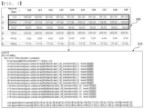
- FIG. 3 is a view illustrating a bonding parameter 300 received from a bonding parameter collection unit 110 according to an embodiment of the present invention, wherein an embodiment 310 in which the CWT calculation is substantially performed using the PyTorch API is briefly shown.
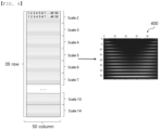
- FIG. 4 is a view showing image data 400 having a two-dimensional array of 50 x 39 as the result of CWT calculation according to an embodiment of the present invention, wherein the image data 400 having the two-dimensional array are applied to a convolutional neural network as basic training data for machine learning.
- analysis through CWT is an analysis method mainly used for failure diagnosis, which has a merit in finding discontinuity of a signal, which cannot be seen in Fourier transform, and is advantageous to analysis of an impulse signal having a large amplitude for an extremely short time.
- a neural-network-based learning algorithm adopted in the present invention adopts a deep learning model having a neural network having a multilayer structure including an input layer, a hidden layer, and an output layer, and a convolutional neural network used when spatial shape information of image data is dealt with is mainly used thereamong.
- a basic model of a general CNN is characterized by including a convolution layer configured to extract a local feature by calculating various convolutions using a filter with respect to an image, a pooling layer configured to perform a down-sampling function to reduce data size while maintaining spatial information, and a fully-connected multilayer neural network for final classification.
- the convolutional neural network in the present invention is capable of minimizing the size of a learning parameter, compared to a general multilayer neural network. As a result, it is possible to reduce the scale of the fully-connected multilayer neural network, whereby design in a structure in which learning is possible within a short time is possible. In addition, it is possible to better extract a feature from ultrasonic welding than a direct numerical value.
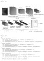
- FIG. 5 is a view showing the structure of a convolutional neural network that is implemented in the present invention.
- the convolutional neural network may be generally constituted by a convolution tier, a GAP tier, and a fully-connected tier (also referred to as an affine tier), and the convolution tier may be designed so as to have four tiers.
- the convolution tier is constituted by four layers, and different numbers of filters, i.e. 32, 64, 128, and 256 filters, are applied to the respective tiers.
- a filter having a size of 3 x 3 in a two-dimensional array is used, and a stride, which is a filter movement interval, is set to 1.
- a padding value necessary to adjust the size of an output is also set to 1 in order to output an image having the same size as an input image.
- each cell value is changed through the following equation, Leaky ReLU (rectified linear unit), which is an activation function.
- Leaky ReLU rectified linear unit
- the image changed by the above activation function halves the size of the image through pooling calculation.
- a maximum pooling (Max Pooling) technique which extracts the largest value in an area set to a 2 x 2 filter size as a representative value, is used for pooling calculation.
- 3 x 3 may be differently applied as the filter size for each tier, in addition to 2 x 2.
- a first tier of the convolution tier which is a tier in a first step of receiving training data (images) having an array of 39 x 50, generates 32 layers of convolution images using 32 filters, and performs the activation function and the pooling calculation, whereby finally 32 layers of images having an array of 20 x 25 are completed.
- 64 layers of images having a size of 10 x 13 may be constructed in a second tier
- 128 layers of images having a size of 5 x 7 may be constructed in a third tier
- 256 layers of images having a size of 3 x 4 may be constructed in a fourth tier, which is the last tier.
- the images generated in the fourth tier may not be directly connected to the fully-connected tier but a separate global average polling (GAP) tier may be provided therebetween to reduce 3 x 4 x 256 images (feature information) to a size of 256, whereby it is possible to process feature information included in the filter without loss while reducing the number of calculations.
- GAP global average polling
- the GAP may add all values of the tiers to take the average or so as to be simply processed as the sum; however, the present invention is not limited thereto.
- the result () of the GAP which is constructed as represented by the following equation, is constructed to have k one-dimensional arrays and is transmitted to fully-connected tier, where k is 256.
- F k ⁇ x , y f k x y
- FIG. 6 is a view showing an embodiment in which a convolutional neural network algorithm is implemented using the PyTorch API, wherein convolution calculation through conv2d, LeakyReLU, and MaxPool2d APIs is repeatedly performed by the designated number of tiers, and Linear API for calculation in AvgPool2d and the fully-connected tier is performed with respect to the result of convolution calculation.
- Parameter values in each API are not limited but may be variously changed as needed within the technical level of those ordinarily skilled in the art.
- the conv2d API may multiply a window type filter having a weight parameter value by input data while moving the filter at predetermined intervals and may perform calculation to obtain the total sum.
- the LeakyReLU API which is a function that sets an activation function, may be set the value of negative_slope to 0.01 such that inactivation of a negative input value to 0 is prevented and a small slope having a constant value is maintained, whereby effective learning is possible.
- the MaxPool2d API which is a function that extracts the largest value in a designated region as a representative value, constitutes a filter so as to have a size of 2 x 2, thereby reducing the image size by half to reduce the number of calculations in the fully-connected tier, sets a stride to 2, sets a padding to 1, and sets ceil_mode to FALSE, thereby constituting the same so as to have an integer number.
- the AvgPool2d API is utilized as a means to change 256 layers of 3 x 4 images, which are the result of convolution calculation of the fourth tier in FIG. .5 , to 256 one-dimensional data.
- the Linear API which is a function to perform learning through weight calculation in the fully-connected tier, may set 256 input values and 4 classification result values as parameters.
Landscapes
- Engineering & Computer Science (AREA)
- Physics & Mathematics (AREA)
- Theoretical Computer Science (AREA)
- Health & Medical Sciences (AREA)
- Life Sciences & Earth Sciences (AREA)
- General Physics & Mathematics (AREA)
- General Health & Medical Sciences (AREA)
- Evolutionary Computation (AREA)
- Artificial Intelligence (AREA)
- Computational Linguistics (AREA)
- Data Mining & Analysis (AREA)
- Molecular Biology (AREA)
- Computing Systems (AREA)
- General Engineering & Computer Science (AREA)
- Biophysics (AREA)
- Mathematical Physics (AREA)
- Software Systems (AREA)
- Biomedical Technology (AREA)
- Mechanical Engineering (AREA)
- Chemical & Material Sciences (AREA)
- Acoustics & Sound (AREA)
- Analytical Chemistry (AREA)
- Biochemistry (AREA)
- Immunology (AREA)
- Pathology (AREA)
- Chemical Kinetics & Catalysis (AREA)
- Electrochemistry (AREA)
- General Chemical & Material Sciences (AREA)
- Quality & Reliability (AREA)
- Investigating Or Analyzing Materials By The Use Of Ultrasonic Waves (AREA)
- Image Analysis (AREA)
Abstract
Description
- This application claims the benefit of priority to
Korean Patent Application No. 2021-0112586 filed on August 25, 2021 - The present invention relates to an apparatus and method for detecting various defects occurring during a wire bonding process. More particularly, the present invention relates to an apparatus and method for detecting a defect occurring during an ultrasonic wire bonding process through sampling of bonding parameters generated during the wire bonding process and machine learning of a convolutional neural network (CNN), which is a kind of deep-learning-based learning algorithm.
- There are manual macrography that checks all wires by physically pulling or picking the same and an automated inspection method using image processing as current wire bonding inspection methods performed at the time of manufacture of a cylindrical pack to which wire bonding is applied.
- These inspection methods involve problems in that the methods are inefficient as the size of the pack is increased and it is difficult to secure reliability due to physical damage, the position of a camera, resolution, and a change in surrounding environment, such as lighting.
- In addition, when separate equipment for additional electrical inspection or mechanical inspection is utilized during a bonding process, other physical and electrical damage is concerned and separate cost and time are additionally required during an inspection process, although there are advantages in terms of a wire defect, a solder defect, wire height, and the distance between adjacent wires.
- If all possible bonding parameters that may affect quality at the time of wire bonding are collected and analyzed in real time in order to perform highly reliable non-destructive inspection, therefore, it may be possible to accurately inspect errors in process and quality without physical damage.
-
Korean Patent Application Publication No. 2019-0081614 -
Japanese Patent Application Publication No. 2019-185580 -
- (Patent Document 1)
Korean Patent Application Publication No. 2019-0081614 - (Patent Document 2)
Japanese Patent Application Publication No. 2019-185580 - The present invention has been made in view of the above problems, and it is an object of the present invention to provide an apparatus and method for detecting a defect through non-destructive inspection using sampling of direct parameters that may affect wire bonding and machine learning.
- A wire bonding defect detection apparatus according to the present invention to accomplish the above objects includes an input data collection unit configured to continuously collect a plurality of ultrasonic bonding parameters by hour and to perform sampling; a data generation unit configured to apply wavelet transform to the collected data so as to convert the collected data into images having a two-dimensional array; a convolutional neural network configured to perform machine-learning training using the data generated by the data generation unit; and a defect determination unit configured to determine a defect due to the ultrasonic welding using the convolutional neural network that is trained.
- In another aspect of an embodiment, a wire bonding defect detection method according to the present invention includes collecting an input data by continuously collecting a plurality of ultrasonic bonding parameters by hour and performing sampling; generating a training data by converting the collected data into images having a two-dimensional array using wavelet transform; training a convolutional neural network with the generated training data; and determining a defect due to the ultrasonic bonding using the convolutional neural network.
- As is apparent from the above description, an apparatus capable of detecting a defect due to ultrasonic wire bonding according to the present invention and a method using the same have an effect in that bonding parameters that may affect quality of wire bonding are extracted and a defect possibility is calculated through machine learning thereof, whereby it is possible to improve efficiency due to non-destructive inspection and quality of a battery pack.
-
-
FIG. 1 is a view showing a basic structure in which a battery cell and a busbar are connected to each other by wire bonding. -
FIG. 2 is a view schematically showing the construction of a wire bonding defect detection apparatus according to an embodiment of the present invention. -
FIG. 3 is a view showing CWT calculation using the PyTorch API and parameter values that may be detected during a wire bonding process according to an embodiment of the present invention. -
FIG. 4 is a view showing image data having an array of 50 x 39 as the result of CWT calculation according to an embodiment of the present invention. -
FIG. 5 is a view showing a basic structure of a convolutional neural network according to an embodiment of the present invention. -
FIG. 6 is a view showing an embodiment of a convolutional neural network using the PyTorch API according to an embodiment of the present invention. - Now, preferred embodiments of the present invention will be described in detail with reference to the accompanying drawings such that the preferred embodiments of the present invention can be easily implemented by a person having ordinary skill in the art to which the present invention pertains.
- In describing the principle of operation of the preferred embodiments of the present invention in detail, however, a detailed description of known functions and configurations incorporated herein will be omitted when the same may obscure the subject matter of the present invention.
- In addition, the same reference numbers will be used throughout the drawings to refer to parts that perform similar functions or operations.
- When one part is said to be connected to another part throughout the specification, not only may the one part be directly connected to the other part, but also, the one part may be indirectly connected to the other part via a further part.
- In addition, that a certain element is included does not mean that other elements are excluded, but means that such elements may be further included unless mentioned otherwise.
- Hereinafter, the present invention will be described in more detail.
-
FIG. 1 is a view showing a basic structure in which anelectrode 11 of a battery cell and abusbar 12 are connected to each other by wire bonding, wherein theelectrode 11 of the battery cell and thebusbar 12 are connected to each other via analuminum wire 13 by ultrasonic welding. - During this process, most quality defects occur at a
bonding spot 14, which is a weld region to which the wire is connected. - In general, wire bonding is technology of bonding two pads spaced apart from each other to each other using a metal wire, wherein a thermal compression method, in which heat is applied for compression, and an ultrasonic welding method, in which ultrasonic waves are applied for adhesion instead of heat, are mainly used.
- The thermal compression method is a method in which the temperature of a bonding pad is increased to about 200°C in advance, the temperature of a tip of a capillary is also increased to make a wire in the form of a ball, and the wire is attached while pressure is applied to the bonding pad through the capillary.
- The ultrasonic welding method, which is a method in which ultrasonic waves are applied to a wedge (which is a wire moving mechanism similar to the capillary and forms no ball) while a wire is taken down onto a pad to attach the wire to the pad, has an advantage in that cost is low in terms of process and material. Since ultrasonic waves are used instead of heat and pressure, however, the ultrasonic welding method has a disadvantage in that tensile strength after adhesion (strength withstood when the wire is pulled after wire connection) is low although handling is easy.
- In particular, since a problem that occurs due to adoption of the ultrasonic method directly leads to a product defect, accurate detection of a defect in real time is required above all in order to secure reliability of the product.
- In addition, a parameter value necessary for ultrasonic injection may vary depending on a wire material (e.g. gold, aluminum, or copper), and defect condition may be differently set every time, which is troublesome.
- The present invention is characterized in that, during a process in which ultrasonic welding is performed to electrically connect an electrode of a battery cell and a busbar to each other via an aluminum wire, a welding defect is determined through an electrical signal applied to a bonding spot, which is a weld region, and frequency characteristic information.
-
FIG. 2 is a view schematically showing the construction of a wire bonding defect detection apparatus, wherein thedefect detection apparatus 100 is characterized by including a bondingparameter collection unit 110 configured to receive a quality measurement value from a means, such as an ultrasonicwire bonding machine 200, adata generation unit 120 for machine learning, a convolutionalneural network 130 configured to perform deep-learning-based learning, and adefect determination unit 140 configured to determine whether a defect has occurred based on the learned result. - The bonding
parameter collection unit 110 functions to sequentially receive current and voltage of an ultrasonic generator and a wire deformation measurement value according to measurement time. - The
data generation unit 120 samples data received from the bondingparameter collection unit 110 and uses a time/frequency transformation function to transform the data to be utilized by the convolutionalneural network 130 useful for image identification. - The convolutional
neural network 130 is a module that constitutes a deep learning algorithm that learns two-dimensional array data as an input. - The
defect detection unit 140 functions to analyze the final result after test data are applied to the trained convolutionalneural network 130, thereby determining whether a defect has occurred, and may provide the result of "yes/no" determining whether a defect has occurred or perform classification into groups designating the type or form of a defect; however, the present invention is not limited thereto. - In addition, there are ultrasonic generator current, ultrasonic generator voltage, wire deformation (a measured value of the height of an aluminum wire changed as the aluminum wire is melted), an ultrasonic frequency, setting voltage, and an ultrasonic phase difference as parameters that influence the wire bonding process.
- In the present invention, three thereof, i.e., the ultrasonic generator current, the ultrasonic generator voltage, and the wire deformation, are set to bonding parameters for quality measurement, and signal information, such as phase information, the ultrasonic frequency, a resonance frequency, and pressure, may be used as needed; however, the present invention is not limited thereto.
- The ultrasonic bonding parameters may be collected for a time of 10 ms to 1000 ms, preferably 50 ms to 500 ms, more preferably 100 ms to 150 ms. If the time deviates from the above range, it is not possible to secure effective parameters.
- The collection time interval of the ultrasonic bonding parameters may be 0.1 ms to 100 ms, preferably 0.5 ms to 50 ms, more preferably 1 ms to 5 ms. If the collection time interval deviates from the above range, it is not possible to secure effective parameters.
- In an embodiment of the present invention, 130 values are collected at intervals of 1 ms for 130 ms as input data, which are the ultrasonic bonding parameters. Thereamong, 50 data may preferably be sampled. If more than 50 data are sampled, there is a problem in that there is no advantage in the aspect of performance and learning time exponentially increases.
- In the sampling method, arbitrary selection is performed or only data for initial 50 ms are extracted, arranged, and are converted into a value xnew from 0 to 1 through the following equation, which is minimum-maximum (MinMax) scaling.

- Continuous wavelet transform (CWT) is performed to reconstruct the converted value xnew in the time domain.
- In the present invention, CWT performs overlapping with an original signal using Mexican Hat, which is a waveform transform function, and generates 13 two-dimensional images while changing a scale value, which is one of wavelet parameters, to 2 to 14. The scale values are not limited to 13 and various changes may be performed as needed. In addition, a Bump, Morlet, or Paul function may be used as the waveform transform function, in addition to the Mexican Hat function.
-
FIG. 3 is a view illustrating abonding parameter 300 received from a bondingparameter collection unit 110 according to an embodiment of the present invention, wherein anembodiment 310 in which the CWT calculation is substantially performed using the PyTorch API is briefly shown. -
FIG. 4 is a view showingimage data 400 having a two-dimensional array of 50 x 39 as the result of CWT calculation according to an embodiment of the present invention, wherein theimage data 400 having the two-dimensional array are applied to a convolutional neural network as basic training data for machine learning. - In the present invention, analysis through CWT is an analysis method mainly used for failure diagnosis, which has a merit in finding discontinuity of a signal, which cannot be seen in Fourier transform, and is advantageous to analysis of an impulse signal having a large amplitude for an extremely short time.
- A neural-network-based learning algorithm adopted in the present invention adopts a deep learning model having a neural network having a multilayer structure including an input layer, a hidden layer, and an output layer, and a convolutional neural network used when spatial shape information of image data is dealt with is mainly used thereamong.
- A basic model of a general CNN is characterized by including a convolution layer configured to extract a local feature by calculating various convolutions using a filter with respect to an image, a pooling layer configured to perform a down-sampling function to reduce data size while maintaining spatial information, and a fully-connected multilayer neural network for final classification.
- The convolutional neural network in the present invention is capable of minimizing the size of a learning parameter, compared to a general multilayer neural network. As a result, it is possible to reduce the scale of the fully-connected multilayer neural network, whereby design in a structure in which learning is possible within a short time is possible. In addition, it is possible to better extract a feature from ultrasonic welding than a direct numerical value.
-
FIG. 5 is a view showing the structure of a convolutional neural network that is implemented in the present invention. - As can be seen from
FIG. 5 , the convolutional neural network may be generally constituted by a convolution tier, a GAP tier, and a fully-connected tier (also referred to as an affine tier), and the convolution tier may be designed so as to have four tiers. - The convolution tier is constituted by four layers, and different numbers of filters, i.e. 32, 64, 128, and 256 filters, are applied to the respective tiers.
- In the convolution tier, a filter having a size of 3 x 3 in a two-dimensional array is used, and a stride, which is a filter movement interval, is set to 1. In addition, a padding value necessary to adjust the size of an output is also set to 1 in order to output an image having the same size as an input image.
- In addition, each cell value is changed through the following equation, Leaky ReLU (rectified linear unit), which is an activation function.

- The image changed by the above activation function halves the size of the image through pooling calculation.
- In the present invention, a maximum pooling (Max Pooling) technique, which extracts the largest value in an area set to a 2 x 2 filter size as a representative value, is used for pooling calculation.
- In addition, 3 x 3 may be differently applied as the filter size for each tier, in addition to 2 x 2.
- A first tier of the convolution tier, which is a tier in a first step of receiving training data (images) having an array of 39 x 50, generates 32 layers of convolution images using 32 filters, and performs the activation function and the pooling calculation, whereby finally 32 layers of images having an array of 20 x 25 are completed.
- When the above process is repeated, 64 layers of images having a size of 10 x 13 may be constructed in a second tier, 128 layers of images having a size of 5 x 7 may be constructed in a third tier, and 256 layers of images having a size of 3 x 4 may be constructed in a fourth tier, which is the last tier.
- The images generated in the fourth tier may not be directly connected to the fully-connected tier but a separate global average polling (GAP) tier may be provided therebetween to reduce 3 x 4 x 256 images (feature information) to a size of 256, whereby it is possible to process feature information included in the filter without loss while reducing the number of calculations.
- The GAP may add all values of the tiers to take the average or so as to be simply processed as the sum; however, the present invention is not limited thereto.
- The result () of the GAP, which is constructed as represented by the following equation, is constructed to have k one-dimensional arrays and is transmitted to fully-connected tier, where k is 256.

-
FIG. 6 is a view showing an embodiment in which a convolutional neural network algorithm is implemented using the PyTorch API, wherein convolution calculation through conv2d, LeakyReLU, and MaxPool2d APIs is repeatedly performed by the designated number of tiers, and Linear API for calculation in AvgPool2d and the fully-connected tier is performed with respect to the result of convolution calculation. Parameter values in each API are not limited but may be variously changed as needed within the technical level of those ordinarily skilled in the art. - The conv2d API may multiply a window type filter having a weight parameter value by input data while moving the filter at predetermined intervals and may perform calculation to obtain the total sum.
- The LeakyReLU API, which is a function that sets an activation function, may be set the value of negative_slope to 0.01 such that inactivation of a negative input value to 0 is prevented and a small slope having a constant value is maintained, whereby effective learning is possible.
- The MaxPool2d API, which is a function that extracts the largest value in a designated region as a representative value, constitutes a filter so as to have a size of 2 x 2, thereby reducing the image size by half to reduce the number of calculations in the fully-connected tier, sets a stride to 2, sets a padding to 1, and sets ceil_mode to FALSE, thereby constituting the same so as to have an integer number.
- The AvgPool2d API is utilized as a means to change 256 layers of 3 x 4 images, which are the result of convolution calculation of the fourth tier in
FIG. .5 , to 256 one-dimensional data. - The Linear API, which is a function to perform learning through weight calculation in the fully-connected tier, may set 256 input values and 4 classification result values as parameters.
- Although the specific details of the present invention have been described in detail, those skilled in the art will appreciate that the detailed description thereof discloses only preferred embodiments of the present invention and thus does not limit the scope of the present invention. Accordingly, those skilled in the art will appreciate that various changes and modifications are possible, without departing from the category and technical idea of the present invention, and it will be obvious that such changes and modifications fall within the scope of the appended claims.
-
- 11: Electrode
- 12: Busbar
- 13: Wire
- 14: Bonding spot
- 100: Defect detection apparatus
- 110: Bonding parameter collection unit
- 120: Data generation unit
- 130: Convolutional neural network
- 140: Defect determination unit
- 200: Ultrasonic wire bonding machine
- 300: Bonding parameter
- 400: Training image data
Claims (12)
- An apparatus for detecting a bonding defect by ultrasonic wire bonding, the bonding defect occurring between a battery cell and a busbar connected to each other via a wire through ultrasonic bonding, the apparatus comprising:an input data collection unit configured to continuously collect a plurality of ultrasonic bonding parameters by hour and to perform sampling;a data generation unit configured to apply wavelet transform to the collected data so as to convert the collected data into images having a two-dimensional array;a convolutional neural network configured to perform machine-learning training using the data generated by the data generation unit; anda defect determination unit configured to determine a defect due to the bonding using the convolutional neural network that is trained.
- The apparatus according to claim 1, wherein the plurality of ultrasonic bonding parameters comprise an ultrasonic generator current, an ultrasonic generator voltage, and a measured value of wire deformation.
- The apparatus according to claim 1, wherein the wavelet transform is for converting the input data into a value of 0 to 1 through minimum-maximum scaling and generating training data having a two-dimensional array through a scale value of 2 or more using a Mexican Hat waveform transform function.
- The apparatus according to claim 1, wherein the convolutional neural network comprises four convolution layers, a GAP layer, and a fully-connected layer.
- The apparatus according to claim 1, wherein the ultrasonic bonding parameters are collected for a time of 10 ms to 1000 ms.
- The apparatus according to claim 1, wherein the ultrasonic bonding parameters are collected at intervals of 0.1 ms to 100 ms.
- A method of detecting a bonding defect by ultrasonic wire bonding, the bonding defect occurring between a battery cell and a busbar connected to each other via a wire through ultrasonic bonding, the method comprising:(a) collecting an input data by continuously collecting a plurality of ultrasonic bonding parameters by hour and performing sampling;(b) generating a training data by converting the collected data into images having a two-dimensional array using wavelet transform;(c) training a convolutional neural network with the generated training data; and(d) determining a defect due to the ultrasonic bonding using the convolutional neural network.
- The method according to claim 7, wherein the wavelet transform of step (b) is wavelet transform configured to convert the input data into a value of 0 to 1 through minimum-maximum scaling and to generate training data having a two-dimensional array through a scale value of 2 or more using a Mexican Hat waveform transform function.
- The method according to claim 7, wherein step (c) comprises performing convolution calculation with respect to the images having the two-dimensional array generated in step (b) using a 2 x 2 or 3 x 3 filter and performing calculation through an activation function and pooling to generate 256 one-dimensional data.
- The method according to claim 7 or 8, wherein the plurality of ultrasonic bonding parameters comprise an ultrasonic generator current, an ultrasonic generator voltage, and a measured value of wire deformation.
- A battery pack configured to have a welding defect between a battery cell and a busbar detected using the apparatus according to any one of claims 1 to 6.
- A device comprising the battery pack according to claim 11.
Applications Claiming Priority (2)
| Application Number | Priority Date | Filing Date | Title |
|---|---|---|---|
| KR1020210112586A KR102944779B1 (en) | 2021-08-25 | 2021-08-25 | Fault detection device of wire bonding process and method thereof |
| PCT/KR2022/012614 WO2023027490A1 (en) | 2021-08-25 | 2022-08-24 | Device for detecting defect in wire bonding and operation method thereof |
Publications (2)
| Publication Number | Publication Date |
|---|---|
| EP4299236A1 true EP4299236A1 (en) | 2024-01-03 |
| EP4299236A4 EP4299236A4 (en) | 2024-11-06 |
Family
ID=85321900
Family Applications (1)
| Application Number | Title | Priority Date | Filing Date |
|---|---|---|---|
| EP22861699.1A Pending EP4299236A4 (en) | 2021-08-25 | 2022-08-24 | WIRE CONNECTION FAULT DETECTION DEVICE AND OPERATING METHOD THEREOF |
Country Status (5)
| Country | Link |
|---|---|
| US (1) | US12601713B2 (en) |
| EP (1) | EP4299236A4 (en) |
| KR (1) | KR102944779B1 (en) |
| CN (1) | CN116981538A (en) |
| WO (1) | WO2023027490A1 (en) |
Family Cites Families (25)
| Publication number | Priority date | Publication date | Assignee | Title |
|---|---|---|---|---|
| DE102007054626A1 (en) | 2007-11-12 | 2009-05-14 | Hesse & Knipps Gmbh | Method and apparatus for ultrasonic bonding |
| CN101241872B (en) | 2008-01-22 | 2010-06-09 | 西安交通大学 | A Distributed Ultrasonic Wire Bonding Quality Online Inspection System |
| US20100010780A1 (en) * | 2008-07-10 | 2010-01-14 | The Hong Kong Polytechnic University | Method for signal denoising using continuous wavelet transform |
| KR101033416B1 (en) * | 2009-11-30 | 2011-05-11 | 재단법인대구경북과학기술원 | Pulse diagnosis robot system and pulse diagnosis method using the same |
| KR20110108950A (en) | 2010-03-30 | 2011-10-06 | 울산대학교 산학협력단 | Fault Diagnosis Device Using Neural Network and Feature Point and Its Fault Diagnosis Method |
| US9966584B2 (en) | 2013-03-11 | 2018-05-08 | Atieva, Inc. | Bus bar for battery packs |
| KR20150078086A (en) | 2013-12-30 | 2015-07-08 | 에이치엘그린파워 주식회사 | Method for welding portion of battery cell of eco-friendly vehicle |
| CN106870957B (en) | 2017-03-21 | 2019-02-05 | 东北大学 | A Feature Extraction Method for MFL Signals of Pipeline Defects |
| US10520947B2 (en) * | 2017-03-27 | 2019-12-31 | Uatc, Llc | Machine learning for event detection and classification in autonomous vehicles |
| KR102009572B1 (en) | 2017-11-07 | 2019-08-09 | 경일대학교산학협력단 | Apparatus and method for estimating a quality of spot welding |
| CN107894564B (en) | 2017-11-09 | 2020-02-18 | 合肥工业大学 | A Fault Diagnosis Method for Analog Circuits Based on Cross Wavelet Features |
| KR102007494B1 (en) | 2017-12-29 | 2019-08-05 | 주식회사 신영 | System for inspecting welding quality of weld zone using ultrasonic |
| JP2019185580A (en) | 2018-04-16 | 2019-10-24 | アズビル株式会社 | Device and method for detecting abnormality |
| KR102209401B1 (en) * | 2018-12-17 | 2021-02-01 | 주식회사 포스코 | Apparatus and method for fault diagnosis of gearbox using cnn |
| JP7121911B2 (en) | 2019-01-29 | 2022-08-19 | トヨタ自動車株式会社 | WELDING QUALITY INSPECTION METHOD AND WELDING QUALITY INSPECTION DEVICE |
| KR102210159B1 (en) | 2019-07-08 | 2021-02-01 | 한밭대학교 산학협력단 | Wire mismatch detection device and method using convolutional neural network and fault localization based on time-frequency domain reflectometry |
| CN112235583B (en) | 2019-07-15 | 2021-12-24 | 华为技术有限公司 | Image coding and decoding method and device based on wavelet transformation |
| JP2021018849A (en) * | 2019-07-17 | 2021-02-15 | オムロン株式会社 | Prediction device, data generation device, method for controlling prediction device, method for controlling data generation device, information processing program, and recording medium |
| KR102919062B1 (en) | 2019-07-30 | 2026-01-27 | 주식회사 엘지에너지솔루션 | Method for testing resistance welding part of battery using eddy current signal |
| US11906593B2 (en) | 2019-10-31 | 2024-02-20 | Keysight Technologies, Inc. | Method and system for testing the structural integrity of a metal joint |
| CN111047225B (en) | 2020-01-10 | 2021-03-23 | 惠州光弘科技股份有限公司 | SMT surface mounting component welding spot quality evaluation method based on edge side model processing |
| US20210249739A1 (en) | 2020-02-06 | 2021-08-12 | Samsung Sdi Co., Ltd. | Cell connection unit for a battery module |
| KR102863614B1 (en) | 2020-03-05 | 2025-09-22 | 에이치디현대인프라코어 주식회사 | Contruction machine and method for controlling the gauge panel for contruction machine |
| CN112232400B (en) * | 2020-10-12 | 2023-06-20 | 太原科技大学 | An Ultrasonic Defect Detection Method for Stainless Steel Welds Based on Deep and Shallow Feature Fusion |
| CN113111570A (en) * | 2021-03-09 | 2021-07-13 | 武汉大学 | Lead bonding quality prediction control method based on machine learning |
-
2021
- 2021-08-25 KR KR1020210112586A patent/KR102944779B1/en active Active
-
2022
- 2022-08-24 US US18/281,718 patent/US12601713B2/en active Active
- 2022-08-24 CN CN202280021280.7A patent/CN116981538A/en active Pending
- 2022-08-24 EP EP22861699.1A patent/EP4299236A4/en active Pending
- 2022-08-24 WO PCT/KR2022/012614 patent/WO2023027490A1/en not_active Ceased
Also Published As
| Publication number | Publication date |
|---|---|
| US20240159713A1 (en) | 2024-05-16 |
| EP4299236A4 (en) | 2024-11-06 |
| KR102944779B1 (en) | 2026-03-27 |
| US12601713B2 (en) | 2026-04-14 |
| CN116981538A (en) | 2023-10-31 |
| KR20230030405A (en) | 2023-03-06 |
| WO2023027490A1 (en) | 2023-03-02 |
Similar Documents
| Publication | Publication Date | Title |
|---|---|---|
| Tibaduiza et al. | A study of two unsupervised data driven statistical methodologies for detecting and classifying damages in structural health monitoring | |
| TW202043954A (en) | Apparatus and method of detecting fault | |
| KR102209401B1 (en) | Apparatus and method for fault diagnosis of gearbox using cnn | |
| Liu et al. | MPNet: A lightweight fault diagnosis network for rotating machinery | |
| JP2012018066A (en) | Device for inspecting abnormality | |
| Kim et al. | Bi-directional convolutional recurrent reconstructive network for welding defect detection | |
| CN115597868A (en) | A Bearing Fault Classification Method Based on Wavelet Signal Processing and Deep Learning | |
| CN112946081A (en) | Ultrasonic imaging method based on defect multi-feature intelligent extraction and fusion | |
| CN115856088A (en) | High-voltage cable lead sealing quality detection system based on phased array ultrasonic imaging technology | |
| KR20210077496A (en) | Equipment failure prediction system having multi-channel sensors for receiving acoustic signals in the ultrasonic band | |
| CN120064941A (en) | Method and system for testing electronic product | |
| Zhang et al. | Reinforcement learning based neural architecture search for flaw detection in intelligent ultrasonic imaging NDE system | |
| Song et al. | Unsupervised temperature-compensated damage localization method based on damage to baseline autoencoder and delay-based probabilistic imaging | |
| US12601713B2 (en) | Wire bonding defect detection apparatus and operation method thereof | |
| WO2024092345A1 (en) | Non-destructive test (ndt) flaw and anomaly detection | |
| CN113807267A (en) | Evaluation method of discharge severity of suspended insulators based on ultraviolet video and deep learning | |
| CN120628809B (en) | Titanium alloy wire performance detection method, equipment and system | |
| CN119086721B (en) | Plastic product strength detection method and device based on non-contact measurement | |
| CN120629285A (en) | A method and system for detecting insulation damage of automobile wiring harness conductors | |
| CN120064467A (en) | IGBT bonding wire fault detection method and system based on stress wave two-dimensional image signals | |
| CN113256613A (en) | Pipeline damage data feature recognition model and method | |
| CN117909816A (en) | Method and system for identifying cross-working condition fault degree of rotary mechanical equipment | |
| Yin et al. | Cable fault location with convolutional neural network and attention mechanism | |
| CN115876249B (en) | A flexible spiral sensor and method for detecting cracks in transformer lead bushings. | |
| CN120985164B (en) | Battery tab welding quality detection system and method |
Legal Events
| Date | Code | Title | Description |
|---|---|---|---|
| STAA | Information on the status of an ep patent application or granted ep patent |
Free format text: STATUS: THE INTERNATIONAL PUBLICATION HAS BEEN MADE |
|
| PUAI | Public reference made under article 153(3) epc to a published international application that has entered the european phase |
Free format text: ORIGINAL CODE: 0009012 |
|
| STAA | Information on the status of an ep patent application or granted ep patent |
Free format text: STATUS: REQUEST FOR EXAMINATION WAS MADE |
|
| 17P | Request for examination filed |
Effective date: 20230929 |
|
| AK | Designated contracting states |
Kind code of ref document: A1 Designated state(s): AL AT BE BG CH CY CZ DE DK EE ES FI FR GB GR HR HU IE IS IT LI LT LU LV MC MK MT NL NO PL PT RO RS SE SI SK SM TR |
|
| A4 | Supplementary search report drawn up and despatched |
Effective date: 20241009 |
|
| RIC1 | Information provided on ipc code assigned before grant |
Ipc: H01L 23/00 20060101ALI20241002BHEP Ipc: G06N 3/0464 20230101ALI20241002BHEP Ipc: G06N 3/048 20230101ALI20241002BHEP Ipc: B23K 101/36 20060101ALI20241002BHEP Ipc: G06N 3/04 20230101ALI20241002BHEP Ipc: G06N 3/08 20230101ALI20241002BHEP Ipc: B23K 20/10 20060101ALI20241002BHEP Ipc: B23K 31/12 20060101AFI20241002BHEP |
|
| DAV | Request for validation of the european patent (deleted) | ||
| DAX | Request for extension of the european patent (deleted) | ||
| STAA | Information on the status of an ep patent application or granted ep patent |
Free format text: STATUS: EXAMINATION IS IN PROGRESS |
|
| 17Q | First examination report despatched |
Effective date: 20260210 |