EP4299217A1 - Three-dimensional powder bed fusion additive manufacturing apparatus - Google Patents
Three-dimensional powder bed fusion additive manufacturing apparatus Download PDFInfo
- Publication number
- EP4299217A1 EP4299217A1 EP23177180.9A EP23177180A EP4299217A1 EP 4299217 A1 EP4299217 A1 EP 4299217A1 EP 23177180 A EP23177180 A EP 23177180A EP 4299217 A1 EP4299217 A1 EP 4299217A1
- Authority
- EP
- European Patent Office
- Prior art keywords
- pbf
- dimensional
- electron beam
- electron
- differential evacuation
- Prior art date
- Legal status (The legal status is an assumption and is not a legal conclusion. Google has not performed a legal analysis and makes no representation as to the accuracy of the status listed.)
- Pending
Links
Images





Classifications
-
- B—PERFORMING OPERATIONS; TRANSPORTING
- B22—CASTING; POWDER METALLURGY
- B22F—WORKING METALLIC POWDER; MANUFACTURE OF ARTICLES FROM METALLIC POWDER; MAKING METALLIC POWDER; APPARATUS OR DEVICES SPECIALLY ADAPTED FOR METALLIC POWDER
- B22F10/00—Additive manufacturing of workpieces or articles from metallic powder
- B22F10/20—Direct sintering or melting
- B22F10/28—Powder bed fusion, e.g. selective laser melting [SLM] or electron beam melting [EBM]
-
- B—PERFORMING OPERATIONS; TRANSPORTING
- B22—CASTING; POWDER METALLURGY
- B22F—WORKING METALLIC POWDER; MANUFACTURE OF ARTICLES FROM METALLIC POWDER; MAKING METALLIC POWDER; APPARATUS OR DEVICES SPECIALLY ADAPTED FOR METALLIC POWDER
- B22F12/00—Apparatus or devices specially adapted for additive manufacturing; Auxiliary means for additive manufacturing; Combinations of additive manufacturing apparatus or devices with other processing apparatus or devices
- B22F12/40—Radiation means
- B22F12/41—Radiation means characterised by the type, e.g. laser or electron beam
-
- B—PERFORMING OPERATIONS; TRANSPORTING
- B22—CASTING; POWDER METALLURGY
- B22F—WORKING METALLIC POWDER; MANUFACTURE OF ARTICLES FROM METALLIC POWDER; MAKING METALLIC POWDER; APPARATUS OR DEVICES SPECIALLY ADAPTED FOR METALLIC POWDER
- B22F12/00—Apparatus or devices specially adapted for additive manufacturing; Auxiliary means for additive manufacturing; Combinations of additive manufacturing apparatus or devices with other processing apparatus or devices
- B22F12/90—Means for process control, e.g. cameras or sensors
-
- B—PERFORMING OPERATIONS; TRANSPORTING
- B29—WORKING OF PLASTICS; WORKING OF SUBSTANCES IN A PLASTIC STATE IN GENERAL
- B29C—SHAPING OR JOINING OF PLASTICS; SHAPING OF MATERIAL IN A PLASTIC STATE, NOT OTHERWISE PROVIDED FOR; AFTER-TREATMENT OF THE SHAPED PRODUCTS, e.g. REPAIRING
- B29C64/00—Additive manufacturing, i.e. manufacturing of three-dimensional [3D] objects by additive deposition, additive agglomeration or additive layering, e.g. by 3D printing, stereolithography or selective laser sintering
- B29C64/10—Processes of additive manufacturing
- B29C64/141—Processes of additive manufacturing using only solid materials
- B29C64/153—Processes of additive manufacturing using only solid materials using layers of powder being selectively joined, e.g. by selective laser sintering or melting
-
- B—PERFORMING OPERATIONS; TRANSPORTING
- B29—WORKING OF PLASTICS; WORKING OF SUBSTANCES IN A PLASTIC STATE IN GENERAL
- B29C—SHAPING OR JOINING OF PLASTICS; SHAPING OF MATERIAL IN A PLASTIC STATE, NOT OTHERWISE PROVIDED FOR; AFTER-TREATMENT OF THE SHAPED PRODUCTS, e.g. REPAIRING
- B29C64/00—Additive manufacturing, i.e. manufacturing of three-dimensional [3D] objects by additive deposition, additive agglomeration or additive layering, e.g. by 3D printing, stereolithography or selective laser sintering
- B29C64/20—Apparatus for additive manufacturing; Details thereof or accessories therefor
- B29C64/264—Arrangements for irradiation
- B29C64/268—Arrangements for irradiation using laser beams; using electron beams [EB]
-
- B—PERFORMING OPERATIONS; TRANSPORTING
- B29—WORKING OF PLASTICS; WORKING OF SUBSTANCES IN A PLASTIC STATE IN GENERAL
- B29C—SHAPING OR JOINING OF PLASTICS; SHAPING OF MATERIAL IN A PLASTIC STATE, NOT OTHERWISE PROVIDED FOR; AFTER-TREATMENT OF THE SHAPED PRODUCTS, e.g. REPAIRING
- B29C64/00—Additive manufacturing, i.e. manufacturing of three-dimensional [3D] objects by additive deposition, additive agglomeration or additive layering, e.g. by 3D printing, stereolithography or selective laser sintering
- B29C64/30—Auxiliary operations or equipment
- B29C64/364—Conditioning of environment
- B29C64/371—Conditioning of environment using an environment other than air, e.g. inert gas
-
- B—PERFORMING OPERATIONS; TRANSPORTING
- B33—ADDITIVE MANUFACTURING TECHNOLOGY
- B33Y—ADDITIVE MANUFACTURING, i.e. MANUFACTURING OF THREE-DIMENSIONAL [3D] OBJECTS BY ADDITIVE DEPOSITION, ADDITIVE AGGLOMERATION OR ADDITIVE LAYERING, e.g. BY 3D PRINTING, STEREOLITHOGRAPHY OR SELECTIVE LASER SINTERING
- B33Y10/00—Processes of additive manufacturing
-
- B—PERFORMING OPERATIONS; TRANSPORTING
- B33—ADDITIVE MANUFACTURING TECHNOLOGY
- B33Y—ADDITIVE MANUFACTURING, i.e. MANUFACTURING OF THREE-DIMENSIONAL [3D] OBJECTS BY ADDITIVE DEPOSITION, ADDITIVE AGGLOMERATION OR ADDITIVE LAYERING, e.g. BY 3D PRINTING, STEREOLITHOGRAPHY OR SELECTIVE LASER SINTERING
- B33Y30/00—Apparatus for additive manufacturing; Details thereof or accessories therefor
-
- B—PERFORMING OPERATIONS; TRANSPORTING
- B22—CASTING; POWDER METALLURGY
- B22F—WORKING METALLIC POWDER; MANUFACTURE OF ARTICLES FROM METALLIC POWDER; MAKING METALLIC POWDER; APPARATUS OR DEVICES SPECIALLY ADAPTED FOR METALLIC POWDER
- B22F10/00—Additive manufacturing of workpieces or articles from metallic powder
- B22F10/30—Process control
- B22F10/31—Calibration of process steps or apparatus settings, e.g. before or during manufacturing
-
- B—PERFORMING OPERATIONS; TRANSPORTING
- B22—CASTING; POWDER METALLURGY
- B22F—WORKING METALLIC POWDER; MANUFACTURE OF ARTICLES FROM METALLIC POWDER; MAKING METALLIC POWDER; APPARATUS OR DEVICES SPECIALLY ADAPTED FOR METALLIC POWDER
- B22F12/00—Apparatus or devices specially adapted for additive manufacturing; Auxiliary means for additive manufacturing; Combinations of additive manufacturing apparatus or devices with other processing apparatus or devices
- B22F12/70—Gas flow means
-
- B—PERFORMING OPERATIONS; TRANSPORTING
- B22—CASTING; POWDER METALLURGY
- B22F—WORKING METALLIC POWDER; MANUFACTURE OF ARTICLES FROM METALLIC POWDER; MAKING METALLIC POWDER; APPARATUS OR DEVICES SPECIALLY ADAPTED FOR METALLIC POWDER
- B22F2201/00—Treatment under specific atmosphere
- B22F2201/20—Use of vacuum
-
- Y—GENERAL TAGGING OF NEW TECHNOLOGICAL DEVELOPMENTS; GENERAL TAGGING OF CROSS-SECTIONAL TECHNOLOGIES SPANNING OVER SEVERAL SECTIONS OF THE IPC; TECHNICAL SUBJECTS COVERED BY FORMER USPC CROSS-REFERENCE ART COLLECTIONS [XRACs] AND DIGESTS
- Y02—TECHNOLOGIES OR APPLICATIONS FOR MITIGATION OR ADAPTATION AGAINST CLIMATE CHANGE
- Y02P—CLIMATE CHANGE MITIGATION TECHNOLOGIES IN THE PRODUCTION OR PROCESSING OF GOODS
- Y02P10/00—Technologies related to metal processing
- Y02P10/25—Process efficiency
Definitions
- the present invention relates to a three-dimensional powder bed fusion additive manufacturing (PBF-AM) apparatus that builds an object by building up layers, in each of which a powder material is thinly spread, on a layer-by-layer basis.
- PPF-AM powder bed fusion additive manufacturing
- a powder material is spread, on a layer-by-layer basis, on a base plate installed on an upper surface of a stage.
- a heating mechanism including an electron beam or a laser.
- layers of the powder material are built up on a layer-by-layer basis in a height direction (Z direction) to form a built object (see, for example, Patent Literature 1).
- an electron gun chamber accommodating the electron gun is required to have a high degree of vacuum in order to reduce electric discharge.
- the inside of the electron gun chamber is evacuated by a vacuum pump in order to protect an electron source from residual gas that causes a chemical reaction such as oxidation.
- the electron gun chamber and the build chamber physically communicate with each other by a beam path through which the electron beam passes. Then, not only the electron beam but also gas in the build chamber passes through the beam path. Therefore, the gas passes through the beam path from the build chamber having a low degree of vacuum to the electron gun chamber having a high degree of vacuum.
- a differential evacuation system in which different vacuum pumps are connected to the electron gun chamber and the build chamber, and gas in the electron gun chamber and the build chamber are evacuated by the different vacuum pumps.
- FIG. 7 is an explanatory diagram illustrating a relationship between a degree of vacuum in an electron gun chamber 102 and a degree of vacuum in a build chamber 103.
- a first vacuum pump 105 is connected to the electron gun chamber 102
- a second vacuum pump 106 is connected to the build chamber 103.
- the electron gun chamber 102 and the build chamber 103 physically communicate with each other through a beam path through which an electron beam passes. Then, gas in the build chamber 103 flows into the electron gun chamber 102 through the beam path.
- the electron gun chamber 102 can be maintained at a high degree of vacuum.
- the gas flow rate Q can be reduced by reducing conductance C to be small as illustrated in Formula 1.
- Patent Literature 1 JP 2015-168228 A
- An object of the present invention is to provide a three-dimensional PBF-AM apparatus capable of increasing a degree of vacuum of an electron gun chamber in consideration of the above problems.
- a three-dimensional PBF-AM apparatus of the present invention includes an electron gun chamber accommodating an electron gun, a build chamber accommodating a build unit to be irradiated with an electron beam emitted from the electron gun, a first vacuum pump, a second vacuum pump, and a beam path.
- the first vacuum pump evacuates gas in the electron gun chamber.
- the second vacuum pump evacuates gas in the build chamber.
- the electron beam path communicates the electron gun chamber and the build chamber, and the electron beam passes through the electron beam path.
- the three-dimensional PBF-AM apparatus includes a differential evacuation aperture, a focusing lens, and an axis adjustment mechanism.
- the differential evacuation aperture is provided in the beam path to divide an internal space of the beam path into two, and has a restriction hole through which the electron beam can pass.
- the focusing lens focuses the electron beam emitted from the electron gun using the restriction hole of the differential evacuation aperture.
- the axis adjustment mechanism adjusts a trajectory of the electron beam or positions of the focusing lens and the differential evacuation aperture such that an optical axis of the electron beam passes through both the center of the restriction hole of the differential evacuation aperture and the center of the focusing lens.
- the degree of vacuum of the electron gun chamber can be increased.
- FIG. 1 is a cross-sectional diagram schematically illustrating the three-dimensional PBF-AM apparatus 1 of the present example.
- the three-dimensional PBF-AM apparatus 1 illustrated in FIG. 1 is an apparatus that irradiates a powder material made of a metal powder of, for example, titanium, aluminum, iron, or the like with an electron beam L1 to melt the powder material, and builds up layers, in each of which the powder material is solidified, to build a three-dimensional object.
- the electron optical chamber 4 includes an objective lens 11, a focusing lens 12, an axis adjustment mechanism 13, and a differential evacuation aperture (hereinafter, referred to as "differential evacuation AP") 14.
- the objective lens 11, the focusing lens 12, and a coil that generates a magnetic field are included.
- the differential evacuation AP14 is disposed between the objective lens 11 and the focusing lens 12 to be described later in the beam path 8.
- a restriction hole 14a through which the electron beam L1 can pass is formed in the differential evacuation AP14.
- the differential evacuation AP14 divides an internal space of the beam path 8 into two, that is, a space on a side of the electron gun chamber 2 and a space on a side of the build chamber 3.
- the differential evacuation AP14 is provided, whereby gas hardly flows from the space on the side of the build chamber 3 to the space on the side of the electron gun chamber 2. In other words, conductance C can be reduced by the differential evacuation AP14, and the gas can be prevented from passing through the beam path 8 from the build chamber 3 and flowing into the electron gun chamber 2. This, as a result, makes it possible to set a degree of vacuum of the electron gun chamber 2 to a desired degree of vacuum without using a vacuum pump having high evacuation performance as the first vacuum pump 5.
- the opening diameter of the restriction hole 14a of the differential evacuation AP14 can be further reduced.
- the conductance C can be further reduced by the differential evacuation AP14, and it is possible to enhance the effect of preventing the inflow of the gas from the space on the side of the build chamber 3 to the space on the side of the electron gun chamber 2.
- the axis adjustment mechanism 13 is disposed between the focusing lens 12 and the electron gun chamber 2, that is, on the upstream (electron source 10) side of the electron beam L1 from the focusing lens 12.
- the axis adjustment mechanism 13 includes a first adjustment unit 13a and a second adjustment unit 13b.
- the first adjustment unit 13a and the second adjustment unit 13b are disposed along an optical axis L2 of the electron beam L1.
- the first adjustment unit 13a and the second adjustment unit 13b are electromagnetic deflectors that generate a magnetic field.
- the first adjustment unit 13a and the second adjustment unit 13b for example, saddle-type coils or other various electromagnetic deflectors are applied.
- the first adjustment unit 13a and the second adjustment unit 13b adjust a trajectory of the electron beam L1 so that the trajectory of the electron beam L1 coincides with a magnetic field center of the focusing lens 12 and the center of the opening of the restriction hole 14a of the differential evacuation AP14 in a direction in which the optical axis L2 of the electron beam L1 that has passed through the anode 17 is orthogonal to the optical axis L2 (hereinafter, referred to as second direction).
- the axis adjustment mechanism 13 causes the entire electron beam L1 emitted from the electron source 10 to passes through the restriction hole 14a of the differential evacuation AP14.
- two adjustment units that are the first adjustment unit 13a and the second adjustment unit 13b are provided as the axis adjustment mechanism 13, whereby the optical axis L2 can be adjusted to pass through two centers that are the center of the focusing lens 12 and the center of the restriction hole 14a.
- the output of the electron beam L1 emitted from the electron source 10 changes according to a voltage applied to the Wehnelt 18.
- the control device can control the focusing lens 12 and the axis adjustment mechanism 13 according to the output of the electron beam L1. Consequently, even in a case where the output of the electron beam L1 changes, the optical axis L2 of the electron beam L1 can be caused to pass through the magnetic field center of the focusing lens 12 and the center of the opening of the restriction hole 14a of the differential evacuation AP14.
- a focal position of the focusing lens 12 can be aligned with a position of the center of the opening of the restriction hole 14a of the differential evacuation AP14.
- FIG. 2 is a schematic configuration diagram illustrating the three-dimensional PBF-AM apparatus 1A according to a second embodiment example.
- the three-dimensional PBF-AM apparatus 1A includes a focusing lens 22 and an axis adjustment mechanism 23.
- the focusing lens 22 according to the second embodiment example is an electrostatic lens
- the axis adjustment mechanism 23 is an electrostatic deflector.
- the focusing lens 22 and the axis adjustment mechanism 23 include a plurality of electrodes facing each other to which a voltage is applied. Then, the voltage is applied to the electrodes to generate an electric field in a beam path 8, whereby the focusing lens 22 and the axis adjustment mechanism 23 controls the focusing and trajectory of an electron beam L1.
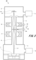
- FIG. 3 is a schematic configuration diagram illustrating the three-dimensional PBF-AM apparatus 1B according to the third embodiment example.
- the three-dimensional PBF-AM apparatus 1B according to the third embodiment example is different from the three-dimensional PBF-AM apparatus 1 according to the first embodiment example in a configuration of an axis adjustment mechanism. Therefore, parts in common with those of the three-dimensional PBF-AM apparatus 1 according to the first embodiment example, and redundant description will be omitted.
- the first axis adjustment mechanism 32 adjusts a position of the focusing lens 12 so that the optical axis L2 of the electron beam L1 passes through the center of the focusing lens 12.
- the second axis adjustment mechanism 33 supports the differential evacuation AP14 in a manner such that the differential evacuation AP14 is movable along the second direction. Then, the second axis adjustment mechanism 33 adjusts a position of the differential evacuation AP14 so that the optical axis L2 of the electron beam L1 passes through the center of a restriction hole 14a of the differential evacuation AP14.
- FIG. 4 is a schematic configuration diagram illustrating the three-dimensional PBF-AM apparatus 1C according to the fourth embodiment example.
- the three-dimensional PBF-AM apparatus 1C includes the beam detection unit 45.
- the beam detection unit 45 detects that a differential evacuation AP14 has been irradiated with an electron beam L1.
- As the beam detection unit 45 for example, configurations of other various beam detection such as current detection, temperature detection, and X-ray detection are applied.
- a control device (not illustrated) of the three-dimensional PBF-AM apparatus 1C stops emission of the electron beam L1 from an electron source 10. Consequently, it is possible to prevent the differential evacuation AP14 from being irradiated with the electron beam L1 and the differential evacuation AP14 from being damaged.
- control device may control an axis adjustment mechanism 13 on the basis of the detection signal of the beam detection unit 45.
- control device controls the axis adjustment mechanism 13 so that the electron beam L1 does not hit the differential evacuation AP14 on the basis of the detection signal of the beam detection unit 45. Consequently, the work of adjusting the electron beam L1 by the axis adjustment mechanism 13 can be easily performed.
- FIG. 5 is a schematic configuration diagram illustrating the three-dimensional PBF-AM apparatus 1D according to the fifth embodiment example.
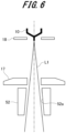
- FIG. 6 is an explanatory diagram illustrating a periphery of an anode in the three-dimensional PBF-AM apparatus 1D according to the fifth embodiment example.
- the three-dimensional PBF-AM apparatus 1D according to the fifth embodiment example is different from the three-dimensional PBF-AM apparatus 1 according to the first embodiment example in that a third vacuum pump 57 and a vacuum conductance component 52. Therefore, parts in common with those of the three-dimensional PBF-AM apparatus 1 according to the first embodiment example, and redundant description will be omitted.
- the three-dimensional PBF-AM apparatus 1D includes the third vacuum pump 57 and the vacuum conductance component 52.
- an evacuation passage 58 is formed closer to a side of an electron gun chamber 2 than a differential evacuation AP14 in a beam path 8.
- the evacuation passage 58 is connected to the third vacuum pump 57.
- the third vacuum pump 57 evacuates air in a space on the side of the electron gun chamber 2 divided by the differential evacuation AP14 in the beam path 8.
- the vacuum conductance component 52 is disposed in the vicinity of an anode 17 in the beam path 8. Specifically, the vacuum conductance component 52 is disposed on a downstream side of an electron beam L1 in an opening of the anode 17, that is, at a connection point between the electron gun chamber 2 and the beam path 8.
- the vacuum conductance component 52 includes a cylindrical hole 52a through which the electron beam L1 can pass.
- An opening diameter of the cylindrical hole 52a is set to be smaller than an opening diameter of the beam path 8.
- the cylindrical hole 52a is formed along an optical axis L2 of the electron beam L1.
- the cylindrical hole 52a is formed in a tapered shape in accordance with the spread of the electron beam L1. Consequently, it is possible to prevent the electron beam L1 from hitting the vacuum conductance component 52 while securing the axial length of the cylindrical hole 52a. Then, the vacuum conductance component 52 makes it difficult for gas to flow from the beam path 8 into an internal space of the electron gun chamber 2.
- the vacuum conductance component 52 is provided, whereby the internal space of the beam path 8 is divided into a space closer to a side of a build chamber 3 than the differential evacuation AP14 and a space surrounded by the differential evacuation AP14 and the vacuum conductance component 52. Therefore, the three-dimensional PBF-AM apparatus 1D according to the fifth embodiment example includes a first space formed by the electron gun chamber 2, a second space formed by the build chamber 3 and the differential evacuation AP14, and an intermediate space formed by the differential evacuation AP14 and the vacuum conductance component 52 in the beam path 8.
- first space, the second space, and the intermediate space are evacuated by a first vacuum pump 5, a second vacuum pump 6, and the third vacuum pump 57, respectively.
- the first vacuum pump 5, the second vacuum pump 6, and the third vacuum pump 57 are separate vacuum pumps.
- the intermediate space is formed by the vacuum conductance component 52 and the differential evacuation AP14, whereby it is possible to further prevent gas from flowing from the second space on the side of the build chamber 3 into the first space on the side of the electron gun chamber 2.
- a degree of vacuum in the electron gun chamber 2 can be further increased.
- the present invention is not limited to this.
- the anode 17 and the vacuum conductance component 52 may be integrally formed, that is, a cylindrical hole 52a as illustrated in FIG. 6 may be formed integrally with an anode 17.
- configurations of the three-dimensional PBF-AM apparatuses 1B, 1C, and 1D according to the second to fourth embodiment examples may be applied to the three-dimensional PBF-AM apparatus 1D according to the fifth embodiment example.
- an example in which a three-pole structure of the electron source (cathode) 10, the Wehnelt 18, and the anode 17 is applied as the electron gun has been described, but the present invention is not limited to this.
- An electron gun may have a two-pole structure without the Wehnelt 18, or the number of electrodes may be further increased.
- parallel and orthogonal terms such as “parallel” and “orthogonal” have been used. However, these terms “parallel” and “orthogonal” do not mean only strict “parallel” and strict “orthogonal”, respectively.
- the term “parallel” may include meanings of being “parallel” and also being “substantially parallel” in a range in which the function can be exhibited.
- the term “orthogonal” may include meanings of being “orthogonal” and also being “substantially orthogonal” in a range in which the function can be exhibited.
Landscapes
- Engineering & Computer Science (AREA)
- Chemical & Material Sciences (AREA)
- Materials Engineering (AREA)
- Manufacturing & Machinery (AREA)
- Physics & Mathematics (AREA)
- Optics & Photonics (AREA)
- Health & Medical Sciences (AREA)
- Toxicology (AREA)
- Plasma & Fusion (AREA)
- Mechanical Engineering (AREA)
- General Health & Medical Sciences (AREA)
- Analytical Chemistry (AREA)
- Automation & Control Theory (AREA)
- Environmental & Geological Engineering (AREA)
- Powder Metallurgy (AREA)
- Electron Sources, Ion Sources (AREA)
Abstract
Description
- The present invention relates to a three-dimensional powder bed fusion additive manufacturing (PBF-AM) apparatus that builds an object by building up layers, in each of which a powder material is thinly spread, on a layer-by-layer basis.
- In recent years, a three-dimensional PBF-AM technique that builds an object by building up layers, in each of which a powder material is thinly spread, on a layer-by-layer basis is in the limelight, and many types of three-dimensional PBF-AM techniques have been developed owing to differences in materials of powder materials and manufacturing methods.
- In a method of building an object with a conventional three-dimensional PBF-AM apparatus, for example, a powder material is spread, on a layer-by-layer basis, on a base plate installed on an upper surface of a stage. Next, with respect to the powder material spread on the base plate, only a two-dimensional structure portion corresponding to one cross-section of a built object is melted by a heating mechanism including an electron beam or a laser. Then, such layers of the powder material are built up on a layer-by-layer basis in a height direction (Z direction) to form a built object (see, for example, Patent Literature 1).
- In addition, since a high voltage such as an acceleration voltage is applied to an electron gun that is a source of the electron beam, an electron gun chamber accommodating the electron gun is required to have a high degree of vacuum in order to reduce electric discharge. In addition, the inside of the electron gun chamber is evacuated by a vacuum pump in order to protect an electron source from residual gas that causes a chemical reaction such as oxidation.
- However, it is necessary to frequently open a build chamber in which a build unit that builds a built object is accommodated to the atmosphere to replace the built object and the build unit. Furthermore, when the powder material is melted by the electron beam, steam is generated, and a degree of vacuum in the build chamber is lower than a degree of vacuum in the electron gun chamber.
- In addition, the electron gun chamber and the build chamber physically communicate with each other by a beam path through which the electron beam passes. Then, not only the electron beam but also gas in the build chamber passes through the beam path. Therefore, the gas passes through the beam path from the build chamber having a low degree of vacuum to the electron gun chamber having a high degree of vacuum.
- Therefore, in order to increase the degree of vacuum in the electron gun chamber, for example, there is used a differential evacuation system in which different vacuum pumps are connected to the electron gun chamber and the build chamber, and gas in the electron gun chamber and the build chamber are evacuated by the different vacuum pumps.
-
FIG. 7 is an explanatory diagram illustrating a relationship between a degree of vacuum in anelectron gun chamber 102 and a degree of vacuum in abuild chamber 103.
As illustrated inFIG. 7 , afirst vacuum pump 105 is connected to theelectron gun chamber 102, and asecond vacuum pump 106 is connected to thebuild chamber 103. In addition, theelectron gun chamber 102 and thebuild chamber 103 physically communicate with each other through a beam path through which an electron beam passes. Then, gas in thebuild chamber 103 flows into theelectron gun chamber 102 through the beam path. - Here, a pressure in the
electron gun chamber 102 is a first pressure P1 (Pa), and a pressure in thebuild chamber 103 is a second pressure P2 (Pa). Then, theelectron gun chamber 102 has a higher degree of vacuum than the build chamber 103 (P1 < P2). At this time, a gas flow rate Q (Pa-L/s) of the gas flowing from thebuild chamber 103 into theelectron gun chamber 102 is obtained by the following Formula 1. Note that C is a characteristic value called conductance indicating ease of gas flow.
- Then, when the evacuation performance of the
first vacuum pump 105 connected to theelectron gun chamber 102 exceeds the gas flow rate Q, theelectron gun chamber 102 can be maintained at a high degree of vacuum. In addition, the gas flow rate Q can be reduced by reducing conductance C to be small as illustrated in Formula 1. - Patent Literature 1:
JP 2015-168228 A - However, since the electron beam emitted from the electron gun continues to spread until being focused by a lens, it is difficult to reduce an opening diameter of the beam path communicating between the electron gun chamber and the build chamber. As the opening diameter of the beam path increases, conductance C increases, and a gas flow rate Q of the gas flowing from the build chamber into the electron gun chamber also increases. As a result, not only the degree of vacuum in the electron gun chamber decreases, but also a vacuum pump having more excellent evacuation performance is required.
- An object of the present invention is to provide a three-dimensional PBF-AM apparatus capable of increasing a degree of vacuum of an electron gun chamber in consideration of the above problems.
- In order to solve the above problems and achieve the object of the present invention, a three-dimensional PBF-AM apparatus of the present invention includes an electron gun chamber accommodating an electron gun, a build chamber accommodating a build unit to be irradiated with an electron beam emitted from the electron gun, a first vacuum pump, a second vacuum pump, and a beam path. The first vacuum pump evacuates gas in the electron gun chamber. The second vacuum pump evacuates gas in the build chamber. The electron beam path communicates the electron gun chamber and the build chamber, and the electron beam passes through the electron beam path.
In addition, the three-dimensional PBF-AM apparatus includes a differential evacuation aperture, a focusing lens, and an axis adjustment mechanism. The differential evacuation aperture is provided in the beam path to divide an internal space of the beam path into two, and has a restriction hole through which the electron beam can pass. The focusing lens focuses the electron beam emitted from the electron gun using the restriction hole of the differential evacuation aperture. The axis adjustment mechanism adjusts a trajectory of the electron beam or positions of the focusing lens and the differential evacuation aperture such that an optical axis of the electron beam passes through both the center of the restriction hole of the differential evacuation aperture and the center of the focusing lens. - According to the three-dimensional PBF-AM apparatus of the present invention, the degree of vacuum of the electron gun chamber can be increased.
-
-
FIG. 1 is a cross-sectional diagram schematically illustrating a three-dimensional PBF-AM apparatus according to a first embodiment example of the present invention; -
FIG. 2 is a cross-sectional diagram schematically illustrating a three-dimensional PBF-AM apparatus according to a second embodiment example of the present invention; -
FIG. 3 is a cross-sectional diagram schematically illustrating a three-dimensional PBF-AM apparatus according to a third embodiment example of the present invention; -
FIG. 4 is a cross-sectional diagram schematically illustrating a three-dimensional PBF-AM apparatus according to a fourth embodiment example of the present invention; -
FIG. 5 is a cross-sectional diagram schematically illustrating a three-dimensional PBF-AM apparatus according to a fifth embodiment example of the present invention; -
FIG. 6 is an explanatory diagram illustrating a periphery of an anode in the three-dimensional PBF-AM apparatus according to the fifth embodiment example; and -
FIG. 7 is an explanatory diagram illustrating a relationship between a degree of vacuum in an electron gun chamber and a degree of vacuum in a build chamber. - First, with reference to
FIGS. 1 to 7 , three-dimensional PBF-AM apparatuses according to embodiment examples of the present invention will be described. Note that the same reference signs are given to common members in the drawings. - First, with reference to
FIG. 1 , a three-dimensional PBF-AM apparatus 1 according to a first embodiment example (hereinafter, referred to as "the present example") of the present invention will be described. -
FIG. 1 is a cross-sectional diagram schematically illustrating the three-dimensional PBF-AM apparatus 1 of the present example. - The three-dimensional PBF-AM apparatus 1 illustrated in
FIG. 1 is an apparatus that irradiates a powder material made of a metal powder of, for example, titanium, aluminum, iron, or the like with an electron beam L1 to melt the powder material, and builds up layers, in each of which the powder material is solidified, to build a three-dimensional object. - As illustrated in
FIG. 1 , the three-dimensional PBF-AM apparatus 1 includes anelectron gun chamber 2, abuild chamber 3, an electronoptical chamber 4, afirst vacuum pump 5, asecond vacuum pump 6, abuild unit 7, abeam path 8, and anelectron source 10. Theelectron gun chamber 2 and thebuild chamber 3 are formed in a hollow shape. Thefirst vacuum pump 5 is connected to theelectron gun chamber 2, and thesecond vacuum pump 6 is connected to thebuild chamber 3. Air in theelectron gun chamber 2 is evacuated by thefirst vacuum pump 5, and air in thebuild chamber 3 is evacuated by thesecond vacuum pump 6. - The
build unit 7 is disposed inside thebuild chamber 3. Layers of the powder material are built up in thebuild unit 7. Then, the built up layers of the powder material is melted by being irradiated with an electron beam L1 from theelectron source 10 to be described later. - The electron
optical chamber 4 is connected to an upper portion of thebuild chamber 3. The electronoptical chamber 4 accommodates thetubular beam path 8. A lower portion of thebeam path 8 communicates with thebuild chamber 3, and an upper portion of thebeam path 8 communicates with theelectron gun chamber 2. - In the Inside of the
electron gun chamber 2, theelectron source 10 indicating a cathode, aWehnelt 18, and ananode 17 are accommodated. Then, theelectron source 10, theWehnelt 18, and theanode 17 constitute an electron gun. Theanode 17 is provided in an opening communicating with thebeam path 8 in theelectron gun chamber 2. The electron beam L1 emitted from theelectron source 10 passes through theWehnelt 18 and is emitted into thebeam path 8 through theanode 17. - In addition, the output of the electron beam L1 emitted from the
electron source 10, theWehnelt 18, and theanode 17 is configured to be variable by a control device (not illustrated) according to a build process. - The electron
optical chamber 4 includes anobjective lens 11, a focusinglens 12, anaxis adjustment mechanism 13, and a differential evacuation aperture (hereinafter, referred to as "differential evacuation AP") 14. In the present example, theobjective lens 11, the focusinglens 12, and a coil that generates a magnetic field are included. - The differential evacuation AP14 is disposed between the
objective lens 11 and the focusinglens 12 to be described later in thebeam path 8. Arestriction hole 14a through which the electron beam L1 can pass is formed in the differential evacuation AP14. The differential evacuation AP14 divides an internal space of thebeam path 8 into two, that is, a space on a side of theelectron gun chamber 2 and a space on a side of thebuild chamber 3. - The differential evacuation AP14 is provided, whereby gas hardly flows from the space on the side of the
build chamber 3 to the space on the side of theelectron gun chamber 2. In other words, conductance C can be reduced by the differential evacuation AP14, and the gas can be prevented from passing through thebeam path 8 from thebuild chamber 3 and flowing into theelectron gun chamber 2. This, as a result, makes it possible to set a degree of vacuum of theelectron gun chamber 2 to a desired degree of vacuum without using a vacuum pump having high evacuation performance as thefirst vacuum pump 5. - In addition, since the degree of vacuum of the
electron gun chamber 2 can be set to a high degree of vacuum, theelectron source 10 disposed in theelectron gun chamber 2 can be prevented from being deteriorated due to gas, and the product life of theelectron source 10 can be increased. - The
objective lens 11 is disposed closer to the side of thebuild chamber 3 than the differential evacuation AP14 in the electronoptical chamber 4. Then, theobjective lens 11 focuses the electron beam L1 that has passed through theaxis adjustment mechanism 13, the focusinglens 12, and the differential evacuation AP14 so that the electron beam L1 has a predetermined beam diameter on a build surface of thebuild unit 7. - The focusing
lens 12 is disposed closer to the side of theelectron gun chamber 2 than the differential evacuation AP14 in the electronoptical chamber 4, that is, on an upstream (electron source 10) side of the electron beam L1. The focusinglens 12 focuses the electron beam L1 that has passed through theanode 17 so that the electron beam L1 passes through therestriction hole 14a of the differential evacuation AP14. Specifically, the focusinglens 12 focuses the electron beam L1 so that a beam diameter of the electron beam L1 is smaller than an opening diameter of therestriction hole 14a. In addition, a focal position of the focusinglens 12 is adjusted to coincide with the center of therestriction hole 14a of the differential evacuation AP14. - By narrowing the beam diameter of the electron beam L1 by the focusing
lens 12, the opening diameter of therestriction hole 14a of the differential evacuation AP14 can be further reduced. As a result, it is possible to further reduce the conductance C can be further reduced by the differential evacuation AP14, and it is possible to enhance the effect of preventing the inflow of the gas from the space on the side of thebuild chamber 3 to the space on the side of theelectron gun chamber 2. - In addition, the focusing
lens 12 makes the beam diameter of the electron beam L1 smaller than the opening diameter of therestriction hole 14a of the differential evacuation AP14, whereby it is possible to prevent the electron beam L1 from being emitted to the differential evacuation AP14. As a result, it is possible to prevent the electron beam L1 from hitting the differential evacuation AP14 and damaging the differential evacuation AP14. - The
axis adjustment mechanism 13 is disposed between the focusinglens 12 and theelectron gun chamber 2, that is, on the upstream (electron source 10) side of the electron beam L1 from the focusinglens 12. Theaxis adjustment mechanism 13 includes afirst adjustment unit 13a and asecond adjustment unit 13b. Thefirst adjustment unit 13a and thesecond adjustment unit 13b are disposed along an optical axis L2 of the electron beam L1. Thefirst adjustment unit 13a and thesecond adjustment unit 13b are electromagnetic deflectors that generate a magnetic field. In addition, as thefirst adjustment unit 13a and thesecond adjustment unit 13b, for example, saddle-type coils or other various electromagnetic deflectors are applied. - The
first adjustment unit 13a and thesecond adjustment unit 13b adjust a trajectory of the electron beam L1 so that the trajectory of the electron beam L1 coincides with a magnetic field center of the focusinglens 12 and the center of the opening of therestriction hole 14a of the differential evacuation AP14 in a direction in which the optical axis L2 of the electron beam L1 that has passed through theanode 17 is orthogonal to the optical axis L2 (hereinafter, referred to as second direction). In other words, theaxis adjustment mechanism 13 causes the entire electron beam L1 emitted from theelectron source 10 to passes through therestriction hole 14a of the differential evacuation AP14. Consequently, the trajectory of the electron beam L1 can be prevented from deviating from therestriction hole 14a in the second direction, and the electron beam L1 can reliably pass through therestriction hole 14a. As a result, it is possible to reliably prevent the differential evacuation AP14 from being damaged by irradiating the differential evacuation AP14 with the electron beam L1, and it is possible to further enhance the safety of the three-dimensional PBF-AM apparatus 1. - In addition, two adjustment units that are the
first adjustment unit 13a and thesecond adjustment unit 13b are provided as theaxis adjustment mechanism 13, whereby the optical axis L2 can be adjusted to pass through two centers that are the center of the focusinglens 12 and the center of therestriction hole 14a. - As described above, the output of the electron beam L1 emitted from the
electron source 10 changes according to a voltage applied to theWehnelt 18. When the output of the electron beam L1 changes, the spread of the electron beam L1 also changes. Therefore, the control device can control the focusinglens 12 and theaxis adjustment mechanism 13 according to the output of the electron beam L1. Consequently, even in a case where the output of the electron beam L1 changes, the optical axis L2 of the electron beam L1 can be caused to pass through the magnetic field center of the focusinglens 12 and the center of the opening of therestriction hole 14a of the differential evacuation AP14. Furthermore, a focal position of the focusinglens 12 can be aligned with a position of the center of the opening of therestriction hole 14a of the differential evacuation AP14. - Next, with reference to
FIG. 2 , a three-dimensional PBF-AM apparatus 1A according to a second embodiment example will be described. -
FIG. 2 is a schematic configuration diagram illustrating the three-dimensional PBF-AM apparatus 1A according to a second embodiment example. - The three-dimensional PBF-
AM apparatus 1A according to the second embodiment example is different from the three-dimensional PBF-AM apparatus 1 according to the first embodiment example in configurations of a focusing lens and an axis adjustment mechanism. Therefore, parts in common with those of the three-dimensional PBF-AM apparatus 1 according to the first embodiment example, and redundant description will be omitted. - As illustrated in
FIG. 2 , the three-dimensional PBF-AM apparatus 1A includes a focusinglens 22 and anaxis adjustment mechanism 23. The focusinglens 22 according to the second embodiment example is an electrostatic lens, and theaxis adjustment mechanism 23 is an electrostatic deflector. In other words, the focusinglens 22 and theaxis adjustment mechanism 23 include a plurality of electrodes facing each other to which a voltage is applied. Then, the voltage is applied to the electrodes to generate an electric field in abeam path 8, whereby the focusinglens 22 and theaxis adjustment mechanism 23 controls the focusing and trajectory of an electron beam L1. - Other configurations are similar to those of the three-dimensional PBF-AM apparatus 1 according to the first embodiment example, and thus the description thereof will be omitted. With such a three-dimensional PBF-
AM apparatus 1A including the focusinglens 22 and theaxis adjustment mechanism 23, it is also possible to obtain actions and effects similar to those of the three-dimensional PBF-AM apparatus 1 according to the first embodiment example described above. - Next, with reference to
FIG. 3 , a three-dimensional PBF-AM apparatus 1B according to a third embodiment example will be described. -
FIG. 3 is a schematic configuration diagram illustrating the three-dimensional PBF-AM apparatus 1B according to the third embodiment example. - The three-dimensional PBF-
AM apparatus 1B according to the third embodiment example is different from the three-dimensional PBF-AM apparatus 1 according to the first embodiment example in a configuration of an axis adjustment mechanism. Therefore, parts in common with those of the three-dimensional PBF-AM apparatus 1 according to the first embodiment example, and redundant description will be omitted. - As illustrated in
FIG. 3 , the three-dimensional PBF-AM apparatus 1B includes a firstaxis adjustment mechanism 32 and a secondaxis adjustment mechanism 33. The firstaxis adjustment mechanism 32 is connected to a focusinglens 12, and the secondaxis adjustment mechanism 33 is connected to a differential evacuation AP14. In addition, the firstaxis adjustment mechanism 32 supports the focusinglens 12 in a manner such that the focusinglens 12 is movable along a second direction that is a direction orthogonal to an optical axis L2. - Then, the first
axis adjustment mechanism 32 adjusts a position of the focusinglens 12 so that the optical axis L2 of the electron beam L1 passes through the center of the focusinglens 12. - The second
axis adjustment mechanism 33 supports the differential evacuation AP14 in a manner such that the differential evacuation AP14 is movable along the second direction. Then, the secondaxis adjustment mechanism 33 adjusts a position of the differential evacuation AP14 so that the optical axis L2 of the electron beam L1 passes through the center of arestriction hole 14a of the differential evacuation AP14. - Other configurations are similar to those of the three-dimensional PBF-AM apparatus 1 according to the first embodiment example, and thus the description thereof will be omitted. With such a three-dimensional PBF-
AM apparatus 1B including the firstaxis adjustment mechanism 32 and the secondaxis adjustment mechanism 33, it is also possible to obtain actions and effects similar to those of the three-dimensional PBF-AM apparatus 1 according to the first embodiment example described above. - Next, with reference to
FIG. 4 , a three-dimensional PBF-AM apparatus 1C according to a fourth embodiment example will be described. -
FIG. 4 is a schematic configuration diagram illustrating the three-dimensional PBF-AM apparatus 1C according to the fourth embodiment example. - The three-dimensional PBF-
AM apparatus 1C according to the fourth embodiment example is different from the three-dimensional PBF-AM apparatus 1 according to the first embodiment example in that abeam detection unit 45 is provided. Therefore, parts in common with those of the three-dimensional PBF-AM apparatus 1 according to the first embodiment example, and redundant description will be omitted. - As illustrated in
FIG. 4 , the three-dimensional PBF-AM apparatus 1C includes thebeam detection unit 45. Thebeam detection unit 45 detects that a differential evacuation AP14 has been irradiated with an electron beam L1. As thebeam detection unit 45, for example, configurations of other various beam detection such as current detection, temperature detection, and X-ray detection are applied. - Then, when it is detected that the differential evacuation AP14 has been irradiated with the electron beam L1 from a detection signal of the
beam detection unit 45, a control device (not illustrated) of the three-dimensional PBF-AM apparatus 1C stops emission of the electron beam L1 from anelectron source 10. Consequently, it is possible to prevent the differential evacuation AP14 from being irradiated with the electron beam L1 and the differential evacuation AP14 from being damaged. - In addition, the control device may control an
axis adjustment mechanism 13 on the basis of the detection signal of thebeam detection unit 45. In other words, the control device controls theaxis adjustment mechanism 13 so that the electron beam L1 does not hit the differential evacuation AP14 on the basis of the detection signal of thebeam detection unit 45. Consequently, the work of adjusting the electron beam L1 by theaxis adjustment mechanism 13 can be easily performed. - In addition, during the work of adjusting the
axis adjustment mechanism 13, the output of the electron beam L1 emitted from theelectron source 10 is weakened. As a result, it is possible to prevent the differential evacuation AP14 from being damaged during the work of adjusting. - Other configurations are similar to those of the three-dimensional PBF-AM apparatus 1 according to the first embodiment example, and thus the description thereof will be omitted. With such a three-dimensional PBF-
AM apparatus 1C including thebeam detection unit 45, it is also possible to obtain actions and effects similar to those of the three-dimensional PBF-AM apparatus 1 according to the first embodiment example described above. - Next, with reference to
FIGS. 5 and6 , a three-dimensional PBF-AM apparatus 1D according to a fifth embodiment example will be described. -
FIG. 5 is a schematic configuration diagram illustrating the three-dimensional PBF-AM apparatus 1D according to the fifth embodiment example.FIG. 6 is an explanatory diagram illustrating a periphery of an anode in the three-dimensional PBF-AM apparatus 1D according to the fifth embodiment example. - The three-dimensional PBF-
AM apparatus 1D according to the fifth embodiment example is different from the three-dimensional PBF-AM apparatus 1 according to the first embodiment example in that athird vacuum pump 57 and avacuum conductance component 52. Therefore, parts in common with those of the three-dimensional PBF-AM apparatus 1 according to the first embodiment example, and redundant description will be omitted. - As illustrated in
FIG. 5 , the three-dimensional PBF-AM apparatus 1D includes thethird vacuum pump 57 and thevacuum conductance component 52. In addition, anevacuation passage 58 is formed closer to a side of anelectron gun chamber 2 than a differential evacuation AP14 in abeam path 8. Theevacuation passage 58 is connected to thethird vacuum pump 57. Thethird vacuum pump 57 evacuates air in a space on the side of theelectron gun chamber 2 divided by the differential evacuation AP14 in thebeam path 8. - As illustrated in
FIGS. 5 and6 , thevacuum conductance component 52 is disposed in the vicinity of ananode 17 in thebeam path 8. Specifically, thevacuum conductance component 52 is disposed on a downstream side of an electron beam L1 in an opening of theanode 17, that is, at a connection point between theelectron gun chamber 2 and thebeam path 8. - The
vacuum conductance component 52 includes acylindrical hole 52a through which the electron beam L1 can pass. An opening diameter of thecylindrical hole 52a is set to be smaller than an opening diameter of thebeam path 8. Thecylindrical hole 52a is formed along an optical axis L2 of the electron beam L1. In addition, thecylindrical hole 52a is formed in a tapered shape in accordance with the spread of the electron beam L1. Consequently, it is possible to prevent the electron beam L1 from hitting thevacuum conductance component 52 while securing the axial length of thecylindrical hole 52a. Then, thevacuum conductance component 52 makes it difficult for gas to flow from thebeam path 8 into an internal space of theelectron gun chamber 2. - The
vacuum conductance component 52 is provided, whereby the internal space of thebeam path 8 is divided into a space closer to a side of abuild chamber 3 than the differential evacuation AP14 and a space surrounded by the differential evacuation AP14 and thevacuum conductance component 52. Therefore, the three-dimensional PBF-AM apparatus 1D according to the fifth embodiment example includes a first space formed by theelectron gun chamber 2, a second space formed by thebuild chamber 3 and the differential evacuation AP14, and an intermediate space formed by the differential evacuation AP14 and thevacuum conductance component 52 in thebeam path 8. - Furthermore, the first space, the second space, and the intermediate space are evacuated by a
first vacuum pump 5, asecond vacuum pump 6, and thethird vacuum pump 57, respectively. Thefirst vacuum pump 5, thesecond vacuum pump 6, and thethird vacuum pump 57 are separate vacuum pumps. In this manner, the intermediate space is formed by thevacuum conductance component 52 and the differential evacuation AP14, whereby it is possible to further prevent gas from flowing from the second space on the side of thebuild chamber 3 into the first space on the side of theelectron gun chamber 2. As a result, a degree of vacuum in theelectron gun chamber 2 can be further increased. - Note that although an example in which the
vacuum conductance component 52 and theanode 17 are separate members has been described, the present invention is not limited to this. For example, theanode 17 and thevacuum conductance component 52 may be integrally formed, that is, acylindrical hole 52a as illustrated inFIG. 6 may be formed integrally with ananode 17. - Other configurations are similar to those of the three-dimensional PBF-AM apparatus 1 according to the first embodiment example, and thus the description thereof will be omitted. With such a three-dimensional PBF-
AM apparatus 1D including thethird vacuum pump 57 and thevacuum conductance component 52, it is also possible to obtain actions and effects similar to those of the three-dimensional PBF-AM apparatus 1 according to the first embodiment example described above. - In addition, the configurations of the three-dimensional PBF-
AM apparatuses AM apparatus 1D according to the fifth embodiment example. - Note that the present invention is not limited to the embodiment examples described above and illustrated in the drawings, and various modifications can be made without departing from the gist of the invention described in the claims.
- In the embodiment examples described above, an example in which a three-pole structure of the electron source (cathode) 10, the
Wehnelt 18, and theanode 17 is applied as the electron gun has been described, but the present invention is not limited to this. An electron gun may have a two-pole structure without theWehnelt 18, or the number of electrodes may be further increased. - For example, in the embodiment examples described above, an example in which a metal powder of titanium, aluminum, iron, or the like is applied as the powder material has been described, but the present invention is not limited to this, and a resin or the like may be used as the powder material.
- In the present specification, terms such as "parallel" and "orthogonal" have been used. However, these terms "parallel" and "orthogonal" do not mean only strict "parallel" and strict "orthogonal", respectively. The term "parallel" may include meanings of being "parallel" and also being "substantially parallel" in a range in which the function can be exhibited. The term "orthogonal" may include meanings of being "orthogonal" and also being "substantially orthogonal" in a range in which the function can be exhibited.
-
- 1, 1A, 1B, 1C, 1D
- Three-dimensional powder bed fusion additive manufacturing (PBF-AM) apparatus
- 2
- Electron gun chamber
- 3
- Build chamber
- 4
- Electron optical chamber
- 5
- First vacuum pump
- 6
- Second vacuum pump
- 7
- Build unit
- 8
- Beam path
- 10
- Electron source
- 11
- Objective lens
- 12, 22
- Focusing lens
- 13, 23
- Axis adjustment mechanism
- 13a
- First adjustment unit
- 13b
- Second adjustment unit
- 14
- Differential evacuation aperture
- 14a
- Restriction hole
- 17
- Anode
- 18
- Wehnelt
- 32
- First axis adjustment mechanism
- 33
- Second axis adjustment mechanism
- 45
- Beam detection unit
- 52
- Vacuum conductance component
- 52a
- Cylindrical hole
- 57
- Third vacuum pump
- 58
- Evacuation passage
- L1
- Electron beam
- L2
- Optical axis
Claims (8)
- A three-dimensional powder bed fusion additive manufacturing (PBF-AM) apparatus (1), comprising:an electron gun chamber (2) accommodating an electron gun;a build chamber (3) accommodating a build unit (7) to be irradiated with an electron beam (L1) emitted from the electron gun;a first vacuum pump (5) configured to evacuates gas in the electron gun chamber (2);a second vacuum pump (6) configured to evacuate gas in the build chamber (3);a beam path (8) configured to communicate the electron gun chamber (2) and the build chamber (3) and through which the electron beam (L1) passes;a differential evacuation aperture (14) provided in the beam path (8) to divide an internal space of the beam path (8) into two, the differential evacuation aperture (14) having a restriction hole (14a) through which the electron beam (L1) can pass;a focusing lens (12) configured to focus the electron beam (L1) emitted from the electron gun using the restriction hole (14a) of the differential evacuation aperture (14); andan axis adjustment mechanism (13) configured to adjust a trajectory of the electron beam (L1) or positions of the focusing lens (12) and the differential evacuation aperture (14) so that an optical axis (L2) of the electron beam (L1) passes through both a center of the restriction hole (14a) of the differential evacuation aperture (14) and a center of the focusing lens (12).
- The three-dimensional PBF-AM apparatus (1) according to claim 1, whereinthe axis adjustment mechanism (13) is configured to adjust the trajectory of the electron beam (L1), andhas a first adjustment unit (13a) and a second adjustment unit (13b) disposed along the optical axis (L2) of the electron beam (L1).
- The three-dimensional PBF-AM apparatus (1) according to claim 2, wherein
the axis adjustment mechanism (13) is an electromagnetic deflector. - The three-dimensional PBF-AM apparatus (1) according to claim 2, wherein
the focusing lens (12) and the axis adjustment mechanism (13) are electrostatic deflectors. - The three-dimensional PBF-AM apparatus (1) according to claim 1, wherein the axis adjustment mechanism (13) includes:a first axis adjustment mechanism (32) configured to move the focusing lens (12) in a direction orthogonal to the optical axis (L2); anda second axis adjustment mechanism (33) configured to move the differential evacuation aperture (14) in the direction orthogonal to the optical axis (L2).
- The three-dimensional PBF-AM apparatus (1) according to any preceding claim, further comprising
a beam detection unit (45) configured to detect that the differential evacuation aperture (14) has been irradiated with the electron beam (L1). - The three-dimensional PBF-AM apparatus (1) according to any preceding claim, further comprising:a vacuum conductance component (52) that is disposed at a connection point between the electron gun chamber (2) and the beam path (8) and through which the electron beam (L1) can pass; anda third vacuum pump (57) configured to evacuate gas in a space divided by the differential evacuation aperture (14) in the beam path (8), the space being formed of the differential evacuation aperture (14) and the vacuum conductance component (52).
- The three-dimensional PBF-AM apparatus (1) according to claim 7, wherein
the vacuum conductance component (52) is formed integrally with an anode (17) fixing the electron gun.
Applications Claiming Priority (1)
| Application Number | Priority Date | Filing Date | Title |
|---|---|---|---|
| JP2022104255A JP7514885B2 (en) | 2022-06-29 | 2022-06-29 | 3D additive manufacturing equipment |
Publications (1)
| Publication Number | Publication Date |
|---|---|
| EP4299217A1 true EP4299217A1 (en) | 2024-01-03 |
Family
ID=86693091
Family Applications (1)
| Application Number | Title | Priority Date | Filing Date |
|---|---|---|---|
| EP23177180.9A Pending EP4299217A1 (en) | 2022-06-29 | 2023-06-05 | Three-dimensional powder bed fusion additive manufacturing apparatus |
Country Status (3)
| Country | Link |
|---|---|
| US (1) | US20240001449A1 (en) |
| EP (1) | EP4299217A1 (en) |
| JP (1) | JP7514885B2 (en) |
Families Citing this family (1)
| Publication number | Priority date | Publication date | Assignee | Title |
|---|---|---|---|---|
| DE102024207110A1 (en) * | 2024-07-29 | 2026-01-29 | Pro-Beam Gmbh & Co. Kgaa | Beam generation assembly for a device for producing a component layer from at least one powder layer using an electron beam, and use of an aperture unit with an aperture. |
Citations (4)
| Publication number | Priority date | Publication date | Assignee | Title |
|---|---|---|---|---|
| US20130300286A1 (en) * | 2012-05-09 | 2013-11-14 | Arcam Ab | Method and apparatus for generating electron beams |
| JP2015168228A (en) | 2014-03-10 | 2015-09-28 | 日本電子株式会社 | Apparatus and method for molding three-dimensional laminate |
| US20190193192A1 (en) * | 2017-12-22 | 2019-06-27 | Arcam Ab | Enhanced electron beam generation |
| US20190337085A1 (en) * | 2017-01-12 | 2019-11-07 | Advantest Corporation | Electron beam column for three-dimensional printing device, three-dimensional printing device, and three-dimensional printing method |
Family Cites Families (3)
| Publication number | Priority date | Publication date | Assignee | Title |
|---|---|---|---|---|
| JP2964873B2 (en) * | 1994-06-14 | 1999-10-18 | 株式会社島津製作所 | Electron beam alignment system |
| JP2013201143A (en) | 2013-06-28 | 2013-10-03 | Hitachi High-Technologies Corp | Charged-particle gun and charged-particle beam device |
| JP7222257B2 (en) | 2019-02-04 | 2023-02-15 | 株式会社Ihi | 3D printer |
-
2022
- 2022-06-29 JP JP2022104255A patent/JP7514885B2/en active Active
-
2023
- 2023-06-05 EP EP23177180.9A patent/EP4299217A1/en active Pending
- 2023-06-28 US US18/215,239 patent/US20240001449A1/en active Pending
Patent Citations (4)
| Publication number | Priority date | Publication date | Assignee | Title |
|---|---|---|---|---|
| US20130300286A1 (en) * | 2012-05-09 | 2013-11-14 | Arcam Ab | Method and apparatus for generating electron beams |
| JP2015168228A (en) | 2014-03-10 | 2015-09-28 | 日本電子株式会社 | Apparatus and method for molding three-dimensional laminate |
| US20190337085A1 (en) * | 2017-01-12 | 2019-11-07 | Advantest Corporation | Electron beam column for three-dimensional printing device, three-dimensional printing device, and three-dimensional printing method |
| US20190193192A1 (en) * | 2017-12-22 | 2019-06-27 | Arcam Ab | Enhanced electron beam generation |
Also Published As
| Publication number | Publication date |
|---|---|
| US20240001449A1 (en) | 2024-01-04 |
| JP2024004588A (en) | 2024-01-17 |
| JP7514885B2 (en) | 2024-07-11 |
Similar Documents
| Publication | Publication Date | Title |
|---|---|---|
| EP3867941B1 (en) | Field curvature corrector, charged particle beam device with this corrector, and methods of operating the charged particle beam device | |
| JP5970498B2 (en) | Dual beam system and control method thereof | |
| JP6554288B2 (en) | Charged particle beam equipment | |
| US7067820B2 (en) | Particle-optical apparatus with a permanent-magnetic lens and an electrostatic lens | |
| JP6037693B2 (en) | Charged particle beam equipment | |
| EP1830383A2 (en) | Particle-optical apparatus equipped with a gas ion source | |
| EP2561540A1 (en) | Improved ion source | |
| US20070069150A1 (en) | Charged particle beam energy width reduction system for charged particle beam system | |
| JP6389569B2 (en) | Monochromator and charged particle beam apparatus including the same | |
| JP2018174016A (en) | Charged particle beam equipment | |
| US20240001449A1 (en) | Three-Dimensional Powder Bed Fusion Additive Manufacturing Apparatus | |
| US7763862B2 (en) | Method of aberration correction and electron beam system | |
| JP4896877B2 (en) | Aberration corrector and method for operating the aberration corrector | |
| JP4357530B2 (en) | Two-stage charged particle beam energy width reduction system for charged particle beam system | |
| US20080185514A1 (en) | Achromatic mass separator | |
| JP2007073517A (en) | Device for generating x-ray or euv | |
| US8946650B2 (en) | Particle beam device and method for analyzing and/or treating an object | |
| JP5478683B2 (en) | Charged particle beam irradiation method and charged particle beam apparatus | |
| JP6261228B2 (en) | Focused ion beam apparatus, focused ion / electron beam processing observation apparatus, and sample processing method | |
| JPH06215712A (en) | Ion accelerator | |
| JP6420998B2 (en) | Electron gun equipment | |
| JP3844253B2 (en) | Particle beam chromatic aberration compensation column | |
| TWI807604B (en) | Charged particle beam apparatus, scanning electron microscope, and method of operating a charged particle beam apparatus | |
| EP4117013B1 (en) | Scanning electron microscope and objective lens | |
| JP7564194B2 (en) | X-ray generator |
Legal Events
| Date | Code | Title | Description |
|---|---|---|---|
| PUAI | Public reference made under article 153(3) epc to a published international application that has entered the european phase |
Free format text: ORIGINAL CODE: 0009012 |
|
| STAA | Information on the status of an ep patent application or granted ep patent |
Free format text: STATUS: THE APPLICATION HAS BEEN PUBLISHED |
|
| AK | Designated contracting states |
Kind code of ref document: A1 Designated state(s): AL AT BE BG CH CY CZ DE DK EE ES FI FR GB GR HR HU IE IS IT LI LT LU LV MC ME MK MT NL NO PL PT RO RS SE SI SK SM TR |
|
| STAA | Information on the status of an ep patent application or granted ep patent |
Free format text: STATUS: REQUEST FOR EXAMINATION WAS MADE |
|
| 17P | Request for examination filed |
Effective date: 20240226 |
|
| RBV | Designated contracting states (corrected) |
Designated state(s): AL AT BE BG CH CY CZ DE DK EE ES FI FR GB GR HR HU IE IS IT LI LT LU LV MC ME MK MT NL NO PL PT RO RS SE SI SK SM TR |