EP4299206A1 - Method for molding wire material, device for molding wire material - Google Patents
Method for molding wire material, device for molding wire material Download PDFInfo
- Publication number
- EP4299206A1 EP4299206A1 EP21928020.3A EP21928020A EP4299206A1 EP 4299206 A1 EP4299206 A1 EP 4299206A1 EP 21928020 A EP21928020 A EP 21928020A EP 4299206 A1 EP4299206 A1 EP 4299206A1
- Authority
- EP
- European Patent Office
- Prior art keywords
- wire material
- roller group
- amount
- push
- rollers
- Prior art date
- Legal status (The legal status is an assumption and is not a legal conclusion. Google has not performed a legal analysis and makes no representation as to the accuracy of the status listed.)
- Pending
Links
Images


Classifications
-
- B—PERFORMING OPERATIONS; TRANSPORTING
- B21—MECHANICAL METAL-WORKING WITHOUT ESSENTIALLY REMOVING MATERIAL; PUNCHING METAL
- B21B—ROLLING OF METAL
- B21B1/00—Metal-rolling methods or mills for making semi-finished products of solid or profiled cross-section; Sequence of operations in milling trains; Layout of rolling-mill plant, e.g. grouping of stands; Succession of passes or of sectional pass alternations
- B21B1/16—Metal-rolling methods or mills for making semi-finished products of solid or profiled cross-section; Sequence of operations in milling trains; Layout of rolling-mill plant, e.g. grouping of stands; Succession of passes or of sectional pass alternations for rolling wire rods, bars, merchant bars, rounds wire or material of like small cross-section
- B21B1/18—Metal-rolling methods or mills for making semi-finished products of solid or profiled cross-section; Sequence of operations in milling trains; Layout of rolling-mill plant, e.g. grouping of stands; Succession of passes or of sectional pass alternations for rolling wire rods, bars, merchant bars, rounds wire or material of like small cross-section in a continuous process
-
- B—PERFORMING OPERATIONS; TRANSPORTING
- B21—MECHANICAL METAL-WORKING WITHOUT ESSENTIALLY REMOVING MATERIAL; PUNCHING METAL
- B21F—WORKING OR PROCESSING OF METAL WIRE
- B21F1/00—Bending wire other than coiling; Straightening wire
- B21F1/02—Straightening
- B21F1/023—Straightening in a device rotating about the wire axis
-
- B—PERFORMING OPERATIONS; TRANSPORTING
- B21—MECHANICAL METAL-WORKING WITHOUT ESSENTIALLY REMOVING MATERIAL; PUNCHING METAL
- B21F—WORKING OR PROCESSING OF METAL WIRE
- B21F1/00—Bending wire other than coiling; Straightening wire
- B21F1/02—Straightening
Definitions
- the present invention relates to a method for shaping a wire material and a wire material shaping device.
- Patent Literature 1 discloses a rod wire material straightener that easily improves the straightness of a rod wire material and performs straightening by passing a metal rod wire material between a plurality of rolls.
- This straightener is characterized as follows.
- the straightener includes at least one unit group including two or more adjacent units, with the directions of straightening the rod wire material of the two or more units forming an angle of ⁇ 15 °.
- the unit includes two or more fixed rolls and movable rolls fewer than the fixed rolls by one.
- the fixed rolls and the movable rolls are arranged in a staggered manner so as to sandwich the running rod wire material with the fixed rolls arranged on one side of the running rod wire material and the movable rolls arranged on a side opposite to the fixed rolls with respect to the rod wire material.
- the push-in amounts of the movable roll closest to the inlet side and the movable roll closest to the outlet side of each unit can be set, and the push-in amounts of the adjacent units satisfy a predetermined relationship.
- a method for shaping a wire material according to the first aspect of the present invention is a method for shaping a wire material that moves from an upstream side to a downstream side which includes a first step of feeding the wire material while pressing the wire material by a first roller group including a plurality of rollers driven by a motor and a second step of feeding the wire material while pressing the wire material by a second roller group including a plurality of rotatably supported rollers.
- the first step is provided upstream side of the second step.
- a push-in amount that is the difference between the outer dimension of the wire material and the gap between rollers through which the wire material passes is larger in the first step than in the second step.
- a wire material shaping device includes a feeding unit that feeds a wire material, a first roller group including a plurality of rollers driven by a motor to press the wire material fed by the feeding unit and a second roller group that includes a plurality of rollers configured to further press the wire material pressed by the first roller group and is rotatably supported.
- a push-in amount that is the difference between the outer dimension of the wire material and the gap between rollers through which the wire material passes is larger in the first roller group than in the second roller group.
- the warpage of a wire material can be stably reduced.
- FIGS. 1 to 5 an embodiment of a wire material shaping device and a method for shaping a wire material according to the present invention will be described with reference to FIGS. 1 to 5 .
- FIG. 1 is a schematic view of a wire material processing system S including a shaping device 1.
- FIG. 1 illustrates the X-, Y-, and Z-axes orthogonal to each other for the sake of explanation.
- the X-axis is parallel to the left-right direction in FIG. 1 , and the right side in the drawing is a positive direction.
- the Z-axis is parallel to the up-down direction in FIG. 1 , and the upward direction in the drawing is a positive direction.
- the depth direction in FIG. 1 is a positive direction.
- the wire material processing system S includes a feeding device 700, the shaping device 1, a peeling device 800, and a cutting device 900.
- the wire material moves from left to right in the drawing and is processed in order.
- the left side in the drawing is also referred to as “upstream”
- the right side in the drawing is also referred to as "downstream”.
- a bobbin around which a wire material is wound is placed with its rotation axis parallel to the Y-axis.
- the feeding device 700 feeds the wire material wound around the bobbin to the shaping device 1.
- the wire material is warped in the Z direction in FIG. 1 by being wound around the bobbin.
- the shaping device 1 straightens the warpage of the wire material in the Z direction fed from the feeding device 700 and feeds the wire material to the peeling device 800.
- the "warpage” is also called “bend” or "warping tendency”.
- the peeling device 800 peels the insulating coating of the wire material by cutting, laser irradiation, or the like.
- the cutting device 900 cuts the wire material to a predetermined length.
- the configuration and operation of the shaping device 1 will be described in detail. Note that, referring to FIG. 1 , it is for convenience of drawing that the wire material is drawn in a straight line and is not an essential constituent element.
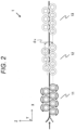
- FIG. 2 is a schematic configuration diagram of the shaping device 1.
- the shaping device 1 includes a first roller group 11, a second roller group 12, and a third roller group 13.
- the wire material is first shaped by the first roller group 11, then shaped by the second roller group 12, and finally shaped by the third roller group 13.
- the shaping of the wire material by the first roller group 11 is referred to as a "first step”
- the shaping of the wire material by the second roller group 12 is referred to as a "second step”
- the shaping of the wire material by the third roller group 13 is referred to as a "third step”.
- the wire material is plastically deformed.
- the difference between the outer dimension of a predetermined wire material and the gap between rollers through which the wire material passes is referred to as a "push-in amount".
- the push-in amount is "0.002 mm”.
- the first roller group 11, the second roller group 12, and the third roller group 13 each have rollers arranged in upper and lower two rows, and a wire material passes through substantially the center thereof.
- the first roller group 11, the second roller group 12, and the third roller group 13 each include at least three rollers.
- the first roller group 11, the second roller group 12, and the third roller group 13 may include different numbers of rollers. Referring to FIG. 2 , all the rollers in the lower rows of the first roller group 11, the second roller group 12, and the third roller group 13 are arranged in a straight line, but this is merely an example of the configuration.
- Each roller of the first roller group 11 is a driving roller whose outer periphery is molded with urethane rubber and driven by a motor as described later.
- the direction in which each roller is driven is a direction along the movement of the wire material. Specifically, the upper rollers in the drawing are driven counterclockwise, and the lower rollers in the drawing are driven clockwise.
- the gap between the rollers through which the wire material passes in the first roller group 11 is set such that the push-in amount sequentially decreases from the upstream side to the downstream side.
- the gap between the rollers through which the wire material passes is also referred to as a "roller interval".
- Each roller of the second roller group 12 and the third roller group 13 is made of metal and is not driven by external power.
- the interval between the rollers of the second roller group 12 is set such that the push-in amount sequentially decreases from the upstream side to the downstream side, and the final push-in amount in the second roller group 12 is set to zero.
- the push-in amount on the most upstream of the second roller group 12 is smaller than the push-in amount on the most downstream of the first roller group 11.
- the push-in amounts in the third roller group 13 are all set to zero.
- the second roller group 12 is configured such that the plurality of rollers in the upper row are integrally fixed and are rotatable about the roller at the end of the upper row as an axis.
- the position of the roller at the end of the upper row is determined in advance so that the last push-in amount in the second roller group 12 becomes zero, and the position of the roller is not readjusted unless the wire material is changed.
- the angle formed by a straight line connecting the centers of the rollers in the upper row of the second roller group 12 and a straight line connecting the centers of the rollers in the lower row of the second roller group 12 is referred to as a "placement angle ⁇ x ".
- the placement angle ⁇ x is 0°, although this can occur only in the process of adjustment to be described later.
- the upper row and the lower row are parallel, and the push-in amounts in the second roller group 12 are all zero.
- the placement angle ⁇ x is set such that the push-in amount becomes larger toward the upstream side.
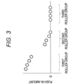
- FIG. 3 is a schematic view of push-in amounts in the shaping device 1.
- the ordinate represents the push-in amount
- the values at higher positions in the drawing represents larger positive values, and the minimum value is zero.
- the abscissa in FIG. 3 indicates the X-coordinate value of the position where the shaping device 1 is pushed in, and the left side in the drawing indicates the upstream side and the right side in the drawing indicates the downstream side.
- the push-in amount sequentially decreases from the upstream side to the downstream side and reaches zero.
- the push-in amounts in the third roller group 13 are all zero.
- the ratio between the minimum push-in amount in the first roller group 11 and the maximum push-in amount in the second roller group 12 is several times, but may be 10 times or more or 50 times or more.
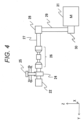
- FIG. 4 is a diagram illustrating an example of the configuration of each roller constituting the first roller group 11, that is, a driving roller.
- a driving roller 22 is driven by obtaining power energy from a motor 31 illustrated at the lower right in FIG. 4 .
- the rotational energy generated by the motor 31 is transmitted to a shaft 27 via a timing pulley 30, a timing belt 29, and a timing pulley 28.
- the position of the driving roller 22 can be adjusted as described above, and in FIG. 4 , the position can be adjusted in the Z direction by a shaft sliding screw 25 and a shaft sliding box 24.
- a universal joint 26 is interposed between the shaft 27 and the driving roller 22 so as to cope with this position adjustment.
- a procedure for determining the push-in amounts in other words, a procedure for determining the interval between the rollers, in the first roller group 11 and the second roller group 12 will be described. Since all the rollers of the third roller group 13 have a push-in amount of zero as described above, the roller interval is the same as the defined dimension of the wire material, and thus a description thereof will be omitted here.
- the first roller group 11 is adjusted first, and then the second roller group 12 is adjusted.
- the adjustment described below may be executed by, for example, an operator or may be calculated by a computer.
- a strain corresponding to "tensile strength" that is the maximum stress in the wire material is specified from the composition of the wire material.
- a physical property table or a database can be used.
- the product between the specified strain and a predetermined ratio, for example, "0.6" is calculated and is referred to as a "target strain”.
- the push-in amount of each roller in the first roller group 11 is determined so that the push-in amount sequentially decreases and the "target strain" is obtained when the first step is completed.
- the result of calculation using simulation software may be used, or the results of one or a plurality of experiments using the shaping device 1 may be used.
- the position of the first roller group 11 can be determined according to a predetermined policy.
- the predetermined policy includes, for example, fixing the position of a lower roller of the first roller group 11 and adjusting the position of an upper roller to set a roller interval to the determined value.
- the first roller group 11 is set at the determined position of the first roller group 11, and the process proceeds to the next determination processing of the push-in amount of the second roller group 12.
- the push-in amount in the second roller group 12 is determined by the placement angle ⁇ x.
- the optimum placement angle ⁇ x is determined, for example, by the operator changing xx in a plurality of ways and actually measuring the processing result of the second step. Specific examples will be described below.
- FIG. 5 is a conceptual diagram of a test result for determining the placement angle ⁇ x.
- the ordinate represents the amount of warpage
- the abscissa represents the placement angle ⁇ x.
- the placement angle ⁇ x is represented by eight angles S1 to S8, but these eight angles are merely examples, and the number of angles may be larger or smaller than eight.
- An amount of warpage on the positive side of the Z-axis means warpage toward the positive side of the Z-axis
- an amount of warpage on the negative side of the Z-axis means warpage toward the negative side of the Z-axis.
- FIG. 5 shows two independent test results. The plotted triangles show a case where the wire material output from the first step is largely biased to the positive side, and the plotted squares show a case where the wire material output from the first step is largely biased to the negative side.
- the straightening of the warpage in the second step does not work much and the value is still a large positive value in a case where the placement angle ⁇ x is the small angle S1.
- the amount of warpage decreases as the placement angle ⁇ x increases, and in the example illustrated in FIG. 5 , the amount of warpage is substantially zero when the placement angle ⁇ x. is the angle S4.
- the placement angle ⁇ x is further increased from the angle S4, the amount of warpage turns to increase and continues to increase.
- the operator determines the angle S4 corresponding to the smallest absolute value of the amount of warpage as the placement angle ⁇ x.
- the straightening of the warpage in the second step does not work much and the value is still a large negative value in a case where the placement angle ⁇ x is the small angle S1.
- the amount of warpage decreases as the placement angle ⁇ x approaches zero, and in the example illustrated in FIG. 5 , the amount of warpage is substantially zero when the placement angle ⁇ x is the angle S5.
- the placement angle ⁇ x is further increased from the angle S5, the amount of warpage continues to increase and becomes a large positive value.
- the operator determines the angle S5 corresponding to the smallest absolute value of the amount of warpage as the placement angle ⁇ x.
- the above-described embodiment may be modified as in the following ⁇ 1> to ⁇ 5>, and ⁇ 1> to ⁇ 5> may be arbitrarily combined. That is, all the modifications of ⁇ 1> to ⁇ 4> may be added to the configuration of the embodiment, or any one or more modifications of ⁇ 1> to ⁇ 5> may be added.
- the reduction of the warpage is insufficient and a disadvantage that the stability is lacking as compared with the above-described embodiment, but the adjustment of a roller position becomes easy.
- these disadvantages may exist as long as the required accuracy is satisfied.
- the method of determining the push-in amount in the second roller group 12 described in the above-described embodiment is merely an example.
- the position of each upper roller of the second roller group 12 may be individually adjustable, and the amount of warpage may be measured while changing the position of each roller little by little to determine the position of the roller corresponding to the smallest amount of warpage.
- the number of times of roller position adjustment and the number of times of measuring the amount of warpage significantly increase as compared with the embodiment, but there is a possibility that the absolute value of the amount of warpage can be made smaller than that in the embodiment.
Landscapes
- Engineering & Computer Science (AREA)
- Mechanical Engineering (AREA)
- Wire Processing (AREA)
Abstract
Description
- The present invention relates to a method for shaping a wire material and a wire material shaping device.
- A metal wire material is generally wound around a bobbin in a manufacturing process. In processing this wire material, a process called "shaping" or "straightening" for reducing warpage caused by winding is required.
Patent Literature 1 discloses a rod wire material straightener that easily improves the straightness of a rod wire material and performs straightening by passing a metal rod wire material between a plurality of rolls. This straightener is characterized as follows. The straightener includes at least one unit group including two or more adjacent units, with the directions of straightening the rod wire material of the two or more units forming an angle of ±15 °. The unit includes two or more fixed rolls and movable rolls fewer than the fixed rolls by one. The fixed rolls and the movable rolls are arranged in a staggered manner so as to sandwich the running rod wire material with the fixed rolls arranged on one side of the running rod wire material and the movable rolls arranged on a side opposite to the fixed rolls with respect to the rod wire material. The push-in amounts of the movable roll closest to the inlet side and the movable roll closest to the outlet side of each unit can be set, and the push-in amounts of the adjacent units satisfy a predetermined relationship. - PTL:
WO 2018/174272 - In the invention described in
PTL 1, there is room for improvement in shaping. - A method for shaping a wire material according to the first aspect of the present invention is a method for shaping a wire material that moves from an upstream side to a downstream side which includes a first step of feeding the wire material while pressing the wire material by a first roller group including a plurality of rollers driven by a motor and a second step of feeding the wire material while pressing the wire material by a second roller group including a plurality of rotatably supported rollers. The first step is provided upstream side of the second step. A push-in amount that is the difference between the outer dimension of the wire material and the gap between rollers through which the wire material passes is larger in the first step than in the second step.
- A wire material shaping device according to the second aspect of the present invention includes a feeding unit that feeds a wire material, a first roller group including a plurality of rollers driven by a motor to press the wire material fed by the feeding unit and a second roller group that includes a plurality of rollers configured to further press the wire material pressed by the first roller group and is rotatably supported. A push-in amount that is the difference between the outer dimension of the wire material and the gap between rollers through which the wire material passes is larger in the first roller group than in the second roller group.
- Advantageous Effects of Invention
- According to the present invention, the warpage of a wire material can be stably reduced.
-
- [
FIG. 1] FIG. 1 is a schematic diagram of a wire material processing system including a shaping device. - [
FIG. 2] FIG. 2 is a schematic configuration diagram of the shaping device. - [
FIG. 3] FIG. 3 is a schematic view of push-in amounts in the shaping device. - [
FIG. 4] FIG. 4 is a diagram illustrating an example of the configuration of a driving roller. - [
FIG. 5] FIG. 5 is a conceptual diagram of a test result for determining a placement angle θx. - Hereinafter, an embodiment of a wire material shaping device and a method for shaping a wire material according to the present invention will be described with reference to
FIGS. 1 to 5 . -
FIG. 1 is a schematic view of a wire material processing system S including ashaping device 1.FIG. 1 illustrates the X-, Y-, and Z-axes orthogonal to each other for the sake of explanation. The X-axis is parallel to the left-right direction inFIG. 1 , and the right side in the drawing is a positive direction. The Z-axis is parallel to the up-down direction inFIG. 1 , and the upward direction in the drawing is a positive direction. With regard to the Y-axis, the depth direction inFIG. 1 is a positive direction. - The wire material processing system S includes a
feeding device 700, theshaping device 1, apeeling device 800, and acutting device 900. The wire material moves from left to right in the drawing and is processed in order. Hereinafter, the left side in the drawing is also referred to as "upstream", and the right side in the drawing is also referred to as "downstream". - In the .
feeding device 700, a bobbin around which a wire material is wound is placed with its rotation axis parallel to the Y-axis. Thefeeding device 700 feeds the wire material wound around the bobbin to theshaping device 1. The wire material is warped in the Z direction inFIG. 1 by being wound around the bobbin. Theshaping device 1 straightens the warpage of the wire material in the Z direction fed from thefeeding device 700 and feeds the wire material to thepeeling device 800. The "warpage" is also called "bend" or "warping tendency". - The
peeling device 800 peels the insulating coating of the wire material by cutting, laser irradiation, or the like. Thecutting device 900 cuts the wire material to a predetermined length. Hereinafter, the configuration and operation of theshaping device 1 will be described in detail. Note that, referring toFIG. 1 , it is for convenience of drawing that the wire material is drawn in a straight line and is not an essential constituent element. -
FIG. 2 . is a schematic configuration diagram of theshaping device 1. Theshaping device 1 includes afirst roller group 11, asecond roller group 12, and athird roller group 13. The wire material is first shaped by thefirst roller group 11, then shaped by thesecond roller group 12, and finally shaped by thethird roller group 13. Hereinafter, the shaping of the wire material by thefirst roller group 11 is referred to as a "first step", the shaping of the wire material by thesecond roller group 12 is referred to as a "second step", and the shaping of the wire material by thethird roller group 13 is referred to as a "third step". In both the first step and the second step, the wire material is plastically deformed. - In the present embodiment, the difference between the outer dimension of a predetermined wire material and the gap between rollers through which the wire material passes is referred to as a "push-in amount". For example, when the outer dimension of the predetermined wire material is "1.000 mm" and the roller interval is "0.998 mm", the push-in amount is "0.002 mm".
- The
first roller group 11, thesecond roller group 12, and thethird roller group 13 each have rollers arranged in upper and lower two rows, and a wire material passes through substantially the center thereof. Thefirst roller group 11, thesecond roller group 12, and thethird roller group 13 each include at least three rollers. Thefirst roller group 11, thesecond roller group 12, and thethird roller group 13 may include different numbers of rollers. Referring toFIG. 2 , all the rollers in the lower rows of thefirst roller group 11, thesecond roller group 12, and thethird roller group 13 are arranged in a straight line, but this is merely an example of the configuration. - Each roller of the
first roller group 11 is a driving roller whose outer periphery is molded with urethane rubber and driven by a motor as described later. The direction in which each roller is driven is a direction along the movement of the wire material. Specifically, the upper rollers in the drawing are driven counterclockwise, and the lower rollers in the drawing are driven clockwise. The gap between the rollers through which the wire material passes in thefirst roller group 11 is set such that the push-in amount sequentially decreases from the upstream side to the downstream side. Hereinafter, the gap between the rollers through which the wire material passes is also referred to as a "roller interval". - Each roller of the
second roller group 12 and thethird roller group 13 is made of metal and is not driven by external power. The interval between the rollers of thesecond roller group 12 is set such that the push-in amount sequentially decreases from the upstream side to the downstream side, and the final push-in amount in thesecond roller group 12 is set to zero. The push-in amount on the most upstream of thesecond roller group 12 is smaller than the push-in amount on the most downstream of thefirst roller group 11. The push-in amounts in thethird roller group 13 are all set to zero. - The
second roller group 12 is configured such that the plurality of rollers in the upper row are integrally fixed and are rotatable about the roller at the end of the upper row as an axis. The position of the roller at the end of the upper row is determined in advance so that the last push-in amount in thesecond roller group 12 becomes zero, and the position of the roller is not readjusted unless the wire material is changed. In the present embodiment, the angle formed by a straight line connecting the centers of the rollers in the upper row of thesecond roller group 12 and a straight line connecting the centers of the rollers in the lower row of thesecond roller group 12 is referred to as a "placement angle θx ". Assume that the placement angle θx is 0°, although this can occur only in the process of adjustment to be described later. In this case, the upper row and the lower row are parallel, and the push-in amounts in thesecond roller group 12 are all zero. In thesecond roller group 12 in a state where the adjustment is completed and the wire material is shaped, the placement angle θx is set such that the push-in amount becomes larger toward the upstream side. -
FIG. 3 is a schematic view of push-in amounts in theshaping device 1. Referring toFIG. 3 , the ordinate represents the push-in amount, and the values at higher positions in the drawing represents larger positive values, and the minimum value is zero. The abscissa inFIG. 3 indicates the X-coordinate value of the position where theshaping device 1 is pushed in, and the left side in the drawing indicates the upstream side and the right side in the drawing indicates the downstream side. In thefirst roller group 11 and the. second roller group as a whole, the push-in amount sequentially decreases from the upstream side to the downstream side and reaches zero. The push-in amounts in thethird roller group 13 are all zero. Referring toFIG. 3 , the ratio between the minimum push-in amount in thefirst roller group 11 and the maximum push-in amount in thesecond roller group 12 is several times, but may be 10 times or more or 50 times or more. -
FIG. 4 is a diagram illustrating an example of the configuration of each roller constituting thefirst roller group 11, that is, a driving roller. A drivingroller 22 is driven by obtaining power energy from amotor 31 illustrated at the lower right inFIG. 4 . The rotational energy generated by themotor 31 is transmitted to ashaft 27 via a timingpulley 30, atiming belt 29, and a timingpulley 28. The position of the drivingroller 22 can be adjusted as described above, and inFIG. 4 , the position can be adjusted in the Z direction by ashaft sliding screw 25 and ashaft sliding box 24. Auniversal joint 26 is interposed between theshaft 27 and the drivingroller 22 so as to cope with this position adjustment. - A procedure for determining the push-in amounts, in other words, a procedure for determining the interval between the rollers, in the
first roller group 11 and thesecond roller group 12 will be described. Since all the rollers of thethird roller group 13 have a push-in amount of zero as described above, the roller interval is the same as the defined dimension of the wire material, and thus a description thereof will be omitted here. As described below, thefirst roller group 11 is adjusted first, and then thesecond roller group 12 is adjusted. The adjustment described below may be executed by, for example, an operator or may be calculated by a computer. - In the determination of the push-in amount in the
first roller group 11, first, a strain corresponding to "tensile strength" that is the maximum stress in the wire material is specified from the composition of the wire material. For this specification, for example, a physical property table or a database can be used. Next, the product between the specified strain and a predetermined ratio, for example, "0.6" is calculated and is referred to as a "target strain". The push-in amount of each roller in thefirst roller group 11 is determined so that the push-in amount sequentially decreases and the "target strain" is obtained when the first step is completed. For this determination, the result of calculation using simulation software may be used, or the results of one or a plurality of experiments using theshaping device 1 may be used. - If the push-in amount of each roller in the
first roller group 11 can be determined by the above procedure, the position of thefirst roller group 11 can be determined according to a predetermined policy. The predetermined policy includes, for example, fixing the position of a lower roller of thefirst roller group 11 and adjusting the position of an upper roller to set a roller interval to the determined value. Thefirst roller group 11 is set at the determined position of thefirst roller group 11, and the process proceeds to the next determination processing of the push-in amount of thesecond roller group 12. - The push-in amount in the
second roller group 12 is determined by the placement angle θx. The optimum placement angle θx is determined, for example, by the operator changing xx in a plurality of ways and actually measuring the processing result of the second step. Specific examples will be described below. -
FIG. 5 is a conceptual diagram of a test result for determining the placement angle θx. Referring toFIG. 5 , the ordinate represents the amount of warpage, and the abscissa represents the placement angle θx. Referring toFIG. 5 , the placement angle θx is represented by eight angles S1 to S8, but these eight angles are merely examples, and the number of angles may be larger or smaller than eight. An amount of warpage on the positive side of the Z-axis means warpage toward the positive side of the Z-axis, and an amount of warpage on the negative side of the Z-axis means warpage toward the negative side of the Z-axis.FIG. 5 shows two independent test results. The plotted triangles show a case where the wire material output from the first step is largely biased to the positive side, and the plotted squares show a case where the wire material output from the first step is largely biased to the negative side. - In a case where the wire material output from the first step is largely biased to the positive side as indicated by the plotted triangles, it is indicated that the straightening of the warpage in the second step does not work much and the value is still a large positive value in a case where the placement angle θx is the small angle S1. The amount of warpage decreases as the placement angle θx increases, and in the example illustrated in
FIG. 5 , the amount of warpage is substantially zero when the placement angle θx. is the angle S4. When the placement angle θx is further increased from the angle S4, the amount of warpage turns to increase and continues to increase. When the results of the plotted triangles shown inFIG. 5 are obtained, the operator determines the angle S4 corresponding to the smallest absolute value of the amount of warpage as the placement angle θx. - In a case where the wire material output from the first step is largely biased to the negative side as indicated by the plotted squares, it is indicated that the straightening of the warpage in the second step does not work much and the value is still a large negative value in a case where the placement angle θx is the small angle S1. The amount of warpage decreases as the placement angle θx approaches zero, and in the example illustrated in
FIG. 5 , the amount of warpage is substantially zero when the placement angle θx is the angle S5. When the placement angle θx is further increased from the angle S5, the amount of warpage continues to increase and becomes a large positive value. When the results of the plotted squares shown inFIG. 5 are obtained, the operator determines the angle S5 corresponding to the smallest absolute value of the amount of warpage as the placement angle θx. - According to the embodiment described above, the following operational effects can be obtained.
- (1) The
shaping device 1 shapes a wire material moving from the upstream side corresponding to the left side inFIG. 2 to the downstream side corresponding to the right side inFIG. 2 as follows. The wire material shaping by theshaping device 1 includes the following first step and second step. In the first step, the wire material is fed while being pressed by thefirst roller group 11 which is a plurality of rollers driven by themotor 31. In the second step, the wire material is fed while being pressed by thesecond roller group 12 which is a plurality of rotatably supported rollers. The first step is provided upstream side of the second step, that is, on the left side in the drawing. The push-in amount, which is the difference between the outer dimension of the wire material and the gap between the rollers through which the wire material passes, is larger in the first step than in the second step. Therefore, in the first step, by feeding the wire material using the drivenfirst roller group 11, the tension generated in the wire material is reduced to reduce the warpage while suppressing the elongation, and in the second step, by setting the push-in amount to be lower than that in the first step, the warpage of the wire material can be stably reduced. That is, the warpage of the wire material can be stably reduced by the shaping method by theshaping device 1. - (2) In the first step, the push-in amount sequentially decreases from the upstream side to the downstream side. Accordingly, the warpage of the wire material can be more stably reduced.
- (3) In the second step, the push-in amount sequentially decreases to zero from the upstream side to the downstream side. Accordingly, the warpage of the wire material can be more stably reduced.
- (4) The minimum push-in amount in the first step is at least 10 times the maximum push-in amount in the second step. Therefore, in the first step, a strong strain is applied to the wire material, and mechanical properties can be made uniform by work hardening.
- (5) The shaping of the wire material by the
shaping device 1 includes a third step of feeding the wire material by thethird roller group 13, which includes a plurality of rotatably supported rollers, in addition to the first step and the second step. The third step is provided downstream of the second step, that is, on the right side in the drawing. The push-in amount in the third step is zero. Therefore, using thethird roller group 13 in which the push-in amount is zero makes it possible to straighten the warpage of the wire material itself and suppress the variation. - (6) Each of the rollers constituting the
first roller group 11 has a surface made of urethane rubber. Accordingly, the followability of the wire material to each driving roller is improved, and the warpage of the wire material can be further reduced. - The above-described embodiment may be modified as in the following <1> to <5>, and <1> to <5> may be arbitrarily combined. That is, all the modifications of <1> to <4> may be added to the configuration of the embodiment, or any one or more modifications of <1> to <5> may be added.
-
- <1> The
shaping device 1 may not include thethird roller group 13 and may not include the third step in the shaping of the wire material. - <2> The ratio between the minimum push-in amount in the first step and the maximum push-in amount in the second step may be several times.
- <3> In the first step, the push-in amount may not sequentially decrease from the upstream side to the downstream side.
- <4> In the second step, the push-in amount may not sequentially decrease from the upstream side to the downstream side.
- <5> The rollers constituting the
first roller group 11 each may have a surface made of a metal without molding urethane rubber on the outer periphery. - According to the first modification, there are a disadvantage that the reduction of the warpage is insufficient and a disadvantage that the stability is lacking as compared with the above-described embodiment, but the adjustment of a roller position becomes easy. In addition, these disadvantages may exist as long as the required accuracy is satisfied.
- The method of determining the push-in amount in the
second roller group 12 described in the above-described embodiment is merely an example. For example, the position of each upper roller of thesecond roller group 12 may be individually adjustable, and the amount of warpage may be measured while changing the position of each roller little by little to determine the position of the roller corresponding to the smallest amount of warpage. In this case, the number of times of roller position adjustment and the number of times of measuring the amount of warpage significantly increase as compared with the embodiment, but there is a possibility that the absolute value of the amount of warpage can be made smaller than that in the embodiment. - Although various embodiments and modifications have been described above, the present invention is not limited to these contents. Other aspects conceivable within the scope of the technical idea of the present invention are also included within the scope of the present invention.
-
- 1
- shaping device
- 11
- first roller group
- 12
- second roller group
- 13
- third roller group
- 31
- motor
Claims (12)
- A method for shaping a wire material that moves from an upstream side to a downstream side, the method comprising:a first step of feeding the wire material while pressing the wire material by a first roller group including a plurality of rollers driven by a motor; anda second step of feeding the wire material while pressing the wire material by a second roller group including a plurality of rotatably supported rollers, whereinthe first step is provided upstream of the second step, anda push-in amount that is a difference between an outer dimension of the wire material and a gap between rollers through which the wire material passes is larger in the first step than in the second step.
- The method for shaping a wire material according to claim 1, wherein in the first step, the push-in amount sequentially decreases from the upstream side to the downstream side.
- The method for shaping a wire material according to claim 1, wherein in the second step, the push-in amount sequentially decreases to zero from the upstream side, to the downstream side.
- The method for shaping a wire material according to claim 1, wherein a minimum push-in amount in the first step is at least 10 times as large as a maximum push-in amount in the second step.
- The method for shaping a wire material according to claim 1, further comprising a third step of feeding the wire material by a third roller group including a plurality of rotatably supported rollers, whereinthe third step is provided downstream of the second step, andthe push-in amount in the third step is zero.
- The method for shaping a wire material according to claim 1, wherein a surface of each roller constituting the first roller group is urethane rubber.
- A wire material shaping device comprising:a feeding unit that feeds a wire material;a first roller group including a plurality of rollers driven by a motor to press the wire material fed by the feeding unit; anda second roller group that includes a plurality of rollers configured to further press the wire material pressed by the first roller group and is rotatably supported, wherein a push-in amount that is a difference between an outer dimension of the wire material and a gap between rollers through which the wire material passes is larger in the first roller group than in the second roller group.
- The wire material shaping device according to claim 7, whereinthe first roller group is placed between the feeding unit and the second roller group, andthe push-in amount in the first roller group sequentially decreases from the feeding unit to the second roller group.
- The wire material shaping device according to claim 7, wherein the push-in amount in the second roller group sequentially decreases to zero from the first roller group to an opposite side.
- The wire material shaping device according to claim 7, wherein a minimum push-in amount in the first roller group is at least 10 times a maximum push-in amount in the second roller group.
- The wire material shaping device according to claim 7, further comprising a third roller group rotatably supported and including a plurality of rollers that further press the wire material pressed by the second roller group, wherein the push-in amount in the third roller group is zero.
- The wire material shaping device according to claim 7, wherein a surface of each roller constituting the first roller group is urethane rubber.
Applications Claiming Priority (2)
| Application Number | Priority Date | Filing Date | Title |
|---|---|---|---|
| JP2021030265 | 2021-02-26 | ||
| PCT/JP2021/038485 WO2022180925A1 (en) | 2021-02-26 | 2021-10-18 | Method for molding wire material, device for molding wire material |
Publications (2)
| Publication Number | Publication Date |
|---|---|
| EP4299206A1 true EP4299206A1 (en) | 2024-01-03 |
| EP4299206A4 EP4299206A4 (en) | 2025-01-15 |
Family
ID=83047938
Family Applications (1)
| Application Number | Title | Priority Date | Filing Date |
|---|---|---|---|
| EP21928020.3A Pending EP4299206A4 (en) | 2021-02-26 | 2021-10-18 | Method for molding wire material, device for molding wire material |
Country Status (5)
| Country | Link |
|---|---|
| US (1) | US20240299996A1 (en) |
| EP (1) | EP4299206A4 (en) |
| JP (1) | JP7567023B2 (en) |
| CN (1) | CN116783015A (en) |
| WO (1) | WO2022180925A1 (en) |
Family Cites Families (20)
| Publication number | Priority date | Publication date | Assignee | Title |
|---|---|---|---|---|
| JPS5236105B2 (en) * | 1972-05-08 | 1977-09-13 | ||
| JPS60151643U (en) * | 1984-03-16 | 1985-10-08 | 株式会社明電舎 | Electric wire leveler |
| JPS6146036U (en) * | 1984-08-24 | 1986-03-27 | 電気興業株式会社 | Line removing device |
| JP2759988B2 (en) * | 1988-10-29 | 1998-05-28 | 大同特殊鋼株式会社 | Automatic positioning device for straightening roller |
| JP2518842Y2 (en) * | 1991-04-09 | 1996-11-27 | 古河電気工業株式会社 | Shaping device for stranded conductor with fins |
| JP2981038B2 (en) * | 1991-10-16 | 1999-11-22 | 株式会社ブリヂストン | Method for correcting residual stress and straightness of metal wire |
| JPH06246380A (en) * | 1993-03-02 | 1994-09-06 | Hitachi Ltd | Wire rope straightening method and device |
| CN2302068Y (en) * | 1996-12-30 | 1998-12-30 | 郑克孝 | Cold-rolled ribbed reinforcing steel straightening machine |
| JP2001353542A (en) * | 2000-06-12 | 2001-12-25 | Nittetsu Steel Pipe Co Ltd | Drawing method and apparatus for galvanized steel pipe |
| ITBO20040042A1 (en) * | 2004-02-02 | 2004-05-02 | Unimac Srl | METHOD AND EQUIPMENT FOR STRAIGHTENING ONE OR MORE WIRES |
| JP2007044734A (en) | 2005-08-10 | 2007-02-22 | Hitachi Cable Ltd | Wire straightening device and solar cell assembly wiring device |
| JP2007229745A (en) * | 2006-02-28 | 2007-09-13 | Furukawa Electric Co Ltd:The | Wire flaw removal method and electric wire flaw removal apparatus |
| FR2937267B1 (en) * | 2008-10-17 | 2010-11-12 | Dimeco Alipresse | DEVICE FOR RECOVERING AND MAINTAINING A BAND OF SEMI-RIGID MATERIAL IN A MACHINE |
| CN102366803B (en) * | 2010-06-23 | 2015-09-02 | 科马斯控股股份公司 | For aligning the straightener of cable and corresponding method |
| JP5853578B2 (en) * | 2011-10-20 | 2016-02-09 | 住友電装株式会社 | Electric wire straightening device |
| CN202683859U (en) * | 2012-08-01 | 2013-01-23 | 大连伯新特钢制品有限公司 | Ventilation channel steel straightening machine |
| CN203209583U (en) * | 2012-10-19 | 2013-09-25 | 株式会社神户制钢所 | Welding wire straightening device |
| JP6445370B2 (en) * | 2015-03-30 | 2018-12-26 | 矢崎総業株式会社 | Wire straightener |
| CN110234444A (en) * | 2017-03-24 | 2019-09-13 | 日本制铁株式会社 | The straightener of Bar Wire Product and the method for aligning of Bar Wire Product |
| CN109226587B (en) * | 2018-09-25 | 2024-05-03 | 建科机械(天津)股份有限公司 | Steel bar bending machine |
-
2021
- 2021-10-18 EP EP21928020.3A patent/EP4299206A4/en active Pending
- 2021-10-18 US US18/547,531 patent/US20240299996A1/en active Pending
- 2021-10-18 WO PCT/JP2021/038485 patent/WO2022180925A1/en not_active Ceased
- 2021-10-18 CN CN202180092750.4A patent/CN116783015A/en active Pending
- 2021-10-18 JP JP2023502059A patent/JP7567023B2/en active Active
Also Published As
| Publication number | Publication date |
|---|---|
| US20240299996A1 (en) | 2024-09-12 |
| JPWO2022180925A1 (en) | 2022-09-01 |
| JP7567023B2 (en) | 2024-10-15 |
| WO2022180925A1 (en) | 2022-09-01 |
| CN116783015A (en) | 2023-09-19 |
| EP4299206A4 (en) | 2025-01-15 |
Similar Documents
| Publication | Publication Date | Title |
|---|---|---|
| US8302275B2 (en) | Iron core and method of manufacturing the same and apparatus for manufacturing the same | |
| US20110018674A1 (en) | Transformer, and apparatus and method for manufacturing a transformer iron core | |
| CN110402172B (en) | Method for operating a roller straightener and roller straightener | |
| US11904369B2 (en) | Apparatus and methods using the apparatus for treating metal wire | |
| US10525515B2 (en) | Roll-bending processing method and processing device | |
| KR20150137989A (en) | Drawing unit and corresponding method | |
| CN101568975A (en) | Insulated wire manufacturing method and manufacturing device thereof | |
| EP3888810B1 (en) | Method of controlling flatness of strip of rolled material, control system and production line | |
| US20240299996A1 (en) | Method for shaping wire material and wire material shaping device | |
| WO2020110442A1 (en) | Processing device, and method for controlling processing device | |
| KR101328360B1 (en) | Method of setting roller leveler | |
| US10236753B2 (en) | Method of manufacturing assembled conductor and electric motor | |
| JPH05104181A (en) | Method for correcting residual stress and straightness in metal wire rod | |
| JP4059737B2 (en) | Roll bending method and roll bending apparatus | |
| WO2018174272A1 (en) | Wire rod straightening machine and method for straightening wire rod | |
| JP4398444B2 (en) | Iron core manufacturing method and iron core manufacturing apparatus | |
| KR101406446B1 (en) | Apparatus for shear deforming | |
| JP2014140866A (en) | Processing apparatus and processing method for long workpiece | |
| JP2004034113A (en) | Roller leveler and roller straightening method | |
| JP5551551B2 (en) | Method for producing rubber-cord composite | |
| JP2011147977A (en) | Method of producing copper strip material having deformed cross section | |
| CN114570789A (en) | Straightening device, tensioning roller group thereof, straightening device and method for operating straightening device | |
| JPH0631609Y2 (en) | Overhead insulated wire manufacturing equipment | |
| JPH07150313A (en) | Method and apparatus for manufacturing semi-hard wire | |
| JPH04327318A (en) | Shape straightening method for extremely thin metallic strip |
Legal Events
| Date | Code | Title | Description |
|---|---|---|---|
| STAA | Information on the status of an ep patent application or granted ep patent |
Free format text: STATUS: THE INTERNATIONAL PUBLICATION HAS BEEN MADE |
|
| PUAI | Public reference made under article 153(3) epc to a published international application that has entered the european phase |
Free format text: ORIGINAL CODE: 0009012 |
|
| STAA | Information on the status of an ep patent application or granted ep patent |
Free format text: STATUS: REQUEST FOR EXAMINATION WAS MADE |
|
| 17P | Request for examination filed |
Effective date: 20230926 |
|
| AK | Designated contracting states |
Kind code of ref document: A1 Designated state(s): AL AT BE BG CH CY CZ DE DK EE ES FI FR GB GR HR HU IE IS IT LI LT LU LV MC MK MT NL NO PL PT RO RS SE SI SK SM TR |
|
| DAV | Request for validation of the european patent (deleted) | ||
| DAX | Request for extension of the european patent (deleted) | ||
| A4 | Supplementary search report drawn up and despatched |
Effective date: 20241216 |
|
| RIC1 | Information provided on ipc code assigned before grant |
Ipc: B21F 1/02 20060101AFI20241210BHEP |
|
| RAP3 | Party data changed (applicant data changed or rights of an application transferred) |
Owner name: ASTEMO, LTD. |
|
| STAA | Information on the status of an ep patent application or granted ep patent |
Free format text: STATUS: EXAMINATION IS IN PROGRESS |
|
| 17Q | First examination report despatched |
Effective date: 20251030 |
|
| GRAP | Despatch of communication of intention to grant a patent |
Free format text: ORIGINAL CODE: EPIDOSNIGR1 |
|
| STAA | Information on the status of an ep patent application or granted ep patent |
Free format text: STATUS: GRANT OF PATENT IS INTENDED |
|
| INTG | Intention to grant announced |
Effective date: 20260629 |