EP4299205A1 - Notching apparatus for electrode substrate of rechargeable battery - Google Patents
Notching apparatus for electrode substrate of rechargeable battery Download PDFInfo
- Publication number
- EP4299205A1 EP4299205A1 EP23182725.4A EP23182725A EP4299205A1 EP 4299205 A1 EP4299205 A1 EP 4299205A1 EP 23182725 A EP23182725 A EP 23182725A EP 4299205 A1 EP4299205 A1 EP 4299205A1
- Authority
- EP
- European Patent Office
- Prior art keywords
- blade
- punch
- hook
- die
- notching apparatus
- Prior art date
- Legal status (The legal status is an assumption and is not a legal conclusion. Google has not performed a legal analysis and makes no representation as to the accuracy of the status listed.)
- Granted
Links
Images




Classifications
-
- B—PERFORMING OPERATIONS; TRANSPORTING
- B26—HAND CUTTING TOOLS; CUTTING; SEVERING
- B26F—PERFORATING; PUNCHING; CUTTING-OUT; STAMPING-OUT; SEVERING BY MEANS OTHER THAN CUTTING
- B26F1/00—Perforating; Punching; Cutting-out; Stamping-out; Apparatus therefor
- B26F1/38—Cutting-out; Stamping-out
- B26F1/44—Cutters therefor; Dies therefor
-
- B—PERFORMING OPERATIONS; TRANSPORTING
- B26—HAND CUTTING TOOLS; CUTTING; SEVERING
- B26F—PERFORATING; PUNCHING; CUTTING-OUT; STAMPING-OUT; SEVERING BY MEANS OTHER THAN CUTTING
- B26F1/00—Perforating; Punching; Cutting-out; Stamping-out; Apparatus therefor
- B26F1/02—Perforating by punching, e.g. with relatively-reciprocating punch and bed
- B26F1/12—Perforating by punching, e.g. with relatively-reciprocating punch and bed to notch margins of work
-
- B—PERFORMING OPERATIONS; TRANSPORTING
- B21—MECHANICAL METAL-WORKING WITHOUT ESSENTIALLY REMOVING MATERIAL; PUNCHING METAL
- B21D—WORKING OR PROCESSING OF SHEET METAL OR METAL TUBES, RODS OR PROFILES WITHOUT ESSENTIALLY REMOVING MATERIAL; PUNCHING METAL
- B21D28/00—Shaping by press-cutting; Perforating
- B21D28/02—Punching blanks or articles with or without obtaining scrap; Notching
-
- B—PERFORMING OPERATIONS; TRANSPORTING
- B21—MECHANICAL METAL-WORKING WITHOUT ESSENTIALLY REMOVING MATERIAL; PUNCHING METAL
- B21D—WORKING OR PROCESSING OF SHEET METAL OR METAL TUBES, RODS OR PROFILES WITHOUT ESSENTIALLY REMOVING MATERIAL; PUNCHING METAL
- B21D45/00—Ejecting or stripping-off devices arranged in machines or tools dealt with in this subclass
- B21D45/003—Ejecting or stripping-off devices arranged in machines or tools dealt with in this subclass in punching machines or punching tools
-
- B—PERFORMING OPERATIONS; TRANSPORTING
- B21—MECHANICAL METAL-WORKING WITHOUT ESSENTIALLY REMOVING MATERIAL; PUNCHING METAL
- B21D—WORKING OR PROCESSING OF SHEET METAL OR METAL TUBES, RODS OR PROFILES WITHOUT ESSENTIALLY REMOVING MATERIAL; PUNCHING METAL
- B21D45/00—Ejecting or stripping-off devices arranged in machines or tools dealt with in this subclass
- B21D45/02—Ejecting devices
- B21D45/04—Ejecting devices interrelated with motion of tool
-
- B—PERFORMING OPERATIONS; TRANSPORTING
- B26—HAND CUTTING TOOLS; CUTTING; SEVERING
- B26D—CUTTING; DETAILS COMMON TO MACHINES FOR PERFORATING, PUNCHING, CUTTING-OUT, STAMPING-OUT OR SEVERING
- B26D7/00—Details of apparatus for cutting, cutting-out, stamping-out, punching, perforating, or severing by means other than cutting
- B26D7/18—Means for removing cut-out material or waste
- B26D7/1818—Means for removing cut-out material or waste by pushing out
-
- B—PERFORMING OPERATIONS; TRANSPORTING
- B26—HAND CUTTING TOOLS; CUTTING; SEVERING
- B26F—PERFORATING; PUNCHING; CUTTING-OUT; STAMPING-OUT; SEVERING BY MEANS OTHER THAN CUTTING
- B26F1/00—Perforating; Punching; Cutting-out; Stamping-out; Apparatus therefor
- B26F1/02—Perforating by punching, e.g. with relatively-reciprocating punch and bed
- B26F1/14—Punching tools; Punching dies
-
- B—PERFORMING OPERATIONS; TRANSPORTING
- B26—HAND CUTTING TOOLS; CUTTING; SEVERING
- B26F—PERFORATING; PUNCHING; CUTTING-OUT; STAMPING-OUT; SEVERING BY MEANS OTHER THAN CUTTING
- B26F1/00—Perforating; Punching; Cutting-out; Stamping-out; Apparatus therefor
- B26F1/38—Cutting-out; Stamping-out
- B26F1/40—Cutting-out; Stamping-out using a press, e.g. of the ram type
-
- B—PERFORMING OPERATIONS; TRANSPORTING
- B26—HAND CUTTING TOOLS; CUTTING; SEVERING
- B26F—PERFORATING; PUNCHING; CUTTING-OUT; STAMPING-OUT; SEVERING BY MEANS OTHER THAN CUTTING
- B26F1/00—Perforating; Punching; Cutting-out; Stamping-out; Apparatus therefor
- B26F1/38—Cutting-out; Stamping-out
- B26F1/44—Cutters therefor; Dies therefor
- B26F2001/4481—Cutters therefor; Dies therefor having special lateral or edge outlines or special surface shapes, e.g. apertures
-
- B—PERFORMING OPERATIONS; TRANSPORTING
- B26—HAND CUTTING TOOLS; CUTTING; SEVERING
- B26F—PERFORATING; PUNCHING; CUTTING-OUT; STAMPING-OUT; SEVERING BY MEANS OTHER THAN CUTTING
- B26F1/00—Perforating; Punching; Cutting-out; Stamping-out; Apparatus therefor
- B26F1/38—Cutting-out; Stamping-out
- B26F1/44—Cutters therefor; Dies therefor
- B26F2001/449—Cutters therefor; Dies therefor for shearing, e.g. with adjoining or abutting edges
-
- B—PERFORMING OPERATIONS; TRANSPORTING
- B26—HAND CUTTING TOOLS; CUTTING; SEVERING
- B26F—PERFORATING; PUNCHING; CUTTING-OUT; STAMPING-OUT; SEVERING BY MEANS OTHER THAN CUTTING
- B26F2210/00—Perforating, punching, cutting-out, stamping-out, severing by means other than cutting of specific products
-
- H—ELECTRICITY
- H01—ELECTRIC ELEMENTS
- H01M—PROCESSES OR MEANS, e.g. BATTERIES, FOR THE DIRECT CONVERSION OF CHEMICAL ENERGY INTO ELECTRICAL ENERGY
- H01M4/00—Electrodes
- H01M4/02—Electrodes composed of, or comprising, active material
- H01M2004/021—Physical characteristics, e.g. porosity, surface area
-
- H—ELECTRICITY
- H01—ELECTRIC ELEMENTS
- H01M—PROCESSES OR MEANS, e.g. BATTERIES, FOR THE DIRECT CONVERSION OF CHEMICAL ENERGY INTO ELECTRICAL ENERGY
- H01M4/00—Electrodes
- H01M4/02—Electrodes composed of, or comprising, active material
- H01M4/04—Processes of manufacture in general
-
- H—ELECTRICITY
- H01—ELECTRIC ELEMENTS
- H01M—PROCESSES OR MEANS, e.g. BATTERIES, FOR THE DIRECT CONVERSION OF CHEMICAL ENERGY INTO ELECTRICAL ENERGY
- H01M50/00—Constructional details or processes of manufacture of the non-active parts of electrochemical cells other than fuel cells, e.g. hybrid cells
- H01M50/10—Primary casings; Jackets or wrappings
- H01M50/102—Primary casings; Jackets or wrappings characterised by their shape or physical structure
- H01M50/105—Pouches or flexible bags
-
- Y—GENERAL TAGGING OF NEW TECHNOLOGICAL DEVELOPMENTS; GENERAL TAGGING OF CROSS-SECTIONAL TECHNOLOGIES SPANNING OVER SEVERAL SECTIONS OF THE IPC; TECHNICAL SUBJECTS COVERED BY FORMER USPC CROSS-REFERENCE ART COLLECTIONS [XRACs] AND DIGESTS
- Y02—TECHNOLOGIES OR APPLICATIONS FOR MITIGATION OR ADAPTATION AGAINST CLIMATE CHANGE
- Y02E—REDUCTION OF GREENHOUSE GAS [GHG] EMISSIONS, RELATED TO ENERGY GENERATION, TRANSMISSION OR DISTRIBUTION
- Y02E60/00—Enabling technologies; Technologies with a potential or indirect contribution to GHG emissions mitigation
- Y02E60/10—Energy storage using batteries
Definitions
- the present disclosure relates to a notching apparatus for an electrode substrate of a rechargeable battery. More particularly, the present disclosure relates to a notching apparatus for an electrode substrate of a rechargeable battery capable of discharging scraps that are generated while manufacturing an electrode by notching a continuously supplied electrode substrate.
- a rechargeable battery is a battery that repeatedly performs charging and discharging unlike a primary battery.
- Small-capacity secondary batteries are used in small portable electronic devices such as mobile phones, notebook computers, and camcorders.
- High-capacity and high-density secondary batteries are used for power or energy storage for driving motors in hybrid and electric vehicles.
- the rechargeable battery includes an electrode assembly for charging and discharging a current, a case or pouch for receiving the electrode assembly and an electrolyte solution, and an electrode terminal connected to the electrode assembly and drawn to an outside of the case or pouch.
- the electrode assembly may be formed in a jelly roll type formed by winding an electrode and a separator or in a stack type formed by stacking an electrode and a separator.
- An electrode used in a stack type rechargeable battery is manufactured by notching the electrode substrate having a coated portion and an uncoated portion.
- a notching apparatus used in a notching process of the electrode substrate typically includes a lower mold assembly having a die and an upper mold assembly having a punch. The notching apparatus manufactures the electrode by notching the electrode substrate inserted between the lower plate mold assembly and the upper plate mold assembly into a desired shape by relative ascending and/or descending operation of the die and the punch.
- scrap is generated on the lower side of the punch and the inner side of the die.
- an air method a pin method, a pusher method using a tension spring, a pusher method using a cam, and the like are used.
- the pusher moves forward by the tension spring when the mold rises, and when the pusher moves forward, a blade descends to push the scrap to the lower side of the mold.
- the rigidity of the tension spring may be deteriorated due to repetitive work, and in this case, parts may not be moved to accurate positions, which may cause an accident.
- a drive holder connected to a cam moves forward and backward by ascending or descending of the mold, and when the pusher moves forward, the bland descends to push the scrap to the lower side of the mold.
- This method may prevent take-out errors according to the driving of the mold, but the cam and pusher may be damaged when the cam and pusher are restrained by foreign substances.
- the present disclosure attempts to provide a notching apparatus for an electrode substrate of a rechargeable battery capable of smoothly discharging scrap generated while manufacturing an electrode by notching a supplied electrode substrate.
- a notching apparatus for an electrode substrate of a rechargeable battery includes a lower plate assembly provided with a die, an upper plate assembly provided with a punch facing toward the die, interposing the electrode substrate that passes (during use of the apparatus) in a first direction on the lower plate assembly and has a width in a second direction crossing the first direction, and a pusher provided to a first side of the punch and the die in the second direction, and configured to notch the electrode from the electrode substrate and separate a generated scrap by pressing with a blade, where the blade is disposed to connect an exterior and an interior of the die in the second direction, and where at least first side of the punch and the die is provided with a recess on which the blade may be laid.
- the punch may be provided with a receiving recess configured to accommodate a first end of the blade at a lower surface.
- the first end of the blade may form three branch structures corresponding to an uncoated portion at an outside or an opposite side of a tab of the electrode.
- the pusher may include an upper block configured to mount the blade at an operation center by a first hinge, and to elastically support second ends of the blade located at a second side of the operation center in a downward direction to vertically operate the first end of the blade located at a first side of the operation center, and a lower block provided in a lower side of the upper block, and configured to mount a hook coupled to or released from the first end at the operation center by a second hinge and to elastically support the hook from an exterior side to an interior side in the second direction.
- the upper block may include a first height portion formed at a low height (e.g. first height) in the interior side in the second direction and a second height portion formed at a higher height than the first height portion in the exterior side in the second direction, and configured to install the operation center of the blade located in a first through-hole vertically penetrating a boundary of the first height portion and the second height portion by the first hinge.
- a low height e.g. first height
- second height portion formed at a higher height than the first height portion in the exterior side in the second direction
- the second height portion may be provided with a first elastic member in the vertical direction, the second end of the blade is provided at a lower side of the second height portion to receive an elastic force of the first elastic member, and the first end of the blade is disposed at a lower side of the first height portion to receive a downward force of the punch.
- the lower block may be configured to install a lower end of the hook at a second through-hole provided at and vertically penetrating a lower side of the second height portion and a lower side of the boundary.
- the blade may be provided with a hook pin in the first height portion
- the lower block may be provided with a second elastic member in the second direction
- the hook may receive an elastic force of the second elastic member coupled to the hook pin as the blade descends and is disengaged from the hook pin when the blade ascends.
- the hook pin may be formed as a curved surface centered on the first direction, and the hook may protrude toward the curved surface, and may have an upper inclined surface and a lower inclined surface facing the hook pin.
- the blade may be provided with a third through-hole at an upper side of a second through-hole such that the hook is inserted in the vertical direction, and the hook pin may be installed in the third through-hole in the first direction.
- the blade may be provided with a connection portion configured to connect the first end and the third through-hole, and the connection portion may be positioned in the recess.
- a pusher configured to separate a scrap by pressing with a blade
- the blade is disposed to connect an exterior and an interior of the die
- the die or the punch is provided with a recess on which the blade may be laid. Therefore, when the electrode is manufactured by notching the supplied electrode substrate, the generated scrap may be smoothly discharged by the pusher.
- FIG. 1 is a top plan view of a notching apparatus for an electrode substrate of a rechargeable battery according to an embodiment.
- FIG. 2 is a front view according to line II-II of FIG. 1 .
- a notching apparatus of an embodiment includes a lower plate mold assembly 100 (hereinafter, referred to as a lower plate assembly, in short) provided with a die 10, an upper plate mold assembly 200 (hereinafter, referred to as an upper plate assembly, in short) provided with a punch 20, and a pusher 400.
- An upper plate assembly 200 and a lower plate assembly 100 may be interconnected to each other by a lifting member 300 that guides movement of the upper and lower plate assemblies 200 and 100 that move in opposite directions.
- the pusher 400 may be mounted on the lower panel assembly 100.
- the upper plate assembly 200 faces toward a third direction (z-axis direction) crossing a x-y plane, interposing an electrode substrate S that passes in a first direction (x-axis direction) on the lower plate assembly 100 and has a width in a second direction (y-axis direction) crossing the first direction.
- the punch 20 faces the die 10 such that the electrode substrate S in the x-y plane may be notched into the electrode E.
- the electrode substrate S is unwound from a reel state to be continuously supplied between the upper plate assembly 200 and the lower plate assembly 100, and includes a coated portion CP disposed along the x-axis direction in a middle of the y-axis direction and an uncoated portion UCP disposed along the x-axis direction at both ends in the y-axis direction.
- the die 10 provided in the lower plate assembly 100 may include a first die 110 and a second die 210 for notching in different shapes
- the punch 20 provided on the upper plate assembly 200 corresponding thereto may include a first punch 120 and a second punch 220.
- the first die 110 and the first punch 120 may be provided to a first side of the electrode substrate S in the second direction to notch a first side of the electrode E
- the second die 210 and the second punch 220 may be provided to a second side of the electrode substrate S in the second direction to notch a second side of the electrode E.
- the second die 210 and the second punch 220 are formed to notch the uncoated portion UCP to a tab T portion of the electrode E
- the first die 110 and the first punch 120 are formed to notch the opposite portion of the electrode E.
- the second die 210 and the second punch 220 will be described as an example.
- the pusher 400 is provided to a first side of the die 10 and the punch 20 in the second direction (the y-axis direction), and is configured to separate scrap SCR (refer to FIG. 3 and FIG. 6 ) generated by notching the electrode E from the electrode substrate S by pressing by a blade 410.
- the blade 410 is disposed to connect an exterior and an interior of the die 10 in the second direction (the y-axis direction).
- the die 10 and the punch 20 have recesses 11 and 12 on which the blade 410 may be laid.
- the recess may be formed only in the die or only in the punch depending on the shape of the blade 410.
- the punch 20 may have a receiving recess 21 accommodating a first end 411 of the blade 410 on a lower surface.
- the receiving recess 21 enables the first end 411 of the blade 410 disposed between the punch 20 and the die 10 to press the scrap SCR to be separated from the electrode substrate S, the electrode E, the die 10, and the punch 20, without interfering the notching process.
- the first end 411 of the blade 410 may form three branch structures corresponding to the uncoated portion UCP at an outside or an opposite side of the tab T of the electrode E.
- the three branch structures provide separation force to the scrap SCR along the first direction (the y-axis direction) at both ends of the electrode E in the second direction (the y-axis direction) that are notched, and thereby may prevent separation error of the scrap SCR.
- FIG. 3 is a perspective view showing a die, a punch, and pusher applied to a notching apparatus for an electrode substrate of a rechargeable battery of FIG. 1 .
- FIG. 4 is a perspective view of a pusher applied to FIG. 1 and FIG. 3 .
- FIG. 5 is an exploded perspective view of a pusher shown in FIG. 4 .
- FIG. 6 a top plan view showing a state in which a blade of a pusher of FIG. 4 is disposed in a die and a scrap of FIG. 3 .
- the pusher 400 may include an upper block 430 and a lower block 440.
- the upper block 430 mounts the blade 410 at an operation center by a first hinge H1, and is configured to elastically support a second end 412 of the blade 410 positioned at a second side of the operation center in downward direction, such that the first end 411 of the blade 410 positioned at a first side of the operation center may be operated in a vertical direction.
- the lower block 440 is provided at a lower side of the upper block 430, and configured to mount, at a lower end, a hook 450 coupled to or released from the first end 411 at the operation center of the blade 410 by a second hinge H2 and to elastically support the hook 450 from the exterior side to the interior side in the second direction (the y-axis direction).
- the upper block 430 may include a first height portion 431 and a second height portion 432.
- the first height portion 431 is formed at a low height in the interior side in the second direction (the y-axis direction).
- the second height portion 432 is formed in the exterior side in the second direction, at a height higher than that of the first height portion 431.
- the upper block 430 has a first through-hole 433 penetrating in the vertical direction at the boundary between the first height portion 431 and the second height portion 432, and installs the operating center of the blade 410 located at the first through-hole 433 by the first hinge H1. Accordingly, at the lower side of the upper block 430, the blade 410 forms the first end 411 in the interior side in the second direction (the y-axis direction), and forms the second end 412 in in the exterior side, having the first hinge H1 as the operation center.
- FIG. 7 is a cross-sectional view according to line VII-VII of FIG. 6 , and shows operation states of a punch and an upper block at the time of immediately before descending for the notching, during descending, during ascending after the notching, and after completing the ascending.
- the second height portion 432 may include a first elastic member 434 in the vertical direction.
- the first elastic member 434 is embedded in the second height portion 432 interposing a first push member 435 and supported by a cover 436.
- the cover 436 is coupled to a protrusion 437 formed at an upper end of the second height portion 432 through a first side, and fixed to the second height portion 432 by a bolt 438 through a second side, thereby facilitating embedding of the first elastic member 434 and the first push member 435.
- the second end 412 of the blade 410 may be provided at a lower side of the second height portion 432, and may receive a downward elastic force of the first elastic member 434 and the first push member 435. Accordingly, the first end 411 of the blade 410 may be disposed at a lower side of the first height portion 431, and may receive a downward force of the punch 20.
- the downward force of the punch 20 overcomes the elastic force of the first elastic member 434 and lowers the first end 411 of the blade 410 having the first hinge H1 as the operation center, and therefore, presses and separates the notching scrap SCR from the electrode substrate S and the electrode E.
- the lower block 440 is provided at a lower side of the second height portion 432 and a lower side of the boundary, may be provided with a second through-hole 443 penetrated in the vertical direction, and may install a lower end of the hook 450 positioned in the second through-hole 443 by the second hinge H2. Accordingly, the hook 450 operates having the second hinge H2 as its operation center.
- the blade 410 may be provided with a hook pin H3 in the first height portion 431.
- the lower block 440 may embed a second elastic member 444 in the second direction.
- the second elastic member 444 is embedded in the lower block 440 interposing the second push member 445, and fixed with a plate 448 and bolts 438.
- the hook 450 receives the elastic force of the second elastic member 444 and the second push member 445 to be coupled to the hook pin H3 when the blade 410 descends.
- the hook 450 is coupled to the hook pin H3 while receiving an elastic force, and then released by the rise of the hook pin H3.
- the hook pin H3 may be formed as a curved surface centered on the first direction (the x-axis direction).
- the hook 450 protrudes toward the curved surface of the hook pin H3 and has an upper inclined surface 452 and a lower inclined surface 451 facing the hook pin H3.
- the upper inclined surface 452 softens the engagement with the hook pin H3 to reduce coupling shock when the blade 410 descends, and the lower inclined surface 451 softens the disengagement with the hook pin H3 to reduce the release shock when the blade 410 ascends.
- the blade 410 may be provided with a third through-hole 413 above the second through-hole 443 such that the hook 450 is inserted in the vertical direction (z-axis direction).
- the hook pin H3 may be installed by extending from the third through-hole 413 in the first direction.
- the blade 410 may be provided with a connection portion 414 connecting the first end 411 and the third through-hole 413, and the connection portion 414 may be located in the recesses 11 and 12 (refer to FIG. 6 and FIG. 7 ).
- FIG. 8 shows an operation state in which hook pin has rotated a hook around a second hinge as a punch and an upper block further descends for the notching from the state of FIG. 7 .
- the notching apparatus notches the electrode substrate S to the electrode E while the punch 20 and the die 10 ascend and descend in opposite directions.
- FIG. 7 is a cross-sectional view according to line VII-VII of FIG. 6 , and shows operation states of a punch and an upper block at the time of immediately before descending for the notching, during descending, during ascending after the notching, and after completing the ascending. It illustrates a state just before descending for notching, and in this state, the punch 20 and the upper block 430 are located at the highest level.
- the second end 412 of the blade 410 receives a downward elastic support force by the first elastic member 434 and the first push member 435, and accordingly, the first end 411 rotates around the first hinge H1 as the operation center to be accommodated the receiving recess 21 of the punch 20.
- the connection portion 414 may be located in the recess 12.
- the hook 450 receives an elastic support force inward in the second direction (the y-axis direction) by the second elastic member 444 and the second push member 445. Accordingly, the hook 450 rotates around the second hinge H2 and maintains a state of maximum turning inward in the second direction (the y-axis direction) (state in FIG. 7 ).
- the punch 20 and the upper block 430 are equally descending from the state of FIG. 7 to the state of FIG. 8 . While descending as shown in FIG. 7 , the punch 20 and the upper block 430 have additionally descended to the state of FIG. 8 for notching. Accordingly, the punch 20 and the upper block 430 further approach to the die 10 and the lower block 440, and the blade 410 further approaches to the electrode substrate S and the hook 450.
- the hook pin H3 pushes the hook 450 to rotate around the second hinge H2.
- the hook 450 rotates around the second hinge H2, and maintains the maximum turning state outward in the second direction (the y-axis direction) (state in FIG. 8 ).
- the hook 450 is elastically supported by the elastic force of the second elastic member 444.
- FIG. 9 shows states during the notching and after completing the notching as the punch and the upper block further descends from the state of FIG. 8 and a punch further descends than the upper block.
- the punch 20 and the upper block 430 descend differently from the state of FIG. 8 to the state of FIG. 9 . That is, the descending amount of the punch 20 is greater than the descending amount of the upper block 430. Therefore, from a state in which the upper block 430 is in contact with the lower block 440, the punch 20 may further descend into the die 10.
- the connection portion 414 is located in the recesses 11 and 12, and the second end 412 of the blade 410 moves upward while overcoming the first elastic member 434 and the first push member 435.
- the hook 450 is rotated around the second hinge H2 by the second elastic member 444 and the second push member 445, and thereby rotates inward in the second direction (the y-axis direction) to be caught by an upper surface of the hook pin H3.
- the punch 20 and the upper block 430 ascend differently from the state of FIG. 9 to the state of FIG. 8 . That is, the ascending amount of the punch 20 is greater than the ascending amount of the upper block 430. Therefore, from a state in which the upper block 430 is separated from the lower block 440, the punch 20 further ascends out of the die 10.
- the second end 412 of the blade 410 is in a state pressed by the ascending of the punch 20, and accordingly, the first end 411 ascends.
- the connection portion 414 is located on the recess 12, and the second end 412 of the blade 410 is elastically supported by the first elastic member 434 and the first push member 435.
- the hook 450 is elastically supported by the second elastic member 444 and the second push member 445 while being pushed outward in the second direction by the hook pin H3 (refer to FIG. 8 ).
- the punch 20 and the upper block 430 equally ascend from the state of FIG. 8 to the state of FIG. 7 . Therefore, the punch 20 and the upper block 430 become spaced apart from the die 10 and the lower block 440, and the blade 410 becomes spaced apart from the electrode substrate S and the hook 450. At this time, the hook 450 receiving the elastic force by the second elastic member 444 and the second push member 445 rotates back around the second hinge H2 while being disengaged from the hook pin H3. This completes one notching process.
- a notching apparatus of an embodiment may repetitively perform the operation from the state of FIG. 7 to the state of FIG. 8 , the operation from the state of FIG. 8 to the state of FIG. 9 , and their reversal operations, and thereby manufacture the electrode E by notching the electrode substrate S that is continuously supplied, while smoothly discharging the generated scrap SCR.
Landscapes
- Engineering & Computer Science (AREA)
- Mechanical Engineering (AREA)
- Life Sciences & Earth Sciences (AREA)
- Forests & Forestry (AREA)
- Manufacturing & Machinery (AREA)
- Chemical & Material Sciences (AREA)
- Chemical Kinetics & Catalysis (AREA)
- Electrochemistry (AREA)
- General Chemical & Material Sciences (AREA)
- Battery Electrode And Active Subsutance (AREA)
- Perforating, Stamping-Out Or Severing By Means Other Than Cutting (AREA)
Abstract
Description
- The present disclosure relates to a notching apparatus for an electrode substrate of a rechargeable battery. More particularly, the present disclosure relates to a notching apparatus for an electrode substrate of a rechargeable battery capable of discharging scraps that are generated while manufacturing an electrode by notching a continuously supplied electrode substrate.
- A rechargeable battery is a battery that repeatedly performs charging and discharging unlike a primary battery. Small-capacity secondary batteries are used in small portable electronic devices such as mobile phones, notebook computers, and camcorders. High-capacity and high-density secondary batteries are used for power or energy storage for driving motors in hybrid and electric vehicles.
- The rechargeable battery includes an electrode assembly for charging and discharging a current, a case or pouch for receiving the electrode assembly and an electrolyte solution, and an electrode terminal connected to the electrode assembly and drawn to an outside of the case or pouch. The electrode assembly may be formed in a jelly roll type formed by winding an electrode and a separator or in a stack type formed by stacking an electrode and a separator.
- An electrode used in a stack type rechargeable battery is manufactured by notching the electrode substrate having a coated portion and an uncoated portion. A notching apparatus used in a notching process of the electrode substrate typically includes a lower mold assembly having a die and an upper mold assembly having a punch. The notching apparatus manufactures the electrode by notching the electrode substrate inserted between the lower plate mold assembly and the upper plate mold assembly into a desired shape by relative ascending and/or descending operation of the die and the punch.
- At this time, scrap is generated on the lower side of the punch and the inner side of the die. In order to take out scrap, an air method, a pin method, a pusher method using a tension spring, a pusher method using a cam, and the like are used.
- In the tension spring pusher method, the pusher moves forward by the tension spring when the mold rises, and when the pusher moves forward, a blade descends to push the scrap to the lower side of the mold. In this method, the rigidity of the tension spring may be deteriorated due to repetitive work, and in this case, parts may not be moved to accurate positions, which may cause an accident.
- In the cam pusher method, a drive holder connected to a cam moves forward and backward by ascending or descending of the mold, and when the pusher moves forward, the bland descends to push the scrap to the lower side of the mold. This method may prevent take-out errors according to the driving of the mold, but the cam and pusher may be damaged when the cam and pusher are restrained by foreign substances.
- The present disclosure attempts to provide a notching apparatus for an electrode substrate of a rechargeable battery capable of smoothly discharging scrap generated while manufacturing an electrode by notching a supplied electrode substrate.
- A notching apparatus for an electrode substrate of a rechargeable battery includes a lower plate assembly provided with a die, an upper plate assembly provided with a punch facing toward the die, interposing the electrode substrate that passes (during use of the apparatus) in a first direction on the lower plate assembly and has a width in a second direction crossing the first direction, and a pusher provided to a first side of the punch and the die in the second direction, and configured to notch the electrode from the electrode substrate and separate a generated scrap by pressing with a blade, where the blade is disposed to connect an exterior and an interior of the die in the second direction, and where at least first side of the punch and the die is provided with a recess on which the blade may be laid.
- The punch may be provided with a receiving recess configured to accommodate a first end of the blade at a lower surface.
- The first end of the blade may form three branch structures corresponding to an uncoated portion at an outside or an opposite side of a tab of the electrode.
- The pusher may include an upper block configured to mount the blade at an operation center by a first hinge, and to elastically support second ends of the blade located at a second side of the operation center in a downward direction to vertically operate the first end of the blade located at a first side of the operation center, and a lower block provided in a lower side of the upper block, and configured to mount a hook coupled to or released from the first end at the operation center by a second hinge and to elastically support the hook from an exterior side to an interior side in the second direction.
- The upper block may include a first height portion formed at a low height (e.g. first height) in the interior side in the second direction and a second height portion formed at a higher height than the first height portion in the exterior side in the second direction, and configured to install the operation center of the blade located in a first through-hole vertically penetrating a boundary of the first height portion and the second height portion by the first hinge.
- The second height portion may be provided with a first elastic member in the vertical direction, the second end of the blade is provided at a lower side of the second height portion to receive an elastic force of the first elastic member, and the first end of the blade is disposed at a lower side of the first height portion to receive a downward force of the punch.
- The lower block may be configured to install a lower end of the hook at a second through-hole provided at and vertically penetrating a lower side of the second height portion and a lower side of the boundary.
- The blade may be provided with a hook pin in the first height portion, the lower block may be provided with a second elastic member in the second direction, and the hook may receive an elastic force of the second elastic member coupled to the hook pin as the blade descends and is disengaged from the hook pin when the blade ascends.
- The hook pin may be formed as a curved surface centered on the first direction, and the hook may protrude toward the curved surface, and may have an upper inclined surface and a lower inclined surface facing the hook pin.
- The blade may be provided with a third through-hole at an upper side of a second through-hole such that the hook is inserted in the vertical direction, and the hook pin may be installed in the third through-hole in the first direction.
- The blade may be provided with a connection portion configured to connect the first end and the third through-hole, and the connection portion may be positioned in the recess.
- At least some of the above and other features of the invention are set out in the claims.
- According to an embodiment, a pusher configured to separate a scrap by pressing with a blade is provided, the blade is disposed to connect an exterior and an interior of the die, and the die or the punch is provided with a recess on which the blade may be laid. Therefore, when the electrode is manufactured by notching the supplied electrode substrate, the generated scrap may be smoothly discharged by the pusher.
-
-
FIG. 1 is a top plan view of a notching apparatus for an electrode substrate of a rechargeable battery according to an embodiment. -
FIG. 2 is a front view according to line II-II ofFIG. 1 . -
FIG. 3 is a perspective view showing a die, a punch, and pusher applied to a notching apparatus for an electrode substrate of a rechargeable battery ofFIG. 1 . -
FIG. 4 is a perspective view of a pusher applied toFIG. 1 andFIG. 3 . -
FIG. 5 is an exploded perspective view of a pusher shown inFIG. 4 . -
FIG. 6 a top plan view showing a state in which a blade of a pusher ofFIG. 4 is disposed in a die and a scrap ofFIG. 3 . -
FIG. 7 is a cross-sectional view according to line VII-VII ofFIG. 6 , and shows operation states of a punch and an upper block at the time of immediately before descending for the notching, during descending, during ascending after the notching, and after completing the ascending. -
FIG. 8 shows an operation state in which hook pin has rotated a hook around a second hinge as a punch and an upper block further descends for the notching from the state ofFIG. 7 . -
FIG. 9 shows states during the notching and after completing the notching as the punch and the upper block further descends from the state ofFIG. 8 and a punch further descends than the upper block. - Hereinafter, the present invention will be described more fully hereinafter with reference to the accompanying drawings, in which embodiments of the invention are shown. As those skilled in the art would realize, the described embodiments may be modified in various different ways, all without departing from the scope of the present invention. The drawings and description are to be regarded as illustrative in nature and not restrictive. Like reference numerals designate like elements throughout the specification.
-
FIG. 1 is a top plan view of a notching apparatus for an electrode substrate of a rechargeable battery according to an embodiment.FIG. 2 is a front view according to line II-II ofFIG. 1 . Referring toFIG. 1 andFIG. 2 , a notching apparatus of an embodiment includes a lower plate mold assembly 100 (hereinafter, referred to as a lower plate assembly, in short) provided with adie 10, an upper plate mold assembly 200 (hereinafter, referred to as an upper plate assembly, in short) provided with apunch 20, and apusher 400. Anupper plate assembly 200 and alower plate assembly 100 may be interconnected to each other by alifting member 300 that guides movement of the upper andlower plate assemblies pusher 400 may be mounted on thelower panel assembly 100. - The
upper plate assembly 200 faces toward a third direction (z-axis direction) crossing a x-y plane, interposing an electrode substrate S that passes in a first direction (x-axis direction) on thelower plate assembly 100 and has a width in a second direction (y-axis direction) crossing the first direction. Thepunch 20 faces thedie 10 such that the electrode substrate S in the x-y plane may be notched into the electrode E. - The electrode substrate S is unwound from a reel state to be continuously supplied between the
upper plate assembly 200 and thelower plate assembly 100, and includes a coated portion CP disposed along the x-axis direction in a middle of the y-axis direction and an uncoated portion UCP disposed along the x-axis direction at both ends in the y-axis direction. - Since the notched electrode E may form a different structure from both ends of the electrode substrate S in a width direction (the y-axis direction), the die 10 provided in the
lower plate assembly 100 may include afirst die 110 and asecond die 210 for notching in different shapes, and thepunch 20 provided on theupper plate assembly 200 corresponding thereto may include afirst punch 120 and asecond punch 220. - The
first die 110 and thefirst punch 120 may be provided to a first side of the electrode substrate S in the second direction to notch a first side of the electrode E, and thesecond die 210 and thesecond punch 220 may be provided to a second side of the electrode substrate S in the second direction to notch a second side of the electrode E. In an embodiment, thesecond die 210 and thesecond punch 220 are formed to notch the uncoated portion UCP to a tab T portion of the electrode E, and thefirst die 110 and thefirst punch 120 are formed to notch the opposite portion of the electrode E. Hereinafter, for convenience, thesecond die 210 and thesecond punch 220 will be described as an example. - The
pusher 400 is provided to a first side of thedie 10 and thepunch 20 in the second direction (the y-axis direction), and is configured to separate scrap SCR (refer toFIG. 3 andFIG. 6 ) generated by notching the electrode E from the electrode substrate S by pressing by ablade 410. Theblade 410 is disposed to connect an exterior and an interior of the die 10 in the second direction (the y-axis direction). For this purpose, in an embodiment, the die 10 and thepunch 20 have recesses 11 and 12 on which theblade 410 may be laid. Although not separately shown, the recess may be formed only in the die or only in the punch depending on the shape of theblade 410. - The
punch 20 may have areceiving recess 21 accommodating afirst end 411 of theblade 410 on a lower surface. When thepunch 20 notches the electrode E from the electrode substrate S while cooperating with thedie 10, thereceiving recess 21 enables thefirst end 411 of theblade 410 disposed between thepunch 20 and thedie 10 to press the scrap SCR to be separated from the electrode substrate S, the electrode E, thedie 10, and thepunch 20, without interfering the notching process. - The
first end 411 of theblade 410 may form three branch structures corresponding to the uncoated portion UCP at an outside or an opposite side of the tab T of the electrode E. The three branch structures provide separation force to the scrap SCR along the first direction (the y-axis direction) at both ends of the electrode E in the second direction (the y-axis direction) that are notched, and thereby may prevent separation error of the scrap SCR. -
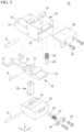
FIG. 3 is a perspective view showing a die, a punch, and pusher applied to a notching apparatus for an electrode substrate of a rechargeable battery ofFIG. 1 .FIG. 4 is a perspective view of a pusher applied toFIG. 1 andFIG. 3 .FIG. 5 is an exploded perspective view of a pusher shown inFIG. 4 .FIG. 6 a top plan view showing a state in which a blade of a pusher ofFIG. 4 is disposed in a die and a scrap ofFIG. 3 . Referring toFIG. 3 to FIG. 6 , thepusher 400 may include anupper block 430 and alower block 440. - The
upper block 430 mounts theblade 410 at an operation center by a first hinge H1, and is configured to elastically support asecond end 412 of theblade 410 positioned at a second side of the operation center in downward direction, such that thefirst end 411 of theblade 410 positioned at a first side of the operation center may be operated in a vertical direction. - The
lower block 440 is provided at a lower side of theupper block 430, and configured to mount, at a lower end, ahook 450 coupled to or released from thefirst end 411 at the operation center of theblade 410 by a second hinge H2 and to elastically support thehook 450 from the exterior side to the interior side in the second direction (the y-axis direction). - More specifically, the
upper block 430 may include afirst height portion 431 and asecond height portion 432. Thefirst height portion 431 is formed at a low height in the interior side in the second direction (the y-axis direction). Thesecond height portion 432 is formed in the exterior side in the second direction, at a height higher than that of thefirst height portion 431. - The
upper block 430 has a first through-hole 433 penetrating in the vertical direction at the boundary between thefirst height portion 431 and thesecond height portion 432, and installs the operating center of theblade 410 located at the first through-hole 433 by the first hinge H1. Accordingly, at the lower side of theupper block 430, theblade 410 forms thefirst end 411 in the interior side in the second direction (the y-axis direction), and forms thesecond end 412 in in the exterior side, having the first hinge H1 as the operation center. -
FIG. 7 is a cross-sectional view according to line VII-VII ofFIG. 6 , and shows operation states of a punch and an upper block at the time of immediately before descending for the notching, during descending, during ascending after the notching, and after completing the ascending. Referring toFIG. 3 to FIG. 7 , thesecond height portion 432 may include a firstelastic member 434 in the vertical direction. - As an example, the first
elastic member 434 is embedded in thesecond height portion 432 interposing afirst push member 435 and supported by acover 436. Thecover 436 is coupled to aprotrusion 437 formed at an upper end of thesecond height portion 432 through a first side, and fixed to thesecond height portion 432 by abolt 438 through a second side, thereby facilitating embedding of the firstelastic member 434 and thefirst push member 435. - The
second end 412 of theblade 410 may be provided at a lower side of thesecond height portion 432, and may receive a downward elastic force of the firstelastic member 434 and thefirst push member 435. Accordingly, thefirst end 411 of theblade 410 may be disposed at a lower side of thefirst height portion 431, and may receive a downward force of thepunch 20. The downward force of thepunch 20 overcomes the elastic force of the firstelastic member 434 and lowers thefirst end 411 of theblade 410 having the first hinge H1 as the operation center, and therefore, presses and separates the notching scrap SCR from the electrode substrate S and the electrode E. - The
lower block 440 is provided at a lower side of thesecond height portion 432 and a lower side of the boundary, may be provided with a second through-hole 443 penetrated in the vertical direction, and may install a lower end of thehook 450 positioned in the second through-hole 443 by the second hinge H2. Accordingly, thehook 450 operates having the second hinge H2 as its operation center. - The
blade 410 may be provided with a hook pin H3 in thefirst height portion 431. Thelower block 440 may embed a secondelastic member 444 in the second direction. As an example, the secondelastic member 444 is embedded in thelower block 440 interposing thesecond push member 445, and fixed with aplate 448 andbolts 438. - The
hook 450 receives the elastic force of the secondelastic member 444 and thesecond push member 445 to be coupled to the hook pin H3 when theblade 410 descends. When theblade 410 rises, thehook 450 is coupled to the hook pin H3 while receiving an elastic force, and then released by the rise of the hook pin H3. - As an example, the hook pin H3 may be formed as a curved surface centered on the first direction (the x-axis direction). The
hook 450 protrudes toward the curved surface of the hook pin H3 and has an upperinclined surface 452 and a lowerinclined surface 451 facing the hook pin H3. - The upper
inclined surface 452 softens the engagement with the hook pin H3 to reduce coupling shock when theblade 410 descends, and the lowerinclined surface 451 softens the disengagement with the hook pin H3 to reduce the release shock when theblade 410 ascends. - The
blade 410 may be provided with a third through-hole 413 above the second through-hole 443 such that thehook 450 is inserted in the vertical direction (z-axis direction). The hook pin H3 may be installed by extending from the third through-hole 413 in the first direction. Theblade 410 may be provided with aconnection portion 414 connecting thefirst end 411 and the third through-hole 413, and theconnection portion 414 may be located in therecesses 11 and 12 (refer toFIG. 6 andFIG. 7 ). -
FIG. 8 shows an operation state in which hook pin has rotated a hook around a second hinge as a punch and an upper block further descends for the notching from the state ofFIG. 7 . Referring toFIG. 7 andFIG. 8 , the notching apparatus notches the electrode substrate S to the electrode E while thepunch 20 and the die 10 ascend and descend in opposite directions. -
FIG. 7 is a cross-sectional view according to line VII-VII ofFIG. 6 , and shows operation states of a punch and an upper block at the time of immediately before descending for the notching, during descending, during ascending after the notching, and after completing the ascending. It illustrates a state just before descending for notching, and in this state, thepunch 20 and theupper block 430 are located at the highest level. - Immediately before the
punch 20 and theupper block 430 descend for notching, in theupper block 430 of thepusher 400, thesecond end 412 of theblade 410 receives a downward elastic support force by the firstelastic member 434 and thefirst push member 435, and accordingly, thefirst end 411 rotates around the first hinge H1 as the operation center to be accommodated the receivingrecess 21 of thepunch 20. At this time, theconnection portion 414 may be located in therecess 12. - In the
lower block 440 of thepusher 400, thehook 450 receives an elastic support force inward in the second direction (the y-axis direction) by the secondelastic member 444 and thesecond push member 445. Accordingly, thehook 450 rotates around the second hinge H2 and maintains a state of maximum turning inward in the second direction (the y-axis direction) (state inFIG. 7 ). - Referring to
FIG. 7 andFIG. 8 , thepunch 20 and theupper block 430 are equally descending from the state ofFIG. 7 to the state ofFIG. 8 . While descending as shown inFIG. 7 , thepunch 20 and theupper block 430 have additionally descended to the state ofFIG. 8 for notching. Accordingly, thepunch 20 and theupper block 430 further approach to the die 10 and thelower block 440, and theblade 410 further approaches to the electrode substrate S and thehook 450. - At this time, the hook pin H3 pushes the
hook 450 to rotate around the second hinge H2. As a result, thehook 450 rotates around the second hinge H2, and maintains the maximum turning state outward in the second direction (the y-axis direction) (state inFIG. 8 ). Thehook 450 is elastically supported by the elastic force of the secondelastic member 444. -
FIG. 9 shows states during the notching and after completing the notching as the punch and the upper block further descends from the state ofFIG. 8 and a punch further descends than the upper block. - Referring to
FIG. 8 andFIG. 9 , thepunch 20 and theupper block 430 descend differently from the state ofFIG. 8 to the state ofFIG. 9 . That is, the descending amount of thepunch 20 is greater than the descending amount of theupper block 430. Therefore, from a state in which theupper block 430 is in contact with thelower block 440, thepunch 20 may further descend into thedie 10. - As the
punch 20 descends, in theupper block 430, thefirst end 411 of theblade 410 is pressed to descend, and thus the scrap SCR may be separated from the electrode E notched from the electrode substrate S. At this time, theconnection portion 414 is located in therecesses second end 412 of theblade 410 moves upward while overcoming the firstelastic member 434 and thefirst push member 435. - In the
lower block 440 of thepusher 400, thehook 450 is rotated around the second hinge H2 by the secondelastic member 444 and thesecond push member 445, and thereby rotates inward in the second direction (the y-axis direction) to be caught by an upper surface of the hook pin H3. - To the contrary, referring to
FIG. 9 andFIG. 8 , thepunch 20 and theupper block 430 ascend differently from the state ofFIG. 9 to the state ofFIG. 8 . That is, the ascending amount of thepunch 20 is greater than the ascending amount of theupper block 430. Therefore, from a state in which theupper block 430 is separated from thelower block 440, thepunch 20 further ascends out of thedie 10. - At this time, in the
upper block 430, thesecond end 412 of theblade 410 is in a state pressed by the ascending of thepunch 20, and accordingly, thefirst end 411 ascends. At this time, theconnection portion 414 is located on therecess 12, and thesecond end 412 of theblade 410 is elastically supported by the firstelastic member 434 and thefirst push member 435. - In the
lower block 440 of thepusher 400, thehook 450 is elastically supported by the secondelastic member 444 and thesecond push member 445 while being pushed outward in the second direction by the hook pin H3 (refer toFIG. 8 ). - In addition, referring to
FIG. 8 andFIG. 7 , thepunch 20 and theupper block 430 equally ascend from the state ofFIG. 8 to the state ofFIG. 7 . Therefore, thepunch 20 and theupper block 430 become spaced apart from thedie 10 and thelower block 440, and theblade 410 becomes spaced apart from the electrode substrate S and thehook 450. At this time, thehook 450 receiving the elastic force by the secondelastic member 444 and thesecond push member 445 rotates back around the second hinge H2 while being disengaged from the hook pin H3. This completes one notching process. - A notching apparatus of an embodiment may repetitively perform the operation from the state of
FIG. 7 to the state ofFIG. 8 , the operation from the state ofFIG. 8 to the state ofFIG. 9 , and their reversal operations, and thereby manufacture the electrode E by notching the electrode substrate S that is continuously supplied, while smoothly discharging the generated scrap SCR. - While this disclosure has been described in connection with what is presently considered to be practical embodiments, it is to be understood that the disclosure is not limited to the disclosed embodiments, but, on the contrary, is intended to cover various modifications and equivalent arrangements included within the scope of the appended claims.
-
10: die 11, 12: recess 21: receiving recess 20: punch 100: lower plate assembly 110: first die 120: first punch 200: upper plate assembly 210: second die 220: second punch 300: lifting member 400: pusher 410: blade 411: first end 412: second end 413: third through-hole 414: connection portion 430: upper block 431: first height portion 432: second height portion 433: first through-hole 434: first elastic member 435: first push member 436: cover 437: protrusion 438: bolt 440: lower block 443: second through-hole 444: second elastic member 445: second push member 448: plate 450: hook 451: lower inclined surface 452: upper inclined surface CP: coated portion E: electrode H1: first hinge H2: second hinge H3: hook pin S: electrode substrate SCR: scrap T: tab UCP: uncoated portion
Claims (11)
- A notching apparatus for an electrode substrate of a rechargeable battery, the notching apparatus comprising:a lower plate assembly provided with a die;an upper plate assembly provided with a punch facing toward the die, wherein the upper plate has a width in a second direction crossing a first direction; anda pusher provided to a first side of the punch and the die in the second direction, and configured to notch the electrode from the electrode substrate and separate a generated scrap by pressing with a blade,wherein the blade is disposed to connect an exterior and an interior of the die in the second direction, andwherein at least a first side of the punch and the die is provided with a recess on which the blade may be laid.
- The notching apparatus of claim 1, wherein the punch is provided with a receiving recess configured to accommodate a first end of the blade at a lower surface.
- The notching apparatus of claim 2, wherein the first end of the blade forms three branch structures corresponding to an uncoated portion at an outside or an opposite side of a tab of the electrode.
- The notching apparatus of any one of claims 1 to 3, wherein the pusher comprises:an upper block configured to mount the blade at an operation center by a first hinge, and to elastically support a second end of the blade located at a second side of the operation center in a downward direction to vertically operate the first end of the blade located at a first side of the operation center; anda lower block provided at a lower side of the upper block, and configured to mount a hook coupled to or released from the first end at the operation center by a second hinge and to elastically support the hook from an exterior side to an interior side in the second direction.
- The notching apparatus of claim 4, wherein:the upper block comprises a first height portion formed at a low height in the interior side in the second direction and a second height portion formed at a higher height than the first height portion in the exterior side in the second direction, andconfigured to install the operation center of the blade located in a first through-hole vertically penetrating a boundary of the first height portion and the second height portion by the first hinge.
- The notching apparatus of claim 5, wherein:the second height portion is provided with a first elastic member in the vertical direction;the second end of the blade is provided at a lower side of the second height portion to receive an elastic force of the first elastic member; andthe first end of the blade is disposed at a lower side of the first height portion to receive a downward force of the punch.
- The notching apparatus of claim 5 or claim 6, wherein the lower block is configured to install a lower end of the hook at a second through-hole provided at and vertically penetrating a lower side of the second height portion and a lower side of the boundary.
- The notching apparatus of any one of claims 5 to 7, wherein:the blade is provided with a hook pin in the first height portion;the lower block is provided with a second elastic member in the second direction; andthe hook receives an elastic force of the second elastic member coupled to the hook pin as the blade descends and is disengaged from the hook pin when the blade ascends.
- The notching apparatus of claim 8, wherein:the hook pin is formed as a curved surface centered on the first direction;
andthe hook protrudes toward the curved surface, and has an upper inclined surface and a lower inclined surface facing the hook pin. - The notching apparatus of claim 8 or claim 9, wherein:the blade is provided with a third through-hole at an upper side of a second through-hole such that the hook is inserted in the vertical direction; andthe hook pin is installed in the third through-hole in the first direction.
- The notching apparatus of claim 10, wherein:the blade is provided with a connection portion configured to connect the first end and the third through-hole; andthe connection portion is positioned in the recess.
Applications Claiming Priority (1)
| Application Number | Priority Date | Filing Date | Title |
|---|---|---|---|
| KR1020220080905A KR20240002825A (en) | 2022-06-30 | 2022-06-30 | Notching device for rechargeable battery electrode substrate |
Publications (2)
| Publication Number | Publication Date |
|---|---|
| EP4299205A1 true EP4299205A1 (en) | 2024-01-03 |
| EP4299205B1 EP4299205B1 (en) | 2025-12-24 |
Family
ID=87060405
Family Applications (1)
| Application Number | Title | Priority Date | Filing Date |
|---|---|---|---|
| EP23182725.4A Active EP4299205B1 (en) | 2022-06-30 | 2023-06-30 | Notching apparatus for electrode substrate of rechargeable battery |
Country Status (4)
| Country | Link |
|---|---|
| US (1) | US20240001580A1 (en) |
| EP (1) | EP4299205B1 (en) |
| KR (1) | KR20240002825A (en) |
| CN (1) | CN117324500A (en) |
Cited By (2)
| Publication number | Priority date | Publication date | Assignee | Title |
|---|---|---|---|---|
| EP4541537A1 (en) * | 2023-10-19 | 2025-04-23 | Samsung SDI Co., Ltd. | Notching apparatus for secondary battery |
| EP4574365A1 (en) * | 2023-12-22 | 2025-06-25 | Samsung Sdi Co., Ltd. | Electrode plate notching apparatus and electrode plate notching method using the same |
Citations (5)
| Publication number | Priority date | Publication date | Assignee | Title |
|---|---|---|---|---|
| DE4106068A1 (en) * | 1990-03-12 | 1991-10-02 | Meurer Nonfood Product Gmbh | Scrap removing mechanism from cardboard blank |
| WO2010082372A1 (en) * | 2009-01-19 | 2010-07-22 | 日本ダイスチール株式会社 | Punching debris receiving device and stripping device |
| KR20190112379A (en) * | 2018-03-26 | 2019-10-07 | 주식회사 유진테크놀로지 | Notching mold having a folding prevention device of tab |
| KR20220059398A (en) * | 2020-11-02 | 2022-05-10 | 주식회사 엘지에너지솔루션 | Battery Lead Cutting Device Equipped With A Blocking Part And Battery Lead cutting method using It |
| KR102495105B1 (en) * | 2022-11-04 | 2023-02-06 | 안혁 | Punching mold with scrap suction function |
Family Cites Families (11)
| Publication number | Priority date | Publication date | Assignee | Title |
|---|---|---|---|---|
| US557142A (en) * | 1896-03-31 | Dayid mcgill | ||
| US2624940A (en) * | 1949-02-11 | 1953-01-13 | Le Roy M Osborne | Card punch |
| US6832535B1 (en) * | 2000-09-25 | 2004-12-21 | Rockford Manufacturing Group | Air ejection and compliant gage pin for rod cutting machines |
| EP1758697B1 (en) * | 2004-06-02 | 2012-01-25 | Stefan Fellenberg | Method and press for cutting high-strength sheet metal |
| KR20120034397A (en) * | 2010-10-01 | 2012-04-12 | 삼성전자주식회사 | Apparatus for discharging scrap of pressing mold |
| KR101550023B1 (en) * | 2015-03-03 | 2015-09-08 | 주식회사전우정밀 | Press mold apparatus |
| KR101853050B1 (en) * | 2017-02-24 | 2018-04-27 | 주식회사 엠플러스 | Notching machine mold scrap shutter assembly |
| JP2020097110A (en) * | 2020-02-25 | 2020-06-25 | 大創株式会社 | Punching scrap removal female mold |
| JP2022089693A (en) * | 2020-12-04 | 2022-06-16 | 株式会社 小池製作所 | Punching scrap receiver and stripping method using the same |
| CN113145719A (en) * | 2021-04-25 | 2021-07-23 | 广州中益机械有限公司 | High-precision high-efficiency automatic feeding mechanism |
| KR102392988B1 (en) * | 2021-11-12 | 2022-04-29 | 서덕기 | The notching mold for secondary batteries that can be automatically ejected |
-
2022
- 2022-06-30 KR KR1020220080905A patent/KR20240002825A/en active Pending
-
2023
- 2023-06-27 US US18/215,086 patent/US20240001580A1/en active Pending
- 2023-06-29 CN CN202310787445.8A patent/CN117324500A/en active Pending
- 2023-06-30 EP EP23182725.4A patent/EP4299205B1/en active Active
Patent Citations (5)
| Publication number | Priority date | Publication date | Assignee | Title |
|---|---|---|---|---|
| DE4106068A1 (en) * | 1990-03-12 | 1991-10-02 | Meurer Nonfood Product Gmbh | Scrap removing mechanism from cardboard blank |
| WO2010082372A1 (en) * | 2009-01-19 | 2010-07-22 | 日本ダイスチール株式会社 | Punching debris receiving device and stripping device |
| KR20190112379A (en) * | 2018-03-26 | 2019-10-07 | 주식회사 유진테크놀로지 | Notching mold having a folding prevention device of tab |
| KR20220059398A (en) * | 2020-11-02 | 2022-05-10 | 주식회사 엘지에너지솔루션 | Battery Lead Cutting Device Equipped With A Blocking Part And Battery Lead cutting method using It |
| KR102495105B1 (en) * | 2022-11-04 | 2023-02-06 | 안혁 | Punching mold with scrap suction function |
Cited By (2)
| Publication number | Priority date | Publication date | Assignee | Title |
|---|---|---|---|---|
| EP4541537A1 (en) * | 2023-10-19 | 2025-04-23 | Samsung SDI Co., Ltd. | Notching apparatus for secondary battery |
| EP4574365A1 (en) * | 2023-12-22 | 2025-06-25 | Samsung Sdi Co., Ltd. | Electrode plate notching apparatus and electrode plate notching method using the same |
Also Published As
| Publication number | Publication date |
|---|---|
| EP4299205B1 (en) | 2025-12-24 |
| KR20240002825A (en) | 2024-01-08 |
| CN117324500A (en) | 2024-01-02 |
| US20240001580A1 (en) | 2024-01-04 |
Similar Documents
| Publication | Publication Date | Title |
|---|---|---|
| EP4299205A1 (en) | Notching apparatus for electrode substrate of rechargeable battery | |
| KR101813249B1 (en) | Apparatus for cutting jelly roll tab of lithium secondary battery | |
| EP3605646B1 (en) | Battery pack having bottom connection type tray and method of manufacturing the same. | |
| KR101731146B1 (en) | Forming method of connect portion of plural electrode tab and electrode lead of electrode assembly and secondary battery using the same | |
| KR102951291B1 (en) | Battery module having a simple connection structure between cell lead and voltage sensing member and battery pack including the same | |
| JP2019502244A (en) | Battery module strap, battery module including the strap, and strap crimping jig | |
| KR20140036438A (en) | Carrier for secondary battery | |
| US12491588B2 (en) | Welding positioning apparatus, battery production line, and welding method | |
| EP3723162A1 (en) | Auto-pressing jig apparatus for pressing electrode lead to busbar | |
| EP4432455A1 (en) | Electrode tab welding apparatus, electrode tab welding method, and secondary battery | |
| CN116190745A (en) | Cell processing equipment, cell processing method, and battery production line | |
| KR102670131B1 (en) | Cutting device for electrode sheet | |
| CN109997243B (en) | Manufacturing equipment for various types of cap assemblies | |
| KR20200069883A (en) | Apparatus for stacking of system for producing electrodes of battery and method for stacking producing electrodes of battery | |
| US20240170711A1 (en) | Cell processing equipment, cell processing method, and battery production line | |
| US12444814B2 (en) | Apparatus for welding electrode tabs, method for welding electrode tabs, and secondary battery | |
| KR102614097B1 (en) | stage module for manufacturing electrode assembly and carrier for transporting electrode assembly and electrode assembly manufacturing method | |
| JP7536180B2 (en) | Cell installation jig, cell alignment device, and cell installation method for preventing damage to the appearance of battery cells | |
| KR102942904B1 (en) | Mold for Preventing Tab Sagging | |
| KR102834586B1 (en) | Bus bar assembly and method for manufacturing thereof | |
| CN221239654U (en) | Battery cover plate press-fitting tool | |
| KR20200069886A (en) | Algin apparatus of system for producing electrodes of battery | |
| KR102843938B1 (en) | Apparatus for manufacturing secondary battery pack with the guide block | |
| EP4431407A1 (en) | Separation plate, tray assembly, and battery processing device | |
| KR102203400B1 (en) | The jig for battery cell attached |
Legal Events
| Date | Code | Title | Description |
|---|---|---|---|
| PUAI | Public reference made under article 153(3) epc to a published international application that has entered the european phase |
Free format text: ORIGINAL CODE: 0009012 |
|
| STAA | Information on the status of an ep patent application or granted ep patent |
Free format text: STATUS: REQUEST FOR EXAMINATION WAS MADE |
|
| 17P | Request for examination filed |
Effective date: 20230630 |
|
| AK | Designated contracting states |
Kind code of ref document: A1 Designated state(s): AL AT BE BG CH CY CZ DE DK EE ES FI FR GB GR HR HU IE IS IT LI LT LU LV MC ME MK MT NL NO PL PT RO RS SE SI SK SM TR |
|
| GRAP | Despatch of communication of intention to grant a patent |
Free format text: ORIGINAL CODE: EPIDOSNIGR1 |
|
| STAA | Information on the status of an ep patent application or granted ep patent |
Free format text: STATUS: GRANT OF PATENT IS INTENDED |
|
| RIC1 | Information provided on ipc code assigned before grant |
Ipc: B21D 45/00 20060101AFI20250716BHEP Ipc: B21D 45/04 20060101ALI20250716BHEP Ipc: B26D 7/18 20060101ALI20250716BHEP Ipc: B26F 1/40 20060101ALI20250716BHEP Ipc: B21D 45/06 20060101ALI20250716BHEP |
|
| INTG | Intention to grant announced |
Effective date: 20250724 |
|
| GRAS | Grant fee paid |
Free format text: ORIGINAL CODE: EPIDOSNIGR3 |
|
| GRAA | (expected) grant |
Free format text: ORIGINAL CODE: 0009210 |
|
| STAA | Information on the status of an ep patent application or granted ep patent |
Free format text: STATUS: THE PATENT HAS BEEN GRANTED |
|
| AK | Designated contracting states |
Kind code of ref document: B1 Designated state(s): AL AT BE BG CH CY CZ DE DK EE ES FI FR GB GR HR HU IE IS IT LI LT LU LV MC ME MK MT NL NO PL PT RO RS SE SI SK SM TR |
|
| REG | Reference to a national code |
Ref country code: CH Ref legal event code: F10 Free format text: ST27 STATUS EVENT CODE: U-0-0-F10-F00 (AS PROVIDED BY THE NATIONAL OFFICE) Effective date: 20251224 Ref country code: GB Ref legal event code: FG4D |
|
| REG | Reference to a national code |
Ref country code: DE Ref legal event code: R096 Ref document number: 602023010011 Country of ref document: DE |
|
| REG | Reference to a national code |
Ref country code: LT Ref legal event code: MG9D |
|
| PG25 | Lapsed in a contracting state [announced via postgrant information from national office to epo] |
Ref country code: NO Free format text: LAPSE BECAUSE OF FAILURE TO SUBMIT A TRANSLATION OF THE DESCRIPTION OR TO PAY THE FEE WITHIN THE PRESCRIBED TIME-LIMIT Effective date: 20260324 |
|
| PG25 | Lapsed in a contracting state [announced via postgrant information from national office to epo] |
Ref country code: FI Free format text: LAPSE BECAUSE OF FAILURE TO SUBMIT A TRANSLATION OF THE DESCRIPTION OR TO PAY THE FEE WITHIN THE PRESCRIBED TIME-LIMIT Effective date: 20251224 Ref country code: HR Free format text: LAPSE BECAUSE OF FAILURE TO SUBMIT A TRANSLATION OF THE DESCRIPTION OR TO PAY THE FEE WITHIN THE PRESCRIBED TIME-LIMIT Effective date: 20251224 |
|
| PG25 | Lapsed in a contracting state [announced via postgrant information from national office to epo] |
Ref country code: RS Free format text: LAPSE BECAUSE OF FAILURE TO SUBMIT A TRANSLATION OF THE DESCRIPTION OR TO PAY THE FEE WITHIN THE PRESCRIBED TIME-LIMIT Effective date: 20260324 |
|
| PG25 | Lapsed in a contracting state [announced via postgrant information from national office to epo] |
Ref country code: LV Free format text: LAPSE BECAUSE OF FAILURE TO SUBMIT A TRANSLATION OF THE DESCRIPTION OR TO PAY THE FEE WITHIN THE PRESCRIBED TIME-LIMIT Effective date: 20251224 |