EP4299195A1 - Coating mechanism and coating apparatus - Google Patents
Coating mechanism and coating apparatus Download PDFInfo
- Publication number
- EP4299195A1 EP4299195A1 EP22759724.2A EP22759724A EP4299195A1 EP 4299195 A1 EP4299195 A1 EP 4299195A1 EP 22759724 A EP22759724 A EP 22759724A EP 4299195 A1 EP4299195 A1 EP 4299195A1
- Authority
- EP
- European Patent Office
- Prior art keywords
- application
- application needle
- needle holder
- fixing unit
- magnet
- Prior art date
- Legal status (The legal status is an assumption and is not a legal conclusion. Google has not performed a legal analysis and makes no representation as to the accuracy of the status listed.)
- Granted
Links
Images





Classifications
-
- B—PERFORMING OPERATIONS; TRANSPORTING
- B05—SPRAYING OR ATOMISING IN GENERAL; APPLYING FLUENT MATERIALS TO SURFACES, IN GENERAL
- B05C—APPARATUS FOR APPLYING FLUENT MATERIALS TO SURFACES, IN GENERAL
- B05C1/00—Apparatus in which liquid or other fluent material is applied to the surface of the work by contact with a member carrying the liquid or other fluent material, e.g. a porous member loaded with a liquid to be applied as a coating
- B05C1/02—Apparatus in which liquid or other fluent material is applied to the surface of the work by contact with a member carrying the liquid or other fluent material, e.g. a porous member loaded with a liquid to be applied as a coating for applying liquid or other fluent material to separate articles
- B05C1/025—Apparatus in which liquid or other fluent material is applied to the surface of the work by contact with a member carrying the liquid or other fluent material, e.g. a porous member loaded with a liquid to be applied as a coating for applying liquid or other fluent material to separate articles to flat rectangular articles, e.g. flat sheets
-
- B—PERFORMING OPERATIONS; TRANSPORTING
- B05—SPRAYING OR ATOMISING IN GENERAL; APPLYING FLUENT MATERIALS TO SURFACES, IN GENERAL
- B05C—APPARATUS FOR APPLYING FLUENT MATERIALS TO SURFACES, IN GENERAL
- B05C1/00—Apparatus in which liquid or other fluent material is applied to the surface of the work by contact with a member carrying the liquid or other fluent material, e.g. a porous member loaded with a liquid to be applied as a coating
- B05C1/02—Apparatus in which liquid or other fluent material is applied to the surface of the work by contact with a member carrying the liquid or other fluent material, e.g. a porous member loaded with a liquid to be applied as a coating for applying liquid or other fluent material to separate articles
Definitions
- the present invention relates to an application apparatus and an application mechanism.
- An application mechanism described in Japanese Patent Laying-Open No. 2018-20325 has an application needle holder fixing unit, an application needle holder, and an application needle.
- the application needle holder is attached to the application needle holder fixing unit.
- the application needle is held at the application needle holder.
- the application mechanism described in PTL 1 does not have a mechanism for cushioning an impact when the application needle is brought into contact with an application surface.
- an application mechanism described in Japanese Patent Laying-Open No. 2015-112577 has an application needle holder, an application needle fixing plate, and an application needle.
- the application needle holder is attached to a movable base.
- the application needle is held at the application needle fixing plate.
- the application needle holder accommodates a spring and a linear guide.
- the linear guide holds the application needle so as to be slidable in a direction orthogonal to the application surface.
- the spring biases the application needle toward the application surface.
- the application mechanism described in PTL 2 When the application mechanism described in PTL 2 is applied to a purpose of use that requires strict management for contamination such as a diagnosis tip for extracorporeal diagnosis of diseases, it may be required to configure the application needle holder and the application needle to be disposable or sterilize the application needle holder and the application needle.
- the present invention has been made in view of the above-described problem of the conventional art. More specifically, the present invention provides an application mechanism and an application apparatus, by each of which an impact when an application needle is brought into contact with an application surface can be cushioned without increasing manufacturing cost even when an application needle holder and the application needle need to be disposable or the application needle holder and the application needle need to be sterilized.
- An application mechanism of the present invention applies a liquid material on an application surface.
- the application mechanism includes: an application needle holder fixing unit; an application needle holder detachably attached to the application needle holder fixing unit; an application needle held at the application needle holder; and a cushioning mechanism.
- the cushioning mechanism is capable of cushioning an impact when the application needle is brought into contact with the application surface.
- the application mechanism may have a linear guide and an elastic member.
- the application needle holder fixing unit may be held at the linear guide so as to be slidable in a direction orthogonal to the application surface.
- the elastic member may bias the application needle holder fixing unit toward the application surface.
- the application mechanism may further include: a first magnet held at the application needle holder fixing unit; and a second magnet held at the application needle holder.
- the application needle holder may be composed of a resin material.
- the application needle holder may be detachably attached to the application needle holder fixing unit by the second magnet being attracted to the first magnet.
- the application mechanism may further include: a first magnet attached to the application needle holder fixing unit; and a second magnet held at the application needle holder.
- the application needle holder may be composed of a non-magnetic metal material.
- the application needle holder may be detachably attached to the application needle holder fixing unit by the second magnet being attracted to the first magnet.
- An application mechanism of the present invention includes the above-described application mechanism.
- an impact when the application needle is brought into contact with the application surface can be cushioned without increasing manufacturing cost even when the application needle holder and the application needle need to be disposable or the application needle holder and the application needle need to be sterilized.
- application mechanism 10 An application mechanism (hereinafter referred to as "application mechanism 10") according to a first embodiment will be described.
- Fig. 1 is a perspective view of application mechanism 10 with an application needle holder 12, an application needle 13, and a container 15 being not illustrated.
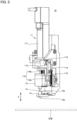
- Fig. 2 is a side view of application mechanism 10 with application needle holder 12, application needle 13, and container 15 being not illustrated. As shown in Figs. 1 and 2 , application mechanism 10 has a driving mechanism 11.
- Driving mechanism 11 has, for example, a servo motor 111, a cam 112, a bearing 113, a cam coupling plate 114, a movable portion 115, a cushioning mechanism 116, an application needle holder fixing unit 117, and a first magnet 118.
- Servo motor 111 has a rotation shaft 111a.
- Rotation shaft 111a extends along a Z axis. The Z axis is orthogonal to an application surface of a substrate SUB.
- servo motor 111 is connected to an electrical-component box 27 described later.
- Servo motor 111 rotates rotation shaft 111a around a center axis.
- Cam 112 has a first surface 112a and a second surface 112b. First surface 112a faces downward. Second surface 112b faces upward. That is, second surface 112b is a surface opposite to first surface 112a.
- Second surface 112b has a central portion and an outer peripheral portion. The outer peripheral portion of second surface 112b is located around the central portion of second surface 112b. Cam 112 is attached to rotation shaft 111a at the central portion of second surface 112b. A distance between second surface 112b and first surface 112a is varied along a peripheral direction (a direction along a circumference centered on the center axis of rotation shaft 111a). Second surface 112b is a cam surface of cam 112.
- Bearing 113 is disposed such that the outer peripheral surface of bearing 113 is in contact with the cam surface (second surface 112b) of cam 112.
- Cam coupling plate 114 is coupled to bearing 113 at one end and is coupled to movable portion 115 at the other end.
- Cushioning mechanism 116 is attached to movable portion 115.
- Cushioning mechanism 116 has, for example, a linear guide 116a and an elastic member 116b.
- Linear guide 116a is attached to movable portion 115.
- Application needle holder fixing unit 117 is held by linear guide 116a so as to be slidable in the Z axis direction.
- Elastic member 116b is, for example, a coil spring. Elastic member 116b biases application needle holder fixing unit 117 toward the application surface of substrate SUB. More specifically, elastic member 116b presses application needle holder fixing unit 117 against a stopper 115a provided at movable portion 115. First magnet 118 is held at application needle holder fixing unit 117.
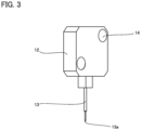
- Fig. 3 is a perspective view of application needle holder 12 and application needle 13 included in application mechanism 10.
- Fig. 4 is a side view of application needle holder 12 and application needle 13 included in application mechanism 10.
- application mechanism 10 further has application needle holder 12 and application needle 13.
- Application needle 13 has a distal end 13a and a proximal end 13b.
- Proximal end 13b is an end opposite to distal end 13a in a longitudinal direction of application needle 13.
- the longitudinal direction of application needle 13 is along the Z axis direction.
- Application needle 13 is held by application needle holder 12. More specifically, application needle 13 is held at application needle holder 12 with the proximal end 13b side of application needle 13 being embedded in application needle holder 12. Application mechanism 10 further has a second magnet 14.
- Application needle holder 12 is composed of a resin material.
- Application needle 13 and second magnet 14 are held at application needle holder 12 with application needle 13 and second magnet 14 being insert-molded together with the resin material of application needle holder 12, for example. That is, application needle holder 12 does not have: a linear guide that holds application needle 13 so as to be slidable in the Z axis direction; and an elastic member that biases application needle 13 toward the application surface of substrate SUB.
- FIG. 5 is a perspective view of application mechanism 10. As shown in Fig. 5 , application needle holder 12 is detachably attached to application needle holder fixing unit 117. More specifically, application needle holder 12 is detachably attached to application needle holder fixing unit 117 by second magnet 14 being attracted to first magnet 118.
- Application mechanism 10 further has a container 15.
- Container 15 has an upper end 15a and a lower end 15b.
- Lower end 15b is an end opposite to upper end 15a.
- Container 15 is hollow.
- Container 15 is opened at upper end 15a.
- Lower end 15b is closed by a bottom wall provided with a through hole.
- a liquid material is stored in an inner space of container 15.
- Distal end 13a is inserted into the inner space of container 15 from the opening of upper end 15a.
- cam 112 As rotation shaft 111a is rotated, cam 112 is rotated. Since the distance between second surface 112b and first surface 112a is varied, the rotation of cam 112 varies the position of bearing 113 in the Z axis direction.
- movable portion 115 is coupled to bearing 113 by cam coupling plate 114, and application needle holder fixing unit 117 is attached to movable portion 115. Further, application needle holder 12 is attached to application needle holder fixing unit 117. Therefore, when the position of bearing 113 in the Z axis direction is varied, the position of application needle 13 held by application needle holder 12 in the Z axis direction is varied. In this way, driving mechanism 11 moves the position of application needle 13 (distal end 13a) in the Z axis direction.
- driving mechanism 11 moves application needle 13 to protrude distal end 13a from the through hole formed in the bottom wall that closes lower end 15b of container 15, the liquid material in container 15 is adhered to distal end 13a.
- application needle holder fixing unit 117 is held by linear guide 116a so as to be slidable in the Z axis direction and elastic member 116b biases application needle holder fixing unit 117 toward the application surface of substrate SUB, application needle 13 is moved away from the application surface of substrate SUB along the Z axis direction when application needle 13 is brought into contact with the application surface of substrate SUB, thereby cushioning the impact when application needle 13 is brought into contact with the application surface of substrate SUB.
- application needle holder 12 is composed of the resin material and does not have a linear guide and an elastic member that cushion an impact when application needle 13 is brought into contact with the application surface of substrate SUB, an increase in manufacturing cost can be suppressed even when application needle holder 12 and application needle 13 are configured to be disposable.
- application mechanism 10A An application mechanism (hereinafter referred to as "application mechanism 10A") according to a second embodiment will be described.
- application mechanism 10 differs from application mechanism 10 will be mainly described, and the same explanation will not be described repeatedly.
- Application mechanism 10A has a driving mechanism 11, an application needle holder 12, an application needle 13, a second magnet 14, and a container 15.
- application mechanism 10A is the same as application mechanism 10.
- application mechanism 10A differs from application mechanism 10 in terms of a detailed configuration of application needle holder 12.
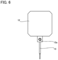
- Fig. 6 is a front view of application needle holder 12 and application needle 13 included in application mechanism 10A.
- application needle 13 is held by application needle holder 12 on the proximal end 13b side. More specifically, application needle 13 is held at application needle holder 12 by a screw 12a.
- Application needle holder 12 is composed of a non-magnetic metal material. A specific example of the non-magnetic metal material is aluminum or an aluminum alloy.
- Fig. 7 is a rear view of application needle holder 12 and application needle 13 included in application mechanism 10A.
- Fig. 8 is a side view of application needle holder 12 and application needle 13 included in application mechanism 10A.
- second magnet 14 is held at application needle holder 12. More specifically, second magnet 14 is held at application needle holder 12 by a screw 12b.
- application needle holder 12 does not have: a linear guide that holds application needle 13 so as to be slidable in the Z axis direction; and an elastic member that biases application needle 13 toward the application surface of substrate SUB.
- application mechanism 10A has cushioning mechanism 116 as with application mechanism 10, an impact when application needle 13 is brought into contact with the application surface of substrate SUB can be cushioned.
- application needle holder 12 and application needle 13 In order to sterilize application needle holder 12 and application needle 13, application needle holder 12 and application needle 13 needs to be held under a high-temperature environment.
- application needle holder 12 In application mechanism 10A, since application needle 13 is fixed by screw 12a, application needle holder 12 has no portion adhered by an adhesive agent. Further, in application mechanism 10A, application needle holder 12 is composed of a metal material having a heat resistance. Therefore, in application mechanism 10A, since application needle holder 12 and application needle 13 can be sterilized under the high-temperature environment and therefore can be reused, an increase in manufacturing cost can be suppressed.
- application apparatus 100 An application apparatus (hereinafter referred to as "application apparatus 100") according to a third embodiment will be described.
- Fig. 9 is a perspective view of application apparatus 100.
- application apparatus 100 has application mechanism 10, a base plate 21a and a frame 21b, an X axis stage 22, a Y axis stage 23, a stage movable plate 24, an attraction plate 25, a Z axis stage 26, an electrical-component box 27, an observation optical system 28, an image capturing device 29, and a controller 30.
- X axis stage 22 is disposed on base plate 21a.
- X axis stage 22 has a movable portion, and the movable portion is moved along the X axis direction.
- Frame 21b is attached to base plate 21a.
- Y axis stage 23 is disposed on the movable portion of X axis stage 22.
- Y axis stage 23 has a movable portion, and the movable portion is moved along the Y axis direction. It should be noted that the Y axis is orthogonal to the X axis.
- Stage movable plate 24 is disposed on the movable portion of Y axis stage 23. Attraction plate 25 is disposed on stage movable plate 24. Substrate SUB is disposed on attraction plate 25. The position of substrate SUB is fixed with substrate SUB being attracted to attraction plate 25. By moving the movable portion of X axis stage 22 and the movable portion of Y axis stage 23, the position of substrate SUB in directions along the X axis and the Y axis is changed.
- Z axis stage 26 is attached to frame 21b.
- Z axis stage 26 has a movable portion, and the movable portion is moved along the Z axis. It should be noted that the Z axis is orthogonal to the X axis and the Y axis and corresponds to a vertical direction. Further, the Z axis is orthogonal to a main surface of substrate SUB.
- Application mechanism 10 is attached to the movable portion of Z axis stage 26. By moving the movable portion of Z axis stage 26, the position of application mechanism 10 in the Z axis direction is changed.
- Image capturing device 29 can observe substrate SUB via observation optical system 28.
- Image capturing device 29 is, for example, a CCD (Charge Coupled Device) camera.
- Electrical-component box 27 is connected to X axis stage 22, Y axis stage 23, Z axis stage 26, and application mechanism 10. Electrical components for driving X axis stage 22, Y axis stage 23, Z axis stage 26, and application mechanism 10 are stored in electrical-component box 27.
- Controller 30 has, for example, a computer 30a, a monitor 30b, a keyboard 30c, and a mouse 30d.
- Computer 30a is, for example, a personal computer.
- Computer 30a is connected to electrical-component box 27 (more specifically, each electrical component stored in electrical-component box 27), and sends, to electrical-component box 27, a control signal for driving X axis stage 22, Y axis stage 23, Z axis stage 26, and application mechanism 10.
- Monitor 30b is connected to computer 30a.
- An image captured by image capturing device 29 and an operation screen of computer 30a are displayed on monitor 30b.
- Keyboard 30c and mouse 30d are connected to computer 30a.
- Various types of inputs are performed using keyboard 30c and mouse 30d on the operation screen displayed on monitor 30b, thereby sending a control signal from computer 30a to electrical-component box 27.
- controller 30 For application of a liquid material onto substrate SUB, controller 30 first drives X axis stage 22 and Y axis stage 23 via electrical-component box 27 so as to position an application-target position of substrate SUB immediately below observation optical system 28.
- the application-target position of substrate SUB is observed and confirmed by observation optical system 28 and image capturing device 29, and the application-target position of substrate SUB is determined based on a result of the observation and confirmation. Further, Z axis stage 26 and application mechanism 10 (driving mechanism 11) are driven based on an application command input to controller 30 via keyboard 30c and mouse 30d.
- distal end 13a having the liquid material adhered thereon protrudes from the through hole formed in the bottom wall that closes lower end 15b of container 15, and the liquid material is brought into contact with the application surface of substrate SUB, thereby applying the liquid material on substrate SUB.
- 10 application mechanism; 10A: application mechanism; 11: driving mechanism; 12: application needle holder; 12a: screw; 12b: screw; 13: application needle; 13a: distal end; 13b: proximal end; 14: second magnet; 15: container; 15a: upper end; 15b: lower end; 21a: base plate; 21b: frame; 22: X axis stage; 23: Y axis stage; 24: stage movable plate; 25: attraction plate; 27: electrical-component box; 28: observation optical system; 29: image capturing device; 30: controller; 30a: computer; 30b: monitor; 30c: keyboard; 30d: mouse; 100: application device; 111: servo motor; 111a: rotation shaft; 112: cam; 112a: first surface; 112b: second surface; 113: bearing; 114: cam coupling plate; 115: movable portion; 115a: stopper; 116: cushioning mechanism; 116a: linear guide; 116b: elastic member; 117: application needle
Landscapes
- Coating Apparatus (AREA)
Abstract
Description
- The present invention relates to an application apparatus and an application mechanism.
- An application mechanism described in
Japanese Patent Laying-Open No. 2018-20325 - Meanwhile, an application mechanism described in
Japanese Patent Laying-Open No. 2015-112577 -
- PTL 1:
Japanese Patent Laying-Open No. 2018-20325 - PTL 2:
Japanese Patent Laying-Open No. 2015-112577 - When the application mechanism described in PTL 2 is applied to a purpose of use that requires strict management for contamination such as a diagnosis tip for extracorporeal diagnosis of diseases, it may be required to configure the application needle holder and the application needle to be disposable or sterilize the application needle holder and the application needle.
- In the application mechanism described in PTL 2, since the spring and the linear guide are incorporated in the application needle holder to cushion the impact when the application needle is brought into contact with the application surface, manufacturing cost is increased when the application needle holder and the application needle are configured to be disposable. Further, in the application mechanism described in PTL 2, since the linear guide is incorporated in the application needle holder and the application needle is fixed to the application needle fixing plate by an adhesive agent, it is difficult to sterilize the application needle holder and the application needle in the application mechanism described in PTL 2.
- The present invention has been made in view of the above-described problem of the conventional art. More specifically, the present invention provides an application mechanism and an application apparatus, by each of which an impact when an application needle is brought into contact with an application surface can be cushioned without increasing manufacturing cost even when an application needle holder and the application needle need to be disposable or the application needle holder and the application needle need to be sterilized.
- An application mechanism of the present invention applies a liquid material on an application surface. The application mechanism includes: an application needle holder fixing unit; an application needle holder detachably attached to the application needle holder fixing unit; an application needle held at the application needle holder; and a cushioning mechanism. The cushioning mechanism is capable of cushioning an impact when the application needle is brought into contact with the application surface.
- In the application mechanism, the application mechanism may have a linear guide and an elastic member. The application needle holder fixing unit may be held at the linear guide so as to be slidable in a direction orthogonal to the application surface. The elastic member may bias the application needle holder fixing unit toward the application surface.
- The application mechanism may further include: a first magnet held at the application needle holder fixing unit; and a second magnet held at the application needle holder. The application needle holder may be composed of a resin material. The application needle holder may be detachably attached to the application needle holder fixing unit by the second magnet being attracted to the first magnet.
- The application mechanism may further include: a first magnet attached to the application needle holder fixing unit; and a second magnet held at the application needle holder. The application needle holder may be composed of a non-magnetic metal material. The application needle holder may be detachably attached to the application needle holder fixing unit by the second magnet being attracted to the first magnet.
- An application mechanism of the present invention includes the above-described application mechanism.
- According to each of the application mechanism and the application apparatus of the present invention, an impact when the application needle is brought into contact with the application surface can be cushioned without increasing manufacturing cost even when the application needle holder and the application needle need to be disposable or the application needle holder and the application needle need to be sterilized.
-
-
Fig. 1 is a perspective view of anapplication mechanism 10 with anapplication needle holder 12, anapplication needle 13, and acontainer 15 being not illustrated. -
Fig. 2 is a side view ofapplication mechanism 10 withapplication needle holder 12,application needle 13, andcontainer 15 being not illustrated. -
Fig. 3 is a perspective view ofapplication needle holder 12 andapplication needle 13 included inapplication mechanism 10. -
Fig. 4 is a side view ofapplication needle holder 12 andapplication needle 13 included inapplication mechanism 10. -
Fig. 5 is a perspective view ofapplication mechanism 10. -
Fig. 6 is a front view of anapplication needle holder 12 and anapplication needle 13 included in an application mechanism 10A. -
Fig. 7 is a rear view ofapplication needle holder 12 andapplication needle 13 included in application mechanism 10A. -
Fig. 8 is a side view ofapplication needle holder 12 andapplication needle 13 included in application mechanism 10A. -
Fig. 9 is a perspective view ofapplication apparatus 100. - Embodiments of the present invention will be described in detail with reference to figures. In the following figures, the same or corresponding parts are denoted by the same reference characters, and the same explanation will not be described repeatedly.
- An application mechanism (hereinafter referred to as "
application mechanism 10") according to a first embodiment will be described. -
Fig. 1 is a perspective view ofapplication mechanism 10 with anapplication needle holder 12, anapplication needle 13, and acontainer 15 being not illustrated.Fig. 2 is a side view ofapplication mechanism 10 withapplication needle holder 12,application needle 13, andcontainer 15 being not illustrated. As shown inFigs. 1 and2 ,application mechanism 10 has adriving mechanism 11. -
Driving mechanism 11 has, for example, aservo motor 111, acam 112, abearing 113, acam coupling plate 114, amovable portion 115, acushioning mechanism 116, an application needleholder fixing unit 117, and afirst magnet 118. - Servo
motor 111 has arotation shaft 111a.Rotation shaft 111a extends along a Z axis. The Z axis is orthogonal to an application surface of a substrate SUB. Although not shown,servo motor 111 is connected to an electrical-component box 27 described later.Servo motor 111 rotatesrotation shaft 111a around a center axis. Cam 112 has afirst surface 112a and asecond surface 112b.First surface 112a faces downward.Second surface 112b faces upward. That is,second surface 112b is a surface opposite tofirst surface 112a. -
Second surface 112b has a central portion and an outer peripheral portion. The outer peripheral portion ofsecond surface 112b is located around the central portion ofsecond surface 112b.Cam 112 is attached torotation shaft 111a at the central portion ofsecond surface 112b. A distance betweensecond surface 112b andfirst surface 112a is varied along a peripheral direction (a direction along a circumference centered on the center axis ofrotation shaft 111a).Second surface 112b is a cam surface ofcam 112. - Bearing 113 is disposed such that the outer peripheral surface of bearing 113 is in contact with the cam surface (
second surface 112b) ofcam 112.Cam coupling plate 114 is coupled to bearing 113 at one end and is coupled tomovable portion 115 at the other end. -
Cushioning mechanism 116 is attached tomovable portion 115.Cushioning mechanism 116 has, for example, alinear guide 116a and anelastic member 116b.Linear guide 116a is attached tomovable portion 115. Application needleholder fixing unit 117 is held bylinear guide 116a so as to be slidable in the Z axis direction. -
Elastic member 116b is, for example, a coil spring.Elastic member 116b biases application needleholder fixing unit 117 toward the application surface of substrate SUB. More specifically,elastic member 116b presses application needleholder fixing unit 117 against astopper 115a provided atmovable portion 115.First magnet 118 is held at application needleholder fixing unit 117. -
Fig. 3 is a perspective view ofapplication needle holder 12 andapplication needle 13 included inapplication mechanism 10.Fig. 4 is a side view ofapplication needle holder 12 andapplication needle 13 included inapplication mechanism 10. As shown inFigs. 3 and4 ,application mechanism 10 further hasapplication needle holder 12 andapplication needle 13.Application needle 13 has adistal end 13a and aproximal end 13b.Proximal end 13b is an end opposite todistal end 13a in a longitudinal direction ofapplication needle 13. The longitudinal direction ofapplication needle 13 is along the Z axis direction. -
Application needle 13 is held byapplication needle holder 12. More specifically,application needle 13 is held atapplication needle holder 12 with theproximal end 13b side ofapplication needle 13 being embedded inapplication needle holder 12.Application mechanism 10 further has asecond magnet 14. -
Application needle holder 12 is composed of a resin material.Application needle 13 andsecond magnet 14 are held atapplication needle holder 12 withapplication needle 13 andsecond magnet 14 being insert-molded together with the resin material ofapplication needle holder 12, for example. That is,application needle holder 12 does not have: a linear guide that holdsapplication needle 13 so as to be slidable in the Z axis direction; and an elastic member thatbiases application needle 13 toward the application surface of substrate SUB. -
Second magnet 14 is held atapplication needle holder 12.Fig. 5 is a perspective view ofapplication mechanism 10. As shown inFig. 5 ,application needle holder 12 is detachably attached to application needleholder fixing unit 117. More specifically,application needle holder 12 is detachably attached to application needleholder fixing unit 117 bysecond magnet 14 being attracted tofirst magnet 118. -
Application mechanism 10 further has acontainer 15.Container 15 has anupper end 15a and alower end 15b.Lower end 15b is an end opposite toupper end 15a.Container 15 is hollow.Container 15 is opened atupper end 15a.Lower end 15b is closed by a bottom wall provided with a through hole. A liquid material is stored in an inner space ofcontainer 15.Distal end 13a is inserted into the inner space ofcontainer 15 from the opening ofupper end 15a. - As
rotation shaft 111a is rotated,cam 112 is rotated. Since the distance betweensecond surface 112b andfirst surface 112a is varied, the rotation ofcam 112 varies the position of bearing 113 in the Z axis direction. - As described above,
movable portion 115 is coupled to bearing 113 bycam coupling plate 114, and application needleholder fixing unit 117 is attached tomovable portion 115. Further,application needle holder 12 is attached to application needleholder fixing unit 117. Therefore, when the position of bearing 113 in the Z axis direction is varied, the position ofapplication needle 13 held byapplication needle holder 12 in the Z axis direction is varied. In this way, drivingmechanism 11 moves the position of application needle 13 (distal end 13a) in the Z axis direction. - When driving
mechanism 11moves application needle 13 to protrudedistal end 13a from the through hole formed in the bottom wall that closeslower end 15b ofcontainer 15, the liquid material incontainer 15 is adhered todistal end 13a. - In
application mechanism 10, since application needleholder fixing unit 117 is held bylinear guide 116a so as to be slidable in the Z axis direction andelastic member 116b biases application needleholder fixing unit 117 toward the application surface of substrate SUB,application needle 13 is moved away from the application surface of substrate SUB along the Z axis direction whenapplication needle 13 is brought into contact with the application surface of substrate SUB, thereby cushioning the impact whenapplication needle 13 is brought into contact with the application surface of substrate SUB. - Further, in
application mechanism 10, sinceapplication needle holder 12 is composed of the resin material and does not have a linear guide and an elastic member that cushion an impact whenapplication needle 13 is brought into contact with the application surface of substrate SUB, an increase in manufacturing cost can be suppressed even whenapplication needle holder 12 andapplication needle 13 are configured to be disposable. - An application mechanism (hereinafter referred to as "application mechanism 10A") according to a second embodiment will be described. Here, differences from
application mechanism 10 will be mainly described, and the same explanation will not be described repeatedly. - Application mechanism 10A has a
driving mechanism 11, anapplication needle holder 12, anapplication needle 13, asecond magnet 14, and acontainer 15. In this respect, application mechanism 10A is the same asapplication mechanism 10. However, application mechanism 10A differs fromapplication mechanism 10 in terms of a detailed configuration ofapplication needle holder 12. -
Fig. 6 is a front view ofapplication needle holder 12 andapplication needle 13 included in application mechanism 10A. As shown inFig. 6 ,application needle 13 is held byapplication needle holder 12 on theproximal end 13b side. More specifically,application needle 13 is held atapplication needle holder 12 by ascrew 12a.Application needle holder 12 is composed of a non-magnetic metal material. A specific example of the non-magnetic metal material is aluminum or an aluminum alloy. -
Fig. 7 is a rear view ofapplication needle holder 12 andapplication needle 13 included in application mechanism 10A.Fig. 8 is a side view ofapplication needle holder 12 andapplication needle 13 included in application mechanism 10A. As shown inFigs. 7 and8 ,second magnet 14 is held atapplication needle holder 12. More specifically,second magnet 14 is held atapplication needle holder 12 by ascrew 12b. It should be noted that in application mechanism 10A,application needle holder 12 does not have: a linear guide that holdsapplication needle 13 so as to be slidable in the Z axis direction; and an elastic member thatbiases application needle 13 toward the application surface of substrate SUB. - Since application mechanism 10A has
cushioning mechanism 116 as withapplication mechanism 10, an impact whenapplication needle 13 is brought into contact with the application surface of substrate SUB can be cushioned. - In order to sterilize
application needle holder 12 andapplication needle 13,application needle holder 12 andapplication needle 13 needs to be held under a high-temperature environment. In application mechanism 10A, sinceapplication needle 13 is fixed byscrew 12a,application needle holder 12 has no portion adhered by an adhesive agent. Further, in application mechanism 10A,application needle holder 12 is composed of a metal material having a heat resistance. Therefore, in application mechanism 10A, sinceapplication needle holder 12 andapplication needle 13 can be sterilized under the high-temperature environment and therefore can be reused, an increase in manufacturing cost can be suppressed. - An application apparatus (hereinafter referred to as "
application apparatus 100") according to a third embodiment will be described. -
Fig. 9 is a perspective view ofapplication apparatus 100. As shown inFig. 9 ,application apparatus 100 hasapplication mechanism 10, abase plate 21a and aframe 21b, anX axis stage 22, aY axis stage 23, a stagemovable plate 24, anattraction plate 25, aZ axis stage 26, an electrical-component box 27, an observationoptical system 28, animage capturing device 29, and acontroller 30. -
X axis stage 22 is disposed onbase plate 21a.X axis stage 22 has a movable portion, and the movable portion is moved along the X axis direction.Frame 21b is attached tobase plate 21a.Y axis stage 23 is disposed on the movable portion ofX axis stage 22.Y axis stage 23 has a movable portion, and the movable portion is moved along the Y axis direction. It should be noted that the Y axis is orthogonal to the X axis. - Stage
movable plate 24 is disposed on the movable portion ofY axis stage 23.Attraction plate 25 is disposed on stagemovable plate 24. Substrate SUB is disposed onattraction plate 25. The position of substrate SUB is fixed with substrate SUB being attracted toattraction plate 25. By moving the movable portion ofX axis stage 22 and the movable portion ofY axis stage 23, the position of substrate SUB in directions along the X axis and the Y axis is changed. -
Z axis stage 26 is attached to frame 21b.Z axis stage 26 has a movable portion, and the movable portion is moved along the Z axis. It should be noted that the Z axis is orthogonal to the X axis and the Y axis and corresponds to a vertical direction. Further, the Z axis is orthogonal to a main surface of substrate SUB. -
Application mechanism 10 is attached to the movable portion ofZ axis stage 26. By moving the movable portion ofZ axis stage 26, the position ofapplication mechanism 10 in the Z axis direction is changed.Image capturing device 29 can observe substrate SUB via observationoptical system 28.Image capturing device 29 is, for example, a CCD (Charge Coupled Device) camera. - Electrical-
component box 27 is connected toX axis stage 22,Y axis stage 23,Z axis stage 26, andapplication mechanism 10. Electrical components for drivingX axis stage 22,Y axis stage 23,Z axis stage 26, andapplication mechanism 10 are stored in electrical-component box 27. -
Controller 30 has, for example, acomputer 30a, amonitor 30b, akeyboard 30c, and amouse 30d. -
Computer 30a is, for example, a personal computer.Computer 30a is connected to electrical-component box 27 (more specifically, each electrical component stored in electrical-component box 27), and sends, to electrical-component box 27, a control signal for drivingX axis stage 22,Y axis stage 23,Z axis stage 26, andapplication mechanism 10. -
Monitor 30b is connected tocomputer 30a. An image captured byimage capturing device 29 and an operation screen ofcomputer 30a are displayed onmonitor 30b.Keyboard 30c andmouse 30d are connected tocomputer 30a. Various types of inputs are performed usingkeyboard 30c andmouse 30d on the operation screen displayed onmonitor 30b, thereby sending a control signal fromcomputer 30a to electrical-component box 27. - For application of a liquid material onto substrate SUB,
controller 30 first drivesX axis stage 22 andY axis stage 23 via electrical-component box 27 so as to position an application-target position of substrate SUB immediately below observationoptical system 28. - Next, the application-target position of substrate SUB is observed and confirmed by observation
optical system 28 andimage capturing device 29, and the application-target position of substrate SUB is determined based on a result of the observation and confirmation. Further,Z axis stage 26 and application mechanism 10 (driving mechanism 11) are driven based on an application command input tocontroller 30 viakeyboard 30c andmouse 30d. - As a result,
distal end 13a having the liquid material adhered thereon protrudes from the through hole formed in the bottom wall that closeslower end 15b ofcontainer 15, and the liquid material is brought into contact with the application surface of substrate SUB, thereby applying the liquid material on substrate SUB. - Although the embodiments of the present invention have been illustrated, the embodiments described above can be modified in various manners. Further, the scope of the present invention is not limited to the above-described embodiments. The scope of the present invention is defined by the terms of the claims, and is intended to include any modifications within the scope and meaning equivalent to the terms of the claims.
- Each of the above-described embodiments is particularly advantageously applied to an application mechanism and an application device for a liquid material.
- 10: application mechanism; 10A: application mechanism; 11: driving mechanism; 12: application needle holder; 12a: screw; 12b: screw; 13: application needle; 13a: distal end; 13b: proximal end; 14: second magnet; 15: container; 15a: upper end; 15b: lower end; 21a: base plate; 21b: frame; 22: X axis stage; 23: Y axis stage; 24: stage movable plate; 25: attraction plate; 27: electrical-component box; 28: observation optical system; 29: image capturing device; 30: controller; 30a: computer; 30b: monitor; 30c: keyboard; 30d: mouse; 100: application device; 111: servo motor; 111a: rotation shaft; 112: cam; 112a: first surface; 112b: second surface; 113: bearing; 114: cam coupling plate; 115: movable portion; 115a: stopper; 116: cushioning mechanism; 116a: linear guide; 116b: elastic member; 117: application needle holder fixing unit; 118: first magnet; SUB: substrate.
Claims (5)
- An application mechanism that applies a liquid material on an application surface, the application mechanism comprising:an application needle holder fixing unit;an application needle holder detachably attached to the application needle holder fixing unit;an application needle held at the application needle holder; anda cushioning mechanism, whereinthe cushioning mechanism is capable of cushioning an impact when the application needle is brought into contact with the application surface.
- The application mechanism according to claim 1, whereinthe application mechanism has a linear guide and an elastic member,the application needle holder fixing unit is held at the linear guide so as to be slidable in a direction orthogonal to the application surface, andthe elastic member biases the application needle holder fixing unit toward the application surface.
- The application mechanism according to claim 1 or 2, further comprising:a first magnet held at the application needle holder fixing unit; anda second magnet held at the application needle holder, whereinthe application needle holder is composed of a resin material, andthe application needle holder is detachably attached to the application needle holder fixing unit by the second magnet being attracted to the first magnet.
- The application mechanism according to claim 1 or 2, further comprising:a first magnet held at the application needle holder fixing unit; anda second magnet held at the application needle holder, whereinthe application needle holder is composed of a non-magnetic metal material, andthe application needle holder is detachably attached to the application needle holder fixing unit by the second magnet being attracted to the first magnet.
- An application apparatus comprising the application mechanism according to any one of claims 1 to 4.
Applications Claiming Priority (2)
| Application Number | Priority Date | Filing Date | Title |
|---|---|---|---|
| JP2021028734A JP7621134B2 (en) | 2021-02-25 | 2021-02-25 | Coating mechanism and coating device |
| PCT/JP2022/007603 WO2022181689A1 (en) | 2021-02-25 | 2022-02-24 | Coating mechanism and coating apparatus |
Publications (3)
| Publication Number | Publication Date |
|---|---|
| EP4299195A1 true EP4299195A1 (en) | 2024-01-03 |
| EP4299195A4 EP4299195A4 (en) | 2025-01-15 |
| EP4299195B1 EP4299195B1 (en) | 2026-02-18 |
Family
ID=83049094
Family Applications (1)
| Application Number | Title | Priority Date | Filing Date |
|---|---|---|---|
| EP22759724.2A Active EP4299195B1 (en) | 2021-02-25 | 2022-02-24 | Application mechanism and application apparatus |
Country Status (5)
| Country | Link |
|---|---|
| US (1) | US20240066545A1 (en) |
| EP (1) | EP4299195B1 (en) |
| JP (1) | JP7621134B2 (en) |
| CN (1) | CN116847933A (en) |
| WO (1) | WO2022181689A1 (en) |
Family Cites Families (13)
| Publication number | Priority date | Publication date | Assignee | Title |
|---|---|---|---|---|
| AU1722188A (en) * | 1987-10-10 | 1989-05-02 | Johannes Zimmer | Spreading appliance |
| DE4228991A1 (en) * | 1992-08-31 | 1994-03-03 | Hoechst Ag | Coating device |
| JP4247825B2 (en) * | 2003-06-10 | 2009-04-02 | Tdk株式会社 | Method and apparatus for pin transfer of highly viscous material |
| JP4890024B2 (en) * | 2005-12-27 | 2012-03-07 | Ntn株式会社 | Application needle fixing method, liquid material application mechanism and defect correction apparatus using the same |
| BRPI0820239A2 (en) * | 2007-11-12 | 2017-07-25 | Antares Pharma Ipl Ag | DERMAL FLUID COMPOSITION DISPENSER |
| JP5414356B2 (en) * | 2009-05-19 | 2014-02-12 | キヤノン株式会社 | Ink jet recording apparatus, liquid application mechanism, and control method of the liquid application mechanism |
| TWI519356B (en) * | 2009-10-29 | 2016-02-01 | 佳能機械股份有限公司 | Coating device and coating method |
| JP2011174907A (en) * | 2010-02-01 | 2011-09-08 | Applied Micro Systems Inc | Liquid material delivery device and method |
| JP6381902B2 (en) * | 2013-12-13 | 2018-08-29 | Ntn株式会社 | Application needle holder |
| JP6461260B1 (en) * | 2017-08-02 | 2019-01-30 | Ntn株式会社 | Coating mechanism and coating device |
| JP6491296B2 (en) | 2017-10-23 | 2019-03-27 | Ntn株式会社 | Application member, application device, and application method |
| JP7164997B2 (en) * | 2018-08-31 | 2022-11-02 | Ntn株式会社 | Application needle member, application needle member assembly, application member, and application device |
| DE102021105583A1 (en) * | 2021-03-09 | 2022-09-15 | Bayerische Motoren Werke Aktiengesellschaft | Nozzle for applying an adhesive material, application device for applying an adhesive material, method for applying an adhesive material and component for a vehicle |
-
2021
- 2021-02-25 JP JP2021028734A patent/JP7621134B2/en active Active
-
2022
- 2022-02-24 EP EP22759724.2A patent/EP4299195B1/en active Active
- 2022-02-24 WO PCT/JP2022/007603 patent/WO2022181689A1/en not_active Ceased
- 2022-02-24 CN CN202280016477.1A patent/CN116847933A/en active Pending
- 2022-02-24 US US18/263,738 patent/US20240066545A1/en active Pending
Also Published As
| Publication number | Publication date |
|---|---|
| JP2022129878A (en) | 2022-09-06 |
| EP4299195A4 (en) | 2025-01-15 |
| CN116847933A (en) | 2023-10-03 |
| WO2022181689A1 (en) | 2022-09-01 |
| JP7621134B2 (en) | 2025-01-24 |
| EP4299195B1 (en) | 2026-02-18 |
| US20240066545A1 (en) | 2024-02-29 |
Similar Documents
| Publication | Publication Date | Title |
|---|---|---|
| US11654450B2 (en) | Application needle member, application needle member assembly, application member, and application apparatus | |
| EP3590607B1 (en) | Liquid application unit and liquid application apparatus | |
| JP6381902B2 (en) | Application needle holder | |
| WO2016199696A1 (en) | Coating unit and coating device using same | |
| EP4299195B1 (en) | Application mechanism and application apparatus | |
| EP3663005A1 (en) | Coating mechanism and coating device | |
| JP2016107223A (en) | Application mechanism and application device | |
| US20230083367A1 (en) | Liquid material application unit, liquid material application device, and liquid material application method | |
| JP6794187B2 (en) | Liquid coating unit and liquid coating device | |
| EP3409375A1 (en) | Coating mechanism, coating device, method for manufacturing coated article, and method for manufacturing substrate | |
| JP6560108B2 (en) | COATING UNIT, COATING DEVICE, METHOD FOR PRODUCING OBJECT TO BE COATED, AND METHOD FOR PRODUCING SUBSTRATE | |
| JP6404695B2 (en) | Coating mechanism and coating device | |
| JP6835506B2 (en) | Liquid coating unit and liquid coating device | |
| JP7073234B2 (en) | Liquid coating unit and coating device | |
| JP2026060058A (en) | Coating member and coating apparatus | |
| JP2020032380A (en) | Coating material storage unit, coating needle unit, and coating device | |
| JP2017094287A (en) | Coating unit, coating applicator, method for manufacturing coated object and method for manufacturing substrate | |
| JP6971146B2 (en) | Coating unit and coating device | |
| CN117619638A (en) | Coating components and coating devices | |
| JP2020022956A (en) | Coating needle holder, coating device and coating method |
Legal Events
| Date | Code | Title | Description |
|---|---|---|---|
| STAA | Information on the status of an ep patent application or granted ep patent |
Free format text: STATUS: THE INTERNATIONAL PUBLICATION HAS BEEN MADE |
|
| PUAI | Public reference made under article 153(3) epc to a published international application that has entered the european phase |
Free format text: ORIGINAL CODE: 0009012 |
|
| STAA | Information on the status of an ep patent application or granted ep patent |
Free format text: STATUS: REQUEST FOR EXAMINATION WAS MADE |
|
| 17P | Request for examination filed |
Effective date: 20230825 |
|
| AK | Designated contracting states |
Kind code of ref document: A1 Designated state(s): AL AT BE BG CH CY CZ DE DK EE ES FI FR GB GR HR HU IE IS IT LI LT LU LV MC MK MT NL NO PL PT RO RS SE SI SK SM TR |
|
| DAV | Request for validation of the european patent (deleted) | ||
| DAX | Request for extension of the european patent (deleted) | ||
| A4 | Supplementary search report drawn up and despatched |
Effective date: 20241213 |
|
| RIC1 | Information provided on ipc code assigned before grant |
Ipc: B05C 1/02 20060101ALI20241209BHEP Ipc: B05C 11/10 20060101AFI20241209BHEP |
|
| STAA | Information on the status of an ep patent application or granted ep patent |
Free format text: STATUS: EXAMINATION IS IN PROGRESS |
|
| 17Q | First examination report despatched |
Effective date: 20250523 |
|
| GRAP | Despatch of communication of intention to grant a patent |
Free format text: ORIGINAL CODE: EPIDOSNIGR1 |
|
| STAA | Information on the status of an ep patent application or granted ep patent |
Free format text: STATUS: GRANT OF PATENT IS INTENDED |
|
| INTG | Intention to grant announced |
Effective date: 20251009 |
|
| GRAS | Grant fee paid |
Free format text: ORIGINAL CODE: EPIDOSNIGR3 |
|
| GRAA | (expected) grant |
Free format text: ORIGINAL CODE: 0009210 |
|
| STAA | Information on the status of an ep patent application or granted ep patent |
Free format text: STATUS: THE PATENT HAS BEEN GRANTED |
|
| RAP3 | Party data changed (applicant data changed or rights of an application transferred) |
Owner name: NTN CORPORATION |
|
| AK | Designated contracting states |
Kind code of ref document: B1 Designated state(s): AL AT BE BG CH CY CZ DE DK EE ES FI FR GB GR HR HU IE IS IT LI LT LU LV MC MK MT NL NO PL PT RO RS SE SI SK SM TR |
|
| REG | Reference to a national code |
Ref country code: CH Ref legal event code: F10 Free format text: ST27 STATUS EVENT CODE: U-0-0-F10-F00 (AS PROVIDED BY THE NATIONAL OFFICE) Effective date: 20260218 Ref country code: GB Ref legal event code: FG4D |
|
| REG | Reference to a national code |
Ref country code: DE Ref legal event code: R096 Ref document number: 602022030686 Country of ref document: DE |
|
| REG | Reference to a national code |
Ref country code: IE Ref legal event code: FG4D |
|
| REG | Reference to a national code |
Ref country code: CH Ref legal event code: R17 Free format text: ST27 STATUS EVENT CODE: U-0-0-R10-R17 (AS PROVIDED BY THE NATIONAL OFFICE) Effective date: 20260323 |
|
| PGFP | Annual fee paid to national office [announced via postgrant information from national office to epo] |
Ref country code: GB Payment date: 20260324 Year of fee payment: 5 |
|
| PGFP | Annual fee paid to national office [announced via postgrant information from national office to epo] |
Ref country code: AT Payment date: 20260301 Year of fee payment: 5 |
|
| REG | Reference to a national code |
Ref country code: CH Ref legal event code: U11 Free format text: ST27 STATUS EVENT CODE: U-0-0-U10-U11 (AS PROVIDED BY THE NATIONAL OFFICE) Effective date: 20260506 |
|
| REG | Reference to a national code |
Ref country code: NL Ref legal event code: MP Effective date: 20260218 |
|
| PG25 | Lapsed in a contracting state [announced via postgrant information from national office to epo] |
Ref country code: RS Free format text: LAPSE BECAUSE OF FAILURE TO SUBMIT A TRANSLATION OF THE DESCRIPTION OR TO PAY THE FEE WITHIN THE PRESCRIBED TIME-LIMIT Effective date: 20260518 |
|
| PG25 | Lapsed in a contracting state [announced via postgrant information from national office to epo] |
Ref country code: ES Free format text: LAPSE BECAUSE OF FAILURE TO SUBMIT A TRANSLATION OF THE DESCRIPTION OR TO PAY THE FEE WITHIN THE PRESCRIBED TIME-LIMIT Effective date: 20260218 |
|
| PG25 | Lapsed in a contracting state [announced via postgrant information from national office to epo] |
Ref country code: PL Free format text: LAPSE BECAUSE OF FAILURE TO SUBMIT A TRANSLATION OF THE DESCRIPTION OR TO PAY THE FEE WITHIN THE PRESCRIBED TIME-LIMIT Effective date: 20260218 |
|
| PG25 | Lapsed in a contracting state [announced via postgrant information from national office to epo] |
Ref country code: GR Free format text: LAPSE BECAUSE OF FAILURE TO SUBMIT A TRANSLATION OF THE DESCRIPTION OR TO PAY THE FEE WITHIN THE PRESCRIBED TIME-LIMIT Effective date: 20260519 |
|
| REG | Reference to a national code |
Ref country code: LT Ref legal event code: MG9D |
|
| PG25 | Lapsed in a contracting state [announced via postgrant information from national office to epo] |
Ref country code: LT Free format text: LAPSE BECAUSE OF FAILURE TO SUBMIT A TRANSLATION OF THE DESCRIPTION OR TO PAY THE FEE WITHIN THE PRESCRIBED TIME-LIMIT Effective date: 20260218 |
|
| PG25 | Lapsed in a contracting state [announced via postgrant information from national office to epo] |
Ref country code: NO Free format text: LAPSE BECAUSE OF FAILURE TO SUBMIT A TRANSLATION OF THE DESCRIPTION OR TO PAY THE FEE WITHIN THE PRESCRIBED TIME-LIMIT Effective date: 20260518 |
|
| PG25 | Lapsed in a contracting state [announced via postgrant information from national office to epo] |
Ref country code: FI Free format text: LAPSE BECAUSE OF FAILURE TO SUBMIT A TRANSLATION OF THE DESCRIPTION OR TO PAY THE FEE WITHIN THE PRESCRIBED TIME-LIMIT Effective date: 20260218 Ref country code: SE Free format text: LAPSE BECAUSE OF FAILURE TO SUBMIT A TRANSLATION OF THE DESCRIPTION OR TO PAY THE FEE WITHIN THE PRESCRIBED TIME-LIMIT Effective date: 20260218 Ref country code: AT Free format text: LAPSE BECAUSE OF FAILURE TO SUBMIT A TRANSLATION OF THE DESCRIPTION OR TO PAY THE FEE WITHIN THE PRESCRIBED TIME-LIMIT Effective date: 20260218 |
|
| REG | Reference to a national code |
Ref country code: AT Ref legal event code: MK05 Ref document number: 1887537 Country of ref document: AT Kind code of ref document: T Effective date: 20260218 |
|
| PGFP | Annual fee paid to national office [announced via postgrant information from national office to epo] |
Ref country code: CH Payment date: 20260506 Year of fee payment: 5 |
|
| PG25 | Lapsed in a contracting state [announced via postgrant information from national office to epo] |
Ref country code: HR Free format text: LAPSE BECAUSE OF FAILURE TO SUBMIT A TRANSLATION OF THE DESCRIPTION OR TO PAY THE FEE WITHIN THE PRESCRIBED TIME-LIMIT Effective date: 20260218 |
|
| PG25 | Lapsed in a contracting state [announced via postgrant information from national office to epo] |
Ref country code: PT Free format text: LAPSE BECAUSE OF FAILURE TO SUBMIT A TRANSLATION OF THE DESCRIPTION OR TO PAY THE FEE WITHIN THE PRESCRIBED TIME-LIMIT Effective date: 20260618 Ref country code: IS Free format text: LAPSE BECAUSE OF FAILURE TO SUBMIT A TRANSLATION OF THE DESCRIPTION OR TO PAY THE FEE WITHIN THE PRESCRIBED TIME-LIMIT Effective date: 20260618 |
|
| PG25 | Lapsed in a contracting state [announced via postgrant information from national office to epo] |
Ref country code: NL Free format text: LAPSE BECAUSE OF FAILURE TO SUBMIT A TRANSLATION OF THE DESCRIPTION OR TO PAY THE FEE WITHIN THE PRESCRIBED TIME-LIMIT Effective date: 20260218 |
|
| PG25 | Lapsed in a contracting state [announced via postgrant information from national office to epo] |
Ref country code: LV Free format text: LAPSE BECAUSE OF FAILURE TO SUBMIT A TRANSLATION OF THE DESCRIPTION OR TO PAY THE FEE WITHIN THE PRESCRIBED TIME-LIMIT Effective date: 20260218 |
|
| PG25 | Lapsed in a contracting state [announced via postgrant information from national office to epo] |
Ref country code: BG Free format text: LAPSE BECAUSE OF FAILURE TO SUBMIT A TRANSLATION OF THE DESCRIPTION OR TO PAY THE FEE WITHIN THE PRESCRIBED TIME-LIMIT Effective date: 20260218 |