EP4299111A2 - Leadless cardiac pacemaker device configured to provide his bundle pacing - Google Patents
Leadless cardiac pacemaker device configured to provide his bundle pacing Download PDFInfo
- Publication number
- EP4299111A2 EP4299111A2 EP23208699.1A EP23208699A EP4299111A2 EP 4299111 A2 EP4299111 A2 EP 4299111A2 EP 23208699 A EP23208699 A EP 23208699A EP 4299111 A2 EP4299111 A2 EP 4299111A2
- Authority
- EP
- European Patent Office
- Prior art keywords
- electrode
- pacemaker device
- housing
- pacing
- leadless pacemaker
- Prior art date
- Legal status (The legal status is an assumption and is not a legal conclusion. Google has not performed a legal analysis and makes no representation as to the accuracy of the status listed.)
- Pending
Links
- 210000004375 bundle of his Anatomy 0.000 title claims abstract description 82
- 230000000747 cardiac effect Effects 0.000 title claims abstract description 22
- 238000000034 method Methods 0.000 claims abstract description 14
- 230000008569 process Effects 0.000 claims abstract description 10
- 238000013507 mapping Methods 0.000 claims description 104
- 239000013598 vector Substances 0.000 claims description 50
- 230000001746 atrial effect Effects 0.000 claims description 47
- 230000002861 ventricular Effects 0.000 claims description 38
- 238000004891 communication Methods 0.000 claims description 21
- 230000000694 effects Effects 0.000 claims description 10
- 238000012545 processing Methods 0.000 claims description 2
- 230000008602 contraction Effects 0.000 description 21
- 239000007943 implant Substances 0.000 description 21
- 210000005241 right ventricle Anatomy 0.000 description 16
- 210000005003 heart tissue Anatomy 0.000 description 12
- 210000005245 right atrium Anatomy 0.000 description 12
- 210000005240 left ventricle Anatomy 0.000 description 10
- 230000004044 response Effects 0.000 description 10
- 230000000638 stimulation Effects 0.000 description 8
- 210000001992 atrioventricular node Anatomy 0.000 description 6
- 230000004936 stimulating effect Effects 0.000 description 6
- 206010003658 Atrial Fibrillation Diseases 0.000 description 4
- 230000008901 benefit Effects 0.000 description 4
- 239000011248 coating agent Substances 0.000 description 4
- 238000000576 coating method Methods 0.000 description 4
- 230000008878 coupling Effects 0.000 description 4
- 238000010168 coupling process Methods 0.000 description 4
- 238000005859 coupling reaction Methods 0.000 description 4
- 230000000763 evoking effect Effects 0.000 description 4
- 210000002837 heart atrium Anatomy 0.000 description 4
- 238000012544 monitoring process Methods 0.000 description 4
- 230000001747 exhibiting effect Effects 0.000 description 3
- 238000002513 implantation Methods 0.000 description 3
- 230000001965 increasing effect Effects 0.000 description 3
- 229920001343 polytetrafluoroethylene Polymers 0.000 description 3
- 239000004810 polytetrafluoroethylene Substances 0.000 description 3
- 210000001013 sinoatrial node Anatomy 0.000 description 3
- 230000001360 synchronised effect Effects 0.000 description 3
- 210000001519 tissue Anatomy 0.000 description 3
- 230000003321 amplification Effects 0.000 description 2
- 238000013459 approach Methods 0.000 description 2
- 239000004020 conductor Substances 0.000 description 2
- 238000001514 detection method Methods 0.000 description 2
- 238000005538 encapsulation Methods 0.000 description 2
- 238000004146 energy storage Methods 0.000 description 2
- 230000001939 inductive effect Effects 0.000 description 2
- 238000002347 injection Methods 0.000 description 2
- 239000007924 injection Substances 0.000 description 2
- 210000005246 left atrium Anatomy 0.000 description 2
- 210000005036 nerve Anatomy 0.000 description 2
- HLXZNVUGXRDIFK-UHFFFAOYSA-N nickel titanium Chemical compound [Ti].[Ti].[Ti].[Ti].[Ti].[Ti].[Ti].[Ti].[Ti].[Ti].[Ti].[Ni].[Ni].[Ni].[Ni].[Ni].[Ni].[Ni].[Ni].[Ni].[Ni].[Ni].[Ni].[Ni].[Ni] HLXZNVUGXRDIFK-UHFFFAOYSA-N 0.000 description 2
- 229910001000 nickel titanium Inorganic materials 0.000 description 2
- 238000003199 nucleic acid amplification method Methods 0.000 description 2
- 230000009467 reduction Effects 0.000 description 2
- 206010058039 Cardiac perforation Diseases 0.000 description 1
- 208000036829 Device dislocation Diseases 0.000 description 1
- 208000033988 Device pacing issue Diseases 0.000 description 1
- 239000004642 Polyimide Substances 0.000 description 1
- -1 Polytetrafluoroethylene Polymers 0.000 description 1
- 206010047249 Venous thrombosis Diseases 0.000 description 1
- 239000008280 blood Substances 0.000 description 1
- 210000004369 blood Anatomy 0.000 description 1
- 239000002775 capsule Substances 0.000 description 1
- 210000004413 cardiac myocyte Anatomy 0.000 description 1
- 210000004027 cell Anatomy 0.000 description 1
- 238000010276 construction Methods 0.000 description 1
- 210000003748 coronary sinus Anatomy 0.000 description 1
- 230000003247 decreasing effect Effects 0.000 description 1
- 230000001419 dependent effect Effects 0.000 description 1
- 206010014665 endocarditis Diseases 0.000 description 1
- 238000003780 insertion Methods 0.000 description 1
- 230000037431 insertion Effects 0.000 description 1
- 238000009413 insulation Methods 0.000 description 1
- 239000003550 marker Substances 0.000 description 1
- 238000005259 measurement Methods 0.000 description 1
- 230000003446 memory effect Effects 0.000 description 1
- 210000004165 myocardium Anatomy 0.000 description 1
- 230000037361 pathway Effects 0.000 description 1
- 230000035515 penetration Effects 0.000 description 1
- 230000000737 periodic effect Effects 0.000 description 1
- 201000003144 pneumothorax Diseases 0.000 description 1
- 229920001721 polyimide Polymers 0.000 description 1
- 229920001296 polysiloxane Polymers 0.000 description 1
- 229920002635 polyurethane Polymers 0.000 description 1
- 239000004814 polyurethane Substances 0.000 description 1
- 230000007115 recruitment Effects 0.000 description 1
- 230000004213 regulation of atrial cardiomyocyte membrane depolarization Effects 0.000 description 1
- 230000034225 regulation of ventricular cardiomyocyte membrane depolarization Effects 0.000 description 1
- 238000004904 shortening Methods 0.000 description 1
- 229920005573 silicon-containing polymer Polymers 0.000 description 1
- 210000000596 ventricular septum Anatomy 0.000 description 1
Images


Classifications
-
- A—HUMAN NECESSITIES
- A61—MEDICAL OR VETERINARY SCIENCE; HYGIENE
- A61N—ELECTROTHERAPY; MAGNETOTHERAPY; RADIATION THERAPY; ULTRASOUND THERAPY
- A61N1/00—Electrotherapy; Circuits therefor
- A61N1/18—Applying electric currents by contact electrodes
- A61N1/32—Applying electric currents by contact electrodes alternating or intermittent currents
- A61N1/36—Applying electric currents by contact electrodes alternating or intermittent currents for stimulation
- A61N1/372—Arrangements in connection with the implantation of stimulators
- A61N1/375—Constructional arrangements, e.g. casings
- A61N1/3756—Casings with electrodes thereon, e.g. leadless stimulators
-
- A—HUMAN NECESSITIES
- A61—MEDICAL OR VETERINARY SCIENCE; HYGIENE
- A61B—DIAGNOSIS; SURGERY; IDENTIFICATION
- A61B17/00—Surgical instruments, devices or methods, e.g. tourniquets
- A61B17/34—Trocars; Puncturing needles
- A61B17/3468—Trocars; Puncturing needles for implanting or removing devices, e.g. prostheses, implants, seeds, wires
-
- A—HUMAN NECESSITIES
- A61—MEDICAL OR VETERINARY SCIENCE; HYGIENE
- A61N—ELECTROTHERAPY; MAGNETOTHERAPY; RADIATION THERAPY; ULTRASOUND THERAPY
- A61N1/00—Electrotherapy; Circuits therefor
- A61N1/02—Details
- A61N1/04—Electrodes
- A61N1/05—Electrodes for implantation or insertion into the body, e.g. heart electrode
- A61N1/056—Transvascular endocardial electrode systems
-
- A—HUMAN NECESSITIES
- A61—MEDICAL OR VETERINARY SCIENCE; HYGIENE
- A61N—ELECTROTHERAPY; MAGNETOTHERAPY; RADIATION THERAPY; ULTRASOUND THERAPY
- A61N1/00—Electrotherapy; Circuits therefor
- A61N1/18—Applying electric currents by contact electrodes
- A61N1/32—Applying electric currents by contact electrodes alternating or intermittent currents
- A61N1/36—Applying electric currents by contact electrodes alternating or intermittent currents for stimulation
- A61N1/362—Heart stimulators
- A61N1/37—Monitoring; Protecting
- A61N1/3702—Physiological parameters
-
- A—HUMAN NECESSITIES
- A61—MEDICAL OR VETERINARY SCIENCE; HYGIENE
- A61N—ELECTROTHERAPY; MAGNETOTHERAPY; RADIATION THERAPY; ULTRASOUND THERAPY
- A61N1/00—Electrotherapy; Circuits therefor
- A61N1/18—Applying electric currents by contact electrodes
- A61N1/32—Applying electric currents by contact electrodes alternating or intermittent currents
- A61N1/36—Applying electric currents by contact electrodes alternating or intermittent currents for stimulation
- A61N1/362—Heart stimulators
- A61N1/37—Monitoring; Protecting
- A61N1/3706—Pacemaker parameters
-
- A—HUMAN NECESSITIES
- A61—MEDICAL OR VETERINARY SCIENCE; HYGIENE
- A61N—ELECTROTHERAPY; MAGNETOTHERAPY; RADIATION THERAPY; ULTRASOUND THERAPY
- A61N1/00—Electrotherapy; Circuits therefor
- A61N1/18—Applying electric currents by contact electrodes
- A61N1/32—Applying electric currents by contact electrodes alternating or intermittent currents
- A61N1/36—Applying electric currents by contact electrodes alternating or intermittent currents for stimulation
- A61N1/372—Arrangements in connection with the implantation of stimulators
- A61N1/37211—Means for communicating with stimulators
-
- A—HUMAN NECESSITIES
- A61—MEDICAL OR VETERINARY SCIENCE; HYGIENE
- A61N—ELECTROTHERAPY; MAGNETOTHERAPY; RADIATION THERAPY; ULTRASOUND THERAPY
- A61N1/00—Electrotherapy; Circuits therefor
- A61N1/18—Applying electric currents by contact electrodes
- A61N1/32—Applying electric currents by contact electrodes alternating or intermittent currents
- A61N1/36—Applying electric currents by contact electrodes alternating or intermittent currents for stimulation
- A61N1/372—Arrangements in connection with the implantation of stimulators
- A61N1/375—Constructional arrangements, e.g. casings
- A61N1/37512—Pacemakers
-
- A—HUMAN NECESSITIES
- A61—MEDICAL OR VETERINARY SCIENCE; HYGIENE
- A61B—DIAGNOSIS; SURGERY; IDENTIFICATION
- A61B17/00—Surgical instruments, devices or methods, e.g. tourniquets
- A61B2017/00017—Electrical control of surgical instruments
- A61B2017/00022—Sensing or detecting at the treatment site
- A61B2017/00039—Electric or electromagnetic phenomena other than conductivity, e.g. capacity, inductivity, Hall effect
- A61B2017/00044—Sensing electrocardiography, i.e. ECG
-
- A—HUMAN NECESSITIES
- A61—MEDICAL OR VETERINARY SCIENCE; HYGIENE
- A61B—DIAGNOSIS; SURGERY; IDENTIFICATION
- A61B17/00—Surgical instruments, devices or methods, e.g. tourniquets
- A61B17/00234—Surgical instruments, devices or methods, e.g. tourniquets for minimally invasive surgery
- A61B2017/00292—Surgical instruments, devices or methods, e.g. tourniquets for minimally invasive surgery mounted on or guided by flexible, e.g. catheter-like, means
-
- A—HUMAN NECESSITIES
- A61—MEDICAL OR VETERINARY SCIENCE; HYGIENE
- A61B—DIAGNOSIS; SURGERY; IDENTIFICATION
- A61B5/00—Measuring for diagnostic purposes; Identification of persons
- A61B5/24—Detecting, measuring or recording bioelectric or biomagnetic signals of the body or parts thereof
- A61B5/25—Bioelectric electrodes therefor
- A61B5/279—Bioelectric electrodes therefor specially adapted for particular uses
- A61B5/28—Bioelectric electrodes therefor specially adapted for particular uses for electrocardiography [ECG]
- A61B5/283—Invasive
- A61B5/287—Holders for multiple electrodes, e.g. electrode catheters for electrophysiological study [EPS]
-
- A—HUMAN NECESSITIES
- A61—MEDICAL OR VETERINARY SCIENCE; HYGIENE
- A61B—DIAGNOSIS; SURGERY; IDENTIFICATION
- A61B5/00—Measuring for diagnostic purposes; Identification of persons
- A61B5/24—Detecting, measuring or recording bioelectric or biomagnetic signals of the body or parts thereof
- A61B5/316—Modalities, i.e. specific diagnostic methods
- A61B5/318—Heart-related electrical modalities, e.g. electrocardiography [ECG]
- A61B5/339—Displays specially adapted therefor
- A61B5/341—Vectorcardiography [VCG]
-
- A—HUMAN NECESSITIES
- A61—MEDICAL OR VETERINARY SCIENCE; HYGIENE
- A61N—ELECTROTHERAPY; MAGNETOTHERAPY; RADIATION THERAPY; ULTRASOUND THERAPY
- A61N1/00—Electrotherapy; Circuits therefor
- A61N1/18—Applying electric currents by contact electrodes
- A61N1/32—Applying electric currents by contact electrodes alternating or intermittent currents
- A61N1/36—Applying electric currents by contact electrodes alternating or intermittent currents for stimulation
- A61N1/372—Arrangements in connection with the implantation of stimulators
- A61N1/375—Constructional arrangements, e.g. casings
- A61N1/37518—Anchoring of the implants, e.g. fixation
Definitions
- the instant invention generally relates to a leadless cardiac pacemaker device.
- Leadless pacemakers in contrast to pacemakers implanted subcutaneously using leads extending transvenously into the heart, avoid leads in that the pacemaker device itself is implanted into the heart, the pacemaker having the shape of a capsule for implantation into cardiac tissue, in particular the right ventricular wall of the right ventricle.
- Such leadless pacemakers exhibit the inherent advantage of not using leads, which can reduce risks for the patient involved with leads transvenously accessing the heart, such as the risk of pneumothorax, lead dislodgement, lead endocarditis, cardiac perforation, venous thrombosis and the like.
- Leadless pacemakers are currently designed for implantation in the right ventricle and during implant are placed in or on the right ventricular wall. As such leadless pacemakers primarily cause a pacing of the right ventricle, drawbacks coming with existing leadless pacemakers may include a reduction in the right ventricular filling volume, a lack of the so-called A to V synchrony (relating to the proper sequence of atrial and ventricular contractions), a potentially excessive right ventricular pacing (which cannot be minimized due to the placement of the leadless pacemaker in the right ventricle), and a lack of left ventricular (LV) to right ventricular (RV) synchrony.
- a to V synchrony relating to the proper sequence of atrial and ventricular contractions
- RV right ventricular
- HIS bundle pacing in order to synchronously pace both the right ventricle and the left ventricle by injecting a stimulus via the HIS bundle.
- Current pacemaker devices for HIS bundle pacing as known for example from US 8,565,880 and US 8,078,287 , however use leads extending from the pacemaker device transvenously into the heart to excess the HIS bundle.
- US 8,078,287 herein describes a mapping technique for placing a lead in the right ventricle by monitoring cardiac signals to obtain electrograms including so-called A, V, and H waves, A waves corresponding to the right atrial depolarization sensed by a mapping electrode, V waves corresponding to the right ventricular depolarization sensed by a mapping electrode, and H waves corresponding to events indicative of A/V conduction of electrical impulses as recorded by a mapping electrode.
- a pacemaker device which may exhibit the advantages of a leadless pacemaker, while avoiding drawbacks such as a lack of A to V synchrony and left ventricular (LV) to right ventricular (RV) synchrony as inherent with right ventricular pacing.
- the pacemaker device comprises a housing having a tip; a first electrode arranged on the housing in the vicinity of the tip, the first electrode being configured to engage with intra-cardiac tissue; a second electrode arranged on the housing at a distance from the tip of the housing; a third electrode arranged on the housing, wherein the housing comprises a far end opposite the tip, the third electrode being arranged in the vicinity of the far end; and a processor enclosed in the housing and operatively connected to the first electrode and the second electrode, wherein the processor is configured to process a reception signal received by at least one of the first electrode and the second electrode and to generate a pacing signal to be admitted using at least one of the first electrode and the second electrode, and wherein the processor is configured to process, as a reception signal, at least one of a second signal vector sensed between the first electrode and the third electrode and a third signal vector sensed between the second electrode and the third electrode.
- a leadless cardiac pacemaker device is proposed that is in particular configured to provide HIS bundle pacing.
- HIS bundle drawbacks associated with current leadless pacemakers can be avoided, for example allowing to avoid a reduction in the right ventricular filling volume, to improve the atrial to ventricular (A/V) synchrony, to avoid a predominant right ventricular pacing, and to improve the left ventricular (LV) to right ventricular (RV) synchrony.
- the intrinsic conductive system of the heart is used, providing for a synchronous stimulation of the right ventricle and the left ventricle via the intrinsic right bundle branch and left bundle branch extending from the HIS bundle to extend about the right ventricle respectively the left ventricle.
- a synchronous pacing for both the right ventricle and the left ventricle is provided, avoiding an asynchronous and asymmetric pacing of the ventricles.
- the housing provides for an encapsulation of the leadless pacemaker device, the leadless pacemaker device including all required components for autarkic operation, such as a processor, an energy storage such as a battery, electric and electronic circuitry and the like, within the housing.
- the processor may be any kind of control logic such as a microprocessor, a microcontroller, or one or more finite state machine(s). A finite state machine uses less power than a microprocessor but has less flexibility and less programmability.
- the housing is fluid-tight such that the leadless pacemaker device may be implanted into the heart and may be kept close to cardiac tissue over an extended period of time to provide for a long-time, continuous cardiac pacing operation.
- the leadless pacemaker device in one aspect, is to be placed in the right atrium.
- the pacemaker device hence is not placed in the right ventricle, but on an atrial wall, which makes it necessary to provide an adapted fixation for the pacemaker device by fixing it to the atrial wall.
- the leadless pacemaker device comprises a fixation device having at least one fixation element arranged at the tip of the housing for fixing the pacemaker device to intra-cardiac tissue, in particular the atrial wall.
- fixation elements in the shape of thin wires for example nitinol tines exhibiting a shape memory effect, may be provided, such wires for example having a curvature comprising a small radius, for example smaller than 1.5 mm and hence exhibiting a rather tight curvature in order to minimize the chance that such fixation elements penetrate the atrial wall.
- a fixation element in the shape of a screw anchor may be provided, such screw anchor allowing to screw the leadless pacemaker device into the atrial wall and having a rather small diameter, for example smaller than 2 mm.
- the fixation device at the tip of the housing of the leadless pacemaker device allows to place the leadless pacemaker device on the atrial wall and to fix the leadless pacemaker device via the fixation device to the atrial wall, such that the leadless pacemaker device upon implantation is fixedly held and permanently placed within cardiac tissue.
- the first electrode arranged in the vicinity of the tip of the housing is located on a pin fixed to the housing, the pin serving to engage with cardiac tissue when implanting the leadless pacemaker device.
- the pin has a pointed shape and is inserted into cardiac tissue, in particular the atrial wall in the vicinity of the HIS bundle, such that the first electrode placed on the tip comes to rest at a location close to the HIS bundle for injecting a stimulating signal towards the HIS bundle for HIS bundle pacing.
- the pin may for example have a length between 1 mm and 2 mm, for example approximately 1.5 mm.
- the first electrode may be placed on a screw anchor serving as a fixation element for the fixation device.
- a screw anchor serving as a fixation element for the fixation device.
- Such screw anchor is inserted into cardiac tissue, in particular the atrial wall, when placing the leadless pacemaker device in the heart.
- the first electrode arranged on the screw anchor in this way comes to rest at a location close to the HIS bundle for providing for an effective HIS bundle pacing.
- the pin or the screw anchor may carry a coating for (partial) insulation such that only the first electrode placed on the pin respectively the screw anchor is exposed. This may allow minimizing a risk of accidental atrial capture.
- the insulating coating can be paralyne, PTFE (PTFE - Polytetrafluoroethylene), silicone, a silicone polymer, polyurethane, polyimide, or some other biocompatible coating.
- the leadless pacemaker device comprises a multiplicity of first electrodes arranged on the housing in the vicinity of the tip.
- multiple pins may be provided at the tip of the housing (e.g. two or three pins), each pin carrying a first electrode.
- a screw anchor device having multiple arms to form a double or triple helix or the like may be provided, each arm carrying a first electrode.
- the processor herein may be configured to select at least one of the multiplicity of the first electrodes for operation, for example for receiving a reception signal and/or for emitting a pacing signal.
- a proper first electrode located particularly close to the HIS bundle an effective HIS bundle pacing may be achieved. Because multiple first electrodes are present, the selection of a suitable first electrode allows to easily and effectively stimulate the HIS bundle without having to reposition the leadless pacemaker.
- the second electrode is formed by an electrode ring circumferentially extending about the housing.
- the second electrode may for example be formed by a patch or another electrically conductive area formed on the housing. The second electrode is placed at a distance from the tip of the housing and hence at a distance from the first electrode arranged in the vicinity of the tip.
- two or more of the multiplicity of the first electrodes can be selected to pace differentially between. This allows for an even larger number of pacing vectors than always using the second electrode as the pacing return. This helps to maximize the chance that the device can be programed to stimulate the HIS bundle without repositioning. The cost of this approach may be longevity, since higher pacing voltages will likely be needed since the first electrodes may have higher impedance than the (large) second electrode.
- the processor of the leadless pacemaker device is configured to process, as a reception signal in a mapping mode during placement of the pacemaker device in a human heart, a first signal vector sensed between the first electrode and the second electrode.
- the leadless pacemaker device by means of the first signal vector, hence may take up an electrogram in real-time, the electrogram being indicative of electrical activity at or close to the HIS bundle.
- the first electrode and the second electrode may also be used for the pacing to emit a pacing signal towards the HIS bundle for stimulation
- the signal vector picked up by means of the first electrode and the second electrode during placement resembles what the leadless pacemaker device will see during actual operation after implant, because the same electrodes are used for mapping and for pacing after implant.
- a strong signal reception during placement hence is indicative of an effective energy injection for pacing after implant.
- the leadless pacemaker device comprises a communication interface for transmitting, in the mapping mode, a communication signal comprising information relating to said first signal vector from the pacemaker device to an external device outside of the human body, for example in the shape of a programmer wand.
- the communication interface serves to contactlessly (wirelessly) transmit communication signals from the leadless pacemaker device towards the external device, information hence being transmitted from the leadless pacemaker device to the external device using telemetry.
- a real-time electrogram picked up by means of the first electrode and the second electrode may be transmitted to the external device, such that the electrogram may be monitored for achieving a mapping in order to access the HIS bundle by the leadless pacemaker device.
- the real-time electrogram can also be programmed to be between any two first electrodes, or between multiple first electrodes electrically tied together and the second electrode.
- the different allowed sensing vectors allow the implanter to search a bit electronically for a HIS signal without necessarily having to physically reposition the electrodes.
- the communication interface may for example be configured to transmit communication signals using an inductive coupling, MICS (medical implant communication service), BLE (Bluetooth low energy), acoustic communication, or E-field communication.
- MICS medical implant communication service
- BLE Bluetooth low energy
- acoustic communication or E-field communication.
- the third electrode is operatively connected to the processor, such that the processor is enabled to receive and process signals received via the third electrode.
- the second signal vector arising between the first electrode and the third electrode herein may also be referred to as farfield vector, the first electrode and the third electrode exhibiting a distance with respect to each other larger than the second electrode and the third electrode.
- the second signal vector may in particular be indicative of ventricular contractions, such that by means of the second signal vector an evoked response after injecting a pacing stimulus may be captured.
- the third signal vector sensed between the second electrode and the third electrode may be used to sense atrial contractions in order to provide for an atrial to ventricular synchronization by timely injecting a stimulus at the HIS bundle following atrial contractions.
- the third signal vector may alternatively or in addition also be used to sense ventricular contractions, in response to an HIS bundle pacing stimulus, wherein in this case atrial contractions need to be filtered out of the third signal vector.
- the same set (or sub-set) of electrodes of the leadless pacemaker device is used both for sensing contraction signals as well as for emitting pacing stimulation signals.
- the processor of the leadless pacemaker device is configured to switch between a sensing mode and a stimulus mode by alternating between the processing of received signals and the generation of pacing signals.
- the processor may be configured to, in a first phase of the cardiac cycle, sense for atrial contractions. If atrial contractions are captured, the processor may switch to a stimulus mode in which a pacing signal is generated and emitted using at least one of the first electrode and the second electrode in a second phase of the cardiac cycle.
- the processor switches back to a sensing mode to now sense ventricular contractions which are evoked as a response to the pacing stimulus, the ventricular contractions for example being picked up by the second signal vector sensed between the first electrode and the third electrode in a third phase of the cardiac cycle.
- atrial contractions may be sensed anew to continue pacing operation.
- a delivery system for placement of a leadless pacemaker device in a human heart comprising: a catheter device for insertion into the human body, the catheter device comprising a lumen and a distal end to be inserted into the human body; and a leadless pacemaker device configured to provide HIS bundle pacing, the pacemaker device being received within the lumen in the vicinity of the distal end of the catheter device; and a first mapping electrode and a second mapping electrode arranged in the vicinity of the distal end of the catheter device for sensing, in a mapping mode, a mapping signal vector in between the first mapping electrode and the second mapping electrode, the mapping signal vector representing an electrogram of cardiac activity.
- the delivery system serves to place the leadless pacemaker device in the human heart such that the leadless pacemaker device comes to rest for example in the right atrium in close proximity to the HIS bundle.
- the delivery system herein provides for a mapping such that during placement of the leadless pacemaker device it may be observed whether the leadless pacemaker device has reached the HIS bundle and hence has obtained its correct position within e.g. the atrium.
- the delivery system comprises a first mapping electrode and a second mapping electrode.
- the first mapping electrode and the second mapping electrode serve to pick up a mapping signal vector, the mapping signal vector representing an electrogram of cardiac activity, for example an HIS bundle electrogram picked up at the HIS bundle and suitable to assess whether the HIS bundle has suitably been approached.
- the pacemaker device comprises a housing having a tip, the first mapping electrode being arranged on the housing in the vicinity of the tip, the second mapping electrode being arranged on the housing at a distance from the tip, wherein the pacemaker device comprises a communication interface for transmitting a communication signal comprising information relating to said mapping signal vector from the pacemaker device to an external device outside of the human body.
- the first mapping electrode and the second mapping electrode are part of the leadless pacemaker device.
- the first mapping electrode and the second mapping electrode may, during actual operation once implanted, also be used for emitting a pacing signal for stimulating the HIS bundle, such that in a mapping mode by means of the first mapping electrode and the second mapping electrode an electrogram is picked up which resembles what the leadless pacemaker electrically sees during actual operation.
- the leadless pacemaker device for mapping, may partially be deployed from the catheter device by pulling back the catheter device to expose the first mapping electrode and the second mapping electrode of the pacemaker device.
- the catheter device may comprise at least one window exposing for example the second mapping electrode, in which case the leadless pacemaker device does not necessarily need to be partially deployed for mapping. This may ease the placement of the pacemaker device, as during placement the pacemaker device is not sticking out substantially from the catheter device, but can be received within the catheter device.
- first mapping electrode and the second mapping electrode are arranged on the catheter device.
- the first mapping electrode herein may be placed immediately at the distal end of the catheter device, wherein the second mapping electrode may be placed at a distance from the distal end.
- the distance between the first mapping electrode and the second mapping electrode herein matches the distance between a first electrode and a second electrode arranged on the leadless pacemaker device for generating and emitting a pacing signal for stimulating the HIS bundle. In this way it can be achieved that during placement an electrogram from the catheter device is sensed which matches what the leadless pacemaker device sees during actual operation in an implanted state.
- first mapping electrodes and/or second mapping electrodes are placed on the catheter device, for example spaced with respect to each other along a circumferential direction about the catheter device, for example such that neighboring mapping electrodes are spaced apart by an angle of 90°. In this way multiple mapping vectors can be sensed, allowing to derive information with respect to the direction of signal reception during mapping.
- multiple ring mapping electrodes can be used to sense a nearfield response and a farfield response, allowing to obtain further information from other regions of the heart to derive mapping information.
- mapping electrodes placed on the catheter device may, by suitable electrical circuit conductors running along the catheter device, be connected with an external monitoring circuitry.
- one of the mapping electrodes of the catheter device may also be used as a flouro marker to provide additional visibility during implant.
- the first mapping electrode and the second mapping electrode may be placed on a mapping wire received within the catheter device, for example in the lumen or in a side lumen separate from the main lumen. Because the catheter device does not need to comprise additional mapping electrodes in this case, the construction of the catheter device is less complex.
- the mapping wire may be angled to traverse towards the center of the delivery catheter at the distal end of the catheter device, allowing to sense a mapping signal close to the location at which a pacing electrode of the leadless pacemaker device will be placed after implant.
- mapping electrodes placed on the mapping wire may be connected, by means of suitable electric circuit conductors running along the mapping wire, with an external monitoring circuitry.
- a conventional mapping catheter passing through a main lumen of the catheter device may be used.
- a method for placing a leadless pacemaker device using a delivery system as described above comprising: in a mapping mode, sensing, using the first mapping electrode and the second mapping electrode arranged in the vicinity of the distal end of the catheter device, a first mapping signal vector in between the first mapping electrode and the second mapping electrode, the mapping signal vector representing an electrogram of cardiac activity.
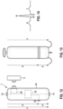
- Fig. 1 shows, in a schematic drawing, the human heart comprising the right atrium RA, the right ventricle RV, the left atrium LA and the left ventricle LV, the so-called sinoatrial node SAN being located in the wall of the right atrium RA, the sinoatrial node SAN being formed by a group of cells having the ability to spontaneously produce an electrical impulse that travels through the heart's electrical conduction system, thus causing the heart to contract in order to pump blood through the heart.
- the atrioventricular node AVN serves to coordinate electrical conduction in between the atria and the ventricles and is located at the lower back section of the intra-atrial septum near the opening of the coronary sinus.
- the HIS bundle H is extending, the HIS bundle H being comprised of heart muscle cells specialized for electrical conduction and forming part of the electrical conduction system for transmitting electrical impulses from the atrioventricular node AVN via the so-called right bundle branch RBB around the right ventricle RV and via the left bundle branch LBB around the left ventricle LV.
- HIS bundle pacing As electrical impulses from the atrioventricular node AVN are transmitted collectively via the HIS bundle H towards the right bundle branch RBB and the left bundle branch LBB for stimulating the right ventricle RV and the left ventricle LV, HIS bundle pacing has the potential to synchronously pace the right ventricle RV and the left ventricle LV, hence avoiding a lack of synchrony in between the left ventricle RV and the right ventricle RV as it may occur for example in a right ventricular pacing.
- a leadless pacemaker device 1 for implementation into the right atrium RA to provide for an HIS bundle pacing at the HIS bundle H, as schematically indicated in Fig. 1 .
- stimulation energy is injected into the right atrial wall at the HIS bundle H in order to provide for a pacing at the HIS bundle H.
- the leadless pacemaker is implanted in the high right ventricular septum in order to pace at or near the HIS from the ventricle (rather than from the atrium).
- This ventricular implant location may be better for patients with small atriums, and may have some implant stability advantages over atrial placement.
- a processor 15 and a communication interface 16 for communicating with an external device 3, such as a programmer wand, wherein in addition electrical and electronic components such as an energy storage in the shape of a battery are confined in the housing 10.
- the battery casing itself makes up part of the housing 10.
- the housing 10 provides for an encapsulation of components received therein, the housing 10 having the shape of, e.g., a cylindrical shaft having a length of for example a few centimeters.
- the leadless pacemaker device 1 comprises different electrodes 11, 12, 13 serving to emit pacing signals towards the HIS bundle H for providing HIS bundle pacing and to sense electrical signals indicative of cardiac activity, in particular indicative of atrial and ventricular contractions.
- a first electrode 11 herein is denoted as pacing electrode and is placed close to the HIS bundle H upon implanting the leadless pacemaker device 1.
- the first electrode 11 is placed at a tip of the housing 10 and is configured to engage with cardiac tissue in order to come to rest close to the HIS bundle H.
- a second electrode 12 serves as a counter electrode for the first electrode 11, a signal vector P arising between the first electrode 11 and the second electrode 12 providing for a pacing vector P for emitting pacing signals towards the HIS bundle H.
- the second electrode 12 serves as a sensing electrode for sensing signals, in particular relating to atrial and ventricular contractions.
- the second electrode 12 is placed at a distance from the first electrode 11 and for example has the shape of a ring.
- the second electrode 12 is for example placed at a distance of about 1 cm from the tip of the housing 10 at which the first electrode 11 is placed.
- the leadless pacemaker device 1 in the embodiment of Fig. 12 , in addition comprises a third electrode 13 placed at a far end of the housing 10, the third electrode 13 serving as a sensing electrode for sensing signals indicative of cardiac activity.
- a signal vector A arises between the third electrode 13 and the second electrode 12, the signal vector A picking up signals being indicative for example of atrial contractions.
- a signal vector F arises between the third electrode 13 and the first electrode 11, the signal vector F being indicative for example of ventricular contractions.
- the signal vector F also is denoted as farfield vector.
- the electrodes 11, 12, 13 are in operative connection with the processor 15, the processor 15 being configured to cause the first electrode 11 and the second electrode 12 to emit a pacing signal for stimulating the HIS bundle H for an HIS bundle pacing.
- the processor 15 furthermore is configured to process signals received via the electrodes 11, 12, 13 to provide for a sensing of cardiac activity, in particular atrial and ventricular contractions. By being able to record both atrial and ventricular activity, the leadless pacemaker device 1 can provide AV synchronous pacing.
- One challenge in implanting a leadless pacemaker device 1 at the HIS bundle H is to provide for a mapping in order to correctly place the leadless pacemaker device 1 with its pacing electrode 11 in close proximity to the HIS bundle H.
- the HIS bundle H shall be located by electrophysiological measurements in order to ensure that the leadless pacemaker device 1 is correctly placed at the HIS bundle H in order to provide for an effective HIS bundle pacing.
- the leadless pacemaker device 1 in a mapping mode is configured to sense a real-time electrogram in between the first electrode 11 and the second electrode 12 during placement of the leadless pacemaker device 1 in the human heart.
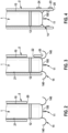
- the leadless pacemaker device 1 is received within a lumen of a catheter device 2 forming part of a delivery system, the leadless pacemaker device 1 being received at a distal end 20 of the catheter device 2 in order to deliver the leadless pacemaker device 1 into the human heart.
- the leadless pacemaker device 1 in one embodiment is partially deployed from the distal end 20 of the catheter device 2, as illustrated in Fig. 2 , such that the first electrode 11 and the second electrode 12 are exposed for sensing electrical cardiac signals in order to record a real-time electrogram.
- a recorded electrogram can be transferred to an external device 3 such as a programmer wand, such that the electrogram may be monitored and assessed in order to determine whether the HIS bundle H has been reached.
- the first electrode 11 is placed on a pin at a tip 100 of the housing 10 of the leadless pacemaker device 1.
- the first electrode 11 is inserted into cardiac tissue, in particular the right atrial wall (or in one embodiment, the high RV septum), such that via the first electrode 11 during actual pacing operation stimulation after implant energy may be transmitted towards the HIS bundle H for HIS bundle pacing.
- cardiac tissue in particular the right atrial wall (or in one embodiment, the high RV septum)
- the leadless pacemaker device 1 during placement sees, in terms of electrical coupling to the HIS bundle H, what the device 1 will see after implant during actual pacing operation. If during placement a HIS bundle capture is picked up via the first electrode 11 and the second electrode 12, it is ensured that also during actual pacing operation after implant stimulation energy can effectively be injected into the HIS bundle H.
- the communication interface 16 herein may be configured to provide for a communication by inductive coupling, by MICS, by a BLE, by acoustic communication, or by E-field communication. Signals indicative of a recorded real-time electrogram hence are transmitted using telemetry from the leadless pacemaker device 1 towards an external device 3 outside of the human body in the mapping mode.
- the catheter device 2 comprises a window 22 in the region at which the second electrode 12 is placed when the leadless pacemaker device 1 is received within the catheter device 2 for placement in the human heart.
- the leadless pacemaker device 1 can remain seated in the catheter device 2, hence potentially easing the placement of the leadless pacemaker device 1 in the right atrium RA as the leadless pacemaker device 1 does not stick out from the catheter device 2 during placement.
- the second electrode 12 is exposed in order to sense signals, wherein in addition the electrode 11 at the tip 100 of the housing 10 of the leadless pacemaker device 1 is exposed at the distal end 20 of the catheter device 2 such that a sensing vector can be picked up in between the electrodes 11, 12 for mapping.
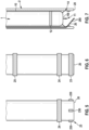
- mapping electrodes 23, 24 are arranged on the catheter device 2, a first mapping electrode 23 for example being placed immediately at the distal end 20 of the catheter device 2, and a second mapping electrode 24 being placed at a distance from the distal end 20 and hence from the first mapping electrode 23.
- the shape, size and distance of the electrodes 23, 24 herein, preferably, resembles the shape, size and distance of the electrodes 11, 12 of the leadless pacemaker device 1, such that an electrogram picked up via the mapping electrodes 23, 24 during placement resembles what the electrodes 11, 12 of the leadless pace maker device 1 will see during actual pacing operation after implant.
- first mapping electrode elements 230 may be circumferentially spaced with respect to each other at the distal end 20 of the catheter device 2, for example by an angle of 90° between neighboring electrode elements 230.
- the second mapping electrode 24 may for example have the shape of a ring circumferentially extending about the catheter device 2, wherein it is also conceivable that multiple second electrode elements making up the electrode 24 are present.
- Fig. 6 it also is conceivable to provide multiple electrodes 23, 24, 25 on the catheter device 2, the electrodes 23, 24, 25 being axially spaced apart and for example being shaped as rings extending about the catheter device 2.
- the electrodes 23, 24, 25 By means of such ring electrodes 23, 24, 25 nearfield and farfield vectors may be picked up, hence allowing to detect both a nearfield response and a farfield response.
- one or multiple of the electrodes 23, 24, 25 of the catheter device 2 are also used as flouro markers for additional visibility during implant.
- a mapping wire 26 is received in a side lumen of the catheter device 2 separate from the main lumen.
- the mapping wire 26 is angled towards the center of the catheter device 2 at the distal end 20, the mapping wire 26 carrying mapping electrodes 260 at its angled end, the electrodes 260 allowing to sense a mapping signal during implant of the leadless pacemaker device 1.
- a regular mapping catheter received in the main lumen is used for mapping when implanting the leadless pacemaker device 1.
- the leadless pacemaker device 1 in one embodiment, is to be placed in the right atrium RA, as this schematically as illustrated in Fig. 1 .
- the leadless pacemaker device 1 is to be fixed to the atrial wall, hence requiring a fixation device providing for a reliable and permanent fixture of the leadless pacemaker device 1 in the right atrium RA.
- a fixation device is to be designed such that a penetration of the atrial wall and a damage of the nerve structure near the HIS bundle H is prevented.
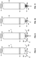
- a fixation device 14 at the tip 100 of the housing 10 of the leadless pacemaker device 1 comprises a multiplicity of curved fixation elements 140 being formed by wires in the shape of nitinol tines, the fixation elements 140 having for example a radius of curvature smaller than 1.5 mm in order to ensure that the fixation elements 140 do not penetrate deeply into the cardiac wall.
- the first electrode 11 is placed on a pin 110, the pin 110 engaging the atrial wall at the HIS bundle H during implant such that the electrode 11 comes to rest in close proximity to the HIS bundle H.
- the pin 110 has a pointed shape and has a length of for example in between 1 mm and 3 mm, for example approximately 2 mm.
- the second electrode 12 in the embodiment of Fig. 8 , has a ring shape and circumferentially extends about the housing 10 of the leadless pacemaker device 1, the housing 10 having a generally cylindrical shape.
- a third electrode 13 is placed at a far end 101 of the housing 10 opposite the first electrode 11.
- multiple (here: three) first electrodes 11 are placed on multiple pins 110 at the tip 100 of the housing 10 of the leadless pacemaker device 1.
- the pins 110 engage with cardiac tissue, the processor device 15 for example being configured to select one or a group of the first electrodes 11.
- an electrode of the first electrodes 11 may be chosen which is arranged closest to the HIS bundle H and hence has the strongest electrical coupling with the HIS bundle H. Because multiple first electrodes 11 are available for selection, a potential need for repositioning the leadless pacemaker device 1 during implant at least can be reduced.
- the fixation device 14 comprises a screw anchor 141, the screw anchor 141 serving to screw into cardiac tissue in order to fix the leadless pacemaker device 1 within the right atrium RA.
- the first electrode 11 herein is placed at a tip of the screw anchor 141, such that by engagement of the screw anchor 141 in cardiac tissue the electrode 11 comes to rest in close proximity to the HIS bundle H.
- the screw anchor 141 may for example have a diameter equal to or smaller than 2 mm in order to minimize the risk for damaging the nerve structure near the HIS bundle H during implant.
- the screw anchor 141 may comprise multiple arms to form a double or triple helix, each arm for example carrying a first electrode 11 such that - similar to the embodiment of Fig. 9 - the processor 15 may be configured to select one or a group of the electrodes 11 for operation in order to select such electrode 11 which is closest and best coupled to the HIS bundle H.
- a single screw anchor 141 contains multiple electrodes along its length, each individually selectable by the processor 15.
- the pin 110 respectively the screw anchor 141 may comprise an electrically insulating coating, such that only the electrode 11 is electrically exposed. This may help to reduce the risk of accidental atrial capture.
- the processor 15 may switch between a sensing mode and a stimulation mode in order to sense signals indicative of cardiac activity and to generate pacing signals for stimulating the HIS bundle H in an alternating fashion.
- Atrial contractions may be sensed for example by a signal vector A in between the second electrode 12 and the third electrode 13 as illustrated in Fig. 12 and 13 .
- a pacing signal is emitted by means of a pacing vector P in between the first electrode 11 and the second electrode 12 in order to inject stimulation energy at the HIS bundle H, the pacing signal being injected with adequate timing after the atrial capture in order to provide for atrial to ventricular (A to V) synchrony.
- the processor 15 may switch back into a sensing mode in order to sense an evoked response by picking up ventricular contractions via the farfield vector F in between the first electrode 11 and the third electrode 13.
- An atrial sensing algorithm may for example be similar to an atrial DX algorithm.
- For sensing ventricular signals an increased amplification may be required as for the leadless pacemaker 1 ventricular contractions occur in the farfield and hence require a stronger amplification.
- an automated capture algorithm may be used.
- the QRS waveform in the ECG as illustrated in Fig. 14 may be examined, a short QRS waveform indicating a capture of the HIS conduction pathway without recruitment of surrounding cardiac tissue.
- An automated capture algorithm herein may include a periodic search, for example once per hour, by increasing and decreasing the pacing threshold and by monitoring a QRS response.
- the processor 15 may then for example be configured to choose the pacing amplitude having the smallest QRS width, wherein for the further pacing operation the pacing amplitude determined in this way may be used.
- FIG. 15 An embodiment of an atrial sensing algorithm is illustrated in the table of Fig. 15 .
- the processor 15 may be configured to attempt to synchronize with atrial activity that is present but not detected.
- the timing of the pacing may be adapted. For example, if a previous intrinsic distance between ventricular signals (V-V) has been X milliseconds, the next pacing signal should be injected earlier than the intrinsic V-V of the previous cycle by some value, for example by 10% or 10 ms (third row in the table of Fig. 15 ). This causes a shortening of the A/V.
- the processor 15 should be configured to periodically check the intrinsic V-V by allowing intrinsic conduction, for example once in a minute or once every 5 minutes.
- FIG. 16 an embodiment of a ventricular sensing algorithm to capture an evoked response is illustrated.
- the leadless pacemaker device 1 Since the leadless pacemaker device 1 is placed in the right atrium RA, it can sense the atrial signal with its atrial dipole in between the second electrode 12 and the third electrode 13. If the device should detect that the patient is in a state of atrial fibrillation (AF), the processor is configured to drive the ventricle by pacing the AF rate as set by the clinician. Driving the ventricle during the state of AF is desirable because it will continue to provide LV-RV synchrony, which may not be present in intrinsic beats.
- AF atrial fibrillation
Abstract
Description
- The instant invention generally relates to a leadless cardiac pacemaker device.
- In recent years, leadless pacemakers have received increasing attention. Leadless pacemakers, in contrast to pacemakers implanted subcutaneously using leads extending transvenously into the heart, avoid leads in that the pacemaker device itself is implanted into the heart, the pacemaker having the shape of a capsule for implantation into cardiac tissue, in particular the right ventricular wall of the right ventricle. Such leadless pacemakers exhibit the inherent advantage of not using leads, which can reduce risks for the patient involved with leads transvenously accessing the heart, such as the risk of pneumothorax, lead dislodgement, lead endocarditis, cardiac perforation, venous thrombosis and the like.
- Leadless pacemakers are currently designed for implantation in the right ventricle and during implant are placed in or on the right ventricular wall. As such leadless pacemakers primarily cause a pacing of the right ventricle, drawbacks coming with existing leadless pacemakers may include a reduction in the right ventricular filling volume, a lack of the so-called A to V synchrony (relating to the proper sequence of atrial and ventricular contractions), a potentially excessive right ventricular pacing (which cannot be minimized due to the placement of the leadless pacemaker in the right ventricle), and a lack of left ventricular (LV) to right ventricular (RV) synchrony.
- Approaches exist to provide for a so-called HIS bundle pacing in order to synchronously pace both the right ventricle and the left ventricle by injecting a stimulus via the HIS bundle. Current pacemaker devices for HIS bundle pacing, as known for example from
US 8,565,880 andUS 8,078,287 , however use leads extending from the pacemaker device transvenously into the heart to excess the HIS bundle. -
US 8,078,287 herein describes a mapping technique for placing a lead in the right ventricle by monitoring cardiac signals to obtain electrograms including so-called A, V, and H waves, A waves corresponding to the right atrial depolarization sensed by a mapping electrode, V waves corresponding to the right ventricular depolarization sensed by a mapping electrode, and H waves corresponding to events indicative of A/V conduction of electrical impulses as recorded by a mapping electrode. - There is a desire to provide a pacemaker device which may exhibit the advantages of a leadless pacemaker, while avoiding drawbacks such as a lack of A to V synchrony and left ventricular (LV) to right ventricular (RV) synchrony as inherent with right ventricular pacing.
- Such desires are addressed by a leadless cardiac pacemaker device according to present claim 1. Further embodiments are subject matter of the dependent claims.
- In one aspect, the pacemaker device comprises a housing having a tip; a first electrode arranged on the housing in the vicinity of the tip, the first electrode being configured to engage with intra-cardiac tissue; a second electrode arranged on the housing at a distance from the tip of the housing; a third electrode arranged on the housing, wherein the housing comprises a far end opposite the tip, the third electrode being arranged in the vicinity of the far end; and a processor enclosed in the housing and operatively connected to the first electrode and the second electrode, wherein the processor is configured to process a reception signal received by at least one of the first electrode and the second electrode and to generate a pacing signal to be admitted using at least one of the first electrode and the second electrode, and wherein the processor is configured to process, as a reception signal, at least one of a second signal vector sensed between the first electrode and the third electrode and a third signal vector sensed between the second electrode and the third electrode.
- Hence a leadless cardiac pacemaker device is proposed that is in particular configured to provide HIS bundle pacing. By providing a pacing at the HIS bundle, drawbacks associated with current leadless pacemakers can be avoided, for example allowing to avoid a reduction in the right ventricular filling volume, to improve the atrial to ventricular (A/V) synchrony, to avoid a predominant right ventricular pacing, and to improve the left ventricular (LV) to right ventricular (RV) synchrony. In particular, by pacing at the HIS bundle, the intrinsic conductive system of the heart is used, providing for a synchronous stimulation of the right ventricle and the left ventricle via the intrinsic right bundle branch and left bundle branch extending from the HIS bundle to extend about the right ventricle respectively the left ventricle. Hence, a synchronous pacing for both the right ventricle and the left ventricle is provided, avoiding an asynchronous and asymmetric pacing of the ventricles.
- The housing provides for an encapsulation of the leadless pacemaker device, the leadless pacemaker device including all required components for autarkic operation, such as a processor, an energy storage such as a battery, electric and electronic circuitry and the like, within the housing. The processor may be any kind of control logic such as a microprocessor, a microcontroller, or one or more finite state machine(s). A finite state machine uses less power than a microprocessor but has less flexibility and less programmability. The housing is fluid-tight such that the leadless pacemaker device may be implanted into the heart and may be kept close to cardiac tissue over an extended period of time to provide for a long-time, continuous cardiac pacing operation.
- The leadless pacemaker device, in one aspect, is to be placed in the right atrium. The pacemaker device hence is not placed in the right ventricle, but on an atrial wall, which makes it necessary to provide an adapted fixation for the pacemaker device by fixing it to the atrial wall.
- In one aspect, the leadless pacemaker device comprises a fixation device having at least one fixation element arranged at the tip of the housing for fixing the pacemaker device to intra-cardiac tissue, in particular the atrial wall. In one embodiment, one or multiple fixation elements in the shape of thin wires, for example nitinol tines exhibiting a shape memory effect, may be provided, such wires for example having a curvature comprising a small radius, for example smaller than 1.5 mm and hence exhibiting a rather tight curvature in order to minimize the chance that such fixation elements penetrate the atrial wall. In another embodiment, a fixation element in the shape of a screw anchor may be provided, such screw anchor allowing to screw the leadless pacemaker device into the atrial wall and having a rather small diameter, for example smaller than 2 mm.
- The fixation device at the tip of the housing of the leadless pacemaker device allows to place the leadless pacemaker device on the atrial wall and to fix the leadless pacemaker device via the fixation device to the atrial wall, such that the leadless pacemaker device upon implantation is fixedly held and permanently placed within cardiac tissue.
- In one aspect, the first electrode arranged in the vicinity of the tip of the housing is located on a pin fixed to the housing, the pin serving to engage with cardiac tissue when implanting the leadless pacemaker device. The pin has a pointed shape and is inserted into cardiac tissue, in particular the atrial wall in the vicinity of the HIS bundle, such that the first electrode placed on the tip comes to rest at a location close to the HIS bundle for injecting a stimulating signal towards the HIS bundle for HIS bundle pacing.
- The pin may for example have a length between 1 mm and 2 mm, for example approximately 1.5 mm.
- In another embodiment, the first electrode may be placed on a screw anchor serving as a fixation element for the fixation device. Such screw anchor is inserted into cardiac tissue, in particular the atrial wall, when placing the leadless pacemaker device in the heart. The first electrode arranged on the screw anchor in this way comes to rest at a location close to the HIS bundle for providing for an effective HIS bundle pacing.
- The pin or the screw anchor may carry a coating for (partial) insulation such that only the first electrode placed on the pin respectively the screw anchor is exposed. This may allow minimizing a risk of accidental atrial capture. The insulating coating can be paralyne, PTFE (PTFE - Polytetrafluoroethylene), silicone, a silicone polymer, polyurethane, polyimide, or some other biocompatible coating.
- In one aspect, the leadless pacemaker device comprises a multiplicity of first electrodes arranged on the housing in the vicinity of the tip. For example, multiple pins may be provided at the tip of the housing (e.g. two or three pins), each pin carrying a first electrode. Alternatively, a screw anchor device having multiple arms to form a double or triple helix or the like may be provided, each arm carrying a first electrode.
- The processor herein, in one embodiment, may be configured to select at least one of the multiplicity of the first electrodes for operation, for example for receiving a reception signal and/or for emitting a pacing signal. By selecting a proper first electrode located particularly close to the HIS bundle, an effective HIS bundle pacing may be achieved. Because multiple first electrodes are present, the selection of a suitable first electrode allows to easily and effectively stimulate the HIS bundle without having to reposition the leadless pacemaker.
- In one aspect, the second electrode is formed by an electrode ring circumferentially extending about the housing. Alternatively, the second electrode may for example be formed by a patch or another electrically conductive area formed on the housing. The second electrode is placed at a distance from the tip of the housing and hence at a distance from the first electrode arranged in the vicinity of the tip.
- In one embodiment with a multiplicity of first electrodes, two or more of the multiplicity of the first electrodes can be selected to pace differentially between. This allows for an even larger number of pacing vectors than always using the second electrode as the pacing return. This helps to maximize the chance that the device can be programed to stimulate the HIS bundle without repositioning. The cost of this approach may be longevity, since higher pacing voltages will likely be needed since the first electrodes may have higher impedance than the (large) second electrode.
- One challenge in the context of implanting a leadless pacemaker for HIS bundle pacing is detecting the HIS bundle in order to place the leadless pacemaker in close proximity to the HIS bundle for effective pacing. In one embodiment, the processor of the leadless pacemaker device is configured to process, as a reception signal in a mapping mode during placement of the pacemaker device in a human heart, a first signal vector sensed between the first electrode and the second electrode. The leadless pacemaker device, by means of the first signal vector, hence may take up an electrogram in real-time, the electrogram being indicative of electrical activity at or close to the HIS bundle. Because the first electrode and the second electrode may also be used for the pacing to emit a pacing signal towards the HIS bundle for stimulation, the signal vector picked up by means of the first electrode and the second electrode during placement resembles what the leadless pacemaker device will see during actual operation after implant, because the same electrodes are used for mapping and for pacing after implant. A strong signal reception during placement hence is indicative of an effective energy injection for pacing after implant.
- In one embodiment, the leadless pacemaker device comprises a communication interface for transmitting, in the mapping mode, a communication signal comprising information relating to said first signal vector from the pacemaker device to an external device outside of the human body, for example in the shape of a programmer wand. The communication interface serves to contactlessly (wirelessly) transmit communication signals from the leadless pacemaker device towards the external device, information hence being transmitted from the leadless pacemaker device to the external device using telemetry. In this way, a real-time electrogram picked up by means of the first electrode and the second electrode may be transmitted to the external device, such that the electrogram may be monitored for achieving a mapping in order to access the HIS bundle by the leadless pacemaker device. In one embodiment the real-time electrogram can also be programmed to be between any two first electrodes, or between multiple first electrodes electrically tied together and the second electrode. The different allowed sensing vectors allow the implanter to search a bit electronically for a HIS signal without necessarily having to physically reposition the electrodes.
- The communication interface may for example be configured to transmit communication signals using an inductive coupling, MICS (medical implant communication service), BLE (Bluetooth low energy), acoustic communication, or E-field communication.
- The third electrode is operatively connected to the processor, such that the processor is enabled to receive and process signals received via the third electrode.
- The second signal vector arising between the first electrode and the third electrode herein may also be referred to as farfield vector, the first electrode and the third electrode exhibiting a distance with respect to each other larger than the second electrode and the third electrode. The second signal vector may in particular be indicative of ventricular contractions, such that by means of the second signal vector an evoked response after injecting a pacing stimulus may be captured.
- The third signal vector sensed between the second electrode and the third electrode may be used to sense atrial contractions in order to provide for an atrial to ventricular synchronization by timely injecting a stimulus at the HIS bundle following atrial contractions. The third signal vector may alternatively or in addition also be used to sense ventricular contractions, in response to an HIS bundle pacing stimulus, wherein in this case atrial contractions need to be filtered out of the third signal vector.
- In one aspect, the same set (or sub-set) of electrodes of the leadless pacemaker device is used both for sensing contraction signals as well as for emitting pacing stimulation signals. For this, in one embodiment, the processor of the leadless pacemaker device is configured to switch between a sensing mode and a stimulus mode by alternating between the processing of received signals and the generation of pacing signals. In particular, the processor may be configured to, in a first phase of the cardiac cycle, sense for atrial contractions. If atrial contractions are captured, the processor may switch to a stimulus mode in which a pacing signal is generated and emitted using at least one of the first electrode and the second electrode in a second phase of the cardiac cycle. After the pacing signal has been emitted, the processor switches back to a sensing mode to now sense ventricular contractions which are evoked as a response to the pacing stimulus, the ventricular contractions for example being picked up by the second signal vector sensed between the first electrode and the third electrode in a third phase of the cardiac cycle. Following the sensing of ventricular contractions, atrial contractions may be sensed anew to continue pacing operation.
- In another aspect, a delivery system for placement of a leadless pacemaker device in a human heart is provided, the delivery system comprising: a catheter device for insertion into the human body, the catheter device comprising a lumen and a distal end to be inserted into the human body; and a leadless pacemaker device configured to provide HIS bundle pacing, the pacemaker device being received within the lumen in the vicinity of the distal end of the catheter device; and a first mapping electrode and a second mapping electrode arranged in the vicinity of the distal end of the catheter device for sensing, in a mapping mode, a mapping signal vector in between the first mapping electrode and the second mapping electrode, the mapping signal vector representing an electrogram of cardiac activity.
- The delivery system serves to place the leadless pacemaker device in the human heart such that the leadless pacemaker device comes to rest for example in the right atrium in close proximity to the HIS bundle. The delivery system herein provides for a mapping such that during placement of the leadless pacemaker device it may be observed whether the leadless pacemaker device has reached the HIS bundle and hence has obtained its correct position within e.g. the atrium.
- To provide for a mapping, the delivery system comprises a first mapping electrode and a second mapping electrode. The first mapping electrode and the second mapping electrode serve to pick up a mapping signal vector, the mapping signal vector representing an electrogram of cardiac activity, for example an HIS bundle electrogram picked up at the HIS bundle and suitable to assess whether the HIS bundle has suitably been approached.
- Different arrangements of the first mapping electrode and the second mapping electrode are conceivable.
- In one embodiment, the pacemaker device comprises a housing having a tip, the first mapping electrode being arranged on the housing in the vicinity of the tip, the second mapping electrode being arranged on the housing at a distance from the tip, wherein the pacemaker device comprises a communication interface for transmitting a communication signal comprising information relating to said mapping signal vector from the pacemaker device to an external device outside of the human body. In this embodiment, the first mapping electrode and the second mapping electrode are part of the leadless pacemaker device. The first mapping electrode and the second mapping electrode may, during actual operation once implanted, also be used for emitting a pacing signal for stimulating the HIS bundle, such that in a mapping mode by means of the first mapping electrode and the second mapping electrode an electrogram is picked up which resembles what the leadless pacemaker electrically sees during actual operation.
- If the first mapping electrode and the second mapping electrode are arranged on the leadless pacemaker, care must be taken that signals can be picked up by the first mapping electrode and the second mapping electrode during placement of the leadless pacemaker device by means of the catheter device. For this, the leadless pacemaker device, for mapping, may partially be deployed from the catheter device by pulling back the catheter device to expose the first mapping electrode and the second mapping electrode of the pacemaker device.
- In another example, the catheter device may comprise at least one window exposing for example the second mapping electrode, in which case the leadless pacemaker device does not necessarily need to be partially deployed for mapping. This may ease the placement of the pacemaker device, as during placement the pacemaker device is not sticking out substantially from the catheter device, but can be received within the catheter device.
- In another example, the first mapping electrode and the second mapping electrode are arranged on the catheter device. The first mapping electrode herein may be placed immediately at the distal end of the catheter device, wherein the second mapping electrode may be placed at a distance from the distal end. In one embodiment, the distance between the first mapping electrode and the second mapping electrode herein matches the distance between a first electrode and a second electrode arranged on the leadless pacemaker device for generating and emitting a pacing signal for stimulating the HIS bundle. In this way it can be achieved that during placement an electrogram from the catheter device is sensed which matches what the leadless pacemaker device sees during actual operation in an implanted state.
- In one example, multiple first mapping electrodes and/or second mapping electrodes are placed on the catheter device, for example spaced with respect to each other along a circumferential direction about the catheter device, for example such that neighboring mapping electrodes are spaced apart by an angle of 90°. In this way multiple mapping vectors can be sensed, allowing to derive information with respect to the direction of signal reception during mapping.
- In addition or alternatively, multiple ring mapping electrodes can be used to sense a nearfield response and a farfield response, allowing to obtain further information from other regions of the heart to derive mapping information.
- The mapping electrodes placed on the catheter device may, by suitable electrical circuit conductors running along the catheter device, be connected with an external monitoring circuitry.
- In one example, one of the mapping electrodes of the catheter device may also be used as a flouro marker to provide additional visibility during implant.
- In another example, the first mapping electrode and the second mapping electrode may be placed on a mapping wire received within the catheter device, for example in the lumen or in a side lumen separate from the main lumen. Because the catheter device does not need to comprise additional mapping electrodes in this case, the construction of the catheter device is less complex. The mapping wire may be angled to traverse towards the center of the delivery catheter at the distal end of the catheter device, allowing to sense a mapping signal close to the location at which a pacing electrode of the leadless pacemaker device will be placed after implant.
- The mapping electrodes placed on the mapping wire may be connected, by means of suitable electric circuit conductors running along the mapping wire, with an external monitoring circuitry.
- In another example, a conventional mapping catheter passing through a main lumen of the catheter device may be used.
- In another aspect, a method for placing a leadless pacemaker device using a delivery system as described above is provided, the method comprising: in a mapping mode, sensing, using the first mapping electrode and the second mapping electrode arranged in the vicinity of the distal end of the catheter device, a first mapping signal vector in between the first mapping electrode and the second mapping electrode, the mapping signal vector representing an electrogram of cardiac activity.
- The various features and advantages of the present invention may be more readily understood with reference to the following detailed description and the embodiments shown in the drawings. Herein,
- Fig. 1
- shows a schematic view of the human heart, including the Sinotrial node, the Atrioventricular node, the HIS bundle and the left bundle branch and right bundle branch extending from the HIS bundle;
- Fig. 2
- shows a view of an embodiment of a leadless pacemaker device received within a catheter device, partially deployed for mapping during placement;
- Fig. 3
- shows a view of another embodiment of a leadless pacemaker device received within the catheter device;
- Fig. 4
- shows a view of yet another embodiment of a leadless pacemaker device received within a catheter device during placement;
- Fig. 5
- shows a schematic view of a catheter device having electrodes at a tip;
- Fig. 6
- shows a schematic view of another example of a catheter device;
- Fig. 7
- shows a view of an embodiment of a leadless pacemaker device received in a catheter device, a mapping wire being received within the catheter device for mapping;
- Fig. 8
- shows an embodiment of a leadless pacemaker device;
- Fig. 9
- shows another embodiment of a leadless pacemaker device;
- Fig. 10
- shows yet another embodiment of a leadless pacemaker device;
- Fig. 11
- shows yet another embodiment of a leadless pacemaker device;
- Fig. 12
- shows a schematic view of a leadless pacemaker device;
- Fig. 13
- shows a schematic view of a leadless pacemaker device, indicating signal vectors sensed between different electrodes of the leadless pacemaker device;
- Fig. 14
- shows an electrocardiogram signal;
- Fig. 15
- shows a table illustrating an atrial detection algorithm; and
- Fig. 16
- shows a table illustrating a ventricular detection algorithm.
- Subsequently, embodiments of the invention shall be described in detail with reference to the drawings. In the drawings, like reference numerals designate like structural elements.
- It is to be noted that the embodiments are not limiting for the invention, but merely represent illustrative examples.
- In the instant invention it is proposed to provide a leadless pacemaker device providing for HIS bundle pacing.
-
Fig. 1 shows, in a schematic drawing, the human heart comprising the right atrium RA, the right ventricle RV, the left atrium LA and the left ventricle LV, the so-called sinoatrial node SAN being located in the wall of the right atrium RA, the sinoatrial node SAN being formed by a group of cells having the ability to spontaneously produce an electrical impulse that travels through the heart's electrical conduction system, thus causing the heart to contract in order to pump blood through the heart. The atrioventricular node AVN serves to coordinate electrical conduction in between the atria and the ventricles and is located at the lower back section of the intra-atrial septum near the opening of the coronary sinus. From the atrioventricular node AVN the so-called HIS bundle H is extending, the HIS bundle H being comprised of heart muscle cells specialized for electrical conduction and forming part of the electrical conduction system for transmitting electrical impulses from the atrioventricular node AVN via the so-called right bundle branch RBB around the right ventricle RV and via the left bundle branch LBB around the left ventricle LV. - As electrical impulses from the atrioventricular node AVN are transmitted collectively via the HIS bundle H towards the right bundle branch RBB and the left bundle branch LBB for stimulating the right ventricle RV and the left ventricle LV, HIS bundle pacing has the potential to synchronously pace the right ventricle RV and the left ventricle LV, hence avoiding a lack of synchrony in between the left ventricle RV and the right ventricle RV as it may occur for example in a right ventricular pacing.
- Whereas common pacemaker devices providing for an HIS bundle pacing use leads extending from the (subcutaneously implanted) pacemaker device transvenously into the heart, it is proposed within the instant invention to use a leadless pacemaker device 1 for implementation into the right atrium RA to provide for an HIS bundle pacing at the HIS bundle H, as schematically indicated in
Fig. 1 . By means of such leadless pacemaker device 1, stimulation energy is injected into the right atrial wall at the HIS bundle H in order to provide for a pacing at the HIS bundle H. - In another embodiment, the leadless pacemaker is implanted in the high right ventricular septum in order to pace at or near the HIS from the ventricle (rather than from the atrium). This ventricular implant location may be better for patients with small atriums, and may have some implant stability advantages over atrial placement.
- Referring now to
Fig. 12 , in one embodiment a leadless pacemaker device 1 configured to provide for an HIS bundle pacing comprises ahousing 10 enclosing electrical and electronic components for operating the leadless pacemaker device 1. In particular, enclosed within thehousing 10 is aprocessor 15 and acommunication interface 16 for communicating with anexternal device 3, such as a programmer wand, wherein in addition electrical and electronic components such as an energy storage in the shape of a battery are confined in thehousing 10. In one embodiment the battery casing itself makes up part of thehousing 10. Thehousing 10 provides for an encapsulation of components received therein, thehousing 10 having the shape of, e.g., a cylindrical shaft having a length of for example a few centimeters. - In the embodiment of
Fig. 12 , the leadless pacemaker device 1 comprisesdifferent electrodes - A
first electrode 11 herein is denoted as pacing electrode and is placed close to the HIS bundle H upon implanting the leadless pacemaker device 1. Thefirst electrode 11 is placed at a tip of thehousing 10 and is configured to engage with cardiac tissue in order to come to rest close to the HIS bundle H. - A
second electrode 12 serves as a counter electrode for thefirst electrode 11, a signal vector P arising between thefirst electrode 11 and thesecond electrode 12 providing for a pacing vector P for emitting pacing signals towards the HIS bundle H. In addition, thesecond electrode 12 serves as a sensing electrode for sensing signals, in particular relating to atrial and ventricular contractions. Thesecond electrode 12 is placed at a distance from thefirst electrode 11 and for example has the shape of a ring. Thesecond electrode 12 is for example placed at a distance of about 1 cm from the tip of thehousing 10 at which thefirst electrode 11 is placed. - The leadless pacemaker device 1, in the embodiment of
Fig. 12 , in addition comprises athird electrode 13 placed at a far end of thehousing 10, thethird electrode 13 serving as a sensing electrode for sensing signals indicative of cardiac activity. In particular, a signal vector A arises between thethird electrode 13 and thesecond electrode 12, the signal vector A picking up signals being indicative for example of atrial contractions. In addition, a signal vector F arises between thethird electrode 13 and thefirst electrode 11, the signal vector F being indicative for example of ventricular contractions. The signal vector F also is denoted as farfield vector. - The
electrodes processor 15, theprocessor 15 being configured to cause thefirst electrode 11 and thesecond electrode 12 to emit a pacing signal for stimulating the HIS bundle H for an HIS bundle pacing. Theprocessor 15 furthermore is configured to process signals received via theelectrodes - One challenge in implanting a leadless pacemaker device 1 at the HIS bundle H is to provide for a mapping in order to correctly place the leadless pacemaker device 1 with its
pacing electrode 11 in close proximity to the HIS bundle H. Within a mapping technique, the HIS bundle H shall be located by electrophysiological measurements in order to ensure that the leadless pacemaker device 1 is correctly placed at the HIS bundle H in order to provide for an effective HIS bundle pacing. - Referring now to
Fig. 2 , in one embodiment the leadless pacemaker device 1 in a mapping mode is configured to sense a real-time electrogram in between thefirst electrode 11 and thesecond electrode 12 during placement of the leadless pacemaker device 1 in the human heart. For placement, the leadless pacemaker device 1 is received within a lumen of acatheter device 2 forming part of a delivery system, the leadless pacemaker device 1 being received at adistal end 20 of thecatheter device 2 in order to deliver the leadless pacemaker device 1 into the human heart. - For mapping, the leadless pacemaker device 1 in one embodiment is partially deployed from the
distal end 20 of thecatheter device 2, as illustrated inFig. 2 , such that thefirst electrode 11 and thesecond electrode 12 are exposed for sensing electrical cardiac signals in order to record a real-time electrogram. By means of thecommunication interface 16 as illustrated inFig. 12 a recorded electrogram can be transferred to anexternal device 3 such as a programmer wand, such that the electrogram may be monitored and assessed in order to determine whether the HIS bundle H has been reached. - In the embodiment of
Fig. 2 , thefirst electrode 11 is placed on a pin at atip 100 of thehousing 10 of the leadless pacemaker device 1. Upon implant, thefirst electrode 11 is inserted into cardiac tissue, in particular the right atrial wall (or in one embodiment, the high RV septum), such that via thefirst electrode 11 during actual pacing operation stimulation after implant energy may be transmitted towards the HIS bundle H for HIS bundle pacing. Because, in the mapping mode, sensing signals are received via thefirst electrode 11 and thesecond electrode 12, the leadless pacemaker device 1 during placement sees, in terms of electrical coupling to the HIS bundle H, what the device 1 will see after implant during actual pacing operation. If during placement a HIS bundle capture is picked up via thefirst electrode 11 and thesecond electrode 12, it is ensured that also during actual pacing operation after implant stimulation energy can effectively be injected into the HIS bundle H. - As the electrogram recorded via the
first electrode 11 and thesecond electrode 12 during placement is communicated towards the outside via thecommunication interface 16, the electrogram may be monitored and may be assessed in order to evaluate whether correct placement has been achieved. Thecommunication interface 16 herein may be configured to provide for a communication by inductive coupling, by MICS, by a BLE, by acoustic communication, or by E-field communication. Signals indicative of a recorded real-time electrogram hence are transmitted using telemetry from the leadless pacemaker device 1 towards anexternal device 3 outside of the human body in the mapping mode. - Referring now to
Fig. 3 , in another embodiment thecatheter device 2 comprises awindow 22 in the region at which thesecond electrode 12 is placed when the leadless pacemaker device 1 is received within thecatheter device 2 for placement in the human heart. In this embodiment, no partial deployment of the leadless pacemaker device 1 for placement is necessary, but the leadless pacemaker device 1 can remain seated in thecatheter device 2, hence potentially easing the placement of the leadless pacemaker device 1 in the right atrium RA as the leadless pacemaker device 1 does not stick out from thecatheter device 2 during placement. By means of thewindow 22 thesecond electrode 12 is exposed in order to sense signals, wherein in addition theelectrode 11 at thetip 100 of thehousing 10 of the leadless pacemaker device 1 is exposed at thedistal end 20 of thecatheter device 2 such that a sensing vector can be picked up in between theelectrodes - Referring now to
Fig. 4 , in anotherembodiment mapping electrodes catheter device 2, afirst mapping electrode 23 for example being placed immediately at thedistal end 20 of thecatheter device 2, and asecond mapping electrode 24 being placed at a distance from thedistal end 20 and hence from thefirst mapping electrode 23. The shape, size and distance of theelectrodes electrodes mapping electrodes electrodes - Referring now to
Fig. 5 , different shapes and arrangements of theelectrodes catheter device 2 are conceivable. For example, multiple firstmapping electrode elements 230 may be circumferentially spaced with respect to each other at thedistal end 20 of thecatheter device 2, for example by an angle of 90° between neighboringelectrode elements 230. Thesecond mapping electrode 24 may for example have the shape of a ring circumferentially extending about thecatheter device 2, wherein it is also conceivable that multiple second electrode elements making up theelectrode 24 are present. By using multiple electrode elements it may be possible to pick up different mapping signal vectors, allowing for example to derive information indicative of a direction of signal reception, hence further facilitating the placement and mapping for arranging the leadless pacemaker device 1 at the HIS bundle H. - Referring now to
Fig. 6 , it also is conceivable to providemultiple electrodes catheter device 2, theelectrodes catheter device 2. By means ofsuch ring electrodes - In one embodiment, one or multiple of the
electrodes catheter device 2 are also used as flouro markers for additional visibility during implant. - Referring now to
Fig. 7 , in another embodiment amapping wire 26 is received in a side lumen of thecatheter device 2 separate from the main lumen. Themapping wire 26 is angled towards the center of thecatheter device 2 at thedistal end 20, themapping wire 26 carryingmapping electrodes 260 at its angled end, theelectrodes 260 allowing to sense a mapping signal during implant of the leadless pacemaker device 1. - In another embodiment, a regular mapping catheter received in the main lumen is used for mapping when implanting the leadless pacemaker device 1.
- The leadless pacemaker device 1, in one embodiment, is to be placed in the right atrium RA, as this schematically as illustrated in
Fig. 1 . For the implant, the leadless pacemaker device 1 is to be fixed to the atrial wall, hence requiring a fixation device providing for a reliable and permanent fixture of the leadless pacemaker device 1 in the right atrium RA. - As the atrial wall of the right atrium RA typically is comparatively thin and more delicate than for example the ventricular wall, a fixation device is to be designed such that a penetration of the atrial wall and a damage of the nerve structure near the HIS bundle H is prevented.
- Referring now to
Fig. 8 , in one embodiment, afixation device 14 at thetip 100 of thehousing 10 of the leadless pacemaker device 1 comprises a multiplicity ofcurved fixation elements 140 being formed by wires in the shape of nitinol tines, thefixation elements 140 having for example a radius of curvature smaller than 1.5 mm in order to ensure that thefixation elements 140 do not penetrate deeply into the cardiac wall. - In the embodiment of
Fig. 8 , thefirst electrode 11 is placed on apin 110, thepin 110 engaging the atrial wall at the HIS bundle H during implant such that theelectrode 11 comes to rest in close proximity to the HIS bundle H. Thepin 110 has a pointed shape and has a length of for example in between 1 mm and 3 mm, for example approximately 2 mm. - The
second electrode 12, in the embodiment ofFig. 8 , has a ring shape and circumferentially extends about thehousing 10 of the leadless pacemaker device 1, thehousing 10 having a generally cylindrical shape. Athird electrode 13 is placed at afar end 101 of thehousing 10 opposite thefirst electrode 11. - Referring now to
Fig. 9 , in one embodiment multiple (here: three)first electrodes 11 are placed onmultiple pins 110 at thetip 100 of thehousing 10 of the leadless pacemaker device 1. During implant thepins 110 engage with cardiac tissue, theprocessor device 15 for example being configured to select one or a group of thefirst electrodes 11. In this way an electrode of thefirst electrodes 11 may be chosen which is arranged closest to the HIS bundle H and hence has the strongest electrical coupling with the HIS bundle H. Because multiplefirst electrodes 11 are available for selection, a potential need for repositioning the leadless pacemaker device 1 during implant at least can be reduced. - Referring now to
Fig. 10 , in one embodiment thefixation device 14 comprises ascrew anchor 141, thescrew anchor 141 serving to screw into cardiac tissue in order to fix the leadless pacemaker device 1 within the right atrium RA. Thefirst electrode 11 herein is placed at a tip of thescrew anchor 141, such that by engagement of thescrew anchor 141 in cardiac tissue theelectrode 11 comes to rest in close proximity to the HIS bundle H. Thescrew anchor 141 may for example have a diameter equal to or smaller than 2 mm in order to minimize the risk for damaging the nerve structure near the HIS bundle H during implant. - In one embodiment, the
screw anchor 141 may comprise multiple arms to form a double or triple helix, each arm for example carrying afirst electrode 11 such that - similar to the embodiment ofFig. 9 - theprocessor 15 may be configured to select one or a group of theelectrodes 11 for operation in order to selectsuch electrode 11 which is closest and best coupled to the HIS bundle H. In another embodiment asingle screw anchor 141 contains multiple electrodes along its length, each individually selectable by theprocessor 15. - In the embodiments of
Fig. 8 to 11 , thepin 110 respectively thescrew anchor 141 may comprise an electrically insulating coating, such that only theelectrode 11 is electrically exposed. This may help to reduce the risk of accidental atrial capture. - During an actual pacing operation, the
processor 15 may switch between a sensing mode and a stimulation mode in order to sense signals indicative of cardiac activity and to generate pacing signals for stimulating the HIS bundle H in an alternating fashion. - In particular, in a first phase of the cardiac cycle, atrial contractions may be sensed for example by a signal vector A in between the
second electrode 12 and thethird electrode 13 as illustrated inFig. 12 and 13 . Following an atrial capture, in a second phase of the cardiac cycle a pacing signal is emitted by means of a pacing vector P in between thefirst electrode 11 and thesecond electrode 12 in order to inject stimulation energy at the HIS bundle H, the pacing signal being injected with adequate timing after the atrial capture in order to provide for atrial to ventricular (A to V) synchrony. After inj ection of the pacing signal, theprocessor 15 may switch back into a sensing mode in order to sense an evoked response by picking up ventricular contractions via the farfield vector F in between thefirst electrode 11 and thethird electrode 13. - Different sensing algorithms for obtaining atrial and ventricular captures and different pacing algorithms for capturing the HIS bundle may be used. An atrial sensing algorithm may for example be similar to an atrial DX algorithm. For sensing ventricular signals an increased amplification may be required as for the leadless pacemaker 1 ventricular contractions occur in the farfield and hence require a stronger amplification.
- In order to provide for a pacing at the HIS bundle H, an automated capture algorithm may be used. Within the capture algorithm the QRS waveform in the ECG as illustrated in
Fig. 14 may be examined, a short QRS waveform indicating a capture of the HIS conduction pathway without recruitment of surrounding cardiac tissue. An automated capture algorithm herein may include a periodic search, for example once per hour, by increasing and decreasing the pacing threshold and by monitoring a QRS response. Theprocessor 15 may then for example be configured to choose the pacing amplitude having the smallest QRS width, wherein for the further pacing operation the pacing amplitude determined in this way may be used. - An embodiment of an atrial sensing algorithm is illustrated in the table of
Fig. 15 . - In case atrial activity has not been sensed for an extended period of time the
processor 15 may be configured to attempt to synchronize with atrial activity that is present but not detected. For this, the timing of the pacing may be adapted. For example, if a previous intrinsic distance between ventricular signals (V-V) has been X milliseconds, the next pacing signal should be injected earlier than the intrinsic V-V of the previous cycle by some value, for example by 10% or 10 ms (third row in the table ofFig. 15 ). This causes a shortening of the A/V. When in this mode, theprocessor 15 should be configured to periodically check the intrinsic V-V by allowing intrinsic conduction, for example once in a minute or once every 5 minutes. - In
Fig. 16 , an embodiment of a ventricular sensing algorithm to capture an evoked response is illustrated. - Since the leadless pacemaker device 1 is placed in the right atrium RA, it can sense the atrial signal with its atrial dipole in between the
second electrode 12 and thethird electrode 13. If the device should detect that the patient is in a state of atrial fibrillation (AF), the processor is configured to drive the ventricle by pacing the AF rate as set by the clinician. Driving the ventricle during the state of AF is desirable because it will continue to provide LV-RV synchrony, which may not be present in intrinsic beats. -
- 1
- Leadless pacemaker device
- 10
- Housing
- 100
- Tip
- 101
- Far end
- 11
- First electrode (pacing electrode)
- 110
- Pin
- 12
- Second electrode (pacing ring)
- 13
- Third electrode
- 14
- Fixation device
- 140
- Fixation element (wire)
- 141
- Fixation element (screw)
- 15
- Processor
- 16
- Communication interface
- 2
- Catheter device
- 20
- Distal end
- 22
- Window
- 23
- Electrode
- 230
- Electrode element
- 24
- Electrode
- 25
- Electrode
- 26
- Mapping wire
- 260
- Electrodes
- 3
- External device (programmer wand)
- A
- Atrial vector
- AVN
- Atrioventricular node
- F
- Farfield vector
- H
- HIS bundle
- LA
- Left atrium
- LBB
- Left bundle branch
- LV
- Left ventricle
- M
- Intra-cardiac tissue (myocardium)
- P
- Pacing vector
- RA
- Right atrium
- RBB
- Right bundle branch
- RV
- Right ventricle
- SAN
- Sinoatrial node
Claims (9)
- A leadless cardiac pacemaker device (1) comprising:- a housing (10) having a tip (100);- a first electrode (11) arranged on the housing (10) in the vicinity of the tip (100), the first electrode (11) being configured to engage with intra-cardiac tissue (M);- a second electrode (12) arranged on the housing (10) at a distance from the tip (100) of the housing (10);- a third electrode (13) arranged on the housing (10), wherein the housing (10) comprises a far end (101) opposite the tip (100), the third electrode (14) being arranged in the vicinity of the far end (101); and- a processor (15) enclosed in the housing (10) and operatively connected to the first electrode (11) and the second electrode (12),characterized in that the processor (15) is configured to process a reception signal received by at least one of the first electrode (11) and the second electrode (12) and to generate a pacing signal to be emitted using at least one of the first electrode (11) and the second electrode (12), and wherein the processor (15) is configured to process, as a reception signal, at least one of a second signal vector (F) sensed between the first electrode (11) and the third electrode (13) and a third signal vector (A) sensed between the second electrode (12) and the third electrode (13).
- The leadless pacemaker device (1) according to claim 1, comprising a fixation device (14) having at least one fixation element (140, 141) arranged at the tip (100) of the housing (10) for fixing the pacemaker device (1) to intra-cardiac tissue (M).
- The leadless pacemaker device (1) according to claim 1 or 2, comprising a multiplicity of first electrodes (11) arranged on the housing (10) in the vicinity of the tip (100), wherein the processor (15) is configured to select at least one of the multiplicity of first electrodes (11) for at least one of receiving a reception signal and emitting a pacing signal.
- The leadless pacemaker device (1) according to any one of the preceding claims, wherein the second electrode (12) is formed by an electrode ring circumferentially extending about the housing (10).
- The leadless pacemaker device (1) according to any one of the preceding claims, wherein the processor (15) is configured to process, as a reception signal in a mapping mode during placement of the pacemaker device (1) in a human heart, a first signal vector (P) sensed between the first electrode (11) and the second electrode (12).
- The leadless pacemaker device (1) according to claim 5, comprising a communication interface (16) for transmitting a communication signal comprising information relating to said first signal vector (P) from the pacemaker device (1) to an external device (3) outside of the human body.
- The leadless pacemaker device (1) according to any one of the preceding claims, wherein the processor (15) is configured to process at least one of said second signal vector (A) to detect atrial activity, and said third signal vector (F) to detect ventricular activity.
- The leadless pacemaker device (1) according to any one of the preceding claims, wherein the processor (15) is configured to alternate between processing at least one of said second signal vector (F) sensed between the first electrode (11) and the third electrode (13) and said third signal vector (A) sensed between the second electrode (12) and the third electrode (13) and generating said pacing signal to be emitted using at least one of the first electrode (11) and the second electrode (12).
- The leadless pacemaker device (1) according to claim any one of the preceding claims configured to provide HIS bundle pacing.
Applications Claiming Priority (2)
| Application Number | Priority Date | Filing Date | Title |
|---|---|---|---|
| US201962837740P | 2019-04-24 | 2019-04-24 | |
| EP19175922.4A EP3730186B1 (en) | 2019-04-24 | 2019-05-22 | Leadless cardiac pacemaker device configured to provide his bundle pacing |
Related Parent Applications (1)
| Application Number | Title | Priority Date | Filing Date |
|---|---|---|---|
| EP19175922.4A Division EP3730186B1 (en) | 2019-04-24 | 2019-05-22 | Leadless cardiac pacemaker device configured to provide his bundle pacing |
Publications (2)
| Publication Number | Publication Date |
|---|---|
| EP4299111A2 true EP4299111A2 (en) | 2024-01-03 |
| EP4299111A3 EP4299111A3 (en) | 2024-03-13 |
Family
ID=66630232
Family Applications (2)
| Application Number | Title | Priority Date | Filing Date |
|---|---|---|---|
| EP23208699.1A Pending EP4299111A3 (en) | 2019-04-24 | 2019-05-22 | Leadless cardiac pacemaker device configured to provide his bundle pacing |
| EP19175922.4A Active EP3730186B1 (en) | 2019-04-24 | 2019-05-22 | Leadless cardiac pacemaker device configured to provide his bundle pacing |
Family Applications After (1)
| Application Number | Title | Priority Date | Filing Date |
|---|---|---|---|
| EP19175922.4A Active EP3730186B1 (en) | 2019-04-24 | 2019-05-22 | Leadless cardiac pacemaker device configured to provide his bundle pacing |
Country Status (4)
| Country | Link |
|---|---|
| US (2) | US11660457B2 (en) |
| EP (2) | EP4299111A3 (en) |
| JP (1) | JP2020179152A (en) |
| SG (1) | SG10202002935PA (en) |
Families Citing this family (7)
| Publication number | Priority date | Publication date | Assignee | Title |
|---|---|---|---|---|
| US11951313B2 (en) | 2018-11-17 | 2024-04-09 | Medtronic, Inc. | VFA delivery systems and methods |
| US11701517B2 (en) * | 2019-03-11 | 2023-07-18 | Medtronic, Inc. | Cardiac resynchronization therapy using accelerometer |
| EP4299111A3 (en) * | 2019-04-24 | 2024-03-13 | BIOTRONIK SE & Co. KG | Leadless cardiac pacemaker device configured to provide his bundle pacing |
| US11684776B2 (en) | 2019-08-13 | 2023-06-27 | Medtronic, Inc. | Fixation component for multi-electrode implantable medical device |
| US20220047865A1 (en) * | 2020-08-17 | 2022-02-17 | Ebr Systems, Inc. | Implantable stimulation assemblies having tissue engagement mechanisms, and associated systems and methods implantable stimulation assemblies having tissue engagement mechanisms, and associated systems and methods |
| JP2023551384A (en) * | 2020-11-09 | 2023-12-08 | イービーアール システムズ, インコーポレイテッド | Systems and methods for wireless endocardial stimulation of the left ventricular septum |
| WO2023187604A1 (en) * | 2022-03-28 | 2023-10-05 | Medtronic, Inc. | Detection of ventricular capture from atrial pacing by implantable device |
Citations (2)
| Publication number | Priority date | Publication date | Assignee | Title |
|---|---|---|---|---|
| US8078287B2 (en) | 2003-12-23 | 2011-12-13 | Cardiac Pacemakers, Inc. | His bundle mapping, pacing, and injection lead |
| US8565880B2 (en) | 2010-04-27 | 2013-10-22 | Cardiac Pacemakers, Inc. | His-bundle capture verification and monitoring |
Family Cites Families (29)
| Publication number | Priority date | Publication date | Assignee | Title |
|---|---|---|---|---|
| JP5111116B2 (en) * | 2004-12-21 | 2012-12-26 | イービーアール システムズ, インコーポレイテッド | Leadless cardiac system for pacing and arrhythmia treatment |
| US7840281B2 (en) * | 2006-07-21 | 2010-11-23 | Boston Scientific Scimed, Inc. | Delivery of cardiac stimulation devices |
| US8068920B2 (en) * | 2006-10-03 | 2011-11-29 | Vincent A Gaudiani | Transcoronary sinus pacing system, LV summit pacing, early mitral closure pacing, and methods therefor |
| CN102065947B (en) * | 2008-04-15 | 2013-11-06 | 心脏起搏器公司 | Bundle of HIS stimulation system |
| US8874237B2 (en) | 2008-04-16 | 2014-10-28 | Medtronic, Inc. | Delivery catheter including side port and electrodes |
| US8983619B2 (en) * | 2009-12-30 | 2015-03-17 | Medtronic, Inc. | Testing communication during implantation |
| CN103328040B (en) * | 2010-12-20 | 2016-09-14 | 内诺斯蒂姆股份有限公司 | There is the pacemaker without wire of radially fixed mechanism |
| US8798740B2 (en) * | 2011-11-03 | 2014-08-05 | Pacesetter, Inc. | Single chamber leadless intra-cardiac medical device with dual-chamber functionality |
| US20130123872A1 (en) * | 2011-11-03 | 2013-05-16 | Pacesetter, Inc. | Leadless implantable medical device with dual chamber sensing functionality |
| US8700181B2 (en) * | 2011-11-03 | 2014-04-15 | Pacesetter, Inc. | Single-chamber leadless intra-cardiac medical device with dual-chamber functionality and shaped stabilization intra-cardiac extension |
| US8996109B2 (en) * | 2012-01-17 | 2015-03-31 | Pacesetter, Inc. | Leadless intra-cardiac medical device with dual chamber sensing through electrical and/or mechanical sensing |
| US20130324825A1 (en) * | 2012-06-05 | 2013-12-05 | Alan Ostroff | Leadless Pacemaker with Multiple Electrodes |
| US20140107723A1 (en) * | 2012-10-16 | 2014-04-17 | Pacesetter, Inc. | Single-chamber leadless intra-cardiac medical device with dual-chamber functionality |
| US9168372B2 (en) * | 2013-03-07 | 2015-10-27 | Pacesetter, Inc. | Temporary leadless implantable medical device with indwelling retrieval mechanism |
| FR3022760A1 (en) * | 2014-06-25 | 2016-01-01 | Sorin Crm Sas | HYBRID ASSEMBLY FORMING ACTIVE IMPLANTABLE MEDICAL DEVICE |
| US9682239B2 (en) * | 2015-02-06 | 2017-06-20 | Cardiac Pacemakers, Inc. | Systems and methods for treating cardiac arrhythmias |
| US9993648B2 (en) * | 2015-03-27 | 2018-06-12 | Medtronic, Inc. | Medical device delivery system |
| US10945634B2 (en) * | 2016-09-22 | 2021-03-16 | Walter Kusumoto | Modular electrophysiology mapping system and method |
| EP3532159B1 (en) * | 2016-10-27 | 2021-12-22 | Cardiac Pacemakers, Inc. | Implantable medical device delivery system with integrated sensor |
| AU2018239251B2 (en) * | 2017-03-20 | 2020-03-26 | Cardiac Pacemakers, Inc. | Leadless pacing device for treating cardiac arrhythmias |
| US10758733B2 (en) * | 2017-09-15 | 2020-09-01 | Medtronic, Inc. | Implantable medical device with retractable fixation sheath |
| US11478653B2 (en) * | 2017-09-15 | 2022-10-25 | Medtronic, Inc. | Electrodes for intra-cardiac pacemaker |
| CN111246909B (en) * | 2017-10-17 | 2024-03-08 | 美敦力公司 | Bundle of his and bundle branch pacing adjustment |
| WO2019089528A1 (en) * | 2017-11-02 | 2019-05-09 | Cardiac Pacemakers, Inc. | System for recognition of his-bundle pacing capture |
| US11185703B2 (en) * | 2017-11-07 | 2021-11-30 | Cardiac Pacemakers, Inc. | Leadless cardiac pacemaker for bundle of his pacing |
| US10874850B2 (en) * | 2018-09-28 | 2020-12-29 | Medtronic, Inc. | Impedance-based verification for delivery of implantable medical devices |
| US11577075B1 (en) * | 2018-10-12 | 2023-02-14 | Vincent A. Gaudiani | Transcoronary sinus pacing of his bundle |
| US11648397B1 (en) * | 2018-10-12 | 2023-05-16 | Vincent Gaudiani | Transcoronary sinus pacing of posteroseptal left ventricular base |
| EP4299111A3 (en) * | 2019-04-24 | 2024-03-13 | BIOTRONIK SE & Co. KG | Leadless cardiac pacemaker device configured to provide his bundle pacing |
-
2019
- 2019-05-22 EP EP23208699.1A patent/EP4299111A3/en active Pending
- 2019-05-22 EP EP19175922.4A patent/EP3730186B1/en active Active
-
2020
- 2020-02-05 JP JP2020017785A patent/JP2020179152A/en active Pending
- 2020-03-17 US US16/820,787 patent/US11660457B2/en active Active
- 2020-03-30 SG SG10202002935PA patent/SG10202002935PA/en unknown
-
2023
- 2023-04-19 US US18/302,914 patent/US20230248984A1/en active Pending
Patent Citations (2)
| Publication number | Priority date | Publication date | Assignee | Title |
|---|---|---|---|---|
| US8078287B2 (en) | 2003-12-23 | 2011-12-13 | Cardiac Pacemakers, Inc. | His bundle mapping, pacing, and injection lead |
| US8565880B2 (en) | 2010-04-27 | 2013-10-22 | Cardiac Pacemakers, Inc. | His-bundle capture verification and monitoring |
Also Published As
| Publication number | Publication date |
|---|---|
| US20200338356A1 (en) | 2020-10-29 |
| EP3730186B1 (en) | 2023-11-29 |
| EP3730186A1 (en) | 2020-10-28 |
| SG10202002935PA (en) | 2020-11-27 |
| JP2020179152A (en) | 2020-11-05 |
| US11660457B2 (en) | 2023-05-30 |
| US20230248984A1 (en) | 2023-08-10 |
| EP4299111A3 (en) | 2024-03-13 |
Similar Documents
| Publication | Publication Date | Title |
|---|---|---|
| EP3730186B1 (en) | Leadless cardiac pacemaker device configured to provide his bundle pacing | |
| US20210069491A1 (en) | Implantable medical device fixation | |
| US8560068B2 (en) | Medical device for stimulation of the HIS bundle | |
| US8372055B2 (en) | Method of using a deflectable subselecting catheter | |
| US8938294B2 (en) | Single-pass left-sided DDD pacing lead | |
| US6584362B1 (en) | Leads for pacing and/or sensing the heart from within the coronary veins | |
| US8290600B2 (en) | Electrical stimulation of body tissue using interconnected electrode assemblies | |
| US7899537B1 (en) | Pericardial cardioverter defibrillator | |
| US6085119A (en) | Single pass endocardial lead for multi-site atrial pacing | |
| EP0656218A1 (en) | Electrode system | |
| JP6542981B2 (en) | Single pass coronary vein lead for detection and pacing in multiple chambers | |
| US9289593B1 (en) | Endovascular electrode system for tissue stimulation | |
| CN103561810A (en) | Implantable medical device fixation | |
| US10898722B2 (en) | Hybrid system forming an active implantable medical device | |
| JPH08506263A (en) | Pacing and defibrillation leads with sensing capabilities | |
| EP1885435A2 (en) | Trans-septal/trans-myocardial ventricular pacing lead | |
| US20220362546A1 (en) | Implantable medical device comprising an anchoring device | |
| EP3815738A1 (en) | Implantable medical device comprising an anchoring element | |
| US9775991B1 (en) | Endovascular electrode system for tissue stimulation with embedded generator | |
| US10500394B1 (en) | Pacemaker system equipped with a flexible intercostal generator | |
| EP3741425A1 (en) | A lead for a pacemaker device configured to provide for an intra-cardiac pacing at the his bundle | |
| US20230053875A1 (en) | Medical device with angled header and delivery system | |
| WO2021083793A1 (en) | Implantable medical device comprising anchoring elements | |
| US10039922B2 (en) | Active implantable medical device comprising a connector-free capsule, permanently connected to a microlead | |
| WO2022263071A1 (en) | Implantable medical device comprising a helical coil |
Legal Events
| Date | Code | Title | Description |
|---|---|---|---|
| PUAI | Public reference made under article 153(3) epc to a published international application that has entered the european phase |
Free format text: ORIGINAL CODE: 0009012 |
|
| STAA | Information on the status of an ep patent application or granted ep patent |
Free format text: STATUS: THE APPLICATION HAS BEEN PUBLISHED |
|
| AC | Divisional application: reference to earlier application |
Ref document number: 3730186 Country of ref document: EP Kind code of ref document: P |
|
| AK | Designated contracting states |
Kind code of ref document: A2 Designated state(s): AL AT BE BG CH CY CZ DE DK EE ES FI FR GB GR HR HU IE IS IT LI LT LU LV MC MK MT NL NO PL PT RO RS SE SI SK SM TR |
|
| REG | Reference to a national code |
Ref country code: DE Ref legal event code: R079 Free format text: PREVIOUS MAIN CLASS: A61N0001372000 Ipc: A61N0001375000 |
|
| PUAL | Search report despatched |
Free format text: ORIGINAL CODE: 0009013 |
|
| AK | Designated contracting states |
Kind code of ref document: A3 Designated state(s): AL AT BE BG CH CY CZ DE DK EE ES FI FR GB GR HR HU IE IS IT LI LT LU LV MC MK MT NL NO PL PT RO RS SE SI SK SM TR |
|
| RIC1 | Information provided on ipc code assigned before grant |
Ipc: A61N 1/368 20060101ALN20240202BHEP Ipc: A61N 1/372 20060101ALI20240202BHEP Ipc: A61N 1/375 20060101AFI20240202BHEP |