EP4299106A2 - Accessing spinal network to enable respiratory function - Google Patents
Accessing spinal network to enable respiratory function Download PDFInfo
- Publication number
- EP4299106A2 EP4299106A2 EP23203890.1A EP23203890A EP4299106A2 EP 4299106 A2 EP4299106 A2 EP 4299106A2 EP 23203890 A EP23203890 A EP 23203890A EP 4299106 A2 EP4299106 A2 EP 4299106A2
- Authority
- EP
- European Patent Office
- Prior art keywords
- stimulation
- spinal cord
- frequency
- stimulator
- respiratory
- Prior art date
- Legal status (The legal status is an assumption and is not a legal conclusion. Google has not performed a legal analysis and makes no representation as to the accuracy of the status listed.)
- Pending
Links
- 230000004202 respiratory function Effects 0.000 title description 17
- 230000000638 stimulation Effects 0.000 claims abstract description 725
- 238000000034 method Methods 0.000 claims abstract description 345
- 210000000278 spinal cord Anatomy 0.000 claims abstract description 201
- 230000029058 respiratory gaseous exchange Effects 0.000 claims abstract description 200
- 230000000241 respiratory effect Effects 0.000 claims abstract description 129
- 230000003227 neuromodulating effect Effects 0.000 claims abstract description 38
- 230000007812 deficiency Effects 0.000 claims abstract description 26
- 210000000115 thoracic cavity Anatomy 0.000 claims description 63
- 210000000133 brain stem Anatomy 0.000 claims description 60
- 239000003814 drug Substances 0.000 claims description 39
- 229940079593 drug Drugs 0.000 claims description 37
- 210000005230 lumbar spinal cord Anatomy 0.000 claims description 35
- 239000000556 agonist Substances 0.000 claims description 28
- 230000001537 neural effect Effects 0.000 claims description 25
- 230000001730 monoaminergic effect Effects 0.000 claims description 23
- 206010011224 Cough Diseases 0.000 claims description 18
- 230000009747 swallowing Effects 0.000 claims description 18
- 239000003795 chemical substances by application Substances 0.000 claims description 15
- GHWJEDJMOVUXEC-UHFFFAOYSA-N 9-chloro-5-phenyl-2,3,4,5-tetrahydro-1H-3-benzazepine-7,8-diol Chemical compound C1NCCC=2C(Cl)=C(O)C(O)=CC=2C1C1=CC=CC=C1 GHWJEDJMOVUXEC-UHFFFAOYSA-N 0.000 claims description 11
- 230000000284 resting effect Effects 0.000 claims description 11
- 238000011282 treatment Methods 0.000 claims description 11
- ASXGJMSKWNBENU-UHFFFAOYSA-N 8-OH-DPAT Chemical compound C1=CC(O)=C2CC(N(CCC)CCC)CCC2=C1 ASXGJMSKWNBENU-UHFFFAOYSA-N 0.000 claims description 10
- QWCRAEMEVRGPNT-UHFFFAOYSA-N buspirone Chemical compound C1C(=O)N(CCCCN2CCN(CC2)C=2N=CC=CN=2)C(=O)CC21CCCC2 QWCRAEMEVRGPNT-UHFFFAOYSA-N 0.000 claims description 10
- 229960002495 buspirone Drugs 0.000 claims description 10
- QJPPEMXOOWNICQ-UHFFFAOYSA-N 1-(2,3-dihydro-1,4-benzodioxin-5-yl)-4-(2,3-dihydro-1h-inden-2-yl)piperazine Chemical compound O1CCOC2=C1C=CC=C2N(CC1)CCN1C1CC2=CC=CC=C2C1 QJPPEMXOOWNICQ-UHFFFAOYSA-N 0.000 claims description 9
- 230000002474 noradrenergic effect Effects 0.000 claims description 9
- 230000000862 serotonergic effect Effects 0.000 claims description 9
- 230000003291 dopaminomimetic effect Effects 0.000 claims description 8
- 230000003371 gabaergic effect Effects 0.000 claims description 8
- 230000000575 glycinergic effect Effects 0.000 claims description 7
- GOTMKOSCLKVOGG-OAHLLOKOSA-N (5R)-8-chloro-3-methyl-5-phenyl-1,2,4,5-tetrahydro-3-benzazepin-7-ol Chemical compound C1([C@@H]2C3=CC(O)=C(Cl)C=C3CCN(C2)C)=CC=CC=C1 GOTMKOSCLKVOGG-OAHLLOKOSA-N 0.000 claims description 6
- FUMINTAAUJUVMP-UHFFFAOYSA-N 1-(6-chloropyridin-2-yl)piperidin-4-amine;hydron;chloride Chemical compound Cl.C1CC(N)CCN1C1=CC=CC(Cl)=N1 FUMINTAAUJUVMP-UHFFFAOYSA-N 0.000 claims description 6
- AADCDMQTJNYOSS-LBPRGKRZSA-N 5-chloro-3-ethyl-N-[[(2S)-1-ethyl-2-pyrrolidinyl]methyl]-2-hydroxy-6-methoxybenzamide Chemical compound CCN1CCC[C@H]1CNC(=O)C1=C(O)C(CC)=CC(Cl)=C1OC AADCDMQTJNYOSS-LBPRGKRZSA-N 0.000 claims description 6
- GJSURZIOUXUGAL-UHFFFAOYSA-N Clonidine Chemical compound ClC1=CC=CC(Cl)=C1NC1=NCCN1 GJSURZIOUXUGAL-UHFFFAOYSA-N 0.000 claims description 6
- WJAJPNHVVFWKKL-UHFFFAOYSA-N Methoxamine Chemical compound COC1=CC=C(OC)C(C(O)C(C)N)=C1 WJAJPNHVVFWKKL-UHFFFAOYSA-N 0.000 claims description 6
- BLGXFZZNTVWLAY-CCZXDCJGSA-N Yohimbine Natural products C1=CC=C2C(CCN3C[C@@H]4CC[C@@H](O)[C@H]([C@H]4C[C@H]33)C(=O)OC)=C3NC2=C1 BLGXFZZNTVWLAY-CCZXDCJGSA-N 0.000 claims description 6
- BLGXFZZNTVWLAY-UHFFFAOYSA-N beta-Yohimbin Natural products C1=CC=C2C(CCN3CC4CCC(O)C(C4CC33)C(=O)OC)=C3NC2=C1 BLGXFZZNTVWLAY-UHFFFAOYSA-N 0.000 claims description 6
- 229960002896 clonidine Drugs 0.000 claims description 6
- 229950007535 eticlopride Drugs 0.000 claims description 6
- FPCCSQOGAWCVBH-UHFFFAOYSA-N ketanserin Chemical compound C1=CC(F)=CC=C1C(=O)C1CCN(CCN2C(C3=CC=CC=C3NC2=O)=O)CC1 FPCCSQOGAWCVBH-UHFFFAOYSA-N 0.000 claims description 6
- 229960005417 ketanserin Drugs 0.000 claims description 6
- 229960005192 methoxamine Drugs 0.000 claims description 6
- IENZQIKPVFGBNW-UHFFFAOYSA-N prazosin Chemical compound N=1C(N)=C2C=C(OC)C(OC)=CC2=NC=1N(CC1)CCN1C(=O)C1=CC=CO1 IENZQIKPVFGBNW-UHFFFAOYSA-N 0.000 claims description 6
- 229960001289 prazosin Drugs 0.000 claims description 6
- XRXDAJYKGWNHTQ-UHFFFAOYSA-N quipazine Chemical compound C1CNCCN1C1=CC=C(C=CC=C2)C2=N1 XRXDAJYKGWNHTQ-UHFFFAOYSA-N 0.000 claims description 6
- 229950002315 quipazine Drugs 0.000 claims description 6
- BLGXFZZNTVWLAY-SCYLSFHTSA-N yohimbine Chemical compound C1=CC=C2C(CCN3C[C@@H]4CC[C@H](O)[C@@H]([C@H]4C[C@H]33)C(=O)OC)=C3NC2=C1 BLGXFZZNTVWLAY-SCYLSFHTSA-N 0.000 claims description 6
- 229960000317 yohimbine Drugs 0.000 claims description 6
- AADVZSXPNRLYLV-UHFFFAOYSA-N yohimbine carboxylic acid Natural products C1=CC=C2C(CCN3CC4CCC(C(C4CC33)C(O)=O)O)=C3NC2=C1 AADVZSXPNRLYLV-UHFFFAOYSA-N 0.000 claims description 6
- ROLMZTIHUMKEAI-UHFFFAOYSA-N 4,5-difluoro-2-hydroxybenzonitrile Chemical compound OC1=CC(F)=C(F)C=C1C#N ROLMZTIHUMKEAI-UHFFFAOYSA-N 0.000 claims description 5
- SBPRIAGPYFYCRT-UHFFFAOYSA-N N-[2-[4-(2-methoxyphenyl)-1-piperazinyl]ethyl]-N-(2-pyridinyl)cyclohexanecarboxamide Chemical compound COC1=CC=CC=C1N1CCN(CCN(C(=O)C2CCCCC2)C=2N=CC=CC=2)CC1 SBPRIAGPYFYCRT-UHFFFAOYSA-N 0.000 claims description 5
- -1 Ondanesetron Chemical compound 0.000 claims description 5
- GOTMKOSCLKVOGG-UHFFFAOYSA-N SCH 23390 Chemical compound C1N(C)CCC2=CC(Cl)=C(O)C=C2C1C1=CC=CC=C1 GOTMKOSCLKVOGG-UHFFFAOYSA-N 0.000 claims description 5
- FTSUPYGMFAPCFZ-ZWNOBZJWSA-N quinpirole Chemical compound C([C@H]1CCCN([C@@H]1C1)CCC)C2=C1C=NN2 FTSUPYGMFAPCFZ-ZWNOBZJWSA-N 0.000 claims description 5
- 229950001037 quinpirole Drugs 0.000 claims description 5
- NQRYJNQNLNOLGT-UHFFFAOYSA-N tetrahydropyridine hydrochloride Natural products C1CCNCC1 NQRYJNQNLNOLGT-UHFFFAOYSA-N 0.000 claims description 5
- 230000001105 regulatory effect Effects 0.000 abstract description 6
- 230000004044 response Effects 0.000 description 66
- 108091006146 Channels Proteins 0.000 description 62
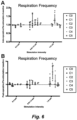
- 230000036391 respiratory frequency Effects 0.000 description 49
- 241001465754 Metazoa Species 0.000 description 41
- 210000000273 spinal nerve root Anatomy 0.000 description 34
- 230000001965 increasing effect Effects 0.000 description 23
- 210000005036 nerve Anatomy 0.000 description 23
- 230000008859 change Effects 0.000 description 22
- 230000000670 limiting effect Effects 0.000 description 22
- 230000000694 effects Effects 0.000 description 20
- 230000033001 locomotion Effects 0.000 description 20
- 210000003491 skin Anatomy 0.000 description 20
- 241000699670 Mus sp. Species 0.000 description 18
- 210000002569 neuron Anatomy 0.000 description 17
- 230000033764 rhythmic process Effects 0.000 description 17
- 230000004936 stimulating effect Effects 0.000 description 17
- 210000001519 tissue Anatomy 0.000 description 17
- 210000003205 muscle Anatomy 0.000 description 16
- 210000000779 thoracic wall Anatomy 0.000 description 16
- 241000282412 Homo Species 0.000 description 14
- 239000008280 blood Substances 0.000 description 14
- 210000004369 blood Anatomy 0.000 description 14
- 230000007274 generation of a signal involved in cell-cell signaling Effects 0.000 description 14
- 230000036387 respiratory rate Effects 0.000 description 13
- 230000001154 acute effect Effects 0.000 description 12
- 208000020431 spinal cord injury Diseases 0.000 description 12
- 206010002091 Anaesthesia Diseases 0.000 description 11
- 208000034972 Sudden Infant Death Diseases 0.000 description 11
- 206010042440 Sudden infant death syndrome Diseases 0.000 description 11
- 230000037005 anaesthesia Effects 0.000 description 11
- 210000000038 chest Anatomy 0.000 description 11
- 229920000052 poly(p-xylylene) Polymers 0.000 description 11
- 241001269524 Dura Species 0.000 description 10
- 206010002026 amyotrophic lateral sclerosis Diseases 0.000 description 10
- 241000699666 Mus <mouse, genus> Species 0.000 description 9
- 208000029028 brain injury Diseases 0.000 description 9
- 238000003491 array Methods 0.000 description 8
- 210000004556 brain Anatomy 0.000 description 8
- 238000002474 experimental method Methods 0.000 description 8
- 230000003434 inspiratory effect Effects 0.000 description 8
- 238000004458 analytical method Methods 0.000 description 7
- QVGXLLKOCUKJST-UHFFFAOYSA-N atomic oxygen Chemical compound [O] QVGXLLKOCUKJST-UHFFFAOYSA-N 0.000 description 7
- 230000001276 controlling effect Effects 0.000 description 7
- 239000000835 fiber Substances 0.000 description 7
- 238000000338 in vitro Methods 0.000 description 7
- 238000003780 insertion Methods 0.000 description 7
- 230000037431 insertion Effects 0.000 description 7
- 238000002684 laminectomy Methods 0.000 description 7
- 239000000463 material Substances 0.000 description 7
- 230000007246 mechanism Effects 0.000 description 7
- 229910052751 metal Inorganic materials 0.000 description 7
- 239000002184 metal Substances 0.000 description 7
- 239000001301 oxygen Substances 0.000 description 7
- 229910052760 oxygen Inorganic materials 0.000 description 7
- 238000002360 preparation method Methods 0.000 description 7
- 230000001953 sensory effect Effects 0.000 description 7
- 210000000434 stratum corneum Anatomy 0.000 description 7
- 238000001356 surgical procedure Methods 0.000 description 7
- 230000002459 sustained effect Effects 0.000 description 7
- 239000003826 tablet Substances 0.000 description 7
- 238000012360 testing method Methods 0.000 description 7
- 208000032319 Primary lateral sclerosis Diseases 0.000 description 6
- 206010046298 Upper motor neurone lesion Diseases 0.000 description 6
- 230000003247 decreasing effect Effects 0.000 description 6
- 239000000499 gel Substances 0.000 description 6
- 208000014674 injury Diseases 0.000 description 6
- 201000010901 lateral sclerosis Diseases 0.000 description 6
- 210000004705 lumbosacral region Anatomy 0.000 description 6
- 208000005264 motor neuron disease Diseases 0.000 description 6
- 208000015122 neurodegenerative disease Diseases 0.000 description 6
- 230000036961 partial effect Effects 0.000 description 6
- 201000004193 respiratory failure Diseases 0.000 description 6
- 208000003870 Drug Overdose Diseases 0.000 description 5
- 206010033296 Overdoses Diseases 0.000 description 5
- XUIMIQQOPSSXEZ-UHFFFAOYSA-N Silicon Chemical compound [Si] XUIMIQQOPSSXEZ-UHFFFAOYSA-N 0.000 description 5
- 230000004913 activation Effects 0.000 description 5
- 206010001053 acute respiratory failure Diseases 0.000 description 5
- 239000005557 antagonist Substances 0.000 description 5
- 230000000994 depressogenic effect Effects 0.000 description 5
- 231100000725 drug overdose Toxicity 0.000 description 5
- 230000009977 dual effect Effects 0.000 description 5
- 239000004744 fabric Substances 0.000 description 5
- 238000002513 implantation Methods 0.000 description 5
- 230000000302 ischemic effect Effects 0.000 description 5
- 238000012423 maintenance Methods 0.000 description 5
- 108020003175 receptors Proteins 0.000 description 5
- 102000005962 receptors Human genes 0.000 description 5
- 239000003169 respiratory stimulant agent Substances 0.000 description 5
- 229910052710 silicon Inorganic materials 0.000 description 5
- 239000010703 silicon Substances 0.000 description 5
- 230000002269 spontaneous effect Effects 0.000 description 5
- 239000004753 textile Substances 0.000 description 5
- 206010066131 Congenital central hypoventilation syndrome Diseases 0.000 description 4
- 206010013142 Disinhibition Diseases 0.000 description 4
- 102000001554 Hemoglobins Human genes 0.000 description 4
- 108010054147 Hemoglobins Proteins 0.000 description 4
- 238000013459 approach Methods 0.000 description 4
- 230000002051 biphasic effect Effects 0.000 description 4
- 201000010099 disease Diseases 0.000 description 4
- 208000037265 diseases, disorders, signs and symptoms Diseases 0.000 description 4
- 238000009826 distribution Methods 0.000 description 4
- 230000005684 electric field Effects 0.000 description 4
- 239000000017 hydrogel Substances 0.000 description 4
- 239000007943 implant Substances 0.000 description 4
- 210000001153 interneuron Anatomy 0.000 description 4
- 230000004199 lung function Effects 0.000 description 4
- 210000002161 motor neuron Anatomy 0.000 description 4
- 230000004007 neuromodulation Effects 0.000 description 4
- 239000002831 pharmacologic agent Substances 0.000 description 4
- 210000003105 phrenic nerve Anatomy 0.000 description 4
- BASFCYQUMIYNBI-UHFFFAOYSA-N platinum Chemical compound [Pt] BASFCYQUMIYNBI-UHFFFAOYSA-N 0.000 description 4
- 230000001020 rhythmical effect Effects 0.000 description 4
- 210000002538 spinal trigeminal nucleus Anatomy 0.000 description 4
- 239000000758 substrate Substances 0.000 description 4
- 230000008733 trauma Effects 0.000 description 4
- 102100036321 5-hydroxytryptamine receptor 2A Human genes 0.000 description 3
- 208000024827 Alzheimer disease Diseases 0.000 description 3
- 208000014094 Dystonic disease Diseases 0.000 description 3
- 208000023105 Huntington disease Diseases 0.000 description 3
- 206010021143 Hypoxia Diseases 0.000 description 3
- 241000124008 Mammalia Species 0.000 description 3
- 208000018737 Parkinson disease Diseases 0.000 description 3
- 208000027418 Wounds and injury Diseases 0.000 description 3
- VREFGVBLTWBCJP-UHFFFAOYSA-N alprazolam Chemical compound C12=CC(Cl)=CC=C2N2C(C)=NN=C2CN=C1C1=CC=CC=C1 VREFGVBLTWBCJP-UHFFFAOYSA-N 0.000 description 3
- 230000033228 biological regulation Effects 0.000 description 3
- 210000004204 blood vessel Anatomy 0.000 description 3
- 210000000988 bone and bone Anatomy 0.000 description 3
- 239000003990 capacitor Substances 0.000 description 3
- 206010008129 cerebral palsy Diseases 0.000 description 3
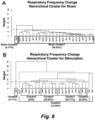
- 238000007621 cluster analysis Methods 0.000 description 3
- 238000000576 coating method Methods 0.000 description 3
- 230000001010 compromised effect Effects 0.000 description 3
- 230000006378 damage Effects 0.000 description 3
- 230000007423 decrease Effects 0.000 description 3
- 208000010118 dystonia Diseases 0.000 description 3
- 210000000624 ear auricle Anatomy 0.000 description 3
- 238000005516 engineering process Methods 0.000 description 3
- 239000007789 gas Substances 0.000 description 3
- 230000002990 hypoglossal effect Effects 0.000 description 3
- 230000001939 inductive effect Effects 0.000 description 3
- 238000004519 manufacturing process Methods 0.000 description 3
- 238000005259 measurement Methods 0.000 description 3
- 238000012544 monitoring process Methods 0.000 description 3
- 206010033675 panniculitis Diseases 0.000 description 3
- 230000035515 penetration Effects 0.000 description 3
- 230000002093 peripheral effect Effects 0.000 description 3
- 230000001830 phrenic effect Effects 0.000 description 3
- 210000001034 respiratory center Anatomy 0.000 description 3
- 239000007787 solid Substances 0.000 description 3
- 210000004304 subcutaneous tissue Anatomy 0.000 description 3
- 238000002627 tracheal intubation Methods 0.000 description 3
- 238000004804 winding Methods 0.000 description 3
- 101710138091 5-hydroxytryptamine receptor 2A Proteins 0.000 description 2
- 206010001052 Acute respiratory distress syndrome Diseases 0.000 description 2
- 206010001497 Agitation Diseases 0.000 description 2
- 206010001605 Alcohol poisoning Diseases 0.000 description 2
- OKTJSMMVPCPJKN-UHFFFAOYSA-N Carbon Chemical compound [C] OKTJSMMVPCPJKN-UHFFFAOYSA-N 0.000 description 2
- CURLTUGMZLYLDI-UHFFFAOYSA-N Carbon dioxide Chemical compound O=C=O CURLTUGMZLYLDI-UHFFFAOYSA-N 0.000 description 2
- 229920001651 Cyanoacrylate Polymers 0.000 description 2
- 241000282326 Felis catus Species 0.000 description 2
- 208000010496 Heart Arrest Diseases 0.000 description 2
- 241000997826 Melanocetus johnsonii Species 0.000 description 2
- 206010033799 Paralysis Diseases 0.000 description 2
- BQCADISMDOOEFD-UHFFFAOYSA-N Silver Chemical compound [Ag] BQCADISMDOOEFD-UHFFFAOYSA-N 0.000 description 2
- 239000004830 Super Glue Substances 0.000 description 2
- 230000003213 activating effect Effects 0.000 description 2
- 239000000853 adhesive Substances 0.000 description 2
- 230000004075 alteration Effects 0.000 description 2
- 238000001949 anaesthesia Methods 0.000 description 2
- 238000000540 analysis of variance Methods 0.000 description 2
- 210000003484 anatomy Anatomy 0.000 description 2
- 210000003050 axon Anatomy 0.000 description 2
- 230000008901 benefit Effects 0.000 description 2
- 239000000560 biocompatible material Substances 0.000 description 2
- 229910052799 carbon Inorganic materials 0.000 description 2
- 210000004027 cell Anatomy 0.000 description 2
- 210000000170 cell membrane Anatomy 0.000 description 2
- 108091008690 chemoreceptors Proteins 0.000 description 2
- 239000011248 coating agent Substances 0.000 description 2
- 239000004020 conductor Substances 0.000 description 2
- 230000002596 correlated effect Effects 0.000 description 2
- 238000007405 data analysis Methods 0.000 description 2
- 238000013461 design Methods 0.000 description 2
- 206010013663 drug dependence Diseases 0.000 description 2
- 230000004064 dysfunction Effects 0.000 description 2
- 230000005284 excitation Effects 0.000 description 2
- 230000002964 excitative effect Effects 0.000 description 2
- 230000008713 feedback mechanism Effects 0.000 description 2
- 238000010304 firing Methods 0.000 description 2
- 210000002683 foot Anatomy 0.000 description 2
- 210000001061 forehead Anatomy 0.000 description 2
- 230000006870 function Effects 0.000 description 2
- 229910052739 hydrogen Inorganic materials 0.000 description 2
- 230000007954 hypoxia Effects 0.000 description 2
- 230000002401 inhibitory effect Effects 0.000 description 2
- 230000003993 interaction Effects 0.000 description 2
- 230000003585 interneuronal effect Effects 0.000 description 2
- 230000003902 lesion Effects 0.000 description 2
- 230000007774 longterm Effects 0.000 description 2
- 230000007659 motor function Effects 0.000 description 2
- 210000004126 nerve fiber Anatomy 0.000 description 2
- 210000004498 neuroglial cell Anatomy 0.000 description 2
- 230000002232 neuromuscular Effects 0.000 description 2
- 230000003287 optical effect Effects 0.000 description 2
- 210000000056 organ Anatomy 0.000 description 2
- 230000036407 pain Effects 0.000 description 2
- 230000002085 persistent effect Effects 0.000 description 2
- 230000001766 physiological effect Effects 0.000 description 2
- 229910052697 platinum Inorganic materials 0.000 description 2
- 229920000642 polymer Polymers 0.000 description 2
- 230000008569 process Effects 0.000 description 2
- 210000003504 pulmonary stretch receptor Anatomy 0.000 description 2
- 230000009467 reduction Effects 0.000 description 2
- 230000002829 reductive effect Effects 0.000 description 2
- 238000011160 research Methods 0.000 description 2
- 238000002271 resection Methods 0.000 description 2
- 210000003019 respiratory muscle Anatomy 0.000 description 2
- 239000000523 sample Substances 0.000 description 2
- 238000000926 separation method Methods 0.000 description 2
- QZAYGJVTTNCVMB-UHFFFAOYSA-N serotonin Chemical compound C1=C(O)C=C2C(CCN)=CNC2=C1 QZAYGJVTTNCVMB-UHFFFAOYSA-N 0.000 description 2
- 229910052709 silver Inorganic materials 0.000 description 2
- 239000004332 silver Substances 0.000 description 2
- 231100000075 skin burn Toxicity 0.000 description 2
- 210000003625 skull Anatomy 0.000 description 2
- 230000000392 somatic effect Effects 0.000 description 2
- 210000003594 spinal ganglia Anatomy 0.000 description 2
- 210000005250 spinal neuron Anatomy 0.000 description 2
- 208000011117 substance-related disease Diseases 0.000 description 2
- 230000001225 therapeutic effect Effects 0.000 description 2
- 238000002560 therapeutic procedure Methods 0.000 description 2
- 230000000472 traumatic effect Effects 0.000 description 2
- 238000010200 validation analysis Methods 0.000 description 2
- XLYOFNOQVPJJNP-UHFFFAOYSA-N water Substances O XLYOFNOQVPJJNP-UHFFFAOYSA-N 0.000 description 2
- GUHKMHMGKKRFDT-UHFFFAOYSA-N 1785-64-4 Chemical compound C1CC(=C(F)C=2F)C(F)=C(F)C=2CCC2=C(F)C(F)=C1C(F)=C2F GUHKMHMGKKRFDT-UHFFFAOYSA-N 0.000 description 1
- SMZOUWXMTYCWNB-UHFFFAOYSA-N 2-(2-methoxy-5-methylphenyl)ethanamine Chemical compound COC1=CC=C(C)C=C1CCN SMZOUWXMTYCWNB-UHFFFAOYSA-N 0.000 description 1
- NIXOWILDQLNWCW-UHFFFAOYSA-N 2-Propenoic acid Natural products OC(=O)C=C NIXOWILDQLNWCW-UHFFFAOYSA-N 0.000 description 1
- VRBFTYUMFJWSJY-UHFFFAOYSA-N 28804-46-8 Chemical compound ClC1CC(C=C2)=CC=C2C(Cl)CC2=CC=C1C=C2 VRBFTYUMFJWSJY-UHFFFAOYSA-N 0.000 description 1
- 108091005477 5-HT3 receptors Proteins 0.000 description 1
- 108091005436 5-HT7 receptors Proteins 0.000 description 1
- 102100022738 5-hydroxytryptamine receptor 1A Human genes 0.000 description 1
- 206010069632 Bladder dysfunction Diseases 0.000 description 1
- 241000282472 Canis lupus familiaris Species 0.000 description 1
- VYZAMTAEIAYCRO-UHFFFAOYSA-N Chromium Chemical compound [Cr] VYZAMTAEIAYCRO-UHFFFAOYSA-N 0.000 description 1
- RYGMFSIKBFXOCR-UHFFFAOYSA-N Copper Chemical compound [Cu] RYGMFSIKBFXOCR-UHFFFAOYSA-N 0.000 description 1
- 229920000742 Cotton Polymers 0.000 description 1
- 101150049660 DRD2 gene Proteins 0.000 description 1
- 206010013647 Drowning Diseases 0.000 description 1
- 206010013975 Dyspnoeas Diseases 0.000 description 1
- 241000283073 Equus caballus Species 0.000 description 1
- 241000282324 Felis Species 0.000 description 1
- 101150015707 HTR1A gene Proteins 0.000 description 1
- 101150104779 HTR2A gene Proteins 0.000 description 1
- PIWKPBJCKXDKJR-UHFFFAOYSA-N Isoflurane Chemical compound FC(F)OC(Cl)C(F)(F)F PIWKPBJCKXDKJR-UHFFFAOYSA-N 0.000 description 1
- 206010061296 Motor dysfunction Diseases 0.000 description 1
- WHNWPMSKXPGLAX-UHFFFAOYSA-N N-Vinyl-2-pyrrolidone Chemical compound C=CN1CCCC1=O WHNWPMSKXPGLAX-UHFFFAOYSA-N 0.000 description 1
- 239000004642 Polyimide Substances 0.000 description 1
- 208000004756 Respiratory Insufficiency Diseases 0.000 description 1
- 206010038669 Respiratory arrest Diseases 0.000 description 1
- 241000283984 Rodentia Species 0.000 description 1
- 206010039897 Sedation Diseases 0.000 description 1
- 201000001880 Sexual dysfunction Diseases 0.000 description 1
- 229910021607 Silver chloride Inorganic materials 0.000 description 1
- 208000020339 Spinal injury Diseases 0.000 description 1
- 208000006011 Stroke Diseases 0.000 description 1
- RTAQQCXQSZGOHL-UHFFFAOYSA-N Titanium Chemical compound [Ti] RTAQQCXQSZGOHL-UHFFFAOYSA-N 0.000 description 1
- 208000030886 Traumatic Brain injury Diseases 0.000 description 1
- 230000003187 abdominal effect Effects 0.000 description 1
- 230000009471 action Effects 0.000 description 1
- 230000001464 adherent effect Effects 0.000 description 1
- 230000001070 adhesive effect Effects 0.000 description 1
- 210000000577 adipose tissue Anatomy 0.000 description 1
- 239000000951 adrenergic alpha-1 receptor antagonist Substances 0.000 description 1
- 239000000670 adrenergic alpha-2 receptor antagonist Substances 0.000 description 1
- 229910045601 alloy Inorganic materials 0.000 description 1
- 239000000956 alloy Substances 0.000 description 1
- 230000009286 beneficial effect Effects 0.000 description 1
- 230000036760 body temperature Effects 0.000 description 1
- 229910002092 carbon dioxide Inorganic materials 0.000 description 1
- 239000001569 carbon dioxide Substances 0.000 description 1
- 230000000747 cardiac effect Effects 0.000 description 1
- 230000002490 cerebral effect Effects 0.000 description 1
- 210000004889 cervical nerve Anatomy 0.000 description 1
- 229910052804 chromium Inorganic materials 0.000 description 1
- 239000011651 chromium Substances 0.000 description 1
- 230000001684 chronic effect Effects 0.000 description 1
- 238000004891 communication Methods 0.000 description 1
- 230000008602 contraction Effects 0.000 description 1
- 229920001577 copolymer Polymers 0.000 description 1
- 229910052802 copper Inorganic materials 0.000 description 1
- 239000010949 copper Substances 0.000 description 1
- 239000006071 cream Substances 0.000 description 1
- 238000013480 data collection Methods 0.000 description 1
- 238000001514 detection method Methods 0.000 description 1
- 239000004205 dimethyl polysiloxane Substances 0.000 description 1
- 235000013870 dimethyl polysiloxane Nutrition 0.000 description 1
- 230000003292 diminished effect Effects 0.000 description 1
- 238000001035 drying Methods 0.000 description 1
- 206010015037 epilepsy Diseases 0.000 description 1
- 230000000763 evoking effect Effects 0.000 description 1
- 230000004907 flux Effects 0.000 description 1
- PCHJSUWPFVWCPO-UHFFFAOYSA-N gold Chemical compound [Au] PCHJSUWPFVWCPO-UHFFFAOYSA-N 0.000 description 1
- 229910052737 gold Inorganic materials 0.000 description 1
- 239000010931 gold Substances 0.000 description 1
- 210000004884 grey matter Anatomy 0.000 description 1
- LNEPOXFFQSENCJ-UHFFFAOYSA-N haloperidol Chemical compound C1CC(O)(C=2C=CC(Cl)=CC=2)CCN1CCCC(=O)C1=CC=C(F)C=C1 LNEPOXFFQSENCJ-UHFFFAOYSA-N 0.000 description 1
- 230000036541 health Effects 0.000 description 1
- 238000007417 hierarchical cluster analysis Methods 0.000 description 1
- 230000001771 impaired effect Effects 0.000 description 1
- 230000001976 improved effect Effects 0.000 description 1
- 230000006872 improvement Effects 0.000 description 1
- 238000001727 in vivo Methods 0.000 description 1
- 208000015181 infectious disease Diseases 0.000 description 1
- 238000002347 injection Methods 0.000 description 1
- 239000007924 injection Substances 0.000 description 1
- 230000010354 integration Effects 0.000 description 1
- 238000001990 intravenous administration Methods 0.000 description 1
- 210000000011 invertebrate ventral nerve cord Anatomy 0.000 description 1
- 229910052741 iridium Inorganic materials 0.000 description 1
- GKOZUEZYRPOHIO-UHFFFAOYSA-N iridium atom Chemical compound [Ir] GKOZUEZYRPOHIO-UHFFFAOYSA-N 0.000 description 1
- 229960002725 isoflurane Drugs 0.000 description 1
- 210000004749 ligamentum flavum Anatomy 0.000 description 1
- 230000031700 light absorption Effects 0.000 description 1
- 239000011159 matrix material Substances 0.000 description 1
- 230000028161 membrane depolarization Effects 0.000 description 1
- 150000002739 metals Chemical class 0.000 description 1
- MYWUZJCMWCOHBA-VIFPVBQESA-N methamphetamine Chemical compound CN[C@@H](C)CC1=CC=CC=C1 MYWUZJCMWCOHBA-VIFPVBQESA-N 0.000 description 1
- VNWKTOKETHGBQD-UHFFFAOYSA-N methane Chemical compound C VNWKTOKETHGBQD-UHFFFAOYSA-N 0.000 description 1
- 230000003278 mimic effect Effects 0.000 description 1
- 239000002480 mineral oil Substances 0.000 description 1
- 235000010446 mineral oil Nutrition 0.000 description 1
- 238000012986 modification Methods 0.000 description 1
- 230000004048 modification Effects 0.000 description 1
- 230000001095 motoneuron effect Effects 0.000 description 1
- 210000000337 motor cortex Anatomy 0.000 description 1
- 201000006417 multiple sclerosis Diseases 0.000 description 1
- 230000004118 muscle contraction Effects 0.000 description 1
- 230000007383 nerve stimulation Effects 0.000 description 1
- 210000000944 nerve tissue Anatomy 0.000 description 1
- 230000004766 neurogenesis Effects 0.000 description 1
- 235000001968 nicotinic acid Nutrition 0.000 description 1
- CXQXSVUQTKDNFP-UHFFFAOYSA-N octamethyltrisiloxane Chemical compound C[Si](C)(C)O[Si](C)(C)O[Si](C)(C)C CXQXSVUQTKDNFP-UHFFFAOYSA-N 0.000 description 1
- 229940127240 opiate Drugs 0.000 description 1
- 238000005457 optimization Methods 0.000 description 1
- 210000002741 palatine tonsil Anatomy 0.000 description 1
- 239000002245 particle Substances 0.000 description 1
- 244000144985 peep Species 0.000 description 1
- 210000000578 peripheral nerve Anatomy 0.000 description 1
- 230000035699 permeability Effects 0.000 description 1
- 230000002688 persistence Effects 0.000 description 1
- 230000035790 physiological processes and functions Effects 0.000 description 1
- 238000004987 plasma desorption mass spectroscopy Methods 0.000 description 1
- 229920000435 poly(dimethylsiloxane) Polymers 0.000 description 1
- 229920001721 polyimide Polymers 0.000 description 1
- 238000006116 polymerization reaction Methods 0.000 description 1
- 230000005855 radiation Effects 0.000 description 1
- 229940044601 receptor agonist Drugs 0.000 description 1
- 239000000018 receptor agonist Substances 0.000 description 1
- 229940044551 receptor antagonist Drugs 0.000 description 1
- 239000002464 receptor antagonist Substances 0.000 description 1
- 230000008439 repair process Effects 0.000 description 1
- 230000003252 repetitive effect Effects 0.000 description 1
- 230000019254 respiratory burst Effects 0.000 description 1
- 210000002345 respiratory system Anatomy 0.000 description 1
- 230000036390 resting membrane potential Effects 0.000 description 1
- 230000002207 retinal effect Effects 0.000 description 1
- 230000036280 sedation Effects 0.000 description 1
- 229940076279 serotonin Drugs 0.000 description 1
- 239000003727 serotonin 1A antagonist Substances 0.000 description 1
- 239000000198 serotonin 5-HT3 receptor agonist Substances 0.000 description 1
- 239000003369 serotonin 5-HT3 receptor antagonist Substances 0.000 description 1
- 239000000952 serotonin receptor agonist Substances 0.000 description 1
- 231100000872 sexual dysfunction Toxicity 0.000 description 1
- 238000007493 shaping process Methods 0.000 description 1
- HKZLPVFGJNLROG-UHFFFAOYSA-M silver monochloride Chemical compound [Cl-].[Ag+] HKZLPVFGJNLROG-UHFFFAOYSA-M 0.000 description 1
- 239000010935 stainless steel Substances 0.000 description 1
- 229910001220 stainless steel Inorganic materials 0.000 description 1
- 239000000126 substance Substances 0.000 description 1
- 208000024891 symptom Diseases 0.000 description 1
- 230000001360 synchronised effect Effects 0.000 description 1
- 230000009897 systematic effect Effects 0.000 description 1
- 210000003448 thoracic nerve Anatomy 0.000 description 1
- 230000036962 time dependent Effects 0.000 description 1
- 229910052719 titanium Inorganic materials 0.000 description 1
- 239000010936 titanium Substances 0.000 description 1
- 230000001256 tonic effect Effects 0.000 description 1
- 210000005062 tracheal ring Anatomy 0.000 description 1
- 238000011491 transcranial magnetic stimulation Methods 0.000 description 1
- 230000001052 transient effect Effects 0.000 description 1
- 238000013519 translation Methods 0.000 description 1
- 230000009529 traumatic brain injury Effects 0.000 description 1
- WFKWXMTUELFFGS-UHFFFAOYSA-N tungsten Chemical compound [W] WFKWXMTUELFFGS-UHFFFAOYSA-N 0.000 description 1
- 229910052721 tungsten Inorganic materials 0.000 description 1
- 239000010937 tungsten Substances 0.000 description 1
- 210000004760 visceral afferent Anatomy 0.000 description 1
- 230000009278 visceral effect Effects 0.000 description 1
- 238000005406 washing Methods 0.000 description 1
- 239000003643 water by type Substances 0.000 description 1
- 210000004885 white matter Anatomy 0.000 description 1
Images


Classifications
-
- A—HUMAN NECESSITIES
- A61—MEDICAL OR VETERINARY SCIENCE; HYGIENE
- A61B—DIAGNOSIS; SURGERY; IDENTIFICATION
- A61B5/00—Measuring for diagnostic purposes; Identification of persons
- A61B5/08—Detecting, measuring or recording devices for evaluating the respiratory organs
- A61B5/0816—Measuring devices for examining respiratory frequency
-
- A—HUMAN NECESSITIES
- A61—MEDICAL OR VETERINARY SCIENCE; HYGIENE
- A61N—ELECTROTHERAPY; MAGNETOTHERAPY; RADIATION THERAPY; ULTRASOUND THERAPY
- A61N1/00—Electrotherapy; Circuits therefor
- A61N1/18—Applying electric currents by contact electrodes
- A61N1/32—Applying electric currents by contact electrodes alternating or intermittent currents
- A61N1/36—Applying electric currents by contact electrodes alternating or intermittent currents for stimulation
- A61N1/3605—Implantable neurostimulators for stimulating central or peripheral nerve system
- A61N1/3606—Implantable neurostimulators for stimulating central or peripheral nerve system adapted for a particular treatment
- A61N1/3611—Respiration control
-
- A—HUMAN NECESSITIES
- A61—MEDICAL OR VETERINARY SCIENCE; HYGIENE
- A61B—DIAGNOSIS; SURGERY; IDENTIFICATION
- A61B5/00—Measuring for diagnostic purposes; Identification of persons
- A61B5/48—Other medical applications
- A61B5/4836—Diagnosis combined with treatment in closed-loop systems or methods
- A61B5/4839—Diagnosis combined with treatment in closed-loop systems or methods combined with drug delivery
-
- A—HUMAN NECESSITIES
- A61—MEDICAL OR VETERINARY SCIENCE; HYGIENE
- A61N—ELECTROTHERAPY; MAGNETOTHERAPY; RADIATION THERAPY; ULTRASOUND THERAPY
- A61N1/00—Electrotherapy; Circuits therefor
- A61N1/02—Details
- A61N1/04—Electrodes
- A61N1/0404—Electrodes for external use
- A61N1/0408—Use-related aspects
- A61N1/0456—Specially adapted for transcutaneous electrical nerve stimulation [TENS]
-
- A—HUMAN NECESSITIES
- A61—MEDICAL OR VETERINARY SCIENCE; HYGIENE
- A61N—ELECTROTHERAPY; MAGNETOTHERAPY; RADIATION THERAPY; ULTRASOUND THERAPY
- A61N1/00—Electrotherapy; Circuits therefor
- A61N1/02—Details
- A61N1/04—Electrodes
- A61N1/05—Electrodes for implantation or insertion into the body, e.g. heart electrode
- A61N1/0551—Spinal or peripheral nerve electrodes
-
- A—HUMAN NECESSITIES
- A61—MEDICAL OR VETERINARY SCIENCE; HYGIENE
- A61N—ELECTROTHERAPY; MAGNETOTHERAPY; RADIATION THERAPY; ULTRASOUND THERAPY
- A61N1/00—Electrotherapy; Circuits therefor
- A61N1/18—Applying electric currents by contact electrodes
- A61N1/32—Applying electric currents by contact electrodes alternating or intermittent currents
- A61N1/36—Applying electric currents by contact electrodes alternating or intermittent currents for stimulation
- A61N1/3601—Applying electric currents by contact electrodes alternating or intermittent currents for stimulation of respiratory organs
-
- A—HUMAN NECESSITIES
- A61—MEDICAL OR VETERINARY SCIENCE; HYGIENE
- A61N—ELECTROTHERAPY; MAGNETOTHERAPY; RADIATION THERAPY; ULTRASOUND THERAPY
- A61N1/00—Electrotherapy; Circuits therefor
- A61N1/18—Applying electric currents by contact electrodes
- A61N1/32—Applying electric currents by contact electrodes alternating or intermittent currents
- A61N1/36—Applying electric currents by contact electrodes alternating or intermittent currents for stimulation
- A61N1/36014—External stimulators, e.g. with patch electrodes
- A61N1/36017—External stimulators, e.g. with patch electrodes with leads or electrodes penetrating the skin
-
- A—HUMAN NECESSITIES
- A61—MEDICAL OR VETERINARY SCIENCE; HYGIENE
- A61N—ELECTROTHERAPY; MAGNETOTHERAPY; RADIATION THERAPY; ULTRASOUND THERAPY
- A61N1/00—Electrotherapy; Circuits therefor
- A61N1/18—Applying electric currents by contact electrodes
- A61N1/32—Applying electric currents by contact electrodes alternating or intermittent currents
- A61N1/36—Applying electric currents by contact electrodes alternating or intermittent currents for stimulation
- A61N1/36014—External stimulators, e.g. with patch electrodes
- A61N1/3603—Control systems
- A61N1/36031—Control systems using physiological parameters for adjustment
-
- A—HUMAN NECESSITIES
- A61—MEDICAL OR VETERINARY SCIENCE; HYGIENE
- A61N—ELECTROTHERAPY; MAGNETOTHERAPY; RADIATION THERAPY; ULTRASOUND THERAPY
- A61N1/00—Electrotherapy; Circuits therefor
- A61N1/18—Applying electric currents by contact electrodes
- A61N1/32—Applying electric currents by contact electrodes alternating or intermittent currents
- A61N1/36—Applying electric currents by contact electrodes alternating or intermittent currents for stimulation
- A61N1/36014—External stimulators, e.g. with patch electrodes
- A61N1/3603—Control systems
- A61N1/36034—Control systems specified by the stimulation parameters
-
- A—HUMAN NECESSITIES
- A61—MEDICAL OR VETERINARY SCIENCE; HYGIENE
- A61N—ELECTROTHERAPY; MAGNETOTHERAPY; RADIATION THERAPY; ULTRASOUND THERAPY
- A61N1/00—Electrotherapy; Circuits therefor
- A61N1/18—Applying electric currents by contact electrodes
- A61N1/32—Applying electric currents by contact electrodes alternating or intermittent currents
- A61N1/36—Applying electric currents by contact electrodes alternating or intermittent currents for stimulation
- A61N1/3605—Implantable neurostimulators for stimulating central or peripheral nerve system
- A61N1/3606—Implantable neurostimulators for stimulating central or peripheral nerve system adapted for a particular treatment
- A61N1/36062—Spinal stimulation
-
- A—HUMAN NECESSITIES
- A61—MEDICAL OR VETERINARY SCIENCE; HYGIENE
- A61N—ELECTROTHERAPY; MAGNETOTHERAPY; RADIATION THERAPY; ULTRASOUND THERAPY
- A61N1/00—Electrotherapy; Circuits therefor
- A61N1/18—Applying electric currents by contact electrodes
- A61N1/32—Applying electric currents by contact electrodes alternating or intermittent currents
- A61N1/36—Applying electric currents by contact electrodes alternating or intermittent currents for stimulation
- A61N1/3605—Implantable neurostimulators for stimulating central or peripheral nerve system
- A61N1/36128—Control systems
- A61N1/36132—Control systems using patient feedback
-
- A—HUMAN NECESSITIES
- A61—MEDICAL OR VETERINARY SCIENCE; HYGIENE
- A61N—ELECTROTHERAPY; MAGNETOTHERAPY; RADIATION THERAPY; ULTRASOUND THERAPY
- A61N1/00—Electrotherapy; Circuits therefor
- A61N1/18—Applying electric currents by contact electrodes
- A61N1/32—Applying electric currents by contact electrodes alternating or intermittent currents
- A61N1/36—Applying electric currents by contact electrodes alternating or intermittent currents for stimulation
- A61N1/3605—Implantable neurostimulators for stimulating central or peripheral nerve system
- A61N1/36128—Control systems
- A61N1/36135—Control systems using physiological parameters
- A61N1/36139—Control systems using physiological parameters with automatic adjustment
-
- A—HUMAN NECESSITIES
- A61—MEDICAL OR VETERINARY SCIENCE; HYGIENE
- A61N—ELECTROTHERAPY; MAGNETOTHERAPY; RADIATION THERAPY; ULTRASOUND THERAPY
- A61N1/00—Electrotherapy; Circuits therefor
- A61N1/18—Applying electric currents by contact electrodes
- A61N1/32—Applying electric currents by contact electrodes alternating or intermittent currents
- A61N1/36—Applying electric currents by contact electrodes alternating or intermittent currents for stimulation
- A61N1/3605—Implantable neurostimulators for stimulating central or peripheral nerve system
- A61N1/36128—Control systems
- A61N1/36146—Control systems specified by the stimulation parameters
- A61N1/3615—Intensity
-
- A—HUMAN NECESSITIES
- A61—MEDICAL OR VETERINARY SCIENCE; HYGIENE
- A61N—ELECTROTHERAPY; MAGNETOTHERAPY; RADIATION THERAPY; ULTRASOUND THERAPY
- A61N1/00—Electrotherapy; Circuits therefor
- A61N1/18—Applying electric currents by contact electrodes
- A61N1/32—Applying electric currents by contact electrodes alternating or intermittent currents
- A61N1/36—Applying electric currents by contact electrodes alternating or intermittent currents for stimulation
- A61N1/3605—Implantable neurostimulators for stimulating central or peripheral nerve system
- A61N1/36128—Control systems
- A61N1/36189—Control systems using modulation techniques
- A61N1/36192—Amplitude modulation
-
- A—HUMAN NECESSITIES
- A61—MEDICAL OR VETERINARY SCIENCE; HYGIENE
- A61N—ELECTROTHERAPY; MAGNETOTHERAPY; RADIATION THERAPY; ULTRASOUND THERAPY
- A61N1/00—Electrotherapy; Circuits therefor
- A61N1/18—Applying electric currents by contact electrodes
- A61N1/32—Applying electric currents by contact electrodes alternating or intermittent currents
- A61N1/36—Applying electric currents by contact electrodes alternating or intermittent currents for stimulation
- A61N1/3605—Implantable neurostimulators for stimulating central or peripheral nerve system
- A61N1/36128—Control systems
- A61N1/36189—Control systems using modulation techniques
- A61N1/36196—Frequency modulation
-
- A—HUMAN NECESSITIES
- A61—MEDICAL OR VETERINARY SCIENCE; HYGIENE
- A61N—ELECTROTHERAPY; MAGNETOTHERAPY; RADIATION THERAPY; ULTRASOUND THERAPY
- A61N2/00—Magnetotherapy
- A61N2/004—Magnetotherapy specially adapted for a specific therapy
- A61N2/006—Magnetotherapy specially adapted for a specific therapy for magnetic stimulation of nerve tissue
-
- A—HUMAN NECESSITIES
- A61—MEDICAL OR VETERINARY SCIENCE; HYGIENE
- A61N—ELECTROTHERAPY; MAGNETOTHERAPY; RADIATION THERAPY; ULTRASOUND THERAPY
- A61N1/00—Electrotherapy; Circuits therefor
- A61N1/02—Details
- A61N1/04—Electrodes
- A61N1/05—Electrodes for implantation or insertion into the body, e.g. heart electrode
- A61N1/0502—Skin piercing electrodes
-
- A—HUMAN NECESSITIES
- A61—MEDICAL OR VETERINARY SCIENCE; HYGIENE
- A61N—ELECTROTHERAPY; MAGNETOTHERAPY; RADIATION THERAPY; ULTRASOUND THERAPY
- A61N1/00—Electrotherapy; Circuits therefor
- A61N1/02—Details
- A61N1/04—Electrodes
- A61N1/05—Electrodes for implantation or insertion into the body, e.g. heart electrode
- A61N1/0551—Spinal or peripheral nerve electrodes
- A61N1/0553—Paddle shaped electrodes, e.g. for laminotomy
-
- A—HUMAN NECESSITIES
- A61—MEDICAL OR VETERINARY SCIENCE; HYGIENE
- A61N—ELECTROTHERAPY; MAGNETOTHERAPY; RADIATION THERAPY; ULTRASOUND THERAPY
- A61N1/00—Electrotherapy; Circuits therefor
- A61N1/18—Applying electric currents by contact electrodes
- A61N1/32—Applying electric currents by contact electrodes alternating or intermittent currents
- A61N1/36—Applying electric currents by contact electrodes alternating or intermittent currents for stimulation
- A61N1/3605—Implantable neurostimulators for stimulating central or peripheral nerve system
- A61N1/36128—Control systems
- A61N1/36146—Control systems specified by the stimulation parameters
- A61N1/3615—Intensity
- A61N1/36157—Current
-
- A—HUMAN NECESSITIES
- A61—MEDICAL OR VETERINARY SCIENCE; HYGIENE
- A61N—ELECTROTHERAPY; MAGNETOTHERAPY; RADIATION THERAPY; ULTRASOUND THERAPY
- A61N1/00—Electrotherapy; Circuits therefor
- A61N1/18—Applying electric currents by contact electrodes
- A61N1/32—Applying electric currents by contact electrodes alternating or intermittent currents
- A61N1/36—Applying electric currents by contact electrodes alternating or intermittent currents for stimulation
- A61N1/3605—Implantable neurostimulators for stimulating central or peripheral nerve system
- A61N1/36128—Control systems
- A61N1/36146—Control systems specified by the stimulation parameters
- A61N1/36167—Timing, e.g. stimulation onset
- A61N1/36171—Frequency
-
- A—HUMAN NECESSITIES
- A61—MEDICAL OR VETERINARY SCIENCE; HYGIENE
- A61N—ELECTROTHERAPY; MAGNETOTHERAPY; RADIATION THERAPY; ULTRASOUND THERAPY
- A61N1/00—Electrotherapy; Circuits therefor
- A61N1/18—Applying electric currents by contact electrodes
- A61N1/32—Applying electric currents by contact electrodes alternating or intermittent currents
- A61N1/36—Applying electric currents by contact electrodes alternating or intermittent currents for stimulation
- A61N1/3605—Implantable neurostimulators for stimulating central or peripheral nerve system
- A61N1/36128—Control systems
- A61N1/36146—Control systems specified by the stimulation parameters
- A61N1/36167—Timing, e.g. stimulation onset
- A61N1/36175—Pulse width or duty cycle
-
- A—HUMAN NECESSITIES
- A61—MEDICAL OR VETERINARY SCIENCE; HYGIENE
- A61N—ELECTROTHERAPY; MAGNETOTHERAPY; RADIATION THERAPY; ULTRASOUND THERAPY
- A61N2/00—Magnetotherapy
- A61N2/02—Magnetotherapy using magnetic fields produced by coils, including single turn loops or electromagnets
Definitions
- Respiration or breathing involves a complex network of circuits that is involved in central pattern generation (CPG) that spans the brainstem and cervical spinal cord to generate a respiratory rhythm.
- CPG central pattern generation
- CO 2 receptors e.g., CO 2 receptors
- lung stretch receptors naturally influence the firing pattern of the CPG.
- the respiratory rhythm is compromised, likely due to the depressed state of the CPG.
- Current technology in addressing the depressed respiratory state is to stimulate the diaphragm muscle which actively participates in inspiration by phrenic nerve stimulators. The issue with this approach is that the muscle will not react to changes in the activity state of the patient and only activates the diaphragm which participates in the inspiratory phase of respiration.
- electrical stimulation means application of an electrical signal that may be either excitatory or inhibitory to a muscle or neuron and/or to groups of neurons and/or interneurons. It will be understood that an electrical signal may be applied to one or more electrodes with one or more return electrodes.
- magnetic stimulation or means use of a varying magnetic field to induce an electrical signal, e.g., in a neuron, that may be either excitatory or inhibitory to a muscle or neuron and/or to groups of neurons and/or interneurons. It will be understood that an electrical signal may be applied to one or more electrodes with one or more return electrodes.
- epidural means situated upon the dura or in very close proximity to the dura.
- epidural stimulation refers to electrical epidural stimulation.
- transcutaneous stimulation or “transcutaneous electrical stimulation” or “cutaneous electrical stimulation” refers to electrical stimulation applied to the skin, and, as typically used herein refers to electrical stimulation applied to the skin in order to effect stimulation of the spinal cord or a region thereof.
- transcutaneous electrical spinal cord stimulation may also be referred to as “tSCS”.
- pcEmc refers to painless cutaneous electrical stimulation.
- motor complete when used with respect to a spinal cord injury indicates that there is no motor function below the lesion, (e.g ., no movement can be voluntarily induced in muscles innervated by spinal segments below the spinal lesion.
- monopolar stimulation refers to stimulation between a local electrode and a common distant return electrode.
- spinal cord stimulation includes stimulation of any spinal nervous tissue, including spinal neurons, accessory neuronal cells, nerves, nerve roots, nerve fibers, or tissues, that are associated with the spinal cord. It is contemplated that spinal cord stimulation may comprise stimulation of one or more areas associated with a cervical vertebral segment.
- spinal nervous tissue refers to nerves, neurons, neuroglial cells, glial cells, neuronal accessory cells, nerve roots, nerve fibers, nerve rootlets, parts of nerves, nerve bundles, mixed nerves, sensory fibers, motor fibers, dorsal root, ventral root, dorsal root ganglion, spinal ganglion, ventral motor root, general somatic afferent fibers, general visceral afferent fibers, general somatic efferent fibers, general visceral efferent fibers, grey matter, white matter, the dorsal column, the lateral column, and/or the ventral column associated with the spinal cord.
- Spinal nervous tissue includes "spinal nerve roots,” that comprise any one or more of the 31 pairs of nerves that emerge from the spinal cord.
- Spinal nerve roots may be cervical nerve roots, thoracic nerve roots, and lumbar nerve roots.
- spinal cord stimulation with and without selective pharmaceuticals to enable respiratory function in subjects whose ability to breath has been compromised.
- the spinal cord stimulation can be transcutaneous and/or epidural electrical stimulation and/or magnetic stimulation.
- the electrical stimulation alone or in combination with pharmaceuticals can be applied to facilitate restoration of normal breathing patterns.
- Various embodiments contemplated herein may include, but need not be limited to, one or more of the following:
- Various embodiments contemplated herein may include, but need not be limited to, one or more of the following:
- Respiration or breathing involves a complex network of circuits that is involved in central pattern generation (CPG) that spans the brainstem and cervical spinal cord to generate a respiratory rhythm.
- CPG central pattern generation
- CO 2 central and peripheral chemoreceptors
- lung stretch receptors naturally influence the firing pattern of the CPG.
- CO 2 central and peripheral chemoreceptors
- the respiratory rhythm is compromised, likely due to the depressed state of the CPG.
- methods of improving, and/or regulation, and/or restoring respiration in a subject with a respiratory deficiency typically involve neuromodulating the cervical, and/or thoracic, and/or lumbar spinal cord of the subject by administering transcutaneous stimulation to the cervical, and/or thoracic, and/or lumbar spinal cord or a region thereof at a frequency and intensity sufficient to restore respiration; and/or neuromodulating the spinal cord of the subject by administering epidural stimulation to spinal cord or a region thereof at a frequency and intensity sufficient to restore respiration; and/or neuromodulating the spinal cord of said subject with a magnetic stimulator at a frequency and intensity sufficient to restore respiration.
- the methods described herein that involve stimulation of nerve root and/or spinal cord, activate a respiratory drive that is responsive to normal feedback. It is believed more fully recapitulate normal breathing patterns. Additionally, the stimulation methods described herein can enable coughing, facilitate the opening of airways and facilitate swallowing.
- the respiratory defibrillator can be integrated into an automatic external defibrillator (AED).
- AED automatic external defibrillator
- An automated external defibrillator (AED) is a portable device that can check the heart rhythm and can send an electric shock to the heart to try to restore a normal rhythm.
- the respiratory defibrillator is integrated into an AED, the same device can be used to stimulate a heart rhythm and/or to stimulate or maintain respiration as necessary.
- the methods described herein are typically for use with a mammal (e.g ., a human, a mammal (e.g., a non-human primate, equine, feline, canus, etc. ) with a respiratory deficiency.
- a mammal e.g ., a human, a mammal (e.g., a non-human primate, equine, feline, canus, etc. ) with a respiratory deficiency.
- respiratory deficiencies can arise in a number of contexts. For example, they can arise where a subject has a brain injury and/or a spinal cord injury. In the latter context, it is believed the methods described herein will be effective where the spinal cord injury is clinically classified as motor complete or motor incomplete.
- the methods also find use in cases of ischemic brain injury (e.g. , due to stroke, drowning or other oxygen deficiency, or acute trauma).
- the methods will also find use there the respiratory deficiency is due to a neurodegenerative disorder (e.g ., Parkinson's disease, Huntington's disease, Alzheimer's disease, amyotrophic lateral sclerosis (ALS), primary lateral sclerosis (PLS), dystonia, cerebral palsy, and the like).
- a neurodegenerative disorder e.g ., Parkinson's disease, Huntington's disease, Alzheimer's disease, amyotrophic lateral sclerosis (ALS), primary lateral sclerosis (PLS), dystonia, cerebral palsy, and the like.
- the methods also find use in cases of depressed respiration due to drug overdose.
- the methods described herein can be used in conjunction with conventional respirators, e.g., to provide improved respiratory action or the methods can be used to substitute for or to wean a subject off of a traditional respirator.
- the methods, and apparatus (e.g . systems) described herein can be used to wean a subject from a ventilator.
- transcutaneous, epidural, and/or magnetic stimulation of respiration as described herein can be used to maintain respiration in a subject as they are removed from a respirator (ventilator) and/or after they have been removed from a ventilator, e.g., to facilitate respiration where there is an endogenous respiratory pattern, or to induce respiration where absent respirator or stimulation respiration would cease.
- transcutaneous electrical stimulation of the spinal cord e.g., one or more regions of the cervical spinal cord, and/or the thoracic spinal cord, and/or the lumbar spinal cord
- the epidural stimulation can be of one or more regions of the cervical spinal cord, and/or one or more regions of the thoracic spinal cord, and/or one or more regions of the lumbar spinal cord
- the location of the electrode(s) and their stimulation parameters can be important in modulating the subject's respiration rate.
- Use of surface electrode(s), as described herein, facilitates selection or alteration of particular stimulation sites as well as the application of a wide variety of stimulation parameters. Additionally, surface stimulation can be used to optimize location for an implantable electrode or electrode array for epidural stimulation.
- the methods described herein involve transcutaneous electrical stimulation of the cervical spine or a region of the cervical spine of the subject to restore or regulate respiration.
- Illustrative regions include, but are not limited to one or more regions straddling or spanning a region selected from the group consisting of C0-C1, C0-C2, C0-C3, C0-C4, C0-C5, C0-C6, C0-C7, C0-T1, C1-C1, C1-C2, C1-C3, C1-C4, C1-C7, C1-C6, C1-C7, C1-T1, C2-C2, C2-C3, C2-C4, C2-C5, C2-C6, C2-C7, C2-T1, C3-C3, C3-C4, C3-C5, C3-C6, C3-C7, C3-T1, C4-C4, C4-C5, C4-C6, C4-C7, C4-T1, C5-C5, C5-C6, C5-C7, C5-T1, C6-C4, C
- the transcutaneous stimulation is applied at a region comprising C2-C4 or a region therein. In certain embodiments the stimulation is applied at C3.
- Illustrative regions include, but are not limited to, one or more regions straddling or spanning a region selected from the group consisting of T1-T1, T1-T2, T1-T3, T1-T4, T1-T5, T1-T6, T1-T7, T1-T8, T1-T9, T1-T10, T1-T11, T1-T12, T2-T2, T2-T3, T2-T4, T2-T5, T2-T6, T2-T7, T2-T8, T2-T9, T2-T10, T2-T11, T2-T12, T3-T3, T3-T4, T3-T5, T3-T6, T3-T7, T3-T8, T3-T9, T3-T10, T3-T11, T3-T12, T4-T4, T4-T5, T4-T6, T4-T7, T4-T8, T4-T9, T4-T10, T4-T11, T4-T12, T5
- Transcutaneous electrical stimulation of the lumbar spine or a region thereof, and/or coccyx is provided.
- the methods described herein additionally or alternatively involve transcutaneous electrical stimulation of the thoracic spine (e.g ., spinal cord) or a region of the thoracic spine (spinal cord) of the subject to modulate and/or induce respiration.
- transcutaneous electrical stimulation of the thoracic spine e.g ., spinal cord
- a region of the thoracic spine spinal cord
- Illustrative regions include, but are not limited to, one or more regions straddling or spanning a region selected from the group consisting of L1-L1, L1-L2 , L1-L3, L1-L4, L1-L5, L1-S1, L1-S2, L1-S3, L1-S4, L1-S5, L2-L2 , L2-L3, L2-L4, L2-L5, L2-S1, L2-S2, L2-S3, L2-S4, L2-S5, L3-L3, L3-L4, L3-L5, L3-S1, L3-S2, L3-S3, L3-S4, L3-S5, L4-L4, L4-L5, L4-S1, L4-S2, L4-S3, L4-S4, L4-S5, L5-L5 , L5-S1, L5-S2, L5-S3, L5-S4, L5-S5, S1-S1, S1-S2, S1-S3, S1-S4, S1-S
- transcutaneous stimulation can be applied to the coccyx, e.g. , by application of one or more transcutaneous stimulation electrode(s) over the small, triangular bone at the base of the spinal column.
- the transcutaneous electrical stimulation is applied paraspinally over a lumbar region identified above or to a region thereof, e.g. , over a region spanning L2 to L3).
- the transcutaneous stimulation is at a frequency of at least about 1 Hz, or at least about 2 Hz, or at least about 3 Hz, or at least about 4 Hz, or at least about 5 Hz, or at least about 10 Hz, or at least about 20 Hz or at least about 30 Hz or at least about 40 Hz or at least about 50 Hz or at least about 60 Hz or at least about 70 Hz or at least about 80 Hz or at least about 90 Hz or at least about 100 Hz, or at least about 200 Hz, or at least about 300 Hz, or at least about 400 Hz, or at least about 500 Hz, or at least about 1 kHz, or at least about 1.5 kHz, or at least about 2 kHz, or at least about 2.5 kHz, or at least about 5 kHz, or at least about 10 kHz, or up to about 25 kHz, or up to about 50 kHz, or up to about 100 kHz.
- the transcutaneous stimulation is at a frequency ranging from about 1 Hz, or from about 2 Hz, or from about 3 Hz, or from about 4 Hz, or from about 5 Hz, or from about 10 Hz, or from about 10 Hz, or from about 10 Hz, up to about 500 Hz, or up to about 400 Hz, or up to about 300 Hz, or up to about 200 Hz up to about 100 Hz, or up to about 90 Hz, or up to about 80 Hz, or up to about 60 Hz, or up to about 40 Hz, or from about 3 Hz or from about 5 Hz up to about 80 Hz, or from about 5 Hz to about 60 Hz, or up to about 30 Hz.
- the transcutaneous stimulation is at a frequency ranging from about 20 Hz or about 30 Hz to about 90 Hz or to about 100 Hz, to initiate respiration when no respiration pattern is present. In certain embodiments the transcutaneous stimulation is at a frequency ranging from about 5 Hz or about 10 Hz up to about 90 Hz or about 100 Hz, when a respiration pattern is present.
- the transcutaneous stimulation is applied at an intensity ranging from about 5 mA or about 10 mA up to about 500 mA, or from about 5 mA or about 10 mA up to about 400 mA, or from about 5 mA or about 10 mA up to about 300 mA, or from about 5 mA or about 10 mA up to about 200 mA, or from about 5 mA or about 10 mA to up about 150 mA, or from about 5 mA or about 10 mA up to about 50 mA, or from about 5 mA or about 10 mA up to about 100 mA, or from about 5 mA or about 10 mA up to about 80 mA, or from about 5 mA or about 10 mA up to about 60 mA, or from about 5 mA or about 10 mA up to about 50 mA.
- the transcutaneous stimulation is applied stimulation comprises pulses having a width that ranges from about 100 ⁇ s up to about 1 ms or up to about 800 ⁇ s, or up to about 600 ⁇ s, or up to about 500 ⁇ s, or up to about 400 ⁇ s, or up to about 300 ⁇ s, or up to about 200 ⁇ s, or up to about 100 ⁇ s, or from about 150 ⁇ s up to about 600 ⁇ s, or from about 200 ⁇ s up to about 500 ⁇ s, or from about 200 ⁇ s up to about 400 ⁇ s.
- the transcutaneous stimulation is at a frequency, pulse width, and amplitude sufficient to restore a resting respiration rate and at least 60%, or at least 70%, or at least 80%, or at least 90% of the subjects normal tidal volume.
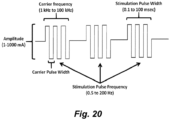
- the transcutaneous stimulation is superimposed on a high frequency carrier signal (see, e.g., Figure 20 ).
- the high frequency carrier signal ranges from about 1 kHz, or about 3 kHz, or about 5 kHz, or about 8 kHz up to about 30 kHz, or up to about 20 kHz, or up to about 15 kHz.
- the carrier signal is about 10 kHz.
- the carrier frequency amplitude ranges from about 30 mA, or about 40 mA, or about 50 mA, or about 60 mA, or about 70 mA, or about 80 mA up to about 300 mA, or up to about 200 mA, or up to about 150 mA.
- the transcutaneous stimulation is applied using any of a number different types of electrodes.
- electrodes include, but are not limited to metal plate electrodes, carbon electrodes, textile electrodes, hydrogel electrodes, needle electrodes, and the like skin ( see, e.g., Keller & Kuhn (2008) J. Automatic Control., 18(2): 34-45 ).
- the electrodes can be adhered using, e.g., tape or other adherent, or in other embodiments, the electrodes are self-adhering.
- Metal plate electrodes include, but are not limited to metal plate electrodes covered by fabric tissue.
- the metal plate is fabricated from a biocompatible material. Often stainless steel or silver/silver chloride electrodes are used.
- the fabric tissue can be cotton but is often a polymer textile material that has a certain degree of elasticity and doesn't wear out fast. Spongy materials have also been used and recommended ( see, e.g., Falk et al. (1983) N. Engl. J. Med. 309: 1166-1168 ).
- the fabric can be made conductive with water or electrode gel. It equally distributes the current over the skin in order to prevent skin burns. Care has to be taken that the electrode does not dry out.
- Self-adhesive electrodes for transcutaneous stimulation use a gel to contact a conductive member with the subject's skin (see, e.g., Keller & Kuhn (2008) J. Automatic Control., 18(2): 34-45 ).
- the electrode is typically built in a multi-layer configuration, consisting of multiple layers of hydrogel.
- the skin interface layer often includes an electrically conductive gel with relatively low peel strength for removably contacting the subject's skin. It has a wet feeling and can be removed relatively easily from the skin.
- the conductive gel is made from copolymers derived from polymerization, e.g. of acrylic acid and N-vinylpyrrolidone.
- a second hydrogel layer connects the substrate (a low resistive material like carbon rubber or a wire mesh) with the skin hydrogel layer.
- This second conductive gel layer has a relatively high peel strength that provides good adhesion to the substrate.
- carbon loaded silicon electrodes can be used (see, e.g., Baker, D. R. McNeal, L. A. Benton, B. R. Bowman, and R. L. Waters, Neuromuscular electrical stimulation: a practical guide, 3 ed. USA: Rehabilitation Engineering Program, Los Amigos Research and Education Institute, Collinso Los Amigos Medical Center, 1993 ; Nathan (1989) J. Automatic Control, 18(2): 35-45 ; Patterson & Lockwood (1993) IEEE Trans. on Neural Systems and Rehabilitation, 1: 59-62 ; and the like).
- the transcutaneous electrical stimulation can be applied via textile electrodes.
- the textile electrodes can consist of multiple fabric layers (see, e.g., Keller, et al. (2006) Conf. Proc. IEEE Eng. Med. Biol. Soc. 1: 194-197 ).
- the fabric layer facing the skin holds embroidered electrode pads made of plasma coated metallized yarn. Because of the thin metal coating (e.g., ⁇ 25 nm coating particles obtained using a plasma process) the yarn keeps its textile properties and can be embroidered. Silver coatings proved to be most stable and survived 30 washings.
- a second layer contains the embroidered electrode wiring made from the same materials and was designed such that no short circuits are produced between the pads when stitched together ( Id. ) .
- the transcutaneous electrical stimulation can be applied via one or more needle electrodes, e.g ., as described in PCT Patent Pub No: WO 2017/024276 ( PCT/US2016/045898 ).
- needle electrodes comprise one or more commonly a plurality of electrically conductive solid microprojections (or where the needles are hollow, they are closed at the tip), where the needles (microprojections) have a tip dimension/diameter small enough to facilitate penetration of the stratum corneum on the skin ( e.g., less than about 10 ⁇ m), where the needles have a length greater than about 20 ⁇ m and where the electrically conductive solid needles are electrically coupled to one or more electrical leads.
- needles with tip size of several ⁇ m or smaller, and a shaft length of 50 ⁇ m or more can be used for transcutaneous electrical stimulation electrodes.
- a single electrode unit, consisting of 5x5 to 30x30 needles, is about one centimeter in diameter. Multiple electrode units can be further combined into an electrode array, e.g., when larger electrode areas are needed (for example, for the return/ground electrodes).
- the needle electrodes can provide low impedance transcutaneous stimulation without using a conductive gel or cream.
- the needle electrodes comprise one or a plurality of electrically conductive needles, where the needles are solid, or wherein the needles are hollow and have a closed tip, where the needles having an average tip diameter less than about 10 ⁇ m and an average length greater than about 10 ⁇ m or greater than about 20 ⁇ m were the electrically conductive needles can be electrically coupled to one or more electrical leads.
- the needle electrode comprises at least about 10 needles, or at least about 15 needles, or at least about 20 needles, or at least about 25 needles, or at least about 30 needles, or at least about 40 needles, or at least about 50 needles, or at least about 100 needles, or at least about 200 needles, or at least about 300 needles, or at least about 400 needles, or at least about 500 needles, or at least about 600 needles, or at least about 700 needles, or at least about 800 needles, or at least about 900 needles, or at least about 1000 needles.
- the needle(s) comprising the needle electrode are of sufficient length to penetrate at least 70%, or at least 80%, or at least 90%), or at least 100%> through the stratum corneum of the skin when the electrode is attached to the surface of a human over the spinal cord. In certain embodiments, the needle(s)s are of a length that does not substantially penetrate subcutaneous tissue below the stratum corneum.
- the average length of needle(s) comprising the needle electrode ranges from about 1 ⁇ m up to about 100 ⁇ m, or from about 1 ⁇ m up to about 80 ⁇ m, or from about 1 ⁇ m up to about 50 ⁇ m, or from about 1 ⁇ m up to about 30 ⁇ m, or from about 1 ⁇ m up to about 20 ⁇ m , or is at least about 30 ⁇ m, or at least about 40 ⁇ m, or at least about 50 ⁇ m, or at least about 60 ⁇ m, or at least about 70 ⁇ m. In certain embodiments the average length of the needle(s) is less than about 200 ⁇ m, or less than about 150 ⁇ m, or less than about 100 ⁇ m. In certain embodiments the average length of the needle(s) ranges from about 40 to about 60 ⁇ m.
- the average length of the needle(s) is about 50 ⁇ m.
- the tip of the needle(s) ranges in diameter (or maximum cross-sectional dimension) from about 0.1 ⁇ m up to about 10 ⁇ m, or from about 0.5 ⁇ m up to about 6 ⁇ m, or from about 1 ⁇ m up to about 4 ⁇ m.
- the average separation between two adjacent needles ranges from about 0.01 mm up to about 1 mm, or about 0.05 mm up to about 0.5 mm, or about 0.1 mm up to about 0.4 mm, or up to about 0.3 mm, or up to about 0.2 mm. In certain embodiments the average separation between two adjacent needles ranges from about 0.15 mm up to about 0.25 mm.
- the needles are disposed in an area of about 1 cm 2 or less, or about 0.8 cm 2 or less, or about 0.6 cm 2 or less, or about 0.5 cm 2 or less, or about 0.4 cm 2 or less, or about 0.3 cm 2 or less, or about 0.2 cm 2 or less, or about 0.1 cm 2 or less.
- the needles are disposed in an area of about 2 mm or about 3 mm, or about 4 mm, or about 5 mm, or about 6 mm, or about 7 mm or about 8 mm, or about 9 mm, or about 10 mm by about 2 mm or about 3 mm, or about 4 mm, or about 5 mm, or about 6 mm, or about 7 mm or about 8 mm, or about 9 mm, or about 10 mm.
- the electrode comprises about 20 ⁇ about 20 needles in an area about 4 ⁇ 4 mm.
- Electrodes for transcutaneous electrical stimulation are illustrative and non-limiting. Using the teaching provided herein, numerous other electrodes and/or electrode configurations will be available to one of skill in the art.
- epidural stimulation of the spinal cord is utilized to facilitate stimulation of and/or maintenance of respiratory function.
- the epidural stimulation can be of one or more regions of the cervical spinal cord, and/or one or more regions of the thoracic spinal cord, and/or one or more regions of the lumbar spinal cord
- Epidural stimulation of the brainstem/suboccipital spinal cord or a region thereof Epidural stimulation of the brainstem/suboccipital spinal cord or a region thereof.
- the methods described herein involve epidural electrical stimulation of the brainstem and/or suboccipital region.
- the suboccipital region refers to a region of the neck bounded by the following three muscles of the suboccipital group of muscles: 1) Rectus capitis posterior major - above and medially; 2) Obliquus capitis superior - above and laterally; and 3) Obliquus capitis inferior - below and laterally.
- stimulation can be via, inter alia, an implanted electrode or electrode array.
- the methods described herein involve epidural electrical stimulation of the cervical spine (e.g ., spinal cord) or a region of the cervical spine (spinal cord) of the subject to modulate and/or induce respiration.
- Illustrative regions include, but are not limited to, one or more regions straddling or spanning a region selected from the group consisting of C0-C1, C0-C2, C0-C3, C0-C4, C0-C5, C0-C6, C0-C7, C0-T1, C1-C1, C1-C2, C1-C3, C1-C4, C1-C7, C1-C6, C1-C7, C1-T1, C2-C2, C2-C3, C2-C4, C2-C5, C2-C6, C2-C7, C2-T1, C3-C3, C3-C4, C3-C5, C3-C6, C3-C7, C3-T1, C4-C4, C4-C5, C4-C6, C4-C7, C4-T1, C5-
- the epidural stimulation is applied paraspinally over a cervical region identified above (e.g ., over vertebrae spanning C0 to C8 or a region thereof, e.g., over a region spanning C2 to C4).
- the epidural stimulation is applied at a region comprising C2-C4 or a region therein. In certain embodiments the stimulation is applied at C3.
- the epidural stimulation is applied to the dorsal (posterior) column (see, e.g., Figure 3 ) and in certain embodiments to the lateral portion of the dorsal (posterior) column as shown in Figure 3 .
- the epidural stimulation is alternatively or additionally applied to a dorsal root, and in certain embodiments to a dorsal root at the point of entry (see, e.g., Figure 3 ).
- the epidural stimulation is alternatively or additionally applied to a ventral (anterior) column and in certain embodiments to a lateral portion of the ventral column (see, e.g., Figure 3 ).
- the epidural stimulation is alternatively or additionally applied to a ventral root and in certain embodiments to a ventral root at the point of entry.
- the epidural stimulation to a ventral column and/or a ventral root speeds up respiration in a subject that is already breathing.
- the cervical epidural stimulation can be via, inter alia, an implanted electrode or electrode array and/or by use of one or more needle electrodes.
- the methods described herein additionally or alternatively involve epidural electrical stimulation of the thoracic spine (e.g ., spinal cord) or a region of the thoracic spine (spinal cord) of the subject to modulate and/or induce respiration.
- epidural electrical stimulation of the thoracic spine e.g ., spinal cord
- a region of the thoracic spine spinal cord
- Illustrative regions include, but are not limited to, one or more regions straddling or spanning a region selected from the group consisting of T1-T1, T1-T2, T1-T3, T1-T4, T1-T5, T1-T6, T1-T7, T1-T8, T1-T9, T1-T10, T1-T11, T1-T12, T2-T2, T2-T3, T2-T4, T2-T5, T2-T6, T2-T7, T2-T8, T2-T9, T2-T10, T2-T11, T2-T12, T3-T3, T3-T4, T3-T5, T3-T6, T3-T7, T3-T8, T3-T9, T3-T10, T3-T11, T3-T12, T4-T4, T4-T5, T4-T6, T4-T7, T4-T8, T4-T9, T4-T10, T4-T11, T4-T12, T5
- the epidural stimulation is applied paraspinally over a thoracic region identified above (e.g ., over vertebrae spanning T1-T12, or a region thereof, e.g., over a region spanning T2 to T3).
- the epidural stimulation is applied to the dorsal (posterior) column and in certain embodiments to the lateral portion of the dorsal (posterior) column.
- the epidural stimulation is alternatively or additionally applied to a dorsal root, and in certain embodiments to a dorsal root at the point of entry.
- the epidural stimulation is alternatively or additionally applied to a ventral (anterior) column and in certain embodiments to a lateral portion of the ventral column.
- the epidural stimulation is alternatively or additionally applied to a ventral root and in certain embodiments to a ventral root at the point of entry.
- the epidural stimulation to a ventral column and/or a ventral root speeds up respiration in a subject that is already breathing.
- the thoracic epidural stimulation can be via, inter alia, an implanted electrode or electrode array and/or by use of one or more needle electrodes.
- Epidural stimulation of the lumbar spine or a region thereof Epidural stimulation of the lumbar spine or a region thereof.
- the methods described herein additionally or alternatively involve epidural electrical stimulation of the thoracic spine (e.g ., spinal cord) or a region of the thoracic spine (spinal cord) of the subject to modulate and/or induce respiration.
- epidural electrical stimulation of the thoracic spine e.g ., spinal cord
- a region of the thoracic spine spinal cord
- Illustrative regions include, but are not limited to, one or more regions straddling or spanning a region selected from the group consisting of L1-L1, L1-L2 , L1-L3, L1-L4, L1-L5, L1-S1, L1-S2, L1-S3, L1-S4, L1-S5, L2-L2 , L2-L3, L2-L4, L2-L5, L2-S1, L2-S2, L2-S3, L2-S4, L2-S5, L3-L3, L3-L4, L3-L5, L3-S1, L3-S2, L3-S3, L3-S4, L3-S5, L4-L4, L4-L5, L4-S1, L4-S2, L4-S3, L4-S4, L4-S5, L5-L5 , L5-S1, L5-S2, L5-S3, L5-S4, L5-S5, S1-S1, S1-S2, S1-S3, S1-S4, S1-S
- the epidural stimulation is applied paraspinally over a lumbar region identified above or to a region thereof, e.g. , over a region spanning L2 to L3).
- the epidural stimulation is applied to the dorsal (posterior) column (and in certain embodiments to the lateral portion of the dorsal (posterior) column.
- the epidural stimulation is alternatively or additionally applied to a dorsal root, and in certain embodiments to a dorsal root at the point of entry.
- the epidural stimulation is alternatively or additionally applied to a ventral (anterior) column and in certain embodiments to a lateral portion of the ventral column.
- the epidural stimulation is alternatively or additionally applied to a ventral root and in certain embodiments to a ventral root at the point of entry.
- the epidural stimulation to a ventral column and/or a ventral root speeds up respiration in a subject that is already breathing.
- the epidural stimulation is at a frequency of at least about 1 Hz, or at least about 2 Hz, or at least about 3 Hz, or at least about 4 Hz, or at least about 5 Hz, or at least about 10 Hz, or at least about 20 Hz or at least about 30 Hz or at least about 40 Hz or at least about 50 Hz or at least about 60 Hz or at least about 70 Hz or at least about 80 Hz or at least about 90 Hz or at least about 100 Hz, or at least about 200 Hz, or at least about 300 Hz, or at least about 400 Hz, or at least about 500 Hz, or at least about 1 kHz, or at least about 1.5 kHz, or at least about 2 kHz, or at least about 2.5 kHz, or at least about 5 kHz, or at least about 10 kHz, or up to about 25 kHz, or up to about 50 kHz, or up to about 100 kHz.
- the epidural stimulation is at a frequency ranging from about 1 Hz, or from about 2 Hz, or from about 3 Hz, or from about 4 Hz, or from about 5 Hz, or from about 10 Hz, or from about 10 Hz, or from about 10 Hz, up to about 500 Hz, or up to about 400 Hz, or up to about 300 Hz, or up to about 200 Hz up to about 100 Hz, or up to about 90 Hz, or up to about 80 Hz, or up to about 60 Hz, or up to about 40 Hz, or from about 3 Hz or from about 5 Hz up to about 80 Hz, or from about 5 Hz to about 60 Hz, or up to about 30 Hz.
- the epidural stimulation is at a frequency ranging from about 20 Hz or about 30 Hz to about 90 Hz or to about 100 Hz, to initiate respiration when no respiration pattern is present.
- the epidural stimulation is at a frequency ranging ranging from about 5 Hz or about 10 Hz up to about 90 Hz or about 100 Hz, when a respiration pattern is present.
- the epidural stimulation is at an amplitude ranging from 0.5 mA, or from about 1 mA, or from about 2 mA, or from about 3 mA, or from about 4 mA, or from about 5 mA up to about 50 mA, or up to about 30 mA, or up to about 20 mA, or up to about 15 mA, or from about 5 mA to about 20 mA, or from about 5 mA up to about 15 mA.
- the epidural stimulation is with pulses having a pulse width ranging from about 100 ⁇ s up to about 1 ms or up to about 800 ⁇ s, or up to about 600 ⁇ s, or up to about 500 ⁇ s, or up to about 400 ⁇ s, or up to about 300 ⁇ s, or up to about 200 ⁇ s, or up to about 100 ⁇ s, or from about 150 ⁇ s up to about 600 ⁇ s, or from about 200 ⁇ s up to about 500 ⁇ s, or from about 200 ⁇ s up to about 400 ⁇ s.
- the epidural stimulation is at a frequency and amplitude sufficient to modulate and/or restore a resting (or active depending on context) respiration rate and at least 60%, or at least 70%, or at least 80%, or at least 90%, or at least 95%, or at least 98% of the subjects normal tidal volume.
- the epidural stimulation is applied via a permanently implanted electrode array (e.g ., a typical density electrode array, a high density electrode array, etc. ) .
- a permanently implanted electrode array e.g ., a typical density electrode array, a high density electrode array, etc.
- the epidural electrical stimulation is administered via a high-density epidural stimulating array (e.g ., as described in PCT Publication No: WO/2012/094346 ( PCT/US2012/020112 ).
- the high-density electrode arrays are prepared using microfabrication technology to place numerous electrodes in an array configuration on a flexible substrate.
- epidural array fabrication methods for retinal stimulating arrays can be used in the methods described herein (see, e.g ., Maynard (2001) Annu. Rev. Biomed. Eng., 3: 145-168 ; Weiland and Humayun (2005) IEEE Eng. Med. Biol.
- the stimulating arrays comprise one or more biocompatible metals (e.g. , gold, platinum, chromium, titanium, iridium, tungsten, and/or oxides and/or alloys thereof) disposed on a flexible material.
- biocompatible metals e.g. , gold, platinum, chromium, titanium, iridium, tungsten, and/or oxides and/or alloys thereof.
- Flexible materials can be selected from parylene A, parylene C, parylene AM, parylene F, parylene N, parylene D, silicon, other flexible substrate materials, or combinations thereof.
- Parylene has the lowest water permeability of available microfabrication polymers, is deposited in a uniquely conformal and uniform manner, has previously been classified by the FDA as a United States Pharmacopeia (USP) Class VI biocompatible material (enabling its use in chronic implants) ( Wolgemuth, Medical Device and Diagnostic Industry, 22(8): 42-49 (2000 )), and has flexibility characteristics (Young's modulus ⁇ 4 GPa ( Rodger and Tai (2005) IEEE Eng. Med. Biology, 24(5): 52-57 )), lying in between those of PDMS (often considered too flexible) and most polyimides (often considered too stiff). Finally, the tear resistance and elongation at break of parylene are both large, minimizing damage to electrode arrays under surgical manipulation.
- USP United States Pharmacopeia
- microelectrode arrays suitable for use in the epidural stimulation methods described herein is described in PCT Publication No: WO/2012/100260 ( PCT/US2012/022257 ).
- Another suitable microelectrode array is the NEUROPORT ® microelectrode array (Cyberkinetics Neurotechnology Systems Inc., Boston, MA) which consists of 96 platinum microelectrodes, arranged in a 10 ⁇ 10 array without electrodes at the corners, affixed to a 4 mm 2 silicon base.
- an electrode array is utilized that has a configuration that provides a 32 channel dorsal respiration electrode type A, e.g., substantially as illustrated in Figure 4A .
- an electrode array is utilized that has a configuration that provides a configuration that is a 48 channel dorsal respiration electrode type B, e.g., substantially as illustrated in Figure 4B .
- an electrode array is utilized that has a configuration that provides an 8 channel ventral respiration dual electrode type C, e.g ., substantially as illustrated in Figure 4C .
- the electrode array has an inferolateral exiting electrode tail).
- the electrode array may be implanted using any of a number of methods (e.g ., a laminectomy procedure) well known to those of skill in the art.
- electrical energy is delivered through electrodes positioned external to the dura layer surrounding the spinal cord. Stimulation on the surface of the cord (subdurally) is also contemplated, for example, stimulation may be applied to the dorsal columns as well as to the dorsal root entry zone.
- the electrodes are carried by two primary vehicles: a percutaneous lead and a laminotomy lead.
- Percutaneous leads can typically comprise two or more, spaced electrodes (e.g ., equally spaced electrodes), that are placed above the dura layer, e.g., through the use of a Touhy-like needle.
- the Touhy-like needle can be passed through the skin, between desired vertebrae, to open above the dura layer.
- An example of an eight-electrode percutaneous lead is an OCTRODE ® lead manufactured by Advanced Neuromodulation Systems, Inc.
- Laminotomy leads typically have a paddle configuration and typically possess a plurality of electrodes (for example, two, four, eight, sixteen. 24, or 32) arranged in one or more columns.
- An example of an eight-electrode, two column laminotomy lead is a LAMITRODE ® 44 lead manufactured by Advanced Neuromodulation Systems, Inc.
- the implanted laminotomy leads are transversely centered over the physiological midline of a subject. In such position, multiple columns of electrodes are well suited to administer electrical energy on either side of the midline to create an electric field that traverses the midline.
- a multi-column laminotomy lead enables reliable positioning of a plurality of electrodes, and in particular, a plurality of electrode rows that do not readily deviate from an initial implantation position.
- Laminotomy leads are typically implanted in a surgical procedure.
- the surgical procedure, or partial laminectomy typically involves the resection and removal of certain vertebral tissue to allow both access to the dura and proper positioning of a laminotomy lead.
- the laminotomy lead offers a stable platform that is further capable of being sutured in place.
- the surgical procedure can involve the resection and removal of certain vertebral tissue to allow both access to the dura and proper positioning of a laminotomy lead.
- access to the dura may only require a partial removal of the ligamentum flavum at the insertion site.
- two or more laminotomy leads are positioned within the epidural space of C1-C7 as identified above. The leads may assume any relative position to one another.
- the electrode array is disposed on the nerve roots and/or the ventral surface. Electrode arrays can be inserted into the ventral and/or nerve root area via a laminotomy procedure.
- the arrays are operably linked to control circuitry that permits selection of electrode(s) to activate/stimulate and/or that controls frequency, and/or pulse width, and/or amplitude of stimulation.
- the electrode selection, frequency, amplitude, and pulse width are independently selectable, e.g., at different times, different electrodes can be selected. At any time, different electrodes can provide different stimulation frequencies and/or amplitudes.
- different electrodes or all electrodes can be operated in a monopolar mode and/or a bipolar mode, using constant current or constant voltage delivery of the stimulation. In certain embodiments time-varying current and/or time-varying voltage may be utilized.
- the electrodes can also be provided with implantable control circuitry and/or an implantable power source.
- the implantable control circuitry can be programmed/reprogrammed by use of an external device (e.g ., using a handheld device that communicates with the control circuitry through the skin). The programming can be repeated as often as necessary.
- epidural electrode stimulation systems described herein are intended to be illustrative and non-limiting. Using the teachings provided herein, alternative epidural stimulation systems and methods will be available to one of skill in the art.
- respiration can be stimulated by the application of subdural stimulation using the various stimulation parameters described herein.
- subdural stimulation is accomplished by the implantation of subdural electrodes, although in certain instances the use of one or more needle electrodes is contemplated.
- subdural electrodes are well known to those of skill in the art, particularly in the treatment of epilepsy (see, e.g., Lesser et al. (2010) Clin. Neurophysiol., 121(9): 1376-1392 ; Voorhies & Cohen-Gadol (2013) Surg. Neurol. Int. 4: 98 ; and the like).
- subdural electrodes and implantation methods can readily be adapted to induce and/or facilitate respiration as described herein.
- magnetic stimulators can be also be used for stimulation of the cervical spinal cord, and/or the thoracic spinal cord, and/or the lumbar spinal cord to modulate/induce, and/or restore respiration.
- Magnetic spinal cord stimulation is achieved by generating a rapidly changing magnetic field to induce a current at the nerve(s) of interest (e.g ., the spinal cord).
- Effective stimulation typically utilizes current transients of about 10 8 A / s or greater discharged through a stimulating coil. The discharge current flowing through the stimulating coil generates magnetic lines of force.
- a current is generated in that tissue, whether skin, bone, muscle or neural; if the induced current is of sufficient amplitude and duration such that the cell membrane is depolarized, neuromuscular tissue will be stimulated in the same manner as conventional electrical stimulation.
- Magnetic stimulation of the brainstem/suboccipital spinal cord or a region thereof Magnetic stimulation of the brainstem/suboccipital spinal cord or a region thereof.
- the methods described herein involve magnetic stimulation of the brainstem and/or suboccipital region. This can be accomplished by application of a magnetic stimulator (e.g ., a magnetic stimulator wand) to the suboccipital region of the neck and stimulation can be according to any of the magnetic stimulation parameters described herein.
- a magnetic stimulator e.g ., a magnetic stimulator wand
- stimulation can be accomplished by transcranial magnetic stimulation applied, e.g., to the base of the skull.
- the methods described herein involve magnetic stimulation of the cervical spine or a region of the cervical spine of the subject to modulate and/or induce respiration.
- Illustrative regions include, but are not limited to, one or more regions straddling or spanning a region selected from the group consisting of C0-C1, C0-C2, C0-C3, C0-C4, C0-C5, C0-C6, C0-C7, C0-T1, C1-C1, C1-C2, C1-C3, C1-C4, C1-C7, C1-C6, C1-C7, C1-T1, C2-C2, C2-C3, C2-C4, C2-C5, C2-C6, C2-C7, C2-T1, C3-C3, C3-C4, C3-C5, C3-C6, C3-C7, C3-T1, C4-C4, C4-C5, C4-C6, C4-C7, C4-T1, C5-C5, C5-C6, C5-C7, C5-T1, C6
- the methods described herein involve magnetic stimulation of the thoracic spine or a region of the thoracic spine of the subject to modulate and/or induce respiration.
- Illustrative regions include, but are not limited to, one or more regions straddling or spanning a region selected from the group consisting of T1-T1, T1-T2, T1-T3, T1-T4, T1-T5, T1-T6, T1-T7, T1-T8, T1-T9, T1-T10, T1-T11, T1-T12, T2-T2, T2-T3, T2-T4, T2-T5, T2-T6, T2-T7, T2-T8, T2-T9, T2-T10, T2-T11, T2-T12, T3-T3, T3-T4, T3-T5, T3-T6, T3-T7, T3-T8, T3-T9, T3-T10, T3-T11, T3-T12, T4-T4, T4-T
- Magnetic Stimulation of the lumbar spinal cord and/or coccyx Magnetic Stimulation of the lumbar spinal cord and/or coccyx.
- the methods described herein involve magnetic stimulation of the thoracic spine or a region of the thoracic spine of the subject to modulate and/or induce respiration.
- Illustrative regions include, but are not limited to, one or more regions straddling or spanning a region selected from the group consisting of of L1-L1, L1-L2 , L1-L3, L1-L4, L1-L5, L1-S1, L1-S2, L1-S3, L1-S4, L1-S5, L2-L2 , L2-L3, L2-L4, L2-L5, L2-S1, L2-S2, L2-S3, L2-S4, L2-S5, L3-L3, L3-L4, L3-L5, L3-S1, L3-S2, L3-S3, L3-S4, L3-S5, L4-L4, L4-L5, L4-S1, L4-S2, L4-S3, L4-S4, L4-S5, L5-L5 , L5-S1,
- stimulation can be applied to the coccyx, e.g ., by application of a transcutaneous stimulation electrode to the coccyx, i.e. over the small, triangular bone at the base of the spinal column.
- magnetic stimulators can be used for stimulation of the spinal cord to modulate/induce, and/or restore respiration. Since the magnetic field strength falls off with the square of the distance from the stimulating coil, the stimulus strength is at its highest close to the coil surface.
- the stimulation characteristics of the magnetic pulse such as depth of penetration, strength and accuracy, depend on the rise time, peak electrical energy transferred to the coil and the spatial distribution of the field.
- the rise time and peak coil energy are governed by the electrical characteristics of the magnetic stimulator and stimulating coil, whereas the spatial distribution of the induced electric field depends on the coil geometry and the anatomy of the region of induced current flow.
- the magnetic nerve stimulator will produce a field strength up to about 10 tesla, or up to about 8 tesla, or up to about 6 tesla, or up to about 5 tesla, or up to about 4 tesla, or up to about 3 tesla, or up to about 2 tesla, or up to about 1 tesla.
- the nerve stimulator produces pulses with a duration from about 100 ⁇ s up to about 10 ms, or from about 100 ⁇ s up to about 1 ms.
- the magnetic stimulation is at a frequency of at least about 1 Hz, or at least about 2 Hz, or at least about 3 Hz, or at least about 4 Hz, or at least about 5 Hz, or at least about 10 Hz, or at least about 20 Hz or at least about 30 Hz or at least about 40 Hz or at least about 50 Hz or at least about 60 Hz or at least about 70 Hz or at least about 80 Hz or at least about 90 Hz or at least about 100 Hz, or at least about 200 Hz, or at least about 300 Hz, or at least about 400 Hz, or at least about 500 Hz.
- the magnetic stimulation is at a frequency ranging from about 1 Hz, or from about 2 Hz, or from about 3 Hz, or from about 4 Hz, or from about 5 Hz, or from about 10 Hz, or from about 10 Hz, or from about 10 Hz, up to about 500 Hz, or up to about 400 Hz, or up to about 300 Hz, or up to about 200 Hz up to about 100 Hz, or up to about 90 Hz, or up to about 80 Hz, or up to about 60 Hz, or up to about 40 Hz, or from about 3 Hz or from about 5 Hz up to about 80 Hz, or from about 5 Hz to about 60 Hz, or up to about 30 Hz.
- the magnetic stimulation is at a frequency ranging from about 20 Hz or about 30 Hz to about 90 Hz or to about 100 Hz, to initiate respiration when no respiration pattern is present.
- the magnetic stimulation is at a frequency ranging from about 5 Hz or about 10 Hz up to about 90 Hz or about 100 Hz, when a respiration pattern is present.
- the magnetic stimulation is at a frequency and amplitude sufficient to modulate and/or restore a resting (or active depending on context) respiration rate and at least 60%, or at least 70%, or at least 80%, or at least 90%, or at least 95%, or at least 98% of the subjects normal tidal volume.
- transcutaneous electrical stimulation and/or epidural electrical stimulation, and/or magnetic stimulation can be applied at two or more locations sequentially or simultaneously.
- stimulation at one site can be transcutaneous electrical stimulation while at another site can be by epidural and/or magnetic stimulation.
- the stimulation comprises one or more combinations of stimulation modalities such as epidural and transcutaneous, epidural and magnetic, transcutaneous and magnetic, and epidural and transcutaneous and magnetic.
- Any present or future developed stimulation system capable of providing an electrical signal to one or more regions of the spinal cord may be used in accordance with the teachings provided herein.
- Electrical stimulation systems e.g ., pulse generator(s)
- pulse generator(s) can be used with both transcutaneous stimulation and epidural stimulation.
- the system may comprise an external pulse generator for use with either a transcutaneous stimulation system or an epidural system.
- the system may comprise an implantable pulse generator to produce a number of stimulation pulses that are sent to a region in proximity to the spinal cord by insulated leads coupled to the spinal cord by one or more electrodes and/or an electrode array to provide epidural stimulation.
- the one or more electrodes or one or more electrodes comprising the electrode array may be attached to separate conductors included within a single lead. Any known or future developed lead useful for applying an electrical stimulation signal in proximity to a subject's spinal cord may be used.
- the leads may be conventional percutaneous leads, such as PISCES ® model 3487A sold by Medtronic, Inc. In some embodiments, it may be desirable to employ a paddle-type lead.
- one internal pulse generator may be an ITREL ® II or Synergy pulse generator available from Medtronic, Inc, Advanced Neuromodulation Systems, Inc.'s GENESIS TM pulse generator, or Advanced Bionics Corporation's PRECISION TM pulse generator.
- ITREL ® II or Synergy pulse generator available from Medtronic, Inc, Advanced Neuromodulation Systems, Inc.'s GENESIS TM pulse generator, or Advanced Bionics Corporation's PRECISION TM pulse generator.
- One of skill in the art will recognize that the above-mentioned pulse generators may be advantageously modified to modulate respiration in accordance with the teachings provided herein.
- systems can employ a programmer coupled via a conductor to a radio frequency antenna. This system permits attending medical personnel to select the various pulse output options after implant using radio frequency communications. While, in certain embodiments, the system employs fully implanted elements, systems employing partially implanted elements may also be used in accordance with the teachings provided herein.
- a control module is operably coupled to a signal generation module and instructs the signal generation module regarding the signal to be generated. For example, at any given time or period of time, the control module may instruct the signal generation module to generate an electrical signal having a specified pulse width, frequency, intensity (current or voltage), etc.
- the control module may be preprogrammed prior to implantation or receive instructions from a programmer (or another source) through any known or future developed mechanism, such as telemetry.
- the control module may include or be operably coupled to memory to store instructions for controlling the signal generation module and may contain a processor for controlling which instructions to send to signal generation module and the timing of the instructions to be sent to signal generation module.
- the controller alters and/or modulates respiration adjusting the respiration rate and/or tidal volume in response to the subject's heart rate and/or in response to variations in the measured respiration rate and/or tidal volume.
- leads are operably coupled to signal generation module such that a stimulation pulse generated by signal generation module may be delivered via electrodes.
- Electrodes which typically are cathodes
- a return electrode which typically is an anode
- a return electrode such as a ground or other reference electrode can be located on same lead as a stimulation electrode.
- a return electrode may be located at nearly any location, whether in proximity to the stimulation electrode or at a more remote part of the body, such as at a metallic case of a pulse generator.
- any number of one or more return electrodes may be employed. For example, there can be a respective return electrode for each cathode such that a distinct cathode/anode pair is formed for each cathode.
- the independent electrodes or electrodes of electrode arrays are operably linked to control circuitry that permits selection of electrode(s) to activate/stimulate and/or controls frequency, and/or pulse width, and/or amplitude of stimulation.
- the electrode selection, frequency, amplitude, and pulse width are independently selectable, e.g ., at different times, different electrodes can be selected. At any time, different electrodes can provide different stimulation frequencies and/or amplitudes.
- different electrodes or all electrodes can be operated in a monopolar mode and/or a bipolar mode, using, e.g., constant current or constant voltage delivery of the stimulation.
- a control module is operably coupled to a signal generation module and instructs the signal generation module regarding the signal to be generated. For example, at any given time or period of time, the control module may instruct the signal generation module to generate an electrical signal having a specified pulse width, frequency, intensity (current or voltage), etc.
- the control module may be preprogrammed prior to use or receive instructions from a programmer (or another source).
- the pulse generator/controller is configurable by software and the control parameters may be programmed/entered locally, or downloaded as appropriate/necessary from a remote site.
- the pulse generator/controller may include or be operably coupled to memory to store instructions for controlling the stimulation signal(s) and may contain a processor for controlling which instructions to send for signal generation and the timing of the instructions to be sent.
- two leads are utilized to provide transcutaneous or epidural stimulation
- any number of one or more leads may be employed.
- any number of one or more electrodes per lead may be employed.
- Stimulation pulses are applied to electrodes (which typically are cathodes) with respect to a return electrode (which typically is an anode) to induce a desired area of excitation of electrically excitable tissue in one or more regions of the spine.
- a return electrode such as a ground or other reference electrode can be located on same lead as a stimulation electrode.
- a return electrode may be located at nearly any location, whether in proximity to the stimulation electrode or at a more remote part of the body, such as at a metallic case of a pulse generator.
- any number of one or more return electrodes may be employed.
- there can be a respective return electrode for each cathode such that a distinct cathode/anode pair is formed for each cathode.
- the controller component of the electrical stimulator is configured to receive signals from a heart rate monitor and/or respiration monitor and to adjust respiration parameters in response to changes in heart rate and/or respiration patterns.
- Portable stimulator for transcutaneous electrical stimulation of the spinal cord is Portable stimulator for transcutaneous electrical stimulation of the spinal cord.
- a portable stimulator is provided for transcutaneous spinal cord stimulation.
- the portable stimulator is miniaturized, rechargeable battery operated, highly configurable and can be provided to stimulate one channel or multiple channels (e.g. , 2, 3, 4, 5, 6, 7, 8, 12, 16, etc. ) channels independently, or synchronously, or a combination of both ( e.g ., a subset of channels are synchronized while other channels are independent).
- the portable stimulator is small and operated with a rechargeable battery so that it can be worn by a patient.
- the portable stimulator is highly configurable.
- the portable stimulator can be voice operated and/or operated using a app on a tablet, computer, or cell phone.
- This device can be used to apply a stimulus to the spinal cord (cervical, thoracic, lumbar) to treat conditions of paralysis, respiratory arrest/failure/ventilator dependency, and the like.
- the stimulator can have adjustments for stimulation primary frequency, amplitude, and pulse width in addition to carrier frequency, amplitude, and pulse width.
- the device can be manufactured in different numbers of channels (e.g ., from 1 up to 16 or 32) with independent controls for each channel or controls to operate multiple channels in consort. In certain embodiments the number of channels controlled by a particular control set can be set by software and/or by hardware.
- the portable stimulators contemplated herein are configured to targets the spinal cord or spinal nerve roots. While there are existing epidural spinal cord stimulators that target the spinal cord, however, these devices are for implantation and requires surgery. In contrast, the portable stimulators described herein is non-invasive, portable, and has latitude for adjustments in terms of stimulation parameters.
- phrenic nerve/diaphragm pacemakers have been devised to address diaphragm paralysis that leads to impaired breathing.
- the natural respiratory drive is not addressed by such stimulators (in contrast to the methods and stimulators described herein) and the location of intervention is different from that described herein (e.g ., phrenic nerve vs. spinal cord/nerve root stimulation).
- the stimulation modalities described herein recapitulate the afferent sensory feedback associated with respiration (CO 2 , tidal volume, rate, etc.). This application activates the respiratory drive that is responsive to normal feedback to respiration by using a device that is non-invasive in nature.
- TENS units are portable devices used to treat pain. However, there are no TENS devices that are optimized for the spinal cord with parameters that can be changed (intensity, frequency, carrier frequency) to the specific needs of the patient as determined by the physician. Furthermore, there are no devices that is portable and responsive to voice.
- FIGS 21 and 22 Examples of a portable stimulator are shown in Figures 21 and 22 . These examples are illustrative and non-limiting. Using the teaching provided herein, numerous other portable stimulators suitable for transcutaneous stimulation (e.g., to stimulate and/or to maintain respiration) will be available to one of skill in the art.
- an electrical stimulator configured for transcutaneous electrical stimulation
- the said stimulator is portable, and battery powered; and the stimulator provides a signal for transcutaneous electrical stimulation superimposed on a high frequency carrier signal.
- the stimulator provides user control over one or more parameters stimulation parameters, for example, stimulation frequency, and/or stimulation amplitude, and/or stimulation pulse width, and/or carrier frequency, and/or carrier frequency pulse width, and the like.
- stimulation parameters for example, stimulation frequency, and/or stimulation amplitude, and/or stimulation pulse width, and/or carrier frequency, and/or carrier frequency pulse width, and the like.
- any one or more of these parameters are under the user's (patient's) control.
- any one or more of these parameters are under the control of a health care provider.
- the stimulator is configured to provide a stimulation frequency ranging from about 0.5 Hz up to about 200 Hz. In certain embodiments the stimulator is configured to provide a stimulation amplitude ranging from about 1 mA up to to about 1000 mA. In certain embodiments the stimulator is configured to provide a stimulation pulse width ranging from about 0.1 msec up to about 100 msec. In certain embodiments the stimulator is configured to provide a carrier signal frequency ranging from about 1 kHz up to about 100 kHz. In certain embodiments the stimulator is configured to provide a carrier signal pulse width compatible with the above-described stimulation and carrier parameters.
- the stimulator is configured to receive signals from a heart rate monitor and/or respiration monitor and to adjust respiration parameters in response to changes in heart rate and/or respiration patterns. In certain embodiments the stimulator is configured to provide transcutaneous stimulation in a method according to any one of the transcutaneous stimulation methods described herein.
- the stimulator is controlled by one or more controls on the stimulator.
- the stimulator is remotely controlled (e.g ., from a remote site, e.g., in response to respiration, blood oxygen, heart rate signals transmitted to that site and/or in accordance with a medical plan.
- the stimulator is controlled (e.g., one or more stimulation parameters are controlled) by an application on a computer, a smartphone, or a tablet.
- the stimulator is voice controlled.
- Magnetic nerve stimulators are well known to those of skill in the art. Stimulation is achieved by generating a rapidly changing magnetic field to induce a current at the nerve of interest. Effective nerve stimulation typically requires a current transient of about 10 8 A/s. In certain embodiments this current is obtained by switching the current through an electronic switching component (e.g., a thyristor or an insulated gate bipolar transistor (IGBT)).
- an electronic switching component e.g., a thyristor or an insulated gate bipolar transistor (IGBT)
- FIG. 1 schematically shows one illustrative, but non-limiting embodiment of a magnetic stimulator.
- magnetic nerve stimulator 100 comprises two parts: a high current pulse generator producing discharge currents of, e.g., 5,000 amps or more; and a stimulating coil 110 producing magnetic pulses ( e.g., with field strengths up to 4, 6, 8, or even 10 tesla) and with a pulse duration typically ranging from about 100 ⁇ s to 1ms or more, depending on the stimulator type.
- a voltage (power) source 102 e.g., a battery
- the control circuitry is operated via a controller interface 116 that can receive user input and/optionally signals from external monitors such as optional heart rate monitors 118 and/or optional or respiration monitors 120 and adjust stimulus parameters in response to variations/changes in those signals.
- the discharge current flows through the coils inducing a magnetic flux. It is the rate of change of the magnetic field that causes the electrical current within tissue to be generated, and therefore a fast discharge time is important to stimulator efficiency.
- the magnetic field is simply the means by which an electrical current is generated within the tissue, and that it is the electrical current, and not the magnetic field, that causes the depolarization of the cell membrane and thus the stimulation of the target nerve.
- the stimulus strength is at its highest close to the coil surface.
- the stimulation characteristics of the magnetic pulse such as depth of penetration, strength and accuracy, depend on the rise time, peak electrical energy transferred to the coil and the spatial distribution of the field.
- the rise time and peak coil energy are governed by the electrical characteristics of the magnetic stimulator and stimulating coil, whereas the spatial distribution of the induced electric field depends on the coil geometry and the anatomy of the region of induced current flow.
- the stimulating coils typically consist of one or more well-insulated copper windings, together with temperature sensors and safety switches.
- single coils are effective in stimulating the human motor cortex and spinal nerve roots.
- circular coils with a mean diameter of 80-100mm have remained the most widely used magnetic stimulation.
- the induced tissue current is near z on the central axis of the coil and increases to a maximum in a ring under the mean diameter of coil.
- Double coils utilize two windings, normally placed side by side. Typically double coils range from very small flat coils to large contoured versions.
- the main advantage of double coils over circular coils is that the induced tissue current is at its maximum directly under the center where the two windings meet, giving a more accurately defined area of stimulation.
- the stimulating pulse may be monophasic, biphasic or polyphasic. Each of these has its own properties and so may be useful in particular circumstances.
- monophasic systems are generally employed; for rapid rate stimulators, biphasic systems are used as energy must be recovered from each pulse in order to help fund the next.
- Polyphasic stimulators are believed to have a role in a number of therapeutic applications.
- Magnetic nerve stimulators can be found, inter alia, in U.S. patent publications US 2009/0108969 A1 , US 2013/0131753 A1 , US 2012/0101326 A1 , IN U.S. PatentNos: US 8,172,742 , US 6,086,525 , US 5,066,272 , US 6,500,110 , US 8,676,324 , and the like. Magnetic stimulators are also commercially availed from a number of vendors, e.g ., MAGVENTURE ® , MAGSTIM ® , and the like.
- the controller can be a unit or module that is separate from the stimulator, while in other embodiments in certain embodiments, the controller and stimulator can be integrated (as illustrated by dashed box 220).
- the system typically also comprises one or more sensors.
- sensors include an oxygen sensor 212, a CO 2 sensor 208, a chest wall expansion/movement sensor 214, a heart rate sensor 210, and the like.
- the output of the sensor(s) is coupled to the stimulator/controller so that the controller/stimulator adjust the stimulation pattern in response to the sensor output to provide a desired tidal volume and/or O 2 saturation and/or end tidal CO 2 .
- the sensors are provided as integral components of the system. In other embodiments, the sensors are provided as instrumentation, e.g . in an acute care/intensive care unit, an emergency room, an operating room, etc.
- the stimulator and associate coil/electrode can be external to the subject. Additionally, the other components of the system controller and various sensors can also be external.
- various components of the system are implantable into the subject (e.g ., patient).
- one or more of the sensors can be implantable sensors.
- the electrode or coil 204 can be implanted while the stimulator and/or controller are external to the subject (as indicated by dashed box 222).
- the controller 206 and/or the stimulator 202 and the electrode or coil 204 are all implanted into the subject (as indicated by dashed box 224).
- the entire system is implanted into the subject (as indicated by dashed box 226).
- the system comprises a temporary implanted device by percutaneous insertion of leads for ICU/acute care patients with acute respiratory failure to restore respiratory function or facilitate vent weaning.
- a temporary implanted device by percutaneous insertion of leads for ICU/acute care patients with acute respiratory failure to restore respiratory function or facilitate vent weaning.
- Such a system can provide a feedback mechanism assessing chest wall movement, O 2 saturation, end tidal CO 2 (all of which can be implemented in an acute care, e.g. , ICU bed setting) which adjusts the stimulation parameters.
- a typical pulse oximeter utilizes an electronic processor and a pair of small light-emitting diodes facing a photodiode through a translucent part of the subject's body, typically a fingertip or an earlobe.
- one LED is red, e.g., with a wavelength of about 660 nm, and the other is infrared, e.g ., with a wavelength of about 940 nm.
- Oxygenated hemoglobin absorbs more infrared light and allows more red light to pass through.
- Deoxygenated hemoglobin allows more infrared light to pass through and absorbs more red light.
- the LEDs sequence through their cycle of one on, then the other, then both off, e.g ., about thirty times per second which allows the photodiode to respond to the red and infrared light separately and also adjust for the ambient light baseline.
- the amount of light that is transmitted is measured, and separate normalized signals are produced for each wavelength. These signals fluctuate in time because the amount of arterial blood that is present increases (literally pulses) with each heartbeat.
- the ratio of the red light measurement to the infrared light measurement is then calculated by the processor (which represents the ratio of oxygenated hemoglobin to deoxygenated hemoglobin), and this ratio is then converted to SpO 2 e.g ., by a processor via a lookup table based on the Beer-Lambert law.
- External oximeters are commercially available and are routinely available in acute care settings (e.g ., emergency room, ICU, operating rooms, etc.).
- Implantable oximeters function in a similar manner.
- the implantable oximeter typically includes a light emitting diode, that transmits light into blood passing the sensor, and a phototransistor that senses the light after it has passed through the blood. Blood SO2 is then derived from a comparison of the intensity and frequency of the emitted light and the received light.
- an optical measurement window of the phototransistor of the sensor is either positioned within the blood stream (such as within one of the chambers of the heart) or is positioned near a blood vessel ( e.g ., subcutaneously).
- Implantable oximeters are known to those of skill in the art. See, for example, U.S. Patent No: 8,099,146 B1 and the references cited therein.
- Capnography is the monitoring of the concentration or partial pressure of carbon dioxide (CO 2 ).
- a capnogram is a direct monitor of the inhaled and exhaled concentration or partial pressure of CO 2 , and an indirect monitor of the CO 2 partial pressure in the arterial blood.
- Capnographs usually work on the principle that CO 2 absorbs infrared radiation. A beam of infrared light is passed across the gas sample to fall on a sensor. The presence of CO 2 in the gas leads to a reduction in the amount of light falling on the sensor, which changes the voltage in a circuit. The analysis is rapid and accurate.
- Capnographs are commercially available and routinely found in acute care settings (e.g., ICU, emergency room, operating rooms, etc.).
- One illustrative capnograph is the Micro-Capnograph produced by Linton Instrumentation, Inc.
- pCO 2 can be Measured using a transcutaneous monitor (e.g ., available from Radiometer America, and the like).
- PCO 2 can also be measured using an implantable CO 2 sensor (see, e.g, ⁇ ajlakovi ⁇ et al. (2012), Optochemical Sensor Systems for In-Vivo Continuous Monitoring of Blood Gases in Adipose Tissue and in Vital Organs, pages 63-88 in Chemical Sensors, Wen Wang, ed., InTech.).
- Sensors for measuring/monitoring chest wall expansion and/or movement are also well known to those of skill in the art.
- rib cage movement can be measured with an inductance or strain gage band placed around the rib cage, e.g., immediately below the axillae.
- inductance band chest expansion can be determined by changes in the inductance of the band induced by stretching of the band ( see. e.g., Drummond et al. (1996) Br. J. Anaesthesia, 77: 327-332 ).
- changes in resistance/conductance of the strain gages produced by band expansion/contraction can readily be measured using methods known to those of skill in the art.
- chest wall expansion and/or movement can be monitored by measuring thoracic impedance, e.g. , as described by Drummond et al. (1996) Br. J. Anaesthesia, 77: 327-332 .
- chest wall expansion and/or movement can be monitored using a laser, e.g., as described by Kondo et al. (1997) Eur. Respir. J. 10: 1865-1869 .
- chest wall position/movement can be monitored using an accelerometer.
- the accelerometer can be attached to the surface of the body, while in other embodiments, the accelerometer can be implanted within the body. Implantable and surface accelerometers configured for the detection of chest wall motion are described, for example, in U.S. Patent Pub. No: 2013/0085404 .
- the systems comprise a stimulator and an electrode for applying an electrical stimulus or a coil for applying a magnetic stimulus.
- the electrode and/or coil are configured for application of a stimulus to a region of the spine (e.g. , a cervical, and/or thoracic, and/or lumbar region) of a subject to control and/or to induce respiration.
- a control module is operably coupled to stimulator and instructs the stimulator module regarding the signal to be generated. For example, at any given time or period of time, the control module may instruct the signal generation module to generate an electrical signal having a specified pulse width, frequency, intensity (current or voltage), etc.
- the control module may be preprogrammed prior to use or receive instructions from a programmer (or another source).
- the pulse generator/controller is configurable by software and the control parameters may be programmed/entered locally, or downloaded as appropriate/necessary from a remote site.
- the pulse generator/controller may include or be operably coupled to memory to store instructions for controlling the stimulation signal(s) and may contain a processor for controlling which instructions to send for signal generation and the timing of the instructions to be sent.
- the respiration control devices can be pre-programmed with desired stimulation parameters.
- some or all parameters of the electrode may be controllable by the subject, e.g ., without supervision by a physician.
- some or all parameters of the electrode may be automatically controllable by a programmer or controller comprising the device.
- Devices for neuromodulation of respiration can have a variety of configurations.
- the device may be configured as a belt or strap having at least one electrode or coil operably attached thereto.
- the device may be configured as an adhesive patch having at least one electrode or coil operably attached thereto.
- the power source and/or stimulator can be integrally formed with, connected to the electrode(s) or coil(s).
- the device can include a controller (as described above) that is configured, for example, to electronically communicate (e.g. , wirelessly) with an electronic device (e.g., a PDA, cell phone, tablet, computer, etc. ).
- the device can be part of an open- or closed-loop system.
- an open-loop system for example, a physician or subject may, at any time, adjust treatment parameters, such as pulse amplitude, pulse-width, pulse frequency, duty cycle, etc.
- this open loop can be used in conjunction with ventilator device during weaning off the ventilator.
- it can be coupled or built into ventilator control with values from the ventilator (tidal volume, PEEP, frequency) fed back into the stimulation control unit, processed and stimulation algorithm implemented for stimulation.
- treatment parameters e.g., electrical signals
- a sensor that senses a physiological parameter associated with respiration e.g., that senses heart rate, tidal volume, etc. can be utilized.
- incorporating the therapy delivery device as part of a closed-loop system can include placing a therapy delivery device on or within a mammal at a nerve target, sensing a physiological parameter associated with respiratory function, and then activating the delivery device to apply a signal to adjust the respiration parameters in response to the sensor signal.
- the transcutaneous and/or epidural and/or magnetic stimulation methods described herein are used in conjunction with various pharmacological agents, particularly pharmacological agents that have neuromodulatory activity (e.g., are monoamergic).
- various pharmacological agents particularly pharmacological agents that have neuromodulatory activity (e.g., are monoamergic).
- the use of various serotonergic, and/or dopaminergic, and/or noradrenergic, and/or GABAergic, and/or glycinergic drugs is contemplated.
- These agents can be used in conjunction with epidural stimulation and/or transcutaneous stimulation and/or magnetic stimulation as described above. This combined approach can help to put the spinal cord in an optimal physiological state for controlling respiration.
- the drugs are administered systemically, while in other embodiments, the drugs are administered locally, e.g., to particular regions of the spinal cord.
- Drugs that modulate the excitability of the spinal neuromotor networks include, but are not limited to combinations of noradrenergic, serotonergic, GABAergic, and glycinergic receptor agonists and antagonists.
- Dosages of at least one drug or agent can be between about 0.001 mg/kg and about 10 mg/kg, between about 0.01 mg/kg and about 10 mg/kg, between about 0.01 mg/kg and about 1 mg/kg, between about 0.1 mg/kg and about 10 mg/kg, between about 5 mg/kg and about 10 mg/kg, between about 0.01 mg/kg and about 5 mg/kg, between about 0.001 mg/kg and about 5 mg/kg, or between about 0.05 mg/kg and about 10 mg/kg.
- Drugs or agents can be delivery by injection (e.g., subcutaneously, intravenously, intramuscularly), orally, rectally, or inhaled.
- Illustrative pharmacological agents include, but are not limited to, agonists and antagonists to one or more combinations of serotonergic: 5-HT1A, 5-HT2A, 5-HT3, and 5HT7 receptors; to noradrenergic alpha 1 and 2 receptors; and to dopaminergic D1 and D2 receptors (see, e.g., Table 1). Table 1.
- Illustrative pharmacological agents Name Target Action Route Typical Dose (mg/Kg) Typical Range (mg/kg) Serotonergic receptor systems 8-OHDPAT 5-HT1A7 Agonist S.C. 0.05 0.045-0.3 Way 100.635 5-HT1A Antagonist I.P.
- Figures 14 and 15 were obtained during a cervical spinal surgery in which the posterior elements (lamina and spinous process) of the spinal column was removed exposing the epidural space demonstrate the proof-of-concept in using epidural electrical stimulation to modulate respiration in humans ( see, e.g., Figure 11 ).
- Monopolar ball-tipped electrodes were placed on top of the epidural space at different cervical locations ( see, e.g., Figure 11 , panel C), frequency, and amplitude with pulse width of 450 us.
- Figure 14 shows that stimulation at a frequency of 30 Hz at C3/4 can induce respiration during deep anesthesia in humans. Electrical stimulation of the dorsal cord at C3/4 resulted in diaphragm EMG bursts and productive inhalation. This result indicates that the spinal cord stimulation can generate physiological respiratory/lung function.
- Figure 15 shows that stimulation at a frequency of 30 Hz at C3/4 can induce coordinated respiration during off-state in humans. This observation indicates that accessible regions of the spinal cord can allow for coordinated respiratory/lung function following dysfunction or loss of connectivity with brainstem respiratory centers.
- Respiration is produced and controlled by well-characterized brainstem nuclei, but the contributions of spinal circuits to respiratory control and modulation remain under investigated.
- Many respiratory studies are conducted in in vitro preparations (e.g., brainstem slice) obtained from neonatal rodents. While informative, these studies do not fully recapitulate the complex afferent and efferent neural circuits that are likely to be involved in eupnea (i.e ., quiet breathing).
- eupnea i.e ., quiet breathing.
- the mammalian respiratory system is controlled by a complex network of neurons interconnected among several nuclei located in the brainstem.
- the origin of the respiratory rhythm has been attributed to the pre-Bötzinger Complex (preBötC) located in the ventral medulla ( Feldman et al. (1990) Am. J. Physiol. 259: R879-886 ; Onimaru et al. (2009) Resp. Physiol. Neurobiol., 168: 13-18 ; Smith et al. (1991) Science 254: 726-729 ) and the parafacial respiratory group (pFRG) located in the rostro-ventrolateral medulla ( Duffin (2004) Exp.
- VRC ventral respiratory column
- PRG pontine respiratory group
- DRR dorsal respiratory group
- This network of neurons in turn activates the motor neurons of respiratory muscles in a highly choreographed sequence, which leads to remarkably stable and well-coordinated inspiratory and expiratory flow during activities as diverse as quiet eupnea, speech and vigorous exercise ( Bartlett and Leiter JC (2011) Compr. Physiol. 2: 1387-1415 ).
- the respiratory central pattern generator may overlap and coordinate with other CPGs so that the respiratory pattern may be involved in or encompassed within a variety of other activities, such as swallowing, coughing and sighing.
- mice Mixed gender 5-month-old C57BL16 mice were used in this study. All mice were kept and tested according to protocols approved by Animal Research Committee (ARC) at University of California, Los Angeles. All procedures were conducted on mice anesthetized by isoflurane. All mice were subjected to sham and monopolar electric epidural stimulations of the spinal cord.
- ARC Animal Research Committee
- the animal was placed under anesthesia and spread prone on a surgical pad.
- the laminae from the C1 to C6 vertebral levels were gently removed to expose the spinal cord with intact dura matter.
- Gauze pads soaked in mineral oil were placed on top of the spinal cord to keep it moist, and the dorsal skin on either side of the wound was carefully clipped together with surgical clips to keep the gauze in place.
- the animal was then positioned for a tracheostomy and intubation.
- Respiratory flows were measured in anesthetized and tracheostomized mice.
- the tracheostomy and intubation methods were adapted from the protocol described by Moldestad et al. (2009) J. Neurosci. Meth. 176: 57-62 .
- a 50 ⁇ 60 mm intravenous catheter (Venflon Pro. BD, 18-20 GA, BD, NJ, USA) was inserted gently between two tracheal rings, and its position was secured by super glue. The animal was observed for 5 min to detect any possible respiratory problems before the super glue completely solidified.
- the animal was connected to a pneumotachograph and moved into position for epidural stimulation (see Figure 5 , panel A).
- FIG. 5 panel B, shows the dorsal spinal surface after the laminectomy
- Figure 5 panel C, illustrates the epidural stimulation protocol at each cervical level.
- This protocol was used in all the studies reported here.
- Pre-sham-baseline respiratory activity was recorded for 2 min, followed by sham epidural stimulation.
- the electrodes were gently pressed onto the epidural surface of the spinal cord for 30 s with no current applied.
- the post-sham-baseline was recorded immediately after for 3 min.
- the pre- stimulation baseline was then recorded for a further 3 min followed by a 30s electrical stimulation. Finally, a 5 min post-stimulation baseline was recorded.
- the same sequence of sham and active epidural stimulation was repeated on the next cervical level in a randomized sequence (C0-C5).
- mice were used.
- C0 brainstem
- C1 C5 cervical levels
- stimulus strengths 0.3 mA, 0.9-1.0 mA and 1.5 mA
- all the stimulations were performed along the dorsal medial-lateral surface of the spinal cord, and all spinal cord levels were tested bilaterally in a randomized manner.
- a constant stimulation frequency of 20 Hz and monophasic electrical stimulation, 1% duty cycle and square wave pulse pattern were used in this study.
- the ground was placed on the spinal cord 1 mm away from the stimulation electrode for these monopolar stimulations.
- EMG electromyographic
- the respiratory patterns as well as vital physiological variables (heart rate, peripheral oxygen saturation, respiration rate, and body temperature) of tested animals were monitored throughout the whole test using the PhysioSuiteTM system (Kent Scientific).
- the respiratory flow was monitored through a pneumotachograph and pressure transducer (Biopac Systems, Inc., Goleta, CA) and recorded on a computer using Data View (University of St Andrews).
- the digitization rates of all the channels were 10 KHz.
- the data used for analysis were as follows: 1 min pre-sham, 30 sec sham, 3 min post-sham, 1 min pre-stimulation, 30 sec stimulation and 3 min post-stimulation.
- the respiratory frequency and peak-to-peak amplitude were extracted.
- the analyzed data were presented as a ratio comparing sham to pre-sham, post-sham to pre- sham, stimulation to pre-stimulation, and post-stimulation to pre-stimulation. These data were also used to analyze the occurrence of sighs. Sighs have a characteristic flow morphology and are followed by a brief expiratory pause. Sighs were typically about twice the volume of a normal breath (3). Sigh data were presented as the absolute number of sighs and absolute frequency. Patterns of sigh and eupnea frequency response for each mouse tested were compared to each other to examine if there was a correlation between the sigh response and the eupneic response to epidural stimulation.
- the response to epidural stimulation at any spinal level differed among animals.
- cluster analysis which can be used to systematically and hierarchically categorize data based on the mathematical similarity of the responses.
- Hclust uses a distance matrix based on dissimilarity (calculated as the square root of sum of squares of differences in particular attributes) and estimates the Euclidean distance between different data sets (respiratory frequency responses to epidural stimulation in our case). The greater the distance between two patterns of response, the greater the difference in the shape of each trace of respiratory frequency ratios.
- a one-way, repeated measures ANOVA was used for all data analyses. If the ANOVA indicated that significant differences existed among treatments, pre-planned paired comparisons were made using p-values adjusted by the Bonferroni method. In all cases, p ⁇ 0.05 was considered statistically significant.
- Clusters 1, 3, 4 and 6 contained 16 of the 24 animals studied ( Figure 8 , panel D i, iii, iv and v), and these clusters shared two features: the respiratory rate rose during epidural stimulation and the respiratory rate remained elevated at some level above baseline after epidural stimulation had been turned off. These four clusters differed only in the variability or level of the changes in respiratory frequency.
- Cluster 2 contained 6 of the 24 animals studied ( Figure 4Dii), and in this cluster there was an initial increase in respiratory frequency that was not sustained after stimulation ceased.
- Cluster 5 contained 2 animals (Figure 4Dv) in which epidural stimulation did not alter respiratory frequency, but respiratory frequency rose and was sustained after epidural stimulation ceased.
- the final cluster contained only 1 animal ( Figure 8 , panel D vi) in which the respiratory frequency rose during epidural stimulation, and respiratory frequency was quite variable in the period following epidural stimulation. Even in clusters 2 and 5, all of the animals had some increase in respiratory frequency at some point during or immediately after epidural stimulation. In contrast, 23 of the 24 animals in the sham stimulation group had no discernible change in respiratory frequency.
- the brainstem has been recognized as the main site for the generation of rhythmic respiratory drive based on a long history of studies in intact, anesthetized and decerebrate animals ( Lindsey et al. (2012) Compr. Physiol., 2: 1619-1670 ; St. John (1990) J. Appl. Physiol., 68: 1305-1315 ; St. John and Paton (2004) Respir. Physiol. Neurobiol. 143: 321-332 ) and more recently on experiments using neonatal in vitro preparations ( Feldman and Del Negro (2006) Nat. Rev. Neurosci. 7: 232-242 ; Onimaru et al. (2006) J. Neurophysiol., 96: 55- 61 ).
- the respiratory neurons are distributed in a number of different nuclei in the brainstem throughout the dorsal and ventral regions of the medulla and pons, and neurons within each nucleus make a unique and time dependent contribution to the generation of the pattern of respiratory activity. While not yet definitive, the cervical spinal cord may also contribute to respiratory rhythm generation, as spontaneous rhythmic breathing occurs in cervical spinalized dogs ( Coglianese et al. (1997) Respir. Physiol. Neurobiol. 29: 247-254 ) and cats ( Aoki et al. (1980) Brain Res. 202: 51-63 ). Further, in vitro studies have demonstrated the presence of inspiratory and pre-inspiratory neurons at the level of upper cervical spinal cord ( Douse et al.
- the neural circuit generating and shaping eupnea is a large and complex network of interacting neurons that integrate multitude of afferent inputs and endogenously generated neural activity among multiple pontine, medullary and possibly spinal cervical locations. Therefore, we used epidural stimulation of the dorsal surface of the cervical spinal cord to assess the contribution of different cervical segments to respiratory neurogenesis in intact, anesthetized mice.
- the spinal cord is segmentally organized, and there is a tendency to focus on the repetitive, similarity of each spinal segment.
- the unique susceptibility of the C3 level to modulation by epidural stimulation suggests that there are specific, non-segmentally repeated elements at C3 that contribute to or are part of the neural systems that generate eupnea and sighing.
- C3 locus is a site of integration of sensory information particularly related to the spinal trigeminal nucleus (STN) (2, 24).
- STN spinal trigeminal nucleus
- hypoglossal nucleus, and pre-Bötzinger complex are all reasonably close together and possess well-established reciprocal connections ( Feldman and Del Negro (2006) Nat. Rev. Neurosci. 7: 232-242 ).
- stimulation of C3 activates the afferent sensory fibers of STN which then influence the respiratory rhythm.
- C3 stimulation e.g ., medial longitudinal fasciculus
- the mechanism of modulation of the cervical respiratory network is likely through the interneuronal cervical respiratory circuit rather than direct phrenic motor neuron activation as there was no tonic respiratory muscle contraction during eupnea during epidural stimulation, but rather an increase in respiratory frequency.
- the cluster analysis of pre-, intra-, and post-stimulation conditions and sigh data also support the proposed mechanism of accessing the cervical interneuronal network rather than direct phrenic motor neuron activation as the frequency of sighing was also modulated, and sighs were present rather than unaffected or absent.
- Stimulation of a topographically distinct location in the cervical spine with associated alterations in both eupneic and sighing frequency and respiratory pattern suggests a reciprocally connected circuit between the respiratory centers for sighing and eupnea and the spinal cord and brainstem.
- the data gathered here are consistent with a hierarchical model of independent CPGs related to respiratory function in which the C3 region is a node or nexus of access to the respiratory circuit.
- epidural stimulation is clearly different from intermittent hypoxia, but epidural stimulation seemed to induce a similarly sustained increase in respiratory frequency in many of the animals, and serotonin has been used to enhance respiratory and motor function after spinal cord injury through a mechanism of increased spinal excitability and state permissive for motor activation ( Choi et al. 92005) J. Neurosci. 25: 4550-4559 ; Courtine et al. (2009) Nat. Neurosci. 12: 1333-1342 ; Fong et al. (2005) J. Neurosci. 25: 11738-11747 ).
- Disinhibition is also a possible mechanism of increasing the frequency of eupnea and gasping, and there are many GABAergic interneurons at each segmental level of the spine, which may have been modulated by epidural stimulation so as to allow a sustained increase in respiratory frequency. Moreover, there are examples of increased respiratory activity following spinal injury that have been attributed to disinhibition of these spinal interneurons ( Lane et al. (2009) Respir. Physiol. Neurobiol., 169: 123-132 ). Defining the roles of facilitation and disinhibition (or both) in the response to epidural stimulation will also require further studies.
- Figure 12 shows an overview of spinal respiratory stimulation. Anesthetized mice were monitored by pneumotach and EMG to monitor the respiratory rate.
- the heat map color code shown in Figure 12 reflects an increase (yellow) or decrease (blue) in respiratory rate. Measures are normalized to a 2-3 minute baseline.
- the mA scale reflects stimuli of increasing intensity from 0.3 to 1.5 mA. In the sham and post-sham conditions, very little change in respiration was observed. During stimulation, however, we observed substantial increases in respiratory rate when stimulating between 1 and 1.5 mA, notably at cervical levels, C2, C3 and C4. Post-stimulation, we saw continued modulation that persisted for 3 minutes. These results suggest that intermittent stimulation may be beneficial and stimulation duty cycle reduction s may be possible.
- Figure 14 shows that stimulation at a frequency of 30 Hz at C3/4 can induce respiration during deep anesthesia in humans. Electrical stimulation of the dorsal cord at C3/4 resulted in diaphragm EMG bursts and productive inhalation. As in Figure 17 (described below), this result indicates that the spinal cord stimulation can generate physiological respiratory/lung function.
- Figure 15 shows that stimulation at a frequency of 30 Hz at C3/4 can induce coordinated respiration during off-state in humans. This important experiment demonstrates that coordinated respiration can occur when stimulating the spinal cord. Note laryngeal and hypoglossal tone increasing prior to two breaths (*). This observation indicates that accessible regions of the spinal cord can allow for coordinated respiratory/lung function following dysfunction or loss of connectivity with brainstem respiratory centers.
- Figure 16 shows a representative respiratory response to stimulation at a frequency of 30Hz at C3/4 in humans.
- Diaphragm EMG and ventilator pressure were monitored under light sedation with spontaneous breathing (ON State).
- Top PRE condition shows no response at 5 Hz or 30 Hz.
- STIM 5Hz has no response, while 30Hz increased the rate.
- POST the rate was unaffected in 5 Hz, but appeared to slow after 30 Hz stimulation.
- Figure 17 shows responses to spinal stimulation during deep anesthesia in humans. Patients were studied while spontaneous respiration was absent. Black dots represent individual experiments during stimulation (Intra-Stim), while the gray dots reflect individual experiments post-stimulation. At 5 Hz stimulation, no change in tidal volume or respiratory rate was observed at levels C2-C7. At 30 Hz stimulation, small changes in tidal volume were observed and more substantial increases in respiratory rate were observed. At 90 Hz, substantial increases in tidal volume were observed at C3/4 and increases in rate were observed at C3/4 and C6.
- Figure 18 shows responses to spinal stimulation during light anesthesia in humans. Patients were studied while spontaneous respiration was present. Black dots represent individual experiments during stimulation (Intra-Stim), while the gray dots reflect individual experiments post-stimulation. At 5Hz stimulation, varying increases and decreases in tidal volume or respiratory rate were observed, normalized to pre-stimulation baseline. At 30 Hz stimulation, variable changes tidal volume and respiratory rate were observed. These results indicate that the cord may be more responsive to stimulation in the absence of anesthesia. Furthermore, it appears the tidal volume stimulation is short-lived.
- epidural stimulation (30 Hz) was performed in the thoracic (panels A, B, E, F) and lumbar (panels C, D, G, H) locations. Stimulation resulted in significant increases in both tidal volume (panels A, E, C, G) and frequency (panels B, F, D, H).
Abstract
Description
- This application claims benefit of and priority to
USSN 62/449,993, filed January 24, 2017 - Trauma, disease, infection, drugs, and other factors can diminish the human body's ability to breathe and in such instances, it is difficult to mechanically mimic the human body's method of respiration.
- Respiration or breathing involves a complex network of circuits that is involved in central pattern generation (CPG) that spans the brainstem and cervical spinal cord to generate a respiratory rhythm. Sensory input from central and peripheral chemoreceptors (e.g., CO2 receptors), lung stretch receptors naturally influence the firing pattern of the CPG. In the disease or injury state to the brainstem or spinal cord, the respiratory rhythm is compromised, likely due to the depressed state of the CPG. Current technology in addressing the depressed respiratory state is to stimulate the diaphragm muscle which actively participates in inspiration by phrenic nerve stimulators. The issue with this approach is that the muscle will not react to changes in the activity state of the patient and only activates the diaphragm which participates in the inspiratory phase of respiration.
- As used herein "electrical stimulation" or "stimulation" means application of an electrical signal that may be either excitatory or inhibitory to a muscle or neuron and/or to groups of neurons and/or interneurons. It will be understood that an electrical signal may be applied to one or more electrodes with one or more return electrodes.
- As used herein "magnetic stimulation" or means use of a varying magnetic field to induce an electrical signal, e.g., in a neuron, that may be either excitatory or inhibitory to a muscle or neuron and/or to groups of neurons and/or interneurons. It will be understood that an electrical signal may be applied to one or more electrodes with one or more return electrodes.
- As used herein "epidural" means situated upon the dura or in very close proximity to the dura. The term "epidural stimulation" refers to electrical epidural stimulation.
- The term "transcutaneous stimulation" or "transcutaneous electrical stimulation" or "cutaneous electrical stimulation" refers to electrical stimulation applied to the skin, and, as typically used herein refers to electrical stimulation applied to the skin in order to effect stimulation of the spinal cord or a region thereof. The term "transcutaneous electrical spinal cord stimulation" may also be referred to as "tSCS". The term "pcEmc" refers to painless cutaneous electrical stimulation.
- The term "motor complete" when used with respect to a spinal cord injury indicates that there is no motor function below the lesion, (e.g., no movement can be voluntarily induced in muscles innervated by spinal segments below the spinal lesion.
- The term "monopolar stimulation" refers to stimulation between a local electrode and a common distant return electrode.
- The term "co-administering", "concurrent administration", "administering in conjunction with" or "administering in combination" when used, for example with respect to transcutaneous electrical stimulation, epidural electrical stimulation, and pharmaceutical administration, refers to administration of the transcutaneous electrical stimulation and/or epidural electrical stimulation and/or pharmaceutical such that various modalities can simultaneously achieve a physiological effect on the subject. The administered modalities need not be administered together, either temporally or at the same site. In some embodiments, the various "treatment" modalities are administered at different times. In some embodiments, administration of one can precede administration of the other (e.g., drug before electrical and/or magnetic stimulation or vice versa). Simultaneous physiological effect need not necessarily require presence of drug and the electrical and/or magnetic stimulation at the same time or the presence of both stimulation modalities at the same time. In some embodiments, all the modalities are administered essentially simultaneously.
- The phrase "spinal cord stimulation" as used herein includes stimulation of any spinal nervous tissue, including spinal neurons, accessory neuronal cells, nerves, nerve roots, nerve fibers, or tissues, that are associated with the spinal cord. It is contemplated that spinal cord stimulation may comprise stimulation of one or more areas associated with a cervical vertebral segment.
- As used herein, "spinal nervous tissue" refers to nerves, neurons, neuroglial cells, glial cells, neuronal accessory cells, nerve roots, nerve fibers, nerve rootlets, parts of nerves, nerve bundles, mixed nerves, sensory fibers, motor fibers, dorsal root, ventral root, dorsal root ganglion, spinal ganglion, ventral motor root, general somatic afferent fibers, general visceral afferent fibers, general somatic efferent fibers, general visceral efferent fibers, grey matter, white matter, the dorsal column, the lateral column, and/or the ventral column associated with the spinal cord. Spinal nervous tissue includes "spinal nerve roots," that comprise any one or more of the 31 pairs of nerves that emerge from the spinal cord. Spinal nerve roots may be cervical nerve roots, thoracic nerve roots, and lumbar nerve roots.
- In various embodiments, methods are provided for applying spinal cord stimulation with and without selective pharmaceuticals to enable respiratory function in subjects whose ability to breath has been compromised. The spinal cord stimulation can be transcutaneous and/or epidural electrical stimulation and/or magnetic stimulation. In various embodiments the electrical stimulation alone or in combination with pharmaceuticals can be applied to facilitate restoration of normal breathing patterns.
- Various embodiments contemplated herein may include, but need not be limited to, one or more of the following:
- Various embodiments contemplated herein may include, but need not be limited to, one or more of the following:
- Embodiment 1: A method of improving, and/or regulating, and/or restoring respiration in a subject with a respiratory deficiency and/or facilitating coughing, the opening of airways and/or swallowing, said method comprising:
- neuromodulating the brain stem and/or suboccipital spinal cord, the cervical spinal cord, and/or the thoracic spinal cord, and/or the lumbar spinal cord, of said subject by administering transcutaneous stimulation to the brain stem and/or suboccipital spinal cord, the cervical spinal cord or a region thereof, and/or the thoracic spinal cord or a region thereof, and/or the lumbar spinal cord or a region thereof at a frequency and intensity sufficient to regulate and/or to restore respiration, and/or to facilitate coughing, and/or the opening of airways and/or swallowing; and/or
- neuromodulating the brain stem and/or suboccipital spinal cord, the cervical spinal cord, and/or the thoracic spinal cord, and/or the lumbar spinal cord, of said subject by administering epidural stimulation to the brain stem and/or suboccipital spinal cord, the cervical spinal cord or a region thereof, and/or the thoracic spinal cord or a region thereof, and/or the lumbar spinal cord or a region thereof at a frequency and intensity sufficient to regulate and/or to restore respiration, and/or to facilitate coughing, and/or the opening of airways and/or swallowing; and/or
- neuromodulating the brain stem and/or suboccipital spinal cord, the cervical spinal cord or a region thereof, and/or the thoracic spinal cord or a region thereof, and/or the lumbar spinal cord or a region thereof, of said subject with a magnetic stimulator at a frequency and intensity sufficient to regulate and/or to restore respiration, and/or to facilitate coughing, and/or the opening of airways and/or swallowing.
- Embodiment 2: The method of
embodiment 1, wherein said method improves and/or regulates and/or restores respiration in said subject and said neuromodulating is at a location, frequency and intensity sufficient to regulate and/or to restore respiration in said subj ect. - Embodiment 3: The method of
embodiment 1, wherein said method induces or facilitates coughing and/or clearing of airways in said subject, and said neuromodulating is at a location, frequency and intensity sufficient to induce or facilitate coughing and/or clearing of airways in said subject. - Embodiment 4: The method of
embodiment 1, wherein said method induces or facilitates swallowing in said subject, and said neuromodulating is at a location, frequency and intensity sufficient to induce or facilitate swallowing in said subject. - Embodiment 5: The method according to any one of embodiments 1-4, wherein said neuromodulating comprises neuromodulating a dorsal surface of the brainstem or spinal cord.
- Embodiment 6: The method according to any one of embodiments 1-4, wherein said neuromodulating comprises neuromodulating a ventral surface of the brainstem or spinal cord.
- Embodiment 7: The method according to any one of embodiments 1-6, wherein said method comprises administering transcutaneous stimulation to the suboccipital and/or brain stem or a region thereof, to the cervical spinal cord or a region thereof, and/or the thoracic spinal cord or a region thereof, and/or the lumbar spinal cord or a region thereof.
- Embodiment 8: The method of embodiment 7, wherein said method comprises administering transcutaneous stimulation to the spinal cord in the suboccipital or brain stem or a region thereof.
- Embodiment 9: The method according to any one of embodiments 7-8, wherein said method comprises administering transcutaneous stimulation to the cervical spinal cord or a region thereof.
- Embodiment 10: The method of
embodiment 9, wherein said transcutaneous electrical stimulation is applied over one or more regions straddling or spanning a region selected from the group consisting of C0-C1, C0-C2, C0-C3, C0-C4, C0-C5, C0-C6, C0-C7, C0-T1, C1-C1, C1-C2, C1-C3, C1-C4, C1-C7, C1-C6, C1-C7, C1-T1, C2-C2, C2-C3, C2-C4, C2-C5, C2-C6, C2-C7, C2-T1, C3-C3, C3-C4, C3-C5, C3-C6, C3-C7, C3-T1, C4-C4, C4-C5, C4-C6, C4-C7, C4-T1, C5-C5, C5-C6, C5-C7, C5-T1, C6-C6, C6-C7, C6-T1, C7-C7, and C7-T1. - Embodiment 11: The method of embodiment 10, wherein said transcutaneous electrical stimulation is applied over a region comprising or consisting of C2-C3 or a region therein.
- Embodiment 12: The method of embodiment 11, wherein said transcutaneous electrical stimulation is applied at C3.
- Embodiment 13: The method according to any one of embodiments 7-12, wherein said method comprises administering transcutaneous stimulation to the thoracic spinal cord or a region thereof.
- Embodiment 14: The method of
embodiment 13, wherein said transcutaneous electrical stimulation is applied over one or more regions straddling or spanning a region selected from the group consisting of T1-T1, T1-T2, T1-T3, T1-T4, T1-T5, T1-T6, T1-T7, T1-T8, T1-T9, T1-T10, T1-T11, T1-T12, T2-T2, T2-T3, T2-T4, T2-T5, T2-T6, T2-T7, T2-T8, T2-T9, T2-T10, T2-T11, T2-T12, T3-T3, T3-T4, T3-T5, T3-T6, T3-T7, T3-T8, T3-T9, T3-T10, T3-T11, T3-T12, T4-T4, T4-T5, T4-T6, T4-T7, T4-T8, T4-T9, T4-T10, T4-T11, T4-T12, T5-T5, T5-T6, T5-T7, T5-T8, T5-T9, T5-T10, T5-T11, T5-T12, T6-T6, T6-T7, T6-T8, T6-T9, T6-T10, T6-T11, T6-T12, T7-T7, T7-T8, T7-T9, T7-T10, T7-T11, T7-T12, T8-T8, T8-T9, T8-T10, T8-T11, T8-T12, T9-T9, T9-T10, T9-T11, T9-T12, T10-T10, T10-T11, T10-T12, T11-T11, T11-T12, and T12-T12. - Embodiment 15: The according to any one of embodiments 7-14, wherein said method comprises administering transcutaneous stimulation to the lumbar spinal cord or a region thereof.
- Embodiment 16: The method of
embodiment 13, wherein said transcutaneous electrical stimulation is applied over one or more regions straddling or spanning a region selected from the group consisting of L1-L1, L1-L2 , L1-L3, L1-L4, L1-L5, L1-S1, L1-S2, L1-S3, L1-S4, L1-S5, L2-L2 , L2-L3, L2-L4, L2-L5, L2-S1, L2-S2, L2-S3, L2-S4, L2-S5, L3-L3, L3-L4, L3-L5, L3-S1, L3-S2, L3-S3, L3-S4, L3-S5, L4-L4, L4-L5, L4-S1, L4-S2, L4-S3, L4-S4, L4-S5, L5-L5 , L5-S1, L5-S2, L5-S3, L5-S4, L5-S5, S1-S1, S1-S2, S1-S3, S1-S4, S1-S5, S2-S2, S2-S3, S2-S4, S2-S5, S3-S3, S3-S4, S3-S5, S4-S4, S4-S5, and S5-S6. - Embodiment 17: The method of
embodiment 13, wherein said transcutaneous electrical stimulation is applied over one the coccyx. - Embodiment 18: The according to any one of embodiments 7-17, wherein said transcutaneous stimulation is at a frequency of at least about 1 Hz, or at least about 2 Hz, or at least about 3 Hz, or at least about 4 Hz, or at least about 5 Hz, or at least about 10 Hz, or at least about 20 Hz or at least about 30 Hz or at least about 40 Hz or at least about 50 Hz or at least about 60 Hz or at least about 70 Hz or at least about 80 Hz or at least about 90 Hz or at least about 100 Hz, or at least about 200 Hz, or at least about 300 Hz, or at least about 400 Hz, or at least about 500 Hz, or at least about 1 kHz, or at least about 1.5 kHz, or at least about 2 kHz, or at least about 2.5 kHz, or at least about 5 kHz, or at least about 10 kHz, or up to about 25 kHz, or up to about 50 kHz, or up to about 100 kHz.
- Embodiment 19: The according to any one of embodiments 7-17, wherein said transcutaneous stimulation is at a frequency ranging from about 1 Hz, or from about 2 Hz, or from about 3 Hz, or from about 4 Hz, or from about 5 Hz, or from about 10 Hz, or from about 10 Hz, or from about 10 Hz, up to about 500 Hz, or up to about 400 Hz, or up to about 300 Hz, or up to about 200 Hz up to about 100 Hz, or up to about 90 Hz, or up to about 80 Hz, or up to about 60 Hz, or up to about 40 Hz, or from about 3 Hz or from about 5 Hz up to about 80 Hz, or from about 5 Hz to about 60 Hz, or up to about 30 Hz.
- Embodiment 20: The according to any one of embodiments 7-17, wherein said transcutaneous stimulation is at a frequency ranging from about 20 Hz or about 30 Hz to about 90 Hz or to about 100 Hz, to initiate respiration when no respiration pattern is present.
- Embodiment 21: The according to any one of embodiments 7-17, wherein said transcutaneous stimulation is at a frequency ranging from about 5 Hz or about 10 Hz up to about 90 Hz or about 100 Hz, when a respiration pattern is present.
- Embodiment 22: The method according to any one of embodiments 7-21, wherein said transcutaneous stimulation is at an intensity ranging from about 5 mA or about 10 mA up to about 500 mA, or from about 5 mA or about 10 mA up to about 400 mA, or from about 5 mA or about 10 mA up to about 300 mA, or from about 5 mA or about 10 mA up to about 200 mA, or from about 5 mA or about 10 mA to up about 150 mA, or from about 5 mA or about 10 mA up to about 50 mA, or from about 5 mA or about 10 mA up to about 100 mA, or from about 5 mA or about 10 mA up to about 80 mA, or from about 5 mA or about 10 mA up to about 60 mA, or from about 5 mA or about 10 mA up to about 50 mA.
- Embodiment 23: The method according to any one of embodiments 7-22, wherein transcutaneous stimulation comprises administering pulses having a width that ranges from about 100 µs up to about 1 ms, or up to about 800 µs, or up to about 600 µs, or up to about 500 µs, or up to about 400 µs, or up to about 300 µs, or up to about 200 µs, or up to about 100 µs, or from about 150 µs up to about 600 µs, or from about 200 µs up to about 500 µs, or from about 200 µs up to about 400 µs.
- Embodiment 24: The method according to any one of embodiments 7-23, wherein said transcutaneous stimulation is at a frequency, pulse width, and amplitude sufficient to restore a resting respiration rate and at least 60%, or at least 70%, or at least 80%, or at least 90% of the subjects normal tidal volume.
- Embodiment 25: The method according to any one of embodiments 7-24, wherein said transcutaneous stimulation is superimposed on a high frequency carrier signal.
- Embodiment 26: The method of embodiment 25, wherein said high frequency carrier signal ranges from about 3 kHz, or about 5 kHz, or about 8 kHz up to about 30 kHz, or up to about 20 kHz, or up to about 15 kHz.
- Embodiment 27: The method of embodiment 25, wherein said high frequency carrier signal is about 10 kHz.
- Embodiment 28: The method according to any one of embodiments 25-27, wherein said carrier frequency amplitude ranges from about 30 mA, or about 40 mA, or about 50 mA, or about 60 mA, or about 70 mA, or about 80 mA up to about 300 mA, or up to about 200 mA, or up to about 150 mA.
- Embodiment 29: The method according to any one of embodiments 25-28, wherein said transcutaneous electrical stimulation is applied using a portable stimulator according to any one of embodiments 119-144.
- Embodiment 30: The method according to any one of embodiments 7-29, wherein said transcutaneous electrical stimulation is applied using a needle electrode.
- Embodiment 31: The method of
embodiment 30, wherein said needle electrode comprises a plurality of electrically conductive needles. - Embodiment 32: The method according to any one of embodiments 30-31, wherein needles comprising said needle electrode are of sufficient length to penetrate at least 70%, or at least 80%, or at least 90%), or at least 100%> through the stratum corneum of the skin when the electrode is attached to the surface of a human over the spinal cord.
- Embodiment 33: The method according to any one of embodiments 30-32, wherein needles comprising said needle electrode are of a length that does not substantially penetrate subcutaneous tissue below the stratum corneum.
- Embodiment 34: The method according to any one of embodiments 1-33, wherein said method comprises administering epidural stimulation to the suboccipital spinal cord or brainstem or a region thereof, and/or to the cervical spinal cord or a region thereof, and/or the thoracic spinal cord or a region thereof, and/or the lumbar spinal cord or a region thereof.
- Embodiment 35: The method of embodiment 34, wherein said method comprises administering epidural electrical stimulation to the suboccipital spinal cord or brainstem, or a region thereof.
- Embodiment 36: The method according to any one of embodiments 34-35, wherein said method comprises administering epidural electrical stimulation to the cervical spinal cord or a region thereof.
- Embodiment 37: The method of embodiment 36, wherein said epidural electrical stimulation is applied to one or more regions straddling or spanning a region selected from the group consisting of C0-C1, C0-C2, C0-C3, C0-C4, C0-C5, C0-C6, C0-C7, C0-T1, C1-C1, C1-C2, C1-C3, C1-C4, C1-C7, C1-C6, C1-C7, C1-T1, C2-C2, C2-C3, C2-C4, C2-C5, C2-C6, C2-C7, C2-T1, C3-C3, C3-C4, C3-C5, C3-C6, C3-C7, C3-T1, C4-C4, C4-C5, C4-C6, C4-C7, C4-T1, C5-C5, C5-C6, C5-C7, C5-T1, C6-C6, C6-C7, C6-T1, C7-C7, and C7-T1.
- Embodiment 38: The method of embodiment 37, wherein said epidural electrical stimulation is applied over a region comprising or consisting of C2-C3 or a region therein.
- Embodiment 39: The method of
embodiment 38, wherein said epidural electrical stimulation is applied at C3. - Embodiment 40: The method according to any one of embodiments 34-39, wherein said method comprises administering epidural stimulation to the thoracic spinal cord or a region thereof.
- Embodiment 41: The method of embodiment 40, wherein said epidural electrical stimulation is applied to one or more regions straddling or spanning a region selected from the group consisting of T1-T1, T1-T2, T1-T3, T1-T4, T1-T5, T1-T6, T1-T7, T1-T8, T1-T9, T1-T10, T1-T11, T1-T12, T2-T2, T2-T3, T2-T4, T2-T5, T2-T6, T2-T7, T2-T8, T2-T9, T2-T10, T2-T11, T2-T12, T3-T3, T3-T4, T3-T5, T3-T6, T3-T7, T3-T8, T3-T9, T3-T10, T3-T11, T3-T12, T4-T4, T4-T5, T4-T6, T4-T7, T4-T8, T4-T9, T4-T10, T4-T11, T4-T12, T5-T5, T5-T6, T5-T7, T5-T8, T5-T9, T5-T10, T5-T11, T5-T12, T6-T6, T6-T7, T6-T8, T6-T9, T6-T10, T6-T11, T6-T12, T7-T7, T7-T8, T7-T9, T7-T10, T7-T11, T7-T12, T8-T8, T8-T9, T8-T10, T8-T11, T8-T12, T9-T9, T9-T10, T9-T11, T9-T12, T10-T10, T10-T11, T10-T12, T11-T11, T11-T12, and T12-T12.
- Embodiment 42: The method according to any one of embodiments 34-41, wherein said method comprises administering epidural stimulation to the lumbar spinal cord or a region thereof.
- Embodiment 43: The method of embodiment 42, wherein said epidural electrical stimulation is applied to one or more regions straddling or spanning a region selected from the group consisting of L1-L1, L1-L2 , L1-L3, L1-L4, L1-L5, L1-S1, L1-S2, L1-S3, L1-S4, L1-S5, L2-L2 , L2-L3, L2-L4, L2-L5, L2-S1, L2-S2, L2-S3, L2-S4, L2-S5, L3-L3, L3-L4, L3-L5, L3-S1, L3-S2, L3-S3, L3-S4, L3-S5, L4-L4, L4-L5, L4-S1, L4-S2, L4-S3, L4-S4, L4-S5, L5-L5 , L5-S1, L5-S2, L5-S3, L5-S4, L5-S5, S1-S1, S1-S2, S1-S3, S1-S4, S1-S5, S2-S2, S2-S3, S2-S4, S2-S5, S3-S3, S3-S4, S3-S5, S4-S4, S4-S5, and S5-S6.
- Embodiment 44: The method according to any one of embodiments 34-43, wherein said epidural stimulation is at a frequency of at least about 1 Hz, or at least about 2 Hz, or at least about 3 Hz, or at least about 4 Hz, or at least about 5 Hz, or at least about 10 Hz, or at least about 20 Hz or at least about 30 Hz or at least about 40 Hz or at least about 50 Hz or at least about 60 Hz or at least about 70 Hz or at least about 80 Hz or at least about 90 Hz or at least about 100 Hz, or at least about 200 Hz, or at least about 300 Hz, or at least about 400 Hz, or at least about 500 Hz, or at least about 1 kHz, or at least about 1.5 kHz, or at least about 2 kHz, or at least about 2.5 kHz, or at least about 5 kHz, or at least about 10 kHz, or up to about 25 kHz, or up to about 50 kHz, or up to about 100 kHz.
- Embodiment 45: The method according to any one of embodiments 34-43, wherein said epidural stimulation is at a frequency ranging from about 1 Hz, or from about 2 Hz, or from about 3 Hz, or from about 4 Hz, or from about 5 Hz, or from about 10 Hz, or from about 15 Hz, or from about 30 Hz, up to about 500 Hz, or up to about 400 Hz, or up to about 300 Hz, or up to about 200 Hz up to about 100 Hz, or up to about 90 Hz, or up to about 80 Hz, or up to about 60 Hz, or up to about 40 Hz, or up to about 35 Hz, or up to about 30 Hz, or from about 3 Hz or from about 5 Hz up to about 80 Hz, or from about 5 Hz to about 60 Hz, or up to about 30 Hz.
- Embodiment 46: The method according to any one of embodiments 34-43, wherein said epidural stimulation is at a frequency ranging from about 20 Hz or about 30 Hz to about 90 Hz or to about 100 Hz, to initiate respiration when no respiration pattern is present.
- Embodiment 47: The method according to any one of embodiments 34-43, wherein said epidural stimulation is at a frequency ranging from about 5 Hz or about 10 Hz up to about 90 Hz or about 100 Hz, when a respiration pattern is present.
- Embodiment 48: The method according to any one of embodiments 34-47, wherein said epidural stimulation is at an amplitude ranging from 0.5 mA, or from about 1 mA, or from about 2 mA, or from about 3 mA, or from about 4 mA, or from about 5 mA up to about 50 mA, or up to about 30 mA, or up to about 20 mA, or up to about 15 mA, or from about 5 mA to about 20 mA, or from about 5 mA up to about 15 mA.
- Embodiment 49: The method according to any one of embodiments 34-48, wherein stimulation comprises pulsing having a pulse width that ranges from about 100 µs up to about 1 ms or up to about 800 µs, or up to about 600 µs, or up to about 500 µs, or up to about 400 µs, or up to about 300 µs, or up to about 200 µs, or up to about 100 µs, or from about 150 µs up to about 600 µs, or from about 200 µs up to about 500 µs, or from about 200 µs up to about 400 µs.
- Embodiment 50: The method according to any one of embodiments 34-49, wherein said epidermal stimulation is at a frequency, pulse width, and amplitude sufficient to restore a resting respiration rate and at least 60%, or at least 70%, or at least 80%, or at least 90% of the subjects normal tidal volume.
- Embodiment 51: The method according to any one of embodiments 34-50, wherein said epidural stimulation is applied paraspinally over one or more cervical vertebrae.
- Embodiment 52: The method according to any one of embodiments 34-50, wherein said epidural stimulation is applied at a region comprising C2-C3 or a region therein.
- Embodiment 53: The method of embodiment 52, wherein said stimulation is applied at C3.
- Embodiment 54: The method according to any one of embodiments 34-53, wherein said epidural stimulation is applied to the dorsal (posterior) column.
- Embodiment 55: The method of embodiment 54, wherein said epidural stimulation is applied to the lateral portion of said dorsal (posterior) column.
- Embodiment 56: The method according to any one of embodiments 34-55, wherein epidural stimulation is applied to a dorsal root.
- Embodiment 57: The method of embodiment 56, wherein epidural stimulation is applied to a dorsal root at the point of entry.
- Embodiment 58: The method according to any one of embodiments 34-57, wherein epidural stimulation is applied to a ventral (anterior) column.
- Embodiment 59: The method of embodiment 58, wherein said epidural stimulation is applied to a lateral portion of said column.
- Embodiment 60: The method according to any one of embodiments 34-59, wherein epidural stimulation is applied to a ventral root.
- Embodiment 61: The method of
embodiment 60, wherein said epidural stimulation is applied to a ventral root at the point of entry. - Embodiment 62: The method according to any one of embodiments 34-61, wherein said epidural stimulation to a ventral column and/or a ventral root speeds up respiration in a subject that is already breathing.
- Embodiment 63: The method according to any one of embodiments 34-62, wherein said epidural stimulation is not applied to a medial portion of a dorsal column.
- Embodiment 64: The method according to any one of embodiments 1-63, wherein said method comprising applying subdural stimulation.
- Embodiment 65: The method according to any one of embodiments 34-64, wherein said epidural stimulation is applied using a needle electrode.
- Embodiment 66: The method according to any one of embodiments 34-64, wherein said epidural stimulation is applied via a permanently implanted electrode array.
- Embodiment 67: The method of embodiment 66, wherein said electrode array comprises a plurality of electrodes disposed on a flexible backing.
- Embodiment 68: The method of embodiment 67, wherein said electrode array provides at least 2 channels, or at least 4 channels, or at least 8 channels, or at least 12 channels, or at least 16 channels, or at least 20 channels, or at least 24 channels, or at least 28 channels, or at least 32 channels, or at least 36 channels, or at least 40 channels, or at least 40 channels, or at least 48 channels, or at least 52 channels, or at least 56 channels, or at least 60 channels, or at least or 64 channels.
- Embodiment 69: The method according to any one of embodiments 67-68, wherein said electrode array comprises a plurality of electrodes disposed on a backing comprising parylene or silicon.
- Embodiment 70: The method according to any one of embodiments 67-68, wherein said electrode array is a parylene based microelectrode implant.
- Embodiment 71: The method according to any one of embodiments 66-70, wherein said electrode array has a configuration that is a 32 channel dorsal respiration electrode type A.
- Embodiment 72: The method according to any one of embodiments 66-70, wherein said electrode array has a configuration that is a 48 channel dorsal respiration electrode type B.
- Embodiment 73: The method according to any one of embodiments 66-70, wherein said electrode array has a configuration that is an 8 channel ventral respiration dual electrode type C having an inferolateral exiting electrode tail.
- Embodiment 74: The according to any one of embodiments 1-73, wherein said method comprises neuromodulating the suboccipital spinal cord or brainstem or a region thereof, and/or the cervical spinal cord or a region thereof, and/or the thoracic spinal cord or a region thereof, and/or the lumbar spinal cord or a region thereof, of said subject with a magnetic stimulator.
- Embodiment 75: The method of embodiment 74, wherein said method comprises administering magnetic neural stimulation to the suboccipital spinal cord or brainstem or a region thereof, and/or to the cervical spinal cord or a region thereof.
- Embodiment 76: The method of embodiment 75, wherein said method comprises administering magnetic neural stimulation to the suboccipital spinal cord or brainstem or a region thereof.
- Embodiment 77: The method according to any one of embodiments of embodiment 75, wherein said method comprises administering magnetic neural stimulation to a region selected from the group consisting of C0-C1, C0-C2, C0-C3, C0-C4, C0-C5, C0-C6, C0-C7, C0-T1, C1-C1, C1-C2, C1-C3, C1-C4, C1-C7, C1-C6, C1-C7, C1-T1, C2-C2, C2-C3, C2-C4, C2-C5, C2-C6, C2-C7, C2-T1, C3-C3, C3-C4, C3-C5, C3-C6, C3-C7, C3-T1, C4-C4, C4-C5, C4-C6, C4-C7, C4-T1, C5-C5, C5-C6, C5-C7, C5-T1, C6-C6, C6-C7, C6-T1, C7-C7, and C7-T1.
- Embodiment 78: The method according to any one of embodiments 74-77, wherein said method comprises administering magnetic neural stimulation to the thoracic spinal cord or a region thereof.
- Embodiment 79: The method of embodiment 78, wherein said method comprises administering magnetic neural stimulation to a region selected from the group consisting of T1-T1, T1-T2, T1-T3, T1-T4, T1-T5, T1-T6, T1-T7, T1-T8, T1-T9, T1-T10, T1-T11, T1-T12, T2-T2, T2-T3, T2-T4, T2-T5, T2-T6, T2-T7, T2-T8, T2-T9, T2-T10, T2-T11, T2-T12, T3-T3, T3-T4, T3-T5, T3-T6, T3-T7, T3-T8, T3-T9, T3-T10, T3-T11, T3-T12, T4-T4, T4-T5, T4-T6, T4-T7, T4-T8, T4-T9, T4-T10, T4-T11, T4-T12, T5-T5, T5-T6, T5-T7, T5-T8, T5-T9, T5-T10, T5-T11, T5-T12, T6-T6, T6-T7, T6-T8, T6-T9, T6-T10, T6-T11, T6-T12, T7-T7, T7-T8, T7-T9, T7-T10, T7-T11, T7-T12, T8-T8, T8-T9, T8-T10, T8-T11, T8-T12, T9-T9, T9-T10, T9-T11, T9-T12, T10-T10, T10-T11, T10-T12, T11-T11, T11-T12, and T12-T12.
- Embodiment 80: The method according to any one of embodiments 74-79, wherein said method comprises administering magnetic neural stimulation to the lumbar spinal cord or a region thereof.
- Embodiment 81: The method of embodiment 80, wherein said method comprises administering magnetic neural stimulation to a region selected from the group consisting of L1-L1, L1-L2, L1-L3, L1-L4, L1-L5, L1-S1, L1-S2, L1-S3, L1-S4, L1-S5, L2-L2 , L2-L3, L2-L4, L2-L5, L2-S1, L2-S2, L2-S3, L2-S4, L2-S5, L3-L3, L3-L4, L3-L5, L3-S1, L3-S2, L3-S3, L3-S4, L3-S5, L4-L4, L4-L5, L4-S1, L4-S2, L4-S3, L4-S4, L4-S5, L5-L5 , L5-S1, L5-S2, L5-S3, L5-S4, L5-S5, S1-S1, S1-S2, S1-S3, S1-S4, S1-S5, S2-S2, S2-S3, S2-S4, S2-S5, S3-S3, S3-S4, S3-S5, S4-S4, S4-S5, and S5-S6.
- Embodiment 82: The method of embodiment 80, wherein said method comprises administering magnetic neural stimulation to the coccyx.
- Embodiment 83: The method according to any one of embodiments 74-82, wherein said stimulation is monophasic.
- Embodiment 84: The method according to any one of embodiments 74-82, wherein said stimulation is biphasic.
- Embodiment 85: The method according to any one of embodiments 74-82, wherein said stimulation is polyphasic.
- Embodiment 86: The method according to any one of embodiments 74-85, wherein said magnetic stimulation produces a magnetic field of at least 1 tesla, or at least 2 tesla, or at least 3 tesla, or at least 4 tesla.
- Embodiment 87: The method according to any one of embodiments 74-86, wherein said magnetic stimulation is at a frequency of at least about 1 Hz, or at least about 2 Hz, or at least about 3 Hz, or at least about 4 Hz, or at least about 5 Hz, or at least about 10 Hz, or at least about 20 Hz or at least about 30 Hz or at least about 40 Hz or at least about 50 Hz or at least about 60 Hz or at least about 70 Hz or at least about 80 Hz or at least about 90 Hz or at least about 100 Hz, or at least about 200 Hz, or at least about 300 Hz, or at least about 400 Hz, or at least about 500 Hz.
- Embodiment 88: The method according to any one of embodiments 74-86, wherein said magnetic stimulation is at a frequency ranging from about 1 Hz, or from about 2 Hz, or from about 3 Hz, or from about 4 Hz, or from about 5 Hz, or from about 10 Hz, or from about 10 Hz, or from about 10 Hz, up to about 500 Hz, or up to about 400 Hz, or up to about 300 Hz, or up to about 200 Hz up to about 100 Hz, or up to about 90 Hz, or up to about 80 Hz, or up to about 60 Hz, or up to about 40 Hz, or from about 3 Hz or from about 5 Hz up to about 80 Hz, or from about 5 Hz to about 60 Hz, or up to about 30 Hz.
- Embodiment 89: The method according to any one of embodiments 74-86, wherein said magnetic stimulation is at a frequency ranging from about 20 Hz or about 30 Hz to about 90 Hz or to about 100 Hz, to initiate respiration when no respiration pattern is present.
- Embodiment 90: The method according to any one of embodiments 74-86, wherein said magnetic stimulation is at a frequency ranging from about 5 Hz or about 10 Hz up to about 90 Hz or about 100 Hz, when a respiration pattern is present.
- Embodiment 91: The method according to any one of embodiments 74-87, wherein said magnetic stimulation is applied using a single coil stimulator.
- Embodiment 92: The method according to any one of embodiments 74-87, wherein said magnetic stimulation is applied using a double coil stimulator.
- Embodiment 93: The method according to any one of embodiments 74-92, wherein said magnetic stimulation is at a frequency, amplitude, and orientation sufficient to restore a resting respiration rate and at least 60%, or at least 70%, or at least 80%, or at least 90% of the subjects normal tidal volume.
- Embodiment 94: The method according to any one of embodiments 1-93, wherein said epidural stimulation is applied via an implantable stimulator.
- Embodiment 95: The method according to any one of embodiments 1-93, wherein said epidural and/or transcutaneous electrical stimulation is applied via an external stimulator.
- Embodiment 96: The method according to any one of embodiments 94-95, wherein said stimulator is configured to alter a stimulation pattern in response to respiration rate and/or tidal volume.
- Embodiment 97: The method according to any one of embodiments 94-96, wherein said stimulator is configured to alter a stimulation pattern in response to heart rate.
- Embodiment 98: The method according to any one of embodiments 1-97, wherein said subject is a human.
- Embodiment 99: The method according to any one of embodiments 1-97, wherein said subject is a non-human mammal.
- Embodiment 100: The method according to any one of embodiments 1-99, wherein respiratory deficiency is due to a spinal cord injury.
- Embodiment 101: The method of
embodiment 100, wherein said spinal cord injury is clinically classified as motor complete. - Embodiment 102: The method of
embodiment 100, wherein said spinal cord injury is clinically classified as motor incomplete. - Embodiment 103: The method according to any one of embodiments 1-99, wherein said respiratory deficiency is due to an ischemic brain injury.
- Embodiment 104: The method of embodiment 103, wherein said ischemic brain injury is brain injury from stroke or acute trauma.
- Embodiment 105: The method according to any one of embodiments 1-99, wherein said respiratory deficiency is due to a neurodegenerative disorder.
- Embodiment 106: The method of embodiment 105, wherein said neurodegenerative disorder is associated with a condition selected from the group consisting of Parkinson's disease, Huntington's disease, Alzheimer's disease, amyotrophic lateral sclerosis (ALS), congenital central hypoventilation syndrome (CCHS), primary lateral sclerosis (PLS), dystonia, and cerebral palsy.
- Embodiment 107: The method according to any one of embodiments 1-99, wherein said subject is at risk for sudden infant death syndrome (SIDS).
- Embodiment 108: The method according to any one of embodiments 1-99, wherein said subject is in intensive care unit patient with decreased respiratory drive.
- Embodiment 109: The method according to any one of embodiments 1-99, wherein said respiratory deficiency is acute respiratory distress syndrome (ARDS), or acute respiratory failure.
- Embodiment 110: The method according to any one of embodiments 1-99, wherein said respiratory deficiency is due to alcohol intoxication and/or a drug overdose.
- Embodiment 111: The method of
embodiment 110, wherein said respiratory deficiency is due to a drug overdose. - Embodiment 112: The method according to any one of embodiments 1-106, and 108-111, wherein the stimulation is under control of the subject.
- Embodiment 113: The method according to any one of embodiments 1-111, wherein the stimulation is under control medical care personnel.
- Embodiment 114: The method according to any one of embodiments 1-113, wherein said method further comprises administering at least one monoaminergic agonist to said subject.
- Embodiment 115: The method of
embodiment 114, wherein said at least one monoaminergic agonist comprises an agent selected from the group consisting of a serotonergic drug, a dopaminergic drug, a noradrenergic drug, a GABAergic drug, and a glycinergic drug. - Embodiment 116: The method of embodiment 115, wherein said agent is selected from the group consisting of 8-hydroxy-2-(di-n-propylamino)tetralin (8-OH-DPAT), 4-(benzodioxan-5-yl)1-(indan-2-yl)piperazine (S15535), N-{2-[4-(2-methoxyphenyl)-1-piperazinyl]ethyl}-N- (2-pyridinyl)cyclo-hexanecarboxamide (WAY 100.635), Quipazine, Ketanserin, 4-amino-(6-chloro-2-pyridyl)-1 piperidine hydrochloride (SR 57227A), Ondanesetron, Buspirone, Methoxamine, Prazosin, Clonidine, Yohimbine, 6-chloro-1-phenyl-2,3,4,5-tetrahydro-1H-3-benzazepine-7,8-diol (SKF-81297), 7-chloro-3-methyl-1-phenyl-1,2,4,5-tetrahydro-3-benzazepin-8-ol (SCH-23390), Quinpirole, and Eticlopride.
- Embodiment 117: The method of embodiment 115, wherein said monoaminergic agonist is buspirone.
- Embodiment 118: A stimulator configured to induce epidural and/or transcutaneous electrical stimulation and/or magnetic stimulation of a subject according to any one of embodiments 1-113.
- Embodiment 119: A stimulator configured for transcutaneous electrical stimulation, wherein:
- said stimulator is portable and battery powered; and
- said stimulator provides a signal for transcutaneous electrical stimulation superimposed on a high frequency carrier signal.
- Embodiment 120: The stimulator of embodiment 119, wherein said stimulator provides user control over one or more parameters selected from the group consisting of stimulation frequency, stimulation amplitude, stimulation pulse width.
- Embodiment 121: The stimulator of
embodiment 120, wherein said stimulator provides user control over stimulation frequency. - Embodiment 122: The stimulator according to any one of embodiments 120-121, wherein said stimulator provides user control (patient control) over stimulation pulse amplitude.
- Embodiment 123: The stimulator according to any one of embodiments 120-122 wherein said stimulator provides user control over stimulation pulse width.
- Embodiment 124: The stimulator according to any one of embodiments 120-123, wherein said stimulator provides user control over one or more parameters selected from the group consisting of carrier signal frequency, carrier signal amplitude, and carrier signal pulse width.
- Embodiment 125: The stimulator according to any one of embodiments 120-124, wherein said stimulator provides user control over carrier signal frequency.
- Embodiment 126: The stimulator according to any one of embodiments 120-125, wherein said stimulator provides user control over carrier signal pulse amplitude.
- Embodiment 127: The stimulator according to any one of embodiments 120-126, wherein said stimulator provides user control over carrier signal pulse width.
- Embodiment 128: The stimulator according to any one of embodiments 119-127, wherein said stimulator is configured to provide a stimulation frequency ranging from about 0.5 Hz up to about 200 Hz.
- Embodiment 129: The stimulator according to any one of embodiments 119-128, wherein said stimulator is configured to provide a stimulation amplitude ranging from about 1 mA up to about 1000 mA.
- Embodiment 130: The stimulator according to any one of embodiments 119-129, wherein said stimulator is configured to provide a stimulation pulse width ranging from about 0.1 msec up to about 100 msec.
- Embodiment 131: The stimulator according to any one of embodiments 119-130, wherein said stimulator is configured to provide a carrier signal frequency ranging from about 1 kHz up to about 100 kHz.
- Embodiment 132: The stimulator according to any one of embodiments 119-131, wherein said stimulator is configured to receive signals from a heart rate monitor and/or respiration monitor and to adjust respiration parameters in response to changes in heart rate and/or respiration patterns.
- Embodiment 133: The stimulator according to any one of embodiments 119-132, wherein said stimulator is configured to provide transcutaneous stimulation in a method according to any one of embodiments 7-33.
- Embodiment 134: The stimulator according to any one of embodiments 119-133, wherein said stimulator is controlled by one or more controls on the stimulator.
- Embodiment 135: The stimulator according to any one of embodiments 119-133, wherein said stimulator is remotely controlled.
- Embodiment 136: The stimulator according to any one of embodiments 119-133, wherein said stimulator is controlled (e.g., one or more stimulation parameters are controlled) by an application on a computer, a smartphone, or a tablet.
- Embodiment 137: The stimulator of embodiment 136, wherein said stimulator is controlled by an application on a computer.
- Embodiment 138: The stimulator of embodiment 136, wherein said stimulator is controlled by an application on a smartphone.
- Embodiment 139: The stimulator of embodiment 136, wherein said stimulator is controlled by an application on a tablet.
- Embodiment 140: The stimulator according to any one of embodiments 119-139, wherein said stimulator is voice controlled.
- Embodiment 141: The stimulator according to any one of embodiments 119-140, wherein said stimulator provides one stimulation channel.
- Embodiment 142: The stimulator according to any one of embodiments 119-140, wherein said stimulator provides, 2, 3, 4, 5, 6, 7, 8, or more stimulation channels.
- Embodiment 143: The stimulator of embodiment 142, wherein each stimulation channel is independently controlled.
- Embodiment 144: The stimulator according to any one of embodiments 119-143, wherein said stimulator is voice controlled.
- Embodiment 145: A stimulator configured to induce epidural and/or transcutaneous electrical stimulation and/or magnetic stimulation in to a subject in combination with a monoaminergic for use in improving, and/or regulating, and/or restoring respiration in a subject with a respiratory deficiency.
- Embodiment 146: The stimulator of embodiment 145, wherein said at least one monoaminergic agonist comprises an agent selected from the group consisting of a serotonergic drug, a dopaminergic drug, a noradrenergic drug, a GABAergic drug, and a glycinergic drug.
- Embodiment 147: The stimulator of embodiment 146, wherein said agent is selected from the group consisting of 8-hydroxy-2-(di-n-propylamino)tetralin (8-OH-DPAT), 4-(benzodioxan-5-yl)1-(indan-2-yl)piperazine (S15535), N-{2-[4-(2-methoxyphenyl)-1-piperazinyl]ethyl}-N- (2-pyridinyl)cyclo-hexanecarboxamide (WAY 100.635), Quipazine, Ketanserin, 4-amino-(6-chloro-2-pyridyl)-1 piperidine hydrochloride (SR 57227A), Ondanesetron, Buspirone, Methoxamine, Prazosin, Clonidine, Yohimbine, 6-chloro-1-phenyl-2,3,4,5-tetrahydro-1H-3-benzazepine-7,8-diol (SKF-81297), 7-chloro-3-methyl-1-phenyl-1,2,4,5-tetrahydro-3-benzazepin-8-ol (SCH-23390), Quinpirole, and Eticlopride.
- Embodiment 148: The stimulator of embodiment 146, wherein said monoaminergic agonist is buspirone.
- Embodiment 149: A system comprising:
- a stimulator configured to induce epidural and/or transcutaneous electrical stimulation and/or magnetic stimulation in the brain stem and/or suboccipital spinal cord, and/or the cervical spinal region and/or in the thoracic spinal region, and/or in the lumbar spinal region of a subject at a frequency and amplitude that improves, and/or regulates, and/or restores respiration in a subject with a respiratory deficiency; and
- one or more sensors selected from the group consisting of a sensor that detects chest wall movement and/or expansion, a sensor that detects blood O2 saturation, and a sensor that determines end tidal CO2;
- where the output of said sensor is coupled to said stimulator and said stimulator adjust the stimulation pattern in response to the sensor output to provide a desired tidal volume and/or O2 saturation and/or end tidal CO2.
- Embodiment 150: The system of embodiment 149, wherein said stimulator is configured to induce epidural stimulation of the spinal cord.
- Embodiment 151: The system of embodiment 149, wherein said stimulator is configured to induce epidural stimulation in a method according to any one of embodiments 36-73.
- Embodiment 152: The system of embodiment 149, wherein said stimulator is configured to induce transcutaneous stimulation of the spinal cord.
- Embodiment 153: The system of embodiment 149, wherein said stimulator is configured to induce transcutaneous stimulation in a method according to any one of embodiments 7-33.
- Embodiment 154: The system of embodiment 152, wherein said stimulator is a stimulator according to any one of embodiments 119-144.
- Embodiment 155: The system of embodiment 149, wherein said stimulator is configured to induce magnetic stimulation of the spinal cord.
- Embodiment 156: The system of embodiment 149, wherein said stimulator is configured to induce magnetic stimulation in a method according to any one of embodiments 74-93.
- Embodiment 157: The system of embodiment 149, wherein said stimulator is stimulator configured to perform a method according to any one of embodiments 1-117.
- Embodiment 158: The system according to any one of embodiments 149-157, wherein said system comprises a sensor that detects blood O2 saturation.
- Embodiment 159: The system of embodiment 158, wherein said sensor is an external pulse oximeter.
- Embodiment 160: The system of embodiment 159, wherein said sensor is a transmissive pulse oximeter.
- Embodiment 161: The system of embodiment 159, wherein said sensor is a reflectance pulse oximeter.
- Embodiment 162: The system according to any one of embodiments 159-161, wherein said sensor is configured for attachment to a fingertip, earlobe, foot, forehead, or chest.
- Embodiment 163: The system of embodiment 158, wherein said sensor is an implantable oxygen sensor.
- Embodiment 164: The system according to any one of embodiments 149-163, wherein said system comprises a sensor that determines end tidal CO2.
- Embodiment 165: The system of embodiment 164, wherein said sensor comprises a transcutaneous CO2 sensor.
- Embodiment 166: The system of embodiment 164, wherein said sensor comprises an implantable CO2 sensor.
- Embodiment 167: The system of embodiment 164, wherein said sensor is an external capnograph.
- Embodiment 168: The system according to any one of embodiments 149-167, wherein said system comprises a sensor that detects chest wall movement and/or expansion.
- Embodiment 169: The system of embodiment 168, wherein said sensor comprises a device that measures thoracic impedance.
- Embodiment 170: The system of embodiment 168, wherein said sensor comprises a device that measures rib cage movement.
- Embodiment 171: The system of embodiment 170, wherein said sensor comprises an inductance band.
- Embodiment 172: The system of embodiment 170, wherein said sensor comprises a laser monitor.
- Embodiment 173: The system of embodiment 170, wherein said sensor comprises an accelerometer.
- Embodiment 174: The system of embodiment 173, wherein said accelerometer is attached to the chest surface.
- Embodiment 175: The system of embodiment 173, wherein said accelerometer is implanted.
- Embodiment 176: The system according to any one of embodiments 149-157, wherein said system comprises an implanted (e.g., surgically implanted), closed loop epidural stimulation device for spinal cord injured, stroke subjects, ALS patients with respiratory issues, and the like.
- Embodiment 177: The system according to any one of embodiments 149-157, wherein said system comprises a temporary implanted device by percutaneous insertion of leads for ICU/acute care patients with acute respiratory failure to restore respiratory function or facilitate vent weaning.
- Embodiment 178: The system of embodiment 177, wherein said system provides feedback to the controller/stimulator/ from sensors assessing chest wall movement, and/or O2 saturation, and/or end tidal CO2 and uses this information to adjust stimulation parameters.
- Embodiment 179: The system according to any one of embodiments 149-178, wherein said system is configured to use with a subject who is intubated.
- Embodiment 180: The system according to any one of embodiments 149-179, wherein said system is configured for home use.
- Embodiment 181: The system according to any one of embodiments 149-179, wherein said system is configured for use in in an acute care facility.
- Embodiment 182: The system according to any one of embodiments 149-181, wherein said system is configured for use with a subject who has a drug addiction, and/or configured for a subject at risk for sudden infant death syndrome (SIDS).
- Embodiment 183: The system according to any one of embodiments 149-157, wherein said system comprises a magnetic or transcutaneous electrical stimulation device for SIDS or ICU patients with decreased respiratory drive.
- Embodiment 184: The system of embodiment 183, wherein said system provides feedback to the controller/stimulator/ from sensors assessing chest wall movement, and/or O2 saturation, and/or end tidal CO2 and uses this information to adjust stimulation parameters.
- Embodiment 185: A method of removing a subject from a respirator, said method comprising:
inducing or maintaining respiration is a subject using a method according to any one of embodiments 1-117, and/or a system according to any one of embodiments 149-184 while said subject is removed from the respirator (ventilator) and/or after said subject is removed from said respirator. - Embodiment 186: The method of embodiment 185, wherein said subject is a human incapable of breathing at all without assistance.
- Embodiment 187: The method of embodiment 185, wherein said subject is a human requiring assistance to facilitate breathing.
-
-
Figure 1 shows a schematic illustration of one illustrative embodiment of a magnetic nerve stimulator. -
Figure 2 schematically illustrates one embodiment of a respiratory stimulation/maintenance system as described herein. -
Figure 3 shows an anterolateral view of the spinal cord illustrating sites of epidural stimulation. -
Figures 4A-4C illustrate epidural electrodes for stimulating respiration.Fig. 4A : Dorsal respiration electrode type A (32 channel).Fig. 4B : Dorsal respiration electrode type B (48 channel).Fig. 4C : Ventral respiration dual electrode type C (8 channel).- *Inferolateral exiting electrode tail allows for insertion of electrode through posterior laminotomy approach. While illustrative dimensions are shown, it will be recognized that the dimensions can be adjusted and personalized to the patient based on anatomical dimensions based on MRI.
-
Figure 5 , panels A-C illustrates the experimental set-up. Panel A: The experimental set-up used in this study is shown. Panel B: The epidural stimulation sites on dorsal lateral spinal cord. Panel C: The recording time line for each cervical level, with sham experiment recorded first followed by stimulation. -
Figure 6 , panels A-B, shows the determination of the current intensity to use for each cervical level tested. The electrical stimulation intensities used were 0.3, 0.9-1.0 or 1.5 mA. Panel A: The respiratory frequency ratio of intra-operative recording compared to the pre-stimulation baseline is shown, and (Panel B) the respiration frequency ratio of post-stimulation recording compared to the pre-stimulation baseline is shown. In both analyses, the stimulation intensity of 1.5 mA at C3 caused the only significant increase in the respiratory ratio (see *). For C0 and C1, the stimulation intensity of 1.5mA was too strong and induced cardiac arrest. For C5, only 1.5 mA was tested as the location was close to a major blood vessel that impeded the recording. -
Figure 7 , panels A-B, shows that Respiratory frequency increased when C3 was stimulated (20 Hz, 1.5 mA). Panel A shows the respiratory frequency change when C3 was electrically stimulated or a sham stimulation was carried out. Panel B shows the respiratory peak-to-peak amplitude ratio change when C3 was electrically stimulated or a sham stimulation was carried out. The ratio was calculated using each recorded data point compared to the calculated baseline median. (n=24). The respiratory frequency was significantly increased during epidural stimulation compared to sham stimulation (p<0.05). However, there was no change in respiratory peak to peak amplitude during epidural stimulation compared to the sham stimulation. -
Figure 8 , panels A-D, illustrates a hierarchical cluster showing different respiratory frequency change pattern due to epidural stimulation at C3 with 1.5 mA. The hierarchical cluster dendograms of the sham group (Panel A) and the epidural stimulation group (panel B) are shown above. Individual recordings were placed in separate clusters if the distance between each tracing was greater than 7.5 hierarchical units (An = animal). Panel C: Tracings of the average clusters for the sham group: (i)sham cluster 1, which consisted of data from 23 of 24 animals, and (ii)sham cluster 2 which contained data from only 1 animal. Panel D: Tracings of the average clusters for the epidural stimulation group: (i)cluster 1 contained 7 of 24 animals, (ii)cluster 2 contained 6 of 24 animals, (iii)cluster 3 contained 5 of 24 animals, (iv)cluster 4 contained 3 of 24 animals, (v)cluster 5 contained 2 of 24 animals and (vi) cluster 6 contained only 1 animal. -
Figure 9 , panel A, is a representative trace showing the recorded tidal volume (red trace) and smoothed tidal volume (black trace) of respiration pre-stimulation, during sham or during epidural stimulation and after sham or epidural stimulation. The peaks (see blue arrows) indicate sighs, and a representative sigh is shown in detail (black dash circle on the right).Fig. 9 , panel B, shows a representation of the frequency of sighs per second depending on whether sham stimulation or epidural stimulation was used.Fig. 9 , panel C, shows the number of sighs for every 30 seconds in all the mice tested (n=19) either pre-stimulation, during sham or during epidural stimulation and after sham or epidural stimulation. The number of sighs was greater during epidural stimulation compared to the pre-stimulation, baseline period (p = 0.002); significantly greater during epidural stimulation was delivered compared to the same period during sham stimulation (p = 0.0011, see asterisk); and sigh frequency remained significantly elevated for up to 3 min after epidural stimulation stopped compared to sham (p < 0.001, see asterisk). -
Figure 10 shows that sigh and eupnea response after stimulation is not correlated. The left side of the chart shows the pattern of sigh clustering based on the response to stimulation compared to pre-stimulation sigh baseline. The right side of the chart shows eupnea frequency clustering based on the response to epidural stimulation compared to the pre- stimulation eupnea baseline. Each animal appears on each side of the figure according to the pattern of sighing and eupneic responses, and those animals in which the pattern of changes in sigh and eupnea were similar during and after epidural stimulation are printed in bold, red text. The effects of epidural stimulation on the frequency of eupnea and sighs seemed to be uncorrelated in individual animals in that 16 of 24 animals had different sigh and eupneic responses patterns to epidural stimulation. -
Figure 11 , panels A-C, illustrates intraoperative human stimulation. Panel A shows the dorsal cervical cord from C3 to C6 with probe placed against dura of the cord for stimulation; here just left of the midline. Panel B shows a view of the dorsal/posterior medulla at the level of the cerebellar tonsils. The plane of the medullary surface can be probed to access the floor of the 4th ventricle, the hypoglossal triangle, and the dorsal respiratory groups. Panel C shows that anterior cervical disc surgery can provide access to the ventral cord. -
Figure 12 shows an overview of spinal respiratory stimulation. Anesthetized mice are monitored by pneumotach and EMG to monitor the respiratory rate. Heat map color code reflects an increase (yellow) or decrease (blue) in respiratory rate. -
Figure 13 shows a summary of cervical respiratory stimulation in mouse to 30 Hz stimulation. -
Figure 14 shows that a 30 Hz stimulation at C3/4 can induce respiration during deep anesthesia in humans. -
Figure 15 shows that a 30 Hz stimulation at C3/4 can induce coordinated respiration during off-state in humans. -
Figure 16 shows a representative respiratory response to 30Hz at C3/4 in humans. -
Figure 17 shows responses to spinal stimulation during deep anesthesia in humans. -
Figure 18 shows responses to spinal stimulation during light anesthesia in humans. -
Figure 19 , panels A-H, shows the respiratory responses to epidural stimulation at 30 Hz in human subjects. Epidural stimulation (30 Hz) was performed in the thoracic (panels A, B, E, F) and lumbar (panels C, D, G, H) locations. Stimulation resulted in significant increases in both tidal volume (panels A, E, C, G) and frequency (panels B, F, D, H). -
Figure 20 illustrates parameters that can be varied using a transcutaneous stimulator (e.g., a portable stimulator) as described herein. In certain embodiments the parameters that can be controlled/varied include stimulation frequency, stimulation amplitude, stimulation pulse width. In certain embodiments the carrier frequency, and/or carrier pulse width can be controlled. In certain embodiments the carrier signal can be turned off while leaving a stimulation signal on. -
Figure 21 illustrates a schematic of one embodiment of a portable stimulator: An iphone or android platform can communicate by bluetooth or WiFi with the stimulator with the output signal as described inFigure 20 . -
Figure 22 illustrates a practical demonstration of the stimulator design. - Respiration or breathing involves a complex network of circuits that is involved in central pattern generation (CPG) that spans the brainstem and cervical spinal cord to generate a respiratory rhythm. Sensory input from central and peripheral chemoreceptors (CO2), lung stretch receptors naturally influence the firing pattern of the CPG. In the disease or injury state to the brainstem or spinal cord, the respiratory rhythm is compromised, likely due to the depressed state of the CPG.
- Current technology in addressing the depressed respiratory state is to stimulate the diaphragm muscle which actively participates in inspiration by phrenic nerve stimulators. The issue with this approach is that the muscle will not react to changes in the activity state of the patient and only activates the diaphragm which participates in the inspiratory phase of respiration . To fully recapitulate normal breathing in the diseased states, the source of the problem within the central pattern generator(s) needs to be addressed.
- In surgery, we have discovered the following which can be leveraged to restore normal breathing in traumatic or disease setting:
- 1. Stimulation with electrical current (optimal of frequency of 30-60 Hz) of the cervical, and/or thoracic, and/or lumbar spinal cord can modulate breathing (rate, rhythm, tidal volume);
- 2. Stimulation with electrical current (particularly at frequency of 5 Hz) of cervical, and/or thoracic, and/or lumbar nerve roots can modulate breathing (rate, rhythm, tidal volume);
- 3. Stimulation with electrical current can restore respiratory rhythm in a depressed respiratory state (e.g., opiate induced);
- 4. Combination of stimulation above can strongly influence and restore respiration in depressed respiratory state; and
- 5. Serotonin agonist medication such as buspirone can be used as tool to further activate the CPG associated with breathing.
- In various embodiments stimulation of the above parameters of the various structures can be induced by epidural stimulation electrodes, non-invasive transcutaneous electrical stimulation, or magnetic stimulation.
- Accordingly, in various embodiments, methods of improving, and/or regulation, and/or restoring respiration in a subject with a respiratory deficiency are provided. The methods typically involve neuromodulating the cervical, and/or thoracic, and/or lumbar spinal cord of the subject by administering transcutaneous stimulation to the cervical, and/or thoracic, and/or lumbar spinal cord or a region thereof at a frequency and intensity sufficient to restore respiration; and/or neuromodulating the spinal cord of the subject by administering epidural stimulation to spinal cord or a region thereof at a frequency and intensity sufficient to restore respiration; and/or neuromodulating the spinal cord of said subject with a magnetic stimulator at a frequency and intensity sufficient to restore respiration.
- Unlike phrenic stimulation which directly stimulates the diaphragm muscle and does not recapitulate the afferent sensory feedback associated with respiration (e.g., CO2, tidal volume, rate, etc.), the methods described herein that involve stimulation of nerve root and/or spinal cord, activate a respiratory drive that is responsive to normal feedback. It is believed more fully recapitulate normal breathing patterns. Additionally, the stimulation methods described herein can enable coughing, facilitate the opening of airways and facilitate swallowing.
- It is believed there are no previous methods of activating the respiratory network to induce respiration in settings of decreased respiratory drive such as brain injury (stroke, traumatic brain injury, spinal cord injury), medication overdose, neurodegenerative disorders (ALS, Alzheimer's, Parkinson's, multiple sclerosis), among others. The methods described herein can be used to activate the respiratory network to wean patients from ventilators, or as respiratory "pacemakers" to maintain respiratory drive, therefore replacing ventilators. In the traumatic setting, this strategy can be used as a "respiratory defibrillator" (similar to a cardiac defibrillator) equivalent for respiration. The spinal cord can be thus be stimulated to activate the respiratory drive in a number of contexts where a subject has a respiratory deficiency (e.g., reduced respiratory drive).
- In certain embodiments, the respiratory defibrillator can be integrated into an automatic external defibrillator (AED). An automated external defibrillator (AED) is a portable device that can check the heart rhythm and can send an electric shock to the heart to try to restore a normal rhythm. Where the respiratory defibrillator is integrated into an AED, the same device can be used to stimulate a heart rhythm and/or to stimulate or maintain respiration as necessary.
- The methods described herein are typically for use with a mammal (e.g., a human, a mammal (e.g., a non-human primate, equine, feline, canus, etc.) with a respiratory deficiency. Such respiratory deficiencies can arise in a number of contexts. For example, they can arise where a subject has a brain injury and/or a spinal cord injury. In the latter context, it is believed the methods described herein will be effective where the spinal cord injury is clinically classified as motor complete or motor incomplete. The methods also find use in cases of ischemic brain injury (e.g., due to stroke, drowning or other oxygen deficiency, or acute trauma). It is also believed the methods will also find use there the respiratory deficiency is due to a neurodegenerative disorder (e.g., Parkinson's disease, Huntington's disease, Alzheimer's disease, amyotrophic lateral sclerosis (ALS), primary lateral sclerosis (PLS), dystonia, cerebral palsy, and the like). The methods also find use in cases of depressed respiration due to drug overdose.
- It is also noted that in certain embodiments, the methods described herein can be used in conjunction with conventional respirators, e.g., to provide improved respiratory action or the methods can be used to substitute for or to wean a subject off of a traditional respirator.
- In certain embodiments, the methods described herein can also be used in combination with the administration of one or more neuromodulatory drugs (e.g., a monoaminergic agonist as described herein).
- In certain embodiments the methods, and apparatus (e.g. systems) described herein can be used to wean a subject from a ventilator. By way of illustration, transcutaneous, epidural, and/or magnetic stimulation of respiration as described herein can be used to maintain respiration in a subject as they are removed from a respirator (ventilator) and/or after they have been removed from a ventilator, e.g., to facilitate respiration where there is an endogenous respiratory pattern, or to induce respiration where absent respirator or stimulation respiration would cease.
- In various embodiments transcutaneous electrical stimulation of the spinal cord (e.g., one or more regions of the cervical spinal cord, and/or the thoracic spinal cord, and/or the lumbar spinal cord) is utilized to facilitate stimulation of and/or maintenance of respiratory function. In certain embodiments the epidural stimulation can be of one or more regions of the cervical spinal cord, and/or one or more regions of the thoracic spinal cord, and/or one or more regions of the lumbar spinal cord
- The location of the electrode(s) and their stimulation parameters can be important in modulating the subject's respiration rate. Use of surface electrode(s), as described herein, facilitates selection or alteration of particular stimulation sites as well as the application of a wide variety of stimulation parameters. Additionally, surface stimulation can be used to optimize location for an implantable electrode or electrode array for epidural stimulation.
- In various embodiments, the methods described herein involve transcutaneous electrical stimulation of the brainstem and/or suboccipital region. This can be accomplished by application of one or more transcutaneous stimulation electrode, e.g., as described herein, over the base of the skull and/or over the suboccipital region and the transcutaneous stimulation can be applied using the transcutaneous stimulation parameters described herein. As used herein the suboccipital region refers to a region of the neck bounded by the following three muscles of the suboccipital group of muscles: 1) Rectus capitis posterior major - above and medially; 2) Obliquus capitis superior - above and laterally; and 3) Obliquus capitis inferior - below and laterally.
- In certain embodiments, the methods described herein involve transcutaneous electrical stimulation of the cervical spine or a region of the cervical spine of the subject to restore or regulate respiration. Illustrative regions include, but are not limited to one or more regions straddling or spanning a region selected from the group consisting of C0-C1, C0-C2, C0-C3, C0-C4, C0-C5, C0-C6, C0-C7, C0-T1, C1-C1, C1-C2, C1-C3, C1-C4, C1-C7, C1-C6, C1-C7, C1-T1, C2-C2, C2-C3, C2-C4, C2-C5, C2-C6, C2-C7, C2-T1, C3-C3, C3-C4, C3-C5, C3-C6, C3-C7, C3-T1, C4-C4, C4-C5, C4-C6, C4-C7, C4-T1, C5-C5, C5-C6, C5-C7, C5-T1, C6-C6, C6-C7, C6-T1, C7-C7, and C7-T1.
- In certain embodiments the transcutaneous stimulation is applied at a region comprising C2-C4 or a region therein. In certain embodiments the stimulation is applied at C3.
- In various embodiments, the methods described herein additionally or alternatively involve transcutaneous electrical stimulation of the thoracic spine (e.g., spinal cord) or a region of the thoracic spine (spinal cord) of the subject to modulate and/or induce respiration. Illustrative regions include, but are not limited to, one or more regions straddling or spanning a region selected from the group consisting of T1-T1, T1-T2, T1-T3, T1-T4, T1-T5, T1-T6, T1-T7, T1-T8, T1-T9, T1-T10, T1-T11, T1-T12, T2-T2, T2-T3, T2-T4, T2-T5, T2-T6, T2-T7, T2-T8, T2-T9, T2-T10, T2-T11, T2-T12, T3-T3, T3-T4, T3-T5, T3-T6, T3-T7, T3-T8, T3-T9, T3-T10, T3-T11, T3-T12, T4-T4, T4-T5, T4-T6, T4-T7, T4-T8, T4-T9, T4-T10, T4-T11, T4-T12, T5-T5, T5-T6, T5-T7, T5-T8, T5-T9, T5-T10, T5-T11, T5-T12, T6-T6, T6-T7, T6-T8, T6-T9, T6-T10, T6-T11, T6-T12, T7-T7, T7-T8, T7-T9, T7-T10, T7-T11, T7-T12, T8-T8, T8-T9, T8-T10, T8-T11, T8-T12, T9-T9, T9-T10, T9-T11, T9-T12, T10-T10, T10-T11, T10-T12, T11-T11, T11-T12, and T12-T12.
- In various embodiments, the methods described herein additionally or alternatively involve transcutaneous electrical stimulation of the thoracic spine (e.g., spinal cord) or a region of the thoracic spine (spinal cord) of the subject to modulate and/or induce respiration. Illustrative regions include, but are not limited to, one or more regions straddling or spanning a region selected from the group consisting of L1-L1, L1-L2 , L1-L3, L1-L4, L1-L5, L1-S1, L1-S2, L1-S3, L1-S4, L1-S5, L2-L2 , L2-L3, L2-L4, L2-L5, L2-S1, L2-S2, L2-S3, L2-S4, L2-S5, L3-L3, L3-L4, L3-L5, L3-S1, L3-S2, L3-S3, L3-S4, L3-S5, L4-L4, L4-L5, L4-S1, L4-S2, L4-S3, L4-S4, L4-S5, L5-L5 , L5-S1, L5-S2, L5-S3, L5-S4, L5-S5, S1-S1, S1-S2, S1-S3, S1-S4, S1-S5, S2-S2, S2-S3, S2-S4, S2-S5, S3-S3, S3-S4, S3-S5, S4-S4, S4-S5, and S5-S6.
- In certain embodiments, in addition, or as an alternative to the above-identified locations, transcutaneous stimulation can be applied to the coccyx, e.g., by application of one or more transcutaneous stimulation electrode(s) over the small, triangular bone at the base of the spinal column.
- In certain embodiments the transcutaneous electrical stimulation is applied paraspinally over a lumbar region identified above or to a region thereof, e.g., over a region spanning L2 to L3).
- In certain embodiments the transcutaneous stimulation is at a frequency of at least about 1 Hz, or at least about 2 Hz, or at least about 3 Hz, or at least about 4 Hz, or at least about 5 Hz, or at least about 10 Hz, or at least about 20 Hz or at least about 30 Hz or at least about 40 Hz or at least about 50 Hz or at least about 60 Hz or at least about 70 Hz or at least about 80 Hz or at least about 90 Hz or at least about 100 Hz, or at least about 200 Hz, or at least about 300 Hz, or at least about 400 Hz, or at least about 500 Hz, or at least about 1 kHz, or at least about 1.5 kHz, or at least about 2 kHz, or at least about 2.5 kHz, or at least about 5 kHz, or at least about 10 kHz, or up to about 25 kHz, or up to about 50 kHz, or up to about 100 kHz.
- In certain embodiments the transcutaneous stimulation is at a frequency ranging from about 1 Hz, or from about 2 Hz, or from about 3 Hz, or from about 4 Hz, or from about 5 Hz, or from about 10 Hz, or from about 10 Hz, or from about 10 Hz, up to about 500 Hz, or up to about 400 Hz, or up to about 300 Hz, or up to about 200 Hz up to about 100 Hz, or up to about 90 Hz, or up to about 80 Hz, or up to about 60 Hz, or up to about 40 Hz, or from about 3 Hz or from about 5 Hz up to about 80 Hz, or from about 5 Hz to about 60 Hz, or up to about 30 Hz. In certain embodiments the transcutaneous stimulation is at a frequency ranging from about 20 Hz or about 30 Hz to about 90 Hz or to about 100 Hz, to initiate respiration when no respiration pattern is present. In certain embodiments the transcutaneous stimulation is at a frequency ranging from about 5 Hz or about 10 Hz up to about 90 Hz or about 100 Hz, when a respiration pattern is present.
- In certain embodiments the transcutaneous stimulation is applied at an intensity ranging from about 5 mA or about 10 mA up to about 500 mA, or from about 5 mA or about 10 mA up to about 400 mA, or from about 5 mA or about 10 mA up to about 300 mA, or from about 5 mA or about 10 mA up to about 200 mA, or from about 5 mA or about 10 mA to up about 150 mA, or from about 5 mA or about 10 mA up to about 50 mA, or from about 5 mA or about 10 mA up to about 100 mA, or from about 5 mA or about 10 mA up to about 80 mA, or from about 5 mA or about 10 mA up to about 60 mA, or from about 5 mA or about 10 mA up to about 50 mA.
- In certain embodiments the transcutaneous stimulation is applied stimulation comprises pulses having a width that ranges from about 100 µs up to about 1 ms or up to about 800 µs, or up to about 600 µs, or up to about 500 µs, or up to about 400 µs, or up to about 300 µs, or up to about 200 µs, or up to about 100 µs, or from about 150 µs up to about 600 µs, or from about 200 µs up to about 500 µs, or from about 200 µs up to about 400 µs.
- In certain embodiments the transcutaneous stimulation is at a frequency, pulse width, and amplitude sufficient to restore a resting respiration rate and at least 60%, or at least 70%, or at least 80%, or at least 90% of the subjects normal tidal volume.
- In certain embodiments the transcutaneous stimulation is superimposed on a high frequency carrier signal (see, e.g.,
Figure 20 ). In certain embodiments the high frequency carrier signal ranges from about 1 kHz, or about 3 kHz, or about 5 kHz, or about 8 kHz up to about 30 kHz, or up to about 20 kHz, or up to about 15 kHz. In certain embodiments the carrier signal is about 10 kHz. In certain embodiments the carrier frequency amplitude ranges from about 30 mA, or about 40 mA, or about 50 mA, or about 60 mA, or about 70 mA, or about 80 mA up to about 300 mA, or up to about 200 mA, or up to about 150 mA. - In certain embodiments the transcutaneous stimulation is applied using any of a number different types of electrodes. Such electrodes include, but are not limited to metal plate electrodes, carbon electrodes, textile electrodes, hydrogel electrodes, needle electrodes, and the like skin (see, e.g., Keller & Kuhn (2008) J. Automatic Control., 18(2): 34-45). In various embodiments, the electrodes can be adhered using, e.g., tape or other adherent, or in other embodiments, the electrodes are self-adhering.
- Metal plate electrodes include, but are not limited to metal plate electrodes covered by fabric tissue. Typically the metal plate is fabricated from a biocompatible material. Often stainless steel or silver/silver chloride electrodes are used. The fabric tissue can be cotton but is often a polymer textile material that has a certain degree of elasticity and doesn't wear out fast. Spongy materials have also been used and recommended (see, e.g., Falk et al. (1983) N. Engl. J. Med. 309: 1166-1168). In certain embodiments, the fabric can be made conductive with water or electrode gel. It equally distributes the current over the skin in order to prevent skin burns. Care has to be taken that the electrode does not dry out. In the best case (if completely dry) such a dried out electrode isolates the metal plate from the skin. But while drying out, unequally distributed electrical fields under the electrodes may cause skin burns. The electrodes are typically fixed to the skin with elastic straps (see, e.g., Ijezerman et al. (1996) J. Rehab. Sci. 9: 86-89).
- Self-adhesive electrodes for transcutaneous stimulation use a gel to contact a conductive member with the subject's skin (see, e.g., Keller & Kuhn (2008) J. Automatic Control., 18(2): 34-45). The electrode is typically built in a multi-layer configuration, consisting of multiple layers of hydrogel. The skin interface layer often includes an electrically conductive gel with relatively low peel strength for removably contacting the subject's skin. It has a wet feeling and can be removed relatively easily from the skin. In various illustrative, but non-limiting embodiments, the conductive gel is made from copolymers derived from polymerization, e.g. of acrylic acid and N-vinylpyrrolidone. In various illustrative embodiments, a second hydrogel layer connects the substrate (a low resistive material like carbon rubber or a wire mesh) with the skin hydrogel layer. This second conductive gel layer has a relatively high peel strength that provides good adhesion to the substrate.
- In certain embodiments, carbon loaded silicon electrodes can be used (see, e.g., Baker, D. R. McNeal, L. A. Benton, B. R. Bowman, and R. L. Waters, Neuromuscular electrical stimulation: a practical guide, 3 ed. USA: Rehabilitation Engineering Program, Los Amigos Research and Education Institute, Rancho Los Amigos Medical Center, 1993; Nathan (1989) J. Automatic Control, 18(2): 35-45; Patterson & Lockwood (1993) IEEE Trans. on Neural Systems and Rehabilitation, 1: 59-62; and the like).
- In certain embodiments, the transcutaneous electrical stimulation can be applied via textile electrodes. In one illustrative, but non-limiting embodiment, the textile electrodes can consist of multiple fabric layers (see, e.g., Keller, et al. (2006) Conf. Proc. IEEE Eng. Med. Biol. Soc. 1: 194-197). In certain embodiments, the fabric layer facing the skin holds embroidered electrode pads made of plasma coated metallized yarn. Because of the thin metal coating (e.g., <25 nm coating particles obtained using a plasma process) the yarn keeps its textile properties and can be embroidered. Silver coatings proved to be most stable and survived 30 washings. A second layer contains the embroidered electrode wiring made from the same materials and was designed such that no short circuits are produced between the pads when stitched together (Id.).
- In certain embodiments, the transcutaneous electrical stimulation can be applied via one or more needle electrodes, e.g., as described in
PCT Patent Pub No: WO 2017/024276 (PCT/US2016/045898 ). As described therein, needle electrodes comprise one or more commonly a plurality of electrically conductive solid microprojections (or where the needles are hollow, they are closed at the tip), where the needles (microprojections) have a tip dimension/diameter small enough to facilitate penetration of the stratum corneum on the skin (e.g., less than about 10 µm), where the needles have a length greater than about 20 µm and where the electrically conductive solid needles are electrically coupled to one or more electrical leads. In one illustrative, but non-limiting embodiment, needles with tip size of several µm or smaller, and a shaft length of 50 µm or more can be used for transcutaneous electrical stimulation electrodes. In one illustrative, but non-limiting embodiment, a single electrode unit, consisting of 5x5 to 30x30 needles, is about one centimeter in diameter. Multiple electrode units can be further combined into an electrode array, e.g., when larger electrode areas are needed (for example, for the return/ground electrodes). The needle electrodes can provide low impedance transcutaneous stimulation without using a conductive gel or cream. In certain embodiments the needle electrodes comprise one or a plurality of electrically conductive needles, where the needles are solid, or wherein the needles are hollow and have a closed tip, where the needles having an average tip diameter less than about 10 µm and an average length greater than about 10 µm or greater than about 20 µm were the electrically conductive needles can be electrically coupled to one or more electrical leads. In certain embodiments, the needle electrode comprises at least about 10 needles, or at least about 15 needles, or at least about 20 needles, or at least about 25 needles, or at least about 30 needles, or at least about 40 needles, or at least about 50 needles, or at least about 100 needles, or at least about 200 needles, or at least about 300 needles, or at least about 400 needles, or at least about 500 needles, or at least about 600 needles, or at least about 700 needles, or at least about 800 needles, or at least about 900 needles, or at least about 1000 needles. In certain embodiments, the needle(s) comprising the needle electrode are of sufficient length to penetrate at least 70%, or at least 80%, or at least 90%), or at least 100%> through the stratum corneum of the skin when the electrode is attached to the surface of a human over the spinal cord. In certain embodiments, the needle(s)s are of a length that does not substantially penetrate subcutaneous tissue below the stratum corneum. In certain embodiments the average length of needle(s) comprising the needle electrode ranges from about 1 µm up to about 100 µm, or from about 1 µm up to about 80 µm, or from about 1 µm up to about 50 µm, or from about 1 µm up to about 30 µm, or from about 1 µm up to about 20 µm , or is at least about 30 µm, or at least about 40 µm, or at least about 50 µm, or at least about 60 µm, or at least about 70 µm. In certain embodiments the average length of the needle(s) is less than about 200 µm, or less than about 150 µm, or less than about 100 µm. In certain embodiments the average length of the needle(s) ranges from about 40 to about 60 µm. - In certain embodiments the average length of the needle(s) is about 50 µm. In certain embodiments the tip of the needle(s) ranges in diameter (or maximum cross-sectional dimension) from about 0.1 µm up to about 10 µm, or from about 0.5 µm up to about 6 µm, or from about 1 µm up to about 4 µm. In certain embodiments the average separation between two adjacent needles ranges from about 0.01 mm up to about 1 mm, or about 0.05 mm up to about 0.5 mm, or about 0.1 mm up to about 0.4 mm, or up to about 0.3 mm, or up to about 0.2 mm. In certain embodiments the average separation between two adjacent needles ranges from about 0.15 mm up to about 0.25 mm. In certain embodiments the needles are disposed in an area of about 1 cm2 or less, or about 0.8 cm2 or less, or about 0.6 cm2 or less, or about 0.5 cm2 or less, or about 0.4 cm2 or less, or about 0.3 cm2 or less, or about 0.2 cm2 or less, or about 0.1 cm2 or less. In certain embodiments the needles are disposed in an area of about 2 mm or about 3 mm, or about 4 mm, or about 5 mm, or about 6 mm, or about 7 mm or about 8 mm, or about 9 mm, or about 10 mm by about 2 mm or about 3 mm, or about 4 mm, or about 5 mm, or about 6 mm, or about 7 mm or about 8 mm, or about 9 mm, or about 10 mm. In certain embodiments the electrode comprises about 20 × about 20 needles in an area about 4 × 4 mm.
- The foregoing electrodes for transcutaneous electrical stimulation are illustrative and non-limiting. Using the teaching provided herein, numerous other electrodes and/or electrode configurations will be available to one of skill in the art.
- In various embodiments epidural stimulation of the spinal cord is utilized to facilitate stimulation of and/or maintenance of respiratory function. In certain embodiments the epidural stimulation can be of one or more regions of the cervical spinal cord, and/or one or more regions of the thoracic spinal cord, and/or one or more regions of the lumbar spinal cord
- In various embodiments, the methods described herein involve epidural electrical stimulation of the brainstem and/or suboccipital region. As used herein the suboccipital region refers to a region of the neck bounded by the following three muscles of the suboccipital group of muscles: 1) Rectus capitis posterior major - above and medially; 2) Obliquus capitis superior - above and laterally; and 3) Obliquus capitis inferior - below and laterally. In various embodiments, stimulation can be via, inter alia, an implanted electrode or electrode array.
- In various embodiments, the methods described herein involve epidural electrical stimulation of the cervical spine (e.g., spinal cord) or a region of the cervical spine (spinal cord) of the subject to modulate and/or induce respiration. Illustrative regions include, but are not limited to, one or more regions straddling or spanning a region selected from the group consisting of C0-C1, C0-C2, C0-C3, C0-C4, C0-C5, C0-C6, C0-C7, C0-T1, C1-C1, C1-C2, C1-C3, C1-C4, C1-C7, C1-C6, C1-C7, C1-T1, C2-C2, C2-C3, C2-C4, C2-C5, C2-C6, C2-C7, C2-T1, C3-C3, C3-C4, C3-C5, C3-C6, C3-C7, C3-T1, C4-C4, C4-C5, C4-C6, C4-C7, C4-T1, C5-C5, C5-C6, C5-C7, C5-T1, C6-C6, C6-C7, C6-T1, C7-C7, and C7-T1.
- In certain embodiments the epidural stimulation is applied paraspinally over a cervical region identified above (e.g., over vertebrae spanning C0 to C8 or a region thereof, e.g., over a region spanning C2 to C4).
- In certain embodiments the epidural stimulation is applied at a region comprising C2-C4 or a region therein. In certain embodiments the stimulation is applied at C3.
- In certain embodiments the epidural stimulation is applied to the dorsal (posterior) column (see, e.g.,
Figure 3 ) and in certain embodiments to the lateral portion of the dorsal (posterior) column as shown inFigure 3 . - In certain embodiments the epidural stimulation is alternatively or additionally applied to a dorsal root, and in certain embodiments to a dorsal root at the point of entry (see, e.g.,
Figure 3 ). - In certain embodiments the epidural stimulation is alternatively or additionally applied to a ventral (anterior) column and in certain embodiments to a lateral portion of the ventral column (see, e.g.,
Figure 3 ). - In certain embodiments the epidural stimulation is alternatively or additionally applied to a ventral root and in certain embodiments to a ventral root at the point of entry.
- In certain embodiments the epidural stimulation to a ventral column and/or a ventral root speeds up respiration in a subject that is already breathing.
- In various embodiments, the cervical epidural stimulation can be via, inter alia, an implanted electrode or electrode array and/or by use of one or more needle electrodes.
- In various embodiments, the methods described herein additionally or alternatively involve epidural electrical stimulation of the thoracic spine (e.g., spinal cord) or a region of the thoracic spine (spinal cord) of the subject to modulate and/or induce respiration. Illustrative regions include, but are not limited to, one or more regions straddling or spanning a region selected from the group consisting of T1-T1, T1-T2, T1-T3, T1-T4, T1-T5, T1-T6, T1-T7, T1-T8, T1-T9, T1-T10, T1-T11, T1-T12, T2-T2, T2-T3, T2-T4, T2-T5, T2-T6, T2-T7, T2-T8, T2-T9, T2-T10, T2-T11, T2-T12, T3-T3, T3-T4, T3-T5, T3-T6, T3-T7, T3-T8, T3-T9, T3-T10, T3-T11, T3-T12, T4-T4, T4-T5, T4-T6, T4-T7, T4-T8, T4-T9, T4-T10, T4-T11, T4-T12, T5-T5, T5-T6, T5-T7, T5-T8, T5-T9, T5-T10, T5-T11, T5-T12, T6-T6, T6-T7, T6-T8, T6-T9, T6-T10, T6-T11, T6-T12, T7-T7, T7-T8, T7-T9, T7-T10, T7-T11, T7-T12, T8-T8, T8-T9, T8-T10, T8-T11, T8-T12, T9-T9, T9-T10, T9-T11, T9-T12, T10-T10, T10-T11, T10-T12, T11-T11, T11-T12, and T12-T12.
- In certain embodiments the epidural stimulation is applied paraspinally over a thoracic region identified above (e.g., over vertebrae spanning T1-T12, or a region thereof, e.g., over a region spanning T2 to T3).
- In certain embodiments the epidural stimulation is applied to the dorsal (posterior) column and in certain embodiments to the lateral portion of the dorsal (posterior) column.
- In certain embodiments the epidural stimulation is alternatively or additionally applied to a dorsal root, and in certain embodiments to a dorsal root at the point of entry.
- In certain embodiments the epidural stimulation is alternatively or additionally applied to a ventral (anterior) column and in certain embodiments to a lateral portion of the ventral column.
- In certain embodiments the epidural stimulation is alternatively or additionally applied to a ventral root and in certain embodiments to a ventral root at the point of entry.
- In certain embodiments the epidural stimulation to a ventral column and/or a ventral root speeds up respiration in a subject that is already breathing.
- In various embodiments, the thoracic epidural stimulation can be via, inter alia, an implanted electrode or electrode array and/or by use of one or more needle electrodes.
- In various embodiments, the methods described herein additionally or alternatively involve epidural electrical stimulation of the thoracic spine (e.g., spinal cord) or a region of the thoracic spine (spinal cord) of the subject to modulate and/or induce respiration. Illustrative regions include, but are not limited to, one or more regions straddling or spanning a region selected from the group consisting of L1-L1, L1-L2 , L1-L3, L1-L4, L1-L5, L1-S1, L1-S2, L1-S3, L1-S4, L1-S5, L2-L2 , L2-L3, L2-L4, L2-L5, L2-S1, L2-S2, L2-S3, L2-S4, L2-S5, L3-L3, L3-L4, L3-L5, L3-S1, L3-S2, L3-S3, L3-S4, L3-S5, L4-L4, L4-L5, L4-S1, L4-S2, L4-S3, L4-S4, L4-S5, L5-L5 , L5-S1, L5-S2, L5-S3, L5-S4, L5-S5, S1-S1, S1-S2, S1-S3, S1-S4, S1-S5, S2-S2, S2-S3, S2-S4, S2-S5, S3-S3, S3-S4, S3-S5, S4-S4, S4-S5, and S5-S6.
- In certain embodiments the epidural stimulation is applied paraspinally over a lumbar region identified above or to a region thereof, e.g., over a region spanning L2 to L3).
- In certain embodiments the epidural stimulation is applied to the dorsal (posterior) column (and in certain embodiments to the lateral portion of the dorsal (posterior) column.
- In certain embodiments the epidural stimulation is alternatively or additionally applied to a dorsal root, and in certain embodiments to a dorsal root at the point of entry.
- In certain embodiments the epidural stimulation is alternatively or additionally applied to a ventral (anterior) column and in certain embodiments to a lateral portion of the ventral column.
- In certain embodiments the epidural stimulation is alternatively or additionally applied to a ventral root and in certain embodiments to a ventral root at the point of entry.
- In certain embodiments the epidural stimulation to a ventral column and/or a ventral root speeds up respiration in a subject that is already breathing.
- In various embodiments, the lumbar epidural stimulation can be via, inter alia, an implanted electrode or electrode array and/or by use of one or more needle electrodes.
- In certain embodiments, the epidural stimulation is at a frequency of at least about 1 Hz, or at least about 2 Hz, or at least about 3 Hz, or at least about 4 Hz, or at least about 5 Hz, or at least about 10 Hz, or at least about 20 Hz or at least about 30 Hz or at least about 40 Hz or at least about 50 Hz or at least about 60 Hz or at least about 70 Hz or at least about 80 Hz or at least about 90 Hz or at least about 100 Hz, or at least about 200 Hz, or at least about 300 Hz, or at least about 400 Hz, or at least about 500 Hz, or at least about 1 kHz, or at least about 1.5 kHz, or at least about 2 kHz, or at least about 2.5 kHz, or at least about 5 kHz, or at least about 10 kHz, or up to about 25 kHz, or up to about 50 kHz, or up to about 100 kHz.
- In certain embodiments, the epidural stimulation is at a frequency ranging from about 1 Hz, or from about 2 Hz, or from about 3 Hz, or from about 4 Hz, or from about 5 Hz, or from about 10 Hz, or from about 10 Hz, or from about 10 Hz, up to about 500 Hz, or up to about 400 Hz, or up to about 300 Hz, or up to about 200 Hz up to about 100 Hz, or up to about 90 Hz, or up to about 80 Hz, or up to about 60 Hz, or up to about 40 Hz, or from about 3 Hz or from about 5 Hz up to about 80 Hz, or from about 5 Hz to about 60 Hz, or up to about 30 Hz.
- In certain embodiments, the epidural stimulation is at a frequency ranging from about 20 Hz or about 30 Hz to about 90 Hz or to about 100 Hz, to initiate respiration when no respiration pattern is present.
- In certain embodiments, the epidural stimulation is at a frequency ranging ranging from about 5 Hz or about 10 Hz up to about 90 Hz or about 100 Hz, when a respiration pattern is present.
- In certain embodiments, the epidural stimulation is at an amplitude ranging from 0.5 mA, or from about 1 mA, or from about 2 mA, or from about 3 mA, or from about 4 mA, or from about 5 mA up to about 50 mA, or up to about 30 mA, or up to about 20 mA, or up to about 15 mA, or from about 5 mA to about 20 mA, or from about 5 mA up to about 15 mA.
- In certain embodiments, the epidural stimulation is with pulses having a pulse width ranging from about 100 µs up to about 1 ms or up to about 800 µs, or up to about 600 µs, or up to about 500 µs, or up to about 400 µs, or up to about 300 µs, or up to about 200 µs, or up to about 100 µs, or from about 150 µs up to about 600 µs, or from about 200 µs up to about 500 µs, or from about 200 µs up to about 400 µs.
- In certain embodiments, the epidural stimulation is at a frequency and amplitude sufficient to modulate and/or restore a resting (or active depending on context) respiration rate and at least 60%, or at least 70%, or at least 80%, or at least 90%, or at least 95%, or at least 98% of the subjects normal tidal volume.
- In certain embodiments, the epidural stimulation is applied via a permanently implanted electrode array (e.g., a typical density electrode array, a high density electrode array, etc.).
- In certain embodiments, the epidural electrical stimulation is administered via a high-density epidural stimulating array (e.g., as described in
PCT Publication No: WO/2012/094346 (PCT/US2012/020112 ). In certain embodiments, the high-density electrode arrays are prepared using microfabrication technology to place numerous electrodes in an array configuration on a flexible substrate. In some embodiments, epidural array fabrication methods for retinal stimulating arrays can be used in the methods described herein (see, e.g., Maynard (2001) Annu. Rev. Biomed. Eng., 3: 145-168; Weiland and Humayun (2005) IEEE Eng. Med. Biol. Mag., 24(5): 14-21, andU.S. Patent Publications 2006/0003090 and2007/0142878 ). In various embodiments, the stimulating arrays comprise one or more biocompatible metals (e.g., gold, platinum, chromium, titanium, iridium, tungsten, and/or oxides and/or alloys thereof) disposed on a flexible material. Flexible materials can be selected from parylene A, parylene C, parylene AM, parylene F, parylene N, parylene D, silicon, other flexible substrate materials, or combinations thereof. Parylene has the lowest water permeability of available microfabrication polymers, is deposited in a uniquely conformal and uniform manner, has previously been classified by the FDA as a United States Pharmacopeia (USP) Class VI biocompatible material (enabling its use in chronic implants) (Wolgemuth, Medical Device and Diagnostic Industry, 22(8): 42-49 (2000)), and has flexibility characteristics (Young's modulus ~4 GPa (Rodger and Tai (2005) IEEE Eng. Med. Biology, 24(5): 52-57)), lying in between those of PDMS (often considered too flexible) and most polyimides (often considered too stiff). Finally, the tear resistance and elongation at break of parylene are both large, minimizing damage to electrode arrays under surgical manipulation. The preparation and parylene microelectrode arrays suitable for use in the epidural stimulation methods described herein is described inPCT Publication No: WO/2012/100260 (PCT/US2012/022257 ). Another suitable microelectrode array is the NEUROPORT® microelectrode array (Cyberkinetics Neurotechnology Systems Inc., Boston, MA) which consists of 96 platinum microelectrodes, arranged in a 10 × 10 array without electrodes at the corners, affixed to a 4 mm2 silicon base. - In certain illustrative, but non-limiting, embodiments an electrode array is utilized that has a configuration that provides a 32 channel dorsal respiration electrode type A, e.g., substantially as illustrated in
Figure 4A . In certain illustrative, but non-limiting, embodiments an electrode array is utilized that has a configuration that provides a configuration that is a 48 channel dorsal respiration electrode type B, e.g., substantially as illustrated inFigure 4B . In certain illustrative, but non-limiting, embodiments an electrode array is utilized that has a configuration that provides an 8 channel ventral respiration dual electrode type C, e.g., substantially as illustrated inFigure 4C . In certain embodiments the electrode array has an inferolateral exiting electrode tail). - The electrode array may be implanted using any of a number of methods (e.g., a laminectomy procedure) well known to those of skill in the art. For example, in some embodiments, electrical energy is delivered through electrodes positioned external to the dura layer surrounding the spinal cord. Stimulation on the surface of the cord (subdurally) is also contemplated, for example, stimulation may be applied to the dorsal columns as well as to the dorsal root entry zone. In certain embodiments the electrodes are carried by two primary vehicles: a percutaneous lead and a laminotomy lead. Percutaneous leads can typically comprise two or more, spaced electrodes (e.g., equally spaced electrodes), that are placed above the dura layer, e.g., through the use of a Touhy-like needle. For insertion, the Touhy-like needle can be passed through the skin, between desired vertebrae, to open above the dura layer. An example of an eight-electrode percutaneous lead is an OCTRODE® lead manufactured by Advanced Neuromodulation Systems, Inc.
- Laminotomy leads typically have a paddle configuration and typically possess a plurality of electrodes (for example, two, four, eight, sixteen. 24, or 32) arranged in one or more columns. An example of an eight-electrode, two column laminotomy lead is a LAMITRODE® 44 lead manufactured by Advanced Neuromodulation Systems, Inc. In certain embodiments the implanted laminotomy leads are transversely centered over the physiological midline of a subject. In such position, multiple columns of electrodes are well suited to administer electrical energy on either side of the midline to create an electric field that traverses the midline. A multi-column laminotomy lead enables reliable positioning of a plurality of electrodes, and in particular, a plurality of electrode rows that do not readily deviate from an initial implantation position.
- Laminotomy leads are typically implanted in a surgical procedure. The surgical procedure, or partial laminectomy, typically involves the resection and removal of certain vertebral tissue to allow both access to the dura and proper positioning of a laminotomy lead. The laminotomy lead offers a stable platform that is further capable of being sutured in place.
- In the context of conventional spinal cord stimulation, the surgical procedure, or partial laminectomy, can involve the resection and removal of certain vertebral tissue to allow both access to the dura and proper positioning of a laminotomy lead. Depending on the position of insertion, however, access to the dura may only require a partial removal of the ligamentum flavum at the insertion site. In certain embodiments, two or more laminotomy leads are positioned within the epidural space of C1-C7 as identified above. The leads may assume any relative position to one another.
- In certain embodiments the electrode array is disposed on the nerve roots and/or the ventral surface. Electrode arrays can be inserted into the ventral and/or nerve root area via a laminotomy procedure.
- In various embodiments, the arrays are operably linked to control circuitry that permits selection of electrode(s) to activate/stimulate and/or that controls frequency, and/or pulse width, and/or amplitude of stimulation. In various embodiments, the electrode selection, frequency, amplitude, and pulse width are independently selectable, e.g., at different times, different electrodes can be selected. At any time, different electrodes can provide different stimulation frequencies and/or amplitudes. In various embodiments, different electrodes or all electrodes can be operated in a monopolar mode and/or a bipolar mode, using constant current or constant voltage delivery of the stimulation. In certain embodiments time-varying current and/or time-varying voltage may be utilized.
- In certain embodiments, the electrodes can also be provided with implantable control circuitry and/or an implantable power source. In various embodiments, the implantable control circuitry can be programmed/reprogrammed by use of an external device (e.g., using a handheld device that communicates with the control circuitry through the skin). The programming can be repeated as often as necessary.
- The epidural electrode stimulation systems described herein are intended to be illustrative and non-limiting. Using the teachings provided herein, alternative epidural stimulation systems and methods will be available to one of skill in the art.
- In certain embodiments respiration can be stimulated by the application of subdural stimulation using the various stimulation parameters described herein. Typically, subdural stimulation is accomplished by the implantation of subdural electrodes, although in certain instances the use of one or more needle electrodes is contemplated.
- The fabrication and use of subdural electrodes is well known to those of skill in the art, particularly in the treatment of epilepsy (see, e.g., Lesser et al. (2010) Clin. Neurophysiol., 121(9): 1376-1392; Voorhies & Cohen-Gadol (2013) Surg. Neurol. Int. 4: 98; and the like).
- Using the teaching provided herein subdural electrodes and implantation methods can readily be adapted to induce and/or facilitate respiration as described herein.
- In certain embodiments magnetic stimulators can be also be used for stimulation of the cervical spinal cord, and/or the thoracic spinal cord, and/or the lumbar spinal cord to modulate/induce, and/or restore respiration. Magnetic spinal cord stimulation is achieved by generating a rapidly changing magnetic field to induce a current at the nerve(s) of interest (e.g., the spinal cord). Effective stimulation typically utilizes current transients of about 108 A/s or greater discharged through a stimulating coil. The discharge current flowing through the stimulating coil generates magnetic lines of force. As the lines of force cut through tissue, a current is generated in that tissue, whether skin, bone, muscle or neural; if the induced current is of sufficient amplitude and duration such that the cell membrane is depolarized, neuromuscular tissue will be stimulated in the same manner as conventional electrical stimulation.
- In various embodiments, the methods described herein involve magnetic stimulation of the brainstem and/or suboccipital region. This can be accomplished by application of a magnetic stimulator (e.g., a magnetic stimulator wand) to the suboccipital region of the neck and stimulation can be according to any of the magnetic stimulation parameters described herein.
- In certain embodiments stimulation can be accomplished by transcranial magnetic stimulation applied, e.g., to the base of the skull.
- In various embodiments, the methods described herein involve magnetic stimulation of the cervical spine or a region of the cervical spine of the subject to modulate and/or induce respiration. Illustrative regions include, but are not limited to, one or more regions straddling or spanning a region selected from the group consisting of C0-C1, C0-C2, C0-C3, C0-C4, C0-C5, C0-C6, C0-C7, C0-T1, C1-C1, C1-C2, C1-C3, C1-C4, C1-C7, C1-C6, C1-C7, C1-T1, C2-C2, C2-C3, C2-C4, C2-C5, C2-C6, C2-C7, C2-T1, C3-C3, C3-C4, C3-C5, C3-C6, C3-C7, C3-T1, C4-C4, C4-C5, C4-C6, C4-C7, C4-T1, C5-C5, C5-C6, C5-C7, C5-T1, C6-C6, C6-C7, C6-T1, C7-C7, and C7-T1.
- In various embodiments, the methods described herein involve magnetic stimulation of the thoracic spine or a region of the thoracic spine of the subject to modulate and/or induce respiration. Illustrative regions include, but are not limited to, one or more regions straddling or spanning a region selected from the group consisting of T1-T1, T1-T2, T1-T3, T1-T4, T1-T5, T1-T6, T1-T7, T1-T8, T1-T9, T1-T10, T1-T11, T1-T12, T2-T2, T2-T3, T2-T4, T2-T5, T2-T6, T2-T7, T2-T8, T2-T9, T2-T10, T2-T11, T2-T12, T3-T3, T3-T4, T3-T5, T3-T6, T3-T7, T3-T8, T3-T9, T3-T10, T3-T11, T3-T12, T4-T4, T4-T5, T4-T6, T4-T7, T4-T8, T4-T9, T4-T10, T4-T11, T4-T12, T5-T5, T5-T6, T5-T7, T5-T8, T5-T9, T5-T10, T5-T11, T5-T12, T6-T6, T6-T7, T6-T8, T6-T9, T6-T10, T6-T11, T6-T12, T7-T7, T7-T8, T7-T9, T7-T10, T7-T11, T7-T12, T8-T8, T8-T9, T8-T10, T8-T11, T8-T12, T9-T9, T9-T10, T9-T11, T9-T12, T10-T10, T10-T11, T10-T12, T11-T11, T11-T12, and T12-T12..
- In various embodiments, the methods described herein involve magnetic stimulation of the thoracic spine or a region of the thoracic spine of the subject to modulate and/or induce respiration. Illustrative regions include, but are not limited to, one or more regions straddling or spanning a region selected from the group consisting of of L1-L1, L1-L2 , L1-L3, L1-L4, L1-L5, L1-S1, L1-S2, L1-S3, L1-S4, L1-S5, L2-L2 , L2-L3, L2-L4, L2-L5, L2-S1, L2-S2, L2-S3, L2-S4, L2-S5, L3-L3, L3-L4, L3-L5, L3-S1, L3-S2, L3-S3, L3-S4, L3-S5, L4-L4, L4-L5, L4-S1, L4-S2, L4-S3, L4-S4, L4-S5, L5-L5 , L5-S1, L5-S2, L5-S3, L5-S4, L5-S5, S1-S1, S1-S2, S1-S3, S1-S4, S1-S5, S2-S2, S2-S3, S2-S4, S2-S5, S3-S3, S3-S4, S3-S5, S4-S4, S4-S5, and S5-S6.
- In certain embodiments, in addition, or as an alternative to the above-identified locations, stimulation can be applied to the coccyx, e.g., by application of a transcutaneous stimulation electrode to the coccyx, i.e. over the small, triangular bone at the base of the spinal column.
- As noted above, magnetic stimulators can be used for stimulation of the spinal cord to modulate/induce, and/or restore respiration. Since the magnetic field strength falls off with the square of the distance from the stimulating coil, the stimulus strength is at its highest close to the coil surface. The stimulation characteristics of the magnetic pulse, such as depth of penetration, strength and accuracy, depend on the rise time, peak electrical energy transferred to the coil and the spatial distribution of the field. The rise time and peak coil energy are governed by the electrical characteristics of the magnetic stimulator and stimulating coil, whereas the spatial distribution of the induced electric field depends on the coil geometry and the anatomy of the region of induced current flow.
- In various embodiments the magnetic nerve stimulator will produce a field strength up to about 10 tesla, or up to about 8 tesla, or up to about 6 tesla, or up to about 5 tesla, or up to about 4 tesla, or up to about 3 tesla, or up to about 2 tesla, or up to about 1 tesla. In certain embodiments the nerve stimulator produces pulses with a duration from about 100 µs up to about 10 ms, or from about 100 µs up to about 1 ms.
- In certain embodiments the magnetic stimulation is at a frequency of at least about 1 Hz, or at least about 2 Hz, or at least about 3 Hz, or at least about 4 Hz, or at least about 5 Hz, or at least about 10 Hz, or at least about 20 Hz or at least about 30 Hz or at least about 40 Hz or at least about 50 Hz or at least about 60 Hz or at least about 70 Hz or at least about 80 Hz or at least about 90 Hz or at least about 100 Hz, or at least about 200 Hz, or at least about 300 Hz, or at least about 400 Hz, or at least about 500 Hz.
- In certain embodiments the magnetic stimulation is at a frequency ranging from about 1 Hz, or from about 2 Hz, or from about 3 Hz, or from about 4 Hz, or from about 5 Hz, or from about 10 Hz, or from about 10 Hz, or from about 10 Hz, up to about 500 Hz, or up to about 400 Hz, or up to about 300 Hz, or up to about 200 Hz up to about 100 Hz, or up to about 90 Hz, or up to about 80 Hz, or up to about 60 Hz, or up to about 40 Hz, or from about 3 Hz or from about 5 Hz up to about 80 Hz, or from about 5 Hz to about 60 Hz, or up to about 30 Hz.
- In certain embodiments the magnetic stimulation is at a frequency ranging from about 20 Hz or about 30 Hz to about 90 Hz or to about 100 Hz, to initiate respiration when no respiration pattern is present.
- In certain embodiments the magnetic stimulation is at a frequency ranging from about 5 Hz or about 10 Hz up to about 90 Hz or about 100 Hz, when a respiration pattern is present.
- In certain embodiments, the magnetic stimulation is at a frequency and amplitude sufficient to modulate and/or restore a resting (or active depending on context) respiration rate and at least 60%, or at least 70%, or at least 80%, or at least 90%, or at least 95%, or at least 98% of the subjects normal tidal volume.
- It will be recognized that in various embodiments, transcutaneous electrical stimulation and/or epidural electrical stimulation, and/or magnetic stimulation can be applied at two or more locations sequentially or simultaneously. In certain embodiments stimulation at one site can be transcutaneous electrical stimulation while at another site can be by epidural and/or magnetic stimulation. In certain embodiments the stimulation comprises one or more combinations of stimulation modalities such as epidural and transcutaneous, epidural and magnetic, transcutaneous and magnetic, and epidural and transcutaneous and magnetic.
- Any present or future developed stimulation system capable of providing an electrical signal to one or more regions of the spinal cord may be used in accordance with the teachings provided herein. Electrical stimulation systems (e.g., pulse generator(s)) can be used with both transcutaneous stimulation and epidural stimulation.
- In various embodiments, the system may comprise an external pulse generator for use with either a transcutaneous stimulation system or an epidural system. In other embodiments the system may comprise an implantable pulse generator to produce a number of stimulation pulses that are sent to a region in proximity to the spinal cord by insulated leads coupled to the spinal cord by one or more electrodes and/or an electrode array to provide epidural stimulation. In certain embodiments the one or more electrodes or one or more electrodes comprising the electrode array may be attached to separate conductors included within a single lead. Any known or future developed lead useful for applying an electrical stimulation signal in proximity to a subject's spinal cord may be used. For example, the leads may be conventional percutaneous leads, such as PISCES® model 3487A sold by Medtronic, Inc. In some embodiments, it may be desirable to employ a paddle-type lead.
- Any known or future developed external or implantable pulse generator may be used in accordance with the teachings provided herein. For example, one internal pulse generator may be an ITREL® II or Synergy pulse generator available from Medtronic, Inc, Advanced Neuromodulation Systems, Inc.'s GENESIS™ pulse generator, or Advanced Bionics Corporation's PRECISION™ pulse generator. One of skill in the art will recognize that the above-mentioned pulse generators may be advantageously modified to modulate respiration in accordance with the teachings provided herein.
- In certain embodiments systems can employ a programmer coupled via a conductor to a radio frequency antenna. This system permits attending medical personnel to select the various pulse output options after implant using radio frequency communications. While, in certain embodiments, the system employs fully implanted elements, systems employing partially implanted elements may also be used in accordance with the teachings provided herein.
- In one illustrative, but non-limiting system, a control module is operably coupled to a signal generation module and instructs the signal generation module regarding the signal to be generated. For example, at any given time or period of time, the control module may instruct the signal generation module to generate an electrical signal having a specified pulse width, frequency, intensity (current or voltage), etc. The control module may be preprogrammed prior to implantation or receive instructions from a programmer (or another source) through any known or future developed mechanism, such as telemetry. The control module may include or be operably coupled to memory to store instructions for controlling the signal generation module and may contain a processor for controlling which instructions to send to signal generation module and the timing of the instructions to be sent to signal generation module.
- In certain embodiments, the controller alters and/or modulates respiration adjusting the respiration rate and/or tidal volume in response to the subject's heart rate and/or in response to variations in the measured respiration rate and/or tidal volume.
- In various embodiments, leads are operably coupled to signal generation module such that a stimulation pulse generated by signal generation module may be delivered via electrodes.
- While in certain embodiments, two leads are utilized, it will be understood that any number of one or more leads may be employed. In addition, it will be understood that any number of one or more electrodes per lead may be employed. Stimulation pulses are applied to electrodes (which typically are cathodes) with respect to a return electrode (which typically is an anode) to induce a desired area of excitation of electrically excitable tissue in a region of the spine. A return electrode such as a ground or other reference electrode can be located on same lead as a stimulation electrode. However, it will be understood that a return electrode may be located at nearly any location, whether in proximity to the stimulation electrode or at a more remote part of the body, such as at a metallic case of a pulse generator. It will be further understood that any number of one or more return electrodes may be employed. For example, there can be a respective return electrode for each cathode such that a distinct cathode/anode pair is formed for each cathode.
- In various embodiments, the independent electrodes or electrodes of electrode arrays are operably linked to control circuitry that permits selection of electrode(s) to activate/stimulate and/or controls frequency, and/or pulse width, and/or amplitude of stimulation. In various embodiments, the electrode selection, frequency, amplitude, and pulse width are independently selectable, e.g., at different times, different electrodes can be selected. At any time, different electrodes can provide different stimulation frequencies and/or amplitudes. In various embodiments, different electrodes or all electrodes can be operated in a monopolar mode and/or a bipolar mode, using, e.g., constant current or constant voltage delivery of the stimulation.
- In one illustrative but non-limiting system a control module is operably coupled to a signal generation module and instructs the signal generation module regarding the signal to be generated. For example, at any given time or period of time, the control module may instruct the signal generation module to generate an electrical signal having a specified pulse width, frequency, intensity (current or voltage), etc. The control module may be preprogrammed prior to use or receive instructions from a programmer (or another source). Thus, in certain embodiments the pulse generator/controller is configurable by software and the control parameters may be programmed/entered locally, or downloaded as appropriate/necessary from a remote site.
- In certain embodiments the pulse generator/controller may include or be operably coupled to memory to store instructions for controlling the stimulation signal(s) and may contain a processor for controlling which instructions to send for signal generation and the timing of the instructions to be sent.
- While in certain embodiments, two leads are utilized to provide transcutaneous or epidural stimulation, it will be understood that any number of one or more leads may be employed. In addition, it will be understood that any number of one or more electrodes per lead may be employed. Stimulation pulses are applied to electrodes (which typically are cathodes) with respect to a return electrode (which typically is an anode) to induce a desired area of excitation of electrically excitable tissue in one or more regions of the spine. A return electrode such as a ground or other reference electrode can be located on same lead as a stimulation electrode. However, it will be understood that a return electrode may be located at nearly any location, whether in proximity to the stimulation electrode or at a more remote part of the body, such as at a metallic case of a pulse generator. It will be further understood that any number of one or more return electrodes may be employed. For example, there can be a respective return electrode for each cathode such that a distinct cathode/anode pair is formed for each cathode.
- In certain embodiments the controller component of the electrical stimulator is configured to receive signals from a heart rate monitor and/or respiration monitor and to adjust respiration parameters in response to changes in heart rate and/or respiration patterns.
- In certain embodiments a portable stimulator is provided for transcutaneous spinal cord stimulation. In various embodiments the portable stimulator is miniaturized, rechargeable battery operated, highly configurable and can be provided to stimulate one channel or multiple channels (e.g., 2, 3, 4, 5, 6, 7, 8, 12, 16, etc.) channels independently, or synchronously, or a combination of both (e.g., a subset of channels are synchronized while other channels are independent).
- In various embodiments the portable stimulator is small and operated with a rechargeable battery so that it can be worn by a patient. In certain embodiments the portable stimulator is highly configurable. In certain embodiments the portable stimulator can be voice operated and/or operated using a app on a tablet, computer, or cell phone.
- This device can be used to apply a stimulus to the spinal cord (cervical, thoracic, lumbar) to treat conditions of paralysis, respiratory arrest/failure/ventilator dependency, and the like.
- In certain embodiments (e.g., as described below), the stimulator can have adjustments for stimulation primary frequency, amplitude, and pulse width in addition to carrier frequency, amplitude, and pulse width. The device can be manufactured in different numbers of channels (e.g., from 1 up to 16 or 32) with independent controls for each channel or controls to operate multiple channels in consort. In certain embodiments the number of channels controlled by a particular control set can be set by software and/or by hardware.
- Currently there are no devices that addresses the primary indication(s) contemplated herein which include, but are not limited to respiratory, bladder, motor, and sexual dysfunction. There are devices that treat pain but the target organ for such stimulation is typically peripheral nerves for local muscles. In contrast, the portable stimulators contemplated herein are configured to targets the spinal cord or spinal nerve roots. While there are existing epidural spinal cord stimulators that target the spinal cord, however, these devices are for implantation and requires surgery. In contrast, the portable stimulators described herein is non-invasive, portable, and has latitude for adjustments in terms of stimulation parameters.
- Additionally, it is noted that phrenic nerve/diaphragm pacemakers have been devised to address diaphragm paralysis that leads to impaired breathing. However, the natural respiratory drive is not addressed by such stimulators (in contrast to the methods and stimulators described herein) and the location of intervention is different from that described herein (e.g., phrenic nerve vs. spinal cord/nerve root stimulation). The stimulation modalities described herein recapitulate the afferent sensory feedback associated with respiration (CO2, tidal volume, rate, etc.). This application activates the respiratory drive that is responsive to normal feedback to respiration by using a device that is non-invasive in nature.
- TENS units are portable devices used to treat pain. However, there are no TENS devices that are optimized for the spinal cord with parameters that can be changed (intensity, frequency, carrier frequency) to the specific needs of the patient as determined by the physician. Furthermore, there are no devices that is portable and responsive to voice.
- Examples of a portable stimulator are shown in
Figures 21 and22 . These examples are illustrative and non-limiting. Using the teaching provided herein, numerous other portable stimulators suitable for transcutaneous stimulation (e.g., to stimulate and/or to maintain respiration) will be available to one of skill in the art. - In certain illustrative, but non-limiting embodiments, an electrical stimulator configured for transcutaneous electrical stimulation is provided where the said stimulator is portable, and battery powered; and the stimulator provides a signal for transcutaneous electrical stimulation superimposed on a high frequency carrier signal. In certain embodiments the stimulator provides user control over one or more parameters stimulation parameters, for example, stimulation frequency, and/or stimulation amplitude, and/or stimulation pulse width, and/or carrier frequency, and/or carrier frequency pulse width, and the like. In certain embodiments any one or more of these parameters are under the user's (patient's) control. In certain embodiments any one or more of these parameters are under the control of a health care provider.
- In certain embodiments the stimulator is configured to provide a stimulation frequency ranging from about 0.5 Hz up to about 200 Hz. In certain embodiments the stimulator is configured to provide a stimulation amplitude ranging from about 1 mA up to to about 1000 mA. In certain embodiments the stimulator is configured to provide a stimulation pulse width ranging from about 0.1 msec up to about 100 msec. In certain embodiments the stimulator is configured to provide a carrier signal frequency ranging from about 1 kHz up to about 100 kHz. In certain embodiments the stimulator is configured to provide a carrier signal pulse width compatible with the above-described stimulation and carrier parameters.
- In certain embodiments the stimulator is configured to receive signals from a heart rate monitor and/or respiration monitor and to adjust respiration parameters in response to changes in heart rate and/or respiration patterns. In certain embodiments the stimulator is configured to provide transcutaneous stimulation in a method according to any one of the transcutaneous stimulation methods described herein.
- In certain embodiments the stimulator is controlled by one or more controls on the stimulator. In certain embodiments the stimulator is remotely controlled (e.g., from a remote site, e.g., in response to respiration, blood oxygen, heart rate signals transmitted to that site and/or in accordance with a medical plan. In certain embodiments the stimulator is controlled (e.g., one or more stimulation parameters are controlled) by an application on a computer, a smartphone, or a tablet. In certain embodiments the stimulator is voice controlled.
- Magnetic nerve stimulators are well known to those of skill in the art. Stimulation is achieved by generating a rapidly changing magnetic field to induce a current at the nerve of interest. Effective nerve stimulation typically requires a current transient of about 108 A/s. In certain embodiments this current is obtained by switching the current through an electronic switching component (e.g., a thyristor or an insulated gate bipolar transistor (IGBT)).
-
Figure 1 schematically shows one illustrative, but non-limiting embodiment of a magnetic stimulator. As shown therein,magnetic nerve stimulator 100 comprises two parts: a high current pulse generator producing discharge currents of, e.g., 5,000 amps or more; and a stimulatingcoil 110 producing magnetic pulses (e.g., with field strengths up to 4, 6, 8, or even 10 tesla) and with a pulse duration typically ranging from about 100µs to 1ms or more, depending on the stimulator type. As illustrated inFigure 1 , a voltage (power) source 102 (e.g., a battery) charges acapacitor 106 via chargingcircuitry 104 under the control of control circuitry 114 (e.g., a microprocessor) that accepts information such as the capacitor voltage, power set by the user, andvarious safety interlocks 112 within the equipment to ensure proper operation, and the capacitor is then connected to the coil via anelectronic switching component 108 when the stimulus is to be applied. The control circuitry is operated via acontroller interface 116 that can receive user input and/optionally signals from external monitors such as optional heart rate monitors 118 and/or optional or respiration monitors 120 and adjust stimulus parameters in response to variations/changes in those signals. - When activated, the discharge current flows through the coils inducing a magnetic flux. It is the rate of change of the magnetic field that causes the electrical current within tissue to be generated, and therefore a fast discharge time is important to stimulator efficiency.
- As noted earlier the magnetic field is simply the means by which an electrical current is generated within the tissue, and that it is the electrical current, and not the magnetic field, that causes the depolarization of the cell membrane and thus the stimulation of the target nerve.
- Since the magnetic field strength falls off with the square of the distance from the stimulating coil, the stimulus strength is at its highest close to the coil surface. The stimulation characteristics of the magnetic pulse, such as depth of penetration, strength and accuracy, depend on the rise time, peak electrical energy transferred to the coil and the spatial distribution of the field. The rise time and peak coil energy are governed by the electrical characteristics of the magnetic stimulator and stimulating coil, whereas the spatial distribution of the induced electric field depends on the coil geometry and the anatomy of the region of induced current flow.
- The stimulating coils typically consist of one or more well-insulated copper windings, together with temperature sensors and safety switches.
- In certain embodiments the use of single coils is contemplated. Single coils are effective in stimulating the human motor cortex and spinal nerve roots. To date, circular coils with a mean diameter of 80-100mm have remained the most widely used magnetic stimulation. In the case of circular coils the induced tissue current is near z on the central axis of the coil and increases to a maximum in a ring under the mean diameter of coil.
- A notable improvement in coil design has been that of the double coil (also termed butterfly or figure eight coil). Double coils utilize two windings, normally placed side by side. Typically double coils range from very small flat coils to large contoured versions. The main advantage of double coils over circular coils is that the induced tissue current is at its maximum directly under the center where the two windings meet, giving a more accurately defined area of stimulation.
- The stimulating pulse may be monophasic, biphasic or polyphasic. Each of these has its own properties and so may be useful in particular circumstances. For neurology, single pulse, monophasic systems are generally employed; for rapid rate stimulators, biphasic systems are used as energy must be recovered from each pulse in order to help fund the next. Polyphasic stimulators are believed to have a role in a number of therapeutic applications.
- Descriptions of magnetic nerve stimulators can be found, inter alia, in U.S. patent publications
US 2009/0108969 A1 ,US 2013/0131753 A1 ,US 2012/0101326 A1 , IN U.S. PatentNos:US 8,172,742 ,US 6,086,525 ,US 5,066,272 ,US 6,500,110 ,US 8,676,324 , and the like. Magnetic stimulators are also commercially availed from a number of vendors, e.g., MAGVENTURE®, MAGSTIM®, and the like. - In certain embodiments, respiration stimulation/maintenance systems are contemplated. One illustrative, but non-limiting embodiment is shown in
Figure 2 . As shown therein thesystem 200 typically comprises an electrical or magnetic stimulator configured to induce epidural and/or transcutaneous electrical stimulation and/or magnetic stimulation. The electrical stimulation is delivered to a region of the cervical, and/or thoracic, and/or lumbar spine via a transcutaneous electrode, an epidural electrode (e.g., an epidural electrode array), or one or moremagnetic coils 204. In various embodiments acontroller 206 regulates the stimulation parameters produced by the stimulator. In certain embodiments, the controller can be a unit or module that is separate from the stimulator, while in other embodiments in certain embodiments, the controller and stimulator can be integrated (as illustrated by dashed box 220). In various embodiments the system typically also comprises one or more sensors. Illustrative, but non-limiting examples of sensors include anoxygen sensor 212, a CO2 sensor 208, a chest wall expansion/movement sensor 214, aheart rate sensor 210, and the like. Typically, the output of the sensor(s) is coupled to the stimulator/controller so that the controller/stimulator adjust the stimulation pattern in response to the sensor output to provide a desired tidal volume and/or O2 saturation and/or end tidal CO2. - In certain embodiments the sensors are provided as integral components of the system. In other embodiments, the sensors are provided as instrumentation, e.g. in an acute care/intensive care unit, an emergency room, an operating room, etc.
- In certain embodiments where a transcutaneous or magnetic stimulation is utilized the stimulator and associate coil/electrode can be external to the subject. Additionally, the other components of the system controller and various sensors can also be external.
- In certain embodiments various components of the system are implantable into the subject (e.g., patient). Thus, for example, as indicated by dashed
box 228 one or more of the sensors can be implantable sensors. In certain embodiments the electrode orcoil 204 can be implanted while the stimulator and/or controller are external to the subject (as indicated by dashed box 222). In certain embodiments thecontroller 206 and/or thestimulator 202 and the electrode orcoil 204 are all implanted into the subject (as indicated by dashed box 224). In certain embodiments the entire system is implanted into the subject (as indicated by dashed box 226). - In certain embodiments the system comprises an implanted (e.g., surgically implanted), closed loop epidural stimulation device for spinal cord injured, stroke subjects, ALS patients with respiratory issues, and the like.
- In certain embodiments the system comprises a temporary implanted device by percutaneous insertion of leads for ICU/acute care patients with acute respiratory failure to restore respiratory function or facilitate vent weaning. Such a system can provide a feedback mechanism assessing chest wall movement, O2 saturation, end tidal CO2 (all of which can be implemented in an acute care, e.g., ICU bed setting) which adjusts the stimulation parameters.
- In certain embodiments the system comprise a magnetic or transcutaneous electrical stimulation device for SIDS or ICU patients with decreased respiratory drive and can provide a feedback mechanism that monitors chest expansion, and/or and O2 saturation , and/or CO2 (pCO2) and uses this information to adjust stimulation parameters.
- Sensors for detecting a variety of physiological parameters including, but not limited to O2 saturation, pCO2, chest wall movement, heart rate and the like are well known to those of skill in the art. For example, external and implantable oximeters can routinely determine O2 saturation. A typical pulse oximeter utilizes an electronic processor and a pair of small light-emitting diodes facing a photodiode through a translucent part of the subject's body, typically a fingertip or an earlobe. In one illustrative, but non-limiting embodiment, one LED is red, e.g., with a wavelength of about 660 nm, and the other is infrared, e.g., with a wavelength of about 940 nm. Absorption of light at these wavelengths differs significantly between blood loaded with oxygen and blood lacking oxygen. Oxygenated hemoglobin absorbs more infrared light and allows more red light to pass through. Deoxygenated hemoglobin allows more infrared light to pass through and absorbs more red light. The LEDs sequence through their cycle of one on, then the other, then both off, e.g., about thirty times per second which allows the photodiode to respond to the red and infrared light separately and also adjust for the ambient light baseline. The amount of light that is transmitted is measured, and separate normalized signals are produced for each wavelength. These signals fluctuate in time because the amount of arterial blood that is present increases (literally pulses) with each heartbeat. By subtracting the minimum transmitted light from the peak transmitted light in each wavelength, the effects of other tissues are corrected for. The ratio of the red light measurement to the infrared light measurement is then calculated by the processor (which represents the ratio of oxygenated hemoglobin to deoxygenated hemoglobin), and this ratio is then converted to SpO2 e.g., by a processor via a lookup table based on the Beer-Lambert law. External oximeters are commercially available and are routinely available in acute care settings (e.g., emergency room, ICU, operating rooms, etc.).
- Implantable oximeters function in a similar manner. The implantable oximeter typically includes a light emitting diode, that transmits light into blood passing the sensor, and a phototransistor that senses the light after it has passed through the blood. Blood SO2 is then derived from a comparison of the intensity and frequency of the emitted light and the received light. Depending upon the implementation, an optical measurement window of the phototransistor of the sensor is either positioned within the blood stream (such as within one of the chambers of the heart) or is positioned near a blood vessel (e.g., subcutaneously). Implantable oximeters are known to those of skill in the art. See, for example,
U.S. Patent No: 8,099,146 B1 and the references cited therein. - Capnography is the monitoring of the concentration or partial pressure of carbon dioxide (CO2). A capnogram is a direct monitor of the inhaled and exhaled concentration or partial pressure of CO2, and an indirect monitor of the CO2 partial pressure in the arterial blood. Capnographs usually work on the principle that CO2 absorbs infrared radiation. A beam of infrared light is passed across the gas sample to fall on a sensor. The presence of CO2 in the gas leads to a reduction in the amount of light falling on the sensor, which changes the voltage in a circuit. The analysis is rapid and accurate. Capnographs are commercially available and routinely found in acute care settings (e.g., ICU, emergency room, operating rooms, etc.). One illustrative capnograph is the Micro-Capnograph produced by Linton Instrumentation, Inc.
- In certain embodiments pCO2 can be Measured using a transcutaneous monitor (e.g., available from Radiometer America, and the like).
- PCO2 can also be measured using an implantable CO2 sensor (see, e.g, Čajlaković et al. (2012), Optochemical Sensor Systems for In-Vivo Continuous Monitoring of Blood Gases in Adipose Tissue and in Vital Organs, pages 63-88 in Chemical Sensors, Wen Wang, ed., InTech.).
- Sensors for measuring/monitoring chest wall expansion and/or movement are also well known to those of skill in the art. For example, rib cage movement can be measured with an inductance or strain gage band placed around the rib cage, e.g., immediately below the axillae. In the case of an inductance band, chest expansion can be determined by changes in the inductance of the band induced by stretching of the band (see. e.g., Drummond et al. (1996) Br. J. Anaesthesia, 77: 327-332). Similarly, in a strain gage band, changes in resistance/conductance of the strain gages produced by band expansion/contraction can readily be measured using methods known to those of skill in the art.
- In another illustrative, but non-limiting embodiment, chest wall expansion and/or movement can be monitored by measuring thoracic impedance, e.g., as described by Drummond et al. (1996) Br. J. Anaesthesia, 77: 327-332.
- In another illustrative, but non-limiting embodiment, chest wall expansion and/or movement can be monitored using a laser, e.g., as described by Kondo et al. (1997) Eur. Respir. J. 10: 1865-1869.
- In certain embodiments chest wall position/movement can be monitored using an accelerometer. In various embodiments the accelerometer can be attached to the surface of the body, while in other embodiments, the accelerometer can be implanted within the body. Implantable and surface accelerometers configured for the detection of chest wall motion are described, for example, in
U.S. Patent Pub. No: 2013/0085404 . - It will be noted that these particular systems and sensors are illustrative and non-limiting. Using the teachings provided herein, numerous other systems will be available to one of skill in the art.
- In certain embodiments self-contained, portable, respiratory regulation devices/systems are contemplated. In various embodiments the systems comprise a stimulator and an electrode for applying an electrical stimulus or a coil for applying a magnetic stimulus. The electrode and/or coil are configured for application of a stimulus to a region of the spine (e.g., a cervical, and/or thoracic, and/or lumbar region) of a subject to control and/or to induce respiration.
- In one illustrative but non-limiting system a control module is operably coupled to stimulator and instructs the stimulator module regarding the signal to be generated. For example, at any given time or period of time, the control module may instruct the signal generation module to generate an electrical signal having a specified pulse width, frequency, intensity (current or voltage), etc. The control module may be preprogrammed prior to use or receive instructions from a programmer (or another source). Thus, in certain embodiments the pulse generator/controller is configurable by software and the control parameters may be programmed/entered locally, or downloaded as appropriate/necessary from a remote site.
- In certain embodiments the pulse generator/controller may include or be operably coupled to memory to store instructions for controlling the stimulation signal(s) and may contain a processor for controlling which instructions to send for signal generation and the timing of the instructions to be sent.
- In some embodiments the respiration control devices can be pre-programmed with desired stimulation parameters. In some instances, some or all parameters of the electrode may be controllable by the subject, e.g., without supervision by a physician. In other instances, some or all parameters of the electrode may be automatically controllable by a programmer or controller comprising the device.
- Devices for neuromodulation of respiration can have a variety of configurations. In some instances, the device may be configured as a belt or strap having at least one electrode or coil operably attached thereto. Alternatively, the device may be configured as an adhesive patch having at least one electrode or coil operably attached thereto. The power source and/or stimulator can be integrally formed with, connected to the electrode(s) or coil(s). As noted, in certain instances the device can include a controller (as described above) that is configured, for example, to electronically communicate (e.g., wirelessly) with an electronic device (e.g., a PDA, cell phone, tablet, computer, etc.).
- The device can be part of an open- or closed-loop system. In an open-loop system, for example, a physician or subject may, at any time, adjust treatment parameters, such as pulse amplitude, pulse-width, pulse frequency, duty cycle, etc. In certain embodiments this open loop can be used in conjunction with ventilator device during weaning off the ventilator. In certain embodiments it can be coupled or built into ventilator control with values from the ventilator (tidal volume, PEEP, frequency) fed back into the stimulation control unit, processed and stimulation algorithm implemented for stimulation.
- Alternatively, in a closed-loop system, treatment parameters (e.g., electrical signals) may be automatically adjusted in response to a sensed physiological parameter or a related symptom indicative of the extent of respiration. In a closed-loop feedback system, a sensor that senses a physiological parameter associated with respiration (e.g., that senses heart rate, tidal volume, etc.) can be utilized.
- It should be appreciated that incorporating the therapy delivery device as part of a closed-loop system can include placing a therapy delivery device on or within a mammal at a nerve target, sensing a physiological parameter associated with respiratory function, and then activating the delivery device to apply a signal to adjust the respiration parameters in response to the sensor signal.
- In certain embodiments, the transcutaneous and/or epidural and/or magnetic stimulation methods described herein are used in conjunction with various pharmacological agents, particularly pharmacological agents that have neuromodulatory activity (e.g., are monoamergic). In certain embodiments, the use of various serotonergic, and/or dopaminergic, and/or noradrenergic, and/or GABAergic, and/or glycinergic drugs is contemplated. These agents can be used in conjunction with epidural stimulation and/or transcutaneous stimulation and/or magnetic stimulation as described above. This combined approach can help to put the spinal cord in an optimal physiological state for controlling respiration.
- In certain embodiments, the drugs are administered systemically, while in other embodiments, the drugs are administered locally, e.g., to particular regions of the spinal cord. Drugs that modulate the excitability of the spinal neuromotor networks include, but are not limited to combinations of noradrenergic, serotonergic, GABAergic, and glycinergic receptor agonists and antagonists.
- Dosages of at least one drug or agent can be between about 0.001 mg/kg and about 10 mg/kg, between about 0.01 mg/kg and about 10 mg/kg, between about 0.01 mg/kg and about 1 mg/kg, between about 0.1 mg/kg and about 10 mg/kg, between about 5 mg/kg and about 10 mg/kg, between about 0.01 mg/kg and about 5 mg/kg, between about 0.001 mg/kg and about 5 mg/kg, or between about 0.05 mg/kg and about 10 mg/kg.
- Drugs or agents can be delivery by injection (e.g., subcutaneously, intravenously, intramuscularly), orally, rectally, or inhaled.
- Illustrative pharmacological agents include, but are not limited to, agonists and antagonists to one or more combinations of serotonergic: 5-HT1A, 5-HT2A, 5-HT3, and 5HT7 receptors; to
noradrenergic alpha Table 1. Illustrative pharmacological agents. Name Target Action Route Typical Dose (mg/Kg) Typical Range (mg/kg) Serotonergic receptor systems 8-OHDPAT 5-HT1A7 Agonist S.C. 0.05 0.045-0.3 Way 100.635 5-HT1A Antagonist I.P. 0.5 0.4-1.5 Quipazine 5-HT2A/C Agonist I.P. 0.2 0.18-0.6 Ketanserin 5-HT2A/C Antagonist I.P. 3 1.5-6.0 SR 57227A 5-HT3 Agonist I.P. 1.5 1.3-1.7 Ondanesetron 5-HT3 Antagonist I.P. 3 1.4-7.0 SB269970 5-HT7 Antagonist I.P. 7 2.0-10.0 Noradrenergic receptor systems Methoxamine Alpha1 Agonist I.P. 2.5 1.5-4.5 Prazosin Alpha1 Antagonist I.P. 3 1.8-3.0 Clonidine Alpha2 Agonist I.P. 0.5 0.2-1.5 Yohimbine Alpha2 Antagonist I.P. 0.4 0.3-0.6 Dopaminergic receptor systems SKF-81297 D1-like Agonist I.P. 0.2 0.15-0.6 SCH-23390 D1-like Antagonist I.P. 0.15 0.1-0.75 Quinipirole D2-like Agonist I.P. 0.3 0.15-0.3 Eticlopride D2-like Antagonist I.P. 1.8 0.9-1.8 - The foregoing methods are intended to be illustrative and non-limiting. Using the teachings provided herein, other methods involving transcutaneous electrical stimulation and/or epidural electrical stimulation and/or magnetic stimulation and/or the use of neuromodulatory agents to improve, and/or regulating, and/or restore respiration in a subject with a respiratory deficiency will be available to one of skill in the art.
- The following examples are offered to illustrate, but not to limit the claimed invention.
-
Figures 14 and15 were obtained during a cervical spinal surgery in which the posterior elements (lamina and spinous process) of the spinal column was removed exposing the epidural space demonstrate the proof-of-concept in using epidural electrical stimulation to modulate respiration in humans (see, e.g.,Figure 11 ). - Monopolar ball-tipped electrodes were placed on top of the epidural space at different cervical locations (see, e.g.,
Figure 11 , panel C), frequency, and amplitude with pulse width of 450 us.Figure 14 shows that stimulation at a frequency of 30 Hz at C3/4 can induce respiration during deep anesthesia in humans. Electrical stimulation of the dorsal cord at C3/4 resulted in diaphragm EMG bursts and productive inhalation. This result indicates that the spinal cord stimulation can generate physiological respiratory/lung function. -
Figure 15 shows that stimulation at a frequency of 30 Hz at C3/4 can induce coordinated respiration during off-state in humans. This observation indicates that accessible regions of the spinal cord can allow for coordinated respiratory/lung function following dysfunction or loss of connectivity with brainstem respiratory centers. - Respiration is produced and controlled by well-characterized brainstem nuclei, but the contributions of spinal circuits to respiratory control and modulation remain under investigated. Many respiratory studies are conducted in in vitro preparations (e.g., brainstem slice) obtained from neonatal rodents. While informative, these studies do not fully recapitulate the complex afferent and efferent neural circuits that are likely to be involved in eupnea (i.e., quiet breathing). To begin to investigate spinal contributions to respiration, we electrically stimulated the cervical spinal cord during unassisted respiration in anesthetized, intact mice. Specifically, we used epidermal electrical stimulation at 20 Hz and varied current intensity to map changes in respiration. Stimulating at 1.5 mA at cervical level 3 (C3) consistently caused a significant increase in respiratory frequency compared to pre-stimulation baseline and when compared to sham stimulations. The increase in respiratory frequency persisted for several minutes after epidural stimulation ceased. There was no change in tidal volume. Sigh frequency also increased during epidural stimulation at C3. Neither the increase in respiratory frequency nor the increase in sighing was observed at other dorsal cervical levels. Increasing electrical stimulus intensity did not increase respiration frequency or increase the duration of increased respiration frequency, which suggests that the spinal circuits involved in the modulation of eupnea and sighing may be preferentially activated by specific endogenous inputs. These findings also suggest that the cervical spinal cord can play a role in respiratory modulation that affects both eupneic respiration and sigh production in intact, adult mice.
- The mammalian respiratory system is controlled by a complex network of neurons interconnected among several nuclei located in the brainstem. The origin of the respiratory rhythm has been attributed to the pre-Bötzinger Complex (preBötC) located in the ventral medulla (Feldman et al. (1990) Am. J. Physiol. 259: R879-886; Onimaru et al. (2009) Resp. Physiol. Neurobiol., 168: 13-18; Smith et al. (1991) Science 254: 726-729) and the parafacial respiratory group (pFRG) located in the rostro-ventrolateral medulla (Duffin (2004) Exp. Physiol., 89: 517-529; Onimaru et al. (2006) J. Neurophysiol., 96: 55- 61). Pontine nuclei also seem important for generating the eupneic rhythm (Lindsey et al. (2012) Compr. Physiol., 2: 1619-1670; St. John and Paton (2004) Respir. Physiol. Neurobiol. 143: 321-332). The rhythm generating elements within the pons and medulla are intimately interconnected and embedded within neuron groups that shape the pattern of the respiratory output. Thus, within this larger respiratory central pattern generator, there are individual rhythm generating elements that come into play in a variety of different circumstances. Among the key structures for respiratory control are the ventral respiratory column (VRC), pontine respiratory group (PRG) and dorsal respiratory group (DRG) (Lindsey et al. (2012) Compr. Physiol., 2: 1619-1670). This network of neurons in turn activates the motor neurons of respiratory muscles in a highly choreographed sequence, which leads to remarkably stable and well-coordinated inspiratory and expiratory flow during activities as diverse as quiet eupnea, speech and vigorous exercise (Bartlett and Leiter JC (2011) Compr. Physiol. 2: 1387-1415). The respiratory central pattern generator (CPG) may overlap and coordinate with other CPGs so that the respiratory pattern may be involved in or encompassed within a variety of other activities, such as swallowing, coughing and sighing.
- Speculation about the existence of spinal respiratory neurons with rhythmic properties in the spinal cord was raised when inspiratory unit activities were recorded in C1-C2 segments of transected cats (Aoki et al. (1980) Brain Res. 202: 51-63), and it believed that there are inspiratory neurons found in the upper cervical cord (Duffin and Hoskin (1987) Brain Res. 435: 351-354; Hoskin and Duffin (1987) Exp. Neurol., 95: 126-141; Hoskin and Duffin (1987) Exp. Neurol., 98: 404-417; Lipski and Duffin (1986) Exp. Brain Res. 61: 625-637). A study using an in vitro preparation of the neonatal mouse brainstem-spinal cord has shown that spontaneous rhythmic respiratory burst activity can be generated in the cervical ventral roots of C1/C2 and C4 following transection of the spinal cord above C1 (Kobayashi et al. (2010) J. Physiol. Sci. 60: 303-307).
- To date, studies that have identified cervical spinal cord involvement in respiratory function have used in vitro testing (Aoki et al. (1980) Brain Res. 202: 51-63; Dubayle and Viala (1996) Neuroreport 7: 1175-1180; Duffin and Hoskin (1987) Brain Res. 435: 351-354; Kobayashi et al. (2010) J. Physiol. Sci. 60: 303-307). To gain a better understanding of the role of the upper cervical spinal cord in respiration, we examined the effect of electrical stimulation on respiratory activity in intact anesthetized mice. We applied direct, constant current stimulation to the epidural surface of the exposed spinal cord from the most caudal region of the medulla (C0) through C1 to C5 and recorded the respiratory output. The aim of our study was (1) to identify a stimulation intensity required to evoke a respiratory response and (2) to determine if there were an optimal cervical regions to stimulate in order to increase respiratory activity in healthy adult mice. Our results showed that epidural stimulation at the C3 level of the spinal cord with 1.5 mA increased the respiratory rate and the sigh frequency, but did not change the tidal volume in anesthetized mice. Our findings show that respiratory function, possibly involving two respiratory related CPGs - eupnea and sighing, can be altered by stimulation of the cervical spinal cord if the appropriate stimulation intensity and location are used.
- Mixed gender 5-month-old C57BL16 mice were used in this study. All mice were kept and tested according to protocols approved by Animal Research Committee (ARC) at University of California, Los Angeles. All procedures were conducted on mice anesthetized by isoflurane. All mice were subjected to sham and monopolar electric epidural stimulations of the spinal cord.
- To perform the laminectomy, the animal was placed under anesthesia and spread prone on a surgical pad. The laminae from the C1 to C6 vertebral levels were gently removed to expose the spinal cord with intact dura matter. Gauze pads soaked in mineral oil were placed on top of the spinal cord to keep it moist, and the dorsal skin on either side of the wound was carefully clipped together with surgical clips to keep the gauze in place. The animal was then positioned for a tracheostomy and intubation.
- Respiratory flows were measured in anesthetized and tracheostomized mice. The tracheostomy and intubation methods were adapted from the protocol described by Moldestad et al. (2009) J. Neurosci. Meth. 176: 57-62. Briefly, a 50~60 mm intravenous catheter (Venflon Pro. BD, 18-20 GA, BD, NJ, USA) was inserted gently between two tracheal rings, and its position was secured by super glue. The animal was observed for 5 min to detect any possible respiratory problems before the super glue completely solidified. Finally, the animal was connected to a pneumotachograph and moved into position for epidural stimulation (see
Figure 5 , panel A). Epidural electrical stimulation protocolFigure 5 , panel B, shows the dorsal spinal surface after the laminectomy, andFigure 5 , panel C, illustrates the epidural stimulation protocol at each cervical level. This protocol was used in all the studies reported here. Pre-sham-baseline respiratory activity was recorded for 2 min, followed by sham epidural stimulation. To conduct the sham stimulation, the electrodes were gently pressed onto the epidural surface of the spinal cord for 30 s with no current applied. The post-sham-baseline was recorded immediately after for 3 min. The pre- stimulation baseline was then recorded for a further 3 min followed by a 30s electrical stimulation. Finally, a 5 min post-stimulation baseline was recorded. The same sequence of sham and active epidural stimulation was repeated on the next cervical level in a randomized sequence (C0-C5). - We first carried out a study to determine if there were suitable intensities and cervical spinal cord levels to evoke a respiratory response in the anesthetized mouse. In this study, 13 mice were used. We tested the brainstem (C0) and C1 to C5 cervical levels with stimulus strengths of 0.3 mA, 0.9-1.0 mA and 1.5 mA using a constant current stimulator. For this study, all the stimulations were performed along the dorsal medial-lateral surface of the spinal cord, and all spinal cord levels were tested bilaterally in a randomized manner. A constant stimulation frequency of 20 Hz and monophasic electrical stimulation, 1% duty cycle and square wave pulse pattern were used in this study. The ground was placed on the
spinal cord 1 mm away from the stimulation electrode for these monopolar stimulations. - After the optimal stimulation intensity and cervical level were determined (see results section), a separate study was conducted to examine whether stimulation at each cervical level was sufficient to evoke a respiratory response. A total of 24 mice were used in this study. A laminectomy from C1 to C6 was performed as described above, and all animals were tested using the epidural stimulation protocol as described previously.
- For all the studies, diaphragmatic electromyographic (EMG) recordings were carried out. A 3-cm incision was made at the base of the rib cage to expose the abdominal surface of the diaphragm. Monopolar electrodes were inserted medially into the diaphragm, and EMG muscle activity was recorded. The EMG recording wires were connected to an amplifier, and the EMG signal was band-pass filtered between 30 and 3,000 Hz and digitized at 10 KHz. An amplifier (3000 AC/DC Differential Amplifier, AM system, Carlsborg, WA), an A/D board (DT1890, Data Translation Inc., Marlboro, MA) and a data analysis software system (DataView, St. Andrew University) were used to record the EMG signals for subsequent analysis.
- The respiratory patterns as well as vital physiological variables (heart rate, peripheral oxygen saturation, respiration rate, and body temperature) of tested animals were monitored throughout the whole test using the PhysioSuiteTM system (Kent Scientific). The respiratory flow was monitored through a pneumotachograph and pressure transducer (Biopac Systems, Inc., Goleta, CA) and recorded on a computer using Data View (University of St Andrews). The digitization rates of all the channels were 10 KHz.
- For each round of sham and stimulation recording, the data used for analysis were as follows: 1 min pre-sham, 30 sec sham, 3 min post-sham, 1 min pre-stimulation, 30 sec stimulation and 3 min post-stimulation. The respiratory frequency and peak-to-peak amplitude (tidal volume) were extracted. The extracted data were de-noised with a running average filter (time constants = 250 ms), normalized (rectified and smoothed with a Gaussian filter) and visualized through MATLAB (MathWorks, Natick, MA). The analyzed data were presented as a ratio comparing sham to pre-sham, post-sham to pre- sham, stimulation to pre-stimulation, and post-stimulation to pre-stimulation. These data were also used to analyze the occurrence of sighs. Sighs have a characteristic flow morphology and are followed by a brief expiratory pause. Sighs were typically about twice the volume of a normal breath (3). Sigh data were presented as the absolute number of sighs and absolute frequency. Patterns of sigh and eupnea frequency response for each mouse tested were compared to each other to examine if there was a correlation between the sigh response and the eupneic response to epidural stimulation.
- The response to epidural stimulation at any spinal level differed among animals. In order to objectively categorize the different patterns of responses, we employed cluster analysis, which can be used to systematically and hierarchically categorize data based on the mathematical similarity of the responses. We performed the hierarchical cluster (Hclust) analysis using R software (www.r-project.org) where each trace of the ratio of respiratory activity during stimulation was compared to baseline respiratory activity over time. Hclust uses a distance matrix based on dissimilarity (calculated as the square root of sum of squares of differences in particular attributes) and estimates the Euclidean distance between different data sets (respiratory frequency responses to epidural stimulation in our case). The greater the distance between two patterns of response, the greater the difference in the shape of each trace of respiratory frequency ratios.
- For our analysis, we analyzed each point on the ratio of respiratory frequency at 0.25 secs intervals to estimate the differences among frequency responses among animals. If the calculated distance was smaller than 7.5 hierarchical units, the recording was considered to be in the same cluster. If the distance was larger than 7.5 hierarchical units, the recording was placed in a separate cluster. The distance cut-off of 7.5 was validated post-hoc by checking the standard error of the mean within clusters as well as through checking the correlation within and between the clusters. The Kendall Rank Coefficient test and Kendall's Tau-b were used for correlation validation. Both tests are used to test whether the variables within each cluster are truly different. Different cut-off values (2.5, 5, 7.5, 10 and 12.5) were tested with these two tests, and 7.5 was the minimum distance for the variables to achieve correlation validation.
- A one-way, repeated measures ANOVA was used for all data analyses. If the ANOVA indicated that significant differences existed among treatments, pre-planned paired comparisons were made using p-values adjusted by the Bonferroni method. In all cases, p < 0.05 was considered statistically significant.
- Systematic stimulation of the brainstem (C0) and C1 to C5 cervical levels using different current intensity was carried out to identify the optimal stimulation intensity and cervical level required to elicit a respiratory response. At C0 and C1, there were no changes in respiratory frequency when 0.3 and 1.0 mA stimulation were used (
Figure 6 ). Stimulation at 1.5 mA induced cardiac arrest, and therefore, this stimulation intensity was not continued at these cervical levels. Electrical stimulation at C2 and C4 at 0.3, 0.9-1.0 and 1.5 mA did not significantly increase respiration frequency (Figure 6 ). At the C3 level, 0.3 and 1.0 mA stimulation did not affect the respiratory frequency. However, 1.5 mA stimulation at C3 significantly increased the respiratory frequency during the period of stimulation (p = 0.0387). The increase in respiratory frequency also continued during the post-stimulation stages of recording even though stimulation had ceased (Figure 6 , see *; p = 0.0017). Only 1.5 mA current intensity was tested at C5 as the location was close to a major blood vessel that impeded epidural stimulation. No respiratory change was observed at C5 using the 1.5 mA stimulation strength (Figure 6 ). - We determined that 1.5 mA at C3 was the optimal stimulation and location to elicit a change in respiratory frequency. Subsequently, we examined in-depth the frequency response elicited when C3 was stimulated with an electrical current of 1.5 mA. Our results show that there was a significant increase (p < 0.0001) in the ratio of stimulated respiratory frequency compared to the sham stimulation (
Figure 7 , panel A). The increase in respiratory frequency was seen during stimulation (see black arrow) and persisted in the post-stimulation phase (see red arrow). We only recorded for 3 min post-stimulation, and the duration of the facilitation of respiratory frequency may have persisted longer in some mice. We observed no significant change in the tidal volume of respiration when C3 was stimulated compared to the sham stimulation (Figure 7 , panel B). Our results indicate that cervical epidural stimulation can increase the number of breaths taken, but not the depth of each breath. - Using Hclust analysis we showed that the responses among animals could be grouped into different hierarchical clusters of respiratory responses when sham or epidural stimulation with 1.5 mA at C3 was carried out (
Figure 8 , panels A, B). Twenty-three out of 24 of the sham stimulation responses belonged to the same cluster (Figure 8 , panel Ci). Only one of the 24 sham stimulation sequences fell into a different hierarchical cluster (Figure 8 , panel Cii), indicating that during sham stimulation, respiration was unchanging and similar across virtually all sham stimulation sequences in all of the animals. When epidural stimulation was used, six hierarchical clusters were identified (Figure 8 , panels D). The clusters differed in terms of the timing of the increase in respiratory frequency, and the persistence of the increase in respiratory frequency once epidural stimulation ceased.Clusters Figure 8 , panel D i, iii, iv and v), and these clusters shared two features: the respiratory rate rose during epidural stimulation and the respiratory rate remained elevated at some level above baseline after epidural stimulation had been turned off. These four clusters differed only in the variability or level of the changes in respiratory frequency.Cluster 2 contained 6 of the 24 animals studied (Figure 4Dii), and in this cluster there was an initial increase in respiratory frequency that was not sustained after stimulation ceased.Cluster 5 contained 2 animals (Figure 4Dv) in which epidural stimulation did not alter respiratory frequency, but respiratory frequency rose and was sustained after epidural stimulation ceased. The final cluster contained only 1 animal (Figure 8 , panel D vi) in which the respiratory frequency rose during epidural stimulation, and respiratory frequency was quite variable in the period following epidural stimulation. Even inclusters - The number of sighs also increased significantly when mice received epidural stimulation of 1.5 mA at C3 compared to sham stimulation (
Figure 5 ; see *, p = 0.0011). There was an increase in the number of sighs during stimulation compared to the pre-stimulation baseline (p = 0.002), and also during the 3 mins post-stimulation compared to the pre- stimulation baseline (p < 0.0001). Therefore, the number of sighs was elevated for up to 3 minutes after stimulation before returning to pre-stim baseline levels, but sighing diminished in many animals within 3 minutes after epidural stimulation stopped. These results differed from the eupneic respiratory frequency response where respiratory frequency was elevated for a more substantial part of the post-stimulation period and showed little evidence of abating in 18 of the 24 animals studied (clusters - We assessed whether there was any correlation between the pattern of sigh and eupnea frequency responses after stimulation with 1.5 mA at C3. When each animal was stimulated, the pattern of sighing fell into one of four categories (much like the eupneic clusters). We simplified the categories of sigh and eupneic responses such that the categories included (1) no change during stimulation and no change after stimulation (only sighing clusters fulfilled these criteria), (2) no change during stimulation, but increased respiratory frequency post-stimulation (e.g., eupnea cluster, 5) (3) increased during stimulation, but without a sustained post-stimulation increase in respiratory frequency (e.g., cluster 3) and (4) increased during stimulation and sustained for some part of the post-stimulation period (e.g., all the remaining eupnea clusters). We compared the sigh response pattern and the eupnea response patterns of each mouse during and after epidural stimulation and found no correlation between the pattern of frequency change of eupnea and the pattern of change of sigh frequency (
Figure 10 ). In only 8 of 24 animals were the patterns of sighing and eupneic responses similar. - The brainstem has been recognized as the main site for the generation of rhythmic respiratory drive based on a long history of studies in intact, anesthetized and decerebrate animals (Lindsey et al. (2012) Compr. Physiol., 2: 1619-1670; St. John (1990) J. Appl. Physiol., 68: 1305-1315; St. John and Paton (2004) Respir. Physiol. Neurobiol. 143: 321-332) and more recently on experiments using neonatal in vitro preparations (Feldman and Del Negro (2006) Nat. Rev. Neurosci. 7: 232-242; Onimaru et al. (2006) J. Neurophysiol., 96: 55- 61). The respiratory neurons are distributed in a number of different nuclei in the brainstem throughout the dorsal and ventral regions of the medulla and pons, and neurons within each nucleus make a unique and time dependent contribution to the generation of the pattern of respiratory activity. While not yet definitive, the cervical spinal cord may also contribute to respiratory rhythm generation, as spontaneous rhythmic breathing occurs in cervical spinalized dogs (Coglianese et al. (1997) Respir. Physiol. Neurobiol. 29: 247-254) and cats (Aoki et al. (1980) Brain Res. 202: 51-63). Further, in vitro studies have demonstrated the presence of inspiratory and pre-inspiratory neurons at the level of upper cervical spinal cord (Douse et al. (1992) Exp. Brain Res. 90: 153-162; Jones et al. (2012) Respir. Physiol. Neurobiol. 180: 305-310; Lipski and Duffin (1986) Exp. Brain Res. 61: 625-637; Oku et al. (2008) Neuroreport, 19: 1739-547 1743). However, in vitro studies, in artificial and reduced preparations do not fully recapitulate the physiological respiratory circuit for eupnea. The neural circuit generating and shaping eupnea is a large and complex network of interacting neurons that integrate multitude of afferent inputs and endogenously generated neural activity among multiple pontine, medullary and possibly spinal cervical locations. Therefore, we used epidural stimulation of the dorsal surface of the cervical spinal cord to assess the contribution of different cervical segments to respiratory neurogenesis in intact, anesthetized mice.
- To our knowledge, this is the first study that examined respiratory function related to the cervical spinal cord in a whole mouse. Previous studies have used in vitro slice preparations or whole spinal cord/brain stem explants (Jones et al. (2012) Respir. Physiol. Neurobiol. 180: 305-310; Onimaru et al. (2006) J. Neurophysiol., 96: 55-61). By utilizing epidural stimulation in the cervical spinal cord, we found that 1.5 mA stimulation at C3 evoked a significant respiratory change; 1.5 mA stimulation at C3 increased the respiratory frequency during epidural stimulation, and in many animals, respiratory frequency remained elevated after epidural stimulation ceased. These respiratory frequency responses were only seen when epidural stimulation was delivered at C3 and not at levels C0 through C2 or C4 and C5. In contrast, tidal volume did not change during or after epidural stimulation at C3 or any other cervical level tested. The number of sighs also increased during epidural stimulation at C3, and the increase in sigh frequency also persisted after epidural stimulation stopped, but the facilitation of post-stimulation sighing was less persistent than the post-stimulation facilitation of the eupneic rhythm. Finally, there were differences among the responses of individual animals, and there appeared to be a clustering of respiratory frequency responses that largely reflected the timing and durability of the change in respiratory frequency during and after epidural stimulation.
- We discovered that 1.5 mA, 20 Hz epidural stimulation delivered at the level of C3 significantly increased the respiratory frequency, but not the tidal volume. The location of this responsive center at C3 appears to be caudal to the C2 segment that demarcated the caudal border of high cervical respiratory group as defined by optical signals from a brainstem-spinal cord preparation (Oku et al. (2008) Neuroreport, 19: 1739-547 1743). This may indicate that there are heretofore unrecognized elements of the respiratory CPG caudal to C2, or there may be unique electrophysiological properties at C3 that allow current administered at C3 to influence more rostral respiratory CPG function without the C3 region possessing CPG activity of its own. If the response to stimulation at C3 were derived from current spread to C2 and more rostral elements, we might have expected direct stimulation of C1 and C2 to have a larger effect on respiratory frequency, and we found no effect of epidural stimulation at these spinal levels at all or the stimulation was fatal to the mouse.
- The spinal cord is segmentally organized, and there is a tendency to focus on the repetitive, similarity of each spinal segment. The unique susceptibility of the C3 level to modulation by epidural stimulation suggests that there are specific, non-segmentally repeated elements at C3 that contribute to or are part of the neural systems that generate eupnea and sighing.
- One unique feature of the C3 locus is that it is a site of integration of sensory information particularly related to the spinal trigeminal nucleus (STN) (2, 24). At the level of the medulla, STN, hypoglossal nucleus, and pre-Bötzinger complex are all reasonably close together and possess well-established reciprocal connections (Feldman and Del Negro (2006) Nat. Rev. Neurosci. 7: 232-242). It is possible that stimulation of C3 activates the afferent sensory fibers of STN which then influence the respiratory rhythm. There may be other tracts that are activated by C3 stimulation (e.g., medial longitudinal fasciculus) that integrate and coordinate the activity of brainstem nuclei. Although it is interesting that any rostrally projecting axons of passage might have been affected by epidural stimulation, there was no increase in respiratory activity when the C1 and C2 levels were stimulated, which argues against simple activation of rostrally projecting axons of passage. Thus, elucidating the mechanism(s) of respiratory responses to epidural stimulation at C3 and determining what unique features of C3 generate this response will require further studies.
- The mechanism of modulation of the cervical respiratory network is likely through the interneuronal cervical respiratory circuit rather than direct phrenic motor neuron activation as there was no tonic respiratory muscle contraction during eupnea during epidural stimulation, but rather an increase in respiratory frequency. We performed a cluster analysis of the patterns of respiratory sigh activity. The cluster analysis of pre-, intra-, and post-stimulation conditions and sigh data also support the proposed mechanism of accessing the cervical interneuronal network rather than direct phrenic motor neuron activation as the frequency of sighing was also modulated, and sighs were present rather than unaffected or absent. The increase in sigh frequency during C3 stimulation (
Figure 8 ) along with clustering of respiratory patterns (Figure 9 ) support the idea that the C3-brainstem respiratory circuit is connected and integrated with the ponto- medullary respiratory CPG since epidural stimulation affected the frequency of eupnea and the frequency of sighs, both of which have the CPGs within the brainstem. Moreover, the pattern of responses to epidural stimulation of eupnea and sighing were not correlated in individual animals. It seems unlikely that complete and separate CPGs for sighing and eupnea would be represented in the cervical spine, and so the dual effect of epidural stimulation strongly favors the hypothesis that cervical spinal neurons are part of an extended set of respiratory CPGs throughout the brainstem and upper cervical spine that support both sighing and eupnea. That two forms of respiratory activity were modified by epidural stimulation at C3 also makes it unlikely that the respiratory responses arose from a direct effect on motor neurons, which would have been expected to modify the duration or intensity of inspiratory and/or expiratory muscle activity, which we did not see. - Sighing has been associated with the retrotrapezoid nucleus/parafacial respiratory group (RTN/pFRG) and projects to preBötC (Onimaru et al. (2009) Resp. Physiol. Neurobiol., 168: 13-18), while eupnea is related to a complex interaction of brainstem respiratory nuclei (Lindsey et al. (2012) Compr. Physiol., 2: 1619-1670; St. John (1988) Prog. Neurobiol. 56: 97-117). Stimulation of a topographically distinct location in the cervical spine with associated alterations in both eupneic and sighing frequency and respiratory pattern suggests a reciprocally connected circuit between the respiratory centers for sighing and eupnea and the spinal cord and brainstem. The data gathered here are consistent with a hierarchical model of independent CPGs related to respiratory function in which the C3 region is a node or nexus of access to the respiratory circuit.
- Interestingly, we discovered that there is an impact of stimulation on respiratory frequency that persists after removal of the stimulation. Such an observation supports the theory that spinal cord stimulation activates the cervical spinal motor circuit and lowers the threshold of activation or resting membrane potential for motor tasks with persistent and residual effects (Lu et al. (2016) Neurorehab. Neural Repair., 1545968316644344). One might imagine that the increased respiratory frequency occurs by facilitation or disinhibition or both. In favor of facilitation, it is noteworthy that a sustained increase in respiratory frequency, termed long term facilitation, follows intermittent hypoxia (8), and this long term facilitation seemed to depend on serotonergically induced plasticity. The epidural stimulation is clearly different from intermittent hypoxia, but epidural stimulation seemed to induce a similarly sustained increase in respiratory frequency in many of the animals, and serotonin has been used to enhance respiratory and motor function after spinal cord injury through a mechanism of increased spinal excitability and state permissive for motor activation (Choi et al. 92005) J. Neurosci. 25: 4550-4559; Courtine et al. (2009) Nat. Neurosci. 12: 1333-1342; Fong et al. (2005) J. Neurosci. 25: 11738-11747).
- Disinhibition is also a possible mechanism of increasing the frequency of eupnea and gasping, and there are many GABAergic interneurons at each segmental level of the spine, which may have been modulated by epidural stimulation so as to allow a sustained increase in respiratory frequency. Moreover, there are examples of increased respiratory activity following spinal injury that have been attributed to disinhibition of these spinal interneurons (Lane et al. (2009) Respir. Physiol. Neurobiol., 169: 123-132). Defining the roles of facilitation and disinhibition (or both) in the response to epidural stimulation will also require further studies.
- We found that epidural stimulation of the dorsal spinal cord at the C3 level increased the frequency of eupnea and sighing. Stimulation at no other cervical level from the caudal medulla to C5 had any effect on either eupnea or sighing. For both eupnea and sighing, the increase in frequency persisted after epidural stimulation ceased in many animals. The duration of post-stimulation frequency facilitation was greater for eupnea than sighing. These findings suggest that spinal elements at the C3 level make a unique and heretofore unappreciated contribution to respiratory frequency generation for both eupnea and sighing, probably through an interaction with or participation in the CPGs for eupnea and sighing. The mechanisms of the responses to epidural stimulation merit further study to elucidate the therapeutic potential of cervical epidural stimulation in individuals with spinal cord injuries.
-
Figure 12 shows an overview of spinal respiratory stimulation. Anesthetized mice were monitored by pneumotach and EMG to monitor the respiratory rate. The heat map color code shown inFigure 12 reflects an increase (yellow) or decrease (blue) in respiratory rate. Measures are normalized to a 2-3 minute baseline. The mA scale reflects stimuli of increasing intensity from 0.3 to 1.5 mA. In the sham and post-sham conditions, very little change in respiration was observed. During stimulation, however, we observed substantial increases in respiratory rate when stimulating between 1 and 1.5 mA, notably at cervical levels, C2, C3 and C4. Post-stimulation, we saw continued modulation that persisted for 3 minutes. These results suggest that intermittent stimulation may be beneficial and stimulation duty cycle reduction s may be possible. -
Figure 13 shows a summary of cervical respiratory stimulation in a mouse subjected to 30 Hz stimulation. Here the values for 1, 1.2, and 1.5 mA stimulation experiments are averaged. Prior to stimulation, in the sham and post-sham periods, very little change in respiration rate was seen. Substantial increases in respiratory rate were seen in stim and post-stim conditions, most notable at C3. (n=24). -
Figure 14 shows that stimulation at a frequency of 30 Hz at C3/4 can induce respiration during deep anesthesia in humans. Electrical stimulation of the dorsal cord at C3/4 resulted in diaphragm EMG bursts and productive inhalation. As inFigure 17 (described below), this result indicates that the spinal cord stimulation can generate physiological respiratory/lung function. -
Figure 15 shows that stimulation at a frequency of 30 Hz at C3/4 can induce coordinated respiration during off-state in humans. This important experiment demonstrates that coordinated respiration can occur when stimulating the spinal cord. Note laryngeal and hypoglossal tone increasing prior to two breaths (*). This observation indicates that accessible regions of the spinal cord can allow for coordinated respiratory/lung function following dysfunction or loss of connectivity with brainstem respiratory centers. -
Figure 16 shows a representative respiratory response to stimulation at a frequency of 30Hz at C3/4 in humans. Diaphragm EMG and ventilator pressure were monitored under light sedation with spontaneous breathing (ON State). Top PRE condition shows no response at 5 Hz or 30 Hz. During STIM, 5Hz has no response, while 30Hz increased the rate. Following stimulation, POST, the rate was unaffected in 5 Hz, but appeared to slow after 30 Hz stimulation. -
Figure 17 shows responses to spinal stimulation during deep anesthesia in humans. Patients were studied while spontaneous respiration was absent. Black dots represent individual experiments during stimulation (Intra-Stim), while the gray dots reflect individual experiments post-stimulation. At 5 Hz stimulation, no change in tidal volume or respiratory rate was observed at levels C2-C7. At 30 Hz stimulation, small changes in tidal volume were observed and more substantial increases in respiratory rate were observed. At 90 Hz, substantial increases in tidal volume were observed at C3/4 and increases in rate were observed at C3/4 and C6. -
Figure 18 shows responses to spinal stimulation during light anesthesia in humans. Patients were studied while spontaneous respiration was present. Black dots represent individual experiments during stimulation (Intra-Stim), while the gray dots reflect individual experiments post-stimulation. At 5Hz stimulation, varying increases and decreases in tidal volume or respiratory rate were observed, normalized to pre-stimulation baseline. At 30 Hz stimulation, variable changes tidal volume and respiratory rate were observed. These results indicate that the cord may be more responsive to stimulation in the absence of anesthesia. Furthermore, it appears the tidal volume stimulation is short-lived. - As illustrated in
Figure 19 , epidural stimulation (30 Hz) was performed in the thoracic (panels A, B, E, F) and lumbar (panels C, D, G, H) locations. Stimulation resulted in significant increases in both tidal volume (panels A, E, C, G) and frequency (panels B, F, D, H). - It is understood that the examples and embodiments described herein are for illustrative purposes only and that various modifications or changes in light thereof will be suggested to persons skilled in the art and are to be included within the spirit and purview of this application and scope of the appended claims. A1l publications, patents, and patent applications cited herein are hereby incorporated by reference in their entirety for all purposes.
-
- 1. A method of improving, and/or regulating, and/or restoring respiration in a subject with a respiratory deficiency and/or facilitating coughing, the opening of airways and/or swallowing, said method comprising:
- neuromodulating the brain stem and/or suboccipital spinal cord, the cervical spinal cord, and/or the thoracic spinal cord, and/or the lumbar spinal cord, of said subject by administering transcutaneous stimulation to the brain stem and/or suboccipital spinal cord, the cervical spinal cord or a region thereof, and/or the thoracic spinal cord or a region thereof, and/or the lumbar spinal cord or a region thereof at a frequency and intensity sufficient to regulate and/or to restore respiration, and/or to facilitate coughing, and/or the opening of airways and/or swallowing; and/or
- neuromodulating the brain stem and/or suboccipital spinal cord, the cervical spinal cord, and/or the thoracic spinal cord, and/or the lumbar spinal cord, of said subject by administering epidural stimulation to the brain stem and/or suboccipital spinal cord, the cervical spinal cord or a region thereof, and/or the thoracic spinal cord or a region thereof, and/or the lumbar spinal cord or a region thereof at a frequency and intensity sufficient to regulate and/or to restore respiration, and/or to facilitate coughing, and/or the opening of airways and/or swallowing; and/or
- neuromodulating the brain stem and/or suboccipital spinal cord, the cervical spinal cord or a region thereof, and/or the thoracic spinal cord or a region thereof, and/or the lumbar spinal cord or a region thereof, of said subject with a magnetic stimulator at a frequency and intensity sufficient to regulate and/or to restore respiration, and/or to facilitate coughing, and/or the opening of airways and/or swallowing.
- 2. The method of
clause 1, wherein said method improves and/or regulates and/or restores respiration in said subject and said neuromodulating is at a location, frequency and intensity sufficient to regulate and/or to restore respiration in said subject. - 3. The method of
clause 1, wherein said method induces or facilitates coughing and/or clearing of airways in said subject, and said neuromodulating is at a location, frequency and intensity sufficient to induce or facilitate coughing and/or clearing of airways in said subject. - 4. The method of
clause 1, wherein said method induces or facilitates swallowing in said subject, and said neuromodulating is at a location, frequency and intensity sufficient to induce or facilitate swallowing in said subject. - 5. The method according to any one of clauses 1-4, wherein said neuromodulating comprises neuromodulating a dorsal surface of the brainstem or spinal cord.
- 6. The method according to any one of clauses 1-4, wherein said neuromodulating comprises neuromodulating a ventral surface of the brainstem or spinal cord.
- 7. The method according to any one of clauses 1-6, wherein said method comprises administering transcutaneous stimulation to the suboccipital and/or brain stem or a region thereof, to the cervical spinal cord or a region thereof, and/or the thoracic spinal cord or a region thereof, and/or the lumbar spinal cord or a region thereof.
- 8. The method of clause 7, wherein said method comprises administering transcutaneous stimulation to the spinal cord in the suboccipital or brain stem or a region thereof.
- 9. The method according to any one of clauses 7-8, wherein said method comprises administering transcutaneous stimulation to the cervical spinal cord or a region thereof.
- 10. The method of
clause 9, wherein said transcutaneous electrical stimulation is applied over one or more regions straddling or spanning a region selected from the group consisting of C0-C1, C0-C2, C0-C3, C0-C4, C0-C5, C0-C6, C0-C7, C0-T1, C1-C1, C1-C2, C1-C3, C1-C4, C1-C7, C1-C6, C1-C7, C1-T1, C2-C2, C2-C3, C2-C4, C2-C5, C2-C6, C2-C7, C2-T1, C3-C3, C3-C4, C3-C5, C3-C6, C3-C7, C3-T1, C4-C4, C4-C5, C4-C6, C4-C7, C4-T1, C5-C5, C5-C6, C5-C7, C5-T1, C6-C6, C6-C7, C6-T1, C7-C7, and C7-T1. - 11. The method of clause 10, wherein said transcutaneous electrical stimulation is applied over a region comprising or consisting of C2-C3 or a region therein.
- 12. The method of clause 11, wherein said transcutaneous electrical stimulation is applied at C3.
- 13. The method according to any one of clauses 7-12, wherein said method comprises administering transcutaneous stimulation to the thoracic spinal cord or a region thereof.
- 14. The method of clause 13, wherein said transcutaneous electrical stimulation is applied over one or more regions straddling or spanning a region selected from the group consisting of T1-T1, T1-T2, T1-T3, T1-T4, T1-T5, T1-T6, T1-T7, T1-T8, T1-T9, T1-T10, T1-T11, T1-T12, T2-T2, T2-T3, T2-T4, T2-T5, T2-T6, T2-T7, T2-T8, T2-T9, T2-T10, T2-T11, T2-T12, T3-T3, T3-T4, T3-T5, T3-T6, T3-T7, T3-T8, T3-T9, T3-T10, T3-T11, T3-T12, T4-T4, T4-T5, T4-T6, T4-T7, T4-T8, T4-T9, T4-T10, T4-T11, T4-T12, T5-T5, T5-T6, T5-T7, T5-T8, T5-T9, T5-T10, T5-T11, T5-T12, T6-T6, T6-T7, T6-T8, T6-T9, T6-T10, T6-T11, T6-T12, T7-T7, T7-T8, T7-T9, T7-T10, T7-T11, T7-T12, T8-T8, T8-T9, T8-T10, T8-T11, T8-T12, T9-T9, T9-T10, T9-T11, T9-T12, T10-T10, T10-T11, T10-T12, T11-T11, T11-T12, and T12-T12.
- 15. The according to any one of clauses 7-14, wherein said method comprises administering transcutaneous stimulation to the lumbar spinal cord or a region thereof.
- 16. The method of
clause 13, wherein said transcutaneous electrical stimulation is applied over one or more regions straddling or spanning a region selected from the group consisting ofL1-L1, L1-L2, L1-L3, L1-L4, L1-L5, L1-S1, L1-S2, L1-S3, L1-S4, L1-S5, L2-L2 , L2-L3, L2-L4, L2-L5, L2-S1, L2-S2, L2-S3, L2-S4, L2-S5, L3-L3, L3-L4, L3-L5, L3-S1, L3-S2, L3-S3, L3-S4, L3-S5, L4-L4, L4-L5, L4-S1, L4-S2, L4-S3, L4-S4, L4-S5, L5-L5 , L5-S1, L5-S2, L5-S3, L5-S4, L5-S5, S1-S1, S1-S2, S1-S3, S1-S4, S1-S5, S2-S2, S2-S3, S2-S4, S2-S5, S3-S3, S3-S4, S3-S5, S4-S4, S4-S5, and S5-S6. - 17. The method of
clause 13, wherein said transcutaneous electrical stimulation is applied over one the coccyx. - 18. The according to any one of clauses 7-17, wherein said transcutaneous stimulation is at a frequency of at least about 1 Hz, or at least about 2 Hz, or at least about 3 Hz, or at least about 4 Hz, or at least about 5 Hz, or at least about 10 Hz, or at least about 20 Hz or at least about 30 Hz or at least about 40 Hz or at least about 50 Hz or at least about 60 Hz or at least about 70 Hz or at least about 80 Hz or at least about 90 Hz or at least about 100 Hz, or at least about 200 Hz, or at least about 300 Hz, or at least about 400 Hz, or at least about 500 Hz, or at least about 1 kHz, or at least about 1.5 kHz, or at least about 2 kHz, or at least about 2.5 kHz, or at least about 5 kHz, or at least about 10 kHz, or up to about 25 kHz, or up to about 50 kHz, or up to about 100 kHz.
- 19. The according to any one of clauses 7-17, wherein said transcutaneous stimulation is at a frequency ranging from about 1 Hz, or from about 2 Hz, or from about 3 Hz, or from about 4 Hz, or from about 5 Hz, or from about 10 Hz, or from about 10 Hz, or from about 10 Hz, up to about 500 Hz, or up to about 400 Hz, or up to about 300 Hz, or up to about 200 Hz up to about 100 Hz, or up to about 90 Hz, or up to about 80 Hz, or up to about 60 Hz, or up to about 40 Hz, or from about 3 Hz or from about 5 Hz up to about 80 Hz, or from about 5 Hz to about 60 Hz, or up to about 30 Hz.
- 20. The according to any one of clauses 7-17, wherein said transcutaneous stimulation is at a frequency ranging from about 20 Hz or about 30 Hz to about 90 Hz or to about 100 Hz, to initiate respiration when no respiration pattern is present.
- 21. The according to any one of clauses 7-17, wherein said transcutaneous stimulation is at a frequency ranging from about 5 Hz or about 10 Hz up to about 90 Hz or about 100 Hz, when a respiration pattern is present.
- 22. The method according to any one of clauses 7-21, wherein said transcutaneous stimulation is at an intensity ranging from about 5 mA or about 10 mA up to about 500 mA, or from about 5 mA or about 10 mA up to about 400 mA, or from about 5 mA or about 10 mA up to about 300 mA, or from about 5 mA or about 10 mA up to about 200 mA, or from about 5 mA or about 10 mA to up about 150 mA, or from about 5 mA or about 10 mA up to about 50 mA, or from about 5 mA or about 10 mA up to about 100 mA, or from about 5 mA or about 10 mA up to about 80 mA, or from about 5 mA or about 10 mA up to about 60 mA, or from about 5 mA or about 10 mA up to about 50 mA.
- 23. The method according to any one of clauses 7-22, wherein transcutaneous stimulation comprises administering pulses having a width that ranges from about 100 µs up to about 1 ms, or up to about 800 µs, or up to about 600 µs, or up to about 500 µs, or up to about 400 µs, or up to about 300 µs, or up to about 200 µs, or up to about 100 µs, or from about 150 µs up to about 600 µs, or from about 200 µs up to about 500 µs, or from about 200 µs up to about 400 µs.
- 24. The method according to any one of clauses 7-23, wherein said transcutaneous stimulation is at a frequency, pulse width, and amplitude sufficient to restore a resting respiration rate and at least 60%, or at least 70%, or at least 80%, or at least 90% of the subjects normal tidal volume.
- 25. The method according to any one of clauses 7-24, wherein said transcutaneous stimulation is superimposed on a high frequency carrier signal.
- 26. The method of clause 25, wherein said high frequency carrier signal ranges from about 3 kHz, or about 5 kHz, or about 8 kHz up to about 30 kHz, or up to about 20 kHz, or up to about 15 kHz.
- 27. The method of clause 25, wherein said high frequency carrier signal is about 10 kHz.
- 28. The method according to any one of clauses 25-27, wherein said carrier frequency amplitude ranges from about 30 mA, or about 40 mA, or about 50 mA, or about 60 mA, or about 70 mA, or about 80 mA up to about 300 mA, or up to about 200 mA, or up to about 150 mA.
- 29. The method according to any one of clauses 25-28, wherein said transcutaneous electrical stimulation is applied using a portable stimulator according to any one of clauses 119-144.
- 30. The method according to any one of clauses 7-29, wherein said transcutaneous electrical stimulation is applied using a needle electrode.
- 31. The method of
clause 30, wherein said needle electrode comprises a plurality of electrically conductive needles. - 32. The method according to any one of clauses 30-31, wherein needles comprising said needle electrode are of sufficient length to penetrate at least 70%, or at least 80%, or at least 90%), or at least 100%> through the stratum corneum of the skin when the electrode is attached to the surface of a human over the spinal cord.
- 33. The method according to any one of clauses 30-32, wherein needles comprising said needle electrode are of a length that does not substantially penetrate subcutaneous tissue below the stratum corneum.
- 34. The method according to any one of clauses 1-33, wherein said method comprises administering epidural stimulation to the suboccipital spinal cord or brainstem or a region thereof, and/or to the cervical spinal cord or a region thereof, and/or the thoracic spinal cord or a region thereof, and/or the lumbar spinal cord or a region thereof.
- 35. The method of clause 34, wherein said method comprises administering epidural electrical stimulation to the suboccipital spinal cord or brainstem, or a region thereof.
- 36. The method according to any one of clauses 34-35, wherein said method comprises administering epidural electrical stimulation to the cervical spinal cord or a region thereof.
- 37. The method of clause 36, wherein said epidural electrical stimulation is applied to one or more regions straddling or spanning a region selected from the group consisting of C0-C1, C0-C2, C0-C3, C0-C4, C0-C5, C0-C6, C0-C7, C0-T1, C1-C1, C1-C2, C1-C3, C1-C4, C1-C7, C1-C6, C1-C7, C1-T1, C2-C2, C2-C3, C2-C4, C2-C5, C2-C6, C2-C7, C2-T1, C3-C3, C3-C4, C3-C5, C3-C6, C3-C7, C3-T1, C4-C4, C4-C5, C4-C6, C4-C7, C4-T1, C5-C5, C5-C6, C5-C7, C5-T1, C6-C6, C6-C7, C6-T1, C7-C7, and C7-T1.
- 38. The method of clause 37, wherein said epidural electrical stimulation is applied over a region comprising or consisting of C2-C3 or a region therein.
- 39. The method of
clause 38, wherein said epidural electrical stimulation is applied at C3. - 40. The method according to any one of clauses 34-39, wherein said method comprises administering epidural stimulation to the thoracic spinal cord or a region thereof.
- 41. The method of clause 40, wherein said epidural electrical stimulation is applied to one or more regions straddling or spanning a region selected from the group consisting of T1-T1, T1-T2, T1-T3, T1-T4, T1-T5, T1-T6, T1-T7, T1-T8, T1-T9, T1-T10, T1-T11, T1-T12, T2-T2, T2-T3, T2-T4, T2-T5, T2-T6, T2-T7, T2-T8, T2-T9, T2-T10, T2-T11, T2-T12, T3-T3, T3-T4, T3-T5, T3-T6, T3-T7, T3-T8, T3-T9, T3-T10, T3-T11, T3-T12, T4-T4, T4-T5, T4-T6, T4-T7, T4-T8, T4-T9, T4-T10, T4-T11, T4-T12, T5-T5, T5-T6, T5-T7, T5-T8, T5-T9, T5-T10, T5-T11, T5-T12, T6-T6, T6-T7, T6-T8, T6-T9, T6-T10, T6-T11, T6-T12, T7-T7, T7-T8, T7-T9, T7-T10, T7-T11, T7-T12, T8-T8, T8-T9, T8-T10, T8-T11, T8-T12, T9-T9, T9-T10, T9-T11, T9-T12, T10-T10, T10-T11, T10-T12, T11-T11, T11-T12, and T12-T12.
- 42. The method according to any one of clauses 34-41, wherein said method comprises administering epidural stimulation to the lumbar spinal cord or a region thereof.
- 43. The method of clause 42, wherein said epidural electrical stimulation is applied to one or more regions straddling or spanning a region selected from the group consisting ofL1-L1, L1-L2, L1-L3, L1-L4, L1-L5, L1-S1, L1-S2, L1-S3, L1-S4, L1-S5, L2-L2 , L2-L3, L2-L4, L2-L5, L2-S1, L2-S2, L2-S3, L2-S4, L2-S5, L3-L3, L3-L4, L3-L5, L3-S1, L3-S2, L3-S3, L3-S4, L3-S5, L4-L4, L4-L5, L4-S1, L4-S2, L4-S3, L4-S4, L4-S5, L5-L5, L5-S1, L5-S2, L5-S3, L5-S4, L5-S5, S1-S1, S1-S2, S1-S3, S1-S4, S1-S5, S2-S2, S2-S3, S2-S4, S2-S5, S3-S3, S3-S4, S3-S5, S4-S4, S4-S5, and S5-S6.
- 44. The method according to any one of clauses 34-43, wherein said epidural stimulation is at a frequency of at least about 1 Hz, or at least about 2 Hz, or at least about 3 Hz, or at least about 4 Hz, or at least about 5 Hz, or at least about 10 Hz, or at least about 20 Hz or at least about 30 Hz or at least about 40 Hz or at least about 50 Hz or at least about 60 Hz or at least about 70 Hz or at least about 80 Hz or at least about 90 Hz or at least about 100 Hz, or at least about 200 Hz, or at least about 300 Hz, or at least about 400 Hz, or at least about 500 Hz, or at least about 1 kHz, or at least about 1.5 kHz, or at least about 2 kHz, or at least about 2.5 kHz, or at least about 5 kHz, or at least about 10 kHz, or up to about 25 kHz, or up to about 50 kHz, or up to about 100 kHz.
- 45. The method according to any one of clauses 34-43, wherein said epidural stimulation is at a frequency ranging from about 1 Hz, or from about 2 Hz, or from about 3 Hz, or from about 4 Hz, or from about 5 Hz, or from about 10 Hz, or from about 15 Hz, or from about 30 Hz, up to about 500 Hz, or up to about 400 Hz, or up to about 300 Hz, or up to about 200 Hz up to about 100 Hz, or up to about 90 Hz, or up to about 80 Hz, or up to about 60 Hz, or up to about 40 Hz, or up to about 35 Hz, or up to about 30 Hz, or from about 3 Hz or from about 5 Hz up to about 80 Hz, or from about 5 Hz to about 60 Hz, or up to about 30 Hz.
- 46. The method according to any one of clauses 34-43, wherein said epidural stimulation is at a frequency ranging from about 20 Hz or about 30 Hz to about 90 Hz or to about 100 Hz, to initiate respiration when no respiration pattern is present.
- 47. The method according to any one of clauses 34-43, wherein said epidural stimulation is at a frequency ranging from about 5 Hz or about 10 Hz up to about 90 Hz or about 100 Hz, when a respiration pattern is present.
- 48. The method according to any one of clauses 34-47, wherein said epidural stimulation is at an amplitude ranging from 0.5 mA, or from about 1 mA, or from about 2 mA, or from about 3 mA, or from about 4 mA, or from about 5 mA up to about 50 mA, or up to about 30 mA, or up to about 20 mA, or up to about 15 mA, or from about 5 mA to about 20 mA, or from about 5 mA up to about 15 mA.
- 49. The method according to any one of clauses 34-48, wherein stimulation comprises pulsing having a pulse width that ranges from about 100 µs up to about 1 ms or up to about 800 µs, or up to about 600 µs, or up to about 500 µs, or up to about 400 µs, or up to about 300 µs, or up to about 200 µs, or up to about 100 µs, or from about 150 µs up to about 600 µs, or from about 200 µs up to about 500 µs, or from about 200 µs up to about 400 µs.
- 50. The method according to any one of clauses 34-49, wherein said epidermal stimulation is at a frequency, pulse width, and amplitude sufficient to restore a resting respiration rate and at least 60%, or at least 70%, or at least 80%, or at least 90% of the subjects normal tidal volume.
- 51. The method according to any one of clauses 34-50, wherein said epidural stimulation is applied paraspinally over one or more cervical vertebrae.
- 52. The method according to any one of clauses 34-50, wherein said epidural stimulation is applied at a region comprising C2-C3 or a region therein.
- 53. The method of clause 52, wherein said stimulation is applied at C3.
- 54. The method according to any one of clauses 34-53, wherein said epidural stimulation is applied to the dorsal (posterior) column.
- 55. The method of clause 54, wherein said epidural stimulation is applied to the lateral portion of said dorsal (posterior) column.
- 56. The method according to any one of clauses 34-55, wherein epidural stimulation is applied to a dorsal root.
- 57. The method of clause 56, wherein epidural stimulation is applied to a dorsal root at the point of entry.
- 58. The method according to any one of clauses 34-57, wherein epidural stimulation is applied to a ventral (anterior) column.
- 59. The method of clause 58, wherein said epidural stimulation is applied to a lateral portion of said column.
- 60. The method according to any one of clauses 34-59, wherein epidural stimulation is applied to a ventral root.
- 61. The method of
clause 60, wherein said epidural stimulation is applied to a ventral root at the point of entry. - 62. The method according to any one of clauses 34-61, wherein said epidural stimulation to a ventral column and/or a ventral root speeds up respiration in a subject that is already breathing.
- 63. The method according to any one of clauses 34-62, wherein said epidural stimulation is not applied to a medial portion of a dorsal column.
- 64. The method according to any one of clauses 1-63, wherein said method comprising applying subdural stimulation.
- 65. The method according to any one of clauses 34-64, wherein said epidural stimulation is applied using a needle electrode.
- 66. The method according to any one of clauses 34-64, wherein said epidural stimulation is applied via a permanently implanted electrode array.
- 67. The method of clause 66, wherein said electrode array comprises a plurality of electrodes disposed on a flexible backing.
- 68. The method of clause 67, wherein said electrode array provides at least 2 channels, or at least 4 channels, or at least 8 channels, or at least 12 channels, or at least 16 channels, or at least 20 channels, or at least 24 channels, or at least 28 channels, or at least 32 channels, or at least 36 channels, or at least 40 channels, or at least 40 channels, or at least 48 channels, or at least 52 channels, or at least 56 channels, or at least 60 channels, or at least or 64 channels.
- 69. The method according to any one of clauses 67-68, wherein said electrode array comprises a plurality of electrodes disposed on a backing comprising parylene or silicon.
- 70. The method according to any one of clauses 67-68, wherein said electrode array is a parylene based microelectrode implant.
- 71. The method according to any one of clauses 66-70, wherein said electrode array has a configuration that is a 32 channel dorsal respiration electrode type A.
- 72. The method according to any one of clauses 66-70, wherein said electrode array has a configuration that is a 48 channel dorsal respiration electrode type B.
- 73. The method according to any one of clauses 66-70, wherein said electrode array has a configuration that is an 8 channel ventral respiration dual electrode type C having an inferolateral exiting electrode tail.
- 74. The according to any one of clauses 1-73, wherein said method comprises neuromodulating the suboccipital spinal cord or brainstem or a region thereof, and/or the cervical spinal cord or a region thereof, and/or the thoracic spinal cord or a region thereof, and/or the lumbar spinal cord or a region thereof, of said subject with a magnetic stimulator.
- 75. The method of clause 74, wherein said method comprises administering magnetic neural stimulation to the suboccipital spinal cord or brainstem or a region thereof, and/or to the cervical spinal cord or a region thereof.
- 76. The method of clause 75, wherein said method comprises administering magnetic neural stimulation to the suboccipital spinal cord or brainstem or a region thereof.
- 77. The method according to any one of clauses of clause 75, wherein said method comprises administering magnetic neural stimulation to a region selected from the group consisting of C0-C1, C0-C2, C0-C3, C0-C4, C0-C5, C0-C6, C0-C7, C0-T1, C1-C1, C1-C2, C1-C3, C1-C4, C1-C7, C1-C6, C1-C7, C1-T1, C2-C2, C2-C3, C2-C4, C2-C5, C2-C6, C2-C7, C2-T1, C3-C3, C3-C4, C3-C5, C3-C6, C3-C7, C3-T1, C4-C4, C4-C5, C4-C6, C4-C7, C4-T1, C5-C5, C5-C6, C5-C7, C5-T1, C6-C6, C6-C7, C6-T1, C7-C7, and C7-T1.
- 78. The method according to any one of clauses 74-77, wherein said method comprises administering magnetic neural stimulation to the thoracic spinal cord or a region thereof.
- 79. The method of clause 78, wherein said method comprises administering magnetic neural stimulation to a region selected from the group consisting of T1-T1, T1-T2, T1-T3, T1-T4, T1-T5, T1-T6, T1-T7, T1-T8, T1-T9, T1-T10, T1-T11, T1-T12, T2-T2, T2-T3, T2-T4, T2-T5, T2-T6, T2-T7, T2-T8, T2-T9, T2-T10, T2-T11, T2-T12, T3-T3, T3-T4, T3-T5, T3-T6, T3-T7, T3-T8, T3-T9, T3-T10, T3-T11, T3-T12, T4-T4, T4-T5, T4-T6, T4-T7, T4-T8, T4-T9, T4-T10, T4-T11, T4-T12, T5-T5, T5-T6, T5-T7, T5-T8, T5-T9, T5-T10, T5-T11, T5-T12, T6-T6, T6-T7, T6-T8, T6-T9, T6-T10, T6-T11, T6-T12, T7-T7, T7-T8, T7-T9, T7-T10, T7-T11, T7-T12, T8-T8, T8-T9, T8-T10, T8-T11, T8-T12, T9-T9, T9-T10, T9-T11, T9-T12, T10-T10, T10-T11, T10-T12, T11-T11, T11-T12, and T12-T12.
- 80. The method according to any one of clauses 74-79, wherein said method comprises administering magnetic neural stimulation to the lumbar spinal cord or a region thereof.
- 81. The method of clause 80, wherein said method comprises administering magnetic neural stimulation to a region selected from the group consisting of L1-L1, L1-L2 , L1-L3, L1-L4, L1-L5, L1-S1, L1-S2, L1-S3, L1-S4, L1-S5, L2-L2 , L2-L3, L2-L4, L2-L5, L2-S1, L2-S2, L2-S3, L2-S4, L2-S5, L3-L3, L3-L4, L3-L5, L3-S1, L3-S2, L3-S3, L3-S4, L3-S5, L4-L4, L4-L5, L4-S1, L4-S2, L4-S3, L4-S4, L4-S5, L5-L5 , L5-S1, L5-S2, L5-S3, L5-S4, L5-S5, S1-S1, S1-S2, S1-S3, S1-S4, S1-S5, S2-S2, S2-S3, S2-S4, S2-S5, S3-S3, S3-S4, S3-S5, S4-S4, S4-S5, and S5-S6.
- 82. The method of clause 80, wherein said method comprises administering magnetic neural stimulation to the coccyx.
- 83. The method according to any one of clauses 74-82, wherein said stimulation is monophasic.
- 84. The method according to any one of clauses 74-82, wherein said stimulation is biphasic.
- 85. The method according to any one of clauses 74-82, wherein said stimulation is polyphasic.
- 86. The method according to any one of clauses 74-85, wherein said magnetic stimulation produces a magnetic field of at least 1 tesla, or at least 2 tesla, or at least 3 tesla, or at least 4 tesla.
- 87. The method according to any one of clauses 74-86, wherein said magnetic stimulation is at a frequency of at least about 1 Hz, or at least about 2 Hz, or at least about 3 Hz, or at least about 4 Hz, or at least about 5 Hz, or at least about 10 Hz, or at least about 20 Hz or at least about 30 Hz or at least about 40 Hz or at least about 50 Hz or at least about 60 Hz or at least about 70 Hz or at least about 80 Hz or at least about 90 Hz or at least about 100 Hz, or at least about 200 Hz, or at least about 300 Hz, or at least about 400 Hz, or at least about 500 Hz.
- 88. The method according to any one of clauses 74-86, wherein said magnetic stimulation is at a frequency ranging from about 1 Hz, or from about 2 Hz, or from about 3 Hz, or from about 4 Hz, or from about 5 Hz, or from about 10 Hz, or from about 10 Hz, or from about 10 Hz, up to about 500 Hz, or up to about 400 Hz, or up to about 300 Hz, or up to about 200 Hz up to about 100 Hz, or up to about 90 Hz, or up to about 80 Hz, or up to about 60 Hz, or up to about 40 Hz, or from about 3 Hz or from about 5 Hz up to about 80 Hz, or from about 5 Hz to about 60 Hz, or up to about 30 Hz.
- 89. The method according to any one of clauses 74-86, wherein said magnetic stimulation is at a frequency ranging from about 20 Hz or about 30 Hz to about 90 Hz or to about 100 Hz, to initiate respiration when no respiration pattern is present.
- 90. The method according to any one of clauses 74-86, wherein said magnetic stimulation is at a frequency ranging from about 5 Hz or about 10 Hz up to about 90 Hz or about 100 Hz, when a respiration pattern is present.
- 91. The method according to any one of clauses 74-87, wherein said magnetic stimulation is applied using a single coil stimulator.
- 92. The method according to any one of clauses 74-87, wherein said magnetic stimulation is applied using a double coil stimulator.
- 93. The method according to any one of clauses 74-92, wherein said magnetic stimulation is at a frequency, amplitude, and orientation sufficient to restore a resting respiration rate and at least 60%, or at least 70%, or at least 80%, or at least 90% of the subjects normal tidal volume.
- 94. The method according to any one of clauses 1-93, wherein said epidural stimulation is applied via an implantable stimulator.
- 95. The method according to any one of clauses 1-93, wherein said epidural and/or transcutaneous electrical stimulation is applied via an external stimulator.
- 96. The method according to any one of clauses 94-95, wherein said stimulator is configured to alter a stimulation pattern in response to respiration rate and/or tidal volume.
- 97. The method according to any one of clauses 94-96, wherein said stimulator is configured to alter a stimulation pattern in response to heart rate.
- 98. The method according to any one of clauses 1-97, wherein said subject is a human.
- 99. The method according to any one of clauses 1-97, wherein said subject is a non-human mammal.
- 100. The method according to any one of clauses 1-99, wherein respiratory deficiency is due to a spinal cord injury.
- 101. The method of
clause 100, wherein said spinal cord injury is clinically classified as motor complete. - 102. The method of
clause 100, wherein said spinal cord injury is clinically classified as motor incomplete. - 103. The method according to any one of clauses 1-99, wherein said respiratory deficiency is due to an ischemic brain injury.
- 104. The method of clause 103, wherein said ischemic brain injury is brain injury from stroke or acute trauma.
- 105. The method according to any one of clauses 1-99, wherein said respiratory deficiency is due to a neurodegenerative disorder.
- 106. The method of clause 105, wherein said neurodegenerative disorder is associated with a condition selected from the group consisting of Parkinson's disease, Huntington's disease, Alzheimer's disease, amyotrophic lateral sclerosis (ALS), congenital central hypoventilation syndrome (CCHS), primary lateral sclerosis (PLS), dystonia, and cerebral palsy.
- 107. The method according to any one of clauses 1-99, wherein said subject is at risk for sudden infant death syndrome (SIDS).
- 108. The method according to any one of clauses 1-99, wherein said subject is in intensive care unit patient with decreased respiratory drive.
- 109. The method according to any one of clauses 1-99, wherein said respiratory deficiency is acute respiratory distress syndrome (ARDS), or acute respiratory failure.
- 110. The method according to any one of clauses 1-99, wherein said respiratory deficiency is due to alcohol intoxication and/or a drug overdose.
- 111. The method of
clause 110, wherein said respiratory deficiency is due to a drug overdose. - 112. The method according to any one of clauses 1-106, and 108-111, wherein the stimulation is under control of the subject.
- 113. The method according to any one of clauses 1-111, wherein the stimulation is under control medical care personnel.
- 114. The method according to any one of clauses 1-113, wherein said method further comprises administering at least one monoaminergic agonist to said subject.
- 115. The method of
clause 114, wherein said at least one monoaminergic agonist comprises an agent selected from the group consisting of a serotonergic drug, a dopaminergic drug, a noradrenergic drug, a GABAergic drug, and a glycinergic drug. - 116. The method of clause 115, wherein said agent is selected from the group consisting of 8-hydroxy-2-(di-n-propylamino)tetralin (8-OH-DPAT), 4-(benzodioxan-5-yl)1-(indan-2-yl)piperazine (515535), N-{2-[4-(2-methoxyphenyl)-1-piperazinyl]ethyl}-N-(2-pyridinyl)cyclo-hexanecarboxamide (WAY 100.635), Quipazine, Ketanserin, 4-amino-(6-chloro-2-pyridyl)-1 piperidine hydrochloride (SR 57227A), Ondanesetron, Buspirone, Methoxamine, Prazosin, Clonidine, Yohimbine, 6-chloro-1-phenyl-2,3,4,5-tetrahydro-1H-3-benzazepine-7,8-diol (SKF-81297), 7-chloro-3-methyl-1-phenyl-1,2,4,5-tetrahydro-3-benzazepin-8-ol (SCH-23390), Quinpirole, and Eticlopride.
- 117. The method of clause 115, wherein said monoaminergic agonist is buspirone.
- 118. A stimulator configured to induce epidural and/or transcutaneous electrical stimulation and/or magnetic stimulation of a subject according to any one of clauses 1-113.
- 119. A stimulator configured for transcutaneous electrical stimulation, wherein:
- said stimulator is portable and battery powered; and
- said stimulator provides a signal for transcutaneous electrical stimulation superimposed on a high frequency carrier signal.
- 120. The stimulator of clause 119, wherein said stimulator provides user control over one or more parameters selected from the group consisting of stimulation frequency, stimulation amplitude, stimulation pulse width.
- 121. The stimulator of
clause 120, wherein said stimulator provides user control over stimulation frequency. - 122. The stimulator according to any one of clauses 120-121, wherein said stimulator provides user control (patient control) over stimulation pulse amplitude.
- 123. The stimulator according to any one of clauses 120-122 wherein said stimulator provides user control over stimulation pulse width.
- 124. The stimulator according to any one of clauses 120-123, wherein said stimulator provides user control over one or more parameters selected from the group consisting of carrier signal frequency, carrier signal amplitude, and carrier signal pulse width.
- 125. The stimulator according to any one of clauses 120-124, wherein said stimulator provides user control over carrier signal frequency.
- 126. The stimulator according to any one of clauses 120-125, wherein said stimulator provides user control over carrier signal pulse amplitude.
- 127. The stimulator according to any one of clauses 120-126, wherein said stimulator provides user control over carrier signal pulse width.
- 128. The stimulator according to any one of clauses 119-127, wherein said stimulator is configured to provide a stimulation frequency ranging from about 0.5 Hz up to about 200 Hz.
- 129. The stimulator according to any one of clauses 119-128, wherein said stimulator is configured to provide a stimulation amplitude ranging from about 1 mA up to about 1000 mA.
- 130. The stimulator according to any one of clauses 119-129, wherein said stimulator is configured to provide a stimulation pulse width ranging from about 0.1 msec up to about 100 msec.
- 131. The stimulator according to any one of clauses 119-130, wherein said stimulator is configured to provide a carrier signal frequency ranging from about 1 kHz up to about 100 kHz.
- 132. The stimulator according to any one of clauses 119-131, wherein said stimulator is configured to receive signals from a heart rate monitor and/or respiration monitor and to adjust respiration parameters in response to changes in heart rate and/or respiration patterns.
- 133. The stimulator according to any one of clauses 119-132, wherein said stimulator is configured to provide transcutaneous stimulation in a method according to any one of clauses 7-33.
- 134. The stimulator according to any one of clauses 119-133, wherein said stimulator is controlled by one or more controls on the stimulator.
- 135. The stimulator according to any one of clauses 119-133, wherein said stimulator is remotely controlled.
- 136. The stimulator according to any one of clauses 119-133, wherein said stimulator is controlled (e.g., one or more stimulation parameters are controlled) by an application on a computer, a smartphone, or a tablet.
- 137. The stimulator of clause 136, wherein said stimulator is controlled by an application on a computer.
- 138. The stimulator of clause 136, wherein said stimulator is controlled by an application on a smartphone.
- 139. The stimulator of clause 136, wherein said stimulator is controlled by an application on a tablet.
- 140. The stimulator according to any one of clauses 119-139, wherein said stimulator is voice controlled.
- 141. The stimulator according to any one of clauses 119-140, wherein said stimulator provides one stimulation channel.
- 142. The stimulator according to any one of clauses 119-140, wherein said stimulator provides, 2, 3, 4, 5, 6, 7, 8, or more stimulation channels.
- 143. The stimulator of clause 142, wherein each stimulation channel is independently controlled.
- 144. The stimulator according to any one of clauses 119-143, wherein said stimulator is voice controlled.
- 145. A stimulator configured to induce epidural and/or transcutaneous electrical stimulation and/or magnetic stimulation in to a subject in combination with a monoaminergic for use in improving, and/or regulating, and/or restoring respiration in a subject with a respiratory deficiency.
- 146. The stimulator of clause 145, wherein said at least one monoaminergic agonist comprises an agent selected from the group consisting of a serotonergic drug, a dopaminergic drug, a noradrenergic drug, a GABAergic drug, and a glycinergic drug.
- 147. The stimulator of clause 146, wherein said agent is selected from the group consisting of 8-hydroxy-2-(di-n-propylamino)tetralin (8-OH-DPAT), 4-(benzodioxan-5-yl)1-(indan-2-yl)piperazine(S15535), N-{2-[4-(2-methoxyphenyl)-1-piperazinyl]ethyl}-N-(2-pyridinyl)cyclo-hexanecarboxamide (WAY 100.635), Quipazine, Ketanserin, 4-amino-(6-chloro-2-pyridyl)-1 piperidine hydrochloride (SR 57227A), Ondanesetron, Buspirone, Methoxamine, Prazosin, Clonidine, Yohimbine, 6-chloro-1-phenyl-2,3,4,5-tetrahydro-1H-3-benzazepine-7,8-diol (SKF-81297), 7-chloro-3-methyl-1-phenyl-1,2,4,5-tetrahydro-3-benzazepin-8-ol (SCH-23390), Quinpirole, and Eticlopride.
- 148. The stimulator of clause 146, wherein said monoaminergic agonist is buspirone.
- 149. A system comprising:
- a stimulator configured to induce epidural and/or transcutaneous electrical stimulation and/or magnetic stimulation in the brain stem and/or suboccipital spinal cord, and/or the cervical spinal region and/or in the thoracic spinal region, and/or in the lumbar spinal region of a subject at a frequency and amplitude that improves, and/or regulates, and/or restores respiration in a subject with a respiratory deficiency; and
- one or more sensors selected from the group consisting of a sensor that detects chest wall movement and/or expansion, a sensor that detects blood O2 saturation, and a sensor that determines end tidal CO2;
- where the output of said sensor is coupled to said stimulator and said stimulator adjust the stimulation pattern in response to the sensor output to provide a desired tidal volume and/or O2 saturation and/or end tidal CO2.
- 150. The system of clause 149, wherein said stimulator is configured to induce epidural stimulation of the spinal cord.
- 151. The system of clause 149, wherein said stimulator is configured to induce epidural stimulation in a method according to any one of clauses 36-73.
- 152. The system of clause 149, wherein said stimulator is configured to induce transcutaneous stimulation of the spinal cord.
- 153. The system of clause 149, wherein said stimulator is configured to induce transcutaneous stimulation in a method according to any one of clauses 7-33.
- 154. The system of clause 152, wherein said stimulator is a stimulator according to any one of clauses 119-144.
- 155. The system of clause 149, wherein said stimulator is configured to induce magnetic stimulation of the spinal cord.
- 156. The system of clause 149, wherein said stimulator is configured to induce magnetic stimulation in a method according to any one of clauses 74-93.
- 157. The system of clause 149, wherein said stimulator is stimulator configured to perform a method according to any one of clauses 1-117.
- 158. The system according to any one of clauses 149-157, wherein said system comprises a sensor that detects blood O2 saturation.
- 159. The system of clause 158, wherein said sensor is an external pulse oximeter.
- 160. The system of clause 159, wherein said sensor is a transmissive pulse oximeter.
- 161. The system of clause 159, wherein said sensor is a reflectance pulse oximeter.
- 162. The system according to any one of clauses 159-161, wherein said sensor is configured for attachment to a fingertip, earlobe, foot, forehead, or chest.
- 163. The system of clause 158, wherein said sensor is an implantable oxygen sensor.
- 164. The system according to any one of clauses 149-163, wherein said system comprises a sensor that determines end tidal CO2.
- 165. The system of clause 164, wherein said sensor comprises a transcutaneous CO2 sensor.
- 166. The system of clause 164, wherein said sensor comprises an implantable CO2 sensor.
- 167. The system of clause 164, wherein said sensor is an external capnograph.
- 168. The system according to any one of clauses 149-167, wherein said system comprises a sensor that detects chest wall movement and/or expansion.
- 169. The system of clause 168, wherein said sensor comprises a device that measures thoracic impedance.
- 170. The system of clause 168, wherein said sensor comprises a device that measures rib cage movement.
- 171. The system of clause 170, wherein said sensor comprises an inductance band.
- 172. The system of clause 170, wherein said sensor comprises a laser monitor.
- 173. The system of clause 170, wherein said sensor comprises an accelerometer.
- 174. The system of clause 173, wherein said accelerometer is attached to the chest surface.
- 175. The system of clause 173, wherein said accelerometer is implanted.
- 176. The system according to any one of clauses 149-157, wherein said system comprises an implanted (e.g., surgically implanted), closed loop epidural stimulation device for spinal cord injured, stroke subjects, ALS patients with respiratory issues, and the like.
- 177. The system according to any one of clauses 149-157, wherein said system comprises a temporary implanted device by percutaneous insertion of leads for ICU/acute care patients with acute respiratory failure to restore respiratory function or facilitate vent weaning.
- 178. The system of clause 177, wherein said system provides feedback to the controller/stimulator/ from sensors assessing chest wall movement, and/or O2 saturation, and/or end tidal CO2 and uses this information to adjust stimulation parameters.
- 179. The system according to any one of clauses 149-178, wherein said system is configured to use with a subject who is intubated.
- 180. The system according to any one of clauses 149-179, wherein said system is configured for home use.
- 181. The system according to any one of clauses 149-179, wherein said system is configured for use in in an acute care facility.
- 182. The system according to any one of clauses 149-181, wherein said system is configured for use with a subject who has a drug addiction, and/or configured for a subject at risk for sudden infant death syndrome (SIDS).
- 183. The system according to any one of clauses 149-157, wherein said system comprises a magnetic or transcutaneous electrical stimulation device for SIDS or ICU patients with decreased respiratory drive.
- 184. The system of clause 183, wherein said system provides feedback to the controller/stimulator/ from sensors assessing chest wall movement, and/or O2 saturation, and/or end tidal CO2 and uses this information to adjust stimulation parameters.
- 185. A method of removing a subject from a respirator, said method comprising:
inducing or maintaining respiration is a subject using a method according to any one of clauses 1-117, and/or a system according to any one of clauses 149-184 while said subject is removed from the respirator (ventilator) and/or after said subject is removed from said respirator. - 186. The method of clause 185, wherein said subject is a human incapable of breathing at all without assistance.
- 187. The method of clause 185, wherein said subject is a human requiring assistance to facilitate breathing.
Claims (9)
- A monoaminergic agonist for use in a method of treatment of a subject with a respiratory deficiency to facilitate coughing, the opening of airways and/or swallowing in said subject, where said treatment further comprises:neuromodulating the brain stem and/or suboccipital spinal cord, the cervical spinal cord, and/or the thoracic spinal cord, and/or the lumbar spinal cord, of said subject by administering transcutaneous stimulation to the brain stem and/or suboccipital spinal cord, the cervical spinal cord or a region thereof, and/or the thoracic spinal cord or a region thereof, and/or the lumbar spinal cord or a region thereof at a frequency and intensity sufficient to facilitate coughing, and/or the opening of airways and/or swallowing; and/orneuromodulating the brain stem and/or suboccipital spinal cord, the cervical spinal cord or a region thereof, and/or the thoracic spinal cord or a region thereof, and/or the lumbar spinal cord or a region thereof, of said subject with a magnetic stimulator at a frequency and intensity sufficient to facilitate coughing, and/or the opening of airways and/or swallowing.
- The monoaminergic agonist for use according to claim 1, wherein:
said treatment induces or facilitates coughing and/or clearing of airways in said subject, and said neuromodulating is at neuromodulating the brain stem and/or suboccipital spinal cord, the cervical spinal cord, and/or the thoracic spinal cord, and/or the lumbar spinal cord, of said subject. - The monoaminergic agonist for use according to claim 1, wherein said treatment induces or facilitates swallowing in said subject, and said neuromodulating is at neuromodulating the brain stem and/or suboccipital spinal cord, the cervical spinal cord, and/or the thoracic spinal cord, and/or the lumbar spinal cord, of said subject.
- The monoaminergic agonist for use according to any one of claims 1-3, wherein said treatment comprises administering transcutaneous electrical stimulation wherein:said transcutaneous stimulation is at a frequency of at least about 1 Hz, or at least about 2 Hz, or at least about 3 Hz, or at least about 4 Hz, or at least about 5 Hz, or at least about 10 Hz, or at least about 20 Hz or at least about 30 Hz or at least about 40 Hz or at least about 50 Hz or at least about 60 Hz or at least about 70 Hz or at least about 80 Hz or at least about 90 Hz or at least about 100 Hz, or at least about 200 Hz, or at least about 300 Hz, or at least about 400 Hz, or at least about 500 Hz, or at least about 1 kHz, or at least about 1.5 kHz, or at least about 2 kHz, or at least about 2.5 kHz, or at least about 5 kHz, or at least about 10 kHz, or up to about 25 kHz, or up to about 50 kHz, or up to about 100 kHz; and/orsaid transcutaneous stimulation is at a frequency ranging from about 1 Hz, or from about 2 Hz, or from about 3 Hz, or from about 4 Hz, or from about 5 Hz, or from about 10 Hz, or from about 10 Hz, or from about 10 Hz, up to about 500 Hz, or up to about 400 Hz, or up to about 300 Hz, or up to about 200 Hz up to about 100 Hz, or up to about 90 Hz, or up to about 80 Hz, or up to about 60 Hz, or up to about 40 Hz, or from about 3 Hz or from about 5 Hz up to about 80 Hz, or from about 5 Hz to about 60 Hz, or up to about 30 Hz; orsaid transcutaneous stimulation is at a frequency ranging from about 20 Hz or about 30 Hz to about 90 Hz or to about 100 Hz, to initiate respiration when no respiration pattern is present; and/orsaid transcutaneous stimulation is at a frequency ranging from about 5 Hz or about 10 Hz up to about 90 Hz or about 100 Hz, when a respiration pattern is present; and/orsaid transcutaneous stimulation is at an intensity ranging from about 5 mA or about 10 mA up to about 500 mA, or from about 5 mA or about 10 mA up to about 400 mA, or from about 5 mA or about 10 mA up to about 300 mA, or from about 5 mA or about 10 mA up to about 200 mA, or from about 5 mA or about 10 mA to up about 150 mA, or from about 5 mA or about 10 mA up to about 50 mA, or from about 5 mA or about 10 mA up to about 100 mA, or from about 5 mA or about 10 mA up to about 80 mA, or from about 5 mA or about 10 mA up to about 60 mA, or from about 5 mA or about 10 mA up to about 50 mA; and/orsaid transcutaneous stimulation comprises administering pulses having a width that ranges from about 100 µs up to about 1 ms or up to about 800 µs, or up to about 600 µs, or up to about 500 µs, or up to about 400 µs, or up to about 300 µs, or up to about 200 µs, or up to about 100 µs, or from about 150 µs up to about 600 µs, or from about 200 µs up to about 500 µs, or from about 200 µs up to about 400 µs; and/orsaid transcutaneous stimulation is at a frequency, pulse width, and amplitude sufficient to restore a resting respiration rate and at least 60%, or at least 70%, or at least 80%, or at least 90% of the subject's normal tidal volume; and/orsaid transcutaneous stimulation is superimposed on a high frequency carrier signal; and/orsaid high frequency carrier signal ranges from about 3 kHz, or about 5 kHz, or about 8 kHz up to about 30 kHz, or up to about 20 kHz, or up to about 15 kHz; and/orsaid high frequency carrier signal is about 10 kHz; and/orwherein said carrier frequency amplitude ranges from about 30 mA, or about 40 mA, or about 50 mA, or about 60 mA, or about 70 mA, or about 80 mA up to about 300 mA, or up to about 200 mA, or up to about 150 mA.
- The monoaminergic agonist for use according to any one of claims 1-4, wherein said transcutaneous electrical stimulation is applied using a needle electrode.
- The monoaminergic agonist for use according to any one of claims 1-3, wherein said treatment comprises administering magnetic neural stimulation wherein:said magnetic stimulation produces a magnetic field of at least 1 tesla, or at least 2 tesla, or at least 3 tesla, or at least 4 tesla; and/orsaid magnetic stimulation is at a frequency of at least about 1 Hz, or at least about 2 Hz, or at least about 3 Hz, or at least about 4 Hz, or at least about 5 Hz, or at least about 10 Hz, or at least about 20 Hz or at least about 30 Hz or at least about 40 Hz or at least about 50 Hz or at least about 60 Hz or at least about 70 Hz or at least about 80 Hz or at least about 90 Hz or at least about 100 Hz, or at least about 200 Hz, or at least about 300 Hz, or at least about 400 Hz, or at least about 500 Hz; and/orsaid magnetic stimulation is at a frequency ranging from about 1 Hz, or from about 2 Hz, or from about 3 Hz, or from about 4 Hz, or from about 5 Hz, or from about 10 Hz, or from about 10 Hz, or from about 10 Hz, up to about 500 Hz, or up to about 400 Hz, or up to about 300 Hz, or up to about 200 Hz up to about 100 Hz, or up to about 90 Hz, or up to about 80 Hz, or up to about 60 Hz, or up to about 40 Hz, or from about 3 Hz or from about 5 Hz up to about 80 Hz, or from about 5 Hz to about 60 Hz, or up to about 30 Hz; and/orsaid magnetic stimulation is at a frequency ranging from about 20 Hz or about 30 Hz to about 90 Hz or to about 100 Hz, to initiate respiration when no respiration pattern is present; and/orsaid magnetic stimulation is at a frequency ranging from about 5 Hz or about 10 Hz up to about 90 Hz or about 100 Hz, when a respiration pattern is present; and/orsaid magnetic stimulation is at a frequency, amplitude, and orientation sufficient to restore a resting respiration rate and at least 60%, or at least 70%, or at least 80%, or at least 90% of the subjects normal tidal volume.
- The monoaminergic agonist for use according to any one of claims 1-6, wherein:said transcutaneous electrical stimulation or said magnetic stimulation is applied over one or more regions selected from the group consisting of C0-C1, C0-C2, C0-C3, C0-C4, C0-C5, C0-C6, C0-C7, C0-T1, C1-C1, C1-C2, C1-C3, C1-C4, C1-C7, C1-C6, C1-C7, C1-T1, C2-C2, C2-C3, C2-C4, C2-C5, C2-C6, C2-C7, C2-T1, C3-C3, C3-C4, C3-C5, C3-C6, C3-C7, C3-T1, C4-C4, C4-C5, C4-C6, C4-C7, C4-T1, C5-C5, C5-C6, C5-C7, C5-T1, C6-C6, C6-C7, C6-T1, C7-C7, and C7-T1; and/orsaid transcutaneous electrical stimulation or said magnetic stimulation is applied over one or more regions selected from the group consisting of T1-T1, T1-T2, T1-T3, T1-T4, T1-T5, T1-T6, T1-T7, T1-T8, T1-T9, T1-T10, T1-T11, T1-T12, T2-T2, T2-T3, T2-T4, T2-T5, T2-T6, T2-T7, T2-T8, T2-T9, T2-T10, T2-T11, T2-T12, T3-T3, T3-T4, T3-T5, T3-T6, T3-T7, T3-T8, T3-T9, T3-T10, T3-T11, T3-T12, T4-T4, T4-T5, T4-T6, T4-T7, T4-T8, T4-T9, T4-T10, T4-T11, T4-T12, T5-T5, T5-T6, T5-T7, T5-T8, T5-T9, T5-T10, T5-T11, T5-T12, T6-T6, T6-T7, T6-T8, T6-T9, T6-T10, T6-T11, T6-T12, T7-T7, T7-T8, T7-T9, T7-T10, T7-T11, T7-T12, T8-T8, T8-T9, T8-T10, T8-T11, T8-T12, T9-T9, T9-T10, T9-T11, T9-T12, T10-T10, T10-T11, T10-T12, T11-T11, T11-T12, and T12-T12; and/orsaid transcutaneous electrical stimulation or said magnetic stimulation is applied over one or more regions from the group consisting of L1-L1, L1-L2 , L1-L3, L1-L4, L1-L5, L1-S1, L1-S2, L1-S3, L1-S4, L1-S5, L2-L2 , L2-L3, L2-L4, L2-L5, L2-S1, L2-S2, L2-S3, L2-S4, L2-S5, L3-L3, L3-L4, L3-L5, L3-S1, L3-S2, L3-S3, L3-S4, L3-S5, L4-L4, L4-L5, L4-S1, L4-S2, L4-S3, L4-S4, L4-S5, L5-L5 , L5-S1, L5-S2, L5-S3, L5-S4, L5-S5, S1-S1, S1-S2, S1-S3, S1-S4, S1-S5, S2-S2, S2-S3, S2-S4, S2-S5, S3-S3, S3-S4, S3-S5, S4-S4, S4-S5, and S5-S6; and/orsaid transcutaneous electrical stimulation or said magnetic stimulation is applied over the coccyx.
- The monoaminergic agonist for use according to any one of claims 1-7, wherein said monoaminergic agonist comprises an agent selected from the group consisting of a serotonergic drug, a dopaminergic drug, a noradrenergic drug, a GABAergic drug, and a glycinergic drug.
- The monoaminergic agonist for use according to claim 8, wherein said agent is selected from the group consisting of buspirone, 8-hydroxy-2-(di-n-propylamino)tetralin (8-OH-DPAT), 4-(benzodioxan-5-yl)1-(indan-2-yl)piperazine (S15535), N-{2-[4-(2-methoxyphenyl)-1-piperazinyl]ethyl}-N- (2-pyridinyl)cyclo-hexanecarboxamide (WAY 100.635), Quipazine, Ketanserin, 4-amino-(6-chloro-2-pyridyl)-1 piperidine hydrochloride (SR 57227A), Ondanesetron, Methoxamine, Prazosin, Clonidine, Yohimbine, 6-chloro-1-phenyl-2,3,4,5-tetrahydro-1H-3-benzazepine-7,8-diol (SKF-81297), 7-chloro-3-methyl-1-phenyl-1,2,4,5-tetrahydro-3-benzazepin-8-ol (SCH-23390), Quinpirole, and Eticlopride.
Applications Claiming Priority (3)
| Application Number | Priority Date | Filing Date | Title |
|---|---|---|---|
| US201762449993P | 2017-01-24 | 2017-01-24 | |
| PCT/US2018/015098 WO2018140531A1 (en) | 2017-01-24 | 2018-01-24 | Accessing spinal network to enable respiratory function |
| EP18744685.1A EP3573517B1 (en) | 2017-01-24 | 2018-01-24 | Accessing spinal network to enable respiratory function |
Related Parent Applications (1)
| Application Number | Title | Priority Date | Filing Date |
|---|---|---|---|
| EP18744685.1A Division EP3573517B1 (en) | 2017-01-24 | 2018-01-24 | Accessing spinal network to enable respiratory function |
Publications (2)
| Publication Number | Publication Date |
|---|---|
| EP4299106A2 true EP4299106A2 (en) | 2024-01-03 |
| EP4299106A3 EP4299106A3 (en) | 2024-03-20 |
Family
ID=62978687
Family Applications (2)
| Application Number | Title | Priority Date | Filing Date |
|---|---|---|---|
| EP18744685.1A Active EP3573517B1 (en) | 2017-01-24 | 2018-01-24 | Accessing spinal network to enable respiratory function |
| EP23203890.1A Pending EP4299106A3 (en) | 2017-01-24 | 2018-01-24 | Accessing spinal network to enable respiratory function |
Family Applications Before (1)
| Application Number | Title | Priority Date | Filing Date |
|---|---|---|---|
| EP18744685.1A Active EP3573517B1 (en) | 2017-01-24 | 2018-01-24 | Accessing spinal network to enable respiratory function |
Country Status (5)
| Country | Link |
|---|---|
| US (1) | US20190381313A1 (en) |
| EP (2) | EP3573517B1 (en) |
| JP (2) | JP2020518300A (en) |
| CA (1) | CA3051401A1 (en) |
| WO (1) | WO2018140531A1 (en) |
Families Citing this family (20)
| Publication number | Priority date | Publication date | Assignee | Title |
|---|---|---|---|---|
| AU2012204526B2 (en) | 2011-01-03 | 2016-05-19 | California Institute Of Technology | High density epidural stimulation for facilitation of locomotion, posture, voluntary movement, and recovery of autonomic, sexual, vasomotor, and cognitive function after neurological injury |
| CA2864473C (en) | 2011-11-11 | 2021-10-19 | The Regents Of The University Of California | Transcutaneous spinal cord stimulation: noninvasive tool for activation of locomotor circuitry |
| US9993642B2 (en) | 2013-03-15 | 2018-06-12 | The Regents Of The University Of California | Multi-site transcutaneous electrical stimulation of the spinal cord for facilitation of locomotion |
| EP3782698A1 (en) | 2013-09-27 | 2021-02-24 | The Regents Of The University Of California | Engaging the cervical spinal cord circuitry to re- enable volitional control of hand function in tetraplegic subjects |
| EP3183028A4 (en) | 2014-08-21 | 2018-05-02 | The Regents of the University of California | Regulation of autonomic control of bladder voiding after a complete spinal cord injury |
| US10773074B2 (en) | 2014-08-27 | 2020-09-15 | The Regents Of The University Of California | Multi-electrode array for spinal cord epidural stimulation |
| WO2017035512A1 (en) | 2015-08-26 | 2017-03-02 | The Regents Of The University Of California | Concerted use of noninvasive neuromodulation device with exoskeleton to enable voluntary movement and greater muscle activation when stepping in a chronically paralyzed subject |
| US11097122B2 (en) | 2015-11-04 | 2021-08-24 | The Regents Of The University Of California | Magnetic stimulation of the spinal cord to restore control of bladder and/or bowel |
| EP3695880B8 (en) | 2017-06-30 | 2021-08-18 | ONWARD Medical B.V. | System for neuromodulation |
| EP3574952B1 (en) * | 2018-05-30 | 2020-11-25 | G-Therapeutics BV | An electrode array, a lead paddle and a neuromodulation system |
| GB2578471B (en) * | 2018-10-29 | 2023-01-04 | Pneumowave Ltd | Condition detector |
| EP3653260A1 (en) | 2018-11-13 | 2020-05-20 | GTX medical B.V. | Sensor in clothing of limbs or footwear |
| ES2911465T3 (en) | 2018-11-13 | 2022-05-19 | Onward Medical N V | Control system for the reconstruction and/or restoration of a patient's movement |
| EP3695878B1 (en) | 2019-02-12 | 2023-04-19 | ONWARD Medical N.V. | A system for neuromodulation |
| DE19211698T1 (en) | 2019-11-27 | 2021-09-02 | Onward Medical B.V. | Neuromodulation system |
| DE20160841T1 (en) * | 2020-03-04 | 2021-12-09 | Onward Medical B.V. | A NEUROMODULATION SYSTEM |
| CN111887866B (en) * | 2020-06-11 | 2022-09-23 | 杭州师范大学 | Cushion type real-time hyperactivity monitoring system and method |
| CA3215317A1 (en) * | 2021-04-14 | 2022-10-20 | Daniel C. Lu | Spinal cord stimulation for conditioning respiratory muscles |
| GB202107670D0 (en) * | 2021-05-28 | 2021-07-14 | Univ Oxford Innovation Ltd | System and method for stimulating a nerve, automated resuscitation system |
| US20230053053A1 (en) * | 2021-08-11 | 2023-02-16 | Onward Medical N.V. | Neuromodulation system and method |
Citations (15)
| Publication number | Priority date | Publication date | Assignee | Title |
|---|---|---|---|---|
| US5066272A (en) | 1990-06-29 | 1991-11-19 | The Johns Hopkins University | Magnetic nerve stimulator |
| US6086525A (en) | 1994-11-28 | 2000-07-11 | Neotonus, Inc. | Magnetic nerve stimulator for exciting peripheral nerves |
| US6500110B1 (en) | 1996-08-15 | 2002-12-31 | Neotonus, Inc. | Magnetic nerve stimulation seat device |
| US20060003090A1 (en) | 2004-05-14 | 2006-01-05 | California Institute Of Technology | Parylene-based flexible multi-electrode arrays for neuronal stimulation and recording and methods for manufacturing the same |
| US20070142878A1 (en) | 2001-11-16 | 2007-06-21 | The Regrets Of The University Of California | Flexible electrode array for artificial vision |
| US20090108969A1 (en) | 2007-10-31 | 2009-04-30 | Los Alamos National Security | Apparatus and method for transcranial and nerve magnetic stimulation |
| US8099146B1 (en) | 2006-03-23 | 2012-01-17 | Pacesetter, Inc. | System and method for calibrating a blood oxygen saturation sensor for use with an implantable medical device |
| US20120101326A1 (en) | 2009-03-20 | 2012-04-26 | ElectroCore, LLC. | Non-invasive electrical and magnetic nerve stimulators used to treat overactive bladder and urinary incontinence |
| US8172742B2 (en) | 2005-06-15 | 2012-05-08 | Yunfeng Zheng | Magnetic stimulation apparatus for central nervous system, circuit and use thereof, and method of using the apparatus |
| WO2012094346A2 (en) | 2011-01-03 | 2012-07-12 | The Regents Of The University Of California | High density epidural stimulation for facilitation of locomotion, posture, voluntary movement, and recovery of autonomic, sexual, vasomotor, and cognitive function after neurological injury |
| WO2012100260A2 (en) | 2011-01-21 | 2012-07-26 | California Institute Of Technology | A parylene-based microelectrode array implant for spinal cord stimulation |
| US20130085404A1 (en) | 2011-09-30 | 2013-04-04 | Medtronic, Inc. | Evaluation of cardiac dyssynchrony based on chest wall motion and electrical cardiac activity |
| US20130131753A1 (en) | 2009-03-20 | 2013-05-23 | ElectroCore, LLC. | Non-invasive magnetic or electrical nerve stimulation to treat gastroparesis, functional dyspepsia, and other functional gastrointestinal disorders |
| US8676324B2 (en) | 2005-11-10 | 2014-03-18 | ElectroCore, LLC | Electrical and magnetic stimulators used to treat migraine/sinus headache, rhinitis, sinusitis, rhinosinusitis, and comorbid disorders |
| WO2017024276A1 (en) | 2015-08-06 | 2017-02-09 | The Regents Of The University Of California | Electrode array for transcutaneous electrical stimulation of the spinal cord and uses thereof |
Family Cites Families (5)
| Publication number | Priority date | Publication date | Assignee | Title |
|---|---|---|---|---|
| BR112013024491A2 (en) * | 2011-03-24 | 2017-03-21 | California Inst Of Techn | neurostimulator. |
| EP4241832A3 (en) * | 2012-12-05 | 2023-11-22 | Curonix LLC | Devices and methods for connecting implantable devices to wireless energy |
| KR20170066351A (en) * | 2014-08-27 | 2017-06-14 | 더 리전트 오브 더 유니버시티 오브 캘리포니아 | Methods of fabricating a multi-electrode array for spinal cord epidural stimulation |
| US10076668B2 (en) * | 2014-09-11 | 2018-09-18 | Dirk De Ridder | System and method for nested neurostimulation |
| WO2017011410A1 (en) * | 2015-07-13 | 2017-01-19 | The Regents Of The University Of California | Accessing spinal network to enable respiratory function |
-
2018
- 2018-01-24 JP JP2019539960A patent/JP2020518300A/en active Pending
- 2018-01-24 CA CA3051401A patent/CA3051401A1/en active Pending
- 2018-01-24 WO PCT/US2018/015098 patent/WO2018140531A1/en unknown
- 2018-01-24 US US16/479,201 patent/US20190381313A1/en active Pending
- 2018-01-24 EP EP18744685.1A patent/EP3573517B1/en active Active
- 2018-01-24 EP EP23203890.1A patent/EP4299106A3/en active Pending
-
2023
- 2023-01-26 JP JP2023010295A patent/JP2023055798A/en active Pending
Patent Citations (15)
| Publication number | Priority date | Publication date | Assignee | Title |
|---|---|---|---|---|
| US5066272A (en) | 1990-06-29 | 1991-11-19 | The Johns Hopkins University | Magnetic nerve stimulator |
| US6086525A (en) | 1994-11-28 | 2000-07-11 | Neotonus, Inc. | Magnetic nerve stimulator for exciting peripheral nerves |
| US6500110B1 (en) | 1996-08-15 | 2002-12-31 | Neotonus, Inc. | Magnetic nerve stimulation seat device |
| US20070142878A1 (en) | 2001-11-16 | 2007-06-21 | The Regrets Of The University Of California | Flexible electrode array for artificial vision |
| US20060003090A1 (en) | 2004-05-14 | 2006-01-05 | California Institute Of Technology | Parylene-based flexible multi-electrode arrays for neuronal stimulation and recording and methods for manufacturing the same |
| US8172742B2 (en) | 2005-06-15 | 2012-05-08 | Yunfeng Zheng | Magnetic stimulation apparatus for central nervous system, circuit and use thereof, and method of using the apparatus |
| US8676324B2 (en) | 2005-11-10 | 2014-03-18 | ElectroCore, LLC | Electrical and magnetic stimulators used to treat migraine/sinus headache, rhinitis, sinusitis, rhinosinusitis, and comorbid disorders |
| US8099146B1 (en) | 2006-03-23 | 2012-01-17 | Pacesetter, Inc. | System and method for calibrating a blood oxygen saturation sensor for use with an implantable medical device |
| US20090108969A1 (en) | 2007-10-31 | 2009-04-30 | Los Alamos National Security | Apparatus and method for transcranial and nerve magnetic stimulation |
| US20120101326A1 (en) | 2009-03-20 | 2012-04-26 | ElectroCore, LLC. | Non-invasive electrical and magnetic nerve stimulators used to treat overactive bladder and urinary incontinence |
| US20130131753A1 (en) | 2009-03-20 | 2013-05-23 | ElectroCore, LLC. | Non-invasive magnetic or electrical nerve stimulation to treat gastroparesis, functional dyspepsia, and other functional gastrointestinal disorders |
| WO2012094346A2 (en) | 2011-01-03 | 2012-07-12 | The Regents Of The University Of California | High density epidural stimulation for facilitation of locomotion, posture, voluntary movement, and recovery of autonomic, sexual, vasomotor, and cognitive function after neurological injury |
| WO2012100260A2 (en) | 2011-01-21 | 2012-07-26 | California Institute Of Technology | A parylene-based microelectrode array implant for spinal cord stimulation |
| US20130085404A1 (en) | 2011-09-30 | 2013-04-04 | Medtronic, Inc. | Evaluation of cardiac dyssynchrony based on chest wall motion and electrical cardiac activity |
| WO2017024276A1 (en) | 2015-08-06 | 2017-02-09 | The Regents Of The University Of California | Electrode array for transcutaneous electrical stimulation of the spinal cord and uses thereof |
Non-Patent Citations (43)
| Title |
|---|
| AOKI ET AL., BRAIN RES, vol. 202, 1980, pages 51 - 63 |
| AOKI ET AL., BRAIN RES., vol. 202, 1980, pages 51 - 63 |
| BAKERD. R. MCNEALL. A. BENTONB. R. BOWMANR. L. WATERS: "USA: Rehabilitation Engineering Program", 1993, LOS AMIGOS RESEARCH AND EDUCATION INSTITUTE, article "Neuromuscular electrical stimulation: a practical guide" |
| BARTLETTLEITER JC, COMPR. PHYSIOL., vol. 2, 2011, pages 1387 - 1415 |
| CAJLAKOVIC ET AL.: "Chemical Sensors", 2012, INTECH, article "Optochemical Sensor Systems for In-Vivo Continuous Monitoring of Blood Gases in Adipose Tissue and in Vital Organs", pages: 63 - 88 |
| COGLIANESE ET AL., RESPIR. PHYSIOL. NEUROBIOL., vol. 29, 1997, pages 247 - 254 |
| COURTINE ET AL., NAT. NEUROSCI., vol. 12, 2009, pages 1333 - 1342 |
| DOUSE ET AL., EXP. BRAIN RES., vol. 90, 1992, pages 153 - 162 |
| DRUMMOND ET AL., BR. J. ANAESTHESIA, vol. 77, 1996, pages 327 - 332 |
| DUBAYLEVIALA, NEUROREPORT, vol. 7, 1996, pages 1175 - 1180 |
| DUFFIN, EXP. PHYSIOL., vol. 89, 2004, pages 517 - 529 |
| DUFFINHOSKIN, BRAIN RES, vol. 435, 1987, pages 351 - 354 |
| FALK ET AL., N. ENGL. J. MED., vol. 309, 1983, pages 1166 - 1168 |
| FELDMAN ET AL., AM. J. PHYSIOL., vol. 259, 1990, pages R879 - 886 |
| FELDMANDEL NEGRO, NAT. REV. NEUROSCI., vol. 7, 2006, pages 232 - 242 |
| FONG ET AL., J. NEUROSCI., vol. 25, 2005, pages 11738 - 11747 |
| HOSKINDUFFIN1987, EXP. NEUROL., vol. 98, pages 404 - 417 |
| IJEZERMAN ET AL., J. REHAB. SCI., vol. 9, 1996, pages 86 - 89 |
| JONES ET AL., RESPIR. PHYSIOL. NEUROBIOL., vol. 180, 2012, pages 305 - 310 |
| KELLER ET AL., CONF. PROC. IEEE ENG. MED. BIOL. SOC., vol. 1, 2006, pages 194 - 197 |
| KELLERKUHN, J. AUTOMATIC CONTROL., vol. 18, no. 2, 2008, pages 34 - 45 |
| KOBAYASHI ET AL., J. PHYSIOL. SCI., vol. 60, 2010, pages 303 - 307 |
| KONDO ET AL., EUR. RESPIR. J., vol. 10, 1997, pages 1865 - 1869 |
| LANE ET AL., RESPIR. PHYSIOL. NEUROBIOL., vol. 169, 2009, pages 123 - 132 |
| LESSER ET AL., CLIN. NEUROPHYSIOL., vol. 121, no. 9, 2010, pages 1376 - 1392 |
| LINDSEY ET AL., COMPR. PHYSIOL., vol. 2, 2012, pages 1619 - 1670 |
| LIPSKIDUFFIN, EXP. BRAIN RES., vol. 61, 1986, pages 625 - 637 |
| LU ET AL., NEUROREHAB. NEURAL REPAIR., 2016 |
| MAYNARD, ANNU. REV. BIOMED. ENG., vol. 3, 2001, pages 145 - 168 |
| MOLDESTAD ET AL., J. NEUROSCI. METH., vol. 176, 2009, pages 57 - 62 |
| NATHAN, J. AUTOMATIC CONTROL, vol. 18, no. 2, 1989, pages 35 - 45 |
| OKU ET AL., NEUROREPORT, vol. 19, 2008, pages 1739 - 547 |
| ONIMARU ET AL., J. NEUROPHYSIOL., vol. 96, 2006, pages 55 - 61 |
| ONIMARU ET AL., RESP. PHYSIOL. NEUROBIOL., vol. 168, 2009, pages 13 - 18 |
| PATTERSONLOCKWOOD, IEEE TRANS. ON NEURAL SYSTEMS AND REHABILITATION, vol. 1, 1993, pages 59 - 62 |
| RODGERTAI, IEEE ENG. MED. BIOLOGY, vol. 24, no. 5, 2005, pages 52 - 57 |
| SMITH ET AL., SCIENCE, vol. 254, 1991, pages 726 - 729 |
| ST. JOHN, J. APPL. PHYSIOL., vol. 68, 1990, pages 1305 - 1315 |
| ST. JOHN, PROG. NEUROBIOL., vol. 56, 1988, pages 97 - 117 |
| ST. JOHNPATON, RESPIR. PHYSIOL. NEUROBIOL., vol. 143, 2004, pages 321 - 332 |
| VOORHIESCOHEN-GADOL, SURG. NEUROL. INT., vol. 4, 2013, pages 98 |
| WEILAND, HUMAYUN, IEEE ENG. MED. BIOL. MAG., vol. 24, no. 5, 2005, pages 14 - 21 |
| WOLGEMUTH, MEDICAL DEVICE AND DIAGNOSTIC INDUSTRY, vol. 22, no. 8, 2000, pages 42 - 49 |
Also Published As
| Publication number | Publication date |
|---|---|
| JP2023055798A (en) | 2023-04-18 |
| EP3573517B1 (en) | 2023-10-18 |
| CA3051401A1 (en) | 2018-08-02 |
| EP4299106A3 (en) | 2024-03-20 |
| JP2020518300A (en) | 2020-06-25 |
| WO2018140531A1 (en) | 2018-08-02 |
| EP3573517A4 (en) | 2020-10-07 |
| EP3573517A1 (en) | 2019-12-04 |
| US20190381313A1 (en) | 2019-12-19 |
Similar Documents
| Publication | Publication Date | Title |
|---|---|---|
| EP3573517B1 (en) | Accessing spinal network to enable respiratory function | |
| US20180185642A1 (en) | Accessing spinal network to enable respiratory function | |
| Capogrosso et al. | Configuration of electrical spinal cord stimulation through real-time processing of gait kinematics | |
| AU2017228526B2 (en) | Waveform shapes for treating neurological disorders optimized for energy efficiency | |
| Fregosi et al. | Long‐term facilitation of inspiratory intercostal nerve activity following carotid sinus nerve stimulation in cats. | |
| Lalley | Responses of phrenic motoneurones of the cat to stimulation of medullary raphe nuclei. | |
| EP2563462B1 (en) | Device for detecting a pain signature based on changes in burst firing | |
| US20200316377A1 (en) | Methods for prevention, moderation, and/or treatment of cognitive injury | |
| US20090105786A1 (en) | Method and device for strengthening synaptic connections | |
| US20050137645A1 (en) | Novel method for the adjustment of human and animal vagus nerve stimulation | |
| Binks et al. | High strength stimulation of the vagus nerve in awake humans: a lack of cardiorespiratory effects | |
| US8065014B2 (en) | Method for promoting selective reinnervation of denervated tissue | |
| WO2007007058A1 (en) | Method and apparatus for regulating blood pressure | |
| AU2011245359A1 (en) | Pain management | |
| US20060190052A1 (en) | Methods and compositions for treating obesity-hypoventilation syndrome | |
| TWI573606B (en) | Transcranial burst electrostimulation apparatus and its applications | |
| Rana et al. | Ampakines stimulate diaphragm activity after spinal cord injury | |
| Ellrich et al. | Electrophysiology of sensory and sensorimotor processing in mice under general anesthesia | |
| Barriga‐Rivera et al. | Long‐term anesthetic protocol in rats: feasibility in electrophysiology studies in visual prosthesis | |
| Culp et al. | Comparisons of the effects of acupuncture, electroacupuncture, and transcutaneous cranial electrical stimulation on the minimum alveolar concentration of isoflurane in dogs | |
| WO2015024945A1 (en) | Systems and methods for electrotherapy combined with feedback from sensors | |
| Carp et al. | Long-term spinal reflex studies in awake behaving mice | |
| JP2024513975A (en) | Spinal cord stimulation therapy to condition respiratory muscles | |
| Mickle et al. | Closed-loop cervical epidural stimulation partially restores ipsilesional diaphragm EMG after acute C2 hemisection | |
| Sunshine | Electrical Activation and Analysis Paradigms for Restoration of Breathing |
Legal Events
| Date | Code | Title | Description |
|---|---|---|---|
| PUAI | Public reference made under article 153(3) epc to a published international application that has entered the european phase |
Free format text: ORIGINAL CODE: 0009012 |
|
| STAA | Information on the status of an ep patent application or granted ep patent |
Free format text: STATUS: THE APPLICATION HAS BEEN PUBLISHED |
|
| AC | Divisional application: reference to earlier application |
Ref document number: 3573517 Country of ref document: EP Kind code of ref document: P |
|
| AK | Designated contracting states |
Kind code of ref document: A2 Designated state(s): AL AT BE BG CH CY CZ DE DK EE ES FI FR GB GR HR HU IE IS IT LI LT LU LV MC MK MT NL NO PL PT RO RS SE SI SK SM TR |
|
| REG | Reference to a national code |
Ref country code: DE Ref legal event code: R079 Free format text: PREVIOUS MAIN CLASS: A61N0001050000 Ipc: A61B0005000000 |
|
| PUAL | Search report despatched |
Free format text: ORIGINAL CODE: 0009013 |
|
| AK | Designated contracting states |
Kind code of ref document: A3 Designated state(s): AL AT BE BG CH CY CZ DE DK EE ES FI FR GB GR HR HU IE IS IT LI LT LU LV MC MK MT NL NO PL PT RO RS SE SI SK SM TR |
|
| RIC1 | Information provided on ipc code assigned before grant |
Ipc: A61N 2/02 20060101ALI20240209BHEP Ipc: A61N 2/00 20060101ALI20240209BHEP Ipc: A61N 1/04 20060101ALI20240209BHEP Ipc: A61B 5/08 20060101ALI20240209BHEP Ipc: A61N 1/372 20060101ALI20240209BHEP Ipc: A61N 1/36 20060101ALI20240209BHEP Ipc: A61N 1/05 20060101ALI20240209BHEP Ipc: A61N 1/00 20060101ALI20240209BHEP Ipc: A61B 5/296 20210101ALI20240209BHEP Ipc: A61B 5/00 20060101AFI20240209BHEP |