EP4298974A1 - Cleaning device, and monitoring method and apparatus of cleaning device - Google Patents
Cleaning device, and monitoring method and apparatus of cleaning device Download PDFInfo
- Publication number
- EP4298974A1 EP4298974A1 EP22198579.9A EP22198579A EP4298974A1 EP 4298974 A1 EP4298974 A1 EP 4298974A1 EP 22198579 A EP22198579 A EP 22198579A EP 4298974 A1 EP4298974 A1 EP 4298974A1
- Authority
- EP
- European Patent Office
- Prior art keywords
- water tank
- image
- cleaning device
- water
- collection module
- Prior art date
- Legal status (The legal status is an assumption and is not a legal conclusion. Google has not performed a legal analysis and makes no representation as to the accuracy of the status listed.)
- Granted
Links
Images



Classifications
-
- A—HUMAN NECESSITIES
- A47—FURNITURE; DOMESTIC ARTICLES OR APPLIANCES; COFFEE MILLS; SPICE MILLS; SUCTION CLEANERS IN GENERAL
- A47L—DOMESTIC WASHING OR CLEANING; SUCTION CLEANERS IN GENERAL
- A47L11/00—Machines for cleaning floors, carpets, furniture, walls, or wall coverings
- A47L11/40—Parts or details of machines not provided for in groups A47L11/02 - A47L11/38, or not restricted to one of these groups, e.g. handles, arrangements of switches, skirts, buffers, levers
- A47L11/4013—Contaminants collecting devices, i.e. hoppers, tanks or the like
- A47L11/4016—Contaminants collecting devices, i.e. hoppers, tanks or the like specially adapted for collecting fluids
- A47L11/4019—Fill level sensors; Security means to prevent overflow, e.g. float valves
-
- A—HUMAN NECESSITIES
- A47—FURNITURE; DOMESTIC ARTICLES OR APPLIANCES; COFFEE MILLS; SPICE MILLS; SUCTION CLEANERS IN GENERAL
- A47L—DOMESTIC WASHING OR CLEANING; SUCTION CLEANERS IN GENERAL
- A47L11/00—Machines for cleaning floors, carpets, furniture, walls, or wall coverings
- A47L11/24—Floor-sweeping machines, motor-driven
-
- A—HUMAN NECESSITIES
- A47—FURNITURE; DOMESTIC ARTICLES OR APPLIANCES; COFFEE MILLS; SPICE MILLS; SUCTION CLEANERS IN GENERAL
- A47L—DOMESTIC WASHING OR CLEANING; SUCTION CLEANERS IN GENERAL
- A47L1/00—Cleaning windows
- A47L1/02—Power-driven machines or devices
-
- A—HUMAN NECESSITIES
- A47—FURNITURE; DOMESTIC ARTICLES OR APPLIANCES; COFFEE MILLS; SPICE MILLS; SUCTION CLEANERS IN GENERAL
- A47L—DOMESTIC WASHING OR CLEANING; SUCTION CLEANERS IN GENERAL
- A47L11/00—Machines for cleaning floors, carpets, furniture, walls, or wall coverings
-
- A—HUMAN NECESSITIES
- A47—FURNITURE; DOMESTIC ARTICLES OR APPLIANCES; COFFEE MILLS; SPICE MILLS; SUCTION CLEANERS IN GENERAL
- A47L—DOMESTIC WASHING OR CLEANING; SUCTION CLEANERS IN GENERAL
- A47L11/00—Machines for cleaning floors, carpets, furniture, walls, or wall coverings
- A47L11/28—Floor-scrubbing machines, motor-driven
-
- A—HUMAN NECESSITIES
- A47—FURNITURE; DOMESTIC ARTICLES OR APPLIANCES; COFFEE MILLS; SPICE MILLS; SUCTION CLEANERS IN GENERAL
- A47L—DOMESTIC WASHING OR CLEANING; SUCTION CLEANERS IN GENERAL
- A47L11/00—Machines for cleaning floors, carpets, furniture, walls, or wall coverings
- A47L11/40—Parts or details of machines not provided for in groups A47L11/02 - A47L11/38, or not restricted to one of these groups, e.g. handles, arrangements of switches, skirts, buffers, levers
- A47L11/4002—Installations of electric equipment
- A47L11/4008—Arrangements of switches, indicators or the like
-
- A—HUMAN NECESSITIES
- A47—FURNITURE; DOMESTIC ARTICLES OR APPLIANCES; COFFEE MILLS; SPICE MILLS; SUCTION CLEANERS IN GENERAL
- A47L—DOMESTIC WASHING OR CLEANING; SUCTION CLEANERS IN GENERAL
- A47L11/00—Machines for cleaning floors, carpets, furniture, walls, or wall coverings
- A47L11/40—Parts or details of machines not provided for in groups A47L11/02 - A47L11/38, or not restricted to one of these groups, e.g. handles, arrangements of switches, skirts, buffers, levers
- A47L11/4011—Regulation of the cleaning machine by electric means; Control systems and remote control systems therefor
-
- A—HUMAN NECESSITIES
- A47—FURNITURE; DOMESTIC ARTICLES OR APPLIANCES; COFFEE MILLS; SPICE MILLS; SUCTION CLEANERS IN GENERAL
- A47L—DOMESTIC WASHING OR CLEANING; SUCTION CLEANERS IN GENERAL
- A47L11/00—Machines for cleaning floors, carpets, furniture, walls, or wall coverings
- A47L11/40—Parts or details of machines not provided for in groups A47L11/02 - A47L11/38, or not restricted to one of these groups, e.g. handles, arrangements of switches, skirts, buffers, levers
- A47L11/4013—Contaminants collecting devices, i.e. hoppers, tanks or the like
- A47L11/4016—Contaminants collecting devices, i.e. hoppers, tanks or the like specially adapted for collecting fluids
-
- A—HUMAN NECESSITIES
- A47—FURNITURE; DOMESTIC ARTICLES OR APPLIANCES; COFFEE MILLS; SPICE MILLS; SUCTION CLEANERS IN GENERAL
- A47L—DOMESTIC WASHING OR CLEANING; SUCTION CLEANERS IN GENERAL
- A47L11/00—Machines for cleaning floors, carpets, furniture, walls, or wall coverings
- A47L11/40—Parts or details of machines not provided for in groups A47L11/02 - A47L11/38, or not restricted to one of these groups, e.g. handles, arrangements of switches, skirts, buffers, levers
- A47L11/408—Means for supplying cleaning or surface treating agents
- A47L11/4083—Liquid supply reservoirs; Preparation of the agents, e.g. mixing devices
-
- A—HUMAN NECESSITIES
- A47—FURNITURE; DOMESTIC ARTICLES OR APPLIANCES; COFFEE MILLS; SPICE MILLS; SUCTION CLEANERS IN GENERAL
- A47L—DOMESTIC WASHING OR CLEANING; SUCTION CLEANERS IN GENERAL
- A47L9/00—Details or accessories of suction cleaners, e.g. mechanical means for controlling the suction or for effecting pulsating action; Storing devices specially adapted to suction cleaners or parts thereof; Carrying-vehicles specially adapted for suction cleaners
- A47L9/10—Filters; Dust separators; Dust removal; Automatic exchange of filters
- A47L9/14—Bags or the like; Rigid filtering receptacles; Attachment of, or closures for, bags or receptacles
- A47L9/1409—Rigid filtering receptacles
-
- A—HUMAN NECESSITIES
- A47—FURNITURE; DOMESTIC ARTICLES OR APPLIANCES; COFFEE MILLS; SPICE MILLS; SUCTION CLEANERS IN GENERAL
- A47L—DOMESTIC WASHING OR CLEANING; SUCTION CLEANERS IN GENERAL
- A47L9/00—Details or accessories of suction cleaners, e.g. mechanical means for controlling the suction or for effecting pulsating action; Storing devices specially adapted to suction cleaners or parts thereof; Carrying-vehicles specially adapted for suction cleaners
- A47L9/28—Installation of the electric equipment, e.g. adaptation or attachment to the suction cleaner; Controlling suction cleaners by electric means
- A47L9/2805—Parameters or conditions being sensed
-
- A—HUMAN NECESSITIES
- A47—FURNITURE; DOMESTIC ARTICLES OR APPLIANCES; COFFEE MILLS; SPICE MILLS; SUCTION CLEANERS IN GENERAL
- A47L—DOMESTIC WASHING OR CLEANING; SUCTION CLEANERS IN GENERAL
- A47L9/00—Details or accessories of suction cleaners, e.g. mechanical means for controlling the suction or for effecting pulsating action; Storing devices specially adapted to suction cleaners or parts thereof; Carrying-vehicles specially adapted for suction cleaners
- A47L9/28—Installation of the electric equipment, e.g. adaptation or attachment to the suction cleaner; Controlling suction cleaners by electric means
- A47L9/30—Arrangement of illuminating devices
-
- A—HUMAN NECESSITIES
- A47—FURNITURE; DOMESTIC ARTICLES OR APPLIANCES; COFFEE MILLS; SPICE MILLS; SUCTION CLEANERS IN GENERAL
- A47L—DOMESTIC WASHING OR CLEANING; SUCTION CLEANERS IN GENERAL
- A47L2201/00—Robotic cleaning machines, i.e. with automatic control of the travelling movement or the cleaning operation
Definitions
- the disclosure relates to the technical field of cleaning devices, in particular to a cleaning device, and a monitoring method and apparatus of the cleaning device.
- a cleaning device such as an intelligent sweeping and mopping robot, can automatically complete household cleaning, including sweeping, dust removal, rag mopping and the like, which greatly liberates people's hands and time.
- a water tank is a main component of the cleaning device, which can automatically replenish water to a rag in a sweeping and mopping process.
- the disclosure provides a cleaning device, and a monitoring method and apparatus of the cleaning device, so as to solve the related technical problems.
- a first aspect of the disclosure provides a cleaning device, including: a main unit; a cleaning assembly, arranged on the main unit, where the cleaning assembly at least includes a water tank; and at least one image collection module, corresponding to the water tank in position and arranged facing the water tank, where the at least one image collection module collects an image of the water tank, so as to determine whether the water tank is in place and/or a water volume status of the water tank.
- the main unit includes an image analysis module, and the image analysis module is electrically connected to the image collection module, so as to acquire and analyze the image of the water tank.
- the cleaning device further includes a limit fixing piece, the limit fixing piece is in limit fit with the image collection module, and the limit fixing piece is fixedly connected to the main unit.
- the limit fixing piece includes a cover plate, the cover plate is arranged above the image collection module in a thickness direction of the cleaning device and the cover plate is fixedly connected to the main unit.
- the main unit includes a bottom plate
- the cleaning device further includes a light transmission piece assembled on the bottom plate and located between the image collection module and the water tank; and the image collection module includes a main body structure and a lens arranged on the main body structure, and the light transmission piece, the limit fixing piece, the bottom plate and the main body structure enclose a sealed space for accommodating the lens.
- the bottom plate includes a base plate and an extension wall arranged on the base plate, and the extension wall is provided with an open hole corresponding to the lens in position; and the light transmission piece is adhered to the extension wall by a sealing adhesive, and the light transmission piece blocks the open hole.
- the image collection module is fixedly assembled on the water tank.
- the water tank includes a housing that encloses a water storage space and a water level observation part arranged on the housing; and an assembly surface of the housing facing the main unit is provided with a concave part recessed relative to the assembly surface, and the main unit includes an assembly structure fitted to the concave part; and the image collection module is assembled into an assembly space enclosed by the assembly structure, and the water level observation part is arranged on a first side wall forming the concave part.
- the first side wall is arranged obliquely relative to the assembly surface.
- the water level observation part includes a light transmission structure forming at least a portion of the first side wall.
- the water tank includes a first positioning part; and the image of the water tank includes an image of the first positioning part, so as to judge whether the water tank is in place according to the image of the first positioning part.
- the cleaning assembly further includes a dust box; and the at least one image collection module corresponds to a second positioning part of the dust box in position, and the image collection module acquires an image of the second positioning part, so as to judge whether the dust box is in place according to the image of the second positioning part.
- the cleaning device includes a base station and/or a cleaning main body;
- the water tank includes a clean water tank or a dirty water tank; and/or, the main unit includes a base station main unit or a cleaning main body main unit.
- a monitoring method of a cleaning device includes: acquiring an image of a water tank included in a cleaning assembly, arranged on a main unit, wherein the cleaning assembly at least comprises the water tank; and determining whether the water tank is in place and/or a water volume status of the water tank according to the image of the water tank using at least one image collection module, corresponding to the water tank in position and arranged facing the water tank, wherein the at least one image collection module collects an image of the water tank, so as to determine whether the water tank is in place and/or a water volume status of the water tank.
- determining the water volume status of the water tank according to the image of the water tank includes: sending a signal that the water tank is in a full-tank water volume status in a case that the image of the water tank matches an image feature of a preset full-tank water level; sending a signal that the water tank is in a half-tank water volume status in a case that the image of the water tank matches an image feature of a preset half-tank water level; and sending a signal that the water tank is in an empty-tank water volume status in a case that the image of the water tank matches an image feature of a preset empty-tank water level.
- the water tank includes a first positioning part
- determining whether the water tank is in place according to the image of the water tank includes: acquiring an image of the first positioning part, where the image of the water tank includes the image of the first positioning part; and determining whether the water tank is in place according to the image of the first positioning part.
- a cleaning assembly includes a dust box, and the dust box includes a second positioning part; and the method further includes: acquiring an image of the second positioning part; and determining whether the dust box is in place according to the image of the second positioning part.
- a monitoring apparatus of a cleaning device is provided and applied to a cleaning device, the cleaning device includes: a main unit; a cleaning assembly, arranged on the main unit, where the cleaning assembly at least includes a water tank; and at least one image collection module, corresponding to the water tank in position and arranged facing the water tank, where the at least one image collection module collects an image of the water tank, so as to determine whether the water tank is in place and/or a water volume status of the water tank; the apparatus includes: a first acquiring unit, acquiring an image of a water tank; and a first processing unit, determining whether the water tank is in place and/or a water volume status of the water tank according to the image of the water tank.
- the first processing unit includes: a first processing subunit, sending a signal that the water tank is in a full-tank water volume status in a case that the image of the water tank matches an image feature of a preset full-tank water level; a second processing subunit, sending a signal that the water tank is in a half-tank water volume status in a case that the image of the water tank matches an image feature of a preset half-tank water level; and a third processing subunit, sending a signal that the water tank is in an empty-tank water volume status in a case that the image of the water tank matches an image feature of a preset empty-tank water level.
- the water tank includes a first positioning part
- the first processing unit includes: a first acquiring subunit, acquiring an image of the first positioning part, where the image of the water tank includes the image of the first positioning part; and a fourth processing subunit, determining whether the water tank is in place according to the image of the first positioning part.
- a cleaning assembly includes a dust box, and the dust box includes a second positioning part; the apparatus further includes: a second acquiring unit, acquiring an image of the second positioning part; and a second processing unit, determining whether the dust box is in place according to the image of the second positioning part.
- a computer program including instructions to cause the above cleaning device to execute the steps of any monitoring method of the cleaning device described in the second aspect.
- a computer-readable storage medium is provided, the computer-readable medium having stored thereon the computer program described in the fourth aspect.
- the image of the water tank is collected through the image collection module corresponding to the water tank in position, and a water level of the water tank and whether the water tank is in place are determined through the image of the water tank.
- the judgment logic is simple and intuitive, the number of components and structural arrangement of the cleaning device are simplified, and an accuracy of water level monitoring and installation positioning of the water tank is improved.
- a cleaning device such as an intelligent sweeping and mopping robot, can automatically complete household cleaning, including sweeping, dust removal, rag mopping and the like, which greatly liberates people's hands and time.
- a water tank is a main component of the cleaning device, which can automatically replenish water to a rag in a sweeping and mopping process.
- the water volume detection of the water tank is usually realized based on a principle of a photoelectric sensor or a principle of Hall detection combined with a principle of magnetic floating, which has the problems of many related components and complex structures and principles.
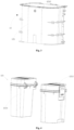
- Fig. 1 is a schematic diagram of an exploded structure of the cleaning device in an example of the disclosure
- Fig. 2 is a schematic cross-sectional view of the cleaning device in an example of the disclosure.
- the cleaning device 1 includes a main unit 11, a cleaning assembly 12 and at least one image collection module 13.
- the cleaning assembly 12 is arranged on the main unit 11, and the cleaning assembly 12 at least includes a water tank 121.
- the at least one image collection module 13 corresponds to the water tank 121 in position and is arranged facing the water tank 121.
- the at least one image collection module 13 collects an image of the water tank, so as to determine whether the water tank 121 is in place and/or a water volume status of the water tank 121.
- the image of the water tank is collected through the image collection module 13 corresponding to the water tank 121 in position, and a water level of the water tank 121 and whether the water tank 121 is in place are determined through the image of the water tank.
- the judgment logic is simple and intuitive, the number of components and structural arrangement of the cleaning device 1 are simplified, and an accuracy of water level monitoring and installation positioning of the water tank 121 are improved.
- the main unit 11 includes an image analysis module, the image analysis module is electrically connected to the image collection module 13, so as to acquire and analyze the image of the water tank and determine the water volume status of the water tank 121.
- the image of the water tank may be processed and analyzed through the image analysis module of the main unit 11.
- the image analysis module may further be configured to determine the water volume status of the water tank 121, which improves an analysis efficiency and accuracy of the image of the water tank.
- the cleaning device 1 further includes a limit fixing piece 14, the limit fixing piece 14 is in limit fit with the image collection module 13, and the limit fixing piece 14 is fixedly connected to the main unit 11.
- the image collection module 13 is fixedly assembled on the main unit 11 through the limit fixing piece 14, which improves a position accuracy and assembly reliability of the image collection module 13.
- the image collection module 13 is assembled on the main unitll, and the image collection module 13 is not disassembled with the water tank 121 relative to the main unit 11, which avoids the influence on the image collection module 13 in a process of disassembling the water tank 121 and adding water.
- the limit fixing piece 14 may be a cover plate, the cover plate is arranged above the image collection module 13 in a thickness direction Z of the cleaning device 1, and the cover plate is fixedly connected to the main unit 11.
- a limiting area of the image collection module 13 may be increased through the cover plate, the cover plate is above the image collection module 13, and the cover plate is fixedly connected to the main unit 11, which can avoid a position shift of the image collection module 13 in multiple directions caused by motion turbulence of the cleaning device 1 during use.
- the main unit 11 includes a bottom plate 111.
- the cleaning device 1 further includes a light transmission piece 15 assembled on the bottom plate 111 and located between the image collection module 13 and the water tank 121.
- the image collection module 13 includes a main body structure 131 and a lens 132 arranged on the main body structure 131, and the light transmission piece 15, the limit fixing piece 14, the bottom plate 111 and the main body structure 131 enclose a sealed space for accommodating the lens 132. Sealing with the lens 132 is realized through the light transmission piece 15, the limit fixing piece 14, the bottom plate 111 and the main body structure 131, and dustproof and waterproof functions of the lens 132 are realized on the condition that a shooting function of the lens 132 is ensured.
- the above light transmission piece 15 may be a light transmission optic.
- the bottom plate 111 includes a base plate 1111 and an extension wall 1112 arranged on the base plate 1111, and the extension wall 1112 is provided with an open hole 1113 corresponding to the lens 132 in position.
- the light transmission piece 15 is adhered to the extension wall 1112 through a sealing adhesive, and the light transmission piece 15 blocks the open hole 1113.
- the light transmission piece 15 is adhered, fixed and assembled through the extension wall 1112, which improves an assembly convenience of the light transmission piece 15, and can further ensure the assembly reliability of the light transmission piece 15.
- the image collection module 13 may also be fixedly assembled on the water tank 121.
- the image collection module 13 may be detachable fitted to the main unit 11 along with the water tank 121, and a relative positional relationship between the image collection module 13 and the water tank 121 is fixed, which prevents a presented water level and positioning accuracy of the water tank 121 from being affected by the change of the relative positional relationship between the water tank 121 and the image collection module 13 in the disassembling process.
- the water tank 121 includes a housing 1211 that encloses a water storage space and a water level observation part 1212 arranged on the housing 1211, so that the image collection module 13 can shoot a water level image through the water level observation part 1212.
- An assembly surface 1211a of the housing 1211 facing the main unit 11 is provided with a concave part 1211b recessed relative to the assembly surface 1211a, and the main unit 11 includes an assembly structure 112 fitted to the concave part 1211b.
- the image collection module 13 is assembled into an assembly space enclosed by the assembly structure 112, and the water level observation part 1212 is arranged on a first side wall 1211c forming the concave part 1211b.
- the assembly structure 112 of the main unit is in fit with the concave part 1211b, on the one hand, it facilitates the positioning and assembly of the main unit 11 and the water tank 121, and on the other hand, the water level observation part 1212 is arranged on the first side wall 1211c formed by the concave part 1211b, which facilitates the image collection module 13 located in the assembly space and corresponding to the water level observation part 1212 in position, so as to perform collection of the image of the water tank.
- the water level observation part 1212 may be a light transmission structure that forms at least a portion of the first side wall 1211c, and a water level situation in the water tank 121 can be directly observed through the light transmission structure.
- the cleaning assembly 12 includes a dust box 122.
- the at least one image collection module 13 corresponds to a second positioning part 122a of the dust box 122 in position, and the image collection module 13 acquires the image of the second positioning part 122a, so as to judge whether the dust box122 is in place according to the image of the second positioning part 122a.
- the second positioning part 122a may be a structure at a specific position of the dust box 122, when a relative positional relationship between the second positioning part 122a and the main unit 11 meets a preset condition in the image, it may be determined that the dust box 122 is in place.
- position images of the first positioning part 121a of the water tank 121 and the second positioning part 122a of the dust box 122 are respectively collected through the image collection module 13, which can judge whether the water tank 121 or the dust box 122 is assembled in place.
- whether other components assembled to the main unit 11 are assembled in place may further be observed through the image collection module 13, and its judgment solution is the same as a judgment solution of whether the above water tank 121 and the dust box 122 are in place, which will not repeated here.
- the cleaning device 1 may include a base station and/or a cleaning main body, and the main unit 11 includes a base station main unit or a cleaning main body main unit. That is, the cleaning device 1 may be the base station, and may also be the cleaning main body movable relative to the base station. As shown in Fig. 3 , when the cleaning device 1 is the cleaning main body, the water tank 121 may be a clean water tank, and whether a water volume status of the clean water tank is in place may be observed through the image collection module 13. When the cleaning device 1 is the base station, as shown in Fig.
- the water tank 121 may be a clean water tank 1213 or a dirty water tank 1214, water volume statuses of the clean water tank 1213 and the dirty water tank 1214 and whether the clean water tank 1213 and the dirty water tank 1214 are in place may be observed through the image collection module 13.
- the image collection module 13 may be a camera, a scanning device and the like, which is not limited by the disclosure.
- the above cleaning device 1 may be a floor sweeping robot, a glass cleaning device, a bed sweeping device and the like, which is not limited by the disclosure.
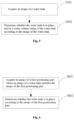
- Fig. 5 is a flow chart of a monitoring method of a cleaning device in an example of the disclosure. As shown in Fig. 5 , the monitoring method of the cleaning device 1 may be implemented by the following steps.
- step S501 an image of a water tank is acquired.
- the image of the water tank is collected through an image collection module 13 corresponding to the water tank 121 in position, and a water level of the water tank 121 and whether the water tank 121 is in place are determined through the image of the water tank.
- the judgment logic is simple and intuitive, the number of components and structural arrangement of the cleaning device 1 are simplified, and an accuracy of water level monitoring and installation positioning of the water tank 121 is improved.
- determining the water volume status of the water tank 121 according to the image of the water tank may include: a signal that the water tank 121 is in a full-tank water volume status is sent in a case that the image of the water tank matches an image feature of a preset full-tank water level; a signal that the water tank 121 is in a half-tank water volume status is sent in a case that the image of the water tank matches an image feature of a preset half-tank water level; and a signal that the water tank 121 is in an empty-tank water volume status is sent in a case that the image of the water tank matches an image feature of a preset empty-tank water level.
- a current water volume status of the water tank 121 is confirmed through image comparison, a user is reminded that the water tank is in a status of full water, water shortage and empty tank according to the water volume status, so that the user may add water to the clean water tank in a status of water shortage of the clean water tank and drain water in a status of full water of the dirty water tank, and the judgment logic is simple and easy to realize.
- the water tank 121 includes a first positioning part.
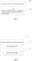
- Fig. 6 is a flow chart of a monitoring method of a cleaning device in another example of the disclosure. As shown in Fig. 6 , determining whether the water tank is in place according to the image of the water tank may be implemented by the following steps.
- step S601 an image of the first positioning part is acquired, where the image of the water tank includes the image of the first positioning part.
- step S602 whether the water tank is in place is determined according to the image of the first positioning part.
- a cleaning assembly 12 includes a dust box 122, and the dust box 122 includes a second positioning part.
- Fig. 7 is a flow chart of a monitoring method of a cleaning device in yet another example of the disclosure. As shown in Fig. 7 , the monitoring method of the cleaning device may be implemented by the following steps.
- step S701 an image of the second positioning part is acquired.
- step S702 whether the dust box 122 is in place is determined according to the image of the second positioning part.
- the images of the first positioning part 121a of the water tank 121 and the second positioning part 122a of the dust box 122 are respectively collected through the image collection module 13, which can judge whether the water tank 121 or the dust box 122 is assembled in place, and the judgment logic is simple and easy to realize.
- Fig. 8 is a structural block diagram of a monitoring apparatus of the cleaning device in an example of the disclosure.
- the monitoring apparatus 80 of the cleaning device 1 includes: a first acquiring unit 81 and a first processing unit 82.
- the first acquiring unit 81 is configured to acquire an image of a water tank.
- the first processing unit may include: a first processing subunit, a second processing subunit and a third processing subunit.
- the first processing subunit is configured to send a signal that the water tank 121 is in a full-tank water volume status in a case that the image of the water tank matches an image feature of a preset full-tank water level.
- the second processing subunit is configured to send a signal that the water tank 121 is in a half-tank water volume status in a case that the image of the water tank matches an image feature of a preset half-tank water level.
- the third processing subunit is configured to send a signal that the water tank 121 is in an empty-tank water volume status in a case that the image of the water tank matches an image feature of a preset empty-tank water level.
- the water tank 121 includes a first positioning part.
- Fig. 9 is a structural block diagram of a monitoring apparatus of a cleaning device in another example of the disclosure.
- the first processing unit 82 may include a first acquiring subunit 821 and a fourth processing subunit 822.
- the first acquiring subunit 821 is configured to acquire an image of the first positioning part.
- the image of the water tank includes the image of the first positioning part.
- the fourth processing subunit 822 is configured to determine whether the water tank is in place according to the image of the first positioning part.
- a cleaning assembly 12 may include a dust box 122, and the dust box 122 includes a second positioning part 122a.
- Fig. 10 is a structural block diagram of a monitoring apparatus of a cleaning device in yet another example of the disclosure. As shown in Fig. 10 , the monitoring apparatus 80 of the cleaning device 1 further includes: a second acquiring unit 83 and a second processing unit 84.
- the second acquiring unit 83 is configured to acquire an image of the second positioning part.
- the second processing unit 84 is configured to determine whether the dust box 122 is installed in place according to the image of the second positioning part.
- the related parts can take reference to the partial description of the method examples.
- the apparatus examples described above are merely illustrative.
- the units described as separate components may or may not be physically separated, and the components displayed as units may or may not be physical unit, that is, they may be located in one place, or may be distributed to multiple network units.
- Some or all of the modules may be selected according to actual needs to realize the purpose of the solution of the disclosure. Those of ordinary skill in the art can understand and implement it without creative work.
- the disclosure further provides an apparatus for cleaning device monitoring, including: a processor; and a memory configured to store processor-executable instructions.
- the processor is configured to: acquire an image of a water tank; and determine whether the water tank is in place and/or a water volume status of the water tank according to the image of the water tank.
- Fig. 11 is a block diagram of an apparatus for cleaning device monitoring illustrated by an example.
- an apparatus 1100 may be a mobile phone, a computer, a digital broadcasting terminal, a messaging device, a game console, a tablet device, a medical device, a fitness device, a personal digital assistant, etc.
- the apparatus 1100 may include one or more of the following components: a processing component 1102, a memory 1104, a power component 1106, a multimedia component 1108, an audio component 1110, an input/output (I/O) interface 1118, a sensor component 1114, and a communication component 1116.
- a processing component 1102 a memory 1104, a power component 1106, a multimedia component 1108, an audio component 1110, an input/output (I/O) interface 1118, a sensor component 1114, and a communication component 1116.
- the processing component 1102 typically controls an overall operation of the apparatus 1100, such as operations associated with display, telephone call, data communication, camera operations, and recording operations.
- the processing component 1102 may include one or more processors 1120 to execute instructions to complete all or part of the steps of the above method.
- the processing component 1102 may include one or more modules to facilitate interaction between the processing component 1102 and other components.
- the processing component 1102 may include a multimedia module to facilitate interaction between the multimedia component 1108 and the processing component 1102.
- the one or more processors 1120 may include one or more of the processing subunits.
- the memory 1104 is configured to store various types of data to support operations at the apparatus 1100. Instances of these data include instructions for any application or method operating on the apparatus 1100, contact data, phonebook data, messages, pictures, videos, etc.
- the memory 1104 may be implemented by any type of volatile or nonvolatile storage device or their combination, such as a static random access memory (SRAM), an electrically erasable programmable read only memory (EEPROM), an erasable programmable read only memory (EPROM), a programmable read only memory (PROM), a read only memory (ROM), a magnetic memory, a flash memory, a magnetic disk or an optic disk.
- SRAM static random access memory
- EEPROM electrically erasable programmable read only memory
- EPROM erasable programmable read only memory
- PROM programmable read only memory
- ROM read only memory
- the power component 1106 provides power for various components of the apparatus 1100.
- the power component 1106 may include a power management system, one or more power sources and other components associated with generating, managing and distributing power for the apparatus 1100.
- the multimedia component 1108 includes a screen providing an output interface between the apparatus 1100 and a user.
- the screen may include a liquid crystal display (LCD) and a touch panel (TP). If the screen includes the touch panel, the screen may be implemented as a touch screen to receive an input signal from the user.
- the touch panel includes one or more touch sensors to sense touch, sliding and gestures on the touch panel. The touch sensor cannot merely sense the boundary of the touch or sliding operation, but also detect the duration and pressure related to the touch or sliding operation.
- the multimedia component 1108 includes a front camera and/or a rear camera. When the apparatus 1100 is in an operation mode, such as a shooting mode or a video mode, the front camera and/or the rear camera can receive external multimedia data. Each front camera and rear camera can be a fixed optical lens system or have a focal length and optical zoom capability.
- the audio component 1110 is configured to output and/or input audio signals.
- the audio component 1110 includes a microphone (MIC) configured to receive an external audio signal when the apparatus 1100 is in the operation mode, such as a call mode, a recording mode, and a speech recognition mode.
- the received audio signal may be further stored in the memory 1104 or transmitted via the communication component 1116.
- the audio component 1110 further includes a speaker for outputting an audio signal.
- the I/O interface 1118 provides an interface between the processing component 1102 and a peripheral interface module which can be a keyboard, a click wheel, a button, etc. These buttons may include but are not limited to: a home button, volume buttons, a start button and a lock button.
- the sensor component 1114 includes one or more sensors for providing state evaluation of various aspects of the apparatus 1100.
- the sensor component 1114 can detect an on/off state of the apparatus 1100 and the relative positioning of the components, for example, the component is a display and a keypad of the apparatus 1100.
- the sensor component 1114 can also detect the change of the position of the apparatus 1100 or one component of the apparatus 1100, the presence or absence of user contact with the apparatus 1100, the azimuth or acceleration/deceleration of the apparatus 1100, and temperature change of the apparatus 1100.
- the sensor component 1114 may include a proximity sensor configured to detect the presence of nearby objects without any physical contact.
- the sensor component 1114 may further include an optical sensor, such as a CMOS or CCD image sensor, for use in imaging applications.
- the sensor component 1114 may further include an acceleration sensor, a gyroscope sensor, a magnetic sensor, a pressure sensor, or a temperature sensor.
- the communication component 1116 is configured to facilitate wired or wireless communication between the apparatus 1100 and other devices.
- the apparatus 1100 may access a wireless network based on a communication standard, such as WiFi, 2G or 14G, 4G LTE, 5G NR or their combination.
- the communication component 1116 receives a broadcast signal or broadcast-related information from an external broadcast management system via a broadcast channel.
- the communication component 1116 further includes a near field communication (NFC) module to facilitate short-range communication.
- the NFC module may be implemented based on a radio frequency identification (RFID) technology, an infrared data association (IrDA) technology, an ultra wideband (UWB) technology, a Bluetooth (BT) technology and other technologies.
- RFID radio frequency identification
- IrDA infrared data association
- UWB ultra wideband
- BT Bluetooth
- the apparatus 1100 may be implemented by one or more application-specific integrated circuits (ASICs), digital signal processors (DSPs), digital signal processing devices (DSPDs), programmable logic devices (PLDs), field programmable gate arrays (FPGAs), controllers, microcontrollers, microprocessors, or other electronic elements for performing the above method.
- ASICs application-specific integrated circuits
- DSPs digital signal processors
- DSPDs digital signal processing devices
- PLDs programmable logic devices
- FPGAs field programmable gate arrays
- controllers microcontrollers, microprocessors, or other electronic elements for performing the above method.
- the disclosure further provides a computer-readable storage medium, the computer-readable storage medium stores computer instructions, and the computer instructions, when executed by a processor, implement steps of the above monitoring method of the cleaning device.
- a non-temporary computer-readable storage medium including instructions is further provided, such as the memory 1104 including instructions, which can be executed by the processor 1120 of the apparatus 1100 to complete the above monitoring method of the cleaning device.
- the non-temporary computer-readable storage medium may be a ROM, a random access memory (RAM), a CD-ROM, a magnetic tape, a floppy disk, an optical data storage device, etc.
Landscapes
- Engineering & Computer Science (AREA)
- Mechanical Engineering (AREA)
- Cleaning By Liquid Or Steam (AREA)
- Investigating Or Analysing Materials By Optical Means (AREA)
Abstract
Description
- The disclosure relates to the technical field of cleaning devices, in particular to a cleaning device, and a monitoring method and apparatus of the cleaning device.
- A cleaning device, such as an intelligent sweeping and mopping robot, can automatically complete household cleaning, including sweeping, dust removal, rag mopping and the like, which greatly liberates people's hands and time. A water tank is a main component of the cleaning device, which can automatically replenish water to a rag in a sweeping and mopping process.
- The disclosure provides a cleaning device, and a monitoring method and apparatus of the cleaning device, so as to solve the related technical problems.
- A first aspect of the disclosure provides a cleaning device, including: a main unit; a cleaning assembly, arranged on the main unit, where the cleaning assembly at least includes a water tank; and at least one image collection module, corresponding to the water tank in position and arranged facing the water tank, where the at least one image collection module collects an image of the water tank, so as to determine whether the water tank is in place and/or a water volume status of the water tank.
- Optionally, the main unit includes an image analysis module, and the image analysis module is electrically connected to the image collection module, so as to acquire and analyze the image of the water tank.
- Optionally, the cleaning device further includes a limit fixing piece, the limit fixing piece is in limit fit with the image collection module, and the limit fixing piece is fixedly connected to the main unit.
- Optionally, the limit fixing piece includes a cover plate, the cover plate is arranged above the image collection module in a thickness direction of the cleaning device and the cover plate is fixedly connected to the main unit.
- Optionally, the main unit includes a bottom plate, and the cleaning device further includes a light transmission piece assembled on the bottom plate and located between the image collection module and the water tank; and the image collection module includes a main body structure and a lens arranged on the main body structure, and the light transmission piece, the limit fixing piece, the bottom plate and the main body structure enclose a sealed space for accommodating the lens.
- Optionally, the bottom plate includes a base plate and an extension wall arranged on the base plate, and the extension wall is provided with an open hole corresponding to the lens in position; and the light transmission piece is adhered to the extension wall by a sealing adhesive, and the light transmission piece blocks the open hole.
- Optionally, the image collection module is fixedly assembled on the water tank.
- Optionally, the water tank includes a housing that encloses a water storage space and a water level observation part arranged on the housing; and an assembly surface of the housing facing the main unit is provided with a concave part recessed relative to the assembly surface, and the main unit includes an assembly structure fitted to the concave part; and the image collection module is assembled into an assembly space enclosed by the assembly structure, and the water level observation part is arranged on a first side wall forming the concave part.
- Optionally, the first side wall is arranged obliquely relative to the assembly surface.
- Optionally, the water level observation part includes a light transmission structure forming at least a portion of the first side wall.
- Optionally, the water tank includes a first positioning part; and the image of the water tank includes an image of the first positioning part, so as to judge whether the water tank is in place according to the image of the first positioning part.
- Optionally, the cleaning assembly further includes a dust box; and the at least one image collection module corresponds to a second positioning part of the dust box in position, and the image collection module acquires an image of the second positioning part, so as to judge whether the dust box is in place according to the image of the second positioning part.
- Optionally, the cleaning device includes a base station and/or a cleaning main body; the water tank includes a clean water tank or a dirty water tank; and/or, the main unit includes a base station main unit or a cleaning main body main unit.
- According to a second aspect of the disclosure, a monitoring method of a cleaning device is provided and applied to a cleaning device, the method includes: acquiring an image of a water tank included in a cleaning assembly, arranged on a main unit, wherein the cleaning assembly at least comprises the water tank; and determining whether the water tank is in place and/or a water volume status of the water tank according to the image of the water tank using at least one image collection module, corresponding to the water tank in position and arranged facing the water tank, wherein the at least one image collection module collects an image of the water tank, so as to determine whether the water tank is in place and/or a water volume status of the water tank.
- Optionally, determining the water volume status of the water tank according to the image of the water tank, includes: sending a signal that the water tank is in a full-tank water volume status in a case that the image of the water tank matches an image feature of a preset full-tank water level; sending a signal that the water tank is in a half-tank water volume status in a case that the image of the water tank matches an image feature of a preset half-tank water level; and sending a signal that the water tank is in an empty-tank water volume status in a case that the image of the water tank matches an image feature of a preset empty-tank water level.
- Optionally, the water tank includes a first positioning part, and determining whether the water tank is in place according to the image of the water tank includes: acquiring an image of the first positioning part, where the image of the water tank includes the image of the first positioning part; and determining whether the water tank is in place according to the image of the first positioning part.
- Optionally, a cleaning assembly includes a dust box, and the dust box includes a second positioning part; and the method further includes: acquiring an image of the second positioning part; and determining whether the dust box is in place according to the image of the second positioning part.
- According to a third aspect of the disclosure, a monitoring apparatus of a cleaning device is provided and applied to a cleaning device, the cleaning device includes: a main unit; a cleaning assembly, arranged on the main unit, where the cleaning assembly at least includes a water tank; and at least one image collection module, corresponding to the water tank in position and arranged facing the water tank, where the at least one image collection module collects an image of the water tank, so as to determine whether the water tank is in place and/or a water volume status of the water tank; the apparatus includes: a first acquiring unit, acquiring an image of a water tank; and a first processing unit, determining whether the water tank is in place and/or a water volume status of the water tank according to the image of the water tank.
- Optionally, the first processing unit includes: a first processing subunit, sending a signal that the water tank is in a full-tank water volume status in a case that the image of the water tank matches an image feature of a preset full-tank water level; a second processing subunit, sending a signal that the water tank is in a half-tank water volume status in a case that the image of the water tank matches an image feature of a preset half-tank water level; and a third processing subunit, sending a signal that the water tank is in an empty-tank water volume status in a case that the image of the water tank matches an image feature of a preset empty-tank water level.
- Optionally, the water tank includes a first positioning part, and the first processing unit includes: a first acquiring subunit, acquiring an image of the first positioning part, where the image of the water tank includes the image of the first positioning part; and a fourth processing subunit, determining whether the water tank is in place according to the image of the first positioning part.
- Optionally, a cleaning assembly includes a dust box, and the dust box includes a second positioning part; the apparatus further includes: a second acquiring unit, acquiring an image of the second positioning part; and a second processing unit, determining whether the dust box is in place according to the image of the second positioning part.
- According to a fourth aspect of the disclosure, a computer program is provided, the computer program including instructions to cause the above cleaning device to execute the steps of any monitoring method of the cleaning device described in the second aspect.
- According to a fifth aspect of the disclosure, a computer-readable storage medium is provided, the computer-readable medium having stored thereon the computer program described in the fourth aspect.
- The technical solution provided by the disclosure at least may realize the following beneficial effects:
- in the disclosure, the image of the water tank is collected through the image collection module corresponding to the water tank in position, and a water level of the water tank and whether the water tank is in place are determined through the image of the water tank. The judgment logic is simple and intuitive, the number of components and structural arrangement of the cleaning device are simplified, and an accuracy of water level monitoring and installation positioning of the water tank is improved.
- It should be understood that the above general descriptions and the following detailed descriptions are merely explanatory and illustrative, and cannot limit the disclosure.
-
-
Fig. 1 is a schematic diagram of an exploded structure of a cleaning device in an example of the disclosure. -
Fig. 2 is a schematic cross-sectional view of a cleaning device in an example of the disclosure. -
Fig. 3 is a schematic diagram of an exploded structure of a water tank and an image collection module in an example of the disclosure. -
Fig. 4 is a schematic diagram of an exploded structure of a clean water tank and a dirty water tank in an example of the disclosure. -
Fig. 5 is a flow chart of a monitoring method of a cleaning device in an example of the disclosure. -
Fig. 6 is a flow chart of a monitoring method of a cleaning device in another example of the disclosure. -
Fig. 7 is a flow chart of a monitoring method of a cleaning device in yet another example of the disclosure. -
Fig. 8 is a structural block diagram of a monitoring apparatus of a cleaning device in an example of the disclosure. -
Fig. 9 is a structural block diagram of a monitoring apparatus of a cleaning device in another example of the disclosure. -
Fig. 10 is a structural block diagram of a monitoring apparatus of a cleaning device in yet another example of the disclosure. -
Fig. 11 is a block diagram of an apparatus for cleaning device monitoring illustrated by an example. - Examples will be described in detail here, and instances are shown in the accompanying drawings. When the following description refers to the accompanying drawings, unless otherwise indicated, the same numbers in different accompanying drawings indicate the same or similar elements. The implementations described in the following examples do not represent all implementations consistent with the disclosure. Rather, they are merely instances of apparatuses and methods consistent with some aspects of the disclosure.
- The terms used in the disclosure are merely for the purpose of describing specific examples, and not intended to limit the disclosure. Unless otherwise defined, technical or scientific terms used in the disclosure shall have the ordinary meanings understood by those ordinarily skilled in the art to which the disclosure pertains. The words "first", "second" and the similar words used in the disclosure do not indicate any order, quantity or importance, but are merely used to distinguish different components. As such, nor "one" or "a" or similar words indicate quantity limitations, but indicate at least one. If merely "one" is referred to, it will be explained separately. "A plurality of' or "several" means two or more than two. Unless otherwise indicated, "front", "rear", "lower" and/or "upper", "top", "bottom" and other similar words are merely for convenience of description and are not limited to one location or a spatial orientation. "Comprise" or "include" and other similar words indicate that an element or item appearing before "comprise" or "include" covers listed elements or items appearing after "comprise" or "include" and their equivalents, and do not exclude other elements or items. "Connect" or "couple" and the similar words are not limited to physical or mechanical connection, but also may include electrical connection, whether direct or indirect.
- "X" in
Figure 1 indicates the transverse direction of the cleaning device; "Y" inFigure 1 and Figure 2 indicates the longitudinal direction of the cleaning device; "Z" inFigure 1 and Figure 2 indicates the thickness direction of the cleaning device. Where "X", "Y", and "Z" are perpendicular to each other. - A cleaning device, such as an intelligent sweeping and mopping robot, can automatically complete household cleaning, including sweeping, dust removal, rag mopping and the like, which greatly liberates people's hands and time. A water tank is a main component of the cleaning device, which can automatically replenish water to a rag in a sweeping and mopping process. In the related art, the water volume detection of the water tank is usually realized based on a principle of a photoelectric sensor or a principle of Hall detection combined with a principle of magnetic floating, which has the problems of many related components and complex structures and principles.
- The disclosure provides a cleaning device.
Fig. 1 is a schematic diagram of an exploded structure of the cleaning device in an example of the disclosure, andFig. 2 is a schematic cross-sectional view of the cleaning device in an example of the disclosure. As shown inFig. 1 and Fig. 2 , the cleaning device 1 includes amain unit 11, a cleaningassembly 12 and at least oneimage collection module 13. The cleaningassembly 12 is arranged on themain unit 11, and the cleaningassembly 12 at least includes awater tank 121. The at least oneimage collection module 13 corresponds to thewater tank 121 in position and is arranged facing thewater tank 121. The at least oneimage collection module 13 collects an image of the water tank, so as to determine whether thewater tank 121 is in place and/or a water volume status of thewater tank 121. - The image of the water tank is collected through the
image collection module 13 corresponding to thewater tank 121 in position, and a water level of thewater tank 121 and whether thewater tank 121 is in place are determined through the image of the water tank. The judgment logic is simple and intuitive, the number of components and structural arrangement of the cleaning device 1 are simplified, and an accuracy of water level monitoring and installation positioning of thewater tank 121 are improved. - In some examples, the
main unit 11 includes an image analysis module, the image analysis module is electrically connected to theimage collection module 13, so as to acquire and analyze the image of the water tank and determine the water volume status of thewater tank 121. The image of the water tank may be processed and analyzed through the image analysis module of themain unit 11. The image analysis module may further be configured to determine the water volume status of thewater tank 121, which improves an analysis efficiency and accuracy of the image of the water tank. - In some examples, the cleaning device 1 further includes a
limit fixing piece 14, thelimit fixing piece 14 is in limit fit with theimage collection module 13, and thelimit fixing piece 14 is fixedly connected to themain unit 11. Theimage collection module 13 is fixedly assembled on themain unit 11 through thelimit fixing piece 14, which improves a position accuracy and assembly reliability of theimage collection module 13. In addition, theimage collection module 13 is assembled on the main unitll, and theimage collection module 13 is not disassembled with thewater tank 121 relative to themain unit 11, which avoids the influence on theimage collection module 13 in a process of disassembling thewater tank 121 and adding water. - In the above examples, the
limit fixing piece 14 may be a cover plate, the cover plate is arranged above theimage collection module 13 in a thickness direction Z of the cleaning device 1, and the cover plate is fixedly connected to themain unit 11. A limiting area of theimage collection module 13 may be increased through the cover plate, the cover plate is above theimage collection module 13, and the cover plate is fixedly connected to themain unit 11, which can avoid a position shift of theimage collection module 13 in multiple directions caused by motion turbulence of the cleaning device 1 during use. - In some examples, the
main unit 11 includes abottom plate 111. The cleaning device 1 further includes alight transmission piece 15 assembled on thebottom plate 111 and located between theimage collection module 13 and thewater tank 121. Theimage collection module 13 includes amain body structure 131 and alens 132 arranged on themain body structure 131, and thelight transmission piece 15, thelimit fixing piece 14, thebottom plate 111 and themain body structure 131 enclose a sealed space for accommodating thelens 132. Sealing with thelens 132 is realized through thelight transmission piece 15, thelimit fixing piece 14, thebottom plate 111 and themain body structure 131, and dustproof and waterproof functions of thelens 132 are realized on the condition that a shooting function of thelens 132 is ensured. It needs to be noted that the abovelight transmission piece 15 may be a light transmission optic. - In the above examples, the
bottom plate 111 includes abase plate 1111 and anextension wall 1112 arranged on thebase plate 1111, and theextension wall 1112 is provided with anopen hole 1113 corresponding to thelens 132 in position. Thelight transmission piece 15 is adhered to theextension wall 1112 through a sealing adhesive, and thelight transmission piece 15 blocks theopen hole 1113. Thelight transmission piece 15 is adhered, fixed and assembled through theextension wall 1112, which improves an assembly convenience of thelight transmission piece 15, and can further ensure the assembly reliability of thelight transmission piece 15. - In some examples, the
image collection module 13 may also be fixedly assembled on thewater tank 121. Theimage collection module 13 may be detachable fitted to themain unit 11 along with thewater tank 121, and a relative positional relationship between theimage collection module 13 and thewater tank 121 is fixed, which prevents a presented water level and positioning accuracy of thewater tank 121 from being affected by the change of the relative positional relationship between thewater tank 121 and theimage collection module 13 in the disassembling process. - In some examples, the
water tank 121 includes ahousing 1211 that encloses a water storage space and a waterlevel observation part 1212 arranged on thehousing 1211, so that theimage collection module 13 can shoot a water level image through the waterlevel observation part 1212. Anassembly surface 1211a of thehousing 1211 facing themain unit 11 is provided with aconcave part 1211b recessed relative to theassembly surface 1211a, and themain unit 11 includes anassembly structure 112 fitted to theconcave part 1211b. Theimage collection module 13 is assembled into an assembly space enclosed by theassembly structure 112, and the waterlevel observation part 1212 is arranged on afirst side wall 1211c forming theconcave part 1211b. Theassembly structure 112 of the main unit is in fit with theconcave part 1211b, on the one hand, it facilitates the positioning and assembly of themain unit 11 and thewater tank 121, and on the other hand, the waterlevel observation part 1212 is arranged on thefirst side wall 1211c formed by theconcave part 1211b, which facilitates theimage collection module 13 located in the assembly space and corresponding to the waterlevel observation part 1212 in position, so as to perform collection of the image of the water tank. - In the above examples, the
first side wall 1211c may be arranged obliquely relative to theassembly surface 1211a, so as to increase a space between thefirst side wall 1211c and themain unit 11, on the one hand, structural interference between thewater tank 121 and themain unit 11 is avoided, and on the other hand, the image collection of theimage collection module 13 is facilitated. - In the above examples, the water
level observation part 1212 may be a light transmission structure that forms at least a portion of thefirst side wall 1211c, and a water level situation in thewater tank 121 can be directly observed through the light transmission structure. - In some examples, the
water tank 121 includes afirst positioning part 121a, and the image of the water tank includes an image of thefirst positioning part 121a, so as to judge whether thewater tank 121 is in place according to the image of thefirst positioning part 121a. Thefirst positioning part 121a may be a structure at a specific position of thewater tank 121, when a relative positional relationship between thefirst positioning part 121a and themain unit 11 meets a preset condition in the image, it may be determined that thewater tank 121 is in place. - In some examples, the cleaning
assembly 12 includes adust box 122. The at least oneimage collection module 13 corresponds to asecond positioning part 122a of thedust box 122 in position, and theimage collection module 13 acquires the image of thesecond positioning part 122a, so as to judge whether the dust box122 is in place according to the image of thesecond positioning part 122a. Similarly, thesecond positioning part 122a may be a structure at a specific position of thedust box 122, when a relative positional relationship between thesecond positioning part 122a and themain unit 11 meets a preset condition in the image, it may be determined that thedust box 122 is in place. - In the above examples, position images of the
first positioning part 121a of thewater tank 121 and thesecond positioning part 122a of thedust box 122 are respectively collected through theimage collection module 13, which can judge whether thewater tank 121 or thedust box 122 is assembled in place. - In other examples, whether other components assembled to the
main unit 11 are assembled in place may further be observed through theimage collection module 13, and its judgment solution is the same as a judgment solution of whether theabove water tank 121 and thedust box 122 are in place, which will not repeated here. - In the above examples, the cleaning device 1 may include a base station and/or a cleaning main body, and the
main unit 11 includes a base station main unit or a cleaning main body main unit. That is, the cleaning device 1 may be the base station, and may also be the cleaning main body movable relative to the base station. As shown inFig. 3 , when the cleaning device 1 is the cleaning main body, thewater tank 121 may be a clean water tank, and whether a water volume status of the clean water tank is in place may be observed through theimage collection module 13. When the cleaning device 1 is the base station, as shown inFig. 4 , thewater tank 121 may be aclean water tank 1213 or adirty water tank 1214, water volume statuses of theclean water tank 1213 and thedirty water tank 1214 and whether theclean water tank 1213 and thedirty water tank 1214 are in place may be observed through theimage collection module 13. - It needs to be noted that the
image collection module 13 may be a camera, a scanning device and the like, which is not limited by the disclosure. The above cleaning device 1 may be a floor sweeping robot, a glass cleaning device, a bed sweeping device and the like, which is not limited by the disclosure. - The disclosure further provides a monitoring method of a cleaning device, applied to the above cleaning device 1.
Fig. 5 is a flow chart of a monitoring method of a cleaning device in an example of the disclosure. As shown inFig. 5 , the monitoring method of the cleaning device 1 may be implemented by the following steps. - In step S501, an image of a water tank is acquired.
- In step S502, it is determined whether the
water tank 121 is in place and/or a water volume status of thewater tank 121 is according to the image of the water tank. - The image of the water tank is collected through an
image collection module 13 corresponding to thewater tank 121 in position, and a water level of thewater tank 121 and whether thewater tank 121 is in place are determined through the image of the water tank. The judgment logic is simple and intuitive, the number of components and structural arrangement of the cleaning device 1 are simplified, and an accuracy of water level monitoring and installation positioning of thewater tank 121 is improved. - In the above examples, determining the water volume status of the
water tank 121 according to the image of the water tank may include: a signal that thewater tank 121 is in a full-tank water volume status is sent in a case that the image of the water tank matches an image feature of a preset full-tank water level; a signal that thewater tank 121 is in a half-tank water volume status is sent in a case that the image of the water tank matches an image feature of a preset half-tank water level; and a signal that thewater tank 121 is in an empty-tank water volume status is sent in a case that the image of the water tank matches an image feature of a preset empty-tank water level. A current water volume status of thewater tank 121 is confirmed through image comparison, a user is reminded that the water tank is in a status of full water, water shortage and empty tank according to the water volume status, so that the user may add water to the clean water tank in a status of water shortage of the clean water tank and drain water in a status of full water of the dirty water tank, and the judgment logic is simple and easy to realize. - The
water tank 121 includes a first positioning part.Fig. 6 is a flow chart of a monitoring method of a cleaning device in another example of the disclosure. As shown inFig. 6 , determining whether the water tank is in place according to the image of the water tank may be implemented by the following steps. - In step S601, an image of the first positioning part is acquired, where the image of the water tank includes the image of the first positioning part.
- In step S602, whether the water tank is in place is determined according to the image of the first positioning part.
- In some examples, a cleaning
assembly 12 includes adust box 122, and thedust box 122 includes a second positioning part.Fig. 7 is a flow chart of a monitoring method of a cleaning device in yet another example of the disclosure. As shown inFig. 7 , the monitoring method of the cleaning device may be implemented by the following steps. - In step S701, an image of the second positioning part is acquired.
- In step S702, whether the
dust box 122 is in place is determined according to the image of the second positioning part. - The images of the
first positioning part 121a of thewater tank 121 and thesecond positioning part 122a of thedust box 122 are respectively collected through theimage collection module 13, which can judge whether thewater tank 121 or thedust box 122 is assembled in place, and the judgment logic is simple and easy to realize. - The disclosure further provides a monitoring apparatus of a cleaning device 1, applied to the above cleaning device 1.
Fig. 8 is a structural block diagram of a monitoring apparatus of the cleaning device in an example of the disclosure. As shown inFig. 8 , themonitoring apparatus 80 of the cleaning device 1 includes: a first acquiringunit 81 and afirst processing unit 82. - The first acquiring
unit 81 is configured to acquire an image of a water tank. - The
first processing unit 82 is configured to determine whether thewater tank 121 is in place and/or a water volume status of thewater tank 121 according to the image of the water tank. - The first processing unit may include: a first processing subunit, a second processing subunit and a third processing subunit.
- The first processing subunit is configured to send a signal that the
water tank 121 is in a full-tank water volume status in a case that the image of the water tank matches an image feature of a preset full-tank water level. - The second processing subunit is configured to send a signal that the
water tank 121 is in a half-tank water volume status in a case that the image of the water tank matches an image feature of a preset half-tank water level. - The third processing subunit is configured to send a signal that the
water tank 121 is in an empty-tank water volume status in a case that the image of the water tank matches an image feature of a preset empty-tank water level. - The
water tank 121 includes a first positioning part.Fig. 9 is a structural block diagram of a monitoring apparatus of a cleaning device in another example of the disclosure. As shown inFig. 9 , thefirst processing unit 82 may include a first acquiringsubunit 821 and afourth processing subunit 822. - The first acquiring
subunit 821 is configured to acquire an image of the first positioning part. The image of the water tank includes the image of the first positioning part. - The
fourth processing subunit 822 is configured to determine whether the water tank is in place according to the image of the first positioning part. - A cleaning
assembly 12 may include adust box 122, and thedust box 122 includes asecond positioning part 122a.Fig. 10 is a structural block diagram of a monitoring apparatus of a cleaning device in yet another example of the disclosure. As shown inFig. 10 , themonitoring apparatus 80 of the cleaning device 1 further includes: a second acquiringunit 83 and asecond processing unit 84. - The second acquiring
unit 83 is configured to acquire an image of the second positioning part. - The
second processing unit 84 is configured to determine whether thedust box 122 is installed in place according to the image of the second positioning part. - As for the apparatus in the above examples, the specific manner in which each module performs operations has been described in detail in the examples of the method, and detailed description will not be given here.
- As for the apparatus examples, as it basically corresponds to the method examples, the related parts can take reference to the partial description of the method examples. The apparatus examples described above are merely illustrative. The units described as separate components may or may not be physically separated, and the components displayed as units may or may not be physical unit, that is, they may be located in one place, or may be distributed to multiple network units. Some or all of the modules may be selected according to actual needs to realize the purpose of the solution of the disclosure. Those of ordinary skill in the art can understand and implement it without creative work.
- Accordingly, the disclosure further provides an apparatus for cleaning device monitoring, including: a processor; and a memory configured to store processor-executable instructions. The processor is configured to: acquire an image of a water tank; and determine whether the water tank is in place and/or a water volume status of the water tank according to the image of the water tank.
-
Fig. 11 is a block diagram of an apparatus for cleaning device monitoring illustrated by an example. For example, anapparatus 1100 may be a mobile phone, a computer, a digital broadcasting terminal, a messaging device, a game console, a tablet device, a medical device, a fitness device, a personal digital assistant, etc. - Referring to
Fig. 11 , theapparatus 1100 may include one or more of the following components: aprocessing component 1102, amemory 1104, apower component 1106, amultimedia component 1108, anaudio component 1110, an input/output (I/O)interface 1118, asensor component 1114, and acommunication component 1116. - The
processing component 1102 typically controls an overall operation of theapparatus 1100, such as operations associated with display, telephone call, data communication, camera operations, and recording operations. Theprocessing component 1102 may include one ormore processors 1120 to execute instructions to complete all or part of the steps of the above method. In addition, theprocessing component 1102 may include one or more modules to facilitate interaction between theprocessing component 1102 and other components. For example, theprocessing component 1102 may include a multimedia module to facilitate interaction between themultimedia component 1108 and theprocessing component 1102. The one ormore processors 1120 may include one or more of the processing subunits. - The
memory 1104 is configured to store various types of data to support operations at theapparatus 1100. Instances of these data include instructions for any application or method operating on theapparatus 1100, contact data, phonebook data, messages, pictures, videos, etc. Thememory 1104 may be implemented by any type of volatile or nonvolatile storage device or their combination, such as a static random access memory (SRAM), an electrically erasable programmable read only memory (EEPROM), an erasable programmable read only memory (EPROM), a programmable read only memory (PROM), a read only memory (ROM), a magnetic memory, a flash memory, a magnetic disk or an optic disk. - The
power component 1106 provides power for various components of theapparatus 1100. Thepower component 1106 may include a power management system, one or more power sources and other components associated with generating, managing and distributing power for theapparatus 1100. - The
multimedia component 1108 includes a screen providing an output interface between theapparatus 1100 and a user. In some examples, the screen may include a liquid crystal display (LCD) and a touch panel (TP). If the screen includes the touch panel, the screen may be implemented as a touch screen to receive an input signal from the user. The touch panel includes one or more touch sensors to sense touch, sliding and gestures on the touch panel. The touch sensor cannot merely sense the boundary of the touch or sliding operation, but also detect the duration and pressure related to the touch or sliding operation. In some examples, themultimedia component 1108 includes a front camera and/or a rear camera. When theapparatus 1100 is in an operation mode, such as a shooting mode or a video mode, the front camera and/or the rear camera can receive external multimedia data. Each front camera and rear camera can be a fixed optical lens system or have a focal length and optical zoom capability. - The
audio component 1110 is configured to output and/or input audio signals. For example, theaudio component 1110 includes a microphone (MIC) configured to receive an external audio signal when theapparatus 1100 is in the operation mode, such as a call mode, a recording mode, and a speech recognition mode. The received audio signal may be further stored in thememory 1104 or transmitted via thecommunication component 1116. In some examples, theaudio component 1110 further includes a speaker for outputting an audio signal. - The I/
O interface 1118 provides an interface between theprocessing component 1102 and a peripheral interface module which can be a keyboard, a click wheel, a button, etc. These buttons may include but are not limited to: a home button, volume buttons, a start button and a lock button. - The
sensor component 1114 includes one or more sensors for providing state evaluation of various aspects of theapparatus 1100. For example, thesensor component 1114 can detect an on/off state of theapparatus 1100 and the relative positioning of the components, for example, the component is a display and a keypad of theapparatus 1100. Thesensor component 1114 can also detect the change of the position of theapparatus 1100 or one component of theapparatus 1100, the presence or absence of user contact with theapparatus 1100, the azimuth or acceleration/deceleration of theapparatus 1100, and temperature change of theapparatus 1100. Thesensor component 1114 may include a proximity sensor configured to detect the presence of nearby objects without any physical contact. Thesensor component 1114 may further include an optical sensor, such as a CMOS or CCD image sensor, for use in imaging applications. In some examples, thesensor component 1114 may further include an acceleration sensor, a gyroscope sensor, a magnetic sensor, a pressure sensor, or a temperature sensor. - The
communication component 1116 is configured to facilitate wired or wireless communication between theapparatus 1100 and other devices. Theapparatus 1100 may access a wireless network based on a communication standard, such as WiFi, 2G or 14G, 4G LTE, 5G NR or their combination. In an example, thecommunication component 1116 receives a broadcast signal or broadcast-related information from an external broadcast management system via a broadcast channel. In an example, thecommunication component 1116 further includes a near field communication (NFC) module to facilitate short-range communication. For example, the NFC module may be implemented based on a radio frequency identification (RFID) technology, an infrared data association (IrDA) technology, an ultra wideband (UWB) technology, a Bluetooth (BT) technology and other technologies. - In an example, the
apparatus 1100 may be implemented by one or more application-specific integrated circuits (ASICs), digital signal processors (DSPs), digital signal processing devices (DSPDs), programmable logic devices (PLDs), field programmable gate arrays (FPGAs), controllers, microcontrollers, microprocessors, or other electronic elements for performing the above method. - The disclosure further provides a computer-readable storage medium, the computer-readable storage medium stores computer instructions, and the computer instructions, when executed by a processor, implement steps of the above monitoring method of the cleaning device. In an example, a non-temporary computer-readable storage medium including instructions is further provided, such as the
memory 1104 including instructions, which can be executed by theprocessor 1120 of theapparatus 1100 to complete the above monitoring method of the cleaning device. For example, the non-temporary computer-readable storage medium may be a ROM, a random access memory (RAM), a CD-ROM, a magnetic tape, a floppy disk, an optical data storage device, etc.
Claims (15)
- A cleaning device (1), comprising:a main unit (11);a cleaning assembly (12), arranged on the main unit (11), wherein the cleaning assembly (12) at least comprises a water tank (121); andat least one image collection module (13), corresponding to the water tank (121) in position and arranged facing the water tank (121), wherein the at least one image collection module (13) collects an image of the water tank, so as to determine whether the water tank (121) is in place and/or a water volume status of the water tank (121).
- The cleaning device according to claim 1, wherein the main unit (11) comprises an image analysis module, and the image analysis module is electrically connected to the image collection module (13), so as to acquire and analyze the image of the water tank.
- The cleaning device according to claim 1 or 2, wherein the cleaning device (1) further comprises a limit fixing piece (14), the limit fixing piece (14) is in limit fit with the image collection module (13), and the limit fixing piece (14) is fixedly connected to the main unit (11).
- The cleaning device according to claim 3, wherein the limit fixing piece (14) comprises a cover plate, the cover plate is arranged above the image collection module (13) in a thickness direction of the cleaning device (1), and the cover plate is fixedly connected to the main unit (11).
- The cleaning device according to claim 3 or 4, wherein the main unit (11) comprises a bottom plate (111), and the cleaning device (1) further comprises a light transmission piece (15) assembled on the bottom plate (111) and located between the image collection module (13) and the water tank (121); andthe image collection module (13) comprises a main body structure (131) and a lens (132) arranged on the main body structure (131), and the light transmission piece (132), the limit fixing piece (14), the bottom plate (111) and the main body structure (131) enclose a sealed space for accommodating the lens (132),optionally, the bottom plate (111) comprises a base plate (1111) and an extension wall (1112) arranged on the base plate (1111), and the extension wall (1112) is provided with an open hole (1113) corresponding to the lens (132) in position; and the light transmission piece (15) is adhered to the extension wall (1112) by a sealing adhesive, and the light transmission piece (15) blocks the open hole (1113).
- The cleaning device according to any one of claims 1 to 5, wherein the image collection module (13) is fixedly assembled on the water tank (121).
- The cleaning device according to any one of claims 1 to 6, wherein the water tank (121) comprises a housing (1211) that encloses a water storage space and a water level observation part (1212) arranged on the housing (1211); and an assembly surface (1211a) of the housing (1211) facing the main unit (11) is provided with a concave part (1211b) recessed relative to the assembly surface (1211a), and the main unit (11) comprises an assembly structure (112) fitted to the concave part (1211b); and
the image collection module (13) is assembled into an assembly space enclosed by the assembly structure (112), and the water level observation part (1212) is arranged on a first side wall (1211c) forming the concave part (1211b). - The cleaning device according to claim 7, wherein the first side wall (1211c) is arranged obliquely relative to the assembly surface (1211a),
optionally, the water level observation part (1212) comprises a light transmission structure forming at least a portion of the first side wall (1211c). - The cleaning device according to any one of claims 1 to 8, wherein the water tank (121) comprises a first positioning part (121a); and the image of the water tank comprises an image of the first positioning part (121a), so as to judge whether the water tank (121) is in place according to the image of the first positioning part (121a);or, wherein the cleaning assembly (12) further comprises a dust box (122); andthe at least one image collection module (13) corresponds to a second positioning part (122a) of the dust box (122) in position, and the image collection module (13) acquires an image of the second positioning part (122a), so as to judge whether the dust box (122) is in place according to the image of the second positioning part (122a).
- The cleaning device according to any one of claims 1 to 9, wherein the cleaning device (1) comprises a base station and/or a cleaning main body; whereinthe water tank (121) comprises a clean water tank (1213) or a dirty water tank (1214);and/or, the main unit (11) comprises a base station main unit or a cleaning main body main unit.
- A monitoring method of a cleaning device, applied to the cleaning device (1), the method comprises:Acquiring (S501 ) an image of a water tank included in a cleaning assembly (12), arranged on a main unit (11), wherein the cleaning assembly (12) at least comprises the water tank (121); andDetermining (S502) whether the water tank (121) is in place and/or a water volume status of the water tank (121) according to the image of the water tank using at least one image collection module (13), corresponding to the water tank (121) in position and arranged facing the water tank (121), wherein the at least one image collection module (13) collects an image of the water tank, so as to determine whether the water tank (121) is in place and/or a water volume status of the water tank (121).
- The monitoring method of the cleaning device according to claim 11, wherein determining the water volume status of the water tank according to the image of the water tank, comprises:sending a signal that the water tank is in a full-tank water volume status in a case that the image of the water tank matches an image feature of a preset full-tank water level;sending a signal that the water tank is in a half-tank water volume status in a case that the image of the water tank matches an image feature of a preset half-tank water level; andsending a signal that the water tank is in an empty-tank water volume status in a case that the image of the water tank matches an image feature of a preset empty-tank water level.
- The monitoring method of the cleaning device according to claim 11 or 12, wherein the water tank (121) comprises a first positioning part (121a), and determining whether the water tank (121) is in place according to the image of the water tank comprises:Acquiring (S601) an image of the first positioning part, wherein the image of the water tank comprises the image of the first positioning part; anddetermining (S602) whether the water tank is in place according to the image of the first positioning part, preferably the cleaning assembly (12) comprises a dust box (122), and the dust box (122) comprises a second positioning part (122a); and the method further comprises:acquiring (S701) an image of the second positioning part; anddetermining (S702) whether the dust box is in place according to the image of the second positioning part.
- A computer program comprising instructions to cause the cleaning device of claim 1 to execute the steps of the methods of any of claims 11 to 13.
- A computer-readable medium having stored thereon the computer program of claim 14.
Applications Claiming Priority (1)
| Application Number | Priority Date | Filing Date | Title |
|---|---|---|---|
| CN202210763105.7A CN115089054B (en) | 2022-06-29 | 2022-06-29 | Cleaning equipment, cleaning equipment monitoring methods and devices |
Publications (2)
| Publication Number | Publication Date |
|---|---|
| EP4298974A1 true EP4298974A1 (en) | 2024-01-03 |
| EP4298974B1 EP4298974B1 (en) | 2025-04-02 |
Family
ID=83295674
Family Applications (1)
| Application Number | Title | Priority Date | Filing Date |
|---|---|---|---|
| EP22198579.9A Active EP4298974B1 (en) | 2022-06-29 | 2022-09-29 | Cleaning device, and monitoring method and apparatus of cleaning device |
Country Status (3)
| Country | Link |
|---|---|
| US (1) | US20240000280A1 (en) |
| EP (1) | EP4298974B1 (en) |
| CN (1) | CN115089054B (en) |
Citations (3)
| Publication number | Priority date | Publication date | Assignee | Title |
|---|---|---|---|---|
| CN111166249A (en) * | 2020-02-28 | 2020-05-19 | 科沃斯机器人股份有限公司 | Control method of self-moving robot, self-moving robot and water tank assembly |
| CN112641388A (en) * | 2020-12-30 | 2021-04-13 | 苏州三六零机器人科技有限公司 | Mopping assembly, sweeping robot and waterless adjusting method |
| US20220071464A1 (en) * | 2020-09-04 | 2022-03-10 | Shenzhen Fly Rodent Dynamics Intelligent Technology Co., Ltd. | Cleaning robot |
Family Cites Families (8)
| Publication number | Priority date | Publication date | Assignee | Title |
|---|---|---|---|---|
| US12329337B2 (en) * | 2018-12-21 | 2025-06-17 | Positec Power Tools (Suzhou) Co., Ltd. | Robot cleaning system, base station, and control method |
| CN110381289B (en) * | 2019-04-15 | 2020-02-14 | 桑尼环保(江苏)有限公司 | Command distribution execution system |
| CN110547727A (en) * | 2019-08-14 | 2019-12-10 | 深圳市银星智能科技股份有限公司 | Fluid applying method for cleaning robot and cleaning robot |
| KR102858592B1 (en) * | 2019-08-27 | 2025-09-15 | 엘지전자 주식회사 | AI Robot Cleaner And Robot system having the same |
| CN110946523A (en) * | 2019-12-24 | 2020-04-03 | 合肥高美清洁设备有限责任公司 | Unmanned ground cleaning machine supply station |
| CN112107221A (en) * | 2020-08-10 | 2020-12-22 | 华帝股份有限公司 | Cooking equipment capable of improving shooting effect and control method thereof |
| CN113693500A (en) * | 2021-06-09 | 2021-11-26 | 北京石头世纪科技股份有限公司 | Cleaning system, cleaning equipment and control method for continuous dragging of water shortage breakpoint |
| CN113951768B (en) * | 2021-11-08 | 2023-05-30 | 北京小米移动软件有限公司 | Cleaning equipment base station and cleaning equipment system |
-
2022
- 2022-06-29 CN CN202210763105.7A patent/CN115089054B/en active Active
- 2022-09-28 US US17/955,061 patent/US20240000280A1/en active Pending
- 2022-09-29 EP EP22198579.9A patent/EP4298974B1/en active Active
Patent Citations (3)
| Publication number | Priority date | Publication date | Assignee | Title |
|---|---|---|---|---|
| CN111166249A (en) * | 2020-02-28 | 2020-05-19 | 科沃斯机器人股份有限公司 | Control method of self-moving robot, self-moving robot and water tank assembly |
| US20220071464A1 (en) * | 2020-09-04 | 2022-03-10 | Shenzhen Fly Rodent Dynamics Intelligent Technology Co., Ltd. | Cleaning robot |
| CN112641388A (en) * | 2020-12-30 | 2021-04-13 | 苏州三六零机器人科技有限公司 | Mopping assembly, sweeping robot and waterless adjusting method |
Also Published As
| Publication number | Publication date |
|---|---|
| US20240000280A1 (en) | 2024-01-04 |
| CN115089054A (en) | 2022-09-23 |
| CN115089054B (en) | 2024-03-05 |
| EP4298974B1 (en) | 2025-04-02 |
Similar Documents
| Publication | Publication Date | Title |
|---|---|---|
| US9392102B2 (en) | Apparatus and method for providing panoramic view during video telephony and video messaging | |
| EP3301551B1 (en) | Electronic device for identifying touch | |
| EP3023928A1 (en) | Method and device for setting task | |
| JP6138453B2 (en) | Equipment with videophone function, program, and control method of equipment with videophone function | |
| CN101090442A (en) | Method and apparatus for taking images using mobile communication terminal with plurality of camera lenses | |
| KR20150064955A (en) | Mobile terminal | |
| CN104834559A (en) | Notification message display method and device | |
| CN106506733B (en) | Mobile terminal | |
| KR101717532B1 (en) | Mobile terminal and method for controlling the same | |
| US20240205315A1 (en) | Handheld electronic device | |
| CN110109608B (en) | Text display method, text display device, text display terminal and storage medium | |
| CN112799582A (en) | Terminal, terminal holding gesture recognition method and device, and storage medium | |
| CN104065883B (en) | Image pickup method and device | |
| CN109089137B (en) | Stuck detection method and device | |
| KR101688176B1 (en) | Method, apparatus, terminal, program, and recording medium for call transfer | |
| EP3771232A1 (en) | Information reporting and configuration method and device, user equipment and base station | |
| CN105517144A (en) | Equipment positioning method and device | |
| KR20160098871A (en) | Waterproof case and mobile terminal using the same | |
| CN105491292A (en) | Method and device for shooting fill-in light | |
| EP4298974B1 (en) | Cleaning device, and monitoring method and apparatus of cleaning device | |
| WO2017067162A1 (en) | Mobile phone | |
| CN105589622A (en) | Chatting method and device based on pop-up comment | |
| US20170155755A1 (en) | Electronic apparatus and method for controlling electronic apparatus | |
| CN105611341A (en) | Image transmission method, device and system | |
| EP2563008B1 (en) | Method and apparatus for performing video communication in a mobile terminal |
Legal Events
| Date | Code | Title | Description |
|---|---|---|---|
| PUAI | Public reference made under article 153(3) epc to a published international application that has entered the european phase |
Free format text: ORIGINAL CODE: 0009012 |
|
| STAA | Information on the status of an ep patent application or granted ep patent |
Free format text: STATUS: REQUEST FOR EXAMINATION WAS MADE |
|
| 17P | Request for examination filed |
Effective date: 20220929 |
|
| AK | Designated contracting states |
Kind code of ref document: A1 Designated state(s): AL AT BE BG CH CY CZ DE DK EE ES FI FR GB GR HR HU IE IS IT LI LT LU LV MC MK MT NL NO PL PT RO RS SE SI SK SM TR |
|
| RBV | Designated contracting states (corrected) |
Designated state(s): AL AT BE BG CH CY CZ DE DK EE ES FI FR GB GR HR HU IE IS IT LI LT LU LV MC MK MT NL NO PL PT RO RS SE SI SK SM TR |
|
| GRAP | Despatch of communication of intention to grant a patent |
Free format text: ORIGINAL CODE: EPIDOSNIGR1 |
|
| STAA | Information on the status of an ep patent application or granted ep patent |
Free format text: STATUS: GRANT OF PATENT IS INTENDED |
|
| RIC1 | Information provided on ipc code assigned before grant |
Ipc: A47L 9/30 20060101ALI20241007BHEP Ipc: A47L 9/28 20060101ALI20241007BHEP Ipc: A47L 9/14 20060101ALI20241007BHEP Ipc: A47L 11/40 20060101AFI20241007BHEP |
|
| INTG | Intention to grant announced |
Effective date: 20241024 |
|
| GRAS | Grant fee paid |
Free format text: ORIGINAL CODE: EPIDOSNIGR3 |
|
| GRAA | (expected) grant |
Free format text: ORIGINAL CODE: 0009210 |
|
| STAA | Information on the status of an ep patent application or granted ep patent |
Free format text: STATUS: THE PATENT HAS BEEN GRANTED |
|
| P01 | Opt-out of the competence of the unified patent court (upc) registered |
Free format text: CASE NUMBER: APP_5497/2025 Effective date: 20250203 |
|
| AK | Designated contracting states |
Kind code of ref document: B1 Designated state(s): AL AT BE BG CH CY CZ DE DK EE ES FI FR GB GR HR HU IE IS IT LI LT LU LV MC MK MT NL NO PL PT RO RS SE SI SK SM TR |
|
| REG | Reference to a national code |
Ref country code: GB Ref legal event code: FG4D |
|
| REG | Reference to a national code |
Ref country code: CH Ref legal event code: EP |
|
| REG | Reference to a national code |
Ref country code: IE Ref legal event code: FG4D |
|
| REG | Reference to a national code |
Ref country code: DE Ref legal event code: R096 Ref document number: 602022012508 Country of ref document: DE |
|
| REG | Reference to a national code |
Ref country code: NL Ref legal event code: MP Effective date: 20250402 |
|
| PG25 | Lapsed in a contracting state [announced via postgrant information from national office to epo] |
Ref country code: NL Free format text: LAPSE BECAUSE OF FAILURE TO SUBMIT A TRANSLATION OF THE DESCRIPTION OR TO PAY THE FEE WITHIN THE PRESCRIBED TIME-LIMIT Effective date: 20250402 |
|
| REG | Reference to a national code |
Ref country code: AT Ref legal event code: MK05 Ref document number: 1780442 Country of ref document: AT Kind code of ref document: T Effective date: 20250402 |
|
| PG25 | Lapsed in a contracting state [announced via postgrant information from national office to epo] |
Ref country code: FI Free format text: LAPSE BECAUSE OF FAILURE TO SUBMIT A TRANSLATION OF THE DESCRIPTION OR TO PAY THE FEE WITHIN THE PRESCRIBED TIME-LIMIT Effective date: 20250402 Ref country code: ES Free format text: LAPSE BECAUSE OF FAILURE TO SUBMIT A TRANSLATION OF THE DESCRIPTION OR TO PAY THE FEE WITHIN THE PRESCRIBED TIME-LIMIT Effective date: 20250402 Ref country code: PT Free format text: LAPSE BECAUSE OF FAILURE TO SUBMIT A TRANSLATION OF THE DESCRIPTION OR TO PAY THE FEE WITHIN THE PRESCRIBED TIME-LIMIT Effective date: 20250804 |
|
| PGFP | Annual fee paid to national office [announced via postgrant information from national office to epo] |
Ref country code: DE Payment date: 20250919 Year of fee payment: 4 |
|
| REG | Reference to a national code |
Ref country code: LT Ref legal event code: MG9D |
|
| PG25 | Lapsed in a contracting state [announced via postgrant information from national office to epo] |
Ref country code: NO Free format text: LAPSE BECAUSE OF FAILURE TO SUBMIT A TRANSLATION OF THE DESCRIPTION OR TO PAY THE FEE WITHIN THE PRESCRIBED TIME-LIMIT Effective date: 20250702 Ref country code: GR Free format text: LAPSE BECAUSE OF FAILURE TO SUBMIT A TRANSLATION OF THE DESCRIPTION OR TO PAY THE FEE WITHIN THE PRESCRIBED TIME-LIMIT Effective date: 20250703 |
|
| PG25 | Lapsed in a contracting state [announced via postgrant information from national office to epo] |
Ref country code: PL Free format text: LAPSE BECAUSE OF FAILURE TO SUBMIT A TRANSLATION OF THE DESCRIPTION OR TO PAY THE FEE WITHIN THE PRESCRIBED TIME-LIMIT Effective date: 20250402 |
|
| PG25 | Lapsed in a contracting state [announced via postgrant information from national office to epo] |
Ref country code: BG Free format text: LAPSE BECAUSE OF FAILURE TO SUBMIT A TRANSLATION OF THE DESCRIPTION OR TO PAY THE FEE WITHIN THE PRESCRIBED TIME-LIMIT Effective date: 20250402 |
|
| PG25 | Lapsed in a contracting state [announced via postgrant information from national office to epo] |
Ref country code: HR Free format text: LAPSE BECAUSE OF FAILURE TO SUBMIT A TRANSLATION OF THE DESCRIPTION OR TO PAY THE FEE WITHIN THE PRESCRIBED TIME-LIMIT Effective date: 20250402 |
|
| PG25 | Lapsed in a contracting state [announced via postgrant information from national office to epo] |
Ref country code: AT Free format text: LAPSE BECAUSE OF FAILURE TO SUBMIT A TRANSLATION OF THE DESCRIPTION OR TO PAY THE FEE WITHIN THE PRESCRIBED TIME-LIMIT Effective date: 20250402 |
|
| PG25 | Lapsed in a contracting state [announced via postgrant information from national office to epo] |
Ref country code: RS Free format text: LAPSE BECAUSE OF FAILURE TO SUBMIT A TRANSLATION OF THE DESCRIPTION OR TO PAY THE FEE WITHIN THE PRESCRIBED TIME-LIMIT Effective date: 20250702 |
|
| PG25 | Lapsed in a contracting state [announced via postgrant information from national office to epo] |
Ref country code: IS Free format text: LAPSE BECAUSE OF FAILURE TO SUBMIT A TRANSLATION OF THE DESCRIPTION OR TO PAY THE FEE WITHIN THE PRESCRIBED TIME-LIMIT Effective date: 20250802 |
|
| PG25 | Lapsed in a contracting state [announced via postgrant information from national office to epo] |
Ref country code: LV Free format text: LAPSE BECAUSE OF FAILURE TO SUBMIT A TRANSLATION OF THE DESCRIPTION OR TO PAY THE FEE WITHIN THE PRESCRIBED TIME-LIMIT Effective date: 20250402 |
|
| REG | Reference to a national code |
Ref country code: DE Ref legal event code: R097 Ref document number: 602022012508 Country of ref document: DE |
|
| PG25 | Lapsed in a contracting state [announced via postgrant information from national office to epo] |
Ref country code: SM Free format text: LAPSE BECAUSE OF FAILURE TO SUBMIT A TRANSLATION OF THE DESCRIPTION OR TO PAY THE FEE WITHIN THE PRESCRIBED TIME-LIMIT Effective date: 20250402 Ref country code: DK Free format text: LAPSE BECAUSE OF FAILURE TO SUBMIT A TRANSLATION OF THE DESCRIPTION OR TO PAY THE FEE WITHIN THE PRESCRIBED TIME-LIMIT Effective date: 20250402 |
|
| PG25 | Lapsed in a contracting state [announced via postgrant information from national office to epo] |
Ref country code: CZ Free format text: LAPSE BECAUSE OF FAILURE TO SUBMIT A TRANSLATION OF THE DESCRIPTION OR TO PAY THE FEE WITHIN THE PRESCRIBED TIME-LIMIT Effective date: 20250402 |
|
| PG25 | Lapsed in a contracting state [announced via postgrant information from national office to epo] |
Ref country code: EE Free format text: LAPSE BECAUSE OF FAILURE TO SUBMIT A TRANSLATION OF THE DESCRIPTION OR TO PAY THE FEE WITHIN THE PRESCRIBED TIME-LIMIT Effective date: 20250402 |
|
| PG25 | Lapsed in a contracting state [announced via postgrant information from national office to epo] |
Ref country code: SK Free format text: LAPSE BECAUSE OF FAILURE TO SUBMIT A TRANSLATION OF THE DESCRIPTION OR TO PAY THE FEE WITHIN THE PRESCRIBED TIME-LIMIT Effective date: 20250402 |
|
| PG25 | Lapsed in a contracting state [announced via postgrant information from national office to epo] |
Ref country code: IT Free format text: LAPSE BECAUSE OF FAILURE TO SUBMIT A TRANSLATION OF THE DESCRIPTION OR TO PAY THE FEE WITHIN THE PRESCRIBED TIME-LIMIT Effective date: 20250402 |
|
| PLBE | No opposition filed within time limit |
Free format text: ORIGINAL CODE: 0009261 |
|
| STAA | Information on the status of an ep patent application or granted ep patent |
Free format text: STATUS: NO OPPOSITION FILED WITHIN TIME LIMIT |
|
| REG | Reference to a national code |
Ref country code: CH Ref legal event code: L10 Free format text: ST27 STATUS EVENT CODE: U-0-0-L10-L00 (AS PROVIDED BY THE NATIONAL OFFICE) Effective date: 20260211 |
|
| PG25 | Lapsed in a contracting state [announced via postgrant information from national office to epo] |
Ref country code: RO Free format text: LAPSE BECAUSE OF FAILURE TO SUBMIT A TRANSLATION OF THE DESCRIPTION OR TO PAY THE FEE WITHIN THE PRESCRIBED TIME-LIMIT Effective date: 20250402 |
|
| 26N | No opposition filed |
Effective date: 20260105 |
|
| REG | Reference to a national code |
Ref country code: CH Ref legal event code: H13 Free format text: ST27 STATUS EVENT CODE: U-0-0-H10-H13 (AS PROVIDED BY THE NATIONAL OFFICE) Effective date: 20260425 |