EP4298392B1 - Heat exchange reactor seal apparatus - Google Patents
Heat exchange reactor seal apparatus Download PDFInfo
- Publication number
- EP4298392B1 EP4298392B1 EP22704413.8A EP22704413A EP4298392B1 EP 4298392 B1 EP4298392 B1 EP 4298392B1 EP 22704413 A EP22704413 A EP 22704413A EP 4298392 B1 EP4298392 B1 EP 4298392B1
- Authority
- EP
- European Patent Office
- Prior art keywords
- heat exchange
- tube
- process fluid
- tubes
- inner tube
- Prior art date
- Legal status (The legal status is an assumption and is not a legal conclusion. Google has not performed a legal analysis and makes no representation as to the accuracy of the status listed.)
- Active
Links
Images

Classifications
-
- F—MECHANICAL ENGINEERING; LIGHTING; HEATING; WEAPONS; BLASTING
- F28—HEAT EXCHANGE IN GENERAL
- F28D—HEAT-EXCHANGE APPARATUS, NOT PROVIDED FOR IN ANOTHER SUBCLASS, IN WHICH THE HEAT-EXCHANGE MEDIA DO NOT COME INTO DIRECT CONTACT
- F28D7/00—Heat-exchange apparatus having stationary tubular conduit assemblies for both heat-exchange media, the media being in contact with different sides of a conduit wall
- F28D7/16—Heat-exchange apparatus having stationary tubular conduit assemblies for both heat-exchange media, the media being in contact with different sides of a conduit wall the conduits being arranged in parallel spaced relation
-
- B—PERFORMING OPERATIONS; TRANSPORTING
- B01—PHYSICAL OR CHEMICAL PROCESSES OR APPARATUS IN GENERAL
- B01J—CHEMICAL OR PHYSICAL PROCESSES, e.g. CATALYSIS OR COLLOID CHEMISTRY; THEIR RELEVANT APPARATUS
- B01J19/00—Chemical, physical or physico-chemical processes in general; Their relevant apparatus
- B01J19/0053—Details of the reactor
- B01J19/0073—Sealings
-
- B—PERFORMING OPERATIONS; TRANSPORTING
- B01—PHYSICAL OR CHEMICAL PROCESSES OR APPARATUS IN GENERAL
- B01J—CHEMICAL OR PHYSICAL PROCESSES, e.g. CATALYSIS OR COLLOID CHEMISTRY; THEIR RELEVANT APPARATUS
- B01J8/00—Chemical or physical processes in general, conducted in the presence of fluids and solid particles; Apparatus for such processes
- B01J8/02—Chemical or physical processes in general, conducted in the presence of fluids and solid particles; Apparatus for such processes with stationary particles, e.g. in fixed beds
- B01J8/06—Chemical or physical processes in general, conducted in the presence of fluids and solid particles; Apparatus for such processes with stationary particles, e.g. in fixed beds in tube reactors; the solid particles being arranged in tubes
-
- B—PERFORMING OPERATIONS; TRANSPORTING
- B01—PHYSICAL OR CHEMICAL PROCESSES OR APPARATUS IN GENERAL
- B01J—CHEMICAL OR PHYSICAL PROCESSES, e.g. CATALYSIS OR COLLOID CHEMISTRY; THEIR RELEVANT APPARATUS
- B01J8/00—Chemical or physical processes in general, conducted in the presence of fluids and solid particles; Apparatus for such processes
- B01J8/02—Chemical or physical processes in general, conducted in the presence of fluids and solid particles; Apparatus for such processes with stationary particles, e.g. in fixed beds
- B01J8/06—Chemical or physical processes in general, conducted in the presence of fluids and solid particles; Apparatus for such processes with stationary particles, e.g. in fixed beds in tube reactors; the solid particles being arranged in tubes
- B01J8/067—Heating or cooling the reactor
-
- C—CHEMISTRY; METALLURGY
- C01—INORGANIC CHEMISTRY
- C01B—NON-METALLIC ELEMENTS; COMPOUNDS THEREOF; METALLOIDS OR COMPOUNDS THEREOF NOT COVERED BY SUBCLASS C01C
- C01B3/00—Hydrogen; Gaseous mixtures containing hydrogen; Separation of hydrogen from mixtures containing it; Purification of hydrogen; Reversible storage of hydrogen
- C01B3/02—Production of hydrogen; Production of gaseous mixtures containing hydrogen
- C01B3/32—Production of hydrogen; Production of gaseous mixtures containing hydrogen by reaction of gaseous or liquid organic compounds with gasifying agents, e.g. water, carbon dioxide or air
- C01B3/34—Production of hydrogen; Production of gaseous mixtures containing hydrogen by reaction of gaseous or liquid organic compounds with gasifying agents, e.g. water, carbon dioxide or air by reaction of hydrocarbons with gasifying agents
- C01B3/38—Production of hydrogen; Production of gaseous mixtures containing hydrogen by reaction of gaseous or liquid organic compounds with gasifying agents, e.g. water, carbon dioxide or air by reaction of hydrocarbons with gasifying agents using catalysts
- C01B3/384—Production of hydrogen; Production of gaseous mixtures containing hydrogen by reaction of gaseous or liquid organic compounds with gasifying agents, e.g. water, carbon dioxide or air by reaction of hydrocarbons with gasifying agents using catalysts with external heating of the catalyst
-
- F—MECHANICAL ENGINEERING; LIGHTING; HEATING; WEAPONS; BLASTING
- F28—HEAT EXCHANGE IN GENERAL
- F28D—HEAT-EXCHANGE APPARATUS, NOT PROVIDED FOR IN ANOTHER SUBCLASS, IN WHICH THE HEAT-EXCHANGE MEDIA DO NOT COME INTO DIRECT CONTACT
- F28D1/00—Heat-exchange apparatus having stationary conduit assemblies for one heat-exchange medium only, the media being in contact with different sides of the conduit wall, in which the other heat-exchange medium is a large body of fluid, e.g. domestic or motor car radiators
- F28D1/02—Heat-exchange apparatus having stationary conduit assemblies for one heat-exchange medium only, the media being in contact with different sides of the conduit wall, in which the other heat-exchange medium is a large body of fluid, e.g. domestic or motor car radiators with heat-exchange conduits immersed in the body of fluid
- F28D1/04—Heat-exchange apparatus having stationary conduit assemblies for one heat-exchange medium only, the media being in contact with different sides of the conduit wall, in which the other heat-exchange medium is a large body of fluid, e.g. domestic or motor car radiators with heat-exchange conduits immersed in the body of fluid with tubular conduits
-
- F—MECHANICAL ENGINEERING; LIGHTING; HEATING; WEAPONS; BLASTING
- F28—HEAT EXCHANGE IN GENERAL
- F28F—DETAILS OF HEAT-EXCHANGE AND HEAT-TRANSFER APPARATUS, OF GENERAL APPLICATION
- F28F9/00—Casings; Header boxes; Auxiliary supports for elements; Auxiliary members within casings
- F28F9/02—Header boxes; End plates
- F28F9/04—Arrangements for sealing elements into header boxes or end plates
- F28F9/06—Arrangements for sealing elements into header boxes or end plates by dismountable joints
-
- F—MECHANICAL ENGINEERING; LIGHTING; HEATING; WEAPONS; BLASTING
- F28—HEAT EXCHANGE IN GENERAL
- F28F—DETAILS OF HEAT-EXCHANGE AND HEAT-TRANSFER APPARATUS, OF GENERAL APPLICATION
- F28F9/00—Casings; Header boxes; Auxiliary supports for elements; Auxiliary members within casings
- F28F9/02—Header boxes; End plates
- F28F9/04—Arrangements for sealing elements into header boxes or end plates
- F28F9/16—Arrangements for sealing elements into header boxes or end plates by permanent joints, e.g. by rolling
- F28F9/165—Arrangements for sealing elements into header boxes or end plates by permanent joints, e.g. by rolling by using additional preformed parts, e.g. sleeves, gaskets
-
- C—CHEMISTRY; METALLURGY
- C01—INORGANIC CHEMISTRY
- C01B—NON-METALLIC ELEMENTS; COMPOUNDS THEREOF; METALLOIDS OR COMPOUNDS THEREOF NOT COVERED BY SUBCLASS C01C
- C01B2203/00—Integrated processes for the production of hydrogen or synthesis gas
- C01B2203/10—Catalysts for performing the hydrogen forming reactions
- C01B2203/1041—Composition of the catalyst
- C01B2203/1047—Group VIII metal catalysts
- C01B2203/1052—Nickel or cobalt catalysts
- C01B2203/1058—Nickel catalysts
-
- F—MECHANICAL ENGINEERING; LIGHTING; HEATING; WEAPONS; BLASTING
- F28—HEAT EXCHANGE IN GENERAL
- F28D—HEAT-EXCHANGE APPARATUS, NOT PROVIDED FOR IN ANOTHER SUBCLASS, IN WHICH THE HEAT-EXCHANGE MEDIA DO NOT COME INTO DIRECT CONTACT
- F28D21/00—Heat-exchange apparatus not covered by any of the groups F28D1/00 - F28D20/00
- F28D2021/0019—Other heat exchangers for particular applications; Heat exchange systems not otherwise provided for
- F28D2021/0022—Other heat exchangers for particular applications; Heat exchange systems not otherwise provided for for chemical reactors
-
- F—MECHANICAL ENGINEERING; LIGHTING; HEATING; WEAPONS; BLASTING
- F28—HEAT EXCHANGE IN GENERAL
- F28F—DETAILS OF HEAT-EXCHANGE AND HEAT-TRANSFER APPARATUS, OF GENERAL APPLICATION
- F28F9/00—Casings; Header boxes; Auxiliary supports for elements; Auxiliary members within casings
- F28F9/22—Arrangements for directing heat-exchange media into successive compartments, e.g. arrangements of guide plates
- F28F2009/222—Particular guide plates, baffles or deflectors, e.g. having particular orientation relative to an elongated casing or conduit
- F28F2009/226—Transversal partitions
-
- F—MECHANICAL ENGINEERING; LIGHTING; HEATING; WEAPONS; BLASTING
- F28—HEAT EXCHANGE IN GENERAL
- F28F—DETAILS OF HEAT-EXCHANGE AND HEAT-TRANSFER APPARATUS, OF GENERAL APPLICATION
- F28F2230/00—Sealing means
Definitions
- This invention relates to seal apparatus and its use in a heat exchange reactors and processes using such apparatus, in particular in catalytic steam reforming processes.
- the Applicant has found that disrupting the flow of heat exchange medium within the seal device by creating turbulence in the annular space between the exterior of the inner tube and the interior of the seal tube can reduce the amount of mixing of the heat exchange medium with the process fluid.
- the invention provides a tube seal according to claim 1.
- the one or more grooves in the expansion region may be on an outer face of the inner tube or on the inner face of the seal tube.
- the one or more grooves in the overlapping region corresponding to the expansion region of the inner tube are disposed on the outer face of the inner tube because this simplifies fabrication.
- the tube seal device comprises an inner tube.
- the inner tube may be connected to one end of the heat exchange tube or may be formed as an end portion of the heat exchange tube.
- the inner tube may have the same diameter as the heat exchange tube or, preferably, a narrower diameter than the heat exchange tube.
- the inner tube may be polygonal or cylindrical but is preferably shaped so that an even clearance space is formed between the outer face of the inner tube and the inner face of the seal tube in the overlapping region.
- the inner tube has an internal constriction forming a low-pressure region within the tube and an expanded portion adjacent the constriction forming an expansion zone within the tube.
- One or more passages through the wall of the inner tube connect the low-pressure region with the exterior of the inner tube.
- the device is orientated such that the expansion zone is located downstream of the low-pressure zone.
- the expansion region will be below the constriction in the inner tube.
- the relative sizes of the constriction, low-pressure region and expansion region will depend in part on the tube size.
- the portion of tubes forming the inner tube may have an internal dimension of about 25 mm, tapering internally to a constriction of about 12 mm internal diameter opening into a low-pressure region of about 18 mm internal diameter and about 108 mm length.
- the inner tube may be flared from the 18 mm diameter to about 31 mm external diameter over a length of about 78 mm. Twelve evenly spaced passages of 3 mm diameter may be provided between the low-pressure region and the exterior of the inner tube.
- the tube seal device comprises one or more grooves on the inner face of the seal tube.
- the one or more grooves on the inner face of the seal tube are formed on the inner face of the seal tube in the overlapping region corresponding to the low-pressure region of the inner tube.
- the one or more grooves on the inner face of the seal tube may be formed as crenellations, i.e. having a square or rectangular form, or the grooves may be U-shaped, V-shaped, or any combination of these. Square or rectangular-shaped grooves may provide improved turbulence in the overlapping region.
- the one or more grooves may additionally be one or more grooves in the overlapping region corresponding to the expansion region of the inner tube.
- the one or more grooves may also be formed as crenellations, i.e. having a square or rectangular form, or the grooves may be U-shaped, V-shaped, or any combination of these.
- the size of the grooves in this region may also be from 2 to 20 mm in width, e.g. 6 to 14 mm in width, and 1 to 7 mm in depth.
- the one or more grooves are desirably arranged to disrupt the flow of gas through the tube seal device.
- the one or more grooves may be arranged perpendicular to the flow of process fluid through the inner tube, or the grooves may be formed in a spiral manner, such as a screw thread.
- two or more grooves are present, in either the low-pressure or expansion regions, they are preferably parallel to each other.
- the invention further provides a process according to claim 12.
- part of the processed process fluid fed to the heat exchange zone passes into the tube seal device and through the one or more passages into the low pressure region.
- the heat exchange medium is the process fluid that has passed through the tubes, but which has been subjected to further processing before being used as the heat exchange medium.
- This further processing preferably includes a step in which the process fluid is heated such that the heat exchange medium imparts heat to the one or more heat exchange tubes.
- the tube seal device is of particular utility in a heat exchange steam reformer, or gas-heated reformer, i.e. a heat exchange reactor containing a one or more externally heated tubes containing a steam reforming catalyst through which a reformer feed is passed to generate a synthesis gas, and wherein the heat exchange is medium used to heat the tubes.
- the heat exchange medium is typically at lower pressure than the reformer feed.
- the process and apparatus are of particular utility for steam reforming hydrocarbons wherein a mixture of a hydrocarbon feedstock and steam is passed through the heat exchange tubes which contain a steam reforming catalyst, for example a nickel-containing steam reforming catalyst, so as to form a primary reformed gas which is then subjected to partial combustion with an oxygen-containing gas and the resultant partially combusted gas is used as the heat exchange medium in the heat exchange zone.
- a steam reforming catalyst for example a nickel-containing steam reforming catalyst
- the partially combusted gas is passed through a bed of a secondary reforming catalyst, so as to effect further reforming, before being used as the heat exchange medium.
- a low-pressure region is formed within the inner tube: by suitably sizing the constriction, the pressure in the low-pressure region when in normal operation can be made lower than the pressure in the heat exchange zone so that there is a flow of heat exchange medium, e.g. the product of secondary reforming the process fluid taken from the process fluid off-take zone, from the heat exchange zone through the clearance space between the seal tube and the inner tube and through said passages in the wall of the inner tube into the low-pressure region. Downstream of the low-pressure region the process fluid expands in the expansion region giving a process fluid pressure greater than that in the low-pressure region. Consequently, there can also be a backflow, or recycle, of process fluid from the outlet end of the inner tube, through the clearance space, to the passages and into the low-pressure region.
- heat exchange medium e.g. the product of secondary reforming the process fluid taken from the process fluid off-take zone
- the tube seal device is preferably provided at the boundary means between the heat exchange zone and the process fluid off-take zone.
- the seal tubes are preferably fastened to that boundary means while the one or more heat exchange tubes comprising the inner tubes are fastened to the boundary means, e.g. tube sheet, between the process fluid inlet zone and the heat exchange zone.
- the inner tubes are formed at the end of the heat exchange tubes adjacent the boundary means between the heat exchange zone and the process fluid off-take zone and therefore engage with the seal tubes at this boundary means to form the tube seal device. This is especially preferred where the process fluid undergoes a substantial pressure drop as it passes through the heat exchange tubes, for example where the latter contain a catalyst.
- the seal tubes may project into the heat exchange zone from the boundary means or may extend back from the boundary means into the process fluid off-take zone, on the other side of the boundary means.
- hydrocarbon feedstock is typically a methane-containing gas.
- methane reacts with steam to produce hydrogen and carbon oxides. Any hydrocarbons containing two or more carbon atoms that are present are converted to methane, carbon monoxide and hydrogen.
- Steam reforming reactions take place in the tubes over the steam reforming catalysts at temperatures above 350°C and typically the process fluid exiting the tubes is at a temperature in the range 650 to 950°C.
- the heat exchange medium flowing around the outside of the tubes may have a temperature in the range 500 to 2000°C.
- the apparatus and process may be used as part of a process for the manufacture of hydrogen, methanol, dimethyl ether, olefins, ammonia, urea or hydrocarbon liquids, e.g. diesel fuels, obtained by the Fischer-Tropsch synthesis.
- a reformed gas mixture obtained using the apparatus or in the process of the present invention may be subjected to further process steps including a step of hydrogen separation, methanol synthesis, dimethyl ether synthesis, olefin synthesis, ammonia synthesis, or hydrocarbon liquid synthesis.
- Known processes may be used to accomplish these steps.
- FIG. 1 there is shown a heat exchange steam reformer, having an outer insulated pressure shell 10 enclosing three zones 11, 12, 13, defined by the shell wall and tube sheets 14 and 15.
- Zone 11 a process fluid feed zone, is defined by the shell wall 10 and tube sheet 14.
- It is provided with a process fluid supply conduit 16 and has a plurality of vertical tubes, 17 fastened to, and extending downwards from, tube sheet 14.
- the number of tubes employed will depend on the scale of operation: although only five tubes are shown, there may be typically be 50 or more such tubes.
- the tubes 17 are filled with a steam reforming catalyst 18, for example multi-holed cylindrical pellets of a refractory oxide-supported nickel catalyst and/or a structured steam reforming catalyst.
- Zone 12 a heat exchange zone, is defined by the shell wall 10 and tube sheets 14 and 15.
- the heat exchange tubes 17 extend through the heat exchange zone 12 and engage with tube seal devices 20.
- the tube seal devices 20 each comprise a seal tube 21 fixed to the tube sheet 15 that engage, in the heat exchange zone 12, with catalyst-free inner tube sections 22 extending from the bottom of the catalyst-filled tubes 17.
- the heat exchange zone 12 is fed with a heating medium, e.g. a synthesis gas produced by autothermal or secondary reforming, via a conduit 23 positioned in the shell 10 near the bottom of the tubes 17.
- the heating medium passes upward in the heat exchange zone where it exchanges heat with the tubes 17 and is then removed from the heat exchange zone 12 via a conduit 24 positioned in the shell 10 near the top of the tubes 17.
- Transverse baffles 25 act to divert the heating medium horizontally across the reformer and enhance its heat exchange with the tubes 17.
- Zone 13 the process fluid off-take zone, is defined by the wall of shell 10 and the tube sheet 15.
- the tube seal devices 20 are open-ended and extend through the tube sheet 15 into the off-take zone 13.
- the reformed gases pass from the tubes 17 through the tube seal devices 20 and into the off-take zone 13 from which they are removed by a process fluid off-take conduit 26.
- a process fluid comprising hydrocarbon and steam is fed at elevated temperature and pressure through the conduit 16 to the process fluid feed zone 11 and thence downward through the catalyst-filled tubes 17. Heat is exchanged with heating medium in the heat exchange zone 12 and steam reforming reactions take place.
- the gas mixture undergoing reforming passes through the tubes 17 and thence though tube seal devices 20 to the off-take zone 13 from which it is removed by the off-take conduit 26.
- a reformed gas recovered from the off-take conduit 26 is subjected to further processing in which it is heated, in particular by autothermal or secondary reforming, and the further processed gas passed to the heat exchange reformer via conduit 23 as the heat exchange medium.
- the pressure of the heat exchange medium fed via conduit 23 is lower than the gas passing though the tubes 17.
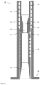
- a tube seal device 20 is depicted orientated vertically and arranged for downflow though the device in accordance with the embodiment depicted in Figure 1 .
- the tube seal device 20 comprises an outer seal tube 21 and an inner tube 22.
- the inner tube 21 is located inside the seal tube 22 to provide an overlapping region and is free to slide vertically.
- the inner tube 22 is fixed to a lowermost portion 30 of a heat exchange tube.
- the lowermost portion of the heat exchange tube 30 and connected part of the inner tube 22 have an internal diameter of 25 mm and are free of catalyst.
- the inner tube 22 tapers from the internal diameter of 25 mm to a constriction 31 of 12 mm internal diameter and expands from the constriction 31 to a low-pressure region 32 of 18 mm internal diameter and 108 mm length.
- the inner tube flares from the 18 mm diameter of the low-pressure region 32 to 31 mm external diameter in an expansion region 33 over a length of 78 mm.
- Twelve passages 34 of 3 mm diameter are provided between the low-pressure region 32, downstream of the constriction 31, and an annular clearance gap 35 between the inner surface of the seal tube 21 and the outer surface of the inner tube 22.
- the thickness of the annular clearance gap 35 between seal tube 21 and the exterior surface of the inner tube 22 is 0.2 mm.
- the seal tube 21 comprises seven parallel 7mm wide square-cut grooves 36 cut into the inner surface of the seal tube 21 facing the inner tube 22 in the overlapping region.
- the grooves extend from a position in the low pressure region 32 adjacent the passages 34 upwards towards and beyond where the inner tube 22 is connected to the lowermost portion 30 of the heat exchange tubes. It may be seen that providing the grooves in this way allows for a greater number to be present than if they were cut onto the exterior surface of the inner tube 22.
- a further six parallel 7mm wide square-cut grooves 37 are cut into the exterior surface of the inner tube 22 from a position adjacent the passages 34 downwards towards the expansion region 33.
- the lengths of the inner tube 22 and seal tube 21 are such that the passages 34 and open ends of the inner tube 22 are within the seal tubes 21 both at start up, i.e. with the apparatus at ambient temperature and at normal operating temperature.
- a flange 38 is provided on a lowermost portion of the seal tube 21, beyond the end of the overlapping region, to enable fixing of the tube seal device 20 to a tubesheet.
Landscapes
- Chemical & Material Sciences (AREA)
- Engineering & Computer Science (AREA)
- Chemical Kinetics & Catalysis (AREA)
- Organic Chemistry (AREA)
- Physics & Mathematics (AREA)
- Thermal Sciences (AREA)
- Mechanical Engineering (AREA)
- General Engineering & Computer Science (AREA)
- Health & Medical Sciences (AREA)
- General Health & Medical Sciences (AREA)
- Combustion & Propulsion (AREA)
- Inorganic Chemistry (AREA)
- Heat-Exchange Devices With Radiators And Conduit Assemblies (AREA)
- Hydrogen, Water And Hydrids (AREA)
- Devices And Processes Conducted In The Presence Of Fluids And Solid Particles (AREA)
- Physical Or Chemical Processes And Apparatus (AREA)
Applications Claiming Priority (2)
| Application Number | Priority Date | Filing Date | Title |
|---|---|---|---|
| GBGB2102787.5A GB202102787D0 (en) | 2021-02-26 | 2021-02-26 | Heat exchange reactor seal apparatus |
| PCT/GB2022/050318 WO2022180354A1 (en) | 2021-02-26 | 2022-02-08 | Heat exchange reactor seal apparatus |
Publications (2)
| Publication Number | Publication Date |
|---|---|
| EP4298392A1 EP4298392A1 (en) | 2024-01-03 |
| EP4298392B1 true EP4298392B1 (en) | 2025-06-25 |
Family
ID=75267527
Family Applications (1)
| Application Number | Title | Priority Date | Filing Date |
|---|---|---|---|
| EP22704413.8A Active EP4298392B1 (en) | 2021-02-26 | 2022-02-08 | Heat exchange reactor seal apparatus |
Country Status (13)
| Country | Link |
|---|---|
| US (1) | US20240035758A1 (https=) |
| EP (1) | EP4298392B1 (https=) |
| JP (1) | JP2024517531A (https=) |
| KR (1) | KR20230150259A (https=) |
| CN (1) | CN116802452A (https=) |
| AU (1) | AU2022227218A1 (https=) |
| BR (1) | BR112023015717A2 (https=) |
| CA (1) | CA3201229A1 (https=) |
| DK (1) | DK4298392T3 (https=) |
| GB (2) | GB202102787D0 (https=) |
| MX (1) | MX2023007647A (https=) |
| SA (1) | SA523441258B1 (https=) |
| WO (1) | WO2022180354A1 (https=) |
Families Citing this family (1)
| Publication number | Priority date | Publication date | Assignee | Title |
|---|---|---|---|---|
| WO2025052087A1 (en) | 2023-09-08 | 2025-03-13 | Johnson Matthey Davy Technologies Limited | Method of forming a syngas |
Family Cites Families (3)
| Publication number | Priority date | Publication date | Assignee | Title |
|---|---|---|---|---|
| GB9516125D0 (en) | 1995-08-07 | 1995-10-04 | Ici Plc | Heat exchange apparatus and process |
| AU4733199A (en) * | 1998-09-04 | 2000-03-16 | Linde Aktiengesellschaft | Process and primary reformer for generating synthesis gas |
| GB0001540D0 (en) * | 2000-01-25 | 2000-03-15 | Gratwick Christopher | Stream reforming |
-
2021
- 2021-02-26 GB GBGB2102787.5A patent/GB202102787D0/en not_active Ceased
-
2022
- 2022-02-08 GB GB2201566.3A patent/GB2604738B/en active Active
- 2022-02-08 CA CA3201229A patent/CA3201229A1/en active Pending
- 2022-02-08 KR KR1020237025256A patent/KR20230150259A/ko active Pending
- 2022-02-08 DK DK22704413.8T patent/DK4298392T3/da active
- 2022-02-08 EP EP22704413.8A patent/EP4298392B1/en active Active
- 2022-02-08 US US18/255,970 patent/US20240035758A1/en active Pending
- 2022-02-08 CN CN202280012015.2A patent/CN116802452A/zh active Pending
- 2022-02-08 BR BR112023015717A patent/BR112023015717A2/pt unknown
- 2022-02-08 AU AU2022227218A patent/AU2022227218A1/en active Pending
- 2022-02-08 WO PCT/GB2022/050318 patent/WO2022180354A1/en not_active Ceased
- 2022-02-08 JP JP2023532785A patent/JP2024517531A/ja active Pending
- 2022-02-08 MX MX2023007647A patent/MX2023007647A/es unknown
-
2023
- 2023-06-15 SA SA523441258A patent/SA523441258B1/ar unknown
Also Published As
| Publication number | Publication date |
|---|---|
| AU2022227218A9 (en) | 2024-10-10 |
| GB2604738A (en) | 2022-09-14 |
| BR112023015717A2 (pt) | 2023-10-10 |
| CN116802452A (zh) | 2023-09-22 |
| CA3201229A1 (en) | 2022-09-01 |
| DK4298392T3 (da) | 2025-07-14 |
| US20240035758A1 (en) | 2024-02-01 |
| MX2023007647A (es) | 2023-07-07 |
| SA523441258B1 (ar) | 2024-02-08 |
| EP4298392A1 (en) | 2024-01-03 |
| KR20230150259A (ko) | 2023-10-30 |
| GB2604738B (en) | 2023-05-10 |
| GB202102787D0 (en) | 2021-04-14 |
| AU2022227218A1 (en) | 2023-06-29 |
| JP2024517531A (ja) | 2024-04-23 |
| WO2022180354A1 (en) | 2022-09-01 |
Similar Documents
| Publication | Publication Date | Title |
|---|---|---|
| US9227844B2 (en) | Heat exchange reformer with double-tubes for reforming hydrocarbons | |
| AU597362B2 (en) | Process and apparatus for the production of synthesis gas | |
| EP0535505B1 (en) | Reactor for carrying out non-adiabatic catalytic reactions | |
| US4830834A (en) | Reactor for the catalytic reforming of hydrocarbons | |
| EP0895806B1 (en) | A process for conducting endothermic reactions | |
| KR20120036891A (ko) | 쉘 앤드 튜브 반응기 | |
| AU2003248394B2 (en) | Process and apparatus for the preparation of synthesis gas | |
| AU2003248392B2 (en) | Process and apparatus for the preparation of synthesis gas | |
| JPH0522641B2 (https=) | ||
| CN105771812A (zh) | 重整烃的方法 | |
| US5429809A (en) | Process and reactor for carrying out non-adiabatic catalytic reactions | |
| AU2019321072B2 (en) | Steam or dry reforming of hydrocarbons | |
| EP4298392B1 (en) | Heat exchange reactor seal apparatus | |
| US9776861B1 (en) | Method of steam methane reforming with a tube and shell reactor having spirally positioned fluid inlets | |
| WO2003031050A1 (en) | Heat exchange reactor | |
| US20180327262A1 (en) | Method and apparatus for producing synthesis gas | |
| EP1063008A2 (en) | Reactor for carrying out a non-adiabatic process | |
| GB2075859A (en) | Catalytic reactor with internal heat exchanger | |
| KR102917230B1 (ko) | 반응기 튜브 조립체 | |
| RU2664138C1 (ru) | Компактный реактор для получения синтез-газа из природного/попутного газа в процессе автотермического риформинга |
Legal Events
| Date | Code | Title | Description |
|---|---|---|---|
| STAA | Information on the status of an ep patent application or granted ep patent |
Free format text: STATUS: UNKNOWN |
|
| STAA | Information on the status of an ep patent application or granted ep patent |
Free format text: STATUS: THE INTERNATIONAL PUBLICATION HAS BEEN MADE |
|
| PUAI | Public reference made under article 153(3) epc to a published international application that has entered the european phase |
Free format text: ORIGINAL CODE: 0009012 |
|
| STAA | Information on the status of an ep patent application or granted ep patent |
Free format text: STATUS: REQUEST FOR EXAMINATION WAS MADE |
|
| 17P | Request for examination filed |
Effective date: 20230824 |
|
| AK | Designated contracting states |
Kind code of ref document: A1 Designated state(s): AL AT BE BG CH CY CZ DE DK EE ES FI FR GB GR HR HU IE IS IT LI LT LU LV MC MK MT NL NO PL PT RO RS SE SI SK SM TR |
|
| DAV | Request for validation of the european patent (deleted) | ||
| DAX | Request for extension of the european patent (deleted) | ||
| RAP3 | Party data changed (applicant data changed or rights of an application transferred) |
Owner name: JOHNSON MATTHEY PUBLIC LIMITED COMPANY |
|
| GRAP | Despatch of communication of intention to grant a patent |
Free format text: ORIGINAL CODE: EPIDOSNIGR1 |
|
| STAA | Information on the status of an ep patent application or granted ep patent |
Free format text: STATUS: GRANT OF PATENT IS INTENDED |
|
| GRAS | Grant fee paid |
Free format text: ORIGINAL CODE: EPIDOSNIGR3 |
|
| INTG | Intention to grant announced |
Effective date: 20250424 |
|
| GRAA | (expected) grant |
Free format text: ORIGINAL CODE: 0009210 |
|
| STAA | Information on the status of an ep patent application or granted ep patent |
Free format text: STATUS: THE PATENT HAS BEEN GRANTED |
|
| AK | Designated contracting states |
Kind code of ref document: B1 Designated state(s): AL AT BE BG CH CY CZ DE DK EE ES FI FR GR HR HU IE IS IT LI LT LU LV MC MK MT NL NO PL PT RO RS SE SI SK SM TR |
|
| RBV | Designated contracting states (corrected) |
Designated state(s): AL AT BE BG CH CY CZ DE DK EE ES FI FR GR HR HU IE IS IT LI LT LU LV MC MK MT NL NO PL PT RO RS SE SI SK SM TR |
|
| REG | Reference to a national code |
Ref country code: CH Ref legal event code: EP |
|
| REG | Reference to a national code |
Ref country code: DK Ref legal event code: T3 Effective date: 20250703 |
|
| REG | Reference to a national code |
Ref country code: CH Ref legal event code: EP |
|
| REG | Reference to a national code |
Ref country code: IE Ref legal event code: FG4D |
|
| REG | Reference to a national code |
Ref country code: DE Ref legal event code: R096 Ref document number: 602022016413 Country of ref document: DE |
|
| P01 | Opt-out of the competence of the unified patent court (upc) registered |
Free format text: CASE NUMBER: APP_30678/2025 Effective date: 20250626 |
|
| REG | Reference to a national code |
Ref country code: NL Ref legal event code: FP |
|
| REG | Reference to a national code |
Ref country code: CH Ref legal event code: W10 Free format text: ST27 STATUS EVENT CODE: U-0-0-W10-W00 (AS PROVIDED BY THE NATIONAL OFFICE) Effective date: 20251008 |
|
| PG25 | Lapsed in a contracting state [announced via postgrant information from national office to epo] |
Ref country code: FI Free format text: LAPSE BECAUSE OF FAILURE TO SUBMIT A TRANSLATION OF THE DESCRIPTION OR TO PAY THE FEE WITHIN THE PRESCRIBED TIME-LIMIT Effective date: 20250625 |
|
| REG | Reference to a national code |
Ref country code: LT Ref legal event code: MG9D |
|
| PG25 | Lapsed in a contracting state [announced via postgrant information from national office to epo] |
Ref country code: GR Free format text: LAPSE BECAUSE OF FAILURE TO SUBMIT A TRANSLATION OF THE DESCRIPTION OR TO PAY THE FEE WITHIN THE PRESCRIBED TIME-LIMIT Effective date: 20250926 |
|
| PG25 | Lapsed in a contracting state [announced via postgrant information from national office to epo] |
Ref country code: BG Free format text: LAPSE BECAUSE OF FAILURE TO SUBMIT A TRANSLATION OF THE DESCRIPTION OR TO PAY THE FEE WITHIN THE PRESCRIBED TIME-LIMIT Effective date: 20250625 |
|
| PG25 | Lapsed in a contracting state [announced via postgrant information from national office to epo] |
Ref country code: HR Free format text: LAPSE BECAUSE OF FAILURE TO SUBMIT A TRANSLATION OF THE DESCRIPTION OR TO PAY THE FEE WITHIN THE PRESCRIBED TIME-LIMIT Effective date: 20250625 |
|
| PG25 | Lapsed in a contracting state [announced via postgrant information from national office to epo] |
Ref country code: RS Free format text: LAPSE BECAUSE OF FAILURE TO SUBMIT A TRANSLATION OF THE DESCRIPTION OR TO PAY THE FEE WITHIN THE PRESCRIBED TIME-LIMIT Effective date: 20250925 |
|
| PG25 | Lapsed in a contracting state [announced via postgrant information from national office to epo] |
Ref country code: LV Free format text: LAPSE BECAUSE OF FAILURE TO SUBMIT A TRANSLATION OF THE DESCRIPTION OR TO PAY THE FEE WITHIN THE PRESCRIBED TIME-LIMIT Effective date: 20250625 |
|
| RAP2 | Party data changed (patent owner data changed or rights of a patent transferred) |
Owner name: JOHNSON MATTHEY DAVY TECHNOLOGIES LIMITED |
|
| REG | Reference to a national code |
Ref country code: DE Ref legal event code: R081 Ref document number: 602022016413 Country of ref document: DE Owner name: JOHNSON MATTHEY DAVY TECHNOLOGIES LIMITED, GB Free format text: FORMER OWNER: JOHNSON MATTHEY PUBLIC LIMITED COMPANY, LONDON, GB |
|
| PG25 | Lapsed in a contracting state [announced via postgrant information from national office to epo] |
Ref country code: PT Free format text: LAPSE BECAUSE OF FAILURE TO SUBMIT A TRANSLATION OF THE DESCRIPTION OR TO PAY THE FEE WITHIN THE PRESCRIBED TIME-LIMIT Effective date: 20251027 |
|
| REG | Reference to a national code |
Ref country code: AT Ref legal event code: MK05 Ref document number: 1806809 Country of ref document: AT Kind code of ref document: T Effective date: 20250625 |
|
| REG | Reference to a national code |
Ref country code: NL Ref legal event code: PD Owner name: JOHNSON MATTHEY DAVY TECHNOLOGIES LIMITED; GB Free format text: DETAILS ASSIGNMENT: CHANGE OF OWNER(S), ASSIGNMENT; FORMER OWNER NAME: JOHNSON MATTHEY PUBLIC LIMITED COMPANY Effective date: 20251210 |
|
| PG25 | Lapsed in a contracting state [announced via postgrant information from national office to epo] |
Ref country code: IS Free format text: LAPSE BECAUSE OF FAILURE TO SUBMIT A TRANSLATION OF THE DESCRIPTION OR TO PAY THE FEE WITHIN THE PRESCRIBED TIME-LIMIT Effective date: 20251025 |
|
| PG25 | Lapsed in a contracting state [announced via postgrant information from national office to epo] |
Ref country code: AT Free format text: LAPSE BECAUSE OF FAILURE TO SUBMIT A TRANSLATION OF THE DESCRIPTION OR TO PAY THE FEE WITHIN THE PRESCRIBED TIME-LIMIT Effective date: 20250625 Ref country code: SM Free format text: LAPSE BECAUSE OF FAILURE TO SUBMIT A TRANSLATION OF THE DESCRIPTION OR TO PAY THE FEE WITHIN THE PRESCRIBED TIME-LIMIT Effective date: 20250625 |
|
| PG25 | Lapsed in a contracting state [announced via postgrant information from national office to epo] |
Ref country code: CZ Free format text: LAPSE BECAUSE OF FAILURE TO SUBMIT A TRANSLATION OF THE DESCRIPTION OR TO PAY THE FEE WITHIN THE PRESCRIBED TIME-LIMIT Effective date: 20250625 |
|
| PG25 | Lapsed in a contracting state [announced via postgrant information from national office to epo] |
Ref country code: PL Free format text: LAPSE BECAUSE OF FAILURE TO SUBMIT A TRANSLATION OF THE DESCRIPTION OR TO PAY THE FEE WITHIN THE PRESCRIBED TIME-LIMIT Effective date: 20250625 |
|
| PG25 | Lapsed in a contracting state [announced via postgrant information from national office to epo] |
Ref country code: EE Free format text: LAPSE BECAUSE OF FAILURE TO SUBMIT A TRANSLATION OF THE DESCRIPTION OR TO PAY THE FEE WITHIN THE PRESCRIBED TIME-LIMIT Effective date: 20250625 |
|
| PG25 | Lapsed in a contracting state [announced via postgrant information from national office to epo] |
Ref country code: SK Free format text: LAPSE BECAUSE OF FAILURE TO SUBMIT A TRANSLATION OF THE DESCRIPTION OR TO PAY THE FEE WITHIN THE PRESCRIBED TIME-LIMIT Effective date: 20250625 |
|
| PG25 | Lapsed in a contracting state [announced via postgrant information from national office to epo] |
Ref country code: ES Free format text: LAPSE BECAUSE OF FAILURE TO SUBMIT A TRANSLATION OF THE DESCRIPTION OR TO PAY THE FEE WITHIN THE PRESCRIBED TIME-LIMIT Effective date: 20250625 |
|
| REG | Reference to a national code |
Ref country code: BE Ref legal event code: PD Owner name: JOHNSON MATTHEY DAVY TECHNOLOGIES LIMITED; GB Free format text: DETAILS ASSIGNMENT: CHANGE OF OWNER(S), ASSIGNMENT; FORMER OWNER NAME: JOHNSON MATTHEY PUBLIC LIMITED COMPANY Effective date: 20251231 |
|
| PGFP | Annual fee paid to national office [announced via postgrant information from national office to epo] |
Ref country code: NL Payment date: 20260121 Year of fee payment: 5 |
|
| PGFP | Annual fee paid to national office [announced via postgrant information from national office to epo] |
Ref country code: NO Payment date: 20260123 Year of fee payment: 5 Ref country code: DK Payment date: 20260121 Year of fee payment: 5 Ref country code: DE Payment date: 20260121 Year of fee payment: 5 |
|
| PGFP | Annual fee paid to national office [announced via postgrant information from national office to epo] |
Ref country code: BE Payment date: 20260121 Year of fee payment: 5 Ref country code: IT Payment date: 20260121 Year of fee payment: 5 |
|
| PGFP | Annual fee paid to national office [announced via postgrant information from national office to epo] |
Ref country code: FR Payment date: 20260121 Year of fee payment: 5 |
|
| PGFP | Annual fee paid to national office [announced via postgrant information from national office to epo] |
Ref country code: TR Payment date: 20260127 Year of fee payment: 5 |
|
| PLBE | No opposition filed within time limit |
Free format text: ORIGINAL CODE: 0009261 |
|
| STAA | Information on the status of an ep patent application or granted ep patent |
Free format text: STATUS: NO OPPOSITION FILED WITHIN TIME LIMIT |