EP4297942B1 - Automatisierte systeme und verfahren für fachwerkanordnungen bei der konstruktion von modularen gebäuden - Google Patents
Automatisierte systeme und verfahren für fachwerkanordnungen bei der konstruktion von modularen gebäuden Download PDFInfo
- Publication number
- EP4297942B1 EP4297942B1 EP22714950.7A EP22714950A EP4297942B1 EP 4297942 B1 EP4297942 B1 EP 4297942B1 EP 22714950 A EP22714950 A EP 22714950A EP 4297942 B1 EP4297942 B1 EP 4297942B1
- Authority
- EP
- European Patent Office
- Prior art keywords
- truss
- finished
- station
- angled
- webs
- Prior art date
- Legal status (The legal status is an assumption and is not a legal conclusion. Google has not performed a legal analysis and makes no representation as to the accuracy of the status listed.)
- Active
Links
Images


Classifications
-
- B—PERFORMING OPERATIONS; TRANSPORTING
- B27—WORKING OR PRESERVING WOOD OR SIMILAR MATERIAL; NAILING OR STAPLING MACHINES IN GENERAL
- B27B—SAWS FOR WOOD OR SIMILAR MATERIAL; COMPONENTS OR ACCESSORIES THEREFOR
- B27B5/00—Sawing machines working with circular or cylindrical saw blades; Components or equipment therefor
- B27B5/02—Sawing machines working with circular or cylindrical saw blades; Components or equipment therefor characterised by a special purpose only
-
- B—PERFORMING OPERATIONS; TRANSPORTING
- B27—WORKING OR PRESERVING WOOD OR SIMILAR MATERIAL; NAILING OR STAPLING MACHINES IN GENERAL
- B27F—DOVETAILED WORK; TENONS; SLOTTING MACHINES FOR WOOD OR SIMILAR MATERIAL; NAILING OR STAPLING MACHINES
- B27F7/00—Nailing or stapling; Nailed or stapled work
- B27F7/15—Machines for driving in nail- plates and spiked fittings
- B27F7/155—Machines for driving in nail- plates and spiked fittings for nail plates
-
- B—PERFORMING OPERATIONS; TRANSPORTING
- B27—WORKING OR PRESERVING WOOD OR SIMILAR MATERIAL; NAILING OR STAPLING MACHINES IN GENERAL
- B27M—WORKING OF WOOD NOT PROVIDED FOR IN SUBCLASSES B27B - B27L; MANUFACTURE OF SPECIFIC WOODEN ARTICLES
- B27M1/00—Working of wood not provided for in subclasses B27B - B27L, e.g. by stretching
- B27M1/08—Working of wood not provided for in subclasses B27B - B27L, e.g. by stretching by multi-step processes
-
- B—PERFORMING OPERATIONS; TRANSPORTING
- B27—WORKING OR PRESERVING WOOD OR SIMILAR MATERIAL; NAILING OR STAPLING MACHINES IN GENERAL
- B27M—WORKING OF WOOD NOT PROVIDED FOR IN SUBCLASSES B27B - B27L; MANUFACTURE OF SPECIFIC WOODEN ARTICLES
- B27M3/00—Manufacture or reconditioning of specific semi-finished or finished articles
- B27M3/0013—Manufacture or reconditioning of specific semi-finished or finished articles of composite or compound articles
- B27M3/0073—Manufacture or reconditioning of specific semi-finished or finished articles of composite or compound articles characterised by nailing, stapling or screwing connections
-
- B—PERFORMING OPERATIONS; TRANSPORTING
- B27—WORKING OR PRESERVING WOOD OR SIMILAR MATERIAL; NAILING OR STAPLING MACHINES IN GENERAL
- B27M—WORKING OF WOOD NOT PROVIDED FOR IN SUBCLASSES B27B - B27L; MANUFACTURE OF SPECIFIC WOODEN ARTICLES
- B27M3/00—Manufacture or reconditioning of specific semi-finished or finished articles
- B27M3/0093—Manufacture or reconditioning of specific semi-finished or finished articles of raised panels, i.e. panels having a profiled surface
-
- B—PERFORMING OPERATIONS; TRANSPORTING
- B27—WORKING OR PRESERVING WOOD OR SIMILAR MATERIAL; NAILING OR STAPLING MACHINES IN GENERAL
- B27M—WORKING OF WOOD NOT PROVIDED FOR IN SUBCLASSES B27B - B27L; MANUFACTURE OF SPECIFIC WOODEN ARTICLES
- B27M3/00—Manufacture or reconditioning of specific semi-finished or finished articles
- B27M3/02—Manufacture or reconditioning of specific semi-finished or finished articles of roofing elements, e.g. shingles
-
- E—FIXED CONSTRUCTIONS
- E04—BUILDING
- E04C—STRUCTURAL ELEMENTS; BUILDING MATERIALS
- E04C3/00—Structural elongated elements designed for load-supporting
- E04C3/02—Joists; Girders, trusses, or trusslike structures, e.g. prefabricated; Lintels; Transoms; Braces
- E04C3/12—Joists; Girders, trusses, or trusslike structures, e.g. prefabricated; Lintels; Transoms; Braces of wood, e.g. with reinforcements, with tensioning members
- E04C3/16—Joists; Girders, trusses, or trusslike structures, e.g. prefabricated; Lintels; Transoms; Braces of wood, e.g. with reinforcements, with tensioning members with apertured web, e.g. trusses
-
- E—FIXED CONSTRUCTIONS
- E04—BUILDING
- E04C—STRUCTURAL ELEMENTS; BUILDING MATERIALS
- E04C3/00—Structural elongated elements designed for load-supporting
- E04C3/02—Joists; Girders, trusses, or trusslike structures, e.g. prefabricated; Lintels; Transoms; Braces
- E04C3/12—Joists; Girders, trusses, or trusslike structures, e.g. prefabricated; Lintels; Transoms; Braces of wood, e.g. with reinforcements, with tensioning members
- E04C3/17—Joists; Girders, trusses, or trusslike structures, e.g. prefabricated; Lintels; Transoms; Braces of wood, e.g. with reinforcements, with tensioning members with non-parallel upper and lower edges, e.g. roof trusses
-
- E—FIXED CONSTRUCTIONS
- E04—BUILDING
- E04C—STRUCTURAL ELEMENTS; BUILDING MATERIALS
- E04C3/00—Structural elongated elements designed for load-supporting
- E04C3/02—Joists; Girders, trusses, or trusslike structures, e.g. prefabricated; Lintels; Transoms; Braces
- E04C3/04—Joists; Girders, trusses, or trusslike structures, e.g. prefabricated; Lintels; Transoms; Braces of metal
- E04C2003/0486—Truss like structures composed of separate truss elements
-
- E—FIXED CONSTRUCTIONS
- E04—BUILDING
- E04H—BUILDINGS OR LIKE STRUCTURES FOR PARTICULAR PURPOSES; SWIMMING OR SPLASH BATHS OR POOLS; MASTS; FENCING; TENTS OR CANOPIES, IN GENERAL
- E04H12/00—Towers; Masts or poles; Chimney stacks; Water-towers; Methods of erecting such structures
- E04H12/02—Structures made of specified materials
- E04H12/04—Structures made of specified materials of wood
- E04H12/06—Truss-like structures
-
- G—PHYSICS
- G05—CONTROLLING; REGULATING
- G05B—CONTROL OR REGULATING SYSTEMS IN GENERAL; FUNCTIONAL ELEMENTS OF SUCH SYSTEMS; MONITORING OR TESTING ARRANGEMENTS FOR SUCH SYSTEMS OR ELEMENTS
- G05B2219/00—Program-control systems
- G05B2219/30—Nc systems
- G05B2219/45—Nc applications
- G05B2219/45211—Making, assembling truss structures
-
- Y—GENERAL TAGGING OF NEW TECHNOLOGICAL DEVELOPMENTS; GENERAL TAGGING OF CROSS-SECTIONAL TECHNOLOGIES SPANNING OVER SEVERAL SECTIONS OF THE IPC; TECHNICAL SUBJECTS COVERED BY FORMER USPC CROSS-REFERENCE ART COLLECTIONS [XRACs] AND DIGESTS
- Y10—TECHNICAL SUBJECTS COVERED BY FORMER USPC
- Y10T—TECHNICAL SUBJECTS COVERED BY FORMER US CLASSIFICATION
- Y10T29/00—Metal working
- Y10T29/49—Method of mechanical manufacture
- Y10T29/49616—Structural member making
- Y10T29/49623—Static structure, e.g., a building component
- Y10T29/49625—Openwork, e.g., a truss, joist, frame, lattice-type or box beam
-
- Y—GENERAL TAGGING OF NEW TECHNOLOGICAL DEVELOPMENTS; GENERAL TAGGING OF CROSS-SECTIONAL TECHNOLOGIES SPANNING OVER SEVERAL SECTIONS OF THE IPC; TECHNICAL SUBJECTS COVERED BY FORMER USPC CROSS-REFERENCE ART COLLECTIONS [XRACs] AND DIGESTS
- Y10—TECHNICAL SUBJECTS COVERED BY FORMER USPC
- Y10T—TECHNICAL SUBJECTS COVERED BY FORMER US CLASSIFICATION
- Y10T29/00—Metal working
- Y10T29/53—Means to assemble or disassemble
- Y10T29/53961—Means to assemble or disassemble with work-holder for assembly
- Y10T29/5397—Means to assemble or disassemble with work-holder for assembly and assembling press [e.g., truss assembling means, etc.]
Definitions
- the subject matter disclosed herein relates generally to the construction of modular construction units.
- the invention relates to an automated system for manufacturing truss elements for use in modular construction units according to the preamble of claim 1, as well as a method for the automated manufacture of such truss elements according to the preamble of claim 10.
- Such a system and such a method are known from document US2008/0172983 A1 .
- an automated system for manufacturing truss elements for use in modular construction units comprising an angled web grouping of stations configured to receive and cut dimensional lumber to form angled webs for use in assembly of the truss elements; an upright web grouping of stations configured to receive and cut dimensional lumber to form upright webs for use in assembly of the truss elements; a truss chord grouping of stations configured to receive and cut dimensional lumber to form truss chords for use in assembly of the truss elements; a finished lumber merge/transfer station, which is configured to receive the angled webs from the angled web grouping of stations, the upright webs from the upright web grouping of stations, and the truss chords from the truss chord grouping of stations, and to transfer the angled webs, the upright webs, and the truss chords onto an assembly jig at a finished lumber jig placement station; a bottom nail plate (BNP) grouping of stations configured to
- an automated system for manufacturing truss elements for use in modular construction units comprising an angled web grouping of stations configured to receive and cut dimensional lumber to form angled webs for use in assembly of the truss elements; an upright web grouping of stations configured to receive and cut dimensional lumber to form upright webs for use in assembly of the truss elements; a truss chord grouping of stations configured to receive and cut dimensional lumber to form truss chords for use in assembly of the truss elements; a finished lumber merge/transfer station, which is configured to receive the angled webs from the angled web grouping of stations, the upright webs from the upright web grouping of stations, and the truss chords from the truss chord grouping of stations, and to transfer the angled webs, the upright webs, and the truss chords onto an assembly jig at a finished lumber jig placement station; a bottom nail plate (BNP) grouping of stations configured to
- a method for automated manufacture of truss elements for use in modular construction units comprising: receiving and cutting, at an angled web grouping of stations, dimensional lumber to form angled webs for use in assembly of the truss elements; receiving and cutting, at an upright web grouping of stations, dimensional lumber to form upright webs for use in assembly of the truss elements; receiving and cutting, at a truss chord grouping of stations, dimensional lumber to form truss chords for use in assembly of the truss elements; receiving, at a finished lumber merge/transfer station, the angled webs from the angled web grouping of stations, the upright webs from the upright web grouping of stations, and the truss chords from the truss chord grouping of stations; transferring, at the finished lumber merge/transfer station, the angled webs, the upright webs, and the truss chords onto an assembly jig at a finished lumber jig placement station; receiving and positioning
- a method for automated manufacture of truss elements for use in modular construction units comprising: receiving and cutting, at an angled web grouping of stations, dimensional lumber to form angled webs for use in assembly of the truss elements; receiving and cutting, at an upright web grouping of stations, dimensional lumber to form upright webs for use in assembly of the truss elements; receiving and cutting, at a truss chord grouping of stations, dimensional lumber to form truss chords for use in assembly of the truss elements; receiving, at a finished lumber merge/transfer station, the angled webs from the angled web grouping of stations, the upright webs from the upright web grouping of stations, and the truss chords from the truss chord grouping of stations; transferring, at the finished lumber merge/transfer station, the angled webs, the upright webs, and the truss chords onto an assembly jig at a finished lumber jig placement station; receiving and positioning
- a method for automated manufacture of truss elements for use in modular construction units comprising: receiving and cutting, at an angled web grouping of stations, dimensional lumber to form angled webs for use in assembly of the truss elements; receiving and cutting, at an upright web grouping of stations, dimensional lumber to form upright webs for use in assembly of the truss elements; receiving and cutting, at a truss chord grouping of stations, dimensional lumber to form truss chords for use in assembly of the truss elements; receiving, at a finished lumber merge/transfer station, the angled webs from the angled web grouping of stations, the upright webs from the upright web grouping of stations, and the truss chords from the truss chord grouping of stations; transferring, at the finished lumber merge/transfer station, the angled webs, the upright webs, and the truss chords onto an assembly jig at a finished lumber jig placement station; receiving and positioning
- a method for automated manufacture of truss elements for use in modular construction units comprising: receiving and cutting, at an angled web grouping of stations, dimensional lumber to form angled webs for use in assembly of the truss elements; receiving and cutting, at an upright web grouping of stations, dimensional lumber to form upright webs for use in assembly of the truss elements; receiving and cutting, at a truss chord grouping of stations, dimensional lumber to form truss chords for use in assembly of the truss elements; receiving, at a finished lumber merge/transfer station, the angled webs from the angled web grouping of stations, the upright webs from the upright web grouping of stations, and the truss chords from the truss chord grouping of stations; transferring, at the finished lumber merge/transfer station, the angled webs, the upright webs, and the truss chords onto an assembly jig at a finished lumber jig placement station; receiving and positioning
- a method for automated manufacture of truss elements for use in modular construction units comprising: receiving and cutting, at an angled web grouping of stations, dimensional lumber to form angled webs for use in assembly of the truss elements; receiving and cutting, at an upright web grouping of stations, dimensional lumber to form upright webs for use in assembly of the truss elements; receiving and cutting, at a truss chord grouping of stations, dimensional lumber to form truss chords for use in assembly of the truss elements; receiving, at a finished lumber merge/transfer station, the angled webs from the angled web grouping of stations, the upright webs from the upright web grouping of stations, and the truss chords from the truss chord grouping of stations; transferring, at the finished lumber merge/transfer station, the angled webs, the upright webs, and the truss chords onto an assembly jig at a finished lumber jig placement station; receiving and positioning
- a method for automated manufacture of truss elements for use in modular construction units comprising: receiving and cutting, at an angled web grouping of stations, dimensional lumber to form angled webs for use in assembly of the truss elements; receiving and cutting, at an upright web grouping of stations, dimensional lumber to form upright webs for use in assembly of the truss elements; receiving and cutting, at a truss chord grouping of stations, dimensional lumber to form truss chords for use in assembly of the truss elements; receiving, at a finished lumber merge/transfer station, the angled webs from the angled web grouping of stations, the upright webs from the upright web grouping of stations, and the truss chords from the truss chord grouping of stations; transferring, at the finished lumber merge/transfer station, the angled webs, the upright webs, and the truss chords onto an assembly jig at a finished lumber jig placement station; receiving and positioning
- a method for automated manufacture of truss elements for use in modular construction units comprising: receiving and cutting, at an angled web grouping of stations, dimensional lumber to form angled webs for use in assembly of the truss elements; receiving and cutting, at an upright web grouping of stations, dimensional lumber to form upright webs for use in assembly of the truss elements; receiving and cutting, at a truss chord grouping of stations, dimensional lumber to form truss chords for use in assembly of the truss elements; receiving, at a finished lumber merge/transfer station, the angled webs from the angled web grouping of stations, the upright webs from the upright web grouping of stations, and the truss chords from the truss chord grouping of stations; transferring, at the finished lumber merge/transfer station, the angled webs, the upright webs, and the truss chords onto an assembly jig at a finished lumber jig placement station; receiving and positioning
- a method for automated manufacture of truss elements for use in modular construction units comprising: receiving and cutting, at an angled web grouping of stations, dimensional lumber to form angled webs for use in assembly of the truss elements; receiving and cutting, at an upright web grouping of stations, dimensional lumber to form upright webs for use in assembly of the truss elements; receiving and cutting, at a truss chord grouping of stations, dimensional lumber to form truss chords for use in assembly of the truss elements; receiving, at a finished lumber merge/transfer station, the angled webs from the angled web grouping of stations, the upright webs from the upright web grouping of stations, and the truss chords from the truss chord grouping of stations; transferring, at the finished lumber merge/transfer station, the angled webs, the upright webs, and the truss chords onto an assembly jig at a finished lumber jig placement station; receiving and positioning
- a method for automated manufacture of truss elements for use in modular construction units comprising: receiving and cutting, at an angled web grouping of stations, dimensional lumber to form angled webs for use in assembly of the truss elements; receiving and cutting, at an upright web grouping of stations, dimensional lumber to form upright webs for use in assembly of the truss elements; receiving and cutting, at a truss chord grouping of stations, dimensional lumber to form truss chords for use in assembly of the truss elements; receiving, at a finished lumber merge/transfer station, the angled webs from the angled web grouping of stations, the upright webs from the upright web grouping of stations, and the truss chords from the truss chord grouping of stations; transferring, at the finished lumber merge/transfer station, the angled webs, the upright webs, and the truss chords onto an assembly jig at a finished lumber jig placement station; receiving and positioning
- a method for automated manufacture of truss elements for use in modular construction units comprising: receiving and cutting, at an angled web grouping of stations, dimensional lumber to form angled webs for use in assembly of the truss elements; receiving and cutting, at an upright web grouping of stations, dimensional lumber to form upright webs for use in assembly of the truss elements; receiving and cutting, at a truss chord grouping of stations, dimensional lumber to form truss chords for use in assembly of the truss elements; receiving, at a finished lumber merge/transfer station, the angled webs from the angled web grouping of stations, the upright webs from the upright web grouping of stations, and the truss chords from the truss chord grouping of stations; transferring, at the finished lumber merge/transfer station, the angled webs, the upright webs, and the truss chords onto an assembly jig at a finished lumber jig placement station; receiving and positioning
- a method for automated manufacture of truss elements for use in modular construction units comprising: receiving and cutting, at an angled web grouping of stations, dimensional lumber to form angled webs for use in assembly of the truss elements; receiving and cutting, at an upright web grouping of stations, dimensional lumber to form upright webs for use in assembly of the truss elements; receiving and cutting, at a truss chord grouping of stations, dimensional lumber to form truss chords for use in assembly of the truss elements; receiving, at a finished lumber merge/transfer station, the angled webs from the angled web grouping of stations, the upright webs from the upright web grouping of stations, and the truss chords from the truss chord grouping of stations; transferring, at the finished lumber merge/transfer station, the angled webs, the upright webs, and the truss chords onto an assembly jig at a finished lumber jig placement station; receiving and positioning
- a method for automated manufacture of truss elements for use in modular construction units comprising: receiving and cutting, at an angled web grouping of stations, dimensional lumber to form angled webs for use in assembly of the truss elements; receiving and cutting, at an upright web grouping of stations, dimensional lumber to form upright webs for use in assembly of the truss elements; receiving and cutting, at a truss chord grouping of stations, dimensional lumber to form truss chords for use in assembly of the truss elements; receiving, at a finished lumber merge/transfer station, the angled webs from the angled web grouping of stations, the upright webs from the upright web grouping of stations, and the truss chords from the truss chord grouping of stations; transferring, at the finished lumber merge/transfer station, the angled webs, the upright webs, and the truss chords onto an assembly jig at a finished lumber jig placement station; receiving and positioning
- the terms "about” and “approximately,” when referring to a value or to a length, width, diameter, temperature, time, volume, concentration, percentage, etc., is meant to encompass variations of in some embodiments ⁇ 20%, in some embodiments ⁇ 10%, in some embodiments ⁇ 5%, in some embodiments ⁇ 1 %, in some embodiments ⁇ 0.5%, and in some embodiments ⁇ 0.1 % from the specified amount, as such variations are appropriate for the disclosed apparatuses and devices.
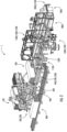
- FIGS. 1-20 A non-limiting example embodiment of a system and method for the automated manufacturing of trusses suitable for use in building modularly-constructed structures are disclosed herein. Reference may be made to FIGS. 1-20 for additional details regarding the presently disclosed systems and methods.
- the angled web loading station 100, the angled web rough cut station 200, the angled web finish cut station 300, and the angled web delivery station 400 collectively define what is referred to as the angled web production grouping.
- the upright web loading station 500, the upright web cut station 600, and the upright web delivery station 700 collectively define what is referred to as the upright web production grouping.
- the truss chord loading station 800, the truss chord cut station 900, and the truss chord delivery station 1000 collectively define what is referred to as the truss chord production grouping.
- the BNP loading station 1300 and the BNP delivery station 1400 collectively define what is referred to as the BNP grouping.
- the TNP loading station 1600 and the TNP delivery station 1700 collectively define what is referred to as the TNP grouping.
- the BNP jig placement station 1500, the finished lumber jig placement station 1200, the TNP jig placement station 1800, the nail plate press station 1900, and the finished truss unloading station 2000 collectively define the truss element assembly grouping.
- Each of the angled web production grouping, the upright web production grouping, and the truss chord production grouping output their respective types of finished lumber (e.g., finished angle webs 2, finished upright webs 3, and finished truss chords 4) into an area referred to as the finished lumber merge/transfer station 1100 for transfer onto an assembly jig 1 at the finished lumber jig placement station 1200.
- finished lumber e.g., finished angle webs 2, finished upright webs 3, and finished truss chords
- dimensional lumber DL e.g., a plurality of pieces of dimensional lumber that are delivered as a bundle
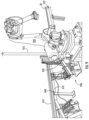
- the dimensional lumber DL is moved into a position on a conveyor 110 where the dimensional lumber DL is accessible by (e.g., can be picked up by) an automated robot 120.
- the automated robot 120 can be of any suitable type for grasping and manipulating one or more pieces of the dimensional lumber DL, but in the example embodiment discussed herein is a robotic arm with a grasping end effector (e.g., a grasping and/or suction mechanism) that is configured to detect a position of each piece of dimensional lumber DL on the conveyor 110, to lift the dimensional lumber DL off of the conveyor 110, and to transfer the dimensional lumber DL to the angled web rough cut station 200.
- the conveyor 110 receives the dimensional lumber DL from a dimensional lumber source (e.g., a crane, forklift, etc.) and transports the dimensional lumber DL into the position shown in FIG.
- a dimensional lumber source e.g., a crane, forklift, etc.
- the conveyor 110 may be of any type suitable for the transport of dimensional lumber DL in an automated manner into the position shown in FIG. 4 for manipulation by the robot 120.
- the robot 120 transfers (e.g., individually) the dimensional lumber DL from the conveyor 110 into an automated feed trough 210 of the angled web rough cut station 200.
- the angled web rough cut station 200 has a controller that receives as an input (e.g., from a measuring device, such as may be provided on the end effector of the robot 120) the length of the dimensional lumber DL deposited into the feed trough 210 by the robot 120.
- the angled web rough cut station 200 has a saw 220 (e.g., any suitable device for cutting dimensional lumber) that is movable vertically and/or laterally to cut the dimensional lumber DL into angled web segments having a prescribed length according to the design of the truss element being assembled by the system 1.
- the saw 220 has attached thereto a vacuum hose 225 for evacuation of sawdust and other particulate debris that is generated when the saw 220 is actuated (e.g., vertically and/or laterally, within the cross-section defined by the feed trough 210) for cutting the dimensional lumber DL in the feed trough 210 into the individual rough cut angled webs, which are then transferred onto the inlet conveyor for the cutting machine 310.
- the dimensional lumber DL is thus loaded into the feed trough 210 and is positionally registered (e.g., using one or more sensors).
- the controller then instructs the feed trough 210 to move (e.g., using a linear actuator) the dimensional lumber DL along the feed trough 210 by a prescribed distance.
- the dimensional lumber DL may be positionally registered within the feed trough 210 by advancing the dimensional lumber DL through the feed trough 210 to a location where the end of the dimensional lumber DL is detected at a point past the saw 220 where a sensor is located and the saw 220 may be actuated and retracted to cut the dimensional lumber DL, thereby ensuring a sufficiently square end of the dimensional lumber DL for the first angled web segment to be cut from the dimensional lumber DL and also establishing a zero, or "home,” position for the dimensional lumber DL within the feed trough 210.
- the controller then instructs the feed trough 210 to advance the dimensional lumber DL by a distance corresponding to (e.g., substantially the same as) a length of one of the angled webs used in the truss element being assembled.
- the lengths of the angled web segments may be different from each other, such as when the truss element being assembled comprises at least two angled webs of different lengths.
- the order in which the angled web segments is cut is known by the system 1 so that, when each finished angled web arrives at the finished lumber merge/transfer station 1100, the system 1 can ensure that the angled webs are each placed correctly on the assembly jig 10 (e.g., in the designated position on the assembly jig 10 for an angled web of a prescribed length) for the truss element being assembled.
- Each BNP is positioned on the assembly jig 10 in a designated location by one of the robots 1410, based on instructions received (e.g., from a controller) by the robot 1410 dictating the placement positions of each of the BNPs on the jig assembly 10 for the truss element being assembled.
- the BNP staging areas 1420 each comprise a table 1422 and walls 1424 that form a right angle to positionally locate the bundle of BNPs that are transferred onto the table 1422 of the BNP staging area by the robot 1310 of the BNP loading station 1300.
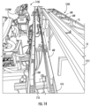
- the TNP staging area 1720 is an electromechanical assembly configured for receiving bundles, or stacks, of TNPs from the robot 1610 and distributing these TNP stacks to one of the TNP loaders 1730, from which the TNP stacks are loaded onto the TNP registration areas, generally designated 1740.
- the TNP registration areas comprise a bottom surface 1742 and two wall 1744, against which the TNP stacks are pressed (e.g., via linear actuators) to ensure that the TNP stacks are positionally registered in a known, or zero, position, for lifting by the robots 1710 onto the TNP delivery rail 1750, which moves the TNPs (e.g., individually) towards the conveyor 1551 at the TNP jig placement station 1800.
- the TNPs are plates that are formed in a unitary, or monolithic, manner and comprise a plurality of protrusion elements that extend away from a base plate structure, in the manner of a plurality of nails or other fasteners, and are configured for driving through one of the truss chords into one or more of the angled and/or upright webs on the assembly jig 10 for rigidly attaching together the truss chord and the angled and/or upright webs, through which such TNP is pressed (e.g., at the nail plate press station 1900).
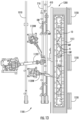
- the assembly jig 10 is transferred along a set of conveyors 1552 to the nail plate pressing station 1900, as shown in FIGS. 15 and 17 .
- the BNPs and the TNPs that are positioned about the truss chords are pressed (e.g., by press plates) into and through the truss chords and into the upright webs and/or the angled webs to rigidly interconnect the truss chords with the angled and upright webs to form a finished, or complete, truss element.
- the BNPs and the TNPs are advantageously pressed flush with (e.g., coplanar with) the outer surface of the truss chord through which the BNPs or the TNPs, respectively, are driven by the press plates.
- the assembly jig 10 with the finished truss element thereon is transported by the set of conveyors 1552 to the finished truss unloading station 2000, which comprises a conveyor 1553 and an automated robot 2010 configured to unload the finished truss element from the assembly jig 10 and to transfer the finished truss element to the finished truss storage station 2100.
- the robot 2010 can be of any suitable type for grasping and manipulating the finished truss element, but in the example embodiment discussed herein is a robotic arm with a grasping end effector (e.g., a grasping and/or suction mechanism) that is configured to detect a position of the finished truss element on the assembly jig 10, to lift the finished truss element off of the assembly jig 10, and to transfer the finished truss element to the finished truss storage station 2100.
- the truss storage station 2100 can, in some embodiments, be omitted entirely and/or modified into any suitable storage or staging area for finished truss elements after their assembly by the system 1.
- the finished truss storage station 2100 comprises a multi-level storage rack 2110, such that, for example, finished truss elements of different dimensions can be stored on different levels of the multi-level storage rack 2110.
- the multi-level storage rack 2110 has an induction level 2112, into which the finished truss elements are directly deposited by the robot 2010 of the finished truss unloading station 2000.
- the induction level 2112 comprises at least two independently operable conveyors, namely, an induction conveyor 2114 and a transport conveyor 2116.
- the robot 2010 places each of the finished truss elements sequentially onto the induction conveyor 2114, which moves the finished truss elements in a first direction and, optionally, positionally registers the finished truss elements against a stop plate on a distal side of the induction level 2112 in the first direction, such that each subsequently deposited finished truss element is abutted against a previously deposited finished truss element to form a laterally-extending "stack," or bundle, of finished truss elements within the induction level 2112.
- the rotating platforms e.g., belts, chains, rollers, etc.
- the rotating platforms that form the induction conveyor 2114 move vertically downward (e.g., to a position entirely below the plane defined by the rollers of the transport conveyor 2116), such that the stack of finished truss elements is directly resting on (e.g., only on) the rollers of the transport conveyor 2116, which is configured to move the stack of finished truss elements in a second direction, which is a different direction from (e.g., perpendicular to) the first direction, onto a truss elevator 2150.
- the rotating platforms e.g., belts, chains, rollers, etc.
- the rotating platforms that form the induction conveyor move vertically upward (e.g., to a position in which the upper surface of the rotating platforms of the induction conveyor 2114 are above the plane defined by the rollers of the transport conveyor 2116) to receive further finished truss elements from the robot 2010 at the finished truss unloading station 2000.
- the truss elevator 2150 raises the stack of finished truss elements, based on the physical characteristics of the finished truss elements produced by the system 1, to a designated level within the multi-level storage rack 2110 for the storage of the stack of finished truss elements until it is requested for such stack of truss elements to be retrieved from the multi-level storage rack 2110.
- the truss elevator 2150 comprises a plurality of rollers that are configured to move the stack of finished truss elements in the second direction (e.g., forward and backward in the second direction) for loading the stack of finished truss elements onto one of the levels of the multi-level storage rack 2110 for storage or off of one of the levels of the multi-level storage rack 2110 for retrieval.
- the truss elevator 2150 is also configured to move vertically between the various levels of the multi-level storage rack 2110.
- the truss elevator 2150 upon receipt of a command from a controller, retrieves a stack of truss elements from a designated level of the multi-level storage rack 2110, on which the stack of finished truss elements is indicated (e.g., in a database) as being stored.
- the truss elevator 2150 then is configured to lower the designated stack of finished truss elements from the level on the multi-level storage rack 2110 where it was stored to a transport level (e.g., coplanar with the induction level 2112) and then is configured to transport (e.g., using a plurality of rollers, which may be any combination of drive and idler rollers, including exclusively driven rollers) the stack of finished truss elements to another system for use in construction of, for example, modular building units.
- a transport level e.g., coplanar with the induction level 2112
- transport e.g., coplanar with the induction level 2112
- transport e.g., using a plurality of rollers, which may be any combination of drive and idler rollers, including exclusively driven rollers
- the truss elevator 2150 and the multi-level storage rack 2110 of the finished truss storage station 2100 provide a storage area for the finished truss elements that are not designated for immediate use in another system (e.g., an automated construction system).
- the assembly jig 10 is then transported, via the set of conveyors 1550, to the finished lumber jig placement station 1200, where the angled webs, upright webs, and truss chords are positioned on the assembly jig 10.
- the assembly jig 10 is transported along the conveyor 1551 to the TNP jig placement station 1800, where the assembly jig 10 receives TNPs in the designated positions for the truss element being assembled.
- the assembly jig 10 is then transported, via the set of conveyors 1552, to the nail plate press station 1900, where the BNPs and the TNPs are pressed through the truss chords and into various of the angled webs and/or upright webs, for rigidly interlocking the angled webs, the upright webs, and the truss chords together, thereby producing a finished truss element.
- the set of conveyors 1552 continue to transport the assembly jig 10, with the finished truss element still supported thereon, onto the conveyor 1553 at the finished truss unloading station 2000, where the robot 2010 unloads the finished truss element from the assembly jig 10 for use or storage (e.g., at the finished truss storage station 2100.
- the conveyor 1553 transports the empty assembly jig 10 back to the BNP jig placement station 1500, where the truss element assembly process starts again by the placement of the BNPs onto the assembly jig in the designated positions for the truss element being assembled. This counterclockwise movement of the assembly jigs 10 is repeated until a desired quantity of finished truss elements has been assembled.
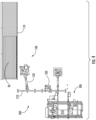
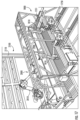
- FIG. 21 An alternate embodiment for a truss lumber placement station, designated 2200, is schematically illustrated by the region outlined in broken lines, as shown in FIG. 21 , with various aspects of the truss lumber placement station 2200 being shown in FIGS. 22-24 .
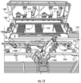
- the truss lumber placement station 2200 extends over the conveyors 1550 and also over the region in which the truss lumber placement station 1200 is located, as shown in FIG. 10 .
- This region in which the truss lumber placement station is located in the embodiment shown in FIG. 10 is, as shown in FIGS. 22 and 24 , utilized as a staging area, generally designated 1201. As shown in FIGS.
- the truss lumber placement station 2200 comprises a frame 1210 that is positioned around and, at least in part, vertically above the staging area 1201 and at least a portion of each of the conveyors 1550.
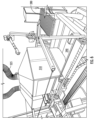
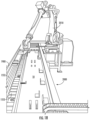
- An automated robot 2300 is attached (e.g., rigidly, or fixedly) to an upper portion of the frame 2210 that is, as shown, vertically above (e.g., directly over) the conveyors 1550.
- An assembly shelf 2220 is attached (e.g., rigidly, or fixedly) to a lower portion of the frame 2210 that is, as shown, vertically above (e.g., directly over) the staging space 1201.
- the assembly jig 10 When the assembly jig 10 is held within the staging area 1201, the assembly jig 10 is on the conveyor 1551, which will transport the assembly jig 10 to the TNP jig placement station 1800 upon receipt of a signal (e.g., from a controller). Thus, at least a portion of the conveyor 1551 is positioned within the staging area 1201.
- these finished pieces of lumber are optimally slid against a surface (e.g., of the assembly jig 10) against other adjacent pieces of the truss lumber to account for dimensional variances of the lumber.
- the finished truss lumber pieces are placed (e.g., in a vertical direction) directly onto the assembly jig 10 without any lateral (e.g., sliding) movement, which can result in finished truss elements that, while structurally sound, can have gaps between adjacent pieces of lumber in the finished truss element.
- the finished pieces of truss lumber are positioned on the assembly shelf 2220 and transferred (e.g., in unison) by the robot 2300 onto the assembly jig 10 at the same time.
- the assembly shelf 2220 is positioned vertically above a portion of the conveyor 1551, such that a space, referred to herein as the staging area 2201, is defined between the conveyor 2201 and the assembly shelf 2220.
- the robot 2300 can grasp and transfer all of the angled webs, upright webs, and truss chords at the same time and transfer them onto (e.g., vertically) the assembly jig 10 and, necessarily, directly onto the BNPs already on the assembly jig 10, while the assembly jig 10 is on the conveyors 1550.
- the assembly shelf 2220 further comprises, attached to the base 2222 and/or the frame 2210, clamping/squaring devices, generally designated 2230.
- the cleat 2232 is extended until one edge of the unassembled truss element defined by the finished pieces of truss lumber in the assembled configuration is pressed (e.g., directly) against the wall 2226 and the other edge of the unassembled truss element is pressed (e.g., directly) against the cleats 2232.
- the unassembled truss element is compressed between the cleats 2232 and the wall 2226 by the extension of the cleats 2232 caused by the activation of the actuators 2234.
- the finished pieces of truss lumber in the unassembled truss element are held (e.g., frictionally) by the actuators attached to the frame 2350 in the configuration for the truss element being assembled before the finished pieces of truss lumber in the unassembled truss element are lifted off of the assembly shelf 2220, while the finished pieces of truss lumber in the unassembled truss element are lifted off of the assembly shelf 2220, while the finished pieces of truss lumber in the unassembled truss element are moved between the assembly shelf 2220 and the assembly jig 10 on the conveyors 1550, and while the finished pieces of truss lumber in the unassembled truss element are deposited vertically onto the assembly jig 10 on the conveyors 10.
- the finished pieces of truss lumber in the unassembled truss element are deposited (e.g., directly) onto the BNPs already loaded onto the assembly jig 10 at the BNP jig placement station 1500 and the actuators of the frame 2300 are retracted, such that the finished pieces of truss lumber in the unassembled truss element are no longer compressed against each other.
- the finished pieces of truss lumber in the unassembled truss element are positioned precisely onto the assembly jig 10 by the robot 2300 and the assembly jig 10 is then moved into the staging area 1201 underneath the assembly shelf 2220.
- the assembly jig is transported to the TNP jig placement station 1500 and assembly of the truss element proceeds as described elsewhere herein (e.g., TNPs are positioned onto the finished pieces of truss lumber in the unassembled truss element at the TNP jig placement station 1800, the BNPs and TNPs are driven into the finished pieces of truss lumber in the unassembled truss element within the nail plate press station 1900, and the finished truss element is unloaded from the assembly jig 10 at the finished truss unloading station 2000.
- TNPs are positioned onto the finished pieces of truss lumber in the unassembled truss element at the TNP jig placement station 1800
- the BNPs and TNPs are driven into the finished pieces of truss lumber in the unassembled truss element within the nail plate press station 1900
- the finished truss element is unloaded from the assembly jig 10 at the finished truss un
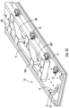
- FIG. 25 is a partial view of an example embodiment of an assembly jig 10 suitable for use with the system 1 in producing truss elements.
- a finished truss element is shown positioned on the assembly jig 10.
- the assembly jig 10 comprises a plate 12, on which the finished pieces of truss lumber are arranged, and by which the finished pieces of truss lumber are supported.
- An alignment block 20 is rigidly attached to the plate 12 and/or the walls 14 and has an alignment hole 22 formed through the entire thickness of the alignment block 20 (e.g., in the direction perpendicular to the plane defined by the plate 12).
- the plate 12 has an opening (e.g., a hole that is the same size or larger than the alignment hole 22) formed therein and aligned with the alignment hole 22 so that an alignment pin (e.g., 2420, FIG. 26 ) can be inserted through the alignment hole 22 from the direction of the plate 12, relative to the alignment block 20.
- an alignment pin e.g., 2420, FIG. 26
- the BNPs are positioned directly against the plate 12, the angled webs AW, the upright webs UW, and the truss chords TC are spaced apart from the plate 12 by the BNPs and the TNPs are positioned on the opposite side of the angled webs AW, the upright webs UW, and the truss chords TC from the side on which the BNPs are arranged.
- the assembly jig 10 comprises stops 16 and clamps 18, which compress the finished pieces of truss lumber in the unassembled truss element between the clamps 18 and the stops 16.
- the clamps 18 and/or the stops 16 can be omitted from the assembly jig 10.
- the clamps 18 can be actuated, for example, pneumatically or hydraulically.
- the clamps 18 are actuated after the finished pieces of truss lumber in the unassembled truss element are deposited onto the assembly jig 10 by the robot 2300 on the conveyors 1550 and, advantageously, remain actuated until the finished truss element is formed at the nail plate press station 1900, after which the clamps 18 are retracted to allow for removal of the finished truss element from the assembly jig 10 at the finished truss unloading station 2000.
- one or more tapered alignment pins may be utilized at each such station for insertion into one or more corresponding locating holes that are formed in the assembly jig 10.
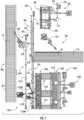
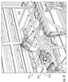
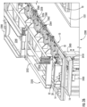
- FIG. 26 shows such engagement of one of the alignment pins 2420 within an alignment hole 22 at the truss wood placement station 2200.
- the tapered pins 2420 are axially extended (e.g., in the vertical direction of FIG.
- the alignment pins 2420 are retracted so that the assembly jig 10 can be moved by the conveyors 1550 onto the conveyor 1551 in the staging area 2201.
- the robot 2300 is shown using the truss-lifting end-effector 2350 to place the unassembled truss elements onto the assembly jig 10 at the truss wood placement station 2200.
- the conveyors 1550 are not shown to illustrate other features of the truss wood placement station 2200 with greater clarity.
- a stop plate 2400 is provided, which is operably attached to an actuator 2410 (e.g., a linear actuator) that is configured to move the stop plate 2400 vertically between an extended position and a retracted position.
- an actuator 2410 e.g., a linear actuator
- the stop plate 2400 In the extended position, the stop plate 2400 extends above the uppermost plane of the transport surface (e.g., of the rollers, a belt, etc.) of the conveyors 1550 to contact (e.g., directly) the assembly jig 10 and prevent a movement of the assembly jig 10 beyond the stop plate 2400. In the retracted position, the stop plate 2400 is retracted beneath the uppermost plane of the transport surface (e.g., of the rollers, a belt, etc.) of the conveyors 1550, such that the assembly jig 10 can move along the conveyors 10 past the stop plate 2400 without making contact with the stop plate 2400.
- the transport surface e.g., of the rollers, a belt, etc.
- At least two stop plates 2400 are provided at the truss wood placement station 2200 and are spaced out (e.g., adjacent to different conveyors 1550) such that multiple points on the assembly jig 10 are contacted by the stop plates 2400.
- the movement of each of the alignment pins 2420 in the vertical direction is controlled via an actuator to which the alignment pin is rigidly attached, as shown in FIG. 26 .
- the truss-lifting end-effector 2350 is connected to the robot 2300 via a bracket 2340.
- the attachment of the truss-lifting end-effector 2350 to the bracket 2340 is accomplished via a spring-biased sliding rod engagement, such that damping in the direction of compression of the unassembled truss element is provided between the bracket 2340 and the truss-lifting end-effector 2350, which advantageously maintains a more consistent compression force on the unassembled truss element by the truss-lifting end-effector 2350.
- a different type of attachment between the bracket 2340 and the truss-lifting end-effector 2350 can be provided.
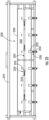
- the truss-lifting end-effector 2350 comprises a frame 2352, to which the bracket 2340 is connected.
- the frame comprises vertically-extending walls 2354 and brackets 2356.
- the brackets 2356 have attached thereto an actuator 2358 (e.g., a linear actuator) which is extendable in a direction towards the vertically-extending walls 2354.
- the vertically-extending walls 2354 are aligned with the brackets 2356.
- the quantity of brackets 2356 and the quantity of the vertically-extending walls 2354 are the same.
- the quantity of brackets 2356 and the quantity of the vertically-extending walls 2354 are different.
- Each actuator 2358 is connected at a distal end to at least one slider 2360, which is movable along a rod rigidly attached to the frame. It is advantageous, in order to ensure proper alignment and avoid inducing moments of rotation, for each actuator 2358 to be attached to two sliders 2360, which are positioned, respectively, on opposite sides of the actuator 2358.
- the sliders 2360 are connected (e.g., rigidly and/or directly) to a plate 2362, which extends in a plane that is substantially parallel to the plane defined by the frame 2353 of the truss-lifting end-effector 2350.
- the rods 2350 extend in the same direction as the direction of extension of the actuator 2358, such that the plate 2362 is also movable in the same direction as the direction of extension of the actuator 2358 to which the plate 2362 is attached.
- a push bar 2364 that is attached (e.g., rigidly, as a monolithic structure) at the distal end (e.g., the end closest to the vertically-extending walls 2354 on the opposite side of the frame 2352) of the plate 2362.
- the push bar 2364 comprises a substantially planar surface, which is the surface that directly contacts the unassembled truss element during movement between the assembly shelf 2220 and the assembly jig 10 via the truss-lifting end-effector 2350.
- the push bars 2364 each extend in a substantially vertical direction to engage against one of the truss chords of the unassembled truss element during movement between the assembly shelf 2220 and the assembly jig 10.
- the sliders 2360 move along the rods and, necessarily, the plates 2362 and the push bars 2364 move simultaneously (e.g., in unison) in the direction towards the vertically-extending walls 2354 to compress the unassembled truss element between the vertically-extending walls and the push bars 2364 for transfer in unison of all of the angled webs, upright webs, and truss chords that form the unassembled truss element from the assembly shelf 2220 to the assembly jig 10 at the truss wood placement station 2200 (e.g., on the conveyors 1550).
- each actuator 2358 Via retraction of each actuator 2358 (e.g., in the direction opposite the extension direction of such actuator 2358), the sliders 2360 move along the rods and, necessarily, the plates 2362 and the push bars 2364 move simultaneously (e.g., in unison) in the direction away from the vertically-extending walls 2354 to release the unassembled truss element onto the assembly jig 10 (e.g., directly onto the BNPs already in position on the assembly jig 10).
- the actuators 2358 are retracted only when the unassembled truss element is in contact with the assembly jig 10 (e.g., with only the BNPs positioned between the assembly jig 10 and the unassembled truss element), such that assembly jig 10 can be moved via the conveyors 1550 into the staging area 2201 and another assembly jig 10 can be transferred from the BNP jig placement station 1500 into the position shown in FIGS.
- the operations at each of the truss wood placement station 1200, 2200, the BNP placement station 1500, the TNP placement station 1800, the nail plate press station 1900, and/or the finished truss unloading station 2000 are performed simultaneous on a plurality of assembly jigs 10, each such station having a different assembly jig 10 positioned there.
- the vertically-extending walls 2354 extend beneath the frame 2352 and, advantageously, at least to within a same horizontal plane as a portion of the push bars 2364. In some embodiments, the vertically-extending walls 2354 extend at least in a vertical direction to or below a horizontal plane defined by a bottom surface of the push bars 2364. In some embodiments, the bottom surface of each of the vertically-extending walls 2354 is substantially coplanar with the bottom surface of each of the push bars 2364.
Landscapes
- Engineering & Computer Science (AREA)
- Life Sciences & Earth Sciences (AREA)
- Wood Science & Technology (AREA)
- Forests & Forestry (AREA)
- Architecture (AREA)
- Mechanical Engineering (AREA)
- Manufacturing & Machinery (AREA)
- Civil Engineering (AREA)
- Structural Engineering (AREA)
- Conveying And Assembling Of Building Elements In Situ (AREA)
- Rod-Shaped Construction Members (AREA)
Claims (15)
- Automatisiertes System (1) zur Herstellung von Fachwerkelementen zur Verwendung in modularen Baueinheiten, wobei das System (1) umfasst:eine Gruppierung von Stationen mit abgewinkelten Stegen (100, 200, 300, 400), die so konfiguriert sind, dass sie Dimensionsholz aufnehmen und schneiden, um abgewinkelte Stege zur Verwendung bei der Montage der Fachwerkelemente zu bilden;dadurch gekennzeichnet, dass das automatisierte System:eine Gruppierung von Stationen mit aufrechten Stegen (500, 600, 700) umfasst, die so konfiguriert sind, dass sie Dimensionsholz aufnehmen und schneiden, um aufrechte Stege zur Verwendung bei der Montage der Fachwerkelemente zu bilden;eine Fachwerkgurt-Gruppierung von Stationen (800, 900, 1000), die so konfiguriert sind, dass sie Dimensionsholz aufnehmen und zuschneiden, um Fachwerkgurte zur Verwendung bei der Montage der Fachwerkelemente zu bilden;eine Station zum Zusammenführen/Übertragen von Fertigholz (1100), die so konfiguriert ist, dass sie:die abgewinkelten Stege von der Gruppierung von Stationen mit abgewinkelten Stegen (100, 200, 300, 400) aufnehmen die aufrechten Stege aus der Gruppierung von Stationen mit aufrechten Stegen (500, 600, 700) und die Fachwerkgurte aus der Fachwerkgurt-Gruppierung von Stationen (800, 900, 1000); unddie abgewinkelten Stege, die aufrechten Stege und die Fachwerkgurte übertragen auf eine Montagevorrichtung (10) an einer Platzierungsstation der Montagevorrichtung für Fertigholz (1200);eine Gruppierung von Stationen mit unteren Nagelplatten, BNP (1300, 1400, 1500), die so konfiguriert ist, dass sie BNPs auf der Montagevorrichtung (10) in bestimmten Positionen für die herzustellenden Fachwerkelemente aufnimmt und positioniert;eine Gruppierung von Stationen mit oberen Nagelplatten, TNP (1600, 1700, 1800), die so konfiguriert ist, dass sie TNPs auf der Montagevorrichtung (10) in bestimmten Positionen für die herzustellenden Fachwerkelemente aufnimmt und positioniert; undeine Nagelplatten-Pressstation (1900), die so konfiguriert ist, dass sie die BNPs und die TNPs durch einen entsprechenden der Fachwerkgurte und in einen oder mehrere der abgewinkelten Stege und/oder aufrechten Stege presst, um die abgewinkelten Stege, die aufrechten Stege und die Fachwerkgurte starr miteinander zu verriegeln, um ein fertiges Fachwerkelement zu bilden;wobei die Montagevorrichtung (10) Ausrichtungs- und/oder Positionierungsmerkmale aufweist die so konfiguriert sind, dass sie die TNPs, die BNPs, die Fachwerkgurte, die aufrechten Stege und die abgewinkelten Stege in Ausrichtung zueinander halten, um eines der Fachwerkelemente zu bilden.
- System (1) nach Anspruch 1, umfassend:eine Lagerstation für fertige Fachwerke (2100), die so konfiguriert ist, dass sie fertige Fachwerkelemente lagert; undeine Entladestation für fertige Fachwerke (2000), die so konfiguriert ist, dass sie fertige Fachwerkelemente von der Montagevorrichtung (10) zur Lagerstation für fertige Fachwerke (2100) transportiert; undoptional, wobei:die Lagerstation für fertige Fachwerke (2100) ein mehrstöckiges Lagerregal (2110), das mindestens eine Induktionsebene und eine oder mehrere obere Ebenen hat, und einen Fachwerkaufzug (2150) umfasst,die Induktionsebene umfassend einen Induktionsförderer (2114), der so konfiguriert ist, dass er die fertigen Fachwerkelemente zu einem Stapel von fertigen Fachwerkelementen bildet, und einen Transportförderer (2116), der so konfiguriert ist, dass er den Stapel von fertigen Fachwerkelementen auf den Fachwerkaufzug (2150) übergibt;der Induktionsförderer (2114) vertikal zwischen einer Induktionsposition, in der eine Ebene, auf der die fertigen Fachwerkelemente von dem Induktionsförderer (2114) getragen werden, über einer Ebene liegt, die durch eine obere Fläche des Transportförderers (2116) definiert ist, und einer Transportposition, in der die Ebene, auf der die Fachwerkelemente von dem Induktionsförderer (2114) getragen werden, unter der Ebene liegt, die durch die obere Fläche des Transportförderers (2116) definiert ist, bewegbar ist, undder Fachwerkaufzug (2150) so konfiguriert ist, dass er den Stapel fertiger Fachwerkelemente zwischen der Induktionsebene und einer beliebigen der einen oder mehreren oberen Ebenen vertikal bewegt; undferner optional, wobei die Entladestation für fertige Fachwerke (2000) einen automatisierten Roboter umfasst, der so konfiguriert ist, dass er das fertige Fachwerkelement von der Montagevorrichtung (10) abhebt und das fertige Fachwerkelement auf dem Induktionsförderer (2114) des mehrstufigen Lagerregals (2110) ablegt.
- System (1) nach Anspruch 1, wobei die Gruppierung von Stationen mit abgewinkelten Stegen (100, 200, 300, 400) eine Ladestation für abgewinkelte Stegen (100), eine Station für den Grobschnitt von abgewinkelten Stegen (200), eine Station Station für den Fertigschneiden von abgewinkelten Stegen (300) und eine Abgabe Station für abgewinkelte Stege (400) umfasst, undoptional, wobei die Ladestation für abgewinkelte Stegen (100) umfasst:einen Förderer (110), der so konfiguriert ist, dass er das Dimensionsholz zur Verwendung bei der Bildung von abgewinkelten Stegen bereitstellt; undeinen automatisierten Roboter (120), der so konfiguriert ist, dass er das Dimensionsholz zur Station für den Grobschnitt von abgewinkelten Stegen (200) transportiert; undferner optional, wobei die Station für den Grobschnitt von abgewinkelten Stegen (200) umfasst:eine Säge (220) zum Schneiden des Dimensionsholzes in abgewinkelte Stegsegmente, undeine Zuführrinne (210), die so konfiguriert ist, dass sie das Dimensionsholz vom Roboter der Ladestation für abgewinkelte Stegen (100) aufnimmt und das Dimensionsholz relativ zur Säge bewegt;das System (1) umfassend:
eine Steuerung, die so konfiguriert ist, dass sie eine Bewegung des Dimensionsholzes entlang der Zuführrinne (210) und eine Betätigung der Säge steuert, um die abgewinkelten Stegsegmente mit einer Länge zu erzeugen, die in Anweisungen spezifiziert ist, die in einer Datenbank gespeichert sind, die mit der Steuerung für die herzustellenden Fachwerkelemente verbunden ist, undferner optional, wobei die Station für den Fertigschneiden von abgewinkelten Stegen (300) umfasst:eine Schneidemaschine zum Formen eines Endprofils an gegenüberliegenden Enden jedes der abgewinkelten Stegsegmente, um einen fertige abgewinkelte Steg zu erzeugen, undeinen Förderer, der so konfiguriert ist, dass er das abgewinkelte Stegsegment in die Schneidemaschine transportiert und der fertige abgewinkelte Steg zu einer Förderrinne der Abgabestation für abgewinkelte Stege (400) transportiert; undferner optional, wobei die Förderrinne der Abgabestation für abgewinkelte Stege (400) so konfiguriert ist, dass sie die fertigen abgewinkelte(n) Stege zur Station zum Zusammenführen/Übertragen von Fertigholz (1100) transportiert. - System (1) nach Anspruch 1, wobei die Gruppierung von Stationen mit aufrechten Stegen (500, 600, 700) eine Ladestation für aufrechte Stege (500), eine Schneidestation für aufrechte Stege (600) und eine Abgabestation für aufrechte Stege (700) umfasst, undoptional, wobei die Ladestation für aufrechte Stege (500) umfasst:einen Förderer (510), der so konfiguriert ist, dass er das Dimensionsholz zur Verwendung bei der Bildung der aufrechten Stege bereitstellt; undeinen automatisierten Roboter (520), der so konfiguriert ist, dass er das Dimensionsholz zur Schneidestation für aufrechte Stege (600) überträgt; undferner optional, wobei die Schneidestation für aufrechte Stege (600) umfasst:eine Säge (620) zum Schneiden des Dimensionsholzes in fertige, aufrechte Stege, undeine Zuführrinne (610), die so konfiguriert ist, dass sie das Dimensionsholz vom Roboter der Ladestation für aufrechte Stege (500) aufnimmt und das Dimensionsholz relativ zur Säge bewegt;das System (1) umfassend:eine Steuerung, die so konfiguriert ist, dass sie eine Bewegung des Dimensionsholzes entlang der Zuführrinne und eine Betätigung der Säge steuert, um die fertigen aufrechten Stege mit einer Länge zu erzeugen, die in Anweisungen spezifiziert ist, die in einer Datenbank gespeichert sind, die mit der Steuerung für die herzustellenden Fachwerkelemente verbunden ist,wobei die fertigen aufrechten Stege nach dem Schneiden des Dimensionsholzes durch die Säge zu einer Förderrinne (710) der Abgabestation für aufrechte Stege (700) übergeben werden, undferner optional, wobei die Förderrinne der Abgabestation für aufrechte Stege (700) so konfiguriert ist, dass sie die fertigen aufrechten Stege zur Station zum Zusammenführen/Übertragen von Fertigholz (1100) transportiert.
- System (1) nach Anspruch 1, wobei die Fachwerkgurt-Gruppierung von Stationen (800, 900, 1000) eine Ladestation für Fachwerkgurte (800), eine Schneidestation für Fachwerkgurte (900) und eine Abgabestation für Fachwerkgurte (1000) umfasst; undoptional, wobei die Ladestation für Fachwerkgurte (800) umfasst:einen Förderer (810), der so konfiguriert ist, dass er das Dimensionsholz zur Verwendung bei der Bildung der Fachwerkgurte bereitstellt; undeinen automatisierten Roboter (820), der so konfiguriert ist, dass er das Dimensionsholz zur Schneidestation für Fachwerkgurte (900) transportiert; undferner optional, wobei die Schneidestation für Fachwerkgurte (900) umfasst:eine Säge (920) zum Schneiden des Dimensionsholzes in fertige Fachwerkgurte; undeine Zuführrinne (910), der so konfiguriert ist, dass er das Dimensionsholz vom Roboter der Ladestation für Fachwerkgurte (800) aufnimmt und das Dimensionsholz relativ zur Säge bewegt;das System (1) umfassend:eine Steuerung, die so konfiguriert ist, dass sie eine Bewegung des Dimensionsholzes entlang der Zuführrinne und eine Betätigung der Säge steuert, um die fertigen Fachwerkgurte mit einer Länge zu erzeugen, die in Anweisungen spezifiziert ist, die in einer Datenbank gespeichert sind, die mit der Steuerung für die herzustellenden Fachwerkelemente verbunden ist;wobei die fertige Fachwerkgurte nach dem Schneiden des Dimensionsholzes durch die Säge zu einer Förderrinne (1010) der Abgabestation für Fachwerkgurte (1000) transportiert werden; undferner optional, wobei die Förderrinne der Abgabestation für Fachwerkgurte (1000) so konfiguriert ist, dass sie die fertigen Fachwerkgurte zur Station zum Zusammenführen/Übertragen von Fertigholz (1100) transportiert.
- System (1) nach Anspruch 1, wobei die Station zum Zusammenführen/ Übertragen von Fertigholz (1100) mindestens einen Roboter umfasst, der so konfiguriert ist, dass er fertige Abgewinkelten Stege, fertige aufrechte Stege und fertige Fachwerkgurte gemäß den in einer Datenbank für die herzustellenden Fachwerkelemente gespeicherten Anweisungen auf die Montagevorrichtung (10) an der Platzierungsstation der Montagevorrichtung für Fertigholz (1200) überträgt.
- System (1) nach Anspruch 6, wobei die BNP-Gruppierung von Stationen (1300, 1400, 1500) so konfiguriert ist, dass sie BNPs an vorgeschriebenen Stellen auf der Montagevorrichtung (10) gemäß den Anweisungen für die herzustellenden Fachwerkelemente platziert, bevor die fertigen Abgewinkelten Stege, die fertigen aufrechten Stege und die fertigen Fachwerkgurte auf die Montagevorrichtung (10) an der Platzierungsstation der Montagevorrichtung für Fertigholz (1200) übertragen werden.
- System (1) nach Anspruch 6, das einen Förderer umfasst, der so konfiguriert ist, dass er die Montagevorrichtung (10) von der Platzierungsstation der Montagevorrichtung für Fertigholz (1200) zu einer TNP-Vorrichtungsplatzierungsstation (1800) der TNP-Gruppierung von Stationen (1600, 1700, 1800) bewegt, die so konfiguriert ist, dass sie TNPs an vorgeschriebenen Stellen auf der Montagevorrichtung (10) gemäß den Anweisungen für die herzustellenden Fachwerkelemente platziert; undoptional mit einem oder mehreren Förderern, die so konfiguriert sind, dass sie die Montagevorrichtung (10) von der TNP-Vorrichtungsplatzierungsstation (1800) zur Nagelplattenpressstation und, nachdem die Nagelplattenpressstation das fertige Fachwerkelement gebildet hat, von der Nagelplattenpressstation zur Entladestation (2000) für die fertigen Fachwerke bewegen; undferner optional einen weiteren Förderer umfassend, der so konfiguriert ist, dass er die Montagevorrichtung (10) von der Entladestation für fertige Fachwerke (2000) für zu einer BNP-Vorrichtungsplatzierungsstation (1500) der BNP-Gruppierung von Stationen (1300, 1400, 1500) bewegt, die so konfiguriert ist, dass sie BNPs an vorgeschriebenen Stellen auf der Montagevorrichtung (10) gemäß den Anweisungen zur Herstellung eines anderen der Fachwerkelemente platziert.
- System (1) nach Anspruch 1, wobei das System (1) so konfiguriert ist, dass Fachwerkelementen gleichzeitig auf einer Vielzahl von Montagevorrichtungen (10) montiert werden können.
- Verfahren zur automatisierten Herstellung von Fachwerkelementen zur Verwendung in modularen Baueinheiten, wobei das Verfahren umfasst:Aufnehmen und Schneiden von Dimensionsholz an einer Gruppierung von Stationen mit abgewinkelten Stegen (100, 200, 300, 400), um abgewinkelte Stege zur Verwendung bei der Montage der Fachwerkelemente zu bilden;dadurch gekennzeichnet, dass das Verfahren ferner umfasst:Aufnehmen und Schneiden in einer Gruppierung von Stationen mit aufrechten Stegen (500, 600, 700), Dimensionsholz zu aufrechten Stegen für Verwendung bei der Montage der Fachwerkelemente;Aufnehmen und Schneiden, an einer Fachwerkgurt-Gruppierung von Stationen (800, 900, 1000), Dimensionsholz zur Bildung von Fachwerkgurte für Verwendung bei der Montage der Fachwerkelemente;Aufnehmen der abgewinkelten Stege aus der Gruppierung von Stationen mit abgewinkelten Stegen (100, 200, 300, 400), der aufrechten Stege aus der Gruppierung von Stationen mit aufrechten Stegen (500, 600, 700) und der Fachwerkgurte aus der Fachwerkgurt-Gruppierung von Stationen (800, 900, 1000) an einer Station zum Zusammenführen/Übertragen von Fertigholz (1100);Übergabe der abgewinkelten Stege, der aufrechten Stege und der Fachwerkgurte an der Station zum Zusammenführen/Übertragen von Fertigholz (1100) auf einer eine Montagevorrichtung (10) an einer Platzierungsstation der Montagevorrichtung für Fertigholz (1200);Aufnahme und Positionierung, an einer Gruppierung von Stationen für unteren Nagelplatten, BNP (1300, 1400, 1500), BNPs auf der Montagevorrichtung (10) in bestimmten Positionen für die herzustellenden Fachwerkelemente;Aufnahme und Positionierung an einer Gruppierung von Stationen für oberen Nagelplatten, TNP (1600, 1700, 100), TNPs auf der Montagevorrichtung (10) in bestimmten Positionen für die herzustellenden Fachwerkelemente;Pressen der BNPs und der TNPs in einer Nagelplattenpressstation (1900) durch einen entsprechenden der Fachwerkgurte und in einen oder mehrere der abgewinkelten Stege und/oder aufrechten Stege, um die abgewinkelten Stege, die aufrechten Stege und die Fachwerkgurte starr miteinander zu verriegeln um ein fertiges Fachwerkelement zu bilden;wobei die Montagevorrichtung (10) Ausrichtungs- und/oder Positionierungsmerkmale aufweist die so konfiguriert sind, dass sie die TNPs, die BNPs, die Fachwerkgurte, die aufrechten Stege und die abgewinkelten Stege in Ausrichtung zueinander halten, um eines der Fachwerkelemente zu bilden.
- Verfahren nach Anspruch 10, umfassend:Lagerung von fertigen Fachwerkelementen in einer Lagerstation für fertige Fachwerke (2100); undÜbergabe an einer Entladestation für fertige Fachwerke (2000) von fertigen Fachwerkelementen von der Montagevorrichtung (10) zur Lagerstation für fertige Fachwerke (2100); undoptional, wobei die Lagerstation für fertige Fachwerke (2100) ein mehrstöckiges Lagerregal (2110), das mindestens eine Induktionsebene und eine oder mehrere obere Ebenen aufweist, und einen Fachwerkaufzug (2150) umfasst, wobei das Verfahren umfasst:Bilden der fertigen Fachwerkelemente mittels eines Induktionsförderers (2114) der Induktionsebene zu einem Stapel fertiger Fachwerkelemente;Übergabe des Stapels fertiger Fachwerkelemente mittels eines Transportförderers (2116) der Induktionsebene auf den Fachwerkaufzug (2150);Bewegen des Induktionsförderers (2114) in vertikaler Richtung zwischen einer Induktionsposition, in der eine Ebene, auf der die fertigen Fachwerkelemente von dem Induktionsförderer (2114) getragen werden, über einer Ebene liegt, die durch eine obere Fläche des Transportförderers (2116) definiert ist, und einer Transportposition, in der die Ebene, auf der die Fachwerkelemente von dem Induktionsförderer (2114) getragen werden, unter der Ebene liegt, die durch die obere Fläche des Transportförderers (2116) definiert ist; undBewegen des Stapels fertiger Fachwerkelementen mittels des Fachwerkaufzugs (2150) in vertikaler Richtung zwischen der Induktionsebene und einer der einen oder mehreren oberen Ebenen; undferner optional, wobei die Entladestation (2000) für fertige Fachwerke eine automatisierten Roboter umfasst, wobei das Verfahren umfasst:Abheben des fertigen Fachwerkelements von der Montagevorrichtung (10) mittels des automatisierten Roboters; undAblegen des fertigen Fachwerkelements mittels des automatisierten Roboters auf den Induktionsförderer (2114) des mehrstöckigen Lagerregals (2110).
- Verfahren nach Anspruch 10, wobei die Gruppierung von Stationen mit abgewinkelten Stegen (100, 200, 300, 400) eine Ladestation für abgewinkelte Stegen (100), eine Station für den Grobschnitt von abgewinkelten Stegen (200), eine Station Station für den Fertigschneiden von abgewinkelten Stegen (300) und eine Abgabe Station für abgewinkelte Stege (400) umfasst; undoptional, wobei die Ladestation für abgewinkelte Stegen (100) einen Förderer (110) und einen automatisierten Roboter (120) umfasst, wobei das Verfahren umfasst:Bereitstellen des Dimensionsholzes über den Förderer (110) zur Verwendung bei der Bildung der abgewinkelten Stege; undÜbergabe des Dimensionsholzes mittels des automatisierten Roboters (120) zur Station für den Grobschnitt von abgewinkelten Stegen (200); undferner optional, wobei die Station für den Grobschnitt von abgewinkelten Stegen (200) eine Säge (220) und eine Zuführrinne (210) umfasst, wobei das Verfahren umfasst:Aufnahme der Dimensionsholz vom Roboter (120) der Ladestation für abgewinkelte Stegen (100) in der Zuführrinne (210);Bewegung des Dimensionsholzes über die Zuführrinne (210) relativ zur Säge (220);Schneiden des Dimensionsholzes mit der Säge (220) in abgewinkelte Stegsegmente; undSteuern einer Bewegung des Dimensionsholzes entlang der Zuführrinne und einer Betätigung der Säge über eine Steuerung, um die abgewinkelten Stegsegmente mit einer Länge zu erzeugen, die in Anweisungen spezifiziert ist, die in einer Datenbank gespeichert sind, die mit der Steuerung für die herzustellenden Fachwerkelemente verbunden ist; undferner optional, wobei die Station für den Fertigschneiden von abgewinkelten Stegen (300) eine Schneidemaschine und einen Förderer, wobei das Verfahren umfasst:Ausbilden eines Endprofils durch die Schneidemaschine an gegenüberliegenden Enden jedes der abgewinkelten Stegsegmente, um eine fertige abgewinkelte Steg zu erzeugen;Transportieren des abgewinkelten Stegsegments über den Förderer in die Schneidemaschine; undTransportieren des fertigen abgewinkelten Stegs über den Förderer zu einer Förderrinne der Abgabestation für abgewinkelte Stege (400); undferner optional umfassend das Transportieren der fertigen abgewinkelten Stegen über die Förderrinne der Abgabestation für abgewinkelte Stege (400) zur Station zum Zusammenführen/Übertragen von Fertigholz (1100).
- Verfahren nach Anspruch 10, wobei die Gruppierung von Stationen mit aufrechten Stegen (500, 600, 700) eine Ladestation für aufrechte Stege (500), eine Schneidestation für aufrechte Stege (600) und eine Abgabestation für aufrechte Stege (700) umfasst; undoptional, wobei die Ladestation für aufrechte Stege (500) einen Förderer (510) und einen automatisierten Roboter (520) umfasst, wobei das Verfahren umfasst:Bereitstellung des Dimensionsholzes über den Förderer zur Verwendung bei der Bildung der aufrechten Stege; undÜbergabe des Dimensionsholzes über den automatisierten Roboter an die Schneidestation für aufrechte Stege (600); undferner optional, wobei die Schneidestation für aufrechte Stege (600) eine Säge (620) und einer Zuführrinne (610) umfasst, wobei das Verfahren umfasst:Aufnahme de Dimensionsholzes vom Roboter (520) der Ladestation für aufrechte Stege (500) in der Zuführrinne (610);Bewegung des Dimensionsholzes über der Zuführrinne (610) relativ zur Säge (620); wobei das Verfahren umfasst:mit der Säge (620) das Dimensionsholz zu fertigen abgewinkelten Stegen schneiden;Steuern einer Bewegung des Dimensionsholzes entlang der Zuführrinne (610) und einer Betätigung der Säge (620) über eine Steuerung, um die fertigen aufrechten Stege mit einer Länge zu erzeugen, die in Anweisungen spezifiziert ist, die in einer Datenbank gespeichert sind, die mit der Steuerung für die herzustellenden Fachwerkelemente verbunden ist; undÜbergabe der fertigen Stege nach dem Schneiden des Dimensionsholzes durch die Säge (620) zu eine Förderrinne der Abgabestation für aufrechte Stege (700); undferner optional umfassend das Transportieren über die Förderrinne (610) der Abgabestation für aufrechte Stege (700) von fertigen aufrechten Stegen zur Station zum Zusammenführen/ Übertragen von Fertigholz (1100).
- Verfahren nach Anspruch 10, wobei die Fachwerkgurt-Gruppierung von Stationen (800, 900, 1000) eine Ladestation für Fachwerkgurte (800), eine Schneidestation für Fachwerkgurte (900) und eine Abgabestation für Fachwerkgurte (1000) umfasst; undoptional, wobei die Ladestation für Fachwerkgurte (800) einen Förderer (810) und einen automatisierten Roboter (820) umfasst, wobei das Verfahren umfasst:Bereitstellen des Dimensionsholzes über den Förderer zur Verwendung bei der Bildung der Fachwerkgurte; undÜbergabe des Dimensionsholzes mittels des automatisierten Roboters (820) zur Schneidestation für Fachwerkgurte (900); undferner optional, wobei die Station für den Schnitt von Fachwerkgurte (1000) eine Säge (920) und eine Zuführrinne (910) umfasst, wobei das Verfahren umfasst:Aufnahme des Dimensionsholzes vom Roboter der Ladestation für Fachwerkgurte (800) in der Zuführrinne (910);die Bewegung des Dimensionsholzes über der Zuführrinne (910) relativ zur Säge (920);Schneiden des Dimensionsholzes mit der Säge (920) zu fertigen Fachwerkgurte;Steuern, über eine Steuerung, einer Bewegung des Dimensionsholzes entlang der Zuführrinne (910) und einer Betätigung der Säge (920), um die fertigen Fachwerkgurte mit einer Länge zu erzeugen, die in Anweisungen spezifiziert ist, die in einer Datenbank gespeichert sind, die mit der Steuerung für die herzustellenden Fachwerkelemente verbunden ist; und Übergeben der fertigen Fachwerkgurte nach dem Schneiden des Dimensionsholzes durch die Säge (920) zu einer Förderrinne der Abgabestation für Fachwerkgurte (1000); undferner optional umfassend das Transportieren über die Förderrinne (910) der Abgabestation für Fachwerkgurte (1000) der fertigen Fachwerkgurte zur Station zum Zusammenführen/Übertragen von Fertigholz (1100).
- Verfahren nach Anspruch 10, wobei die Station zum Zusammenführen/ Übertragen von Fertigholz (1100) mindestens einen Roboter umfasst, wobei das Verfahren umfasst, dass unter Verwendung des mindestens einen Roboters fertige Abgewinkelten Stege, fertige aufrechte Stege und fertige Fachwerkgurte auf die Montagevorrichtung (10) an der Platzierungsstation der Montagevorrichtung für Fertigholz (1200) gemäß Anweisungen übertragen werden, die in einer Datenbank für die herzustellenden Fachwerkelemente gespeichert sind.
Priority Applications (1)
| Application Number | Priority Date | Filing Date | Title |
|---|---|---|---|
| EP25178345.2A EP4640389A1 (de) | 2021-02-26 | 2022-02-25 | Automatisierte systeme und verfahren für fachwerkanordnungen bei der konstruktion von modularen gebäuden |
Applications Claiming Priority (2)
| Application Number | Priority Date | Filing Date | Title |
|---|---|---|---|
| US202163154553P | 2021-02-26 | 2021-02-26 | |
| PCT/US2022/017977 WO2022183037A1 (en) | 2021-02-26 | 2022-02-25 | Automated systems and methods for truss assemblies in the construction of modular buildings |
Related Child Applications (2)
| Application Number | Title | Priority Date | Filing Date |
|---|---|---|---|
| EP25178345.2A Division-Into EP4640389A1 (de) | 2021-02-26 | 2022-02-25 | Automatisierte systeme und verfahren für fachwerkanordnungen bei der konstruktion von modularen gebäuden |
| EP25178345.2A Division EP4640389A1 (de) | 2021-02-26 | 2022-02-25 | Automatisierte systeme und verfahren für fachwerkanordnungen bei der konstruktion von modularen gebäuden |
Publications (2)
| Publication Number | Publication Date |
|---|---|
| EP4297942A1 EP4297942A1 (de) | 2024-01-03 |
| EP4297942B1 true EP4297942B1 (de) | 2025-07-02 |
Family
ID=81325826
Family Applications (2)
| Application Number | Title | Priority Date | Filing Date |
|---|---|---|---|
| EP22714950.7A Active EP4297942B1 (de) | 2021-02-26 | 2022-02-25 | Automatisierte systeme und verfahren für fachwerkanordnungen bei der konstruktion von modularen gebäuden |
| EP25178345.2A Pending EP4640389A1 (de) | 2021-02-26 | 2022-02-25 | Automatisierte systeme und verfahren für fachwerkanordnungen bei der konstruktion von modularen gebäuden |
Family Applications After (1)
| Application Number | Title | Priority Date | Filing Date |
|---|---|---|---|
| EP25178345.2A Pending EP4640389A1 (de) | 2021-02-26 | 2022-02-25 | Automatisierte systeme und verfahren für fachwerkanordnungen bei der konstruktion von modularen gebäuden |
Country Status (5)
| Country | Link |
|---|---|
| US (1) | US12528224B2 (de) |
| EP (2) | EP4297942B1 (de) |
| CA (1) | CA3208847A1 (de) |
| MX (1) | MX2023009865A (de) |
| WO (1) | WO2022183037A1 (de) |
Families Citing this family (4)
| Publication number | Priority date | Publication date | Assignee | Title |
|---|---|---|---|---|
| CA3244153A1 (en) | 2018-06-08 | 2025-03-17 | Buildz, Llc | Systems and methods of producing components for use in the construction of modular building units |
| CA3208847A1 (en) | 2021-02-26 | 2022-09-01 | Mark Joseph Bellissimo | Automated systems and methods for truss assemblies in the construction of modular buildings |
| WO2024238995A1 (en) * | 2023-05-17 | 2024-11-21 | Botbuilt, Inc., | Systems and methods for the automated cutting of lumber |
| US20250229453A1 (en) * | 2024-01-12 | 2025-07-17 | Buildz, Llc | Stud straightener system and method of straightening studs of a wall structure for a modular construction unit |
Family Cites Families (16)
| Publication number | Priority date | Publication date | Assignee | Title |
|---|---|---|---|---|
| US3543815A (en) * | 1967-09-25 | 1970-12-01 | Troy Steel Corp | Truss cutting apparatus with two cutting stations |
| US5094282A (en) * | 1990-01-25 | 1992-03-10 | Heian Corporated | Lumber processing apparatus |
| US5934347A (en) * | 1997-06-19 | 1999-08-10 | Phelps; Marvin M. | System and process for material management |
| US6651306B1 (en) * | 1999-07-23 | 2003-11-25 | Mitek Holdings, Inc. | Apparatus and method for fabricating flat trusses |
| US6886251B1 (en) * | 2001-01-31 | 2005-05-03 | Vp Buildings, Inc. | Beam fabrication system |
| US7331267B2 (en) * | 2005-03-31 | 2008-02-19 | Urmson James F | Apparatus and method of cutting a work piece |
| US7826921B2 (en) * | 2006-09-29 | 2010-11-02 | Tin, Inc. | Building lumber package assembly method and system |
| US20080172983A1 (en) * | 2007-01-23 | 2008-07-24 | Urmson James F | System and method for the automated assembly of trusses |
| US8478436B2 (en) * | 2008-07-31 | 2013-07-02 | Illinois Tool Works Inc. | Apparatus, method and computer program product for providing automated truss assembly |
| US8818547B2 (en) * | 2008-07-31 | 2014-08-26 | Illinois Tool Works Inc. | Apparatus for pre-plating truss members |
| US8302292B2 (en) * | 2008-07-31 | 2012-11-06 | Illinois Tool Works Inc. | System and apparatus for improving truss fabrication automation |
| US20100024345A1 (en) * | 2008-07-31 | 2010-02-04 | Illinois Tool Works Inc. | Truss Member Transportation System |
| US20100061829A1 (en) * | 2008-09-11 | 2010-03-11 | Mcadoo David L | System and apparatus for progressive robotic truss assembly |
| CA3084484A1 (en) * | 2017-10-20 | 2019-04-25 | Mitek Holdings, Inc. | Automated lumber cutting and delivery system |
| CA3244153A1 (en) | 2018-06-08 | 2025-03-17 | Buildz, Llc | Systems and methods of producing components for use in the construction of modular building units |
| CA3208847A1 (en) | 2021-02-26 | 2022-09-01 | Mark Joseph Bellissimo | Automated systems and methods for truss assemblies in the construction of modular buildings |
-
2022
- 2022-02-25 CA CA3208847A patent/CA3208847A1/en active Pending
- 2022-02-25 EP EP22714950.7A patent/EP4297942B1/de active Active
- 2022-02-25 EP EP25178345.2A patent/EP4640389A1/de active Pending
- 2022-02-25 US US18/547,292 patent/US12528224B2/en active Active
- 2022-02-25 WO PCT/US2022/017977 patent/WO2022183037A1/en not_active Ceased
- 2022-02-25 MX MX2023009865A patent/MX2023009865A/es unknown
Also Published As
| Publication number | Publication date |
|---|---|
| MX2023009865A (es) | 2023-11-09 |
| US12528224B2 (en) | 2026-01-20 |
| US20240051178A1 (en) | 2024-02-15 |
| EP4640389A1 (de) | 2025-10-29 |
| EP4297942A1 (de) | 2024-01-03 |
| WO2022183037A1 (en) | 2022-09-01 |
| CA3208847A1 (en) | 2022-09-01 |
Similar Documents
| Publication | Publication Date | Title |
|---|---|---|
| EP4297942B1 (de) | Automatisierte systeme und verfahren für fachwerkanordnungen bei der konstruktion von modularen gebäuden | |
| US11236519B2 (en) | Automated systems and methods for floor and ceiling units in the construction of modular building units | |
| CA2058843C (en) | Load former-palletizer | |
| US3557439A (en) | Pallet assembling system | |
| WO1998043790A2 (en) | Automatic pallet fabrication apparatus and methods | |
| US11845151B2 (en) | Systems and methods of plating structural members | |
| US3257005A (en) | Block stacking apparatus | |
| CN222497835U (zh) | 一种多工位板材上料机及其加工装置 | |
| JPH0764427B2 (ja) | 木材乾燥における桟積み装置 | |
| WO2025210557A1 (en) | Plant for processing pieces of wooden or similar material, in particular boards or similar and warehouse provided in said plant | |
| JPH0513902B2 (de) |
Legal Events
| Date | Code | Title | Description |
|---|---|---|---|
| STAA | Information on the status of an ep patent application or granted ep patent |
Free format text: STATUS: UNKNOWN |
|
| STAA | Information on the status of an ep patent application or granted ep patent |
Free format text: STATUS: THE INTERNATIONAL PUBLICATION HAS BEEN MADE |
|
| PUAI | Public reference made under article 153(3) epc to a published international application that has entered the european phase |
Free format text: ORIGINAL CODE: 0009012 |
|
| STAA | Information on the status of an ep patent application or granted ep patent |
Free format text: STATUS: REQUEST FOR EXAMINATION WAS MADE |
|
| 17P | Request for examination filed |
Effective date: 20230912 |
|
| AK | Designated contracting states |
Kind code of ref document: A1 Designated state(s): AL AT BE BG CH CY CZ DE DK EE ES FI FR GB GR HR HU IE IS IT LI LT LU LV MC MK MT NL NO PL PT RO RS SE SI SK SM TR |
|
| P01 | Opt-out of the competence of the unified patent court (upc) registered |
Effective date: 20240129 |
|
| DAV | Request for validation of the european patent (deleted) | ||
| DAX | Request for extension of the european patent (deleted) | ||
| STAA | Information on the status of an ep patent application or granted ep patent |
Free format text: STATUS: EXAMINATION IS IN PROGRESS |
|
| 17Q | First examination report despatched |
Effective date: 20240904 |
|
| GRAP | Despatch of communication of intention to grant a patent |
Free format text: ORIGINAL CODE: EPIDOSNIGR1 |
|
| STAA | Information on the status of an ep patent application or granted ep patent |
Free format text: STATUS: GRANT OF PATENT IS INTENDED |
|
| INTG | Intention to grant announced |
Effective date: 20250122 |
|
| GRAS | Grant fee paid |
Free format text: ORIGINAL CODE: EPIDOSNIGR3 |
|
| GRAA | (expected) grant |
Free format text: ORIGINAL CODE: 0009210 |
|
| STAA | Information on the status of an ep patent application or granted ep patent |
Free format text: STATUS: THE PATENT HAS BEEN GRANTED |
|
| AK | Designated contracting states |
Kind code of ref document: B1 Designated state(s): AL AT BE BG CH CY CZ DE DK EE ES FI FR GB GR HR HU IE IS IT LI LT LU LV MC MK MT NL NO PL PT RO RS SE SI SK SM TR |
|
| REG | Reference to a national code |
Ref country code: GB Ref legal event code: FG4D |
|
| REG | Reference to a national code |
Ref country code: CH Ref legal event code: EP |
|
| REG | Reference to a national code |
Ref country code: DE Ref legal event code: R096 Ref document number: 602022016877 Country of ref document: DE |
|
| REG | Reference to a national code |
Ref country code: IE Ref legal event code: FG4D |
|
| REG | Reference to a national code |
Ref country code: NL Ref legal event code: MP Effective date: 20250702 |
|
| PG25 | Lapsed in a contracting state [announced via postgrant information from national office to epo] |
Ref country code: PT Free format text: LAPSE BECAUSE OF FAILURE TO SUBMIT A TRANSLATION OF THE DESCRIPTION OR TO PAY THE FEE WITHIN THE PRESCRIBED TIME-LIMIT Effective date: 20251103 |
|
| PG25 | Lapsed in a contracting state [announced via postgrant information from national office to epo] |
Ref country code: NL Free format text: LAPSE BECAUSE OF FAILURE TO SUBMIT A TRANSLATION OF THE DESCRIPTION OR TO PAY THE FEE WITHIN THE PRESCRIBED TIME-LIMIT Effective date: 20250702 |
|
| REG | Reference to a national code |
Ref country code: AT Ref legal event code: MK05 Ref document number: 1808746 Country of ref document: AT Kind code of ref document: T Effective date: 20250702 |
|
| PG25 | Lapsed in a contracting state [announced via postgrant information from national office to epo] |
Ref country code: IS Free format text: LAPSE BECAUSE OF FAILURE TO SUBMIT A TRANSLATION OF THE DESCRIPTION OR TO PAY THE FEE WITHIN THE PRESCRIBED TIME-LIMIT Effective date: 20251102 |
|
| PG25 | Lapsed in a contracting state [announced via postgrant information from national office to epo] |
Ref country code: NO Free format text: LAPSE BECAUSE OF FAILURE TO SUBMIT A TRANSLATION OF THE DESCRIPTION OR TO PAY THE FEE WITHIN THE PRESCRIBED TIME-LIMIT Effective date: 20251002 |
|
| REG | Reference to a national code |
Ref country code: LT Ref legal event code: MG9D |
|
| PG25 | Lapsed in a contracting state [announced via postgrant information from national office to epo] |
Ref country code: AT Free format text: LAPSE BECAUSE OF FAILURE TO SUBMIT A TRANSLATION OF THE DESCRIPTION OR TO PAY THE FEE WITHIN THE PRESCRIBED TIME-LIMIT Effective date: 20250702 |
|
| PG25 | Lapsed in a contracting state [announced via postgrant information from national office to epo] |
Ref country code: FI Free format text: LAPSE BECAUSE OF FAILURE TO SUBMIT A TRANSLATION OF THE DESCRIPTION OR TO PAY THE FEE WITHIN THE PRESCRIBED TIME-LIMIT Effective date: 20250702 |
|
| PG25 | Lapsed in a contracting state [announced via postgrant information from national office to epo] |
Ref country code: HR Free format text: LAPSE BECAUSE OF FAILURE TO SUBMIT A TRANSLATION OF THE DESCRIPTION OR TO PAY THE FEE WITHIN THE PRESCRIBED TIME-LIMIT Effective date: 20250702 |
|
| PG25 | Lapsed in a contracting state [announced via postgrant information from national office to epo] |
Ref country code: GR Free format text: LAPSE BECAUSE OF FAILURE TO SUBMIT A TRANSLATION OF THE DESCRIPTION OR TO PAY THE FEE WITHIN THE PRESCRIBED TIME-LIMIT Effective date: 20251003 |
|
| PG25 | Lapsed in a contracting state [announced via postgrant information from national office to epo] |
Ref country code: CZ Free format text: LAPSE BECAUSE OF FAILURE TO SUBMIT A TRANSLATION OF THE DESCRIPTION OR TO PAY THE FEE WITHIN THE PRESCRIBED TIME-LIMIT Effective date: 20250702 Ref country code: SE Free format text: LAPSE BECAUSE OF FAILURE TO SUBMIT A TRANSLATION OF THE DESCRIPTION OR TO PAY THE FEE WITHIN THE PRESCRIBED TIME-LIMIT Effective date: 20250702 |
|
| PG25 | Lapsed in a contracting state [announced via postgrant information from national office to epo] |
Ref country code: LV Free format text: LAPSE BECAUSE OF FAILURE TO SUBMIT A TRANSLATION OF THE DESCRIPTION OR TO PAY THE FEE WITHIN THE PRESCRIBED TIME-LIMIT Effective date: 20250702 |
|
| PG25 | Lapsed in a contracting state [announced via postgrant information from national office to epo] |
Ref country code: BG Free format text: LAPSE BECAUSE OF FAILURE TO SUBMIT A TRANSLATION OF THE DESCRIPTION OR TO PAY THE FEE WITHIN THE PRESCRIBED TIME-LIMIT Effective date: 20250702 Ref country code: PL Free format text: LAPSE BECAUSE OF FAILURE TO SUBMIT A TRANSLATION OF THE DESCRIPTION OR TO PAY THE FEE WITHIN THE PRESCRIBED TIME-LIMIT Effective date: 20250702 |
|
| PG25 | Lapsed in a contracting state [announced via postgrant information from national office to epo] |
Ref country code: RS Free format text: LAPSE BECAUSE OF FAILURE TO SUBMIT A TRANSLATION OF THE DESCRIPTION OR TO PAY THE FEE WITHIN THE PRESCRIBED TIME-LIMIT Effective date: 20251002 |
|
| PG25 | Lapsed in a contracting state [announced via postgrant information from national office to epo] |
Ref country code: ES Free format text: LAPSE BECAUSE OF FAILURE TO SUBMIT A TRANSLATION OF THE DESCRIPTION OR TO PAY THE FEE WITHIN THE PRESCRIBED TIME-LIMIT Effective date: 20250702 |