EP4297841B1 - Membrananordnung für eine pulsierende fluidpumpe - Google Patents
Membrananordnung für eine pulsierende fluidpumpe Download PDFInfo
- Publication number
- EP4297841B1 EP4297841B1 EP21712361.1A EP21712361A EP4297841B1 EP 4297841 B1 EP4297841 B1 EP 4297841B1 EP 21712361 A EP21712361 A EP 21712361A EP 4297841 B1 EP4297841 B1 EP 4297841B1
- Authority
- EP
- European Patent Office
- Prior art keywords
- diaphragm
- systolic
- diastolic
- plate
- brace
- Prior art date
- Legal status (The legal status is an assumption and is not a legal conclusion. Google has not performed a legal analysis and makes no representation as to the accuracy of the status listed.)
- Active
Links
Images
Classifications
-
- A—HUMAN NECESSITIES
- A61—MEDICAL OR VETERINARY SCIENCE; HYGIENE
- A61M—DEVICES FOR INTRODUCING MEDIA INTO, OR ONTO, THE BODY; DEVICES FOR TRANSDUCING BODY MEDIA OR FOR TAKING MEDIA FROM THE BODY; DEVICES FOR PRODUCING OR ENDING SLEEP OR STUPOR
- A61M60/00—Blood pumps; Devices for mechanical circulatory actuation; Balloon pumps for circulatory assistance
- A61M60/10—Location thereof with respect to the patient's body
- A61M60/104—Extracorporeal pumps, i.e. the blood being pumped outside the patient's body
- A61M60/117—Extracorporeal pumps, i.e. the blood being pumped outside the patient's body for assisting the heart, e.g. transcutaneous or external ventricular assist devices
-
- A—HUMAN NECESSITIES
- A61—MEDICAL OR VETERINARY SCIENCE; HYGIENE
- A61M—DEVICES FOR INTRODUCING MEDIA INTO, OR ONTO, THE BODY; DEVICES FOR TRANSDUCING BODY MEDIA OR FOR TAKING MEDIA FROM THE BODY; DEVICES FOR PRODUCING OR ENDING SLEEP OR STUPOR
- A61M60/00—Blood pumps; Devices for mechanical circulatory actuation; Balloon pumps for circulatory assistance
- A61M60/20—Type thereof
- A61M60/247—Positive displacement blood pumps
- A61M60/253—Positive displacement blood pumps including a displacement member directly acting on the blood
- A61M60/268—Positive displacement blood pumps including a displacement member directly acting on the blood the displacement member being flexible, e.g. membranes, diaphragms or bladders
-
- A—HUMAN NECESSITIES
- A61—MEDICAL OR VETERINARY SCIENCE; HYGIENE
- A61M—DEVICES FOR INTRODUCING MEDIA INTO, OR ONTO, THE BODY; DEVICES FOR TRANSDUCING BODY MEDIA OR FOR TAKING MEDIA FROM THE BODY; DEVICES FOR PRODUCING OR ENDING SLEEP OR STUPOR
- A61M60/00—Blood pumps; Devices for mechanical circulatory actuation; Balloon pumps for circulatory assistance
- A61M60/40—Details relating to driving
- A61M60/424—Details relating to driving for positive displacement blood pumps
- A61M60/438—Details relating to driving for positive displacement blood pumps the force acting on the blood contacting member being mechanical
- A61M60/449—Details relating to driving for positive displacement blood pumps the force acting on the blood contacting member being mechanical generated by a solenoid
-
- A—HUMAN NECESSITIES
- A61—MEDICAL OR VETERINARY SCIENCE; HYGIENE
- A61M—DEVICES FOR INTRODUCING MEDIA INTO, OR ONTO, THE BODY; DEVICES FOR TRANSDUCING BODY MEDIA OR FOR TAKING MEDIA FROM THE BODY; DEVICES FOR PRODUCING OR ENDING SLEEP OR STUPOR
- A61M60/00—Blood pumps; Devices for mechanical circulatory actuation; Balloon pumps for circulatory assistance
- A61M60/80—Constructional details other than related to driving
- A61M60/835—Constructional details other than related to driving of positive displacement blood pumps
- A61M60/837—Aspects of flexible displacement members, e.g. shapes or materials
-
- A—HUMAN NECESSITIES
- A61—MEDICAL OR VETERINARY SCIENCE; HYGIENE
- A61M—DEVICES FOR INTRODUCING MEDIA INTO, OR ONTO, THE BODY; DEVICES FOR TRANSDUCING BODY MEDIA OR FOR TAKING MEDIA FROM THE BODY; DEVICES FOR PRODUCING OR ENDING SLEEP OR STUPOR
- A61M60/00—Blood pumps; Devices for mechanical circulatory actuation; Balloon pumps for circulatory assistance
- A61M60/80—Constructional details other than related to driving
- A61M60/845—Constructional details other than related to driving of extracorporeal blood pumps
- A61M60/851—Valves
-
- F—MECHANICAL ENGINEERING; LIGHTING; HEATING; WEAPONS; BLASTING
- F04—POSITIVE - DISPLACEMENT MACHINES FOR LIQUIDS; PUMPS FOR LIQUIDS OR ELASTIC FLUIDS
- F04B—POSITIVE-DISPLACEMENT MACHINES FOR LIQUIDS; PUMPS
- F04B43/00—Machines, pumps, or pumping installations having flexible working members
- F04B43/0009—Special features
- F04B43/0054—Special features particularities of the flexible members
-
- F—MECHANICAL ENGINEERING; LIGHTING; HEATING; WEAPONS; BLASTING
- F04—POSITIVE - DISPLACEMENT MACHINES FOR LIQUIDS; PUMPS FOR LIQUIDS OR ELASTIC FLUIDS
- F04B—POSITIVE-DISPLACEMENT MACHINES FOR LIQUIDS; PUMPS
- F04B43/00—Machines, pumps, or pumping installations having flexible working members
- F04B43/02—Machines, pumps, or pumping installations having flexible working members having plate-like flexible members, e.g. diaphragms
Definitions
- the present application is one of four applications being filed on the same day and bearing attorney docket numbers 4747/1001, 4747/1002, 4747/1003, and 4747/1004.
- the present invention relates to pulsatile fluid pumps, and more particularly to pulsatile fluid pumps suitable for pumping blood.
- a pulsatile fluid pump is taught in U.S. patent 7,850,593 ("our prior patent") for an invention of Douglas Vincent and Matthew Murphy, who are co-inventors of the present invention.
- Our prior patent discloses a pump actuated by a linear motor configured to cause reciprocation of a flexible membrane, serving as a wall of a fluid housing, that is in turn coupled to a pair of ball valves, in a manner as to implement pulsatile fluid flow.
- a diaphragm assembly according to the present invention comprises the technical features as defined in independent claim 1.
- a diaphragm assembly for a pulsatile fluid pump includes an edge-mounted flexible diaphragm having an inside surface for contacting a fluid to be pumped, an outside surface exposed to ambient air, the diaphragm configured for operation cyclically between a diastole mode and a systole mode.
- the diaphragm assembly further includes a systolic distribution brace having a maximum radial extent and having an interior wall configured to cup a portion of the outside surface of the diaphragm, and a diastolic plate, embedded in the diaphragm, having a maximum radial extent and mechanically coupled to a portion of the inside surface of the diaphragm.
- the maximum radial extent of the systolic distribution brace at a periphery thereof is greater than the maximum radial extent of the diastolic plate.
- the systolic distribution brace, the diastolic plate, and the diaphragm are mechanically linked to each other, so that: (i) in the course of the systole mode, the diaphragm overhangs the periphery of the systolic distribution brace and force is applied across the maximum radial extent of the systolic distribution brace, so as to impart tension in the diaphragm around the periphery of the systolic distribution brace; and (ii) in the course of the diastole mode, force is applied across the maximum radial extent of the diastolic plate, so as to impart tension in the diaphragm around the diastolic plate, wherein the differing radial extents of the systolic distribution brace
- the diaphragm has a reinforcing layer disposed between the systolic distribution brace and the diastolic plate.
- the systolic distribution brace has a rounded outer edge, and the diaphragm is configured to roll beyond the maximum radial extent of the systolic distribution brace and over the rounded outer edge.
- the interior wall of the systolic distribution brace that is configured to cup the portion of the outside surface of the diaphragm is disposed at an obtuse angle.
- the diastolic plate has a bevel.
- the diastolic plate has a bevel at an angle corresponding generally to the obtuse angle of the interior wall of the systolic distribution brace.
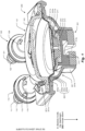
- Fig. 1 is a vertical section of an integral pump assembly 200 showing a diaphragm assembly 201 mounted to a pump-valving assembly 101 in diastole mode, in which the chamber 102 is being filled.
- the pump-valving assembly 101 includes an inlet ball check valve assembly 110 and an outlet ball check valve assembly 120.
- the integral pump assembly 200 includes a pump housing 221 including a neck 221b in which the coupler 214 reciprocates as the diaphragm 202 reciprocates.
- the neck 221b is configured to maintain axial alignment of the coupler 214 and (via physical features, such as flattened sides) is also configured to maintain rotational alignment of the coupler 214.
- the pump-valving assembly 101 is discussed in further detail in the related application, referenced above, bearing attorney docket number 4747/1001.
- the diaphragm 202 As the diaphragm 202 is pulled down (in a direction away from the chamber 102 ) to cause filling of the chamber 102, it creates a negative pressure that draws fluid into the chamber 102 through the inlet port 111. Similarly, as the diaphragm 202 is pushed up in a direction into the chamber 102, it creates a positive pressure that causes flow of the fluid out of the chamber 102 through the outlet port 121. (In these figures, like numbered items correspond to similar components across different figures.)
- the edge mount 202a diaphragm 202 (consisting of inside surface 202b, reinforcing layer 202c, and outside surface 202d ) is part of a diaphragm assembly 201 including, among other things, diastolic plate 203, attachment stem 212, systolic distribution brace 211, and retaining ring 213.
- the diastolic plate 203 is embedded within the diaphragm 202, over the reinforcing layer 202c and mechanically coupled to the inside surface 202b of the diaphragm 202 and to the attachment stem 212.
- the attachment stem 212 is also coupled to the systolic distribution brace 211 through retaining ring 213.
- the outer diameter of the diastolic plate 203 is smaller than the diameter of the interior of the rounded outer edge 211a of the systolic distribution brace 211.
- Construction of the diaphragm assembly 201 therefore is not symmetric for pulling and pushing.
- stress is placed on a more concentrated portion of the diaphragm 202 (defined largely by the diameter of the diastolic plate 203 ) than in pushing, which occurs more broadly through the attachment stem 212 and the systolic distribution brace 211, which has a larger diameter than the diastolic plate 203 and is configured to cup the diaphragm 202.
- the diaphragm 202 must tolerate millions of strokes. With each stroke, the diaphragm 202 is subjected to physical movement and oscillation between positive and negative pressures within the chamber 102. In order to increase life expectancy, the ideal diaphragm 202 should be as thin as possible, because thin materials minimize bending stresses during flexure.
- a thin elastomeric material, used for the inside surface 202b and outside surface 202d of the diaphragm 202 has excellent flexibility, but low tensile strength. This low tensile strength causes the elastomeric material to excessively strain during the oscillating positive and negative pressures seen during operation, eventually leading to failure.
- the reinforcing layer 202c provides the tensile strength required to withstand these pressure fluctuations while maintaining the flexibility of the elastomeric layers 203 and 202d.
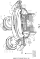
- Fig. 2 is a vertical section of an integral pump assembly 200 showing a diaphragm assembly 201 mounted to a pump-valving assembly 101 in systole mode, in which the chamber 102 is being emptied.
- the systolic distribution brace 211 is mounted beneath the diaphragm 202 and mechanically coupled to the diastolic plate 203 through the attachment stem 212.
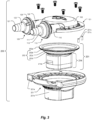
- Fig. 3 is an exploded perspective view, from the side, of an integral pump assembly 200, showing a pump-valving assembly 101, chamber 102, inlet port 111, first tapered tract 112, second tapered tract 116, outlet port 121, fourth tapered tract 121, outlet rib 125, third tapered tract 126, diaphragm assembly 201, edge mount 202a diaphragm 202 (composed of inside surface 202b, reinforcing layer 202c, and outside surface 202d ), pump housing 221 (with peripheral flange 221a, neck 221b, and compliant member 221c. Items 101-126 are discussed in further detail in the related application, referenced above, bearing attorney docket number 4747/1001.
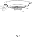
- Fig. 4 is a vertical section of a diaphragm 202 (composed of edge mount 202a, inside surface 202b, reinforcing layer 202c, and outside surface 202d ), also showing the diastolic plate 203 and attachment stem 212.
- the structure of a pulsatile pump in accordance with various embodiments of the present invention can usefully reflect attributes of the human heart.
- the human heart is preload sensitive-the heart cannot "pull" blood into the left ventricle; it can only allow the blood available to flow naturally into the ventricle.
- the human heart is also afterload sensitive in that it is responsive to the compliance and resistance in the downstream vasculature and doesn't exert excess force on the blood, which could damage the vasculature.
- the left ventricle cannot deliver blood that isn't in the ventricle when it contracts; there is a limited bolus of blood that it can deliver.
- the pump-valving assembly 101 has similar attributes of inherent safety: it is preload and afterload sensitive, and it is limited in both the volume of blood it can deliver and the force at which it can deliver that bolus of blood.
- the pump-valving assembly 101 allows gravity filling from the venous reservoir, exerting minimal negative pressure.
- the linear motor that powers the pump valving assembly is limited by design. In consequence the pump valving assembly cannot overpressure the downstream tubing or vasculature, instead delivering less than the volume of blood in the pump chamber 102, thereby only delivering as much volume as the vasculature can receive.
- the pump-valving assembly 101 is analogous to a left ventricle of the human heart; the inlet ball check valve assembly 110 used in various embodiments hereof is analogous to a mitral valve; and the outlet ball check valve assembly 120 used in various embodiments hereto is analogous to an aortic valve.
- the inlet 110 and outlet 120 ball check valve assemblies are passive and require a slight reversal of flow to close. This slight reversal of flow mimics the slight reversal that occurs when the aortic valve of the human heart closes.
Landscapes
- Health & Medical Sciences (AREA)
- Engineering & Computer Science (AREA)
- Heart & Thoracic Surgery (AREA)
- Mechanical Engineering (AREA)
- Cardiology (AREA)
- Life Sciences & Earth Sciences (AREA)
- Biomedical Technology (AREA)
- Hematology (AREA)
- Anesthesiology (AREA)
- Animal Behavior & Ethology (AREA)
- General Health & Medical Sciences (AREA)
- Public Health (AREA)
- Veterinary Medicine (AREA)
- General Engineering & Computer Science (AREA)
- Reciprocating Pumps (AREA)
- External Artificial Organs (AREA)
Claims (6)
- Membranbaugruppe (201) für eine pulsierende Fluidpumpe, umfassend:eine an der Kante montierte flexible Membran (202), die eine innere Oberfläche (202b) zum Kontaktieren eines Fluids aufweist, um gepumpt zu werden, eine äußere Oberfläche (202d), die der Umgebungsluft ausgesetzt ist, wobei die Membran konfiguriert ist, zyklisch zwischen einem Diastolenmodus und einem Systolenmodus zu operieren;eine systolische Verteilungsabstützung (211), die einen maximalen Radialumfang und eine innere Wand aufweist, die konfiguriert ist, einen Abschnitt der äußeren Oberfläche der Membran zu umschließen;eine diastolische Platte (203), die in der Membran eingebettet ist, einen maximalen Radialumfang aufweist und mechanisch mit einem Abschnitt der inneren Oberfläche der Membran gekoppelt ist;wobei der maximale Radialumfang der systolischen Verteilungsabstützung an einer Peripherie davon größer ist als der maximale Radialumfang der diastolischen Platte, und die systolische Verteilungsabstützung, die diastolische Platte und die Membran mechanisch miteinander verbunden sind, sodass:(i) im Verlauf des Systolenmodus die Membran die Peripherie der systolischen Verteilungsabstützung überhängt und eine Kraft über den maximalen Radialumfang der systolischen Verteilungsabstützung angewendet wird, sodass Spannung auf die Membran um die Peripherie der systolischen Verteilungsabstützung erzeugt wird, und(ii) im Verlauf des Diastolenmodus eine Kraft über den maximalen Radialumfang der diastolischen Platte angewendet wird, sodass Spannung auf die Membran um die diastolische Platte erzeugt wird, wobei die verschiedenen Radialumfänge der systolischen Verteilungsabstützung und der diastolischen Platte verschiedene Verteilungen der Kraft auf die Membran im Verlauf dieser zwei Modi bewirken, sodass Belastung auf die Membran verteilt und Dehnung auf die Membran im Verlauf eines Pumpzyklus verringert wird.
- Membranbaugruppe nach Anspruch 1, wobei die Membran eine Verstärkungsschicht (202c) aufweist, die zwischen der systolischen Verteilungsabstützung und der diastolischen Platte angeordnet ist
- Membran nach Anspruch 1, wobei die systolische Verteilungsabstützung eine abgerundete äußere Kante (211a) aufweist
und die Membran konfiguriert ist, über den maximalen Radialumfang der systolischen Verteilungsabstützung und über die abgerundete äußere Kante zu rollen. - Membranbaugruppe nach Anspruch 1, wobei die innere Wand der systolischen Verteilungsabstützung, die konfiguriert ist, den Abschnitt der äußeren Oberfläche der Membran zu umschließen, in einem stumpfen Winkel angeordnet ist.
- Membranbaugruppe nach Anspruch 1, wobei die diastolische Platte eine Abschrägung aufweist.
- Membranbaugruppe nach Anspruch 1, wobei die diastolische Platte eine Abschrägung in einem Winkel aufweist, der im Allgemeinen dem stumpfen Winkel der inneren Wand der systolischen Verteilungsabstützung entspricht.
Applications Claiming Priority (1)
| Application Number | Priority Date | Filing Date | Title |
|---|---|---|---|
| PCT/US2021/019253 WO2022182333A1 (en) | 2021-02-23 | 2021-02-23 | Diaphragm assembly for a pulsatile fluid pump |
Publications (2)
| Publication Number | Publication Date |
|---|---|
| EP4297841A1 EP4297841A1 (de) | 2024-01-03 |
| EP4297841B1 true EP4297841B1 (de) | 2025-02-12 |
Family
ID=74875357
Family Applications (1)
| Application Number | Title | Priority Date | Filing Date |
|---|---|---|---|
| EP21712361.1A Active EP4297841B1 (de) | 2021-02-23 | 2021-02-23 | Membrananordnung für eine pulsierende fluidpumpe |
Country Status (4)
| Country | Link |
|---|---|
| EP (1) | EP4297841B1 (de) |
| JP (1) | JP7634729B2 (de) |
| AU (1) | AU2021429965A1 (de) |
| WO (1) | WO2022182333A1 (de) |
Citations (1)
| Publication number | Priority date | Publication date | Assignee | Title |
|---|---|---|---|---|
| CN113048040A (zh) * | 2019-12-26 | 2021-06-29 | 中核建中核燃料元件有限公司 | 一种输送高密度介质的柱塞隔膜泵 |
Family Cites Families (8)
| Publication number | Priority date | Publication date | Assignee | Title |
|---|---|---|---|---|
| US2954738A (en) * | 1957-11-08 | 1960-10-04 | Honeywell Regulator Co | Diaphragm pump |
| JPS5396202U (de) * | 1977-01-08 | 1978-08-04 | ||
| JPS61157186U (de) * | 1985-03-22 | 1986-09-29 | ||
| US5092879A (en) * | 1988-02-17 | 1992-03-03 | Jarvik Robert K | Intraventricular artificial hearts and methods of their surgical implantation and use |
| US5349896A (en) * | 1993-06-14 | 1994-09-27 | W. L. Gore & Associates, Inc. | Pump diaphragm |
| US7107837B2 (en) | 2002-01-22 | 2006-09-19 | Baxter International Inc. | Capacitance fluid volume measurement |
| CA2476473C (en) | 2002-02-21 | 2013-02-19 | Design Mentor, Inc. | Fluid pump |
| DE102010009670B4 (de) | 2010-02-27 | 2013-09-19 | Knf Neuberger Gmbh | Membranpumpe |
-
2021
- 2021-02-23 EP EP21712361.1A patent/EP4297841B1/de active Active
- 2021-02-23 WO PCT/US2021/019253 patent/WO2022182333A1/en not_active Ceased
- 2021-02-23 AU AU2021429965A patent/AU2021429965A1/en active Pending
- 2021-02-23 JP JP2023575494A patent/JP7634729B2/ja active Active
Patent Citations (1)
| Publication number | Priority date | Publication date | Assignee | Title |
|---|---|---|---|---|
| CN113048040A (zh) * | 2019-12-26 | 2021-06-29 | 中核建中核燃料元件有限公司 | 一种输送高密度介质的柱塞隔膜泵 |
Also Published As
| Publication number | Publication date |
|---|---|
| JP2024507413A (ja) | 2024-02-19 |
| EP4297841A1 (de) | 2024-01-03 |
| WO2022182333A1 (en) | 2022-09-01 |
| JP7634729B2 (ja) | 2025-02-21 |
| AU2021429965A1 (en) | 2023-09-21 |
Similar Documents
| Publication | Publication Date | Title |
|---|---|---|
| CN103476332B (zh) | 流量控制阀及具有流量控制阀的血压信息测定装置 | |
| EP0628138B1 (de) | Selbstregelnde blutpumpe | |
| US20040013548A1 (en) | Pump | |
| US11608822B2 (en) | Diaphragm assembly for a pulsatile fluid pump | |
| US12173704B2 (en) | Disposable dual-action reciprocating pump assembly | |
| JP7634729B2 (ja) | パルス状流体ポンプのためのダイヤフラムアセンブリ | |
| US9828989B2 (en) | Device for delivering liquid at a stable flow rate | |
| US8834343B2 (en) | Heart support device | |
| US12188469B2 (en) | Using silicone o-rings in dual action irrigation pump | |
| US20240011472A1 (en) | Using balloon as damper for port of a reciprocating pump | |
| US11547846B2 (en) | Pump-valving assembly for a pulsatile fluid pump | |
| CN110966167B (zh) | 一种压电微泵 | |
| US12085066B2 (en) | Pulsatile fluid pump system | |
| US20250332333A1 (en) | Implantable pump device for pumping a body fluid | |
| CN214092250U (zh) | 一种复合隔膜结构及压电隔膜泵 | |
| EP4298345B1 (de) | Pumpen-ventil-anordnung für eine pumpe mit pulsierender flüssigkeit | |
| CN117605657A (zh) | 一种液体输送装置 |
Legal Events
| Date | Code | Title | Description |
|---|---|---|---|
| STAA | Information on the status of an ep patent application or granted ep patent |
Free format text: STATUS: UNKNOWN |
|
| STAA | Information on the status of an ep patent application or granted ep patent |
Free format text: STATUS: THE INTERNATIONAL PUBLICATION HAS BEEN MADE |
|
| PUAI | Public reference made under article 153(3) epc to a published international application that has entered the european phase |
Free format text: ORIGINAL CODE: 0009012 |
|
| STAA | Information on the status of an ep patent application or granted ep patent |
Free format text: STATUS: REQUEST FOR EXAMINATION WAS MADE |
|
| 17P | Request for examination filed |
Effective date: 20230905 |
|
| AK | Designated contracting states |
Kind code of ref document: A1 Designated state(s): AL AT BE BG CH CY CZ DE DK EE ES FI FR GB GR HR HU IE IS IT LI LT LU LV MC MK MT NL NO PL PT RO RS SE SI SK SM TR |
|
| DAV | Request for validation of the european patent (deleted) | ||
| DAX | Request for extension of the european patent (deleted) | ||
| GRAP | Despatch of communication of intention to grant a patent |
Free format text: ORIGINAL CODE: EPIDOSNIGR1 |
|
| STAA | Information on the status of an ep patent application or granted ep patent |
Free format text: STATUS: GRANT OF PATENT IS INTENDED |
|
| INTG | Intention to grant announced |
Effective date: 20240904 |
|
| GRAS | Grant fee paid |
Free format text: ORIGINAL CODE: EPIDOSNIGR3 |
|
| GRAA | (expected) grant |
Free format text: ORIGINAL CODE: 0009210 |
|
| STAA | Information on the status of an ep patent application or granted ep patent |
Free format text: STATUS: THE PATENT HAS BEEN GRANTED |
|
| RIN1 | Information on inventor provided before grant (corrected) |
Inventor name: MURPHY, MATTHEW J. Inventor name: POITRAS, JAMES W. Inventor name: KOENIG, GEORGE Inventor name: VINCENT, DOUGLAS E. |
|
| AK | Designated contracting states |
Kind code of ref document: B1 Designated state(s): AL AT BE BG CH CY CZ DE DK EE ES FI FR GB GR HR HU IE IS IT LI LT LU LV MC MK MT NL NO PL PT RO RS SE SI SK SM TR |
|
| REG | Reference to a national code |
Ref country code: GB Ref legal event code: FG4D |
|
| REG | Reference to a national code |
Ref country code: CH Ref legal event code: EP |
|
| P01 | Opt-out of the competence of the unified patent court (upc) registered |
Free format text: CASE NUMBER: APP_3936/2025 Effective date: 20250124 |
|
| REG | Reference to a national code |
Ref country code: DE Ref legal event code: R096 Ref document number: 602021025983 Country of ref document: DE |
|
| REG | Reference to a national code |
Ref country code: IE Ref legal event code: FG4D |
|
| PGFP | Annual fee paid to national office [announced via postgrant information from national office to epo] |
Ref country code: AT Payment date: 20250417 Year of fee payment: 5 |
|
| REG | Reference to a national code |
Ref country code: NL Ref legal event code: MP Effective date: 20250212 |
|
| PG25 | Lapsed in a contracting state [announced via postgrant information from national office to epo] |
Ref country code: RS Free format text: LAPSE BECAUSE OF FAILURE TO SUBMIT A TRANSLATION OF THE DESCRIPTION OR TO PAY THE FEE WITHIN THE PRESCRIBED TIME-LIMIT Effective date: 20250512 |
|
| PG25 | Lapsed in a contracting state [announced via postgrant information from national office to epo] |
Ref country code: FI Free format text: LAPSE BECAUSE OF FAILURE TO SUBMIT A TRANSLATION OF THE DESCRIPTION OR TO PAY THE FEE WITHIN THE PRESCRIBED TIME-LIMIT Effective date: 20250212 |
|
| PG25 | Lapsed in a contracting state [announced via postgrant information from national office to epo] |
Ref country code: PL Free format text: LAPSE BECAUSE OF FAILURE TO SUBMIT A TRANSLATION OF THE DESCRIPTION OR TO PAY THE FEE WITHIN THE PRESCRIBED TIME-LIMIT Effective date: 20250212 |
|
| PG25 | Lapsed in a contracting state [announced via postgrant information from national office to epo] |
Ref country code: ES Free format text: LAPSE BECAUSE OF FAILURE TO SUBMIT A TRANSLATION OF THE DESCRIPTION OR TO PAY THE FEE WITHIN THE PRESCRIBED TIME-LIMIT Effective date: 20250212 |
|
| REG | Reference to a national code |
Ref country code: LT Ref legal event code: MG9D |
|
| PG25 | Lapsed in a contracting state [announced via postgrant information from national office to epo] |
Ref country code: IS Free format text: LAPSE BECAUSE OF FAILURE TO SUBMIT A TRANSLATION OF THE DESCRIPTION OR TO PAY THE FEE WITHIN THE PRESCRIBED TIME-LIMIT Effective date: 20250612 Ref country code: NO Free format text: LAPSE BECAUSE OF FAILURE TO SUBMIT A TRANSLATION OF THE DESCRIPTION OR TO PAY THE FEE WITHIN THE PRESCRIBED TIME-LIMIT Effective date: 20250512 |
|
| PG25 | Lapsed in a contracting state [announced via postgrant information from national office to epo] |
Ref country code: NL Free format text: LAPSE BECAUSE OF FAILURE TO SUBMIT A TRANSLATION OF THE DESCRIPTION OR TO PAY THE FEE WITHIN THE PRESCRIBED TIME-LIMIT Effective date: 20250212 |
|
| PG25 | Lapsed in a contracting state [announced via postgrant information from national office to epo] |
Ref country code: HR Free format text: LAPSE BECAUSE OF FAILURE TO SUBMIT A TRANSLATION OF THE DESCRIPTION OR TO PAY THE FEE WITHIN THE PRESCRIBED TIME-LIMIT Effective date: 20250212 |
|
| PG25 | Lapsed in a contracting state [announced via postgrant information from national office to epo] |
Ref country code: LV Free format text: LAPSE BECAUSE OF FAILURE TO SUBMIT A TRANSLATION OF THE DESCRIPTION OR TO PAY THE FEE WITHIN THE PRESCRIBED TIME-LIMIT Effective date: 20250212 Ref country code: PT Free format text: LAPSE BECAUSE OF FAILURE TO SUBMIT A TRANSLATION OF THE DESCRIPTION OR TO PAY THE FEE WITHIN THE PRESCRIBED TIME-LIMIT Effective date: 20250612 |
|
| PG25 | Lapsed in a contracting state [announced via postgrant information from national office to epo] |
Ref country code: GR Free format text: LAPSE BECAUSE OF FAILURE TO SUBMIT A TRANSLATION OF THE DESCRIPTION OR TO PAY THE FEE WITHIN THE PRESCRIBED TIME-LIMIT Effective date: 20250513 Ref country code: BG Free format text: LAPSE BECAUSE OF FAILURE TO SUBMIT A TRANSLATION OF THE DESCRIPTION OR TO PAY THE FEE WITHIN THE PRESCRIBED TIME-LIMIT Effective date: 20250212 |
|
| REG | Reference to a national code |
Ref country code: AT Ref legal event code: MK05 Ref document number: 1765517 Country of ref document: AT Kind code of ref document: T Effective date: 20250212 |
|
| PG25 | Lapsed in a contracting state [announced via postgrant information from national office to epo] |
Ref country code: SE Free format text: LAPSE BECAUSE OF FAILURE TO SUBMIT A TRANSLATION OF THE DESCRIPTION OR TO PAY THE FEE WITHIN THE PRESCRIBED TIME-LIMIT Effective date: 20250212 |
|
| REG | Reference to a national code |
Ref country code: CH Ref legal event code: PL |
|
| PG25 | Lapsed in a contracting state [announced via postgrant information from national office to epo] |
Ref country code: SM Free format text: LAPSE BECAUSE OF FAILURE TO SUBMIT A TRANSLATION OF THE DESCRIPTION OR TO PAY THE FEE WITHIN THE PRESCRIBED TIME-LIMIT Effective date: 20250212 |
|
| PG25 | Lapsed in a contracting state [announced via postgrant information from national office to epo] |
Ref country code: DK Free format text: LAPSE BECAUSE OF FAILURE TO SUBMIT A TRANSLATION OF THE DESCRIPTION OR TO PAY THE FEE WITHIN THE PRESCRIBED TIME-LIMIT Effective date: 20250212 |
|
| PG25 | Lapsed in a contracting state [announced via postgrant information from national office to epo] |
Ref country code: LU Free format text: LAPSE BECAUSE OF NON-PAYMENT OF DUE FEES Effective date: 20250223 |
|
| PG25 | Lapsed in a contracting state [announced via postgrant information from national office to epo] |
Ref country code: AT Free format text: LAPSE BECAUSE OF FAILURE TO SUBMIT A TRANSLATION OF THE DESCRIPTION OR TO PAY THE FEE WITHIN THE PRESCRIBED TIME-LIMIT Effective date: 20250212 |
|
| PG25 | Lapsed in a contracting state [announced via postgrant information from national office to epo] |
Ref country code: CH Free format text: LAPSE BECAUSE OF NON-PAYMENT OF DUE FEES Effective date: 20250228 |
|
| PG25 | Lapsed in a contracting state [announced via postgrant information from national office to epo] |
Ref country code: EE Free format text: LAPSE BECAUSE OF FAILURE TO SUBMIT A TRANSLATION OF THE DESCRIPTION OR TO PAY THE FEE WITHIN THE PRESCRIBED TIME-LIMIT Effective date: 20250212 Ref country code: CZ Free format text: LAPSE BECAUSE OF FAILURE TO SUBMIT A TRANSLATION OF THE DESCRIPTION OR TO PAY THE FEE WITHIN THE PRESCRIBED TIME-LIMIT Effective date: 20250212 |
|
| PG25 | Lapsed in a contracting state [announced via postgrant information from national office to epo] |
Ref country code: RO Free format text: LAPSE BECAUSE OF FAILURE TO SUBMIT A TRANSLATION OF THE DESCRIPTION OR TO PAY THE FEE WITHIN THE PRESCRIBED TIME-LIMIT Effective date: 20250212 |
|
| PG25 | Lapsed in a contracting state [announced via postgrant information from national office to epo] |
Ref country code: SK Free format text: LAPSE BECAUSE OF FAILURE TO SUBMIT A TRANSLATION OF THE DESCRIPTION OR TO PAY THE FEE WITHIN THE PRESCRIBED TIME-LIMIT Effective date: 20250212 |
|
| REG | Reference to a national code |
Ref country code: DE Ref legal event code: R097 Ref document number: 602021025983 Country of ref document: DE |
|
| REG | Reference to a national code |
Ref country code: BE Ref legal event code: MM Effective date: 20250228 |
|
| PLBE | No opposition filed within time limit |
Free format text: ORIGINAL CODE: 0009261 |
|
| STAA | Information on the status of an ep patent application or granted ep patent |
Free format text: STATUS: NO OPPOSITION FILED WITHIN TIME LIMIT |
|
| PG25 | Lapsed in a contracting state [announced via postgrant information from national office to epo] |
Ref country code: MC Free format text: LAPSE BECAUSE OF FAILURE TO SUBMIT A TRANSLATION OF THE DESCRIPTION OR TO PAY THE FEE WITHIN THE PRESCRIBED TIME-LIMIT Effective date: 20250212 |
|
| PG25 | Lapsed in a contracting state [announced via postgrant information from national office to epo] |
Ref country code: BE Free format text: LAPSE BECAUSE OF NON-PAYMENT OF DUE FEES Effective date: 20250228 |
|
| PG25 | Lapsed in a contracting state [announced via postgrant information from national office to epo] |
Ref country code: IE Free format text: LAPSE BECAUSE OF NON-PAYMENT OF DUE FEES Effective date: 20250223 |
|
| 26N | No opposition filed |
Effective date: 20251113 |
|
| PG25 | Lapsed in a contracting state [announced via postgrant information from national office to epo] |
Ref country code: CY Free format text: LAPSE BECAUSE OF FAILURE TO SUBMIT A TRANSLATION OF THE DESCRIPTION OR TO PAY THE FEE WITHIN THE PRESCRIBED TIME-LIMIT Effective date: 20250212 |
|
| PG25 | Lapsed in a contracting state [announced via postgrant information from national office to epo] |
Ref country code: LT Free format text: LAPSE BECAUSE OF FAILURE TO SUBMIT A TRANSLATION OF THE DESCRIPTION OR TO PAY THE FEE WITHIN THE PRESCRIBED TIME-LIMIT Effective date: 20250212 |
|
| PG25 | Lapsed in a contracting state [announced via postgrant information from national office to epo] |
Ref country code: TR Free format text: LAPSE BECAUSE OF FAILURE TO SUBMIT A TRANSLATION OF THE DESCRIPTION OR TO PAY THE FEE WITHIN THE PRESCRIBED TIME-LIMIT Effective date: 20250212 |
|
| PGFP | Annual fee paid to national office [announced via postgrant information from national office to epo] |
Ref country code: GB Payment date: 20260420 Year of fee payment: 6 |
|
| PGFP | Annual fee paid to national office [announced via postgrant information from national office to epo] |
Ref country code: IT Payment date: 20260428 Year of fee payment: 6 |
|
| PGFP | Annual fee paid to national office [announced via postgrant information from national office to epo] |
Ref country code: DE Payment date: 20260414 Year of fee payment: 6 |
|
| PGFP | Annual fee paid to national office [announced via postgrant information from national office to epo] |
Ref country code: FR Payment date: 20260421 Year of fee payment: 6 |