EP4297624B1 - Reinigungskopf - Google Patents
Reinigungskopf Download PDFInfo
- Publication number
- EP4297624B1 EP4297624B1 EP22705113.3A EP22705113A EP4297624B1 EP 4297624 B1 EP4297624 B1 EP 4297624B1 EP 22705113 A EP22705113 A EP 22705113A EP 4297624 B1 EP4297624 B1 EP 4297624B1
- Authority
- EP
- European Patent Office
- Prior art keywords
- agitator
- cleaner head
- elements
- agitator elements
- cleaner
- Prior art date
- Legal status (The legal status is an assumption and is not a legal conclusion. Google has not performed a legal analysis and makes no representation as to the accuracy of the status listed.)
- Active
Links
Images


Classifications
-
- A—HUMAN NECESSITIES
- A47—FURNITURE; DOMESTIC ARTICLES OR APPLIANCES; COFFEE MILLS; SPICE MILLS; SUCTION CLEANERS IN GENERAL
- A47L—DOMESTIC WASHING OR CLEANING; SUCTION CLEANERS IN GENERAL
- A47L9/00—Details or accessories of suction cleaners, e.g. mechanical means for controlling the suction or for effecting pulsating action; Storing devices specially adapted to suction cleaners or parts thereof; Carrying-vehicles specially adapted for suction cleaners
- A47L9/02—Nozzles
- A47L9/04—Nozzles with driven brushes or agitators
- A47L9/0405—Driving means for the brushes or agitators
-
- A—HUMAN NECESSITIES
- A47—FURNITURE; DOMESTIC ARTICLES OR APPLIANCES; COFFEE MILLS; SPICE MILLS; SUCTION CLEANERS IN GENERAL
- A47L—DOMESTIC WASHING OR CLEANING; SUCTION CLEANERS IN GENERAL
- A47L9/00—Details or accessories of suction cleaners, e.g. mechanical means for controlling the suction or for effecting pulsating action; Storing devices specially adapted to suction cleaners or parts thereof; Carrying-vehicles specially adapted for suction cleaners
- A47L9/02—Nozzles
- A47L9/04—Nozzles with driven brushes or agitators
- A47L9/0461—Dust-loosening tools, e.g. agitators, brushes
- A47L9/0466—Rotating tools
-
- A—HUMAN NECESSITIES
- A47—FURNITURE; DOMESTIC ARTICLES OR APPLIANCES; COFFEE MILLS; SPICE MILLS; SUCTION CLEANERS IN GENERAL
- A47L—DOMESTIC WASHING OR CLEANING; SUCTION CLEANERS IN GENERAL
- A47L5/00—Structural features of suction cleaners
-
- A—HUMAN NECESSITIES
- A47—FURNITURE; DOMESTIC ARTICLES OR APPLIANCES; COFFEE MILLS; SPICE MILLS; SUCTION CLEANERS IN GENERAL
- A47L—DOMESTIC WASHING OR CLEANING; SUCTION CLEANERS IN GENERAL
- A47L5/00—Structural features of suction cleaners
- A47L5/12—Structural features of suction cleaners with power-driven air-pumps or air-compressors, e.g. driven by motor vehicle engine vacuum
- A47L5/22—Structural features of suction cleaners with power-driven air-pumps or air-compressors, e.g. driven by motor vehicle engine vacuum with rotary fans
- A47L5/24—Hand-supported suction cleaners
- A47L5/26—Hand-supported suction cleaners with driven dust-loosening tools
-
- A—HUMAN NECESSITIES
- A47—FURNITURE; DOMESTIC ARTICLES OR APPLIANCES; COFFEE MILLS; SPICE MILLS; SUCTION CLEANERS IN GENERAL
- A47L—DOMESTIC WASHING OR CLEANING; SUCTION CLEANERS IN GENERAL
- A47L9/00—Details or accessories of suction cleaners, e.g. mechanical means for controlling the suction or for effecting pulsating action; Storing devices specially adapted to suction cleaners or parts thereof; Carrying-vehicles specially adapted for suction cleaners
- A47L9/02—Nozzles
- A47L9/04—Nozzles with driven brushes or agitators
- A47L9/0405—Driving means for the brushes or agitators
- A47L9/0411—Driving means for the brushes or agitators driven by electric motor
-
- A—HUMAN NECESSITIES
- A47—FURNITURE; DOMESTIC ARTICLES OR APPLIANCES; COFFEE MILLS; SPICE MILLS; SUCTION CLEANERS IN GENERAL
- A47L—DOMESTIC WASHING OR CLEANING; SUCTION CLEANERS IN GENERAL
- A47L9/00—Details or accessories of suction cleaners, e.g. mechanical means for controlling the suction or for effecting pulsating action; Storing devices specially adapted to suction cleaners or parts thereof; Carrying-vehicles specially adapted for suction cleaners
- A47L9/02—Nozzles
- A47L9/04—Nozzles with driven brushes or agitators
- A47L9/0427—Gearing or transmission means therefor
-
- A—HUMAN NECESSITIES
- A47—FURNITURE; DOMESTIC ARTICLES OR APPLIANCES; COFFEE MILLS; SPICE MILLS; SUCTION CLEANERS IN GENERAL
- A47L—DOMESTIC WASHING OR CLEANING; SUCTION CLEANERS IN GENERAL
- A47L9/00—Details or accessories of suction cleaners, e.g. mechanical means for controlling the suction or for effecting pulsating action; Storing devices specially adapted to suction cleaners or parts thereof; Carrying-vehicles specially adapted for suction cleaners
- A47L9/02—Nozzles
- A47L9/04—Nozzles with driven brushes or agitators
- A47L9/0455—Bearing means therefor
-
- A—HUMAN NECESSITIES
- A47—FURNITURE; DOMESTIC ARTICLES OR APPLIANCES; COFFEE MILLS; SPICE MILLS; SUCTION CLEANERS IN GENERAL
- A47L—DOMESTIC WASHING OR CLEANING; SUCTION CLEANERS IN GENERAL
- A47L9/00—Details or accessories of suction cleaners, e.g. mechanical means for controlling the suction or for effecting pulsating action; Storing devices specially adapted to suction cleaners or parts thereof; Carrying-vehicles specially adapted for suction cleaners
- A47L9/02—Nozzles
- A47L9/04—Nozzles with driven brushes or agitators
- A47L9/0461—Dust-loosening tools, e.g. agitators, brushes
- A47L9/0466—Rotating tools
- A47L9/0477—Rolls
Definitions
- the present invention relates to a cleaner head for a vacuum cleaner.
- the present invention also relates to a vacuum cleaner comprising the cleaner head.
- a vacuum cleaner typically comprises a main body containing a dirt and dust separating apparatus, a cleaner head connected to the main body and having a suction opening, and a motor-driven fan unit for drawing dirt-bearing air through the opening and the cleaner head, and into the main body of the vacuum cleaner.
- the suction opening is directed downward to face the floor surface to be cleaned.
- the dirt-bearing air is conveyed to the separating apparatus so that dirt and dust can be separated from the air before the air is expelled to the atmosphere.
- the separating apparatus can include one or more of a filter, a filter bag and a cyclonic arrangement.
- a driven agitator may be mounted for rotation within a suction cavity of the cleaner head. Rotation of the agitator may be driven by an electric motor powered by a power supply derived from the main body of the vacuum cleaner. The agitator sweeps dust rearward through the suction opening of the cleaner head.
- DE 10 2007 006654 A1 describes a vacuum cleaner attachment according to the preamble of claim 1 having two brushes 16 that are plugged onto the drive shafts 8 and extend towards the respective side end region of the suction chamber 5.
- a cleaner head for a vacuum cleaner.
- the cleaner head is configured to apply suction to a horizontal surface to be cleaned by the vacuum cleaner.
- the cleaner head comprises first and second agitator elements, each being mounted for rotation about a respective axis.
- Each agitator element comprises a first, free end and a second end.
- Each agitator element has a shape which tapers towards the first end in a direction along the axis of rotation.
- the first and second agitator elements are cantilevered from opposing sides of a hub portion of the cleaner head at their respective second ends.
- Each agitator element is arranged such that the position of the axis at the first end of each agitator element is further forwards than the position of the axis at the second end of each agitator element.
- the agitator elements are effectively angled forwards, towards the front of the cleaner head and away from the rear of the cleaner head where the outlet is located. It will be appreciated that many cleaner heads have a clearly defined front and rear and that the forward direction will be understood as such in that context. It may for example be that the forward direction corresponds to the direction in which a forward stroke would be performed when using the vacuum cleaner to which the cleaner head is attached.
- the forward direction may alternatively or additionally be defined as the direction that is apparent if one considers that the region in which suction is applied is rearward of the agitator elements typically.
- the forward direction may alternatively or additionally be defined as the direction that is apparent if one considers that the agitator elements of this invention typically cause dirt and debris to be displaced in a rearward direction from the horizontal surface to be cleaned.
- the forward direction may be defined in relation to the orientation of the cleaner head when cleaning a horizontal surface.
- the forward direction may be parallel to such a horizontal surface.
- the axes of the agitator elements may be considered as being canted forwards.
- the angle at which the tapered external surface of each agitator element tapers may be equal to the angle by which the axis of the agitator element is angled forwards (optionally, within +/- 20%, say - or possibly within +/- 10%).
- the angle by which the axis of the agitator element is angled forwards may be less than 45 degrees and may be within the range of 10 degrees to 30 degrees.
- the tapered profile of the agitator elements which may be generally frusto-conical in shape, is at least partially compensated for. Therefore, when the cleaner head is pushed up against an obstacle, such as a wall or skirting board, an unagitated region of the surface to be cleaned near the first ends of the agitator elements may be reduced or possibly eliminated.
- the configuration is preferably such that, in the case when the cleaner head is pushed up against an obstacle having a vertical flat surface which is directly in front of and facing towards the cleaner head (e.g.
- each agitator element is the same distance away from the vertical surface, when the agitator elements are symmetrically shaped and symmetrically arranged), there is a unitary region of contact/agitation between the vertical surface and the two agitator elements (e.g. no gap between the respective regions agitated by the two agitator elements of the cleaner head).
- the frontmost portions of the external surfaces of both agitator elements lie in a single plane perpendicular to the horizontal surface when the cleaner head is applying suction thereto. In this manner, when the cleaner head is pushed up against an obstacle, such as a wall or skirting board, an unagitated region of the surface near the first ends of the agitator elements is eliminated.
- the cleaner head further comprises a sole plate in which a suction opening is formed. It may be that the frontmost portions of the external surfaces of both agitator elements lie in a single plane perpendicular to the plane of the sole plate.
- the cleaner head may be configured such that, in use, the sole plate is typically maintained parallel to the surface to be cleaned.
- the frontmost portions of the second ends of the agitator elements are directly adjacent to each other, and the rearmost portions of the second ends of the agitator elements are spaced apart.
- the external surfaces of the agitator elements comprise a felt-like covering.
- the felt-like covering may comprise an arrangement of many fine tufts standing on end, which may for example have a fluffy texture or appearance.
- the external surfaces of the agitator elements comprise bristles, for example upstanding bristles arranged around the agitator elements, which may be in the form of helical strips of bristles.
- the external surfaces of the agitator elements comprise an absorbent material such as sponge.
- Such agitator elements may be arranged to function as mop pads to absorb spilled liquids and/or to perform wet cleaning of a hard floor surface.
- the agitator elements may have the same overall shape.
- the agitator elements may be symmetrically shaped.
- the agitator elements may be symmetrically arranged.
- the cleaner head further comprises a drive for driving rotation of the agitator elements.
- the drive may comprise first and second motors, the first motor being arranged to drive rotation of the first agitator element, and the second motor being arranged to drive rotation of the second agitator element.
- each motor is disposed at least partially within the core of its respective agitator element. This provides for a compact arrangement.
- the first and second motors are arranged back-to-back and counter rotating, such that in use the first and second agitator elements rotate in the same direction.
- the drive further comprises first and second gears (e.g. reduction gears) arranged to change (e.g. reduce) the output speeds of the first and second motors respectively, the first and second gears being disposed within the cores the first and second agitator elements respectively.
- first and second gears e.g. reduction gears
- the drive comprises a single motor arranged to drive rotation of both the first and second agitator elements via respective first and second transmissions.
- Such transmissions may be at least partly disposed within the cores the first and second agitator elements respectively.
- each agitator element is arranged such that when the cleaner head is applying suction to the horizontal surface, the position of the axis at the first end of the element is closer to the surface than the position of the axis at the second end of the element.
- the agitator elements are effectively angled downwards, towards the surface to be cleaned by the vacuum cleaner and away from a top housing portion of the cleaner head.
- the tapered profile of the agitator elements which may be generally frusto-conical in shape, is at least partially compensated for. As such, a larger portion of the outer surface of each agitator element will be in contact the surface during use.
- a gap which would otherwise likely be present between the lowermost portions of the two agitator elements at their second ends is reduced in size.
- a larger region of the surface between the agitator elements is agitated by the cleaner head, and preferably such that there is a unitary region of contact/agitation between the surface to be cleaned and the two agitator elements (e.g. no gap between the respective regions agitated by the two agitator elements of the cleaner head).
- the axes of the agitator elements may be considered as being canted downwards.
- each agitator element is parallel to the horizontal surface when the cleaner head is applying suction thereto. In this manner, in use the lowermost surface each agitator element will be fully in contact with the surface being cleaned along its whole length.
- the angle at which the tapered external surface of each agitator element tapers may be equal to the angle by which the axis of the agitator element is angled downwards (optionally, within +/- 20%, say - or possibly within +/- 10%).
- the angle at which the tapered external surface of each agitator element tapers may be less than 45 degrees and may be within the range of 10 degrees to 30 degrees.
- the angle by which the axis of the agitator element is angled downwards may be less than 45 degrees and may be within the range of 10 degrees to 30 degrees.
- a vacuum cleaner comprising a cleaner head according to the first aspect.
- Figure 1 shows a hand-held vacuum cleaner 2 according to an embodiment of the invention and comprising a main body 4, a wand 6 and a cleaner head 20.
- the main body 4 comprises a separating system 10, in the form of a cyclonic separator, a motor and impeller (not visible) arranged to draw air through the separating system 10, and a power supply 12, in the form of a battery, for powering the motor.
- the main body 4 has a handle 14 which is gripped by a user, and a clean air outlet 16 through which air that has passed through the separating system 10 is discharged.
- the wand 6 is attached at one end to the main body 4 and at the other end to the cleaner head 20. The wand 6 provides fluid communication between the cleaner head 20 and the separating system 10, and supports the cleaner head 20 during use.
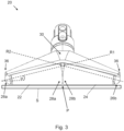
- FIG. 2 shows a cleaner head 20 according to embodiments of the invention.
- the cleaner head 20 comprises a first agitator element 22 and a second agitator element 24.
- the first and second agitator elements 22, 24 are each mounted for rotation about respective axes R1, R2.
- Each agitator element 22, 24 comprises a first, free end 26a, 26b and a second end 28a, 28b at which they are mounted to the cleaner head 20.
- Each agitator element has a shape which tapers towards the first end 26a, 26b in a direction along the axis of rotation R1, R2.
- the agitator elements 22, 24 are generally frusto-conical in shape. However, it should be appreciated that a portion of one or both agitator elements 22, 24 may not be tapered.
- the shape of one or both agitator elements 22, 24 may consist of a cylindrical portion combined with a frusto-conical portion.
- the first and second agitator elements 22, 24 are cantilevered from opposing sides of a hub portion 30 of the cleaner head 20 at their respective second ends 28a, 28b.
- the hub portion 30 is at a laterally central position with respect to the overall cleaner head 20, although this may not always be the case.
- the hub portion 30 could be offset laterally relative to the laterally central part of the cleaner head 20.
- the cleaner head 20 has a housing 32, which at least partially defines a suction chamber comprising an outlet 34 for expulsion of air and debris towards the vacuum cleaner 2.
- the suction chamber is delimited at the front by the agitator elements 22, 24.
- the housing 32 comprises side openings 36, adjacent the first end 26a, 26b of each agitator element 22, 24. The functions of these side openings 36 are described below.
- the external surfaces of the agitator elements comprise a felt-like covering with, in some embodiments, upstanding helical strips of bristles.
- each agitator element 22, 24 is arranged such that when the cleaner head 20 is applying suction to the horizontal surface S to be cleaned (e.g. hard flooring), the position of the axis R1, R2 at the first end 26a, 26b of each agitator element 22, 24 is closer to the surface S than the position of the axis R1, R2 at the second end 28a, 28b of each agitator element 22, 24. Therefore the agitator elements 22, 24 are effectively angled downwards (e.g. canted downwards), towards the surface S to be cleaned by the vacuum cleaner 2.
- the axes R1, R2 of both agitator elements 22, 24 are angled downwards by the same angle ⁇ .
- the downwards angling of the agitator elements 22, 24 is such that the lowermost portion of the external surface of each agitator element 22, 24 is parallel to the horizontal surface S when the cleaner head 20 is applying suction thereto. Furthermore, there is substantially no gap between the lowermost portions of the agitator elements 22, 24 at their second ends 28a, 28b, i.e. the lowermost portions of the agitator elements 22, 24 are in contact at their second ends 28a, 28b. This means that there is very little, if any, unagitated region of the surface S between the two agitator elements 22, 24 (i.e. in the region marked "P" in Figure 3 ).
- the respective regions on the floor agitated by the two agitator elements touch each other so that there is effectively a single unitary (elongate) region agitated by the cleaner head on the floor at any given time.
- this condition (the lowermost portions of the agitator elements being parallel to the floor) will be achieved when the agitator elements 22, 24 are angled downwards by an angle ⁇ which is equal to half the cone angle of the frusto-conical agitator elements 22, 24.
- the tapering of the conical shape of the external surface of each agitator element has a taper angle which is equal to half the cone angle and thus in the illustrated embodiment the same as the angle ⁇ by which the axis of the agitator element is angled downwards.
- angle ⁇ is about 15 degrees.
- the external surface of each agitator element may have some resilience/deformability and that surfaces to be cleaned in practice are rarely perfectly flat, it will be appreciated that the lowermost portion need not be exactly parallel, in the strict mathematical sense, to the horizontal surface for the agitator element to cause agitation of the surface to be cleaned along substantially the entire length of the external surface of the element arranged to perform such agitating.
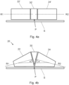
- Figures 4a and 4b illustrate reducing the gap between the lowermost portions of the agitator elements 22, 24 at their second ends 28a, 28b (i.e. in the region marked "P" in Figure 3 ).
- Figure 4a shows a front view of a cleaner head, comprising a pair of cylindrical (i.e. not tapered) agitator elements 22', 24' which are cantilevered from a hub 30'. Due to the presence of the hub 30', there is a region P of the surface S underneath the hub 30' which is not agitated by either of the agitator elements 22', 24'.
- Figure 4b is a simplified version of Figure 3 , and shows a front view of a cleaner head 20 according to embodiments of the invention (i.e.
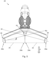
- FIG. 5 which is an underside view of the cleaner head 20, illustrates how in embodiments each agitator element 22, 24 is arranged such that the position of the axis R1, R2 at the first end 26a, 26b of each agitator element 22, 24 is further forwards than the position of the axis R1, R2 at the second end 28a, 28b of each agitator element 22, 24. Therefore, the agitator elements 22, 24 are effectively angled forwards, towards the front of the cleaner head 20 and away from the outlet 34, i.e. they are angled in a direction corresponding to a forward cleaning stroke being performed using the vacuum cleaner 2 to which the cleaner head 20 is attached.
- the forward direction is shown in Figure 5 by an arrow F.
- the tapered profile of the agitator elements 22, 24, which in the illustrated embodiment are frusto-conical in shape, is at least partially compensated for, as described below.
- the axes R1, R2 of both agitator elements 22, 24 are angled forwards by the same angle ⁇ , such that the frontmost portions of the external surfaces of both agitator elements 22, 24 lie in a single plane perpendicular to the horizontal surface S when the cleaner head 20 is applying suction thereto.
- the unagitated regions of the surface S near the first ends 26a, 26b of the agitator elements 22, 24 are reduced.
- the unagitated regions of the surface S near the first ends 26a, 26b of the agitator elements 22, 24 may be minimised.
- the free ends (the first ends) 26a, 26b of the frusto-conical agitator elements 22, 24 may then both be as close to the wall as possible, leaving very little if any unagitated regions of the surface S near the wall.
- Such an arrangement may be useful if agitation of a vertical surface is required, for example when cleaning stairs, as there may be an uninterrupted line of contact with the vertical surface from the free end 26a of one element to the free end 26b of the other agitator element.
- the tapering of the conical shape of the external surface of each agitator element has a taper angle which is the same as the angle ⁇ by which the axis of the agitator element is angled forwards. In this embodiment that angle ⁇ is about 15 degrees.
- Figure 6a shows a simplified top-down view of a cleaner head 20, where each agitator element 22, 24 is arranged such that the position of the axis R1, R2 at the first end 26a, 26b of each agitator element 22, 24 is no further forwards than the position of the axis R1, R2 at the second end 28a, 28b of each agitator element 22, 24.
- an object W such as a wall or skirting board
- the frontmost portions of the agitator elements 22, 24 contact the object W, leaving gaps G1, G2 either side in which the surface S cannot be agitated without repositioning the cleaner head to approach from a different angle, e.g.
- Figure 6b is a simplified top-down view of the cleaner head 20 shown in Figure 5 , where the axes R1, R2 of both agitator elements 22, 24 are angled forwards by the same angle ⁇ , such that the frontmost portions of the external surfaces of both agitator elements 22, 24 lie in a single plane perpendicular to the horizontal surface S when the cleaner head 20 is applying suction thereto.
- the unagitated regions G1, G2 of the surface S near the first ends 26a, 26b of the agitator elements 22, 24 are minimised.
- each agitator element may have some resilience/deformability and that walls, skirting boards and the like are rarely perfectly flat and vertical, it will be appreciated that the frontmost portions of the external surfaces of both agitator elements need not be exactly straight and need not lie completely within a single plane, in the strict mathematical sense, in order for the agitator elements to get sufficiently close to the wall or skirting board to provide the advantage mentioned above.
- the agitator elements may be angled downwards but not forwards, whereas in other embodiments, the agitator elements may be angled forwards but not downwards. Furthermore, it should be appreciated that the agitator elements may not necessarily be angled downwards by an angle corresponding to half the cone angle of the agitator elements and the agitator elements may not necessarily be angled forwards by an angle corresponding to half the cone angle of the agitator elements. In embodiments, the agitator elements may have different lengths and/or different cone angles. Accordingly, the first and second agitator elements may be angled forwards and/or downwards by different angles. In some embodiments, the cleaner head 20 comprises a sole plate in which a suction opening is formed. The lowermost portion of the external surface of each agitator element may be parallel to the sole plate and/or the frontmost portions of the external surfaces of both agitator elements may lie in a single plane perpendicular to the plane of the sole plate.
- Cleaner heads 20 have a cleaner head housing 32 comprising side openings 36 adjacent the first end 26a, 26b of each agitator element 22, 24. These side openings 36 are visible in Figures 2 , 3 5 and 7 .
- the side openings 36 provide two separate functions. Firstly, in embodiments they provide a suction path from the first ends 26a, 26b of the agitator elements 22, 24 towards the cleaner head outlet 34. In this manner, debris, such as hair, which migrates towards the first ends 26a, 26b of the tapered agitator elements 22, 24, potentially falling off the first ends completely, can be sucked up by the vacuum cleaner 2.
- the first ends 26a, 26b of the agitator elements 22, 24 can project into or through the side openings 36. This enables the first ends 26a, 26b of the agitator elements 22, 24 to protrude beyond the footprint of the cleaner head housing 32, providing for a greater agitation width and up to the edge cleaning.
- Figure 8 illustrates schematically a front view of a cleaner head 20 in which the first ends 26a, 26b of the agitator elements 22, 24 project through the side openings 36, such that the first end of each the agitator element protrudes beyond the footprint of the cleaner head housing 32.
- the side openings 36 may provide only one of these two functions.
- the side opening 36 may provide a suction path in the manner described, but the first ends 26a, 26b of the agitator elements may not project into or through the side opening 36.
- the first end 26a, 26b of the agitator elements 22, 24 may project into or through the side opening 36, but the first end 26a, 26b may be sized such that it substantially fills the side opening 36, thereby delimiting the suction chamber. In this manner, no such suction path is provided.
- only one agitator element may be provided, whilst still benefiting from the advantages provided by the side opening 36 in the cleaner head housing 32.
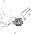
- the cleaner head 20 further comprises a drive for driving rotation of the agitator elements 22, 24.
- the drive comprises a first motor 38 arranged to drive rotation of the first agitator element 22 and a second motor 40 arranged to drive rotation of the second 24 agitator element.
- Each motor is disposed (at least partially) within the core of its respective agitator element 22, 24. It should be appreciated that the motors can be accommodated fully within the agitator cores or may project slightly outward towards the hub 30 region between the two cantilevered agitator elements 22, 24.
- the first and second motors 38, 40 are arranged back-to-back and are therefore arranged to be counter rotating (i.e. the output shaft of one motor rotates clockwise whilst the output shaft of the other motor rotates counter clockwise), such that in use the first and second agitator elements 22, 24 rotate in the same direction.
- the drive further comprises first and second gears 42, 44 (e.g. reduction gears) arranged to change (e.g. reduce) the output speeds of the first and second motors 38, 40 respectively.
- the gears 42, 44 are disposed (at least partially) within the cores of their respective agitator elements 22, 24.
- the drive comprises a single motor 46 arranged to drive rotation of both the first and second agitator elements 22, 24 via respective first and second transmissions 48, 50.
Landscapes
- Engineering & Computer Science (AREA)
- Mechanical Engineering (AREA)
- Nozzles For Electric Vacuum Cleaners (AREA)
Claims (14)
- Reinigungskopf (20) für einen Staubsauger (2), wobei der Reinigungskopf dazu ausgelegt ist, eine Saugkraft auf eine vom Staubsauger zu reinigende horizontale Fläche (S) aufzubringen, wobei der Reinigungskopf Folgendes umfasst:
ein erstes und zweites Rührwerkelement (22, 24), die jeweils zur Drehung um eine jeweilige Achse (R1, R2) montiert sind, und wobei:
jedes Rührwerkelement ein erstes, freies Ende (26a, 26b) und ein zweites Ende (28a, 28b) umfasst, dadurch gekennzeichnet, dass das erste und zweite Rührwerkelement (22, 24) von entgegengesetzten Seiten eines Nabenabschnitts (30) des Reinigungskopfes (1) an deren jeweiligen zweiten Enden (28a, 28b) auskragen, wobei jedes Rührwerkelement (22, 24) eine Form aufweist, die sich in eine Richtung entlang der Drehachse (R1, R2) zum ersten Ende (26a, 26b) hin verjüngt, und wobei jedes Rührwerkelement (22, 24) derart angeordnet ist, dass die Position der Achse (R1, R2) am ersten Ende (26a, 26b) jedes Rührwerkelements (22, 24) weiter vorn angeordnet ist als die Position der Achse (R1, R2) am zweiten Ende (28a, 28b) jedes Rührwerkelements (22, 24). - Reinigungskopf nach Anspruch 1, wobei die vordersten Abschnitte der Außenflächen beider Rührwerkelemente (22, 24) in einer einzelnen Ebene senkrecht zur horizontalen Fläche (S) liegen, wenn der Reinigungskopf (20) darauf eine Saugkraft aufbringt.
- Reinigungskopf nach Anspruch 1 oder 2, wobei der Reinigungskopf (20) ferner eine Grundplatte umfasst, in der eine Saugöffnung ausgebildet ist, und wobei die vordersten Abschnitte der Außenflächen beider Rührwerkelemente (22, 24) in einer einzelnen Ebene senkrecht zur Ebene der Grundplatte liegen.
- Reinigungskopf nach einem der vorstehenden Ansprüche, wobei die vordersten Abschnitte der zweiten Enden (28a, 28b) der Rührwerkelemente (22, 24) direkt aneinander angrenzen und die hintersten Abschnitte der zweiten Enden der Rührwerkelemente voneinander beabstandet sind.
- Reinigungskopf nach einem der vorstehenden Ansprüche, wobei die Außenflächen der Rührwerkelemente (22, 24) einen filzartigen Bezug umfassen.
- Reinigungskopf nach einem der vorstehenden Ansprüche, wobei die Außenflächen der Rührwerkelemente (22, 24) aufrechte, schraubenförmige Borstenstreifen umfassen.
- Reinigungskopf nach einem der vorstehenden Ansprüche, ferner umfassend einen Antrieb (38, 40, 46) zum Antreiben der Drehung der Rührwerkelemente (22, 24).
- Reinigungskopf nach Anspruch 7, wobei der Antrieb einen ersten und zweiten Motor (38, 40) umfasst, wobei der erste Motor dazu angeordnet ist, die Drehung des ersten Rührwerkelements (22) anzutreiben, und wobei der zweite Motor dazu angeordnet ist, die Drehung des zweiten Rührwerkelements (24) anzutreiben.
- Reinigungskopf nach Anspruch 8, wobei jeder Motor (38, 40) zumindest teilweise im Kern seines jeweiligen Rührwerkelements (22, 24) angeordnet ist.
- Reinigungskopf nach Anspruch 8 oder 9, wobei der erste und zweite Motor (38, 40) direkt hintereinander und gegensinnig drehend angeordnet sind, sodass sich das erste und zweite Rührwerkelement (22, 24) bei der Verwendung in dieselbe Richtung drehen.
- Reinigungskopf nach einem der Ansprüche 8 bis 10, wobei der Antrieb (38, 40) ferner ein erstes und zweites Zahnrad (42, 44) umfasst, die dazu angeordnet sind, die Ausgangsdrehzahl des ersten bzw. zweiten Motors zu verändern, wobei das erste und zweite Zahnrad in den Kernen des ersten bzw. zweiten Rührwerkelements (22, 24) angeordnet sind.
- Reinigungskopf nach Anspruch 7, wobei der Antrieb einen einzelnen Motor (46) umfasst, der dazu angeordnet ist, die Drehung sowohl des ersten als auch des zweiten Rührwerkelements (22, 24) über ein jeweiliges erstens und zweites Getriebe (48, 50) anzutreiben.
- Reinigungskopf nach einem der vorstehenden Ansprüche, wobei jedes Rührwerkelement (22, 24) ferner derart angeordnet ist, dass, wenn der Reinigungskopf (20) eine Saugkraft auf die horizontale Fläche aufbringt, die Position der Achse (R1, R2) am ersten Ende (26a, 26b) des Elements näher an der Fläche ist als die Position der Achse am zweiten Ende (28a, 28b) des Elements.
- Staubsauger (2), einen Reinigungskopf (20) nach einem der vorstehenden Ansprüche umfassend.
Applications Claiming Priority (2)
| Application Number | Priority Date | Filing Date | Title |
|---|---|---|---|
| GB2102780.0A GB2604582B (en) | 2021-02-26 | 2021-02-26 | Cleaner Head |
| PCT/GB2022/050357 WO2022180362A1 (en) | 2021-02-26 | 2022-02-10 | Cleaner head |
Publications (2)
| Publication Number | Publication Date |
|---|---|
| EP4297624A1 EP4297624A1 (de) | 2024-01-03 |
| EP4297624B1 true EP4297624B1 (de) | 2025-03-12 |
Family
ID=75377447
Family Applications (1)
| Application Number | Title | Priority Date | Filing Date |
|---|---|---|---|
| EP22705113.3A Active EP4297624B1 (de) | 2021-02-26 | 2022-02-10 | Reinigungskopf |
Country Status (6)
| Country | Link |
|---|---|
| US (1) | US20240225387A9 (de) |
| EP (1) | EP4297624B1 (de) |
| KR (1) | KR20230147207A (de) |
| CN (1) | CN116940269A (de) |
| GB (1) | GB2604582B (de) |
| WO (1) | WO2022180362A1 (de) |
Families Citing this family (2)
| Publication number | Priority date | Publication date | Assignee | Title |
|---|---|---|---|---|
| GB2619035B (en) * | 2022-05-24 | 2024-08-28 | Dyson Technology Ltd | Cleaner head for a vacuum cleaner |
| USD1065731S1 (en) * | 2023-07-14 | 2025-03-04 | Guangdong Deerma Technology Co., Ltd. | Vacuum cleaner |
Family Cites Families (11)
| Publication number | Priority date | Publication date | Assignee | Title |
|---|---|---|---|---|
| JPS61194470U (de) * | 1985-05-24 | 1986-12-03 | ||
| US4653137A (en) * | 1986-02-20 | 1987-03-31 | Eugene Fleischhauer | Vacuum cleaner attachments |
| JPH0637806Y2 (ja) * | 1990-04-04 | 1994-10-05 | 俊文 生田 | 掃除機の吸込具 |
| DE102007006654A1 (de) * | 2007-02-10 | 2008-08-14 | Vorwerk & Co. Interholding Gmbh | Bürste, insbesondere Bürste zur Anordnung in einem Vorsatzgerät |
| JP2010110344A (ja) * | 2008-11-04 | 2010-05-20 | Panasonic Corp | 電気掃除機 |
| WO2016028243A1 (en) * | 2014-08-22 | 2016-02-25 | Tarman Diş Ti̇caret Anoni̇m Şi̇rketi̇ | Triangular profile double beater turbo sweeper head |
| KR101620235B1 (ko) * | 2014-12-10 | 2016-05-11 | 엘지전자 주식회사 | 청소기의 노즐 및 진공 청소기 |
| GB2569313B (en) * | 2017-12-12 | 2020-10-28 | Dyson Technology Ltd | A cleaner head for a vacuum cleaner |
| CN112334051B (zh) * | 2018-04-23 | 2022-05-27 | 尚科宁家运营有限公司 | 表面清洁装置的辅助驱动 |
| GB2584446B (en) * | 2019-06-03 | 2021-09-22 | Dyson Technology Ltd | A cleaner head for a vacuum cleaner |
| CN111012241A (zh) * | 2019-11-26 | 2020-04-17 | 西安和光明宸科技有限公司 | 一种手持式吸尘器 |
-
2021
- 2021-02-26 GB GB2102780.0A patent/GB2604582B/en active Active
-
2022
- 2022-02-10 EP EP22705113.3A patent/EP4297624B1/de active Active
- 2022-02-10 KR KR1020237032949A patent/KR20230147207A/ko active Pending
- 2022-02-10 CN CN202280017258.5A patent/CN116940269A/zh active Pending
- 2022-02-10 US US18/278,645 patent/US20240225387A9/en active Pending
- 2022-02-10 WO PCT/GB2022/050357 patent/WO2022180362A1/en not_active Ceased
Also Published As
| Publication number | Publication date |
|---|---|
| CN116940269A (zh) | 2023-10-24 |
| US20240130582A1 (en) | 2024-04-25 |
| GB2604582B (en) | 2023-08-09 |
| WO2022180362A1 (en) | 2022-09-01 |
| GB2604582A (en) | 2022-09-14 |
| GB202102780D0 (en) | 2021-04-14 |
| EP4297624A1 (de) | 2024-01-03 |
| US20240225387A9 (en) | 2024-07-11 |
| KR20230147207A (ko) | 2023-10-20 |
Similar Documents
| Publication | Publication Date | Title |
|---|---|---|
| US20240306869A1 (en) | Cleaner head | |
| US8448294B2 (en) | Cleaner head | |
| KR100493492B1 (ko) | 표면청소장치 | |
| US8484800B2 (en) | Cleaner head | |
| US20240138635A1 (en) | Cleaner head | |
| EP4297624B1 (de) | Reinigungskopf | |
| US8495790B2 (en) | Cleaner head | |
| JP2020517340A (ja) | クリーニングローラからごみくずを除去するためのコーミングユニットを有するクリーニング装置 | |
| GB2615960A (en) | Cleaner head | |
| GB2700194A (en) | Cleaner head | |
| GB2486441A (en) | A cleaner head | |
| GB2486444A (en) | Cleaner head |
Legal Events
| Date | Code | Title | Description |
|---|---|---|---|
| STAA | Information on the status of an ep patent application or granted ep patent |
Free format text: STATUS: UNKNOWN |
|
| STAA | Information on the status of an ep patent application or granted ep patent |
Free format text: STATUS: THE INTERNATIONAL PUBLICATION HAS BEEN MADE |
|
| PUAI | Public reference made under article 153(3) epc to a published international application that has entered the european phase |
Free format text: ORIGINAL CODE: 0009012 |
|
| STAA | Information on the status of an ep patent application or granted ep patent |
Free format text: STATUS: REQUEST FOR EXAMINATION WAS MADE |
|
| 17P | Request for examination filed |
Effective date: 20230814 |
|
| AK | Designated contracting states |
Kind code of ref document: A1 Designated state(s): AL AT BE BG CH CY CZ DE DK EE ES FI FR GB GR HR HU IE IS IT LI LT LU LV MC MK MT NL NO PL PT RO RS SE SI SK SM TR |
|
| DAV | Request for validation of the european patent (deleted) | ||
| DAX | Request for extension of the european patent (deleted) | ||
| GRAP | Despatch of communication of intention to grant a patent |
Free format text: ORIGINAL CODE: EPIDOSNIGR1 |
|
| STAA | Information on the status of an ep patent application or granted ep patent |
Free format text: STATUS: GRANT OF PATENT IS INTENDED |
|
| INTG | Intention to grant announced |
Effective date: 20241008 |
|
| GRAS | Grant fee paid |
Free format text: ORIGINAL CODE: EPIDOSNIGR3 |
|
| GRAA | (expected) grant |
Free format text: ORIGINAL CODE: 0009210 |
|
| STAA | Information on the status of an ep patent application or granted ep patent |
Free format text: STATUS: THE PATENT HAS BEEN GRANTED |
|
| RBV | Designated contracting states (corrected) |
Designated state(s): AL AT BE BG CH CY CZ DE DK EE ES FI FR GR HR HU IE IS IT LI LT LU LV MC MK MT NL NO PL PT RO RS SE SI SK SM TR |
|
| AK | Designated contracting states |
Kind code of ref document: B1 Designated state(s): AL AT BE BG CH CY CZ DE DK EE ES FI FR GR HR HU IE IS IT LI LT LU LV MC MK MT NL NO PL PT RO RS SE SI SK SM TR |
|
| P01 | Opt-out of the competence of the unified patent court (upc) registered |
Free format text: CASE NUMBER: APP_5656/2025 Effective date: 20250203 |
|
| REG | Reference to a national code |
Ref country code: CH Ref legal event code: EP |
|
| REG | Reference to a national code |
Ref country code: DE Ref legal event code: R096 Ref document number: 602022011709 Country of ref document: DE |
|
| REG | Reference to a national code |
Ref country code: IE Ref legal event code: FG4D |
|
| PG25 | Lapsed in a contracting state [announced via postgrant information from national office to epo] |
Ref country code: RS Free format text: LAPSE BECAUSE OF FAILURE TO SUBMIT A TRANSLATION OF THE DESCRIPTION OR TO PAY THE FEE WITHIN THE PRESCRIBED TIME-LIMIT Effective date: 20250612 |
|
| PG25 | Lapsed in a contracting state [announced via postgrant information from national office to epo] |
Ref country code: FI Free format text: LAPSE BECAUSE OF FAILURE TO SUBMIT A TRANSLATION OF THE DESCRIPTION OR TO PAY THE FEE WITHIN THE PRESCRIBED TIME-LIMIT Effective date: 20250312 |
|
| PG25 | Lapsed in a contracting state [announced via postgrant information from national office to epo] |
Ref country code: ES Free format text: LAPSE BECAUSE OF FAILURE TO SUBMIT A TRANSLATION OF THE DESCRIPTION OR TO PAY THE FEE WITHIN THE PRESCRIBED TIME-LIMIT Effective date: 20250312 |
|
| REG | Reference to a national code |
Ref country code: LT Ref legal event code: MG9D |
|
| PG25 | Lapsed in a contracting state [announced via postgrant information from national office to epo] |
Ref country code: NO Free format text: LAPSE BECAUSE OF FAILURE TO SUBMIT A TRANSLATION OF THE DESCRIPTION OR TO PAY THE FEE WITHIN THE PRESCRIBED TIME-LIMIT Effective date: 20250612 |
|
| PG25 | Lapsed in a contracting state [announced via postgrant information from national office to epo] |
Ref country code: HR Free format text: LAPSE BECAUSE OF FAILURE TO SUBMIT A TRANSLATION OF THE DESCRIPTION OR TO PAY THE FEE WITHIN THE PRESCRIBED TIME-LIMIT Effective date: 20250312 |
|
| REG | Reference to a national code |
Ref country code: NL Ref legal event code: MP Effective date: 20250312 |
|
| PG25 | Lapsed in a contracting state [announced via postgrant information from national office to epo] |
Ref country code: LV Free format text: LAPSE BECAUSE OF FAILURE TO SUBMIT A TRANSLATION OF THE DESCRIPTION OR TO PAY THE FEE WITHIN THE PRESCRIBED TIME-LIMIT Effective date: 20250312 |
|
| PG25 | Lapsed in a contracting state [announced via postgrant information from national office to epo] |
Ref country code: GR Free format text: LAPSE BECAUSE OF FAILURE TO SUBMIT A TRANSLATION OF THE DESCRIPTION OR TO PAY THE FEE WITHIN THE PRESCRIBED TIME-LIMIT Effective date: 20250613 Ref country code: BG Free format text: LAPSE BECAUSE OF FAILURE TO SUBMIT A TRANSLATION OF THE DESCRIPTION OR TO PAY THE FEE WITHIN THE PRESCRIBED TIME-LIMIT Effective date: 20250312 |
|
| REG | Reference to a national code |
Ref country code: AT Ref legal event code: MK05 Ref document number: 1774279 Country of ref document: AT Kind code of ref document: T Effective date: 20250312 |
|
| PG25 | Lapsed in a contracting state [announced via postgrant information from national office to epo] |
Ref country code: NL Free format text: LAPSE BECAUSE OF FAILURE TO SUBMIT A TRANSLATION OF THE DESCRIPTION OR TO PAY THE FEE WITHIN THE PRESCRIBED TIME-LIMIT Effective date: 20250312 |
|
| PG25 | Lapsed in a contracting state [announced via postgrant information from national office to epo] |
Ref country code: SE Free format text: LAPSE BECAUSE OF FAILURE TO SUBMIT A TRANSLATION OF THE DESCRIPTION OR TO PAY THE FEE WITHIN THE PRESCRIBED TIME-LIMIT Effective date: 20250312 |
|
| PG25 | Lapsed in a contracting state [announced via postgrant information from national office to epo] |
Ref country code: SM Free format text: LAPSE BECAUSE OF FAILURE TO SUBMIT A TRANSLATION OF THE DESCRIPTION OR TO PAY THE FEE WITHIN THE PRESCRIBED TIME-LIMIT Effective date: 20250312 |
|
| PG25 | Lapsed in a contracting state [announced via postgrant information from national office to epo] |
Ref country code: PT Free format text: LAPSE BECAUSE OF FAILURE TO SUBMIT A TRANSLATION OF THE DESCRIPTION OR TO PAY THE FEE WITHIN THE PRESCRIBED TIME-LIMIT Effective date: 20250714 |
|
| PG25 | Lapsed in a contracting state [announced via postgrant information from national office to epo] |
Ref country code: IT Free format text: LAPSE BECAUSE OF FAILURE TO SUBMIT A TRANSLATION OF THE DESCRIPTION OR TO PAY THE FEE WITHIN THE PRESCRIBED TIME-LIMIT Effective date: 20250312 Ref country code: PL Free format text: LAPSE BECAUSE OF FAILURE TO SUBMIT A TRANSLATION OF THE DESCRIPTION OR TO PAY THE FEE WITHIN THE PRESCRIBED TIME-LIMIT Effective date: 20250312 |
|
| PG25 | Lapsed in a contracting state [announced via postgrant information from national office to epo] |
Ref country code: AT Free format text: LAPSE BECAUSE OF FAILURE TO SUBMIT A TRANSLATION OF THE DESCRIPTION OR TO PAY THE FEE WITHIN THE PRESCRIBED TIME-LIMIT Effective date: 20250312 |
|
| PG25 | Lapsed in a contracting state [announced via postgrant information from national office to epo] |
Ref country code: EE Free format text: LAPSE BECAUSE OF FAILURE TO SUBMIT A TRANSLATION OF THE DESCRIPTION OR TO PAY THE FEE WITHIN THE PRESCRIBED TIME-LIMIT Effective date: 20250312 Ref country code: CZ Free format text: LAPSE BECAUSE OF FAILURE TO SUBMIT A TRANSLATION OF THE DESCRIPTION OR TO PAY THE FEE WITHIN THE PRESCRIBED TIME-LIMIT Effective date: 20250312 |
|
| PG25 | Lapsed in a contracting state [announced via postgrant information from national office to epo] |
Ref country code: RO Free format text: LAPSE BECAUSE OF FAILURE TO SUBMIT A TRANSLATION OF THE DESCRIPTION OR TO PAY THE FEE WITHIN THE PRESCRIBED TIME-LIMIT Effective date: 20250312 |
|
| PG25 | Lapsed in a contracting state [announced via postgrant information from national office to epo] |
Ref country code: SK Free format text: LAPSE BECAUSE OF FAILURE TO SUBMIT A TRANSLATION OF THE DESCRIPTION OR TO PAY THE FEE WITHIN THE PRESCRIBED TIME-LIMIT Effective date: 20250312 |
|
| PG25 | Lapsed in a contracting state [announced via postgrant information from national office to epo] |
Ref country code: IS Free format text: LAPSE BECAUSE OF FAILURE TO SUBMIT A TRANSLATION OF THE DESCRIPTION OR TO PAY THE FEE WITHIN THE PRESCRIBED TIME-LIMIT Effective date: 20250712 |
|
| REG | Reference to a national code |
Ref country code: DE Ref legal event code: R097 Ref document number: 602022011709 Country of ref document: DE |
|
| PG25 | Lapsed in a contracting state [announced via postgrant information from national office to epo] |
Ref country code: DK Free format text: LAPSE BECAUSE OF FAILURE TO SUBMIT A TRANSLATION OF THE DESCRIPTION OR TO PAY THE FEE WITHIN THE PRESCRIBED TIME-LIMIT Effective date: 20250312 |
|
| PLBE | No opposition filed within time limit |
Free format text: ORIGINAL CODE: 0009261 |
|
| STAA | Information on the status of an ep patent application or granted ep patent |
Free format text: STATUS: NO OPPOSITION FILED WITHIN TIME LIMIT |
|
| REG | Reference to a national code |
Ref country code: CH Ref legal event code: L10 Free format text: ST27 STATUS EVENT CODE: U-0-0-L10-L00 (AS PROVIDED BY THE NATIONAL OFFICE) Effective date: 20260121 |
|
| 26N | No opposition filed |
Effective date: 20251215 |