EP4297391A1 - Color adjustment apparatus, color adjustment method, and program - Google Patents
Color adjustment apparatus, color adjustment method, and program Download PDFInfo
- Publication number
- EP4297391A1 EP4297391A1 EP23176402.8A EP23176402A EP4297391A1 EP 4297391 A1 EP4297391 A1 EP 4297391A1 EP 23176402 A EP23176402 A EP 23176402A EP 4297391 A1 EP4297391 A1 EP 4297391A1
- Authority
- EP
- European Patent Office
- Prior art keywords
- image
- color
- difference signals
- color difference
- patches
- Prior art date
- Legal status (The legal status is an assumption and is not a legal conclusion. Google has not performed a legal analysis and makes no representation as to the accuracy of the status listed.)
- Granted
Links
Images





Classifications
-
- H—ELECTRICITY
- H04—ELECTRIC COMMUNICATION TECHNIQUE
- H04N—PICTORIAL COMMUNICATION, e.g. TELEVISION
- H04N9/00—Details of colour television systems
- H04N9/64—Circuits for processing colour signals
-
- G—PHYSICS
- G06—COMPUTING OR CALCULATING; COUNTING
- G06T—IMAGE DATA PROCESSING OR GENERATION, IN GENERAL
- G06T7/00—Image analysis
- G06T7/90—Determination of colour characteristics
-
- H—ELECTRICITY
- H04—ELECTRIC COMMUNICATION TECHNIQUE
- H04N—PICTORIAL COMMUNICATION, e.g. TELEVISION
- H04N1/00—Scanning, transmission or reproduction of documents or the like, e.g. facsimile transmission; Details thereof
- H04N1/46—Colour picture communication systems
- H04N1/56—Processing of colour picture signals
- H04N1/60—Colour correction or control
- H04N1/603—Colour correction or control controlled by characteristics of the picture signal generator or the picture reproducer
- H04N1/6052—Matching two or more picture signal generators or two or more picture reproducers
- H04N1/6055—Matching two or more picture signal generators or two or more picture reproducers using test pattern analysis
-
- H—ELECTRICITY
- H04—ELECTRIC COMMUNICATION TECHNIQUE
- H04N—PICTORIAL COMMUNICATION, e.g. TELEVISION
- H04N17/00—Diagnosis, testing or measuring for television systems or their details
- H04N17/002—Diagnosis, testing or measuring for television systems or their details for television cameras
-
- H—ELECTRICITY
- H04—ELECTRIC COMMUNICATION TECHNIQUE
- H04N—PICTORIAL COMMUNICATION, e.g. TELEVISION
- H04N17/00—Diagnosis, testing or measuring for television systems or their details
- H04N17/02—Diagnosis, testing or measuring for television systems or their details for colour television signals
-
- H—ELECTRICITY
- H04—ELECTRIC COMMUNICATION TECHNIQUE
- H04N—PICTORIAL COMMUNICATION, e.g. TELEVISION
- H04N23/00—Cameras or camera modules comprising electronic image sensors; Control thereof
- H04N23/80—Camera processing pipelines; Components thereof
- H04N23/84—Camera processing pipelines; Components thereof for processing colour signals
-
- H—ELECTRICITY
- H04—ELECTRIC COMMUNICATION TECHNIQUE
- H04N—PICTORIAL COMMUNICATION, e.g. TELEVISION
- H04N25/00—Circuitry of solid-state image sensors [SSIS]; Control thereof
- H04N25/60—Noise processing, e.g. detecting, correcting, reducing or removing noise
- H04N25/61—Noise processing, e.g. detecting, correcting, reducing or removing noise the noise originating only from the lens unit, e.g. flare, shading, vignetting or "cos4"
- H04N25/611—Correction of chromatic aberration
-
- G—PHYSICS
- G06—COMPUTING OR CALCULATING; COUNTING
- G06T—IMAGE DATA PROCESSING OR GENERATION, IN GENERAL
- G06T11/00—Two-dimensional [2D] image generation
- G06T11/10—Texturing; Colouring; Generation of textures or colours
-
- G—PHYSICS
- G06—COMPUTING OR CALCULATING; COUNTING
- G06T—IMAGE DATA PROCESSING OR GENERATION, IN GENERAL
- G06T2207/00—Indexing scheme for image analysis or image enhancement
- G06T2207/10—Image acquisition modality
- G06T2207/10024—Color image
-
- G—PHYSICS
- G06—COMPUTING OR CALCULATING; COUNTING
- G06T—IMAGE DATA PROCESSING OR GENERATION, IN GENERAL
- G06T2207/00—Indexing scheme for image analysis or image enhancement
- G06T2207/20—Special algorithmic details
- G06T2207/20092—Interactive image processing based on input by user
-
- G—PHYSICS
- G06—COMPUTING OR CALCULATING; COUNTING
- G06T—IMAGE DATA PROCESSING OR GENERATION, IN GENERAL
- G06T2207/00—Indexing scheme for image analysis or image enhancement
- G06T2207/20—Special algorithmic details
- G06T2207/20212—Image combination
Definitions
- the present invention relates to a color adjustment apparatus used for color matching of a plurality of image capturing apparatuses, a color adjustment method, and a program.
- a camera serving as a reference for color matching is referred to as a reference camera
- a camera serving as a target for the color matching is referred to as a target camera.
- a correction lookup table (referred to as a correction LUT) is generated based on the captured images.
- the correction LUT is correction information for matching the color of the image captured by the target camera with the color of the image captured by the reference camera. Thereafter, the color matching between the cameras is performed by applying the generated correction LUT to the target camera.
- Color matching accuracy after the color matching between cameras is typically verified by visually comparing the image captured by the reference camera and an image obtained by applying the correction LUT to the image captured by the target camera.
- the reference camera image and the target camera image captured for the color matching are different in a capturing field angle
- the images in areas other than the color chart are different.
- the color difference signals of the entire captured image are displayed as the vector scope image
- the color difference signals in the region other than the color chart are also displayed. Accordingly, a user cannot easily grasp color shift or color difference of the color chart used for color matching at a glance, and it is not possible to intelligibly display the color matching accuracy.
- the present invention provides a color adjustment apparatus that is capable of displaying color matching accuracy in a visually intelligible manner.
- a first aspect of the present invention provides a color adjustment apparatus as specified in claims 1 to 15.
- a second aspect of the present invention provides a color adjustment method as specified in claim 16.
- a third aspect of the present invention provides a program as specified in claim 17.
- FIG. 1 is a schematic view showing a configuration of a color adjustment system including a color adjustment apparatus according to a first embodiment of the present invention.
- the color adjustment system includes a control apparatus 102 as a color adjustment apparatus, a first image capturing apparatus 100, a second image capturing apparatus 101, and a display device 103.
- the control apparatus 102 include a CPU 102a, a ROM 102b, and a RAM 102c.
- the ROM 102b stores various programs and values used for control.
- the CPU 102a controls the entire system by running the programs stored in the ROM 102b.
- the RAM 102c provides a work area for the CPU 102a to perform a control program.
- the first image capturing apparatus 100 is a reference camera serving as a reference for performing color matching in a color matching process between the image capturing apparatuses.
- the second image capturing apparatus 101 is a target camera serving as a color matching target (correction target).
- Each of the image capturing apparatuses 100 and 101 transmits an image obtained by capturing an object to the control apparatus 102 via a video line. It should be noted that transmission of the captured image via the video line is not indispensable, and a configuration without the video line can be achieved.
- the captured image may be transferred via a recording medium such as a memory card, or the captured image may be transmitted and received by wireless communication.
- the image capturing apparatuses 100 and 101 which are arranged side-by-side, capture a color chart 105 for the color matching.
- the images captured by the image capturing apparatuses 100 and 101 are transmitted to the control apparatus 102.
- the color chart 105 a plurality of color patches having different colors (for example, three patches 301C, 302C, and 303C are shown) are arranged.
- the color patches are measurement images. It should be noted that the number of color patches is not limited.
- the image capturing apparatuses 100 and 101 may be captured one by one facing the color chart 105.
- the positions of the image capturing apparatuses in capturing images may be separated from each other as long as the images of the image capturing apparatuses 100 and 101 include the image of the color chart 105.
- the display device 103 displays a UI used when the control apparatus 102 generates the correction LUT and the confirmation image for confirming the effect of the correction LUT.
- the display device 103 is connected to the control apparatus 102 via a cable of a general image standard, such as HDMI (registered trademark) or DVI, and displays image information and other additional information on the screen.
- the control apparatus 102 causes the display device 103 to display the reference camera image, the target camera image before applying the correction LUT, the target camera image after applying the correction LUT, and color difference signals (vector scope).
- the control apparatus 102 executes an LUT generation process and a color difference signal plotting process of an input captured image.
- the LUT generation process will be described with reference to FIG. 2 to FIG. 7 .
- the functions of the color-patch-position determination unit 200, the color-patch-pixel-value extraction unit 201, and the LUT generation unit 202 are achieved by cooperation of the CPU 102a, ROM 102b, RAM 102c, etc. in the control apparatus 102.
- the reference camera image IMG_R and the target camera image IMG_T are input to the color-patch-position determination unit 200.
- the color-patch-position determination unit 200 receives designated positions of the patch images 301, 302, and 303 in the camera images IMG_R and IMG_T from the user via the UI.
- the user specifies a central position (centroid) or two or more vertices of the patch image 301, 302, and 303.
- the color-patch-position determination unit 200 determines extraction areas 301r, 302r, and 303r from the reference camera image IMG_R and determines extraction areas 301t, 302t, and 303t from the target camera image IMG_T based on the designated positions.
- the positions of the patch images 301, 302, and 303 may be automatically specified from the input captured images using an inference process using an object detection AI or a rule-based algorithm.
- the color patch pixel values PIXEL_VALUE_R, PIXEL_VALUE_T are input to the LUT generation unit 202.
- the LUT generation unit 202 generates a correction LUT based on the color patch pixel values PIXEL VALUE R and PIXEL_VALUE_T.
- the correction LUT is used to correct the color patch pixel values PIXEL_VALUE_T so as to match the color patch pixel values PIXEL_VALUE_R.
- FIG. 4 is a flowchart showing an LUT generation process. This process is achieved by the CPU 102a developing a program stored in the ROM 102b to the RAM 102c and executing the program.
- the LUT generation unit 202 obtains the color patch pixel values PIXEL_VALUE_R and PIXEL_VALUE_T from the color-patch-pixel-value extraction unit 201.
- the LUT generation unit 202 converts the RGB values of the color patch pixel values PIXEL_VALUE_R and PIXEL_VALUE_T into XYZ values.
- the RGB values are converted into the XYZ values by using the following formula 1, for example.
- X Y Z RGB ⁇ to ⁇ XYZ Conversion Matrix R G B
- the LUT generation unit 202 calculates a correction matrix M for matching the color of the target camera image to the color of the reference camera image.
- the correction matrix M is a matrix for correcting the XYZ values of the color patch of the target camera image to the XYZ values of the color patch of the reference camera image.
- the correction matrix M is calculated by the following formula 2 using the calculated arithmetic matrixes R and T.
- Correction Matrix M Arithmetic Matrix R Arithmetic Matrix T ⁇ 1
- the LUT generation unit 202 calculates corrected XYZ values using the converted XYZ values and the correction matrix M in the step S104. Then, the LUT generation unit 202 calculates the corrected RGB values (Out) from the corrected XYZ values using the inverse matrix of the RGB-to-XYZ transformation matrix. The calculated relationship between In and Out of the RGB values is generated as a corrected LUT 106 as 3D-LUT.
- FIG. 7 is a view showing an example of the correction LUT 106.
- the illustrated correction LUT includes 17 ⁇ 17 ⁇ 17 grid points and stores the corrected RGB values (Out) corresponding to the RGB values (In) of the grid points. It should be noted that the number of the grid points is not limited to the illustrated number. If the number of grid points is increased, the color matching accuracy will increase, but the scale of the process will increase. Conversely, if the number of grid points is made smaller, the scale of process will be smaller, but the color matching accuracy will be reduced. The user may appropriately determine these factors in consideration of cost effectiveness.
- the correction LUT is input to an LUT application unit 400 ( FIG. 8 ) described later.
- the number of the color patches included in the color chart 105 is three in this embodiment, the number is not limited to three. It is known that the accuracy increases as the number of colors used for generating the correction LUT increases. Since the calculation time increases as the number of color patches increases, the type and the number of patches of the color chart 105 used for the color matching may be selected in consideration of the trade-off between the accuracy and the calculation time.
- correction LUT is generated from two input captured images
- a configuration in which a correction LUT generated in advance is read may be employed.
- FIG. 8 is a functional block diagram showing the control apparatus 102 related to the color difference signal plotting process in the first embodiment.
- the control apparatus 102 includes the LUT application unit 400, a color difference signal conversion unit 401, and a color difference signal plotting unit 402 as functional units related to the color difference signal plotting process.
- the functions of the LUT application unit 400, the color difference signal conversion unit 401, and the color difference signal plotting unit 402 are achieved by the cooperation of the CPU 102a, ROM 102b, and RAM 102c in the control apparatus 102.
- the LUT application unit 400 as a second obtainment means obtains a target camera image IMG_T (second captured image).
- the LUT application unit 400 as a third obtainment means obtains the correction LUT 106 generated by the LUT generation unit 202 ( FIG. 2 ). As described above, the correction LUT 106 to be obtained may be generated in advance and input from the outside.
- the color difference signal conversion unit 401 as a first obtainment means obtains a reference camera image IMG_R (first captured image). In addition, the color difference signal conversion unit 401 obtains the post LUT-application target camera image IMG_T_LUT.
- the color difference signal conversion unit 401 as an output means converts the format of the camera images IMG_R, IMG_T_LUT from the RGB format into the YCbCr format using the following formula 3 and outputs them as color difference signals.
- the RGB-to-YCbCr conversion matrix may consist of values determined in accordance with an input color standard (BT.709 etc.).
- Y Cb Cr RGB ⁇ to ⁇ YCbCr Conversion Matrix R G B
- the vector scope images VEC_IMG_R and VEC_IMG_T are displayed side-by-side by dividing one screen into two or using two screens.
- the colors of the color patches included in the color chart 105 can be displayed in a pinpoint manner. Therefore, the color difference signals of each patch color can be compared in the pinpoint manner by comparing the image in FIG. 10A with the image in FIG. 10B , which allows the user to easily check the color coincidence of the colors in the color matching.
- the vector scope image VEC_IMG_R is generated based only on the color difference signals in the extraction areas 301r, 302r, and 303r corresponding to the patches in the color chart 105 among the reference camera image IMG_R.
- the vector scope image VEC_IMG_T is generated based only on the color difference signals of the extraction areas 301t, 302t, and 303t corresponding to the patches in the post LUT-application (post color matching) target camera image IMG_T_LUT.
- the vector scope images VEC_IMG_R and VEC_IMG_T are displayed side by side. Therefore, the color matching accuracy becomes visually recognizable.
- the image of color difference signals of the entire captured image ( FIG. 9 ) and the vector scope images ( FIG. 10A and FIG. 10B ) may be switched using a display mode switching UI (not shown). For example, when the user selects an "entire mode” for displaying the color difference signals of the entire captured image, the image in FIG. 9 is displayed. And when the user selects a "chart mode” for displaying only the color difference signals in the cut-out areas, the images in FIG. 10A and FIG. 10B are displayed.
- the extraction areas 301r, 302r, and 303r may be determined based on the field angle ratio of the color chart image included in the reference camera image IMG_R.
- the extraction areas 301t, 302t, and 303t may be determined based on the field angle ratio of the color chart image included in the target camera image IMG_T. For example, when the field angle ratio of the color chart is large, the cut-out area may be decreased. When the field angle ratio of the color chart is small, the cut-out area may be increased. In other words, when the field angle ratio is a second value larger than a first value, the cut-out area in the patch image is smaller than that where the field angle ratio is the first value.
- FIG. 11 is a functional block diagram showing a control apparatus 102 involved in a color difference signal plotting process in the second embodiment.
- the control apparatus 102 includes an LUT application unit 500, a color difference signal conversion unit 501, and a color difference signal plotting unit 502 as functional units related to the color difference signal plotting process.
- the basic functions of the LUT application unit 500, the color difference signal conversion unit 501, and the color difference signal plotting unit 502 are the same as those of the LUT application unit 400, the color difference signal conversion unit 401, and the color difference signal plotting unit 402 shown in FIG. 8 , respectively.
- the color difference signal plotting unit 502 is different from the color difference signal plotting unit 402, further generates a superimposed image VEC_IMG_RT. It should be noted that it is not indispensable to display the vector scope images VEC_IMG_R and VEC_IMG_T described in the first embodiment.
- the number of the color patches included in the color chart 105 is three (three colors). In FIG. 12A, FIG. 12B, and FIG. 12C , the number of the color patches is twenty (twenty colors). As described above, it is not indispensable to display the screens shown in FIG. 12A and FIG. 12B .
- the color difference signal plotting unit 502 plots the vector scope images VEC_IMG_R and VEC_IMG_T in mutually different colors. For example, the color difference signal plotting unit 502 plots the vector scope image VEC_IMG_R in white and the vector scope image VEC_IMG_T in black. The colors are not limited thereto.
- the color difference signal plotting unit 502 plots the vector scope image VEC_IMG_R (an upper hierarchical layer) so as to be superimposed on the vector scope image VEC_IMG_T. Therefore, only the vector scope image VEC IMG_R is visually recognized in a portion where display positions of both color difference signals are mutually overlapped with respect to colors having a small color shift. In the meantime, since display positions of color difference signals of two colors having a large color shift are separated from each other, the shifted color is conspicuous, and the shift of the color difference signals can be recognized at a glance.
- FIG. 12C the color difference signal plotting unit 502 plots the vector scope image VEC_IMG_R (an upper hierarchical layer) so as to be superimposed on the vector scope image VEC_IMG_T. Therefore, only the vector scope image VEC IMG_R is visually recognized in a portion where display positions of both color difference signals are mutually overlapped with respect to colors having a small color shift. In the meantime, since display positions of color difference signals
- the superimposed image VEC_IMG_RT in which vector scope images VEC_IMG_R and VEC_IMG_T are superimposed is displayed. Therefore, the same effect as that of the first embodiment can be achieved with respect to ease of visual recognition of the color matching accuracy.
- the color difference signal plotting unit 502 may determine plotting colors of the vector scope images VEC_IMG_R and VEC_IMG_T in accordance with the coincidence of these vector scope images for each color of a patch.
- the color difference signal plotting unit 502 uniformly determines the plotting color of the vector scope image VEC_IMG_R to be a predetermined color (e.g., white).
- the color difference signal plotting unit 502 determines the plotting color of the vector scope image VEC_IMG_T to be green for a color whose coincidence between the vector scope images VEC_IMG_R and VEC_IMG_T is higher than a predetermined value among the colors of the patches.
- the color difference signal plotting unit 502 determines the plotting color of the vector scope image VEC_IMG_T to be red for a color whose coincidence is lower than the predetermined value.
- the color difference signal plotting unit 502 may generate another superimposed image in which the color difference signals VEC INFO R of the reference camera image IMG_R and the color difference signals of the target camera image IMG_T before application of the correction LUT are superimposed. Then, the control apparatus 102 may switch and display the superimposed image VEC_IMG_RT and the other superimposed image. For example, when both the superimposed images are switched and displayed in response to a user instruction, the user can easily confirm the matching states of the colors before and after applying the correction LUT at a glance.
- a third embodiment of the present invention will now be described.
- a superimposed image in which an image indicating the target position of the color difference signals VEC_INFO_R for each color is superimposed on the color difference signals VEC_INFO_R is generated.
- Other configurations in this embodiment are the same as those in the second embodiment.
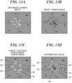
- FIG. 13A and FIG. 13B respectively show examples of the vector scope images VEC_IMG_R and VEC_IMG_T displayed on the screen.
- FIG. 13C is a view showing an example in which target rectangles K1 are displayed on a screen.
- FIG. 13D is a view showing an example a superimposed image in which the target rectangles K1 are superimposed on the vector scope image VEC_IMG_T displayed on the screen.
- a target rectangle K1 is an example of an image indicating a target position of the color difference signals VEC_INFO_R for each color.
- the target rectangle K1 is a frame indicating a predetermined area based on each target position. It should be noted that the predetermined area may be a fixed area.
- the target rectangles K1 may be provided corresponding to all colors. However, only the target rectangles corresponding to some predetermined colors are displayed in this embodiment. For example, the target rectangles K1 indicating target positions corresponding to red (R), green (G), blue (B), cyan (Cy), magenta (Mg), and yellow (Yl) among the patch colors are displayed.
- a superimposed image shown in FIG. 13D is generated by superimposing the image shown in FIG. 13C on the image shown in FIG. 13B .
- large shifts occur in the red (R) direction, the yellow (Yl) direction, and the cyan (Cy) direction.
- the superimposed image in which the target rectangles K1, which are images indicating the target positions of the color difference signals VEC_INFO_R for each color, are superimposed on the color difference signals VEC_INFO_R is generated and displayed. Therefore, the same effect as that of the first embodiment can be achieved with respect to ease of visual recognition of the color matching accuracy. In particular, the shift of the color difference signals can be visually recognized at a glance.
- the shape of the image indicating the target position is not limited to a rectangle as long as the shape allows the target position to be visually recognized.
- an arbitrary figure such as a circle, a triangle, or a rhombus, may be employed.
- it is not indispensable that the image indicating the target position is based on the center position.
- the area of the target rectangle K1 (the area of the image indicating the target position) may be determined based on a limit area in which a color difference can be recognized by human eyes.
- the image size of the target rectangle K1 can be determined in accordance with the visual recognition capability of human eyes.
- an area in which a person cannot visually recognize a color difference may be determined as the area of the image with respect to the median coordinate of the target position. In this way, the user can confirm the allowable color shift at a glance.
- the area in which a person cannot visually recognize the color difference can be determined based on the CIE2000.
- the target positions are displayed for six colors of red (R), green (G), blue (B), cyan (Cy), magenta (Mg), and yellow (Yl)
- other display methods may be employed.
- color pairs of the vector scope image VEC_IMG_T and the target rectangles K1 may be displayed in each of four quadrants divided by the Cb and Cr axes to be plotted. This makes it easy to visually recognize a shift from the target position without overlapping the colors. Further, when the user switches the display while designating the color to be checked, the user can check the shifts from the target positions for all the colors.
- a fourth embodiment of the present invention will now be described.
- display of color difference signals corresponding to a part of colors among a plurality of patch colors is limited (not displayed).
- Other configurations are the same as those of the first embodiment.
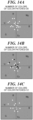
- FIG. 14A and FIG. 14B are schematic views showing the vector scope image VEC_IMG_R corresponding to the patches of 20 colors.
- color difference signals corresponding to colors to be displayed among the patches of 20 colors are shown in white, and color difference signals not to be displayed among the patches of 20 colors are shown in black.
- FIG. 14C is a view showing an example in which the vector scope image VEC IMG_R in which display of color difference signals corresponding to some colors is limited is displayed on the screen.
- FIG. 14A, FIG. 14B, and FIG. 14C show the generation and display of the vector scope image VEC_IMG_R as a representative, the vector scope image VEC_IMG_T is also subjected similarly.
- a color in which the color difference signals are close may be replaced by a single color.
- the number of colors in a portion selected by the user may be limited.
- Embodiment(s) of the present invention can also be realized by a computer of a system or apparatus that reads out and executes computer executable instructions (e.g., one or more programs) recorded on a storage medium (which may also be referred to more fully as a 'non-transitory computer-readable storage medium') to perform the functions of one or more of the above-described embodiment(s) and/or that includes one or more circuits (e.g., application specific integrated circuit (ASIC)) for performing the functions of one or more of the above-described embodiment(s), and by a method performed by the computer of the system or apparatus by, for example, reading out and executing the computer executable instructions from the storage medium to perform the functions of one or more of the above-described embodiment(s) and/or controlling the one or more circuits to perform the functions of one or more of the above-described embodiment(s).
- computer executable instructions e.g., one or more programs
- a storage medium which may also be referred to more fully as
- the computer may comprise one or more processors (e.g., central processing unit (CPU), micro processing unit (MPU)) and may include a network of separate computers or separate processors to read out and execute the computer executable instructions.
- the computer executable instructions may be provided to the computer, for example, from a network or the storage medium.
- the storage medium may include, for example, one or more of a hard disk, a random-access memory (RAM), a read only memory (ROM), a storage of distributed computing systems, an optical disk (such as a compact disc (CD), digital versatile disc (DVD), or Blu-ray Disc (BD) TM ), a flash memory device, a memory card, and the like.
Landscapes
- Engineering & Computer Science (AREA)
- Multimedia (AREA)
- Signal Processing (AREA)
- Health & Medical Sciences (AREA)
- General Health & Medical Sciences (AREA)
- Biomedical Technology (AREA)
- Computer Vision & Pattern Recognition (AREA)
- Theoretical Computer Science (AREA)
- General Physics & Mathematics (AREA)
- Physics & Mathematics (AREA)
- Image Processing (AREA)
- Color Television Image Signal Generators (AREA)
- Studio Devices (AREA)
Abstract
Description
- The present invention relates to a color adjustment apparatus used for color matching of a plurality of image capturing apparatuses, a color adjustment method, and a program.
- Conventionally, when images are captured using a plurality of cameras (image capturing apparatuses) at an image capturing site, color matching between the plurality of cameras is performed before capturing. Hereinafter, a camera serving as a reference for color matching is referred to as a reference camera, and a camera serving as a target for the color matching is referred to as a target camera.
- Generally, in color matching between cameras, a color chart placed in a capturing environment is captured by each of the reference camera and target camera, and then a correction lookup table (referred to as a correction LUT) is generated based on the captured images. The correction LUT is correction information for matching the color of the image captured by the target camera with the color of the image captured by the reference camera. Thereafter, the color matching between the cameras is performed by applying the generated correction LUT to the target camera.
- Color matching accuracy after the color matching between cameras is typically verified by visually comparing the image captured by the reference camera and an image obtained by applying the correction LUT to the image captured by the target camera. However, it is not easy to visually verify whether colors match one by one for each color in the images, and a display in which a coincidence of colors can be more intuitively recognized is desired.
- Therefore, as a method for checking the color matching accuracy after the color matching, a technique that plots color difference signals (CbCr pixel information of an image) on a screen to display as a vector scope image (for example,
Japanese Laid-Open Patent Publication (Kokai) No. 2011-217091 JP 2011-217091A - However, when the reference camera image and the target camera image captured for the color matching are different in a capturing field angle, the images in areas other than the color chart are different. Moreover, when the color difference signals of the entire captured image are displayed as the vector scope image, the color difference signals in the region other than the color chart are also displayed. Accordingly, a user cannot easily grasp color shift or color difference of the color chart used for color matching at a glance, and it is not possible to intelligibly display the color matching accuracy.
- The present invention provides a color adjustment apparatus that is capable of displaying color matching accuracy in a visually intelligible manner.
- Accordingly, a first aspect of the present invention provides a color adjustment apparatus as specified in claims 1 to 15.
- Accordingly, a second aspect of the present invention provides a color adjustment method as specified in
claim 16. - Accordingly, a third aspect of the present invention provides a program as specified in
claim 17. - According to the present invention, the color matching accuracy can be displayed in a visually intelligible manner.
- Further features of the present invention will become apparent from the following description of exemplary embodiments with reference to the attached drawings.
-
-
FIG. 1 is a schematic view showing a configuration of a color adjustment system including a color adjustment apparatus. -
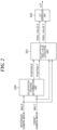
FIG. 2 is a functional block diagram showing a controller involved in a LUT generation process. -
FIG. 3A and FIG. 3B are views respectively showing an example of a reference camera image and an example of a target camera image. -
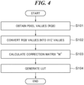
FIG. 4 is a flowchart showing a LUT generation process. -
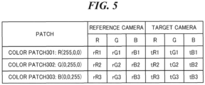
FIG. 5 is a schematic view showing color patch pixel values (RGB values). -
FIG. 6 is a schematic view showing color patch pixel values (XYZ values) corresponding to color patches. -
FIG. 7 is a view showing an example of a correction LUT. -
FIG. 8 is a functional block diagram showing a controller involved in a color difference signal plotting process in a first embodiment. -
FIG. 9 is a view showing an example of color difference signals of the entire captured image displayed on a screen. -
FIG. 10A and FIG. 10B are views showing examples of vector scope images displayed on the screen. -
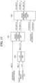
FIG. 11 is a functional block diagram showing a controller involved in a color difference signal plotting process in a second embodiment. -
FIG. 12A, FIG. 12B, and FIG. 12C are views showing examples of vector scope images and a superimposed image displayed on the screen. -
FIG. 13A, FIG. 13B, FIG. 13C, and FIG. 13D are views showing examples of vector scope images, target rectangles, and a superimposed image displayed on the screen. -
FIG. 14A, FIG. 14B, and FIG. 14C are views showing examples of vector scope images corresponding to patches of 20 colors and a vector scope image in which the color difference signals corresponding to some colors are limited to display. - Hereafter, embodiments according to the present invention will be described in detail by referring to the drawings.
-
FIG. 1 is a schematic view showing a configuration of a color adjustment system including a color adjustment apparatus according to a first embodiment of the present invention. The color adjustment system includes acontrol apparatus 102 as a color adjustment apparatus, a firstimage capturing apparatus 100, a secondimage capturing apparatus 101, and adisplay device 103. - The
control apparatus 102 include aCPU 102a, aROM 102b, and aRAM 102c. TheROM 102b stores various programs and values used for control. TheCPU 102a controls the entire system by running the programs stored in theROM 102b. TheRAM 102c provides a work area for theCPU 102a to perform a control program. - The first
image capturing apparatus 100 is a reference camera serving as a reference for performing color matching in a color matching process between the image capturing apparatuses. The secondimage capturing apparatus 101 is a target camera serving as a color matching target (correction target). Each of theimage capturing apparatuses control apparatus 102 via a video line. It should be noted that transmission of the captured image via the video line is not indispensable, and a configuration without the video line can be achieved. For example, the captured image may be transferred via a recording medium such as a memory card, or the captured image may be transmitted and received by wireless communication. - In the color matching process, the
image capturing apparatuses color chart 105 for the color matching. The images captured by theimage capturing apparatuses control apparatus 102. In thecolor chart 105, a plurality of color patches having different colors (for example, threepatches - It should be noted that it is not indispensable to capture the images with the
image capturing apparatuses image capturing apparatuses color chart 105. Also, the positions of the image capturing apparatuses in capturing images may be separated from each other as long as the images of theimage capturing apparatuses color chart 105. - Hereinafter, the images captured by the
image capturing apparatuses control apparatus 102 generates a correction LUT as correction information for color matching based on the reference camera image and the target camera image received from theimage capturing apparatuses control apparatus 102 generates a confirmation image for confirming an effect of the generated correction LUT. The detailed operation of thecontrol apparatus 102 related thereto will be described later. - The
display device 103 displays a UI used when thecontrol apparatus 102 generates the correction LUT and the confirmation image for confirming the effect of the correction LUT. Thedisplay device 103 is connected to thecontrol apparatus 102 via a cable of a general image standard, such as HDMI (registered trademark) or DVI, and displays image information and other additional information on the screen. Specifically, thecontrol apparatus 102 causes thedisplay device 103 to display the reference camera image, the target camera image before applying the correction LUT, the target camera image after applying the correction LUT, and color difference signals (vector scope). - When the target camera images before and after applying the correction LUT are switched and displayed, these images can be easily compared. The images before and after applying the correction LUT may be displayed side by side. However, it is not indispensable to display the images before and after applying of the correction LUT.
- The details of operations of the
control apparatus 102 will now be described. Thecontrol apparatus 102 executes an LUT generation process and a color difference signal plotting process of an input captured image. First, the LUT generation process will be described with reference toFIG. 2 to FIG. 7 . -
FIG. 2 is a functional block diagram showing thecontrol apparatus 102 involved in the LUT generation process. Thecontrol apparatus 102 includes a color-patch-position determination unit 200, a color-patch-pixel-value extraction unit 201, and anLUT generation unit 202 as functional units related to the LUT generation process. - The functions of the color-patch-
position determination unit 200, the color-patch-pixel-value extraction unit 201, and theLUT generation unit 202 are achieved by cooperation of theCPU 102a,ROM 102b,RAM 102c, etc. in thecontrol apparatus 102. The reference camera image IMG_R and the target camera image IMG_T are input to the color-patch-position determination unit 200. -
FIG. 3A and FIG. 3B are views respectively showing examples of the reference camera image IMG_R and the target camera image IMG_T. Each of the camera images IMG_R and IMG_T includes a color chart image corresponding to thecolor chart 105. Images corresponding topatches patch images patch images patches patches - The color-patch-
position determination unit 200 generates color patch position information POSITION_R about the reference camera image IMG_R and color patch position information POSITION_T about the target camera image IMG_T as follows. - First, the color-patch-
position determination unit 200 receives designated positions of thepatch images patch image position determination unit 200 determinesextraction areas extraction areas - Each extraction area is rectangular as an example. It should be noted that the method of designating the positions of the
patch images patches patch images - The color-patch-
position determination unit 200 generates position information POSITION_R indicating theextraction area extraction area value extraction unit 201 receives the images IMG_R and IMG_T from the cameras and receives the position information POSITION_R and POSITION_T from the color-patch-position determination unit 200. - It should be noted that it is not indispensable to receive the designated position of the
patch images patch images - The color-patch-pixel-
value extraction unit 201 extracts RGB pixel values of areas (theextraction areas - The RGB pixel values of the color patches extracted from the reference camera image IMG_R are output as the color patch pixel values PIXEL_VALUE_R in the reference camera image. That is, the color patch pixel values PIXEL_VALUE_R are the RGB pixel values of the
extraction areas extraction areas - An average value of the pixel values in the designated color patch area is extracted as the RGB value. However, the method of extracting a pixel value is not limited to this method. For example, a pixel value at the center of the area may be extracted as the RGB value. When the average value of the pixel values in the area is extracted, a noise resistance becomes higher than the case where the pixel value at the center of the area is extracted as the RGB value although an arithmetic process occurs.
- The color patch pixel values PIXEL_VALUE_R, PIXEL_VALUE_T are input to the
LUT generation unit 202. TheLUT generation unit 202 generates a correction LUT based on the color patch pixel values PIXEL VALUE R and PIXEL_VALUE_T. Here, the correction LUT is used to correct the color patch pixel values PIXEL_VALUE_T so as to match the color patch pixel values PIXEL_VALUE_R. - A process for generating the correction LUT by the
LUT generation unit 202 will be described in detail with reference toFIG. 4. FIG. 4 is a flowchart showing an LUT generation process. This process is achieved by theCPU 102a developing a program stored in theROM 102b to theRAM 102c and executing the program. - In a step S101, the
LUT generation unit 202 obtains the color patch pixel values PIXEL_VALUE_R and PIXEL_VALUE_T from the color-patch-pixel-value extraction unit 201. In a step S102, theLUT generation unit 202 converts the RGB values of the color patch pixel values PIXEL_VALUE_R and PIXEL_VALUE_T into XYZ values. The RGB values are converted into the XYZ values by using the following formula 1, for example.
- The RGB-to-XYZ conversion matrix in the formula 1 can be calculated using, for example, x-y coordinates of the display color gamut of the
display device 103 and an x-y coordinate of a white point. Values obtained by normalizing the RGB values of each color patch are used as RGB values. -
FIG. 5 is a schematic view showing the color patch pixel values (RGB values) corresponding to thepatch images FIG. 6 is a schematic view showing the color patch pixel values (XYZ values) corresponding to thepatch images FIG. 5 are converted into the XYZ values shown inFIG. 6 by using the RGB-to-XYZ conversion matrix (formula 1). - As shown in
FIG. 6 , the RGB values of theextraction areas extraction areas - Next, in a step S103, the
LUT generation unit 202 calculates a correction matrix M for matching the color of the target camera image to the color of the reference camera image. Here, the correction matrix M is a matrix for correcting the XYZ values of the color patch of the target camera image to the XYZ values of the color patch of the reference camera image. The correction matrix M is calculated by the following formula 2 using the calculated arithmetic matrixes R and T.
- The
LUT generation unit 202 generates a correction LUT using the correction matrix M calculated in thestep S 103 and outputs the generated correction LUT in a step S104, and finishes the process shown inFIG. 4 . - Specifically, the
LUT generation unit 202 calculates corrected XYZ values using the converted XYZ values and the correction matrix M in the step S104. Then, theLUT generation unit 202 calculates the corrected RGB values (Out) from the corrected XYZ values using the inverse matrix of the RGB-to-XYZ transformation matrix. The calculated relationship between In and Out of the RGB values is generated as a correctedLUT 106 as 3D-LUT. -
FIG. 7 is a view showing an example of thecorrection LUT 106. The illustrated correction LUT includes 17 × 17 × 17 grid points and stores the corrected RGB values (Out) corresponding to the RGB values (In) of the grid points. It should be noted that the number of the grid points is not limited to the illustrated number. If the number of grid points is increased, the color matching accuracy will increase, but the scale of the process will increase. Conversely, if the number of grid points is made smaller, the scale of process will be smaller, but the color matching accuracy will be reduced. The user may appropriately determine these factors in consideration of cost effectiveness. The correction LUT is input to an LUT application unit 400 (FIG. 8 ) described later. - Although the number of the color patches included in the
color chart 105 is three in this embodiment, the number is not limited to three. It is known that the accuracy increases as the number of colors used for generating the correction LUT increases. Since the calculation time increases as the number of color patches increases, the type and the number of patches of thecolor chart 105 used for the color matching may be selected in consideration of the trade-off between the accuracy and the calculation time. - Although the example in which the correction LUT is generated from two input captured images has been described, a configuration in which a correction LUT generated in advance is read may be employed. In this case, it is necessary to generate in advance a correction LUT that causes the target camera image to approach the reference camera image using the reference camera and the target camera.
- A color difference signal plotting process will now be described by referring to
FIG. 8. FIG. 8 is a functional block diagram showing thecontrol apparatus 102 related to the color difference signal plotting process in the first embodiment. Thecontrol apparatus 102 includes theLUT application unit 400, a color differencesignal conversion unit 401, and a color differencesignal plotting unit 402 as functional units related to the color difference signal plotting process. The functions of theLUT application unit 400, the color differencesignal conversion unit 401, and the color differencesignal plotting unit 402 are achieved by the cooperation of theCPU 102a,ROM 102b, andRAM 102c in thecontrol apparatus 102. - The
LUT application unit 400 as a second obtainment means obtains a target camera image IMG_T (second captured image). TheLUT application unit 400 as a third obtainment means obtains thecorrection LUT 106 generated by the LUT generation unit 202 (FIG. 2 ). As described above, thecorrection LUT 106 to be obtained may be generated in advance and input from the outside. - The
LUT application unit 400 as a correction means applies thecorrection LUT 106 to the target camera image IMG_T to generate a post LUT-application (post color matching) target camera image IMG_T_LUT (third captured image). Then, theLUT application unit 400 outputs the generated target camera image IMG_T_LUT to the color differencesignal conversion unit 401. - The color difference
signal conversion unit 401 as a first obtainment means obtains a reference camera image IMG_R (first captured image). In addition, the color differencesignal conversion unit 401 obtains the post LUT-application target camera image IMG_T_LUT. - The color difference
signal conversion unit 401 as an output means converts the format of the camera images IMG_R, IMG_T_LUT from the RGB format into the YCbCr format using the following formula 3 and outputs them as color difference signals. Here, the RGB-to-YCbCr conversion matrix may consist of values determined in accordance with an input color standard (BT.709 etc.).
- That is, the color difference
signal conversion unit 401 outputs the color difference signals VEC INFO R as the color difference signals of the reference camera image IMG_R and outputs the color difference signals VEC_INFO_T as the color difference signals of the target camera image IMG T LUT. - The color difference
signal plotting unit 402 obtains the color difference signals VECINFOR and VEC INFO T from the color differencesignal conversion unit 401. Further, the color differencesignal plotting unit 402 obtains pieces of position information POSITION_R and POSITION_T. - Here, the pieces of position information POSITION_R and POSITION_T are generated using a technique similar to the generation by the color-patch-position determination unit 200 (
FIG. 2 ) in the LUT generation process. The pieces of position information POSITION_R and POSITION_T shall be designated by the user. Therefore, theextraction areas extraction areas extraction areas - The color difference
signal plotting unit 402 as a generation means generates a vector scope image VEC IMG_R (first image) from the color difference signals VEC_INFO_R based on the position information POSITION_R. The color differencesignal plotting unit 402 also generates a vector scope image VEC_IMG_T (second image) from the color difference signals VEC_INFO_T based on the position information POSITION_T. - The color difference signals VEC_INFO_R and VEC_INFO_T represent the entire captured images. In the meantime, the vector scope image VEC_IMG_R is based only on the color difference signals of the
extraction areas extraction areas - The control apparatus 102 (the color difference signal plotting unit 402) causes the
display device 103 to display the vector scope image VEC_IMG_R and the vector scope image VEC_IMG_T as described latter by referring toFIG. 9 ,FIG. 10A, and FIG. 10B . Specifically, thecontrol apparatus 102 clips the color difference signals of areas outside the extraction areas among the color difference signals VEC_INFO_R and VEC_INFO_T to "0". By performing such a process, only the color difference signals within the extraction areas are plotted as the color difference signals for the captured image, while the color difference signals outside the extraction areas are not plotted. -
FIG. 9 is a view showing an example of displaying color difference signals of the input entire captured image on a screen.FIG. 10A and FIG. 10B are views that respectively show examples in which the vector scope images VEC_IMG_R and VEC_IMG_T are displayed on the screen. - In the images shown in
FIG. 9 ,FIG. 10A, and FIG. 10B , the color difference signals (Cb, Cr) are two-dimensionally plotted on a coordinate system of which a horizontal axis is a Cb axis and a vertical axis is a Cr axis. - As shown in
FIG. 10A and FIG. 10B , the vector scope images VEC_IMG_R and VEC_IMG_T are displayed side-by-side by dividing one screen into two or using two screens. Thus, the colors of the color patches included in thecolor chart 105 can be displayed in a pinpoint manner. Therefore, the color difference signals of each patch color can be compared in the pinpoint manner by comparing the image inFIG. 10A with the image inFIG. 10B , which allows the user to easily check the color coincidence of the colors in the color matching. - As described above, since only the color difference signals of the cut-out areas in the captured images are plotted and displayed on the screen, the color matching accuracy after the color matching can be easily recognized even when the field angles of the two images are different.
- According to this embodiment, the vector scope image VEC_IMG_R is generated based only on the color difference signals in the
extraction areas color chart 105 among the reference camera image IMG_R. In addition, the vector scope image VEC_IMG_T is generated based only on the color difference signals of theextraction areas - It should be noted that the image of color difference signals of the entire captured image (
FIG. 9 ) and the vector scope images (FIG. 10A and FIG. 10B ) may be switched using a display mode switching UI (not shown). For example, when the user selects an "entire mode" for displaying the color difference signals of the entire captured image, the image inFIG. 9 is displayed. And when the user selects a "chart mode" for displaying only the color difference signals in the cut-out areas, the images inFIG. 10A and FIG. 10B are displayed. - It should be noted that the vector scope images VEC_IMG_R and VEC_IMG_T are not necessarily displayed side by side. For example, the vector scope image VEC_IMG_R (
FIG. 10A ) and the vector scope image VEC_IMG_T (FIG. 10B ) may be switched and displayed in response to a user operation. - It should be noted that the pieces of position information POSITION_R and POSITION_T in the color difference signal plotting process may be generated by a method different from that in generating the correction LUT. An extraction area (a cut-out area) may not be a part of each of the
patch images patch images - The
extraction areas extraction areas - In this way, even when the field angle of the color chart image included in the captured image is small, an amount of information for plotting the color difference signals increases, and thus it is possible to generate the color difference signals that are easy to visually recognize. In addition, the same effect can be obtained by a simple method that expands and plots the points when the field angle ratio of the color chart image is smaller than a certain value.
- A second embodiment of the present invention will now be described. In the first embodiment, the example in which the color difference signals of only the extraction area (cut-out area) are plotted and displayed for each of the reference camera image and the target camera image has been described. In the meantime, in the second embodiment, an example in which the color difference signals of only the extraction area of both the reference camera image and the target camera image are displayed in an overlapping manner will be described.
- Thus, in this embodiment, the color difference signal plotting process is different from the first embodiment and the LUT generation process is the same as in the first embodiment.
-
FIG. 11 is a functional block diagram showing acontrol apparatus 102 involved in a color difference signal plotting process in the second embodiment. Thecontrol apparatus 102 includes anLUT application unit 500, a color differencesignal conversion unit 501, and a color differencesignal plotting unit 502 as functional units related to the color difference signal plotting process. The basic functions of theLUT application unit 500, the color differencesignal conversion unit 501, and the color differencesignal plotting unit 502 are the same as those of theLUT application unit 400, the color differencesignal conversion unit 401, and the color differencesignal plotting unit 402 shown inFIG. 8 , respectively. However, the color differencesignal plotting unit 502 is different from the color differencesignal plotting unit 402, further generates a superimposed image VEC_IMG_RT. It should be noted that it is not indispensable to display the vector scope images VEC_IMG_R and VEC_IMG_T described in the first embodiment. - The superimposed image VEC_IMG_RT is generated by superimposing the vector scope image VEC_IMG_R and the vector scope image VEC_IMG_T. The
control apparatus 102 displays the superimposed image VEC_IMG_RT on the same screen of thedisplay device 103. Display examples thereof will be described with reference toFIG. 12A, FIG. 12B, and FIG. 12C . -
FIG. 12A and FIG. 12B respectively show examples of the vector scope images VEC_IMG_R and VEC_IMG_T displayed on the screen.FIG. 12C is a view showing an example of the superimposed image VEC_IMG_RT displayed on the screen. - In the first embodiment, the number of the color patches included in the
color chart 105 is three (three colors). InFIG. 12A, FIG. 12B, and FIG. 12C , the number of the color patches is twenty (twenty colors). As described above, it is not indispensable to display the screens shown inFIG. 12A and FIG. 12B . - The color difference
signal plotting unit 502 plots the vector scope images VEC_IMG_R and VEC_IMG_T in mutually different colors. For example, the color differencesignal plotting unit 502 plots the vector scope image VEC_IMG_R in white and the vector scope image VEC_IMG_T in black. The colors are not limited thereto. - As shown in
FIG. 12C , the color differencesignal plotting unit 502 plots the vector scope image VEC_IMG_R (an upper hierarchical layer) so as to be superimposed on the vector scope image VEC_IMG_T. Therefore, only the vector scope image VEC IMG_R is visually recognized in a portion where display positions of both color difference signals are mutually overlapped with respect to colors having a small color shift. In the meantime, since display positions of color difference signals of two colors having a large color shift are separated from each other, the shifted color is conspicuous, and the shift of the color difference signals can be recognized at a glance. The example inFIG. 12C shows that large shifts remain in a red (R) direction, a yellow (Yl) direction, and a cyan (Cy) direction. It does not matter which one of the vector scope images VEC_IMG_R and VEC_IMG_T is arranged in the upper hierarchical layer. - In a case where the display colors of the vector scope images VEC_IMG_R and VEC_IMG_T are green and red, respectively, only a portion where the colors are shifted is displayed in red. Therefore, it is also possible to match with the sense generally used for warning (red indicates warning).
- According to this embodiment, the superimposed image VEC_IMG_RT in which vector scope images VEC_IMG_R and VEC_IMG_T are superimposed is displayed. Therefore, the same effect as that of the first embodiment can be achieved with respect to ease of visual recognition of the color matching accuracy.
- In addition, since the vector scope images VEC_IMG_R and VEC_IMG_T are plotted in colors different from each other, the color matching accuracy can be understood more easily.
- It should be noted that the color difference
signal plotting unit 502 may determine plotting colors of the vector scope images VEC_IMG_R and VEC_IMG_T in accordance with the coincidence of these vector scope images for each color of a patch. - For example, the color difference
signal plotting unit 502 uniformly determines the plotting color of the vector scope image VEC_IMG_R to be a predetermined color (e.g., white). The color differencesignal plotting unit 502 determines the plotting color of the vector scope image VEC_IMG_T to be green for a color whose coincidence between the vector scope images VEC_IMG_R and VEC_IMG_T is higher than a predetermined value among the colors of the patches. The color differencesignal plotting unit 502 determines the plotting color of the vector scope image VEC_IMG_T to be red for a color whose coincidence is lower than the predetermined value. - In this way, the color coincidence can be recognized at a glance. The color coincidence may be calculated using the reference camera image and target camera image according to a general indicator (for example, CIE2000). It should be noted that the plotting color of the vector scope image VEC IMG_R may also be determined corresponding to the color coincidence.
- In addition to this, an area in which the color difference signals overlap between the vector scope images VEC_IMG_R and VEC_IMG_T may be plotted and displayed in a color different from the plotting colors of the vector scope images VEC_IMG_R and VEC_IMG_T. For example, in the case where the plotting colors of the vector scope images VEC_IMG_R and VEC_IMG_T are green and red, respectively, the area in which the color difference signals overlap may be displayed in yellow. In this way, it is possible to recognize a direction of the color shift at a glance.
- In addition, the color difference
signal plotting unit 502 may generate another superimposed image in which the color difference signals VEC INFO R of the reference camera image IMG_R and the color difference signals of the target camera image IMG_T before application of the correction LUT are superimposed. Then, thecontrol apparatus 102 may switch and display the superimposed image VEC_IMG_RT and the other superimposed image. For example, when both the superimposed images are switched and displayed in response to a user instruction, the user can easily confirm the matching states of the colors before and after applying the correction LUT at a glance. - A third embodiment of the present invention will now be described. In the third embodiment, a superimposed image in which an image indicating the target position of the color difference signals VEC_INFO_R for each color is superimposed on the color difference signals VEC_INFO_R is generated. Other configurations in this embodiment are the same as those in the second embodiment.
-
FIG. 13A and FIG. 13B respectively show examples of the vector scope images VEC_IMG_R and VEC_IMG_T displayed on the screen.FIG. 13C is a view showing an example in which target rectangles K1 are displayed on a screen.FIG. 13D is a view showing an example a superimposed image in which the target rectangles K1 are superimposed on the vector scope image VEC_IMG_T displayed on the screen. - The screens shown in
FIG. 13A and FIG. 13B are similar to those shown inFIG. 12A and FIG. 12B . It is not indispensable to display the screens shown inFIG. 13A, FIG. 13B, and FIG. 13C . - Here, a target rectangle K1 is an example of an image indicating a target position of the color difference signals VEC_INFO_R for each color. To be specific, the target rectangle K1 is a frame indicating a predetermined area based on each target position. It should be noted that the predetermined area may be a fixed area. The target rectangles K1 may be provided corresponding to all colors. However, only the target rectangles corresponding to some predetermined colors are displayed in this embodiment. For example, the target rectangles K1 indicating target positions corresponding to red (R), green (G), blue (B), cyan (Cy), magenta (Mg), and yellow (Yl) among the patch colors are displayed.
- A superimposed image shown in
FIG. 13D is generated by superimposing the image shown inFIG. 13C on the image shown inFIG. 13B . As understood fromFIG. 13D , the larger the color shift is, the more distant the vector scope image VEC_IMG_T from the target rectangle K1 is. Therefore, the shift of the color difference signals can be visually recognized at a glance. In the example shown inFIG. 13D , large shifts occur in the red (R) direction, the yellow (Yl) direction, and the cyan (Cy) direction. - According to this embodiment, the superimposed image in which the target rectangles K1, which are images indicating the target positions of the color difference signals VEC_INFO_R for each color, are superimposed on the color difference signals VEC_INFO_R is generated and displayed. Therefore, the same effect as that of the first embodiment can be achieved with respect to ease of visual recognition of the color matching accuracy. In particular, the shift of the color difference signals can be visually recognized at a glance.
- Although the target rectangle K1 is a rectangle, the shape of the image indicating the target position is not limited to a rectangle as long as the shape allows the target position to be visually recognized. For example, an arbitrary figure such as a circle, a triangle, or a rhombus, may be employed. In addition, it is not indispensable that the image indicating the target position is based on the center position.
- The area of the target rectangle K1 (the area of the image indicating the target position) may be determined based on a limit area in which a color difference can be recognized by human eyes. For example, the image size of the target rectangle K1 can be determined in accordance with the visual recognition capability of human eyes. Specifically, an area in which a person cannot visually recognize a color difference may be determined as the area of the image with respect to the median coordinate of the target position. In this way, the user can confirm the allowable color shift at a glance. The area in which a person cannot visually recognize the color difference can be determined based on the CIE2000.
- Although the example in which the target positions are displayed for six colors of red (R), green (G), blue (B), cyan (Cy), magenta (Mg), and yellow (Yl) has been described, other display methods may be employed. For example, color pairs of the vector scope image VEC_IMG_T and the target rectangles K1 may be displayed in each of four quadrants divided by the Cb and Cr axes to be plotted. This makes it easy to visually recognize a shift from the target position without overlapping the colors. Further, when the user switches the display while designating the color to be checked, the user can check the shifts from the target positions for all the colors.
- A fourth embodiment of the present invention will now be described. In the fourth embodiment, display of color difference signals corresponding to a part of colors among a plurality of patch colors is limited (not displayed). Other configurations are the same as those of the first embodiment.
-
FIG. 14A and FIG. 14B are schematic views showing the vector scope image VEC_IMG_R corresponding to the patches of 20 colors. InFIG. 14B , color difference signals corresponding to colors to be displayed among the patches of 20 colors are shown in white, and color difference signals not to be displayed among the patches of 20 colors are shown in black. -
FIG. 14C is a view showing an example in which the vector scope image VEC IMG_R in which display of color difference signals corresponding to some colors is limited is displayed on the screen. AlthoughFIG. 14A, FIG. 14B, and FIG. 14C show the generation and display of the vector scope image VEC_IMG_R as a representative, the vector scope image VEC_IMG_T is also subjected similarly. - When the number of the patch colors is large and the color difference signals corresponding to the patches are close to each other, the plotting areas are likely to overlap with each other, and it may be difficult to distinguish the correspondence of colors. Therefore, in such a case, the number of colors for plotting color difference signals is limited.
- When the number of colors is limited so as to reduce 8 colors (black circles) and display 12 colors (white circles) out of the 20 colors of the patches shown in
FIG. 14B , the screen shown inFIG. 14C is obtained. By performing such a process, it becomes easy to grasp the color shifts with respect to the important colors. Similar to the vector scope image VEC IMG_R shown inFIG. 14C , the vector scope image VEC_IMG_T is also generated with the limited number of colors (not shown). - The following criteria for limiting the number of colors may be considered. First, when there are a plurality of colors of which the color difference signals are closer than a threshold among the colors of the patches, the color difference
signal plotting unit 402 excludes at least one color among the plurality of colors and generates the vector scope images VEC_IMG_R and VEC IMG T. - For example, when there are a plurality of colors of which the color difference signals are closer than the threshold among the colors of the patches, the color difference
signal plotting unit 402 may generate the vector scope images VEC_IMG_R and VEC_IMG_T without excluding the color having the highest saturation. That is, when the vector scope image is generated, the saturation may be prioritized, and the color difference signals of the color having the lowest saturation may be excluded, or the color difference signals of the colors other than the color having the highest saturation may be excluded. - Alternatively, when there are a plurality of colors of which the color difference signals are closer than the threshold among the colors of the patches, the color difference
signal plotting unit 402 may generate the vector scope image VEC_IMG_R and the VEC_IMG_T without excluding the color having the largest color shift among the colors of the patches. That is, when generating the vector scope image, the color shift may be prioritized, and the color difference signals of the color with the lowest color shift may be excluded, or the color difference signals of colors other than the color with the highest color shift may be excluded. - Alternatively, a color in which the color difference signals are close may be replaced by a single color. Alternatively, the number of colors in a portion selected by the user may be limited.
- In each of the above embodiments, the vector scope images are exemplified as the first image and the second image based only on color difference signals. However, the present invention is not limited thereto. For example, waveform images may be used.
- According to this embodiment, the same effect as that of the first embodiment can be achieved with respect to ease of visual recognition of the color matching accuracy. In particular, since the color difference signals corresponding to some of the colors of the plurality of patch colors are not displayed, the color matching accuracy can be easier to recognize.
- Although the present invention has been described in detail on the basis of the suitable embodiments, the present invention is not limited to these specific embodiments, and various configurations that do not deviate from the scope of the present invention are also included in the present invention. Some of the above-described embodiments may be appropriately combined.
- Embodiment(s) of the present invention can also be realized by a computer of a system or apparatus that reads out and executes computer executable instructions (e.g., one or more programs) recorded on a storage medium (which may also be referred to more fully as a 'non-transitory computer-readable storage medium') to perform the functions of one or more of the above-described embodiment(s) and/or that includes one or more circuits (e.g., application specific integrated circuit (ASIC)) for performing the functions of one or more of the above-described embodiment(s), and by a method performed by the computer of the system or apparatus by, for example, reading out and executing the computer executable instructions from the storage medium to perform the functions of one or more of the above-described embodiment(s) and/or controlling the one or more circuits to perform the functions of one or more of the above-described embodiment(s). The computer may comprise one or more processors (e.g., central processing unit (CPU), micro processing unit (MPU)) and may include a network of separate computers or separate processors to read out and execute the computer executable instructions. The computer executable instructions may be provided to the computer, for example, from a network or the storage medium. The storage medium may include, for example, one or more of a hard disk, a random-access memory (RAM), a read only memory (ROM), a storage of distributed computing systems, an optical disk (such as a compact disc (CD), digital versatile disc (DVD), or Blu-ray Disc (BD)™), a flash memory device, a memory card, and the like.
- While the present invention has been described with reference to exemplary embodiments, it is to be understood that the invention is not limited to the disclosed exemplary embodiments. The scope of the following claims is to be accorded the broadest interpretation so as to encompass all such modifications and equivalent structures and functions.
- PROBLEM TO BE SOLVED: To display color matching accuracy in a visually intelligible manner.
- SOLUTION: A color adjustment apparatus (102) includes means for obtaining a first captured image by capturing a color chart (105) including patches (301C, 302C, 303C) with a reference camera (100), means (400) for obtaining a second captured image by capturing the color chart with a target camera (101), for obtaining information for color matching, and for generating a third captured image by applying the information to the second captured image, means (401) for outputting color difference signals of the first and third captured images, and means (402) for generating a first image based on color difference signals in areas corresponding to the patches among the color difference signals of the first captured image and a second image based on color difference signals in the areas among the color difference signals of the third captured image.
Claims (17)
- A color adjustment apparatus (102) comprising:a first obtainment means (401) for obtaining a first captured image by capturing a color chart (105) for color matching including patches (301C, 302C, and 303C) with a first image capturing apparatus (100) serving as a reference;a second obtainment means (400) for obtaining a second captured image by capturing the color chart with a second image capturing apparatus (101) serving as a correction target;a third obtainment means (400) for obtaining correction information for the color matching;a correction means (400) for generating a third captured image by applying the correction information obtained by the third obtainment means to the second captured image obtained by the second obtainment means;an output means (401) for outputting color difference signals of the first captured image obtained by the first obtainment means and color difference signals of the third captured image generated by the correction means; anda generation means (402) for generating a first image based on color difference signals in areas corresponding to the patches in the color chart among the color difference signals of the first captured image output by the output means and a second image based on color difference signals in areas corresponding to the patches among the color difference signals of the third captured image output by the output means.
- The color adjustment apparatus according to claim 1, wherein the generation means generates a superimposed image in which the first image and the second image are superimposed.
- The color adjustment apparatus according to claim 2, wherein the generation means generates the superimposed image by superimposing the first image on the second image.
- The color adjustment apparatus according to claim 2 or 3, wherein the generation means plots the first image and the second image in different colors.
- The color adjustment apparatus according to claim 2 or 3, wherein the generation means determines colors for plotting the first image and the second image in accordance with coincidence of the first image and the second image for each of colors of the patches.
- The color adjustment apparatus according to claim 1, wherein the generation means generates a superimposed image in which an image showing a target position of the first image for each color is superimposed on the second image.
- The color adjustment apparatus according to claim 6, wherein the image showing the target position is an image showing a predetermined area based on the target position.
- The color adjustment apparatus according to claim 1, wherein the generation means generates, in a case where there are a plurality of colors whose color difference signals are closer than a threshold among the colors of the patches, the first image and the second image while excluding at least one of the plurality of colors.
- The color adjustment apparatus according to claim 8, wherein the generation means generates the first image and the second image without excluding a color having the highest saturation in the case where there are the plurality of colors whose color difference signals are closer than the threshold among the colors of the patches.
- The color adjustment apparatus according to claim 8, wherein the generation means generates the first image and the second image without excluding a color having the largest color shift among the colors of the patches in the case where there are the plurality of colors having color difference signals are closer than the threshold among the colors of the patches.
- The color adjustment apparatus according to claim 1, wherein the generation means displays the first image and the second image on a screen.
- The color adjustment apparatus according to any one of claims 1 through 11, wherein the correction information is generated based on an image obtained by capturing the color chart by the first image capturing apparatus and an image obtained by capturing the color chart by the second image capturing apparatus.
- The color adjustment apparatus according to any one of claims 1 through 12, wherein the correction information is a lookup table for bringing a color of an image captured by the second image capturing apparatus closer to a color of an image captured by the first image capturing apparatus.
- The color adjustment apparatus according to any one of claims 1 through 13, wherein areas corresponding to the patches in generating the first image and areas corresponding to the patches in generating the second image are determined by a user.
- The color adjustment apparatus according to any one of claims 1 through 14, wherein areas corresponding to the patches in generating the first image are determined based on a field angle ratio of the color chart included in the first captured image, and areas corresponding to the patches in generating the second image are determined based on a field angle ratio of the color chart included in the second captured image.
- A color adjustment method comprising:a first obtainment step of obtaining a first captured image by capturing a color chart (105) for color matching including patches (301C, 302C, and 303C) with a first image capturing apparatus (100) serving as a reference;a second obtainment step of obtaining a second captured image by capturing the color chart with a second image capturing apparatus (101) serving as a correction target;a third obtainment step of obtaining correction information for the color matching;a correction step of generating a third captured image by applying the correction information obtained in the third obtainment step to the second captured image obtained in the second obtainment step;an output step of outputting color difference signals of the first captured image obtained in the first obtainment step and color difference signals of the third captured image generated in the correction step; anda generation step of generating a first image based on color difference signals in areas corresponding to the patches in the color chart among the color difference signals of the first captured image output in the output step and a second image based on color difference signals in areas corresponding to the patches among the color difference signals of the third captured image output in the output step.
- A computer-executable program for causing a computer to function as each means of the color adjustment apparatus according to any one of claims 1 through 15.
Applications Claiming Priority (1)
| Application Number | Priority Date | Filing Date | Title |
|---|---|---|---|
| JP2022101219A JP2024002174A (en) | 2022-06-23 | 2022-06-23 | Color adjustment device and method, program |
Publications (2)
| Publication Number | Publication Date |
|---|---|
| EP4297391A1 true EP4297391A1 (en) | 2023-12-27 |
| EP4297391B1 EP4297391B1 (en) | 2026-04-15 |
Family
ID=86646526
Family Applications (1)
| Application Number | Title | Priority Date | Filing Date |
|---|---|---|---|
| EP23176402.8A Active EP4297391B1 (en) | 2022-06-23 | 2023-05-31 | Color adjustment apparatus, color adjustment method, and program |
Country Status (4)
| Country | Link |
|---|---|
| US (1) | US12333764B2 (en) |
| EP (1) | EP4297391B1 (en) |
| JP (1) | JP2024002174A (en) |
| CN (1) | CN117294825A (en) |
Citations (3)
| Publication number | Priority date | Publication date | Assignee | Title |
|---|---|---|---|---|
| US20080192120A1 (en) * | 2006-02-14 | 2008-08-14 | Corley Ferrand D E | Security camera image correction system and method |
| JP2011217091A (en) | 2010-03-31 | 2011-10-27 | Canon Inc | Imaging apparatus and method for controlling the imaging apparatus |
| US20150103093A1 (en) * | 2013-10-14 | 2015-04-16 | Apple Inc. | System and Method for Displaying Image Data on a Vectorscope |
Family Cites Families (5)
| Publication number | Priority date | Publication date | Assignee | Title |
|---|---|---|---|---|
| JPH099270A (en) * | 1995-06-23 | 1997-01-10 | Sony Corp | Video camera and video camera device |
| US20030081118A1 (en) * | 2001-10-29 | 2003-05-01 | Cirulli Robert J. | Calibration of a telecine transfer device for a best light video setup |
| KR100962797B1 (en) * | 2008-11-04 | 2010-06-10 | 신태은 | Camera setting method and system using a central management server. |
| US11030778B2 (en) * | 2014-03-31 | 2021-06-08 | Healthy.Io Ltd. | Methods and apparatus for enhancing color vision and quantifying color interpretation |
| KR20200044198A (en) * | 2018-10-10 | 2020-04-29 | (주)필링크아이 | Method for evaluating fashion style using deep learning technology and system therefor |
-
2022
- 2022-06-23 JP JP2022101219A patent/JP2024002174A/en active Pending
-
2023
- 2023-05-25 US US18/324,100 patent/US12333764B2/en active Active
- 2023-05-31 EP EP23176402.8A patent/EP4297391B1/en active Active
- 2023-06-21 CN CN202310743000.XA patent/CN117294825A/en active Pending
Patent Citations (3)
| Publication number | Priority date | Publication date | Assignee | Title |
|---|---|---|---|---|
| US20080192120A1 (en) * | 2006-02-14 | 2008-08-14 | Corley Ferrand D E | Security camera image correction system and method |
| JP2011217091A (en) | 2010-03-31 | 2011-10-27 | Canon Inc | Imaging apparatus and method for controlling the imaging apparatus |
| US20150103093A1 (en) * | 2013-10-14 | 2015-04-16 | Apple Inc. | System and Method for Displaying Image Data on a Vectorscope |
Also Published As
| Publication number | Publication date |
|---|---|
| US12333764B2 (en) | 2025-06-17 |
| JP2024002174A (en) | 2024-01-11 |
| EP4297391B1 (en) | 2026-04-15 |
| US20230419548A1 (en) | 2023-12-28 |
| CN117294825A (en) | 2023-12-26 |
Similar Documents
| Publication | Publication Date | Title |
|---|---|---|
| US11422356B2 (en) | Information processing apparatus, imaging control method, program, digital microscope system, display control apparatus, display control method, and program including detection of a failure requiring reimaging | |
| US8422773B2 (en) | Image zone detecting using color gradation levels, method, apparatus and computer readable medium | |
| EP2068569A1 (en) | Method of and apparatus for detecting and adjusting colour values of skin tone pixels | |
| WO2014199564A1 (en) | Information processing device, imaging device, information processing method, and program | |
| US9794538B2 (en) | Color adjustment apparatus, image display apparatus, and color adjustment method | |
| EP2804369A1 (en) | Image processing method, image processing apparatus, and image processing program | |
| EP2742681A1 (en) | Image processing apparatus and control method therefor | |
| KR101931769B1 (en) | Image correction method and apparatus for color vision deficiency | |
| EP1909484B1 (en) | Image processing device, image processing program, and image processing method | |
| JP7599966B2 (en) | Image processing device, image processing method, and program | |
| CN114466181A (en) | Video anomaly detection method, device, equipment and system | |
| EP4297391A1 (en) | Color adjustment apparatus, color adjustment method, and program | |
| US12394394B2 (en) | Display control apparatus used for color matching between reference image pickup apparatus and adjustment image pickup apparatus, control method therefor, and storage medium storing control program therefor | |
| US20180276458A1 (en) | Information processing device, method and storage medium | |
| JP2012042804A (en) | Image processing apparatus and method | |
| CN104737222B (en) | Display device and method for displaying image | |
| JP2009278258A (en) | Image processor, image processing method, program, and recording medium | |
| JP2013210887A (en) | Image processing apparatus and control method therefor | |
| JP2008301238A (en) | Monitoring area setting apparatus and monitoring area setting method for video monitoring system | |
| EP2852165B1 (en) | Method for displaying marker | |
| JP4519778B2 (en) | Orthogonal gamut display method | |
| US12506861B2 (en) | Color reference pattern for chrominance evaluation in images | |
| JP6577766B2 (en) | Image processing device | |
| JP4586963B2 (en) | Automatic pupil correction method | |
| JP2005128774A (en) | Image region extraction apparatus and method |
Legal Events
| Date | Code | Title | Description |
|---|---|---|---|
| PUAI | Public reference made under article 153(3) epc to a published international application that has entered the european phase |
Free format text: ORIGINAL CODE: 0009012 |
|
| STAA | Information on the status of an ep patent application or granted ep patent |
Free format text: STATUS: THE APPLICATION HAS BEEN PUBLISHED |
|
| AK | Designated contracting states |
Kind code of ref document: A1 Designated state(s): AL AT BE BG CH CY CZ DE DK EE ES FI FR GB GR HR HU IE IS IT LI LT LU LV MC ME MK MT NL NO PL PT RO RS SE SI SK SM TR |
|
| STAA | Information on the status of an ep patent application or granted ep patent |
Free format text: STATUS: REQUEST FOR EXAMINATION WAS MADE |
|
| 17P | Request for examination filed |
Effective date: 20240627 |
|
| RBV | Designated contracting states (corrected) |
Designated state(s): AL AT BE BG CH CY CZ DE DK EE ES FI FR GB GR HR HU IE IS IT LI LT LU LV MC ME MK MT NL NO PL PT RO RS SE SI SK SM TR |
|
| GRAP | Despatch of communication of intention to grant a patent |
Free format text: ORIGINAL CODE: EPIDOSNIGR1 |
|
| STAA | Information on the status of an ep patent application or granted ep patent |
Free format text: STATUS: GRANT OF PATENT IS INTENDED |
|
| RIC1 | Information provided on ipc code assigned before grant |
Ipc: H04N 1/60 20060101AFI20251105BHEP Ipc: G06T 11/00 20060101ALN20251105BHEP |
|
| INTG | Intention to grant announced |
Effective date: 20251118 |
|
| GRAS | Grant fee paid |
Free format text: ORIGINAL CODE: EPIDOSNIGR3 |
|
| GRAA | (expected) grant |
Free format text: ORIGINAL CODE: 0009210 |
|
| STAA | Information on the status of an ep patent application or granted ep patent |
Free format text: STATUS: THE PATENT HAS BEEN GRANTED |
|
| AK | Designated contracting states |
Kind code of ref document: B1 Designated state(s): AL AT BE BG CH CY CZ DE DK EE ES FI FR GB GR HR HU IE IS IT LI LT LU LV MC ME MK MT NL NO PL PT RO RS SE SI SK SM TR |
|
| REG | Reference to a national code |
Ref country code: CH Ref legal event code: F10 Free format text: ST27 STATUS EVENT CODE: U-0-0-F10-F00 (AS PROVIDED BY THE NATIONAL OFFICE) Effective date: 20260415 |