EP4297231A1 - Electricity storage system and control device - Google Patents
Electricity storage system and control device Download PDFInfo
- Publication number
- EP4297231A1 EP4297231A1 EP21926492.6A EP21926492A EP4297231A1 EP 4297231 A1 EP4297231 A1 EP 4297231A1 EP 21926492 A EP21926492 A EP 21926492A EP 4297231 A1 EP4297231 A1 EP 4297231A1
- Authority
- EP
- European Patent Office
- Prior art keywords
- power
- power conversion
- conversion devices
- devices
- determination part
- Prior art date
- Legal status (The legal status is an assumption and is not a legal conclusion. Google has not performed a legal analysis and makes no representation as to the accuracy of the status listed.)
- Pending
Links
Images

Classifications
-
- H—ELECTRICITY
- H02—GENERATION; CONVERSION OR DISTRIBUTION OF ELECTRIC POWER
- H02J—ELECTRIC POWER NETWORKS; CIRCUIT ARRANGEMENTS OR SYSTEMS FOR SUPPLYING OR DISTRIBUTING ELECTRIC POWER; SYSTEMS FOR STORING ELECTRIC ENERGY
- H02J3/00—Circuit arrangements for AC mains or AC distribution networks
- H02J3/38—Arrangements for feeding a single network from two or more generators or sources in parallel; Arrangements for feeding already energised networks from additional generators or sources in parallel
-
- H—ELECTRICITY
- H02—GENERATION; CONVERSION OR DISTRIBUTION OF ELECTRIC POWER
- H02J—ELECTRIC POWER NETWORKS; CIRCUIT ARRANGEMENTS OR SYSTEMS FOR SUPPLYING OR DISTRIBUTING ELECTRIC POWER; SYSTEMS FOR STORING ELECTRIC ENERGY
- H02J3/00—Circuit arrangements for AC mains or AC distribution networks
- H02J3/28—Arrangements for balancing of the load in networks by storage of energy
- H02J3/32—Arrangements for balancing of the load in networks by storage of energy using batteries or super capacitors with converting means
-
- H—ELECTRICITY
- H02—GENERATION; CONVERSION OR DISTRIBUTION OF ELECTRIC POWER
- H02J—ELECTRIC POWER NETWORKS; CIRCUIT ARRANGEMENTS OR SYSTEMS FOR SUPPLYING OR DISTRIBUTING ELECTRIC POWER; SYSTEMS FOR STORING ELECTRIC ENERGY
- H02J3/00—Circuit arrangements for AC mains or AC distribution networks
- H02J3/12—Arrangements for adjusting voltage in AC networks by changing a characteristic of the network load
- H02J3/16—Arrangements for adjusting voltage in AC networks by changing a characteristic of the network load by adjustment of reactive power
-
- H—ELECTRICITY
- H02—GENERATION; CONVERSION OR DISTRIBUTION OF ELECTRIC POWER
- H02J—ELECTRIC POWER NETWORKS; CIRCUIT ARRANGEMENTS OR SYSTEMS FOR SUPPLYING OR DISTRIBUTING ELECTRIC POWER; SYSTEMS FOR STORING ELECTRIC ENERGY
- H02J3/00—Circuit arrangements for AC mains or AC distribution networks
- H02J3/38—Arrangements for feeding a single network from two or more generators or sources in parallel; Arrangements for feeding already energised networks from additional generators or sources in parallel
- H02J3/381—Dispersed generators
-
- H—ELECTRICITY
- H02—GENERATION; CONVERSION OR DISTRIBUTION OF ELECTRIC POWER
- H02J—ELECTRIC POWER NETWORKS; CIRCUIT ARRANGEMENTS OR SYSTEMS FOR SUPPLYING OR DISTRIBUTING ELECTRIC POWER; SYSTEMS FOR STORING ELECTRIC ENERGY
- H02J7/00—Circuit arrangements for charging or discharging batteries or for supplying loads from batteries
-
- H—ELECTRICITY
- H02—GENERATION; CONVERSION OR DISTRIBUTION OF ELECTRIC POWER
- H02J—ELECTRIC POWER NETWORKS; CIRCUIT ARRANGEMENTS OR SYSTEMS FOR SUPPLYING OR DISTRIBUTING ELECTRIC POWER; SYSTEMS FOR STORING ELECTRIC ENERGY
- H02J2207/00—Details of circuit arrangements for charging or discharging batteries or supplying loads from batteries
- H02J2207/20—Charging or discharging characterised by the power electronics converter
-
- H—ELECTRICITY
- H02—GENERATION; CONVERSION OR DISTRIBUTION OF ELECTRIC POWER
- H02J—ELECTRIC POWER NETWORKS; CIRCUIT ARRANGEMENTS OR SYSTEMS FOR SUPPLYING OR DISTRIBUTING ELECTRIC POWER; SYSTEMS FOR STORING ELECTRIC ENERGY
- H02J7/00—Circuit arrangements for charging or discharging batteries or for supplying loads from batteries
- H02J7/80—Circuit arrangements for charging or discharging batteries or for supplying loads from batteries including monitoring or indicating arrangements
- H02J7/82—Control of state of charge [SOC]
Definitions
- a power storage system and a control device are provided in which the power loss can be suppressed.
- the power storage system 2 further includes, for example, multiple transformers 12 and a transformer 14.
- the multiple transformers 12 are provided to correspond respectively to the multiple power conversion devices 6.
- the multiple power conversion devices 6 are connected to the multiple transformers 12.
- the multiple transformers 12 are connected to the transformer 14.
- the transformer 14 is connected to a power system PS.
- the multiple power conversion devices 6 are connected with the power system PS that is the load via the transformers 12 and 14, etc.
- a circuit breaker, more transformers, etc., may be located between the power conversion devices 6 and the power system PS.
- the configuration between the power system PS and the power conversion devices 6 may be any configuration that can connect the power conversion devices 6 to the power system PS.
- the power of the power system PS (the load) is AC power.
- the power of the power system PS is, for example, three-phase AC power.
- the power of the power system PS (the load) is not limited to AC power and may be DC power, etc.
- the multiple power conversion devices 6 supply the power to the power system PS based on the DC power stored in the multiple power storage devices 4 and charge the multiple power storage devices 4 based on the power of the power system PS side. Thereby, for example, the power storage system 2 suppresses the frequency fluctuation of the power system PS.
- the power storage system 2 further includes, for example, a measurement device 16.
- the measurement device 16 detects the active power value, the reactive power value, and the voltage value of the connection point between the power system PS and the multiple power conversion devices 6 and inputs the active power value, the reactive power value, and the voltage value that are detected to the control device 10.
- FIG. 2 is a block diagram schematically illustrating the control device according to the embodiment.
- the number determination part 22 calculates a number D2 of the power conversion devices 6 necessary to output the reactive power by using the following Formula (2).
- D 2 round 1 + B 2 ⁇ Aq S 2
- Aq is the total value of the reactive power determined by the output value determination part 20.
- S2 is the rated capacity of the reactive power per one of the multiple power conversion devices 6.
- B2 is the output margin of the reactive power of the multiple power conversion devices 6. Any value between 0 to 1 (p. u.) is set as the output margin B2.
- round is the roundup function.
- the number determination part 22 calculates the number D2 as an integer by rounding up digits to the right of the decimal point.
- the method for calculating the numbers D1 and D2 is not always limited to that described above.
- the output margins B1 and B2 are set to 1 (p. u.) when the power conversion device 6 is to be operated at the rated capacity, and the output margins B1 and B2 are set to any value less than 1 (p. u.) when the output of the power conversion device 6 is to be less than the rated capacity.
- the output margins B1 and B2 may not always be set.
- the method for determining the number by the number determination part 22 may be any determination method based on at least the total value of the active power and the total value of the reactive power determined by the output value determination part 20.
- the conversion device determination part 24 determines prescribed power conversion devices 6 among the multiple power conversion devices 6 of the number determined by the number determination part 22 as the power conversion devices 6 to which the operation command is to be transmitted.
- the conversion device determination part 24 includes, for example, a priority list 30 representing the priorities of the multiple power conversion devices 6.
- the conversion device determination part 24 determines the power conversion devices 6 among the multiple power conversion devices 6 in descending order of the priorities of the priority list 30 of the number determined by the number determination part 22 as the power conversion devices 6 to which the operation command is to be transmitted.
- the command transmitting part 26 transmits a standby command to the remaining power conversion devices 6 among the multiple power conversion devices 6 to which the operation command is not to be transmitted.
- the standby command is a command that stops the operation of the power conversion device 6.
- the standby command is, for example, a command that switches the multiple switching elements of the power conversion device 6 to the off-state.
- the standby command also may be called a gate block command, etc.
- the circuit breaker that corresponds to the power conversion devices 6 to which the standby command is to be transmitted is left in the on-state when the command transmitting part 26 transmits the standby command.
- the command transmitting part 26 transmits the standby command
- the power conversion device 6 is left in the state of being connected to the power storage device 4 and the power system PS; and only the operation of the power conversion device 6 is stopped by the transmission of the standby command.
- the standby command is, for example, a command that stops the operation of the power conversion device 6 while allowing the power conversion device 6 to be operated immediately.
- the control device 10 operates every prescribed control period such as 100 ms, etc. For example, for each control period, the control device 10 determines the total value of the active power and the total value of the reactive power output from the multiple power conversion devices 6 in the output value determination part 20, determines the number of the power conversion devices 6 to which the operation command is to be transmitted in the number determination part 22, determines the power conversion devices 6 to which the operation command is to be transmitted in the conversion device determination part 24, and transmits the operation command or the standby command from the command transmitting part 26 to the multiple power conversion devices 6. Thereby, the control device 10 controls the operations of the multiple power conversion devices 6 every prescribed control period.
- the priority list 30 is, for example, table data in which the device numbers and charge amounts corresponding to the multiple power conversion devices 6 are arranged in descending order of the priorities.
- the charge amounts of the multiple power storage devices 4 change according to the operations of the multiple power conversion devices 6. Therefore, when determining the priorities of the multiple power conversion devices 6 according to the charge amounts of the multiple power storage devices 4 as described above, the conversion device determination part 24 regularly updates the priorities of the multiple power conversion devices 6. For example, the conversion device determination part 24 updates the priorities of the multiple power conversion devices 6 for each control period of the control device 10. However, the period of updating the priorities may not always be equal to the control period.
- the conversion device determination part 24 After acquiring the information of the charge amounts of the multiple power storage devices 4, the conversion device determination part 24 updates the charge amounts of the priority list 30 based on the acquired information of the charge amounts. Thereby, the values of the charge amounts of the priority list 30 are updated to the current values of the charge amounts of the multiple power storage devices 4.
- the conversion device determination part 24 determines whether the direction in which the active power of the multiple power conversion devices 6 is output is the direction of discharging from the multiple power storage devices 4 or the direction of charging the multiple power storage devices 4. For example, when the discharge direction is positive and the charge direction is negative, the conversion device determination part 24 determines the discharge direction or the charge direction based on the sign of the total value of the active power output from the multiple power conversion devices 6.
- the conversion device determination part 24 increases the priorities of the power conversion devices 6 having high charge amounts of the power storage devices 4. Also, when the output direction of the active power is determined to be the charge direction, the conversion device determination part 24 increases the priorities of the power conversion devices 6 having low charge amounts of the power storage device 4. The determination of the output direction of the active power may be performed before updating the charge amounts.
- the conversion device determination part 24 sorts the device numbers and the charge amounts in descending order of the charge amounts of the power storage devices 4. Thereby, after the values of the charge amounts of the priority list 30 are updated to the current values of the charge amounts of the multiple power storage devices 4, the priorities of the multiple power conversion devices 6 can be updated to increase the priorities of the power conversion devices 6 having high charge amounts of the power storage devices 4.
- the conversion device determination part 24 sorts the device numbers and the charge amounts in ascending order of the charge amounts of the power storage device 4. Thereby, after the values of the charge amounts of the priority list 30 are updated to the current values of the charge amounts of the multiple power storage devices 4, the priorities of the multiple power conversion devices 6 can be updated to increase the priorities of the power conversion devices 6 having low charge amounts of the power storage device 4.
- the conversion device determination part 24 performs the sort processing by comparing the charge amounts corresponding to two adjacent power conversion devices 6 in the priority list 30.
- the conversion device determination part 24 compares the charge amounts corresponding to the two adjacent power conversion devices 6 in the priority list 30 in order from the high priority side and interchanges the order of the two power conversion devices 6 as necessary to increase the priorities of the power conversion devices 6 having high charge amounts.
- the conversion device determination part 24 compares the power conversion device 6 having the highest priority and the power conversion device 6 having the second highest priority, and interchanges the order of the two power conversion devices 6 when the charge amount that corresponds to the power conversion device 6 having the second highest priority is greater than the charge amount corresponding to the power conversion device 6 having the highest priority by a prescribed value.
- the priority of the power conversion device 6 that was second becomes the highest; and the priority of the power conversion device 6 that was the highest becomes second.
- the conversion device determination part 24 sequentially performs the processing described above in order from the high priority side. For example, after comparing the power conversion device 6 having the highest priority and the power conversion device 6 having the second highest priority, the conversion device determination part 24 compares the power conversion device 6 having the second highest priority and the power conversion device 6 having the third highest priority and sequentially performs this comparison. Thereby, when the output direction of the active power is the discharge direction, the conversion device determination part 24 sorts the charge amounts after the update in descending order of the charge amounts. In contrast to the description described above, when the output direction of the active power is the discharge direction, the charge amounts that correspond to two adjacent power conversion devices 6 in the priority list 30 may be compared in order from the low priority side.
- the conversion device determination part 24 compares the charge amounts corresponding to the two adjacent power conversion devices 6 in the priority list 30 in order from the high priority side and interchanges the order of the two power conversion devices 6 as necessary to increase the priority of the power conversion device 6 having the lower charge amount. Thereby, when the output direction of the active power is the charge direction, the conversion device determination part 24 sorts the charge amounts after the update in ascending order of the charge amounts. In contrast to the description described above, when the output direction of the active power is the charge direction, the charge amounts corresponding to the two adjacent power conversion devices 6 in the priority list 30 may be compared in order from the low priority side.
- the comparison iterations necessary to compare all of the charge amounts of the priority list 30 once each is N - 1 iterations. For example, when the number of the multiple power conversion devices 6 is five, the comparison iterations necessary to compare all of the charge amounts of the priority list 30 once each is a total of 4 iterations, i.e., the first and second priorities, the second and third priorities, the third and fourth priorities, and the fourth and fifth priorities. Thereby, the comparison can be performed once each from the charge amount of the power conversion device 6 having the highest priority to the charge amount of the power conversion device 6 having the lowest priority.
- the power conversion device 6 having the highest priority or the power conversion device 6 having the lowest priority can be finalized by performing the comparison N - 1 iterations. For example, when comparing the charge amounts in order from the high priority side and interchanging the order of the two power conversion devices 6 as necessary to increase the priorities of the power conversion devices 6 having high charge amounts, the power conversion device 6 having the lowest priority can be finalized by performing the comparison N - 1 iterations. Conversely, when comparing the charge amounts in order from the low priority side and interchanging the order of the two power conversion devices 6 as necessary to increase the priorities of the power conversion devices 6 having high charge amounts, the power conversion device 6 having the highest priority can be finalized by performing the comparison N - 1 iterations.
- the fifth power conversion device 6 is finalized by comparing the first and second priorities, the second and third priorities, the third and fourth priorities, and the fourth and fifth priorities, after which the fourth power conversion device 6 is finalized by comparing the first and second priorities, the second and third priorities, and the third and fourth priorities; the third power conversion device 6 is finalized by comparing the first and second priorities and the second and third priorities; and the first and second power conversion devices 6 are finalized by comparing the first and second priorities.
- the power conversion devices 6 can be sorted in an order corresponding to the charge amounts from the first to the fifth.
- the conversion device determination part 24 when updating the priorities for each control period of the control device 10, performs the sort processing of the charge amounts after the update as described above, subsequently determines the power conversion devices 6 among the multiple power conversion devices 6 of the number determined by the number determination part 22 in descending order of the priorities of the priority list 30 as the power conversion devices 6 to which the operation command is to be transmitted, and inputs the information of the determined power conversion devices 6 to the command transmitting part 26.
- the conversion device determination part 24 sorts all of the device numbers and charge amounts in the descending order of the charge amounts of the power storage devices 4 or in ascending order of the charge amounts of the power storage devices 4 for each period of the updating of the priorities.
- the sort processing of the charge amounts after the update is not limited to that described above.
- the conversion device determination part 24 may compare the charge amounts corresponding to two adjacent power conversion devices 6 in the priority list 30 in order from the high priority side or the low priority side for each period of the updating of the priorities and perform processing of interchanging the order of the two power conversion devices 6 as necessary once each for all of the charge amounts of the priority list 30.
- the conversion device determination part 24 may finalize the power conversion device 6 having the highest priority or the power conversion device 6 having the lowest priority by performing the N - 1 iterations of the comparison of the example above for each period of the updating of the priorities. In such a case as well, the conversion device determination part 24 may provide a dead band in the comparison of the charge amounts corresponding to the two adjacent power conversion devices 6.
- the power conversion devices 6 in the operating state and the power conversion devices 6 in the standby state may be interchanged at one time. In such a case, there is a possibility that the operations of the multiple power conversion devices 6 may be delayed, etc.
- the priorities of the multiple power conversion devices 6 may not always be determined according to the charge amounts of the multiple power storage devices 4.
- the priority list 30 may represent the device numbers and the priorities associated with each other. For example, there are cases where the capacities of the multiple power storage devices 4 and the capacities of the multiple power conversion devices 6 are different in the power storage system 2. In such a case, the priorities of the multiple power conversion devices 6 may be determined according to the capacities of the multiple power storage devices 4 or the capacities of the multiple power conversion devices 6. For example, the priorities of the multiple power conversion devices 6 may be determined in descending order of the capacities of the multiple power storage devices 4 or the capacities of the multiple power conversion devices 6.
- the method for determining the power conversion devices 6 to which the operation command is to be transmitted by the conversion device determination part 24 is not limited to a method that determines in descending order of the priorities of the priority list 30.
- the conversion device determination part 24 may determine the power conversion devices 6 to which the operation command is to be transmitted based on a control signal input from an external device such as a higher-level controller, etc.
- control device 10 determines the number of the power conversion devices 6 among the multiple power conversion devices 6 to which the operation command is to be transmitted based on the total value of the active power and the total value of the reactive power output from the multiple power conversion devices 6, and transmits the operation command to the prescribed power conversion devices 6 of the determined number and transmits the standby command to the remaining power conversion devices 6.
- the power loss accompanying the operations of the multiple power conversion devices 6 can be suppressed compared to a control method in which all of the multiple power conversion devices 6 are operated regardless of the magnitude of the power necessary for the power system PS (the load).
- the application of the power storage system 2 is not limited to the power system PS; for example, the power storage system 2 is applicable to an electric vehicle such as an electric locomotive, an electric car, etc.
- the motor of the electric vehicle is used as the load; the multiple power conversion devices 6 are connected to the motor; and the power storage system 2 described above is applicable when supplying the power to the motor and using the regenerative energy of the motor to charge the multiple power storage devices 4.
- the load to which the power storage system 2 is applied is not limited to the power system PS or an electric vehicle, and may be any load for which the supply of the power to the load and the charge of the multiple power storage devices 4 by the power of the load side can be performed.
Landscapes
- Engineering & Computer Science (AREA)
- Power Engineering (AREA)
- Supply And Distribution Of Alternating Current (AREA)
- Charge And Discharge Circuits For Batteries Or The Like (AREA)
Abstract
Description
- Embodiments described herein relate generally to a power storage system and a control device.
- A known power storage system includes multiple power storage devices, multiple power conversion devices, and a control device. The multiple power conversion devices are provided to correspond respectively to the multiple power storage devices. The power conversion devices are connected to the power storage devices and are connected to a common load. The power conversion devices supply power to the load based on the power stored in the power storage devices, and charge the storage devices based on the power of the load side. The control device controls the power conversion operation of the multiple power conversion devices.
- For example, such a power storage system is used to suppress fluctuation of the frequency of a power system. The power conversion devices are connected to the power system with the power system side as the voltage source, and suppress the frequency fluctuation of the power system by supplying power to the power system and charging the power storage devices with the power of the power system. Or, the power storage system is used in an electric vehicle such as an electric locomotive, an electric car, etc. The power conversion devices are connected to the motor of the electric vehicle with the motor as the load, supply power to the motor, and charge the power storage devices with the regenerative energy of the motor.
- The control device determines the output of each of the multiple power conversion devices based on the power necessary for the load, and operates each of the multiple power conversion devices based on the determined output. However, in a control method in which all of the multiple power conversion devices are operated regardless of the magnitude of the power necessary for the load, the power loss accompanying the operation of the multiple power conversion devices is undesirably increased. It is therefore desirable to be capable of suppressing the power loss in the power storage system and the control device used in the power storage system.
-
- [Patent Document 1]
Japanese Patent No. 3890168 - [Patent Document 2]
Japanese Patent No. 5924524 - Embodiments of the invention provide a power storage system and a control device in which the power loss can be suppressed.
- A power storage system provided according to an embodiment of the invention includes multiple power storage devices, multiple power conversion devices, and a control device; the multiple power storage devices are capable of discharging and charging DC power; the multiple power conversion devices are connected to the multiple power storage devices and a load, convert the DC power stored in the multiple power storage devices into power corresponding to the load, supply the power to the load based on the DC power stored in the multiple power storage devices, convert power of the load into DC power corresponding to the multiple power storage devices, and charge the multiple power storage devices based on the power of the load side; the control device controls a power conversion operation of the multiple power conversion devices; the control device includes an output value determination part, a number determination part, a conversion device determination part, and a command transmitting part; the output value determination part determines a total value of active power and a total value of reactive power output from the multiple power conversion devices; the number determination part determines, based on the total value of the active power and the total value of the reactive power, a number of the power conversion devices among the multiple power conversion devices to which an operation command is to be transmitted; the conversion device determination part determines, as the power conversion devices to which the operation command is to be transmitted, prescribed power conversion devices among the multiple power conversion devices of the number determined by the number determination part; and the command transmitting part transmits the operation command to the power conversion devices determined by the conversion device determination part and transmits a standby command to the remaining power conversion devices among the multiple power conversion devices to which the operation command is not transmitted.
- According to embodiments of the invention, a power storage system and a control device are provided in which the power loss can be suppressed.
-
- [
Fig. 1 ]
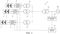
FIG. 1 is a block diagram schematically illustrating a power storage system according to an embodiment. - [
Fig. 2 ]
FIG. 2 is a block diagram schematically illustrating the control device according to the embodiment. - [
Fig. 3 ]
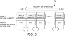
FIG. 3 is an explanatory drawing schematically illustrating an example of the priority list. - Embodiments will now be described with reference to the drawings.
- The drawings are schematic and conceptual; and the relationships between the thicknesses and widths of portions, the proportions of sizes among portions, etc., are not necessarily the same as the actual values. Also, the dimensions and proportions may be illustrated differently among drawings, even for identical portions.
- In the specification and drawings, components similar to those described previously or illustrated in an antecedent drawing are marked with the same reference numerals; and a detailed description is omitted as appropriate.
-
FIG. 1 is a block diagram schematically illustrating a power storage system according to an embodiment. - As illustrated in
FIG. 1 , thepower storage system 2 includes multiplepower storage devices 4, multiplepower conversion devices 6, and acontrol device 10. The multiplepower storage devices 4 can store DC power, can supply (discharge) the stored DC power, and can re-store (be charged with) DC power according to an inflow of DC power that is greater than the stored DC power. The multiplepower storage devices 4 are, for example, storage batteries. The multiplepower storage devices 4 may be, for example, capacitors, etc. The multiplepower storage devices 4 may be any device that can discharge and charge DC power. - The multiple
power conversion devices 6 are provided to correspond respectively to the multiplepower storage devices 4. The number of the multiplepower conversion devices 6 is, for example, equal to the number of the multiplepower storage devices 4. The multiplepower conversion devices 6 are connected respectively to the multiplepower storage devices 4. However, multiplepower storage devices 4 may be connected to onepower conversion device 6. The number of the multiplepower conversion devices 6 may not always be equal to the number of the multiplepower storage devices 4. - The
power storage system 2 further includes, for example,multiple transformers 12 and atransformer 14. Themultiple transformers 12 are provided to correspond respectively to the multiplepower conversion devices 6. The multiplepower conversion devices 6 are connected to themultiple transformers 12. Themultiple transformers 12 are connected to thetransformer 14. Thetransformer 14 is connected to a power system PS. The multiplepower conversion devices 6 are connected with the power system PS that is the load via thetransformers power conversion devices 6 and the power system PS. The configuration between the power system PS and thepower conversion devices 6 may be any configuration that can connect thepower conversion devices 6 to the power system PS. - The power of the power system PS (the load) is AC power. The power of the power system PS is, for example, three-phase AC power. However, the power of the power system PS (the load) is not limited to AC power and may be DC power, etc.
- The multiple
power conversion devices 6 converts the DC power stored in the multiplepower storage devices 4 into power corresponding to the power system PS and converts the power of the power system PS into DC power corresponding to the multiplepower storage devices 4. The multiplepower conversion devices 6 include, for example, multiple switching elements and convert the power by switching the multiple switching elements. - The multiple
power conversion devices 6 supply the power to the power system PS based on the DC power stored in the multiplepower storage devices 4 and charge the multiplepower storage devices 4 based on the power of the power system PS side. Thereby, for example, thepower storage system 2 suppresses the frequency fluctuation of the power system PS. - The
power storage system 2 further includes, for example, ameasurement device 16. For example, themeasurement device 16 detects the active power value, the reactive power value, and the voltage value of the connection point between the power system PS and the multiplepower conversion devices 6 and inputs the active power value, the reactive power value, and the voltage value that are detected to thecontrol device 10. - The
control device 10 controls the power conversion operation of the multiplepower conversion devices 6. For example, thecontrol device 10 controls the operations of the multiplepower conversion devices 6 to suppress the frequency fluctuation of the power system PS based on the active power value, the reactive power value, and the voltage value of the connection point input from themeasurement device 16. -
FIG. 2 is a block diagram schematically illustrating the control device according to the embodiment. - As illustrated in
FIG. 2 , thecontrol device 10 includes an outputvalue determination part 20, anumber determination part 22, a conversiondevice determination part 24, and acommand transmitting part 26. - The output
value determination part 20 determines the total value of the active power and the total value of the reactive power output from the multiplepower conversion devices 6. For example, based on the active power value, the reactive power value, and the voltage value of the connection point input from themeasurement device 16, the outputvalue determination part 20 determines the total value of the active power and the total value of the reactive power output from the multiplepower conversion devices 6 by calculating the active power and the reactive power necessary to suppress the frequency fluctuation of the power system PS. - However, the method for determining the total value of the active power and the total value of the reactive power is not limited to that described above. For example, the output
value determination part 20 may determine the total value of the active power and the total value of the reactive power based on a command value input from a higher-level controller, etc. The method for determining the total value of the active power and the total value of the reactive power may be any method adapted to the system configuration of thepower storage system 2, etc. - The
number determination part 22 determines the number of thepower conversion devices 6 among the multiplepower conversion devices 6 to which the operation command is to be transmitted. - For example, the rated capacity of the active power per one of the multiple
power conversion devices 6, the rated capacity of the reactive power per one of the multiplepower conversion devices 6, the output margin of the active power of the multiplepower conversion devices 6, and the output margin of the reactive power of the multiplepower conversion devices 6 are set as parameters in thenumber determination part 22. In other words, thenumber determination part 22 includes information of the rated capacity of the active power, the rated capacity of the reactive power, the output margin of the active power, and the output margin of the reactive power beforehand. - The
number determination part 22 determines the number of thepower conversion devices 6 to which the operation command is to be transmitted based on the parameters described above and based on the total value of the active power and the total value of the reactive power determined by the outputvalue determination part 20. - The
number determination part 22 calculates a number D1 of thepower conversion devices 6 necessary to output the active power by using the following Formula (1).
- In Formula (1), Ap is the total value of the active power determined by the output
value determination part 20. S1 is the rated capacity of the active power per one of the multiplepower conversion devices 6. B1 is the output margin of the active power of the multiplepower conversion devices 6. Any value between 0 to 1 (p. u.) is set as the output margin B1. Also, round is the roundup function. Thenumber determination part 22 calculates the number D1 as an integer by rounding up digits to the right of the decimal point. - The
number determination part 22 calculates a number D2 of thepower conversion devices 6 necessary to output the reactive power by using the following Formula (2).
- In Formula (2), Aq is the total value of the reactive power determined by the output
value determination part 20. S2 is the rated capacity of the reactive power per one of the multiplepower conversion devices 6. B2 is the output margin of the reactive power of the multiplepower conversion devices 6. Any value between 0 to 1 (p. u.) is set as the output margin B2. Similarly to Formula (1), round is the roundup function. Thenumber determination part 22 calculates the number D2 as an integer by rounding up digits to the right of the decimal point. - After calculating the number D1 of the
power conversion devices 6 necessary to output the active power and the number D2 of thepower conversion devices 6 necessary to output the reactive power, thenumber determination part 22 determines the larger among the numbers D1 and D2 as the number of thepower conversion devices 6 to which the operation command is to be transmitted. - The method for calculating the numbers D1 and D2 is not always limited to that described above. For example, the
number determination part 22 may calculate the numbers D1 and D2 as D1 = Ap/(S1×B1) and D2 = Aq/(S2×B2). In such a case, the output margins B1 and B2 are set to 1 (p. u.) when thepower conversion device 6 is to be operated at the rated capacity, and the output margins B1 and B2 are set to any value less than 1 (p. u.) when the output of thepower conversion device 6 is to be less than the rated capacity. - The output margins B1 and B2 may not always be set. For example, the
number determination part 22 may calculate the numbers D1 and D2 as D1 = Ap/S1 and D2 = Aq/S2. The method for determining the number by thenumber determination part 22 may be any determination method based on at least the total value of the active power and the total value of the reactive power determined by the outputvalue determination part 20. - The conversion
device determination part 24 determines prescribedpower conversion devices 6 among the multiplepower conversion devices 6 of the number determined by thenumber determination part 22 as thepower conversion devices 6 to which the operation command is to be transmitted. The conversiondevice determination part 24 includes, for example, apriority list 30 representing the priorities of the multiplepower conversion devices 6. The conversiondevice determination part 24 determines thepower conversion devices 6 among the multiplepower conversion devices 6 in descending order of the priorities of thepriority list 30 of the number determined by thenumber determination part 22 as thepower conversion devices 6 to which the operation command is to be transmitted. - For example, when the
number determination part 22 determines the number of thepower conversion devices 6 to which the operation command is to be transmitted to be two, the conversiondevice determination part 24 determines the twopower conversion devices 6 having high priorities in thepriority list 30 as thepower conversion devices 6 to which the operation command is to be transmitted. - After determining the
power conversion devices 6 to which the operation command is to be transmitted, the conversiondevice determination part 24 inputs the information of the determinedpower conversion devices 6 to thecommand transmitting part 26. - Based on the information input from the conversion
device determination part 24, thecommand transmitting part 26 transmits the operation command to thepower conversion devices 6 determined by the conversiondevice determination part 24. For example, thecommand transmitting part 26 determines the active power and the reactive power per onepower conversion device 6 by dividing the total value of the active power and the total value of the reactive power determined by the outputvalue determination part 20 by the number determined by thenumber determination part 22 and transmits the operation command to the determinedpower conversion devices 6 to cause the determinedpower conversion devices 6 to output the determined active power and reactive power. - Also, the
command transmitting part 26 transmits a standby command to the remainingpower conversion devices 6 among the multiplepower conversion devices 6 to which the operation command is not to be transmitted. The standby command is a command that stops the operation of thepower conversion device 6. The standby command is, for example, a command that switches the multiple switching elements of thepower conversion device 6 to the off-state. The standby command also may be called a gate block command, etc. - Also, for example, when a circuit breaker or the like is located between the
power conversion device 6 and thepower storage device 4 and between thepower conversion device 6 and the transformer 12 (at the branch point of the multiple power conversion devices 6), the circuit breaker that corresponds to thepower conversion devices 6 to which the standby command is to be transmitted is left in the on-state when thecommand transmitting part 26 transmits the standby command. In other words, when thecommand transmitting part 26 transmits the standby command, thepower conversion device 6 is left in the state of being connected to thepower storage device 4 and the power system PS; and only the operation of thepower conversion device 6 is stopped by the transmission of the standby command. The standby command is, for example, a command that stops the operation of thepower conversion device 6 while allowing thepower conversion device 6 to be operated immediately. - For example, the
control device 10 operates every prescribed control period such as 100 ms, etc. For example, for each control period, thecontrol device 10 determines the total value of the active power and the total value of the reactive power output from the multiplepower conversion devices 6 in the outputvalue determination part 20, determines the number of thepower conversion devices 6 to which the operation command is to be transmitted in thenumber determination part 22, determines thepower conversion devices 6 to which the operation command is to be transmitted in the conversiondevice determination part 24, and transmits the operation command or the standby command from thecommand transmitting part 26 to the multiplepower conversion devices 6. Thereby, thecontrol device 10 controls the operations of the multiplepower conversion devices 6 every prescribed control period. -
FIG. 3 is an explanatory drawing schematically illustrating an example of the priority list. - As illustrated in
FIG. 3 , thepriority list 30 represents the device number, the charge amount (SOC: State Of Charge), and the priority that are associated with each other. Thepriority list 30 is, for example, table data in which the device number, the charge amount, and the priority are associated. - The device numbers are unique numbers assigned respectively to the multiple
power conversion devices 6 to identify the multiplepower conversion devices 6. The charge amounts represent the charge amounts of thepower storage devices 4 connected to thepower conversion devices 6 represented by the device numbers. The priorities represent the priority order of transmitting the operation command to thepower conversion devices 6 represented by the device numbers. - Thus, the
priority list 30 is, for example, table data in which the device numbers and charge amounts corresponding to the multiplepower conversion devices 6 are arranged in descending order of the priorities. - For example, the conversion
device determination part 24 determines the priorities of the multiplepower conversion devices 6 of thepriority list 30 according to the charge amounts of the multiplepower storage devices 4. In such a case, the conversiondevice determination part 24 changes the priorities of the multiplepower conversion devices 6 according to the direction in which the active power of the multiplepower conversion devices 6 is output. - When the output direction of the active power of the multiple
power conversion devices 6 is the discharge direction of supplying the power to the power system PS, the conversiondevice determination part 24 increases the priorities of thepower conversion devices 6 having high charge amounts of thepower storage devices 4. Then, when the output direction of the active power of the multiplepower conversion devices 6 is the charge direction of charging thepower storage devices 4 based on the power of the power system PS, the conversiondevice determination part 24 increases the priorities of thepower conversion devices 6 having low charge amounts of thepower storage device 4. The reduction and/or overcharge of the charge amounts of the multiplepower storage devices 4 can be suppressed thereby. - The charge amounts of the multiple
power storage devices 4 change according to the operations of the multiplepower conversion devices 6. Therefore, when determining the priorities of the multiplepower conversion devices 6 according to the charge amounts of the multiplepower storage devices 4 as described above, the conversiondevice determination part 24 regularly updates the priorities of the multiplepower conversion devices 6. For example, the conversiondevice determination part 24 updates the priorities of the multiplepower conversion devices 6 for each control period of thecontrol device 10. However, the period of updating the priorities may not always be equal to the control period. - When updating the priorities, first, the conversion
device determination part 24 acquires the information of the charge amounts of the multiplepower storage devices 4. In other words, the conversiondevice determination part 24 regularly acquires the information of the charge amounts of the multiplepower storage devices 4. For example, the conversiondevice determination part 24 acquires the information of the charge amounts of the multiplepower storage devices 4 for each control period. The information of the charge amounts of the multiplepower storage devices 4 that is acquired is associated with the device numbers. Thereby, the conversiondevice determination part 24 can recognize the charge amounts of the multiplepower storage devices 4 corresponding respectively to the multiplepower conversion devices 6. - For example, the conversion
device determination part 24 acquires the information of the charge amounts of the multiplepower storage devices 4 from the multiplepower storage devices 4, the multiplepower conversion devices 6, etc. For example, the information of the charge amounts of the multiplepower storage devices 4 may be acquired from a higher-level controller, etc. - After acquiring the information of the charge amounts of the multiple
power storage devices 4, the conversiondevice determination part 24 updates the charge amounts of thepriority list 30 based on the acquired information of the charge amounts. Thereby, the values of the charge amounts of thepriority list 30 are updated to the current values of the charge amounts of the multiplepower storage devices 4. - After updating the charge amounts, based on the total value of the active power output from the multiple
power conversion devices 6 determined by the outputvalue determination part 20, the conversiondevice determination part 24 determines whether the direction in which the active power of the multiplepower conversion devices 6 is output is the direction of discharging from the multiplepower storage devices 4 or the direction of charging the multiplepower storage devices 4. For example, when the discharge direction is positive and the charge direction is negative, the conversiondevice determination part 24 determines the discharge direction or the charge direction based on the sign of the total value of the active power output from the multiplepower conversion devices 6. - When the output direction of the active power is determined to be the discharge direction, the conversion
device determination part 24 increases the priorities of thepower conversion devices 6 having high charge amounts of thepower storage devices 4. Also, when the output direction of the active power is determined to be the charge direction, the conversiondevice determination part 24 increases the priorities of thepower conversion devices 6 having low charge amounts of thepower storage device 4. The determination of the output direction of the active power may be performed before updating the charge amounts. - After updating the charge amounts and determining the output direction of the active power, the conversion
device determination part 24 performs sort processing of the charge amounts after the update. - When the output direction of the active power is determined to be the discharge direction, the conversion
device determination part 24 sorts the device numbers and the charge amounts in descending order of the charge amounts of thepower storage devices 4. Thereby, after the values of the charge amounts of thepriority list 30 are updated to the current values of the charge amounts of the multiplepower storage devices 4, the priorities of the multiplepower conversion devices 6 can be updated to increase the priorities of thepower conversion devices 6 having high charge amounts of thepower storage devices 4. - Also, when the output direction of the active power is determined to be the charge direction, the conversion
device determination part 24 sorts the device numbers and the charge amounts in ascending order of the charge amounts of thepower storage device 4. Thereby, after the values of the charge amounts of thepriority list 30 are updated to the current values of the charge amounts of the multiplepower storage devices 4, the priorities of the multiplepower conversion devices 6 can be updated to increase the priorities of thepower conversion devices 6 having low charge amounts of thepower storage device 4. - For example, the conversion
device determination part 24 performs the sort processing by comparing the charge amounts corresponding to two adjacentpower conversion devices 6 in thepriority list 30. - When the output direction of the active power is the discharge direction, the conversion
device determination part 24 compares the charge amounts corresponding to the two adjacentpower conversion devices 6 in thepriority list 30 in order from the high priority side and interchanges the order of the twopower conversion devices 6 as necessary to increase the priorities of thepower conversion devices 6 having high charge amounts. - At this time, for example, the conversion
device determination part 24 provides a dead band in the comparison of the charge amounts corresponding to the two adjacentpower conversion devices 6. When the difference of the two charge amounts is not less than a prescribed value, the conversiondevice determination part 24 interchanges the order of the twopower conversion devices 6. - For example, the conversion
device determination part 24 compares thepower conversion device 6 having the highest priority and thepower conversion device 6 having the second highest priority, and interchanges the order of the twopower conversion devices 6 when the charge amount that corresponds to thepower conversion device 6 having the second highest priority is greater than the charge amount corresponding to thepower conversion device 6 having the highest priority by a prescribed value. In other words, the priority of thepower conversion device 6 that was second becomes the highest; and the priority of thepower conversion device 6 that was the highest becomes second. - For example, the prescribed value is set to about 2% to 3% of the maximum value of the charge amounts. Thereby, the order of the two
power conversion devices 6 can be prevented from being interchanged too frequently. For example, an undesirable delay in the operations of thepower conversion devices 6 due to the frequent interchange of thepower conversion devices 6 to which the operation command is to be transmitted and thepower conversion devices 6 to which the standby command is to be transmitted can be suppressed. However, the dead band may not always be provided. - The conversion
device determination part 24 sequentially performs the processing described above in order from the high priority side. For example, after comparing thepower conversion device 6 having the highest priority and thepower conversion device 6 having the second highest priority, the conversiondevice determination part 24 compares thepower conversion device 6 having the second highest priority and thepower conversion device 6 having the third highest priority and sequentially performs this comparison. Thereby, when the output direction of the active power is the discharge direction, the conversiondevice determination part 24 sorts the charge amounts after the update in descending order of the charge amounts. In contrast to the description described above, when the output direction of the active power is the discharge direction, the charge amounts that correspond to two adjacentpower conversion devices 6 in thepriority list 30 may be compared in order from the low priority side. - When the output direction of the active power is the charge direction, the conversion
device determination part 24 compares the charge amounts corresponding to the two adjacentpower conversion devices 6 in thepriority list 30 in order from the high priority side and interchanges the order of the twopower conversion devices 6 as necessary to increase the priority of thepower conversion device 6 having the lower charge amount. Thereby, when the output direction of the active power is the charge direction, the conversiondevice determination part 24 sorts the charge amounts after the update in ascending order of the charge amounts. In contrast to the description described above, when the output direction of the active power is the charge direction, the charge amounts corresponding to the two adjacentpower conversion devices 6 in thepriority list 30 may be compared in order from the low priority side. - For example, the conversion
device determination part 24 performs the comparison processing of the charge amounts described above to perform (N×(N - 1))/2 iterations, where N is the number of the multiplepower conversion devices 6. More specifically, N is the number of thepower conversion devices 6 among the multiplepower conversion devices 6 that can be operated. - When comparing two adjacent charge amounts, the comparison iterations necessary to compare all of the charge amounts of the
priority list 30 once each is N - 1 iterations. For example, when the number of the multiplepower conversion devices 6 is five, the comparison iterations necessary to compare all of the charge amounts of thepriority list 30 once each is a total of 4 iterations, i.e., the first and second priorities, the second and third priorities, the third and fourth priorities, and the fourth and fifth priorities. Thereby, the comparison can be performed once each from the charge amount of thepower conversion device 6 having the highest priority to the charge amount of thepower conversion device 6 having the lowest priority. - Thus, the
power conversion device 6 having the highest priority or thepower conversion device 6 having the lowest priority can be finalized by performing the comparison N - 1 iterations. For example, when comparing the charge amounts in order from the high priority side and interchanging the order of the twopower conversion devices 6 as necessary to increase the priorities of thepower conversion devices 6 having high charge amounts, thepower conversion device 6 having the lowest priority can be finalized by performing the comparison N - 1 iterations. Conversely, when comparing the charge amounts in order from the low priority side and interchanging the order of the twopower conversion devices 6 as necessary to increase the priorities of thepower conversion devices 6 having high charge amounts, thepower conversion device 6 having the highest priority can be finalized by performing the comparison N - 1 iterations. - When continuing the comparison, the conversion
device determination part 24 repeats similar processing for the remainingpower conversion devices 6 other than the finalizedpower conversion devices 6. - For example, when the number of the multiple
power conversion devices 6 is five, the fifthpower conversion device 6 is finalized by comparing the first and second priorities, the second and third priorities, the third and fourth priorities, and the fourth and fifth priorities, after which the fourthpower conversion device 6 is finalized by comparing the first and second priorities, the second and third priorities, and the third and fourth priorities; the thirdpower conversion device 6 is finalized by comparing the first and second priorities and the second and third priorities; and the first and secondpower conversion devices 6 are finalized by comparing the first and second priorities. Thereby, thepower conversion devices 6 can be sorted in an order corresponding to the charge amounts from the first to the fifth. In such a case, the comparison iterations are 10 (4 + 3 +2 +1) iterations, which match (5×(5-1))/2 = 10. - By sorting as described above, the N
power conversion devices 6 can be appropriately sorted in an order corresponding to the charge amounts by the number of iterations determined from the formula above. Thereby, for example, the iterations of the comparison calculation can be less than when (N - 1) calculations are repeated N times, etc. The Npower conversion devices 6 can be appropriately sorted in an order corresponding to the charge amounts by relatively few calculation iterations. - By regularly performing the processing of the comparison of the charge amounts (N×(N - 1))/2 iterations, the conversion
device determination part 24 sorts the charge amounts after the update in descending order of the charge amounts when the output direction of the active power is the discharge direction, and sorts the charge amounts after the update in ascending order of the charge amounts when the output direction of the active power is the charge direction. - For example, when updating the priorities for each control period of the
control device 10, the conversiondevice determination part 24 performs the sort processing of the charge amounts after the update as described above, subsequently determines thepower conversion devices 6 among the multiplepower conversion devices 6 of the number determined by thenumber determination part 22 in descending order of the priorities of thepriority list 30 as thepower conversion devices 6 to which the operation command is to be transmitted, and inputs the information of the determinedpower conversion devices 6 to thecommand transmitting part 26. - The period of the update of the priorities may be set to be longer than the control period. For example, the update of the priorities may be performed at a frequency of once every two control periods, a frequency of once every three control periods, etc.
- In the example above, the conversion
device determination part 24 sorts all of the device numbers and charge amounts in the descending order of the charge amounts of thepower storage devices 4 or in ascending order of the charge amounts of thepower storage devices 4 for each period of the updating of the priorities. However, the sort processing of the charge amounts after the update is not limited to that described above. - For example, the conversion
device determination part 24 may compare the charge amounts corresponding to two adjacentpower conversion devices 6 in thepriority list 30 in order from the high priority side or the low priority side for each period of the updating of the priorities and perform processing of interchanging the order of the twopower conversion devices 6 as necessary once each for all of the charge amounts of thepriority list 30. - In other words, the conversion
device determination part 24 may finalize thepower conversion device 6 having the highest priority or thepower conversion device 6 having the lowest priority by performing the N - 1 iterations of the comparison of the example above for each period of the updating of the priorities. In such a case as well, the conversiondevice determination part 24 may provide a dead band in the comparison of the charge amounts corresponding to the two adjacentpower conversion devices 6. - When all of the device numbers and charge amounts are sorted for each period of the updating of the priorities as in the example above, there is a possibility that the
power conversion devices 6 to which the operation command is to be transmitted and thepower conversion devices 6 to which the standby command is to be transmitted may be largely interchanged when the output direction of the active power is changed. - For example, when the number of the multiple
power conversion devices 6 is ten, and when the output direction of the active power is changed in a state in which the operation command is transmitted to fivepower conversion devices 6 among the tenpower conversion devices 6 and the standby command is transmitted to the remaining fivepower conversion devices 6, there is a possibility that thepower conversion devices 6 in the operating state and thepower conversion devices 6 in the standby state may be interchanged at one time. In such a case, there is a possibility that the operations of the multiplepower conversion devices 6 may be delayed, etc. - In contrast, when N - 1 iterations of the comparison are performed for each period of the updating of the priorities, even when the output direction of the active power is changed, a large interchange of the
power conversion devices 6 to which the operation command is to be transmitted and thepower conversion devices 6 to which the standby command is to be transmitted can be suppressed. - For example, when the number of the multiple
power conversion devices 6 is ten, and when the output direction of the active power is changed in a state in which the operation command is transmitted to fivepower conversion devices 6 among the tenpower conversion devices 6 and the standby command is transmitted to the remaining fivepower conversion devices 6, thepower conversion devices 6 to which the operation command is to be transmitted and thepower conversion devices 6 to which the standby command is to be transmitted can be interchanged one at a time in descending order of the charge amounts or in ascending order of the charge amounts for each period of the updating of the priorities. A delay of the operations of the multiplepower conversion devices 6, etc., can be suppressed thereby. - For example, the conversion
device determination part 24 may perform 2×(N - 1) iterations of the comparison for each period of the updating of the priorities. In such a case, when the output direction of the active power is changed, thepower conversion devices 6 to which the operation command is to be transmitted and thepower conversion devices 6 to which the standby command is to be transmitted can be interchanged two at a time in descending order of the charge amounts or in ascending order of the charge amounts for each period of the updating of the priorities. It is sufficient to set the comparison iterations by the conversiondevice determination part 24 to any number of iterations between N - 1 iterations and (N×(N - 1))/2 iterations. - The priorities of the multiple
power conversion devices 6 may not always be determined according to the charge amounts of the multiplepower storage devices 4. Thepriority list 30 may represent the device numbers and the priorities associated with each other. For example, there are cases where the capacities of the multiplepower storage devices 4 and the capacities of the multiplepower conversion devices 6 are different in thepower storage system 2. In such a case, the priorities of the multiplepower conversion devices 6 may be determined according to the capacities of the multiplepower storage devices 4 or the capacities of the multiplepower conversion devices 6. For example, the priorities of the multiplepower conversion devices 6 may be determined in descending order of the capacities of the multiplepower storage devices 4 or the capacities of the multiplepower conversion devices 6. - Also, the method for determining the
power conversion devices 6 to which the operation command is to be transmitted by the conversiondevice determination part 24 is not limited to a method that determines in descending order of the priorities of thepriority list 30. For example, the conversiondevice determination part 24 may determine thepower conversion devices 6 to which the operation command is to be transmitted based on a control signal input from an external device such as a higher-level controller, etc. - In the
power storage system 2 according to the embodiment as described above, thecontrol device 10 determines the number of thepower conversion devices 6 among the multiplepower conversion devices 6 to which the operation command is to be transmitted based on the total value of the active power and the total value of the reactive power output from the multiplepower conversion devices 6, and transmits the operation command to the prescribedpower conversion devices 6 of the determined number and transmits the standby command to the remainingpower conversion devices 6. - Thereby, in the
power storage system 2 and thecontrol device 10 according to the embodiment, the power loss accompanying the operations of the multiplepower conversion devices 6 can be suppressed compared to a control method in which all of the multiplepower conversion devices 6 are operated regardless of the magnitude of the power necessary for the power system PS (the load). - An example is shown in the embodiments described above in which the power system PS is used as a load, and the
power storage system 2 is applied to the power system PS. The application of thepower storage system 2 is not limited to the power system PS; for example, thepower storage system 2 is applicable to an electric vehicle such as an electric locomotive, an electric car, etc. For example, the motor of the electric vehicle is used as the load; the multiplepower conversion devices 6 are connected to the motor; and thepower storage system 2 described above is applicable when supplying the power to the motor and using the regenerative energy of the motor to charge the multiplepower storage devices 4. The load to which thepower storage system 2 is applied is not limited to the power system PS or an electric vehicle, and may be any load for which the supply of the power to the load and the charge of the multiplepower storage devices 4 by the power of the load side can be performed. - Hereinabove, exemplary embodiments of the invention are described with reference to specific examples. However, embodiments of the invention are not limited to these specific examples. For example, one skilled in the art may similarly practice the invention by appropriately selecting specific configurations of components included in the
power storage system 2 and thecontrol device 10 from known art, and such practice is within the scope of the invention to the extent that similar effects can be obtained. - Furthermore, combinations of any two or more components of the specific examples within the extent of technical feasibility also are within the scope of the invention to the extent that the purport of the invention is included.
- Furthermore, all power storage systems and control devices practicable by an appropriate design modification by one skilled in the art based on the
power storage system 2 and thecontrol device 10 described above as embodiments of the invention also are within the scope of the invention to the extent that the purport of the invention is included. - Furthermore, various modifications and alterations within the spirit of the invention will be readily apparent to those skilled in the art; and all such modifications and alterations should be seen as being within the scope of the invention.
- Although several embodiments of the invention are described, these embodiments are presented as examples and are not intended to limit the scope of the invention. These novel embodiments may be carried out in other various forms; and various omissions, substitutions, and modifications can be performed without departing from the spirit of the invention. Such embodiments and their modifications are within the scope and spirit of the invention and are included in the invention described in the claims and their equivalents.
Claims (11)
- A power storage system, comprising:a plurality of power storage devices capable of discharging and charging direct current power;a plurality of power conversion devices connected to the plurality of power storage devices and a load, the plurality of power conversion devices converting the direct current power stored in the plurality of power storage devices into power corresponding to the load, the plurality of power conversion devices supplying the power to the load based on the direct current power stored in the plurality of power storage devices, the plurality of power conversion devices converting power of the load into direct current power corresponding to the plurality of power storage devices, the plurality of power conversion devices charging the plurality of power storage devices based on the power of the load side; anda control device controlling a power conversion operation of the plurality of power conversion devices,the control device includingan output value determination part determining a total value of active power and a total value of reactive power output from the plurality of power conversion devices,a number determination part determining, based on the total value of the active power and the total value of the reactive power, a number of the power conversion devices among the plurality of power conversion devices to which an operation command is to be transmitted,a conversion device determination part determining, as the power conversion devices to which the operation command is to be transmitted, prescribed power conversion devices among the plurality of power conversion devices of the number determined by the number determination part, anda command transmitting part transmitting the operation command to the power conversion devices determined by the conversion device determination part and transmitting a standby command to the remaining power conversion devices among the plurality of power conversion devices to which the operation command is not transmitted.
- The power storage system according to claim 1, wherein
the number determination part includes information of a rated capacity of the active power per one of the plurality of power conversion devices and a rated capacity of the reactive power per one of the plurality of power conversion devices, and determines the number of the power conversion devices to which the operation command is to be transmitted based on the rated capacity of the active power, the rated capacity of the reactive power, and the total value of the active power and the total value of the reactive power determined by the output value determination part. - The power storage system according to claim 1, wherein
the conversion device determination part includes a priority list representing priorities of the plurality of power conversion devices and determines, as the power conversion devices to which the operation command is to be transmitted, the power conversion devices among the plurality of power conversion devices of the number determined by the number determination part in descending order of the priorities of the priority list. - The power storage system according to claim 3, whereinthe priority list represents the priorities by associating device numbers for identifying the plurality of power conversion devices, charge amounts of the power storage devices connected to the power conversion devices represented by the device numbers, and the priorities representing a priority order of transmitting the operation command to the power conversion devices represented by the device numbers, andthe conversion device determination part determines the priorities of the plurality of power conversion devices of the priority list according to the charge amounts of the plurality of power storage devices.
- The power storage system according to claim 4, whereinwhen an output direction of the active power of the plurality of power conversion devices is a discharge direction of supplying the power to the load, the conversion device determination part increases the priorities of the power conversion devices having high charge amounts of the power storage devices, andwhen the output direction of the active power of the plurality of power conversion devices is a charge direction of charging the power storage devices based on the power of the load, the conversion device determination part increases the priorities of the power conversion devices having low charge amounts of the power storage devices.
- The power storage system according to claim 4, wherein
the conversion device determination part regularly updates the priorities of the plurality of power conversion devices of the priority list byregularly acquiring information of the charge amounts of the plurality of power storage devices,updating the charge amounts of the priority list based on the acquired information of the charge amounts, andperforming sort processing of the charge amounts after the updating. - The power storage system according to claim 6, whereinwhen an output direction of the active power of the plurality of power conversion devices is a discharge direction of supplying the power to the load, the conversion device determination part sorts the device numbers and the charge amounts in descending order of the charge amounts of the power storage devices, andwhen the output direction of the active power of the plurality of power conversion devices is a charge direction of charging the power storage devices based on the power of the load, the conversion device determination part sorts the device numbers and the charge amounts in ascending order of the charge amounts of the power storage devices.
- The power storage system according to claim 7, whereinwhen the output direction of the active power is the discharge direction, the conversion device determination part:compares the charge amounts corresponding to two of the adjacent power conversion devices in the priority list in order from a high priority side or a low priority side;performs processing of interchanging the order of the two power conversion devices as necessary to increase the priority of the power conversion device having the higher charge amount;finalizes the power conversion device having the highest priority or the power conversion device having the lowest priority by performing the processing once each from the charge amount of the power conversion device having the highest priority to the charge amount of the power conversion device having the lowest priority; andsorts the charge amounts after the updating in descending order of the charge amounts by repeating similar processing for the remaining power conversion devices other than the finalized power conversion device to cause an iteration of the comparison to be (N×(N - 1))/2 iterations, where N is the number of the plurality of power conversion devices, andwhen the output direction of the active power is the charge direction, the conversion device determination part:compares the charge amounts corresponding to two of the adjacent power conversion devices in the priority list in order from the high priority side or the low priority side;performs processing of interchanging the order of the two power conversion devices as necessary to increase the priority of the power conversion device having the lower charge amount;finalizes the power conversion device having the highest priority or the power conversion device having the lowest priority by performing the processing once each from the charge amount of the power conversion device having the highest priority to the charge amount of the power conversion device having the lowest priority; andsorts the charge amounts after the updating in ascending order of the charge amounts by repeating similar processing for the remaining power conversion devices other than the finalized power conversion device to cause the iteration of the comparison to be (N×(N - 1))/2 iterations.
- The power storage system according to claim 8, wherein
when comparing the charge amounts corresponding to the two adjacent power conversion devices, the conversion device determination part interchanges the order of the two power conversion devices when a difference of the two charge amounts is not less than a prescribed value. - The power storage system according to claim 6, wherein
for each period of the updating of the priorities, the conversion device determination partcompares the charge amounts corresponding to two of the adjacent power conversion devices in the priority list in order from a high priority side or a low priority side, andperforms processing of interchanging the order of the two power conversion devices as necessary once each for all of the charge amounts of the priority list. - A control device,the control device controlling a power conversion operation of a plurality of power conversion devices,the plurality of power conversion devices being connected to a plurality of power storage devices and a load,the plurality of power conversion devices converting direct current power stored in the plurality of power storage devices into power corresponding to the load,the plurality of power conversion devices supplying the power to the load based on the direct current power stored in the plurality of power storage devices,the plurality of power conversion devices converting power of the load into direct current power corresponding to the plurality of power storage devices,the plurality of power conversion devices charging the plurality of power storage devices based on the power of the load side,the control device comprising:an output value determination part determining a total value of active power and a total value of reactive power output from the plurality of power conversion devices;a number determination part determining, based on the total value of the active power and the total value of the reactive power, a number of the power conversion devices among the plurality of power conversion devices to which an operation command is to be transmitted;a conversion device determination part determining, as the power conversion devices to which the operation command is to be transmitted, prescribed power conversion devices among the plurality of power conversion devices of the number determined by the number determination part; anda command transmitting part transmitting the operation command to the power conversion devices determined by the conversion device determination part and transmitting a standby command to the remaining power conversion devices among the plurality of power conversion devices to which the operation command is not transmitted.
Applications Claiming Priority (1)
| Application Number | Priority Date | Filing Date | Title |
|---|---|---|---|
| PCT/JP2021/005870 WO2022176052A1 (en) | 2021-02-17 | 2021-02-17 | Electricity storage system and control device |
Publications (2)
| Publication Number | Publication Date |
|---|---|
| EP4297231A1 true EP4297231A1 (en) | 2023-12-27 |
| EP4297231A4 EP4297231A4 (en) | 2025-02-19 |
Family
ID=82930315
Family Applications (1)
| Application Number | Title | Priority Date | Filing Date |
|---|---|---|---|
| EP21926492.6A Pending EP4297231A4 (en) | 2021-02-17 | 2021-02-17 | POWER STORAGE SYSTEM AND CONTROL DEVICE |
Country Status (4)
| Country | Link |
|---|---|
| US (1) | US12113364B2 (en) |
| EP (1) | EP4297231A4 (en) |
| JP (1) | JP7495775B2 (en) |
| WO (1) | WO2022176052A1 (en) |
Families Citing this family (3)
| Publication number | Priority date | Publication date | Assignee | Title |
|---|---|---|---|---|
| US20250211088A1 (en) * | 2023-01-18 | 2025-06-26 | Tmeic Corporation | Power storage system and control device |
| CN119627987A (en) * | 2023-09-13 | 2025-03-14 | 台达电子工业股份有限公司 | Energy storage system and control method thereof |
| CN118174427B (en) * | 2024-04-15 | 2025-02-11 | 中远海运发展股份有限公司 | A method for parallel operation of a box-type power supply multi-battery system |
Family Cites Families (5)
| Publication number | Priority date | Publication date | Assignee | Title |
|---|---|---|---|---|
| JP3890168B2 (en) | 1999-08-03 | 2007-03-07 | 株式会社東京アールアンドデー | Electric device and charging / discharging method of battery unit thereof |
| JP5851879B2 (en) | 2012-02-21 | 2016-02-03 | 三菱重工業株式会社 | Power control device |
| JP5924524B2 (en) | 2012-03-13 | 2016-05-25 | オムロン株式会社 | Storage battery control device, storage battery control method, program, power storage system, and power supply system |
| JP6452906B1 (en) * | 2018-03-23 | 2019-01-16 | 三菱電機株式会社 | Power converter |
| CN112840520B (en) | 2018-10-23 | 2024-07-26 | 三菱电机株式会社 | System, control device, control method for system, and power conversion device |
-
2021
- 2021-02-17 WO PCT/JP2021/005870 patent/WO2022176052A1/en not_active Ceased
- 2021-02-17 US US17/922,384 patent/US12113364B2/en active Active
- 2021-02-17 EP EP21926492.6A patent/EP4297231A4/en active Pending
- 2021-02-17 JP JP2023500178A patent/JP7495775B2/en active Active
Also Published As
| Publication number | Publication date |
|---|---|
| JP7495775B2 (en) | 2024-06-05 |
| EP4297231A4 (en) | 2025-02-19 |
| JPWO2022176052A1 (en) | 2022-08-25 |
| US12113364B2 (en) | 2024-10-08 |
| US20230187941A1 (en) | 2023-06-15 |
| WO2022176052A1 (en) | 2022-08-25 |
Similar Documents
| Publication | Publication Date | Title |
|---|---|---|
| US12113364B2 (en) | Power storage system and control device | |
| EP4080722B1 (en) | Energy storage system, balancing control method for energy storage system, and photovoltaic power system | |
| EP3506451B1 (en) | Quick charging method for series battery pack, and related device | |
| EP3836376B1 (en) | Voltage balance control method for flying-capacitor multilevel converter | |
| KR102730536B1 (en) | System of vehicle including solar cell and method for controlling the same | |
| US10263434B2 (en) | Charge and discharge device, charge and discharge control method, and program | |
| US10651772B2 (en) | Inverter system for vehicle and control method thereof | |
| US20160276847A1 (en) | Battery cell balancing method | |
| US20110156620A1 (en) | Battery protection system and method thereof | |
| EP3893376A1 (en) | Power conversion method | |
| CN112438005A (en) | Method and device for charging an electrical energy store | |
| EP3540902B1 (en) | Power supply system including high-voltage system and low-voltage system | |
| KR20210058660A (en) | Method and control device for operating a battery system and battery system | |
| EP4369564A1 (en) | Power conversion device and charging station | |
| KR101591931B1 (en) | Device for controling Formation of Secondary Battery | |
| US20240039414A1 (en) | Power Conversion Device | |
| EP4521620A1 (en) | Charging device and charging control method | |
| US20250317000A1 (en) | Charge/discharge control device, charge/discharge control method, and program | |
| EP4654417A1 (en) | Electricity storage system and control device | |
| EP3641094A1 (en) | Battery balancing system and method of operating a battery balancing system | |
| JP7055945B2 (en) | Storage battery system | |
| WO2011007329A2 (en) | Method for the operation of an energy storage arrangement in a vehicle and vehicle with an energy storage arrangement | |
| CN117424300A (en) | Voltage equalization during charging of multiple battery packs | |
| Gallardo-Lozano et al. | A battery cell balancing method with linear mode bypass current control | |
| WO2022250744A1 (en) | Automated battery charging |
Legal Events
| Date | Code | Title | Description |
|---|---|---|---|
| STAA | Information on the status of an ep patent application or granted ep patent |
Free format text: STATUS: THE INTERNATIONAL PUBLICATION HAS BEEN MADE |
|
| PUAI | Public reference made under article 153(3) epc to a published international application that has entered the european phase |
Free format text: ORIGINAL CODE: 0009012 |
|
| STAA | Information on the status of an ep patent application or granted ep patent |
Free format text: STATUS: REQUEST FOR EXAMINATION WAS MADE |
|
| 17P | Request for examination filed |
Effective date: 20221028 |
|
| AK | Designated contracting states |
Kind code of ref document: A1 Designated state(s): AL AT BE BG CH CY CZ DE DK EE ES FI FR GB GR HR HU IE IS IT LI LT LU LV MC MK MT NL NO PL PT RO RS SE SI SK SM TR |
|
| DAV | Request for validation of the european patent (deleted) | ||
| DAX | Request for extension of the european patent (deleted) | ||
| A4 | Supplementary search report drawn up and despatched |
Effective date: 20250121 |
|
| RIC1 | Information provided on ipc code assigned before grant |
Ipc: H02J 3/38 20060101ALI20250115BHEP Ipc: H02J 3/32 20060101ALI20250115BHEP Ipc: H02J 3/16 20060101ALI20250115BHEP Ipc: H02J 7/00 20060101AFI20250115BHEP |