EP4297168A1 - Gas collection device - Google Patents
Gas collection device Download PDFInfo
- Publication number
- EP4297168A1 EP4297168A1 EP22911549.8A EP22911549A EP4297168A1 EP 4297168 A1 EP4297168 A1 EP 4297168A1 EP 22911549 A EP22911549 A EP 22911549A EP 4297168 A1 EP4297168 A1 EP 4297168A1
- Authority
- EP
- European Patent Office
- Prior art keywords
- jig
- battery
- housing
- gas
- gas discharge
- Prior art date
- Legal status (The legal status is an assumption and is not a legal conclusion. Google has not performed a legal analysis and makes no representation as to the accuracy of the status listed.)
- Pending
Links
- 238000003780 insertion Methods 0.000 claims description 57
- 230000037431 insertion Effects 0.000 claims description 57
- 230000001174 ascending effect Effects 0.000 claims description 20
- 238000003825 pressing Methods 0.000 claims description 10
- 238000004080 punching Methods 0.000 claims description 10
- 230000000149 penetrating effect Effects 0.000 claims description 3
- 239000000463 material Substances 0.000 abstract description 7
- 239000007789 gas Substances 0.000 description 120
- 238000009792 diffusion process Methods 0.000 description 8
- 238000007789 sealing Methods 0.000 description 8
- 238000000034 method Methods 0.000 description 7
- 238000004458 analytical method Methods 0.000 description 5
- 230000008569 process Effects 0.000 description 5
- 229910052744 lithium Inorganic materials 0.000 description 4
- WHXSMMKQMYFTQS-UHFFFAOYSA-N Lithium Chemical compound [Li] WHXSMMKQMYFTQS-UHFFFAOYSA-N 0.000 description 3
- HBBGRARXTFLTSG-UHFFFAOYSA-N Lithium ion Chemical compound [Li+] HBBGRARXTFLTSG-UHFFFAOYSA-N 0.000 description 3
- 238000007599 discharging Methods 0.000 description 3
- 229910001416 lithium ion Inorganic materials 0.000 description 3
- 239000000126 substance Substances 0.000 description 3
- IJGRMHOSHXDMSA-UHFFFAOYSA-N Atomic nitrogen Chemical compound N#N IJGRMHOSHXDMSA-UHFFFAOYSA-N 0.000 description 2
- CURLTUGMZLYLDI-UHFFFAOYSA-N Carbon dioxide Chemical compound O=C=O CURLTUGMZLYLDI-UHFFFAOYSA-N 0.000 description 2
- 230000008878 coupling Effects 0.000 description 2
- 238000010168 coupling process Methods 0.000 description 2
- 238000005859 coupling reaction Methods 0.000 description 2
- 238000013461 design Methods 0.000 description 2
- 238000011161 development Methods 0.000 description 2
- 238000009434 installation Methods 0.000 description 2
- 238000004519 manufacturing process Methods 0.000 description 2
- UGFAIRIUMAVXCW-UHFFFAOYSA-N Carbon monoxide Chemical compound [O+]#[C-] UGFAIRIUMAVXCW-UHFFFAOYSA-N 0.000 description 1
- 239000004809 Teflon Substances 0.000 description 1
- 229920006362 Teflon® Polymers 0.000 description 1
- QVGXLLKOCUKJST-UHFFFAOYSA-N atomic oxygen Chemical compound [O] QVGXLLKOCUKJST-UHFFFAOYSA-N 0.000 description 1
- 230000008901 benefit Effects 0.000 description 1
- 230000015572 biosynthetic process Effects 0.000 description 1
- 238000009937 brining Methods 0.000 description 1
- OJIJEKBXJYRIBZ-UHFFFAOYSA-N cadmium nickel Chemical compound [Ni].[Cd] OJIJEKBXJYRIBZ-UHFFFAOYSA-N 0.000 description 1
- 229910002092 carbon dioxide Inorganic materials 0.000 description 1
- 239000001569 carbon dioxide Substances 0.000 description 1
- 229910002091 carbon monoxide Inorganic materials 0.000 description 1
- 238000006243 chemical reaction Methods 0.000 description 1
- 238000000354 decomposition reaction Methods 0.000 description 1
- 230000006866 deterioration Effects 0.000 description 1
- 230000000694 effects Effects 0.000 description 1
- 239000013013 elastic material Substances 0.000 description 1
- 239000003792 electrolyte Substances 0.000 description 1
- 238000005516 engineering process Methods 0.000 description 1
- 239000003779 heat-resistant material Substances 0.000 description 1
- 229930195733 hydrocarbon Natural products 0.000 description 1
- 150000002430 hydrocarbons Chemical class 0.000 description 1
- 239000001257 hydrogen Substances 0.000 description 1
- 229910052739 hydrogen Inorganic materials 0.000 description 1
- 125000004435 hydrogen atom Chemical class [H]* 0.000 description 1
- 230000007257 malfunction Effects 0.000 description 1
- 230000007246 mechanism Effects 0.000 description 1
- 229910052987 metal hydride Inorganic materials 0.000 description 1
- 238000012986 modification Methods 0.000 description 1
- 230000004048 modification Effects 0.000 description 1
- 229910052757 nitrogen Inorganic materials 0.000 description 1
- 238000005457 optimization Methods 0.000 description 1
- 239000001301 oxygen Substances 0.000 description 1
- 229910052760 oxygen Inorganic materials 0.000 description 1
- 229920000642 polymer Polymers 0.000 description 1
- 238000000926 separation method Methods 0.000 description 1
Images


Classifications
-
- H—ELECTRICITY
- H01—ELECTRIC ELEMENTS
- H01M—PROCESSES OR MEANS, e.g. BATTERIES, FOR THE DIRECT CONVERSION OF CHEMICAL ENERGY INTO ELECTRICAL ENERGY
- H01M50/00—Constructional details or processes of manufacture of the non-active parts of electrochemical cells other than fuel cells, e.g. hybrid cells
- H01M50/30—Arrangements for facilitating escape of gases
- H01M50/35—Gas exhaust passages comprising elongated, tortuous or labyrinth-shaped exhaust passages
- H01M50/367—Internal gas exhaust passages forming part of the battery cover or case; Double cover vent systems
-
- H—ELECTRICITY
- H01—ELECTRIC ELEMENTS
- H01M—PROCESSES OR MEANS, e.g. BATTERIES, FOR THE DIRECT CONVERSION OF CHEMICAL ENERGY INTO ELECTRICAL ENERGY
- H01M50/00—Constructional details or processes of manufacture of the non-active parts of electrochemical cells other than fuel cells, e.g. hybrid cells
- H01M50/30—Arrangements for facilitating escape of gases
- H01M50/394—Gas-pervious parts or elements
-
- H—ELECTRICITY
- H01—ELECTRIC ELEMENTS
- H01M—PROCESSES OR MEANS, e.g. BATTERIES, FOR THE DIRECT CONVERSION OF CHEMICAL ENERGY INTO ELECTRICAL ENERGY
- H01M10/00—Secondary cells; Manufacture thereof
- H01M10/05—Accumulators with non-aqueous electrolyte
- H01M10/052—Li-accumulators
- H01M10/0525—Rocking-chair batteries, i.e. batteries with lithium insertion or intercalation in both electrodes; Lithium-ion batteries
-
- H—ELECTRICITY
- H01—ELECTRIC ELEMENTS
- H01M—PROCESSES OR MEANS, e.g. BATTERIES, FOR THE DIRECT CONVERSION OF CHEMICAL ENERGY INTO ELECTRICAL ENERGY
- H01M50/00—Constructional details or processes of manufacture of the non-active parts of electrochemical cells other than fuel cells, e.g. hybrid cells
- H01M50/10—Primary casings; Jackets or wrappings
- H01M50/102—Primary casings; Jackets or wrappings characterised by their shape or physical structure
- H01M50/107—Primary casings; Jackets or wrappings characterised by their shape or physical structure having curved cross-section, e.g. round or elliptic
-
- H—ELECTRICITY
- H01—ELECTRIC ELEMENTS
- H01M—PROCESSES OR MEANS, e.g. BATTERIES, FOR THE DIRECT CONVERSION OF CHEMICAL ENERGY INTO ELECTRICAL ENERGY
- H01M50/00—Constructional details or processes of manufacture of the non-active parts of electrochemical cells other than fuel cells, e.g. hybrid cells
- H01M50/10—Primary casings; Jackets or wrappings
- H01M50/147—Lids or covers
- H01M50/148—Lids or covers characterised by their shape
- H01M50/152—Lids or covers characterised by their shape for cells having curved cross-section, e.g. round or elliptic
-
- H—ELECTRICITY
- H01—ELECTRIC ELEMENTS
- H01M—PROCESSES OR MEANS, e.g. BATTERIES, FOR THE DIRECT CONVERSION OF CHEMICAL ENERGY INTO ELECTRICAL ENERGY
- H01M50/00—Constructional details or processes of manufacture of the non-active parts of electrochemical cells other than fuel cells, e.g. hybrid cells
- H01M50/20—Mountings; Secondary casings or frames; Racks, modules or packs; Suspension devices; Shock absorbers; Transport or carrying devices; Holders
- H01M50/262—Mountings; Secondary casings or frames; Racks, modules or packs; Suspension devices; Shock absorbers; Transport or carrying devices; Holders with fastening means, e.g. locks
-
- H—ELECTRICITY
- H01—ELECTRIC ELEMENTS
- H01M—PROCESSES OR MEANS, e.g. BATTERIES, FOR THE DIRECT CONVERSION OF CHEMICAL ENERGY INTO ELECTRICAL ENERGY
- H01M50/00—Constructional details or processes of manufacture of the non-active parts of electrochemical cells other than fuel cells, e.g. hybrid cells
- H01M50/30—Arrangements for facilitating escape of gases
- H01M50/35—Gas exhaust passages comprising elongated, tortuous or labyrinth-shaped exhaust passages
- H01M50/358—External gas exhaust passages located on the battery cover or case
-
- Y—GENERAL TAGGING OF NEW TECHNOLOGICAL DEVELOPMENTS; GENERAL TAGGING OF CROSS-SECTIONAL TECHNOLOGIES SPANNING OVER SEVERAL SECTIONS OF THE IPC; TECHNICAL SUBJECTS COVERED BY FORMER USPC CROSS-REFERENCE ART COLLECTIONS [XRACs] AND DIGESTS
- Y02—TECHNOLOGIES OR APPLICATIONS FOR MITIGATION OR ADAPTATION AGAINST CLIMATE CHANGE
- Y02E—REDUCTION OF GREENHOUSE GAS [GHG] EMISSIONS, RELATED TO ENERGY GENERATION, TRANSMISSION OR DISTRIBUTION
- Y02E60/00—Enabling technologies; Technologies with a potential or indirect contribution to GHG emissions mitigation
- Y02E60/10—Energy storage using batteries
Definitions
- the present disclosure relates to a gas collecting apparatus, more specifically, to a gas collecting apparatus capable of collecting high-concentration gas for a battery that has a case made of a rigid material with various specifications, particularly a cylindrical battery.
- a secondary battery is a battery that is repeatedly usable through a discharging process to convert chemical energy into electrical energy and a charging process that is performed in a reverse way, types of which include nickel-cadmium (Ni-Cd) batteries, nickel-metal hydride (Ni-MH) batteries, lithium-metal batteries, lithium-ion batteries, and lithium-ion polymer batteries.
- Ni-Cd nickel-cadmium
- Ni-MH nickel-metal hydride
- lithium-metal batteries lithium-ion batteries
- lithium-ion polymer batteries lithium-ion polymer batteries.
- Used as a method of collecting gas generated inside a secondary battery is a method which includes accommodating a battery in a diffusion chamber having a closed space formed therein, forming an opening for discharging gas in a battery case, and collecting the diffused gas in a separate gas collection container when the gas discharged through the opening is diffused inside the diffusion chamber.
- a method which includes accommodating a battery in a diffusion chamber having a closed space formed therein, forming an opening for discharging gas in a battery case, and collecting the diffused gas in a separate gas collection container when the gas discharged through the opening is diffused inside the diffusion chamber.
- batteries are used in a wide range of industries, performance required for batteries also varies depending on various application environments and conditions for the battery, and the batteries may be designed in various specifications.
- a gas collecting apparatus of the present disclosure may include
- a punching portion configured to form a gas discharge hole by perforating an upper end of the battery may be provided.
- a needle passage hole may be formed on an upper surface of the upper housing, and the punching portion may include a needle member inserted into the upper housing through the needle passage hole and having a lower end penetrating the upper end of the battery to form the gas discharge hole, a body member positioned above the upper housing and having a lower end coupled to an upper end of the needle member, a guide member coupled to an upper end of the upper housing and provided with a guide hole configured to guide a vertical movement of the body member, a pressing member coupled to an upper end of the body member that protrudes toward the upper end of the guide member, and an elastic member inserted between a lower end of the pressing member and an upper end of the guide member.
- the support member of the gas collecting apparatus of the present disclosure may be provided in a disc shape that has a plane perpendicular to a vertical direction, the ascending member is provided in a cylindrical shape that extends in the vertical direction, and a diameter of the support member may be formed to be greater than that of the ascending member.
- a support member insertion groove into which the support member is inserted may be formed on the bottom surface of the lower housing.
- an upper surface of the upper jig may be spaced apart from the ceiling surface of the upper housing, the first flow path may be formed as a first gas discharge groove that extends in a vertical direction on an outer circumferential surface of the upper jig, and the second flow path may be formed as a second gas discharge groove that extends in the vertical direction on an outer circumferential surface of the lower jig.
- a ring-shaped third gas discharge groove that is formed along an outer circumferential surface of the lower jig may be formed, and a lower end of the second gas discharge groove may be connected to the third gas discharge groove.
- a flow path connection groove may be formed in a ring shape along an outer circumferential surface on the lower end of the upper jig, and a lower end of the first gas discharge groove may be connected to the flow path connection groove.
- orientation or positional relationships indicated by the terms such as “center”, “upper”, “lower”, “left”, “right”, “vertical”, “horizontal”, “inside”, “outside”, “one side”, and “the other side” are based on orientation or positional relationships shown in the drawings or orientation or positional relationships usually of disposition when a product of the present disclosure is used, are merely for the description and brief illustration of the present disclosure, and should not be construed as limiting the present disclosure because they are not suggesting or implying that the indicated apparatus or element must be configured or operated in the specified orientation with the specified orientation.
- the gas collecting apparatus of the present disclosure may be configured to accommodate the battery 11, in which the upper jig 100 and the lower jig 200 are mounted, in a closed space that is formed by coupling of the upper housing 300 and the lower housing 400, and collect gas generated from the battery 11.
- the upper jig 100 and the lower jig 200 when the upper jig 100 and the lower jig 200 are mounted on the battery 11, the upper jig 100 may be mounted in a form of surrounding an upper portion of a side of the battery 11, and a lower end of the battery 11 protruding more downward than a lower end of the upper jig 100 may be inserted into the battery insertion groove 210 of the lower jig 200.
- the plurality of upper jigs 100 and lower jigs 200 may be provided according to the types of the battery 11 that is subjected to gas collection, and specifications of the battery insertion hole 110 and the battery insertion groove 210 may vary respectively depending on the types of the battery 11.
- the outer diameter may be the same with respect to the plurality of upper jigs 100 and the plurality of lower jigs 200, such that even if the types of the battery 11 vary, a volume of a space in which the gas is discharged in the closed space formed by the upper housing 300 and the lower housing 400 may be the same.
- the upper housing 300 and the lower housing 400 may be formed of materials such as SUS which is a rigid, chemical resistant, and heat resistant material, so that the closed space may maintain a constant volume even with changes in internal pressure.
- the outer circumferential surfaces of the upper jig 100 and the lower jig 200 may come in completely close contact with inner circumferential surfaces of the upper housing 300 and the lower housing 400.
- the sum of vertical lengths of the upper jig 100 and the lower jig 200 may be greater than a depth of the closed space that is formed inside the lower housing 400.
- the first fixing member insertion hole 371 and the second fixing member insertion hole 471 may be formed in a position facing each other, and the fixing member may penetrate the first fixing member insertion hole 371 and the second fixing member insertion hole 471 at the same time to couple the upper housing 300 and the lower housing 400.
- the fixing member may be a bolt, and a thread may be formed on one of inner circumferential surfaces of the first fixing member insertion hole 371 and the second fixing member insertion hole 471 to form a screw bonding with the fixing member.
- a punching portion 500 configured to form a gas discharge hole by perforating an upper end of the battery 11 may be provided on a ceiling surface of the upper housing 300.
- the needle member 510 may have a lower end protruding from a ceiling surface inside the upper housing 300 to perforate the upper end of the battery 11.
- the body member 520 may be formed in a rod shape extending in the vertical direction and configured to operate the needle member 510 coupled to a lower end while moving vertically.
- the guide member 530 may be coupled to an upper end of the upper housing 300, and a guide hole 531 penetrated in the vertical direction may be formed.
- the body member 520 may be inserted into the guide hole 531 to guide a vertical movement.
- a second sealing groove into which a second sealing member is inserted may be formed in the guide hole 531.
- the second sealing member may be an O-ring and positioned in a shape surrounding the body member 520.
- the second sealing groove may also be provided in a shape of closed loop surrounding the body member 520.
- the pressing member 540 may be provided in a disc shape having a diameter greater than that of the body member 520, and an upper end of the body member 520 may be coupled to a center of a lower surface of the pressing member 540.
- the elastic member 550 may have a lower end supported on an upper end of the guide member 530 and an upper end supported on a lower surface of the pressing member 540 and may be formed of an elastic material having resilience. Specifically, the elastic member 550 may be provided in a shape of cylindrical spring, and the body member 520 may be inserted into a center of the elastic member 550. The elastic member 550 may allow the needle member 510 to automatically retreat after forming the gas discharge hole in the battery 11.
- a button portion 600 configured to press a lower end of the lower jig 200 to push up the lower jig 200 may be provided on a bottom surface of the lower housing 400.
- the button portion 600 may be configured to lift the lower jig 200 and the battery 11 so as to easily remove the lower jig 200 from the gas collecting apparatus at the end of gas collection.
- the upper end of the lower jig 200 may be positioned higher than the upper end of the lower housing 400 through the button portion 600, and a user may easily separate the lower jig 200 from the lower housing 400 through the button portion 600.
- an outer circumferential surface of the lower jig 200 and an inner circumferential surface of the lower housing 400 may be in completely close contact, and the lower jig 200 may be easily discharged from the lower housing 400 through the button portion 600.
- a plurality of the upper jigs 100 and the lower jigs 200 may be provided to correspond to the specifications of the battery that vary according to various types of the battery. Analysis conducted on each battery may be performed for a single upper housing 300 and lower housing 400, by selecting one that is suitable for the battery 11 to be analyzed from among the plurality of upper jigs 100 and lower jigs 200, and assembling the battery 11, the upper jig 100, the lower jig 200, the upper housing 300, and the lower housing 400.
- the gas collecting apparatus of the present disclosure may make separation between the lower jig 200 and the lower housing 400 easy by means of the button portion 600 when it comes to replacement of the upper jig 100 and the lower jig 200 for gas collection of the battery having another specification.
- an ascending member insertion hole 450 may be formed on the lower surface of the lower housing 400, and the button portion 600 may be inserted into the ascending member insertion hole 450, such that an upper end may be positioned inside the lower housing 400, and the lower end outside the lower housing 400. Therefore, by operation from the outside of the gas collecting apparatus, a force for separating the battery 11 positioned inside the gas collecting apparatus may be applied to the battery 11.
- the button portion 600 may include
- the support member 610 may be provided in a disc shape that has a plane perpendicular to a vertical direction
- the ascending member 620 may be provided in a cylindrical shape that extends in the vertical direction
- a diameter of the support member 610 may be greater than that of the ascending member 620.
- a support member insertion groove 460 into which the support member 610 is inserted may be formed on the bottom surface of the lower housing 400 so that the lower surface of the lower jig 200 comes in completely close contact with a bottom surface inside the lower housing 400. Therefore, the support member 610 may be completely embedded so as to prevent protrusion from the bottom surface inside the lower housing 400 through the support member insertion groove 610, thereby preventing formation of an unnecessary diffusion space between a lower surface of the lower jig 200 and the bottom surface inside the lower housing 400.
- a support bracket 700 configured to make the lower surface of the lower housing 400 separated from an installation surface of the gas collecting apparatus may be provided on the lower end of the lower housing 400.
- the lower end of the ascending member 620 may not come in contact with the installation surface.
- a gas discharge pipe 410 configured to discharge gas generated in the battery 11 may be connected to the lower housing 400.
- gas generated in the battery 11 may be discharged to the gas discharge hole formed at an upper end of the battery 11, a flow path for connecting the gas discharge hole and the gas discharge pipe 410 may be required.
- a first flow path may be formed in the upper jig 100
- a second flow path may be formed in the lower jig 200
- the gas discharged from the battery 11 through the gas discharge hole may be transferred to the gas discharge pipe 410 through the first flow path and the second flow path.
- an upper surface of the upper jig 100 may be spaced apart from the ceiling surface of the upper housing 300, and as shown in FIG. 6 , the first flow path may be formed as a first gas discharge groove 140 extending in the vertical direction on an outer circumferential surface of the upper jig 100, while the second flow path may be formed as a second gas discharge groove 240 extending in the vertical direction on an outer circumferential surface of the lower jig 200.
- the first gas discharge groove 140 extends from the upper end to the lower end of the upper jig 100
- the second gas discharge groove 240 extends from the upper end of the lower jig 200 to a height of the gas discharge pipe 410.
- ring-shaped flow path connection grooves 150, 250 may be formed along an outer circumferential surface on a lower end of the upper jig 100 or an upper end of the lower jig 200, such that gas may be transferred to the gas discharge pipe 410 through the flow path connection grooves 150, 250 even if a lower end of the first gas discharge groove 140 and an upper end of the second gas discharge groove 240 do not exactly face each other.
- a ring-shaped third gas discharge groove 260 that is formed along an outer circumferential surface of the lower jig 200 may be formed in the lower jig 200, and a lower end of the second gas discharge groove 240 may be connected to the third gas discharge groove 260. Therefore, when inserting the lower jig 200 into the lower housing 400, gas may be stably discharged through the third gas discharge groove 260 even when no additional alignment is performed.
- a gas collecting apparatus of the present disclosure is capable of collecting high-concentration gas for various batteries, while it is easy to mount, replace, or remove the battery at the beginning and end of analysis.
Landscapes
- Chemical & Material Sciences (AREA)
- Chemical Kinetics & Catalysis (AREA)
- Electrochemistry (AREA)
- General Chemical & Material Sciences (AREA)
- Engineering & Computer Science (AREA)
- Materials Engineering (AREA)
- Manufacturing & Machinery (AREA)
- Gas Exhaust Devices For Batteries (AREA)
- Sampling And Sample Adjustment (AREA)
- Secondary Cells (AREA)
Abstract
The present invention relates to a gas collection device. The objective of the present invention is to provide a gas collection device capable of collecting highly concentrated gas for a battery having a case made of a rigid material of various sizes, particularly, for a cylindrical battery.
Description
- This application claims the benefit of priority based on
Korean Patent Application No. 10-2021-0186715 filed on December 24, 2021 - The present disclosure relates to a gas collecting apparatus, more specifically, to a gas collecting apparatus capable of collecting high-concentration gas for a battery that has a case made of a rigid material with various specifications, particularly a cylindrical battery.
- In general, a secondary battery is a battery that is repeatedly usable through a discharging process to convert chemical energy into electrical energy and a charging process that is performed in a reverse way, types of which include nickel-cadmium (Ni-Cd) batteries, nickel-metal hydride (Ni-MH) batteries, lithium-metal batteries, lithium-ion batteries, and lithium-ion polymer batteries. Thereamong, lithium secondary batteries with high energy density and voltage, long life cycle, and low self-discharge rate have been commercialized and used widely.
- Depending on reactions in the lithium secondary battery, various types of gas may be generated, such as hydrogen, oxygen, nitrogen, carbon monoxide, carbon dioxide, hydrocarbons represented by CnH2n-2 (n=2-5), CnH2n (n=2-5), CnH2n+2 (n=1-5), and other organic gas species.
- In addition, the lithium secondary battery deteriorates as a large amount of gas is generated due to decomposition of electrolytes in accordance with repeated charging and discharging processes, and the aspect varies depending on the design and usage of a battery. Therefore, it is necessary to infer a deterioration mechanism of the battery by analyzing gas generated inside the battery during a development process of the battery.
- Accordingly, importance lies in accurate analysis by collecting gas generated inside the secondary battery. Various gases are generated upon operation of lithium-ion batteries, and information on composition and content of generated gas is useful in development of battery materials, optimization of battery manufacturing processes, and grasping of causes of battery malfunction. To this end, it is important to develop a technology for collecting gas generated inside the secondary battery.
- Used as a method of collecting gas generated inside a secondary battery is a method which includes accommodating a battery in a diffusion chamber having a closed space formed therein, forming an opening for discharging gas in a battery case, and collecting the diffused gas in a separate gas collection container when the gas discharged through the opening is diffused inside the diffusion chamber. For collecting high-concentration gas, it may be most desirable that no gap exists between the battery and an internal space of the diffusion chamber.
- Recently, batteries are used in a wide range of industries, performance required for batteries also varies depending on various application environments and conditions for the battery, and the batteries may be designed in various specifications.
- Conventionally, for a variety of battery designs, individual diffusion chambers for gas collection are used according to size of the batteries, causing difficulties in manufacturing and installing new ones every time the battery model is changed. In addition, if there is no gap between the battery and the internal space of the diffusion chamber, it is difficult to remove the battery from the diffusion chamber, and gas concentration for analysis is lowered when a considerably large diffusion chamber is used.
- The present disclosure relates to a gas collecting apparatus, and an object of the present disclosure may be to provide to a gas collecting apparatus capable of collecting high-concentration gas for a battery that has a case made of a rigid material with various specifications, particularly a cylindrical battery.
- Technical objects to be achieved by the present disclosure are not limited to the technical problems mentioned above, and other technical objects not mentioned will be clearly understood from the description below by those of ordinary skill in the art to which the present disclosure pertains.
- A gas collecting apparatus of the present disclosure may include
- a lower jig in which a battery insertion groove into which a lower end of a battery is inserted is formed on an upper surface so that an upper end of the battery protrudes;
- an upper jig having a lower surface in close contact with the upper surface of the lower jig and a battery insertion hole into which the battery is inserted so that an upper surface of the battery is exposed;
- a lower housing configured to accommodate the lower jig therein; and
- an upper housing configured to accommodate the upper jig therein and having a lower end coupled to an upper end of the lower housing.
- A gas collecting apparatus of the present disclosure is capable of collecting high-concentration gas for various batteries, while it is easy to mount, replace, or remove the battery at the beginning and end of analysis.
-
-
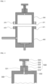
FIG. 1 is a cross-sectional view illustrating a gas collecting apparatus of the present disclosure. -
FIG. 2 is a cross-sectional view illustrating another embodiment of a gas collecting apparatus of the present disclosure. -
FIG. 3 is a cross-sectional view illustrating separated states of an upper housing and a lower housing. -
FIG. 4 is a detailed view illustrating a punching portion. -
FIG. 5 is a detailed view illustrating a button portion. -
FIG. 6 is a perspective view illustrating an upper jig and a lower jig. - A gas collecting apparatus of the present disclosure may include
- a lower jig in which a battery insertion groove into which a lower end of a battery is inserted is formed on an upper surface so that an upper end of the battery protrudes;
- an upper jig having a lower surface in close contact with the upper surface of the lower jig and a battery insertion hole into which the battery is inserted so that an upper surface of the battery is exposed;
- a lower housing configured to accommodate the lower jig therein; and
- an upper housing configured to accommodate the upper jig therein and having a lower end coupled to an upper end of the lower housing.
- On a ceiling surface of the upper housing in the gas collecting apparatus of the present disclosure, a punching portion configured to form a gas discharge hole by perforating an upper end of the battery may be provided.
- In the gas collecting apparatus of the present disclosure, a needle passage hole may be formed on an upper surface of the upper housing, and the punching portion may include a needle member inserted into the upper housing through the needle passage hole and having a lower end penetrating the upper end of the battery to form the gas discharge hole, a body member positioned above the upper housing and having a lower end coupled to an upper end of the needle member, a guide member coupled to an upper end of the upper housing and provided with a guide hole configured to guide a vertical movement of the body member, a pressing member coupled to an upper end of the body member that protrudes toward the upper end of the guide member, and an elastic member inserted between a lower end of the pressing member and an upper end of the guide member.
- In the gas collecting apparatus of the present disclosure, a button portion configured to press a lower end of the lower jig to push up the lower jig may be provided on a bottom surface of the lower housing.
- In the gas collecting apparatus of the present disclosure, an ascending member insertion hole may be formed on a lower surface of the lower housing, and the button portion may include a support member whose upper surface is in contact with a lower surface of the lower jig in the lower housing to support the lower jig, and an ascending member having an upper end coupled to a lower surface of the support member and a lower end protruding more downward than a lower end of the lower housing through the ascending member insertion hole.
- The support member of the gas collecting apparatus of the present disclosure may be provided in a disc shape that has a plane perpendicular to a vertical direction, the ascending member is provided in a cylindrical shape that extends in the vertical direction, and a diameter of the support member may be formed to be greater than that of the ascending member.
- In the gas collecting apparatus of the present disclosure, a support member insertion groove into which the support member is inserted may be formed on the bottom surface of the lower housing.
- A gas discharge pipe configured to discharge gas generated in the battery may be connected to the lower housing in the gas collecting apparatus of the present disclosure.
- In the gas collecting apparatus of the present disclosure, a first flow path may be formed in the upper jig, a second flow path may be formed in the lower jig, and gas discharged from the battery through the gas discharge hole may be transferred to the gas discharge pipe through the first flow path and the second flow path.
- In the gas collecting apparatus of the present disclosure, an upper surface of the upper jig may be spaced apart from the ceiling surface of the upper housing, the first flow path may be formed as a first gas discharge groove that extends in a vertical direction on an outer circumferential surface of the upper jig, and the second flow path may be formed as a second gas discharge groove that extends in the vertical direction on an outer circumferential surface of the lower jig.
- In the gas collecting apparatus of the present disclosure, a flow path connection groove may be formed in a ring shape along an outer circumferential surface on a lower end of the upper jig or an upper end of the lower jig.
- A jig for a gas collecting apparatus of the present disclosure may include
- an upper jig provided in a cylindrical shape that extends in a vertical direction; and
- a lower jig having an upper end coupled to a lower end of the upper jig, and
- wherein a battery insertion hole into which an upper end of a cylindrical battery is inserted may be formed in the upper jig,
- the battery insertion hole may be formed in a cylindrical shape that extends in the vertical direction,
- the cylindrical battery is inserted so that its outer circumferential surface is in close contact with an inner circumferential surface of the battery insertion hole,
- a battery insertion groove into which a lower end of the cylindrical battery is inserted may be formed on an upper surface of the lower jig,
- the battery insertion groove may be provided in a cylindrical shape that extends in a vertical direction,
- the cylindrical battery is inserted so that its outer circumferential surface is in close contact with an inner circumferential surface of the battery insertion groove,
- a first gas discharge groove that extends in the vertical direction may be formed on an outer circumferential surface of the upper jig, and
- a second gas discharge groove that extends in the vertical direction may be formed on an outer circumferential surface of the lower jig.
- In the jig for a gas collecting apparatus of the present disclosure, the first gas discharge groove may extend from an upper end to the lower end of the upper jig, and an upper end of the second gas discharge groove may be positioned on the upper end of the lower jig.
- In the jig for a gas collecting apparatus of the present disclosure, a ring-shaped third gas discharge groove that is formed along an outer circumferential surface of the lower jig may be formed, and a lower end of the second gas discharge groove may be connected to the third gas discharge groove.
- In the jig for a gas collecting apparatus of the present disclosure, a flow path connection groove may be formed in a ring shape along an outer circumferential surface on the lower end of the upper jig, and a lower end of the first gas discharge groove may be connected to the flow path connection groove.
- In the jig for a gas collecting apparatus of the present disclosure, a flow path connection groove may be formed in the ring shape along an outer circumferential surface on the upper end of the lower jig, and an upper end of the second gas discharge groove may be connected to the flow path connection groove.
- Hereinafter, example embodiments according to the present disclosure will be described in detail with reference to the accompanying drawings. In this process, the size or shape of components shown in the drawings may be exaggerated for clarity and convenience of explanation. In addition, terms specifically defined in consideration of configurations and operations of the present disclosure may vary depending on the intention or custom of a user or operator. Definitions of these terms should be made based on the context throughout this specification.
- In the description of the present disclosure, it should be noted that orientation or positional relationships indicated by the terms such as "center", "upper", "lower", "left", "right", "vertical", "horizontal", "inside", "outside", "one side", and "the other side" are based on orientation or positional relationships shown in the drawings or orientation or positional relationships usually of disposition when a product of the present disclosure is used, are merely for the description and brief illustration of the present disclosure, and should not be construed as limiting the present disclosure because they are not suggesting or implying that the indicated apparatus or element must be configured or operated in the specified orientation with the specified orientation.
-
FIG. 1 is a cross-sectional view illustrating a gas collecting apparatus of the present disclosure.FIG. 2 is a cross-sectional view illustrating another embodiment of the gas collecting apparatus of the present disclosure.FIG. 3 is a cross-sectional view illustrating separated states of anupper housing 300 and alower housing 400.FIG. 4 is a detailed view illustrating a punchingportion 500.FIG. 5 is a detailed view illustrating abutton portion 600.FIG. 6 is a perspective view illustrating anupper jig 100 and alower jig 200. - Hereinafter, with reference to
FIGS. 1 to 6 , the gas collecting apparatus of the present disclosure will be described in detail. - The gas collecting apparatus of the present disclosure may be applied to a cylindrical battery, a prismatic battery, a coin-type battery that has a case made of a rigid material and especially optimized for the cylindrical battery.
- The gas collecting apparatus of the present disclosure may be configured to perforate a
battery 11 in a closed space, diffuse gas generated inside thebattery 11 and discharged therefrom into the closed space, and then deliver the gas to a separate gas collection container or to a gas analyzer. - As shown in
FIG. 1 , the gas collecting apparatus of the present disclosure may include - the
lower jig 200 in which abattery insertion groove 210 into which a lower end of thebattery 11 is inserted is formed on an upper surface so that an upper end of thebattery 11 protrudes; - the
upper jig 100 having a lower surface in close contact with the upper surface of thelower jig 200 and abattery insertion hole 110 into which thebattery 11 is inserted so that an upper surface of thebattery 11 is exposed; - the
lower housing 400 configured to accommodate thelower jig 200 therein; and - the
upper housing 300 configured to accommodate theupper jig 100 therein and having a lower end coupled to an upper end of thelower housing 400. - In other words, the gas collecting apparatus of the present disclosure may be configured to accommodate the
battery 11, in which theupper jig 100 and thelower jig 200 are mounted, in a closed space that is formed by coupling of theupper housing 300 and thelower housing 400, and collect gas generated from thebattery 11. - As shown in
FIGS. 1 and 2 , even if a size of the battery that is subjected to gas collection changes, by mounting theupper jig 100 and thelower jig 200 corresponding to specifications of the battery to thebattery 11, it is possible to have thebattery 11 positioned in place inside the closed space that is formed by theupper housing 300 and thelower housing 400. In addition, in accordance with changes in the specifications of thebattery 11, it is also possible to constantly maintain concentration of exhaust gas due to changes in a volume occupied by thebattery 11 inside the closed space that is formed by theupper housing 300 and thelower housing 400. - The
upper jig 100 and thelower jig 200 may be made of a Teflon material that has a small coefficient of friction and exhibits superior chemical resistance and heat resistance. For example, theupper jig 100 and thelower jig 200 may be in cylindrical shapes extending in a vertical direction. - In the
upper jig 100, thebattery insertion hole 110 into which thebattery 11 is inserted may be formed. Thebattery insertion hole 110 may also be formed in a cylindrical shape that extends in the vertical direction, and an inner diameter of thebattery insertion hole 110 may be identical to an outer diameter of thebattery 11, thereby bringing an inner circumferential surface of thebattery insertion hole 110 into completely close contact with an outer circumferential surface of thebattery 11. In other words, theupper jig 100 may be formed in a form of a cylindrical pipe having an outer diameter of thebattery 11 as an inner diameter. Therefore, while theupper jig 100 is mounted on thebattery 11, thebattery 11 may be in a state in which an upper end and a lower end are exposed. - On an upper surface of the
lower jig 200, thebattery insertion groove 210 into which thebattery 11 is inserted may be formed. Thebattery insertion groove 210 may also be provided in a cylindrical shape that extends in the vertical direction to correspond to a shape of thebattery 11. An inner diameter of thebattery insertion groove 210 may also be formed to be identical to an outer diameter of thebattery 11, thereby brining an outer circumferential surface of thebattery 11 into completely close contact with an inner circumferential surface of thebattery insertion groove 210. - In other words, when the
upper jig 100 and thelower jig 200 are mounted on thebattery 11, theupper jig 100 may be mounted in a form of surrounding an upper portion of a side of thebattery 11, and a lower end of thebattery 11 protruding more downward than a lower end of theupper jig 100 may be inserted into thebattery insertion groove 210 of thelower jig 200. - The plurality of
upper jigs 100 andlower jigs 200 may be provided according to the types of thebattery 11 that is subjected to gas collection, and specifications of thebattery insertion hole 110 and thebattery insertion groove 210 may vary respectively depending on the types of thebattery 11. However, the outer diameter may be the same with respect to the plurality ofupper jigs 100 and the plurality oflower jigs 200, such that even if the types of thebattery 11 vary, a volume of a space in which the gas is discharged in the closed space formed by theupper housing 300 and thelower housing 400 may be the same. - As shown in
FIG. 3 , theupper housing 300 and thelower housing 400 may be formed with closed spaces which are configured to accommodate thebattery 11, theupper jig 100, and thelower jig 200 therein. The closed space may be provided in a cylindrical shape that extends in the vertical direction to correspond to outer circumferential surfaces of the cylindricalupper jig 100 andlower jig 200, and an upper part of the cylindrical closed space may be formed inside theupper jig 100, while a lower part of the closed space may be formed inside thelower jig 200. In other words, an inner space of theupper housing 300 may be in a state in which a lower side is open, and an upper inner space of thelower housing 400 is open. - The
upper housing 300 and thelower housing 400 may be formed of materials such as SUS which is a rigid, chemical resistant, and heat resistant material, so that the closed space may maintain a constant volume even with changes in internal pressure. The outer circumferential surfaces of theupper jig 100 and thelower jig 200 may come in completely close contact with inner circumferential surfaces of theupper housing 300 and thelower housing 400. - The sum of vertical lengths of the
upper jig 100 and thelower jig 200 may be greater than a depth of the closed space that is formed inside thelower housing 400. - In the upper end of the
lower housing 400, a first sealing groove into which a first sealing member is inserted at a position that faces the lower end of theupper housing 300 may be formed. The first sealing member may be an O-ring, and the first sealing groove may be formed in a closed loop shape surrounding the closed space in which thebattery 11 is accommodated. - As shown in
FIG. 3 , on each of the lower end of theupper housing 300 and the upper end of thelower housing 400, afirst protrusion 370 and asecond protrusion 470 protruding in a radial direction may be formed, respectively. In each of thefirst protrusion 370 and thesecond protrusion 470, a first fixingmember insertion hole 371 and a second fixingmember insertion hole 471 into which a fixing member for coupling between theupper housing 300 and thelower housing 400 is inserted may be formed, respectively. The first fixingmember insertion hole 371 and the second fixingmember insertion hole 471 may be formed in a position facing each other, and the fixing member may penetrate the first fixingmember insertion hole 371 and the second fixingmember insertion hole 471 at the same time to couple theupper housing 300 and thelower housing 400. For example, the fixing member may be a bolt, and a thread may be formed on one of inner circumferential surfaces of the first fixingmember insertion hole 371 and the second fixingmember insertion hole 471 to form a screw bonding with the fixing member. - In the gas collecting apparatus of the present disclosure, a punching
portion 500 configured to form a gas discharge hole by perforating an upper end of thebattery 11 may be provided on a ceiling surface of theupper housing 300. - A
needle passage hole 350 may be formed on an upper surface of theupper housing 300, and aneedle member 510 of the punchingportion 500 may be inserted into theupper housing 300 through theneedle passage hole 350 to perforate the upper end of thebattery 11. The perforated hole may be a gas discharge hole functioning as a passage for gas inside thebattery 11 to be discharged to the outside of thebattery 11. - As shown in
FIG. 4 , the punchingportion 500 may include - the
needle member 510 inserted into theupper housing 300 through theneedle passage hole 350 and having a lower end penetrating the upper end of thebattery 11 to form the gas discharge hole, - a
body member 520 positioned above theupper housing 300 and having a lower end coupled with an upper end of theneedle member 510, - a
guide member 530 coupled to the upper end of theupper housing 300 and formed with aguide hole 531 configured to guide a vertical movement of thebody member 520, - a
pressing member 540 coupled to an upper end of thebody member 520 protruding toward an upper end of theguide member 530, and - an
elastic member 550 inserted between a lower end of thepressing member 540 and the upper end of theguide member 530. - The
needle member 510 may have a lower end protruding from a ceiling surface inside theupper housing 300 to perforate the upper end of thebattery 11. - The
body member 520 may be formed in a rod shape extending in the vertical direction and configured to operate theneedle member 510 coupled to a lower end while moving vertically. - The
guide member 530 may be coupled to an upper end of theupper housing 300, and aguide hole 531 penetrated in the vertical direction may be formed. Thebody member 520 may be inserted into theguide hole 531 to guide a vertical movement. In theguide hole 531, a second sealing groove into which a second sealing member is inserted may be formed. The second sealing member may be an O-ring and positioned in a shape surrounding thebody member 520. The second sealing groove may also be provided in a shape of closed loop surrounding thebody member 520. - The pressing
member 540 may be provided in a disc shape having a diameter greater than that of thebody member 520, and an upper end of thebody member 520 may be coupled to a center of a lower surface of thepressing member 540. - The
elastic member 550 may have a lower end supported on an upper end of theguide member 530 and an upper end supported on a lower surface of thepressing member 540 and may be formed of an elastic material having resilience. Specifically, theelastic member 550 may be provided in a shape of cylindrical spring, and thebody member 520 may be inserted into a center of theelastic member 550. Theelastic member 550 may allow theneedle member 510 to automatically retreat after forming the gas discharge hole in thebattery 11. - As shown in
FIG. 5 , abutton portion 600 configured to press a lower end of thelower jig 200 to push up thelower jig 200 may be provided on a bottom surface of thelower housing 400. Thebutton portion 600 may be configured to lift thelower jig 200 and thebattery 11 so as to easily remove thelower jig 200 from the gas collecting apparatus at the end of gas collection. In other words, the upper end of thelower jig 200 may be positioned higher than the upper end of thelower housing 400 through thebutton portion 600, and a user may easily separate thelower jig 200 from thelower housing 400 through thebutton portion 600. For example, an outer circumferential surface of thelower jig 200 and an inner circumferential surface of thelower housing 400 may be in completely close contact, and thelower jig 200 may be easily discharged from thelower housing 400 through thebutton portion 600. - In the gas collecting apparatus of the present disclosure, a plurality of the
upper jigs 100 and thelower jigs 200 may be provided to correspond to the specifications of the battery that vary according to various types of the battery. Analysis conducted on each battery may be performed for a singleupper housing 300 andlower housing 400, by selecting one that is suitable for thebattery 11 to be analyzed from among the plurality ofupper jigs 100 andlower jigs 200, and assembling thebattery 11, theupper jig 100, thelower jig 200, theupper housing 300, and thelower housing 400. In this case, the gas collecting apparatus of the present disclosure may make separation between thelower jig 200 and thelower housing 400 easy by means of thebutton portion 600 when it comes to replacement of theupper jig 100 and thelower jig 200 for gas collection of the battery having another specification. - As shown in
FIG. 5 , an ascendingmember insertion hole 450 may be formed on the lower surface of thelower housing 400, and thebutton portion 600 may be inserted into the ascendingmember insertion hole 450, such that an upper end may be positioned inside thelower housing 400, and the lower end outside thelower housing 400. Therefore, by operation from the outside of the gas collecting apparatus, a force for separating thebattery 11 positioned inside the gas collecting apparatus may be applied to thebattery 11. - Specifically, the
button portion 600 may include - a
support member 610 whose upper surface is in contact with a lower surface of thelower jig 200 in thelower housing 400 to support thelower jig 200, and - an ascending
member 620 having an upper end coupled to a lower surface of thesupport member 610 and a lower end protruding more downward than the lower end of thelower housing 400 through the ascendingmember insertion hole 450. - More specifically, the
support member 610 may be provided in a disc shape that has a plane perpendicular to a vertical direction, the ascendingmember 620 may be provided in a cylindrical shape that extends in the vertical direction, and a diameter of thesupport member 610 may be greater than that of the ascendingmember 620. In other words, with the above structure, it is possible to prevent leakage by minimizing an inner diameter of the ascendingmember insertion hole 450 of thelower housing 400 and make thesupport member 610 stably lift thelower jig 200 by increasing an area of thesupport member 610 that is in contact with thelower jig 200. - In this case, a support
member insertion groove 460 into which thesupport member 610 is inserted may be formed on the bottom surface of thelower housing 400 so that the lower surface of thelower jig 200 comes in completely close contact with a bottom surface inside thelower housing 400. Therefore, thesupport member 610 may be completely embedded so as to prevent protrusion from the bottom surface inside thelower housing 400 through the supportmember insertion groove 610, thereby preventing formation of an unnecessary diffusion space between a lower surface of thelower jig 200 and the bottom surface inside thelower housing 400. - A
support bracket 700 configured to make the lower surface of thelower housing 400 separated from an installation surface of the gas collecting apparatus may be provided on the lower end of thelower housing 400. Thus, the lower end of the ascendingmember 620 may not come in contact with the installation surface. - A
gas discharge pipe 410 configured to discharge gas generated in thebattery 11 may be connected to thelower housing 400. - In this case, since gas generated in the
battery 11 may be discharged to the gas discharge hole formed at an upper end of thebattery 11, a flow path for connecting the gas discharge hole and thegas discharge pipe 410 may be required. - Accordingly, a first flow path may be formed in the
upper jig 100, a second flow path may be formed in thelower jig 200, and the gas discharged from thebattery 11 through the gas discharge hole may be transferred to thegas discharge pipe 410 through the first flow path and the second flow path. - As shown in
FIG. 1 , an upper surface of theupper jig 100 may be spaced apart from the ceiling surface of theupper housing 300, and as shown inFIG. 6 , the first flow path may be formed as a firstgas discharge groove 140 extending in the vertical direction on an outer circumferential surface of theupper jig 100, while the second flow path may be formed as a secondgas discharge groove 240 extending in the vertical direction on an outer circumferential surface of thelower jig 200. The firstgas discharge groove 140 extends from the upper end to the lower end of theupper jig 100, and the secondgas discharge groove 240 extends from the upper end of thelower jig 200 to a height of thegas discharge pipe 410. - In this case, ring-shaped flow
path connection grooves upper jig 100 or an upper end of thelower jig 200, such that gas may be transferred to thegas discharge pipe 410 through the flowpath connection grooves gas discharge groove 140 and an upper end of the secondgas discharge groove 240 do not exactly face each other. - A ring-shaped third
gas discharge groove 260 that is formed along an outer circumferential surface of thelower jig 200 may be formed in thelower jig 200, and a lower end of the secondgas discharge groove 240 may be connected to the thirdgas discharge groove 260. Therefore, when inserting thelower jig 200 into thelower housing 400, gas may be stably discharged through the thirdgas discharge groove 260 even when no additional alignment is performed. - Although the example embodiments according to the present disclosure have been described above, these are merely exemplary, and those skilled in the art will understand that various modifications and equivalent ranges of the example embodiments are possible therefrom. Accordingly, the scope for true technical protection of the present disclosure should be defined by the appended claims.
-
- 11...
Battery 100...Upperjig - 110...
Battery insertion hole 140...First gas discharge groove - 150, 250...Flow
path connection groove 200...Lower Jig - 210...
Battery insertion hole 240...Second gas discharge groove - 260...Third
gas discharge groove 300...Upper housing - 350...
Needle passage hole 370...First protrusion - 371...First fixing
member insertion hole 400...Lower housing - 410...
Gas discharge pipe 450...Ascending member insertion hole - 460...Support
member insertion groove 470... Second protrusion - 471...Second fixing
member insertion hole 500...Punching portion - 510 ...
Needle member 520...Body member - 530...
Guide member 531...Guide hole - 540...Pressing
member 550...Elastic member - 600...
Button portion 610... Support member - 620...Ascending
member 700... Support bracket - A gas collecting apparatus of the present disclosure is capable of collecting high-concentration gas for various batteries, while it is easy to mount, replace, or remove the battery at the beginning and end of analysis.
Claims (16)
- A gas collecting apparatus, comprising:a lower jig in which a battery insertion groove into which a lower end of a battery is inserted is formed on an upper surface so that an upper end of the battery protrudes;an upper jig having a lower surface in close contact with the upper surface of the lower jig and a battery insertion hole into which the battery is inserted so that an upper surface of the battery is exposed;a lower housing configured to accommodate the lower jig therein; andan upper housing configured to accommodate the upper jig therein and having a lower end coupled to an upper end of the lower housing.
- The gas collecting apparatus of claim 1, wherein, on a ceiling surface of the upper housing, a punching portion configured to form a gas discharge hole by perforating the upper end of the battery is provided.
- The gas collecting apparatus of claim 2, wherein a needle passage hole is formed on an upper surface of the upper housing, and
the punching portion comprises:a needle member inserted into the upper housing through the needle passage hole and having a lower end penetrating the upper end of the battery to form the gas discharge hole;a body member positioned above the upper housing and having a lower end coupled to an upper end of the needle member;a guide member coupled to an upper end of the upper housing and provided with a guide hole configured to guide a vertical movement of the body member;a pressing member coupled to an upper end of the body member that protrudes toward an upper end of the guide member; andan elastic member inserted between a lower end of the pressing member and the upper end of the guide member. - The gas collecting apparatus of claim 1, wherein a button portion configured to press a lower end of the lower jig to push up the lower jig is provided on a bottom surface of the lower housing.
- The gas collecting apparatus of claim 4, wherein an ascending member insertion hole is formed on a lower surface of the lower housing, and
the button portion comprises:a support member whose upper surface is in contact with a lower surface of the lower jig in the lower housing to support the lower jig; andan ascending member having an upper end coupled to a lower surface of the support member and a lower end protruding more downward than a lower end of the lower housing through the ascending member insertion hole. - The gas collecting apparatus of claim 5, wherein the support member is provided in a disc shape that has a plane perpendicular to a vertical direction,the ascending member is provided in a cylindrical shape that extends in the vertical direction, anda diameter of the support member is formed to be greater than that of the ascending member.
- The gas collecting apparatus of claim 6, wherein a support member insertion groove into which the support member is inserted is formed on the bottom surface of the lower housing.
- The gas collecting apparatus of claim 2, wherein a gas discharge pipe configured to discharge gas generated in the battery is connected to the lower housing.
- The gas collecting apparatus of claim 8, wherein a first flow path is formed in the upper jig,a second flow path is formed in the lower jig, andthe gas discharged from the battery through the gas discharge hole is transferred to the gas discharge pipe through the first flow path and the second flow path.
- The gas collecting apparatus of claim 9, wherein an upper surface of the upper jig is spaced apart from the ceiling surface of the upper housing,the first flow path is formed as a first gas discharge groove that extends in a vertical direction on an outer circumferential surface of the upper jig, andthe second flow path is formed as a second gas discharge groove that extends in the vertical direction on an outer circumferential surface of the lower jig.
- The gas collecting apparatus of claim 10, wherein a flow path connection groove is formed in a ring shape along an outer circumferential surface on a lower end of the upper jig or an upper end of the lower jig.
- A jig for a gas collecting apparatus, the jig comprising:an upper jig provided in a cylindrical shape that extends in a vertical direction; anda lower jig having an upper end coupled to a lower end of the upper jig, andwherein a battery insertion hole into which an upper end of a cylindrical battery is inserted is formed in the upper jig,the battery insertion hole is formed in a cylindrical shape that extends in the vertical direction,the cylindrical battery is inserted so that its outer circumferential surface is in close contact with an inner circumferential surface of the battery insertion hole,a battery insertion groove into which a lower end of the cylindrical battery is inserted is formed on an upper surface of the lower jig,the battery insertion groove is provided in a cylindrical shape that extends in the vertical direction,the cylindrical battery is inserted so that its outer circumferential surface is in close contact with an inner circumferential surface of the battery insertion groove,a first gas discharge groove that extends in the vertical direction is formed on an outer circumferential surface of the upper jig, anda second gas discharge groove that extends in the vertical direction is formed on an outer circumferential surface of the lower jig.
- The jig of claim 12, wherein the first gas discharge groove extends from an upper end to the lower end of the upper jig, and
an upper end of the second gas discharge groove is positioned on the upper end of the lower jig. - The jig of claim 13, wherein a ring-shaped third gas discharge groove that is formed along an outer circumferential surface of the lower jig is formed, and
a lower end of the second gas discharge groove is connected to the third gas discharge groove. - The jig of claim 13, wherein a flow path connection groove is formed in a ring shape along an outer circumferential surface on the lower end of the upper jig, and
a lower end of the first gas discharge groove is connected to the flow path connection groove. - The jig of claim 13, wherein a flow path connection groove is formed in a ring shape along an outer circumferential surface on the upper end of the lower jig, and
an upper end of the second gas discharge groove is connected to the flow path connection groove.
Applications Claiming Priority (2)
| Application Number | Priority Date | Filing Date | Title |
|---|---|---|---|
| KR1020210186715A KR20230097324A (en) | 2021-12-24 | 2021-12-24 | Apparatus for collecting gas |
| PCT/KR2022/015455 WO2023120910A1 (en) | 2021-12-24 | 2022-10-13 | Gas collection device |
Publications (1)
| Publication Number | Publication Date |
|---|---|
| EP4297168A1 true EP4297168A1 (en) | 2023-12-27 |
Family
ID=86902828
Family Applications (1)
| Application Number | Title | Priority Date | Filing Date |
|---|---|---|---|
| EP22911549.8A Pending EP4297168A1 (en) | 2021-12-24 | 2022-10-13 | Gas collection device |
Country Status (6)
| Country | Link |
|---|---|
| US (1) | US20240204350A1 (en) |
| EP (1) | EP4297168A1 (en) |
| JP (1) | JP2024518814A (en) |
| KR (1) | KR20230097324A (en) |
| CN (1) | CN117203842A (en) |
| WO (1) | WO2023120910A1 (en) |
Family Cites Families (5)
| Publication number | Priority date | Publication date | Assignee | Title |
|---|---|---|---|---|
| KR101979594B1 (en) * | 2015-10-06 | 2019-05-17 | 주식회사 엘지화학 | Apparatus to collect inner gas for small circular lithium-ion battery |
| KR101989909B1 (en) * | 2015-10-06 | 2019-06-17 | 주식회사 엘지화학 | A device for collecting inner gas in secondary battery and charging/discharging in secondary battery |
| KR102145107B1 (en) * | 2018-04-12 | 2020-08-14 | 주식회사 엘지화학 | Apparatus for collecting inner gas in secondary electric cell and method thereof |
| KR20210103764A (en) * | 2020-02-14 | 2021-08-24 | 주식회사 엘지화학 | Apparatus for collecting cell internal gas |
| KR20210125283A (en) * | 2020-04-08 | 2021-10-18 | (주)이손 | Apparatus for analyzing real gas in secondary battery |
-
2021
- 2021-12-24 KR KR1020210186715A patent/KR20230097324A/en unknown
-
2022
- 2022-10-13 EP EP22911549.8A patent/EP4297168A1/en active Pending
- 2022-10-13 JP JP2023558847A patent/JP2024518814A/en active Pending
- 2022-10-13 US US18/287,452 patent/US20240204350A1/en active Pending
- 2022-10-13 WO PCT/KR2022/015455 patent/WO2023120910A1/en active Application Filing
- 2022-10-13 CN CN202280027632.XA patent/CN117203842A/en active Pending
Also Published As
| Publication number | Publication date |
|---|---|
| JP2024518814A (en) | 2024-05-07 |
| WO2023120910A1 (en) | 2023-06-29 |
| KR20230097324A (en) | 2023-07-03 |
| CN117203842A (en) | 2023-12-08 |
| US20240204350A1 (en) | 2024-06-20 |
Similar Documents
| Publication | Publication Date | Title |
|---|---|---|
| EP3696902A1 (en) | Apparatus and method for collecting gas | |
| EP3809512A1 (en) | Secondary-battery internal gas collecting apparatus | |
| KR102541798B1 (en) | End cover assembly, secondary battery, battery pack and device using battery | |
| JP5241182B2 (en) | Assembled battery | |
| KR20070103890A (en) | Pressure-discharged venting system for rechargable battery | |
| KR20210103764A (en) | Apparatus for collecting cell internal gas | |
| EP4297168A1 (en) | Gas collection device | |
| KR20180047280A (en) | Apparatus for collecting inner gas in secondary electric cell and method thereof | |
| KR102154900B1 (en) | Apparatus for collecting inner gas in secondary electric cell and method thereof | |
| WO2005060034A3 (en) | Fuel cell and fuel cell stack | |
| KR102145107B1 (en) | Apparatus for collecting inner gas in secondary electric cell and method thereof | |
| EP3813180A1 (en) | Secondary-battery internal gas collecting apparatus | |
| KR20230000625A (en) | Apparatus for collecting gas | |
| EP4397953A1 (en) | Gas collection device | |
| EP4414683A1 (en) | Gas collection device | |
| CN220873648U (en) | Auxiliary device for battery assembly | |
| EP4432421A1 (en) | Gas collection device | |
| CN114243169B (en) | Zinc-air battery shell structure | |
| EP4411910A1 (en) | Secondary battery manufacturing method, gas discharge and electrolyte injection mechanism, and secondary battery including same | |
| EP4220111A1 (en) | Apparatus for analyzing battery case | |
| KR20240018805A (en) | Tube device for collecting gas | |
| KR20230047581A (en) | Cylindrical Battery Cell Disassembly Jig |
Legal Events
| Date | Code | Title | Description |
|---|---|---|---|
| STAA | Information on the status of an ep patent application or granted ep patent |
Free format text: STATUS: THE INTERNATIONAL PUBLICATION HAS BEEN MADE |
|
| PUAI | Public reference made under article 153(3) epc to a published international application that has entered the european phase |
Free format text: ORIGINAL CODE: 0009012 |
|
| STAA | Information on the status of an ep patent application or granted ep patent |
Free format text: STATUS: REQUEST FOR EXAMINATION WAS MADE |
|
| 17P | Request for examination filed |
Effective date: 20230920 |
|
| AK | Designated contracting states |
Kind code of ref document: A1 Designated state(s): AL AT BE BG CH CY CZ DE DK EE ES FI FR GB GR HR HU IE IS IT LI LT LU LV MC ME MK MT NL NO PL PT RO RS SE SI SK SM TR |