EP4297163A1 - Battery module - Google Patents
Battery module Download PDFInfo
- Publication number
- EP4297163A1 EP4297163A1 EP23179174.0A EP23179174A EP4297163A1 EP 4297163 A1 EP4297163 A1 EP 4297163A1 EP 23179174 A EP23179174 A EP 23179174A EP 4297163 A1 EP4297163 A1 EP 4297163A1
- Authority
- EP
- European Patent Office
- Prior art keywords
- plate
- battery module
- cell stacks
- crossbeam
- wedge
- Prior art date
- Legal status (The legal status is an assumption and is not a legal conclusion. Google has not performed a legal analysis and makes no representation as to the accuracy of the status listed.)
- Pending
Links
- 238000005192 partition Methods 0.000 claims description 20
- 239000000853 adhesive Substances 0.000 claims description 6
- 230000001070 adhesive effect Effects 0.000 claims description 6
- 230000007246 mechanism Effects 0.000 claims description 5
- 238000003825 pressing Methods 0.000 claims description 2
- 238000000034 method Methods 0.000 abstract description 10
- 230000008569 process Effects 0.000 abstract description 9
- 230000004075 alteration Effects 0.000 description 2
- 239000003292 glue Substances 0.000 description 2
- 230000013011 mating Effects 0.000 description 2
- 230000008961 swelling Effects 0.000 description 2
- 230000032677 cell aging Effects 0.000 description 1
- 238000001816 cooling Methods 0.000 description 1
- 125000004122 cyclic group Chemical group 0.000 description 1
- 238000007599 discharging Methods 0.000 description 1
- 238000005516 engineering process Methods 0.000 description 1
- 230000010354 integration Effects 0.000 description 1
- 230000002093 peripheral effect Effects 0.000 description 1
- 238000005070 sampling Methods 0.000 description 1
- 230000007480 spreading Effects 0.000 description 1
- 238000003466 welding Methods 0.000 description 1
Images


Classifications
-
- H—ELECTRICITY
- H01—ELECTRIC ELEMENTS
- H01M—PROCESSES OR MEANS, e.g. BATTERIES, FOR THE DIRECT CONVERSION OF CHEMICAL ENERGY INTO ELECTRICAL ENERGY
- H01M50/00—Constructional details or processes of manufacture of the non-active parts of electrochemical cells other than fuel cells, e.g. hybrid cells
- H01M50/20—Mountings; Secondary casings or frames; Racks, modules or packs; Suspension devices; Shock absorbers; Transport or carrying devices; Holders
- H01M50/204—Racks, modules or packs for multiple batteries or multiple cells
-
- H—ELECTRICITY
- H01—ELECTRIC ELEMENTS
- H01M—PROCESSES OR MEANS, e.g. BATTERIES, FOR THE DIRECT CONVERSION OF CHEMICAL ENERGY INTO ELECTRICAL ENERGY
- H01M10/00—Secondary cells; Manufacture thereof
- H01M10/60—Heating or cooling; Temperature control
- H01M10/61—Types of temperature control
- H01M10/613—Cooling or keeping cold
-
- H—ELECTRICITY
- H01—ELECTRIC ELEMENTS
- H01M—PROCESSES OR MEANS, e.g. BATTERIES, FOR THE DIRECT CONVERSION OF CHEMICAL ENERGY INTO ELECTRICAL ENERGY
- H01M10/00—Secondary cells; Manufacture thereof
- H01M10/60—Heating or cooling; Temperature control
- H01M10/65—Means for temperature control structurally associated with the cells
- H01M10/655—Solid structures for heat exchange or heat conduction
- H01M10/6554—Rods or plates
-
- H—ELECTRICITY
- H01—ELECTRIC ELEMENTS
- H01M—PROCESSES OR MEANS, e.g. BATTERIES, FOR THE DIRECT CONVERSION OF CHEMICAL ENERGY INTO ELECTRICAL ENERGY
- H01M50/00—Constructional details or processes of manufacture of the non-active parts of electrochemical cells other than fuel cells, e.g. hybrid cells
- H01M50/20—Mountings; Secondary casings or frames; Racks, modules or packs; Suspension devices; Shock absorbers; Transport or carrying devices; Holders
- H01M50/233—Mountings; Secondary casings or frames; Racks, modules or packs; Suspension devices; Shock absorbers; Transport or carrying devices; Holders characterised by physical properties of casings or racks, e.g. dimensions
- H01M50/242—Mountings; Secondary casings or frames; Racks, modules or packs; Suspension devices; Shock absorbers; Transport or carrying devices; Holders characterised by physical properties of casings or racks, e.g. dimensions adapted for protecting batteries against vibrations, collision impact or swelling
-
- H—ELECTRICITY
- H01—ELECTRIC ELEMENTS
- H01M—PROCESSES OR MEANS, e.g. BATTERIES, FOR THE DIRECT CONVERSION OF CHEMICAL ENERGY INTO ELECTRICAL ENERGY
- H01M50/00—Constructional details or processes of manufacture of the non-active parts of electrochemical cells other than fuel cells, e.g. hybrid cells
- H01M50/20—Mountings; Secondary casings or frames; Racks, modules or packs; Suspension devices; Shock absorbers; Transport or carrying devices; Holders
- H01M50/289—Mountings; Secondary casings or frames; Racks, modules or packs; Suspension devices; Shock absorbers; Transport or carrying devices; Holders characterised by spacing elements or positioning means within frames, racks or packs
-
- H—ELECTRICITY
- H01—ELECTRIC ELEMENTS
- H01M—PROCESSES OR MEANS, e.g. BATTERIES, FOR THE DIRECT CONVERSION OF CHEMICAL ENERGY INTO ELECTRICAL ENERGY
- H01M50/00—Constructional details or processes of manufacture of the non-active parts of electrochemical cells other than fuel cells, e.g. hybrid cells
- H01M50/20—Mountings; Secondary casings or frames; Racks, modules or packs; Suspension devices; Shock absorbers; Transport or carrying devices; Holders
- H01M50/289—Mountings; Secondary casings or frames; Racks, modules or packs; Suspension devices; Shock absorbers; Transport or carrying devices; Holders characterised by spacing elements or positioning means within frames, racks or packs
- H01M50/291—Mountings; Secondary casings or frames; Racks, modules or packs; Suspension devices; Shock absorbers; Transport or carrying devices; Holders characterised by spacing elements or positioning means within frames, racks or packs characterised by their shape
-
- H—ELECTRICITY
- H01—ELECTRIC ELEMENTS
- H01M—PROCESSES OR MEANS, e.g. BATTERIES, FOR THE DIRECT CONVERSION OF CHEMICAL ENERGY INTO ELECTRICAL ENERGY
- H01M50/00—Constructional details or processes of manufacture of the non-active parts of electrochemical cells other than fuel cells, e.g. hybrid cells
- H01M50/20—Mountings; Secondary casings or frames; Racks, modules or packs; Suspension devices; Shock absorbers; Transport or carrying devices; Holders
- H01M50/204—Racks, modules or packs for multiple batteries or multiple cells
- H01M50/207—Racks, modules or packs for multiple batteries or multiple cells characterised by their shape
- H01M50/209—Racks, modules or packs for multiple batteries or multiple cells characterised by their shape adapted for prismatic or rectangular cells
-
- Y—GENERAL TAGGING OF NEW TECHNOLOGICAL DEVELOPMENTS; GENERAL TAGGING OF CROSS-SECTIONAL TECHNOLOGIES SPANNING OVER SEVERAL SECTIONS OF THE IPC; TECHNICAL SUBJECTS COVERED BY FORMER USPC CROSS-REFERENCE ART COLLECTIONS [XRACs] AND DIGESTS
- Y02—TECHNOLOGIES OR APPLICATIONS FOR MITIGATION OR ADAPTATION AGAINST CLIMATE CHANGE
- Y02E—REDUCTION OF GREENHOUSE GAS [GHG] EMISSIONS, RELATED TO ENERGY GENERATION, TRANSMISSION OR DISTRIBUTION
- Y02E60/00—Enabling technologies; Technologies with a potential or indirect contribution to GHG emissions mitigation
- Y02E60/10—Energy storage using batteries
Definitions
- the present utility model relates to the technical field of batteries, in particular to a battery module.
- a battery module generally has the characteristics of high voltage and high capacity, and must therefore comprise multiple cells.
- multiple cells are first stacked and pre-grouped, buses and sampling wiring harnesses are fitted by welding, the multiple cells are pre-connected electrically, pre-grouped cell stacks are formed, then the pre-grouped cell stacks are fixed to the bottom of a case directly using structural glue, thereby forming the battery module.
- the positioning, clamping and fixing of the cell stacks is generally achieved by bolt connection using end plate members of the battery module or the cell stacks.
- the connection of bolts and the end plate members of the battery module makes the assembly process step tedious, increases the weight of the battery module, and affects the energy density of the battery module.
- the cells undergo a cyclic process of charging and discharging, accompanied by cell ageing, so a swelling force will arise inside the cells.
- various wiring harnesses of the cells might develop the risk of damage to electrical connections due to deformation, breakage, etc.
- existing battery modules rely solely on sidewalls of the battery case to provide side anti-collision functionality, but adequate anti-collision performance generally cannot be provided. In the event of a side collision, there might be a potential risk of structural failure of the battery module.
- An objective of the present utility model is to provide an improved battery module, to simplify the assembly process of the battery module and increase the structural strength of the battery module.
- a battery module comprising: a case, comprising a first plate and a second plate opposite the first plate; and two cell stacks, each of the two cell stacks comprising multiple cells stacked in a stacking direction, and the two cell stacks being installed adjacent to each other in the stacking direction between the first plate and the second plate, wherein the battery module further comprises a crossbeam arranged between two adjacent ends of the two cell stacks, such that each of the two cell stacks is subjected to pressure from the crossbeam in the stacking direction.
- the case further comprises two side plates extending between the first plate and the second plate, the crossbeam being fixedly connected between the two side plates.
- the crossbeam has a wedge-shaped cross section, and the two ends each comprise a wedge-shaped part matching the wedge shape of the crossbeam, the crossbeam pressing against the wedge-shaped parts.
- the crossbeam has a symmetrical wedge-shaped cross section, and the two ends comprise wedge-shaped parts that are symmetrical with each other.
- the crossbeam is fixedly connected between the two side plates by bolts or snap-fit.
- the crossbeam and the wedge-shaped part are each made of a hollow profile.
- the case further comprises a bottom plate, the two cell stacks being adhered to the bottom plate by means of an adhesive.
- the bottom plate is provided with an opening, and the two cell stacks are arranged to correspond to the opening.
- At least one of the first plate, the second plate, the side plates and the bottom plate is made of a hollow profile.
- the battery module further comprises an additional plate arranged below the bottom plate.
- the case comprises two end plates and at least one partition plate arranged between the two side plates, the at least one partition plate being fixedly connected to the two side plates, the first plate and the second plate being two adjacent plates among the end plates and the at least one partition plate.
- the case further comprises a connecting plate arranged between the two end plates, the connecting plate being fixedly connected to the two end plates.
- the first plate and the second plate are further each provided with a bolt connection mechanism, configured to clamp and fix the two cell stacks and the crossbeam.
- the battery module of the present utility model uses the crossbeam to clamp and fix the cell stacks and provide protection for the battery module against lateral collision, the battery module can have a simpler assembly process and be more manufacturing-friendly, while the number of components can be reduced, thus lowering costs. Furthermore, the crossbeam can also increase the structural strength and safety of the battery module.
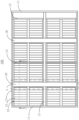
- a battery module 100 comprises a case 10, cell stacks 20 and crossbeams 30, wherein the cell stacks 20 are installed in the case 10, and each crossbeam 30 is arranged between adjacent ends of two adjacent cell stacks 20.
- Region A in Fig. 1 shows a position where a crossbeam 30 is located.
- Fig. 1 shows two crossbeams 30 and a total of 16 cell stacks combined as pairs, but the present utility model is not limited to the specific number of cell stacks 20 and crossbeams 30 shown, and may have a larger or smaller number of cell stacks 20 and crossbeams 30.
- the specific structures and assembly process of the case 10, the cell stacks 20 and the crossbeams 30 are described further below with reference to Figs. 2 - 5 .
- the case 10 comprises two end plates 11 and two side plates 13 extending between the two end plates 11, and a framework structure of the case 10 is thus formed.
- a partition plate 12 may also be provided between the two side plates 13, and a connecting plate 15 may also be provided between the two end plates 11, wherein the partition plate 12 is fixedly connected to the two side plates 13, and the connecting plate 15 is fixedly connected to the two end plates 11, to increase the structural strength of the case 10 and separate different cell stacks 20.
- the case 10 may also comprise a bottom plate, and the bottom plate 14 may be provided with openings.
- the present utility model is not limited to the case structure shown, and may comprise a larger or smaller number of partition plates 12 and connecting plates 15, or may even have no partition plate 12 and no connecting plate 15, and may also comprise other structural components such as a mounting plate or mounting seat, etc. for mounting an electronic device, or may omit a particular component in the case 10, for example may omit the side plates 13 and the bottom plate 14 of the case 10 when a peripheral mounting mechanism is able to provide lateral and bottom fixing and protection; the present utility model will not be described in further detail in this regard.
- each cell stack 20 comprising multiple cells 21 stacked together in a stacking direction, with adjacent cells 21 being joined together by an adhesive for example.
- Each cell 21 has a terminal, and the terminals of adjacent cells 21 are connected to each other, thereby forming pre-grouped cell stacks 20. It should be pointed out that the cells 21 may also form pre-grouped cell stacks 20 in another manner known in the art; the present utility model imposes no restrictions in this respect.
- the 16 cell stacks 20 are divided into 8 pairs, each pair comprising two cell stacks 20 adjacent to each other in the stacking direction. These cell stacks 20 may be installed in 4 spaces of the case 10 in the direction of the arrow shown in Fig. 3 , the spaces being separated by the end plates 11, the partition plate 12, the side plates 13 and the connecting plate 15.
- the cell stacks 20 may correspond to the openings in the bottom plate 14, so as to prevent heat from spreading to other cell stacks 20 when one cell stack 20 overheats or discharges gas.
- ends of two adjacent cell stacks 20 are further provided with wedge-shaped parts 22.
- the wedge-shaped parts 22 may be adhered to the ends of the cell stacks 20 by means of an adhesive. The wedge-shaped parts 22 will be further described below with reference to Figs. 4 and 5 .
- the crossbeam 30 has a wedge-shaped cross section and is disposed between the ends, provided with the wedge-shaped parts 22, of two adjacent cell stacks 20, wherein the shape of the wedge-shaped parts 22 matches the wedge shape of the cross section of the crossbeam 30.
- the crossbeam 30 may be inserted between the wedge-shaped parts 22 of adjacent cell stacks 20 as shown by the arrows in Fig. 4 .
- Figs. 4 and 5 only show the case where two cell stacks 20 are clamped and fixed using one crossbeam 30, but the present utility model is not limited to this.
- three, four or more cell stacks 20 may be arranged between a first plate and a second plate that are opposite each other, with one crossbeam 30 inserted between each pair of adjacent cell stacks 20, and this can likewise achieve the clamping and fixing of more than two cell stacks 20.
- the first plate and second plate may respectively be two adjacent plates among the end plates 11 and the partition plate 12 of the case 10.
- the first plate and second plate may be the two end plates 11, and in a case that comprises more than one partition plate 12, the first plate and second plate may respectively be two adjacent plates among the end plates 11 and the partition plates 12, for example, an end plate and a partition plate, a partition plate and a partition plate, or a partition plate and an end plate, respectively.
- the present utility model is not limited to the structure described above in which the wedge-shaped parts 22 of the cell stacks 20 match the wedge shape of the crossbeam 30, and can achieve protection of the battery module against lateral collision as well as clamping and fixing of the cell stacks without a wedge-shaped mating structure.
- lateral protection is provided by arranging a crossbeam between two adjacent cell stacks (with neither the cell stacks nor the crossbeam comprising a wedge-shaped structure), and the two cell stacks and the crossbeam are clamped together by providing a bolt connection mechanism (not shown) on each of the first plate and second plate, so as to clamp and fix the cell stacks.
- the abovementioned bolt connection mechanism may also be provided when a wedge-shaped mating structure is included, to further improve clamping and fixing of the cell stacks.
- the wedge shape of the cross section of the crossbeam 30 is a symmetrical shape, and the wedge-shaped parts 22 at the ends of the two adjacent cell stacks 20 are symmetrical with each other.
- the wedge shape of the cross section of the crossbeam 30 may also be asymmetrical, and correspondingly, the wedge-shaped parts 22 at the ends of the two adjacent cell stacks 20 may also be asymmetrical.
- the crossbeam 30 and the wedge-shaped parts 22 may each be made of a hollow profile, and one or more of the end plates 11, the side plates 13, the partition plate 12, the bottom plate 14 and the connecting plate 15 may also be made of a hollow profile; in this way, the weight of the battery module 100 can be reduced.
- an adhesive such as structural glue may be applied to the bottom plate 14 of the case 10 before the cell stacks 20 are installed in the case 10, for example, applied within the region B in Fig. 5 , such that the cell stacks 20 can be adhered to the bottom plate 14 by means of the adhesive.
- the battery module 100 may further comprise an additional plate 18 arranged below the bottom plate 14, for example, a cooling plate, an insulating plate, etc.
- the positioning, clamping and fixing of the cell stacks can be achieved in a single operation in the process of integration by means of the crossbeam and the wedge-shaped parts, making it simpler for the cell stacks to form the battery module; moreover, end plate members and bolt fasteners, etc. are avoided, so the number of components can be reduced, lowering costs, and the structural strength and safety of the battery module are increased.
Landscapes
- Chemical & Material Sciences (AREA)
- Chemical Kinetics & Catalysis (AREA)
- Electrochemistry (AREA)
- General Chemical & Material Sciences (AREA)
- Engineering & Computer Science (AREA)
- Manufacturing & Machinery (AREA)
- Battery Mounting, Suspending (AREA)
Abstract
Description
- The present utility model relates to the technical field of batteries, in particular to a battery module.
- As battery technology develops and more importance is attached to the utilization of new energy sources, battery modules are being used to an ever increasing extent as sources of motive power for various apparatuses, for example providing traction force in new energy vehicles. A battery module generally has the characteristics of high voltage and high capacity, and must therefore comprise multiple cells. In existing battery module assembly processes, generally, multiple cells are first stacked and pre-grouped, buses and sampling wiring harnesses are fitted by welding, the multiple cells are pre-connected electrically, pre-grouped cell stacks are formed, then the pre-grouped cell stacks are fixed to the bottom of a case directly using structural glue, thereby forming the battery module.
- In existing battery modules, the positioning, clamping and fixing of the cell stacks is generally achieved by bolt connection using end plate members of the battery module or the cell stacks. In this case, the connection of bolts and the end plate members of the battery module makes the assembly process step tedious, increases the weight of the battery module, and affects the energy density of the battery module.
- In addition, in the process of operation of the battery module, the cells undergo a cyclic process of charging and discharging, accompanied by cell ageing, so a swelling force will arise inside the cells. When the swelling force is significant, various wiring harnesses of the cells might develop the risk of damage to electrical connections due to deformation, breakage, etc. Furthermore, existing battery modules rely solely on sidewalls of the battery case to provide side anti-collision functionality, but adequate anti-collision performance generally cannot be provided. In the event of a side collision, there might be a potential risk of structural failure of the battery module.
- Thus, improvements need to be made to existing battery modules, to overcome at least one of the shortcomings in the prior art.
- An objective of the present utility model is to provide an improved battery module, to simplify the assembly process of the battery module and increase the structural strength of the battery module.
- To this end, according to one aspect of the present utility model, a battery module is provided, comprising: a case, comprising a first plate and a second plate opposite the first plate; and two cell stacks, each of the two cell stacks comprising multiple cells stacked in a stacking direction, and the two cell stacks being installed adjacent to each other in the stacking direction between the first plate and the second plate, wherein the battery module further comprises a crossbeam arranged between two adjacent ends of the two cell stacks, such that each of the two cell stacks is subjected to pressure from the crossbeam in the stacking direction.
- According to an embodiment of the present utility model, the case further comprises two side plates extending between the first plate and the second plate, the crossbeam being fixedly connected between the two side plates.
- According to an embodiment of the present utility model, the crossbeam has a wedge-shaped cross section, and the two ends each comprise a wedge-shaped part matching the wedge shape of the crossbeam, the crossbeam pressing against the wedge-shaped parts.
- According to an embodiment of the present utility model, the crossbeam has a symmetrical wedge-shaped cross section, and the two ends comprise wedge-shaped parts that are symmetrical with each other.
- According to an embodiment of the present utility model, the crossbeam is fixedly connected between the two side plates by bolts or snap-fit.
- According to an embodiment of the present utility model, the crossbeam and the wedge-shaped part are each made of a hollow profile.
- According to an embodiment of the present utility model, the case further comprises a bottom plate, the two cell stacks being adhered to the bottom plate by means of an adhesive.
- According to an embodiment of the present utility model, the bottom plate is provided with an opening, and the two cell stacks are arranged to correspond to the opening.
- According to an embodiment of the present utility model, at least one of the first plate, the second plate, the side plates and the bottom plate is made of a hollow profile.
- According to an embodiment of the present utility model, the battery module further comprises an additional plate arranged below the bottom plate.
- According to an embodiment of the present utility model, the case comprises two end plates and at least one partition plate arranged between the two side plates, the at least one partition plate being fixedly connected to the two side plates, the first plate and the second plate being two adjacent plates among the end plates and the at least one partition plate.
- According to an embodiment of the present utility model, the case further comprises a connecting plate arranged between the two end plates, the connecting plate being fixedly connected to the two end plates.
- According to an embodiment of the present utility model, the first plate and the second plate are further each provided with a bolt connection mechanism, configured to clamp and fix the two cell stacks and the crossbeam.
- Since the battery module of the present utility model uses the crossbeam to clamp and fix the cell stacks and provide protection for the battery module against lateral collision, the battery module can have a simpler assembly process and be more manufacturing-friendly, while the number of components can be reduced, thus lowering costs. Furthermore, the crossbeam can also increase the structural strength and safety of the battery module.
- Exemplary embodiments of the present utility model are described in detail below with reference to the drawings, but it should be understood that the embodiments described below are merely intended to explain the present utility model, without limiting the scope thereof. In the drawings:
-
Fig. 1 is a schematic top view of a battery module according to an exemplary embodiment of the present utility model. -
Fig. 2 is a schematic perspective drawing of the case of the battery module shown inFig. 1 . -
Fig. 3 is a schematic perspective drawing of the case and cell stacks of the battery module shown inFig. 1 , wherein the cell stacks are shown as being about to be installed in the case. -
Fig. 4 is a schematic perspective drawing of the case, cell stacks and crossbeams of the battery module shown inFig. 1 , wherein the cell stacks are shown as having been already installed in the case, and the crossbeams are shown as being about to be installed in the case. -
Fig. 5 is a schematic partial section taken along line C-C' inFig. 1 . - Preferred embodiments of the present utility model are described in detail below with reference to examples. However, those skilled in the art should understand that these exemplary embodiments do not signify any limitation of the present utility model. Furthermore, in the absence of conflict, features in embodiments of the present utility model may be combined with each other. In the drawings, other components have been omitted for conciseness, but this does not mean that the battery module of the present utility model cannot include other components.
- As shown in
Fig. 1 , abattery module 100 according to an exemplary embodiment of the present utility model comprises acase 10,cell stacks 20 andcrossbeams 30, wherein thecell stacks 20 are installed in thecase 10, and eachcrossbeam 30 is arranged between adjacent ends of twoadjacent cell stacks 20. Region A inFig. 1 shows a position where acrossbeam 30 is located. It should be pointed out thatFig. 1 shows twocrossbeams 30 and a total of 16 cell stacks combined as pairs, but the present utility model is not limited to the specific number ofcell stacks 20 andcrossbeams 30 shown, and may have a larger or smaller number ofcell stacks 20 andcrossbeams 30. The specific structures and assembly process of thecase 10, the cell stacks 20 and thecrossbeams 30 are described further below with reference toFigs. 2 - 5 . - As shown in
Fig. 2 , thecase 10 comprises twoend plates 11 and twoside plates 13 extending between the twoend plates 11, and a framework structure of thecase 10 is thus formed. Additionally, apartition plate 12 may also be provided between the twoside plates 13, and a connectingplate 15 may also be provided between the twoend plates 11, wherein thepartition plate 12 is fixedly connected to the twoside plates 13, and the connectingplate 15 is fixedly connected to the twoend plates 11, to increase the structural strength of thecase 10 and separatedifferent cell stacks 20. In addition, thecase 10 may also comprise a bottom plate, and thebottom plate 14 may be provided with openings. However, it should be pointed out that the present utility model is not limited to the case structure shown, and may comprise a larger or smaller number ofpartition plates 12 and connectingplates 15, or may even have nopartition plate 12 and no connectingplate 15, and may also comprise other structural components such as a mounting plate or mounting seat, etc. for mounting an electronic device, or may omit a particular component in thecase 10, for example may omit theside plates 13 and thebottom plate 14 of thecase 10 when a peripheral mounting mechanism is able to provide lateral and bottom fixing and protection; the present utility model will not be described in further detail in this regard. - 16
cell stacks 20 are shown inFig. 3 , eachcell stack 20 comprisingmultiple cells 21 stacked together in a stacking direction, withadjacent cells 21 being joined together by an adhesive for example. Eachcell 21 has a terminal, and the terminals ofadjacent cells 21 are connected to each other, thereby forming pre-groupedcell stacks 20. It should be pointed out that thecells 21 may also form pre-groupedcell stacks 20 in another manner known in the art; the present utility model imposes no restrictions in this respect. - As shown in
Fig. 3 , the 16cell stacks 20 are divided into 8 pairs, each pair comprising twocell stacks 20 adjacent to each other in the stacking direction. Thesecell stacks 20 may be installed in 4 spaces of thecase 10 in the direction of the arrow shown inFig. 3 , the spaces being separated by theend plates 11, thepartition plate 12, theside plates 13 and the connectingplate 15. Thecell stacks 20 may correspond to the openings in thebottom plate 14, so as to prevent heat from spreading toother cell stacks 20 when one cell stack 20 overheats or discharges gas. Furthermore, as shown inFig. 3 , ends of twoadjacent cell stacks 20 are further provided with wedge-shaped parts 22. The wedge-shaped parts 22 may be adhered to the ends of thecell stacks 20 by means of an adhesive. The wedge-shaped parts 22 will be further described below with reference toFigs. 4 and5 . - As shown in
Figs. 4 and5 , thecrossbeam 30 has a wedge-shaped cross section and is disposed between the ends, provided with the wedge-shaped parts 22, of twoadjacent cell stacks 20, wherein the shape of the wedge-shaped parts 22 matches the wedge shape of the cross section of thecrossbeam 30. Referring toFig. 4 , when thecell stacks 20 have been installed in thecase 10, thecrossbeam 30 may be inserted between the wedge-shaped parts 22 ofadjacent cell stacks 20 as shown by the arrows inFig. 4 . In the process of pushing thecrossbeam 30 downwards, and as thecrossbeam 30 presses against the wedge-shaped parts 22, a compressive force exerted in the stacking direction arises; as a result, the twocell stacks 20 are subjected to pressure from thecrossbeam 30 in the stacking direction, and thecell stacks 20 can thus be clamped and fixed. Thecrossbeam 30 can then be fixedly connected to theside plates 13 of thecase 10 by screws or snap-fit (not shown), etc. thereby providing the battery module with protection against lateral collision, so as to maintain the structural integrity of the battery module during lateral collision. A wiring harness of eachcell stack 20 can then be connected to an electronic device and a bus arranged on thecase 10, so as to form thebattery module 100 for supplying power to the outside or being charged. -
Figs. 4 and5 only show the case where twocell stacks 20 are clamped and fixed using onecrossbeam 30, but the present utility model is not limited to this. For example, three, four or more cell stacks 20 may be arranged between a first plate and a second plate that are opposite each other, with onecrossbeam 30 inserted between each pair of adjacent cell stacks 20, and this can likewise achieve the clamping and fixing of more than two cell stacks 20. The first plate and second plate may respectively be two adjacent plates among theend plates 11 and thepartition plate 12 of thecase 10. For example, in a case that does not comprise apartition plate 12, the first plate and second plate may be the twoend plates 11, and in a case that comprises more than onepartition plate 12, the first plate and second plate may respectively be two adjacent plates among theend plates 11 and thepartition plates 12, for example, an end plate and a partition plate, a partition plate and a partition plate, or a partition plate and an end plate, respectively. - It should be pointed out that the present utility model is not limited to the structure described above in which the wedge-shaped
parts 22 of the cell stacks 20 match the wedge shape of thecrossbeam 30, and can achieve protection of the battery module against lateral collision as well as clamping and fixing of the cell stacks without a wedge-shaped mating structure. For example, lateral protection is provided by arranging a crossbeam between two adjacent cell stacks (with neither the cell stacks nor the crossbeam comprising a wedge-shaped structure), and the two cell stacks and the crossbeam are clamped together by providing a bolt connection mechanism (not shown) on each of the first plate and second plate, so as to clamp and fix the cell stacks. Of course, the abovementioned bolt connection mechanism may also be provided when a wedge-shaped mating structure is included, to further improve clamping and fixing of the cell stacks. - As shown in
Fig. 5 , preferably, the wedge shape of the cross section of thecrossbeam 30 is a symmetrical shape, and the wedge-shapedparts 22 at the ends of the two adjacent cell stacks 20 are symmetrical with each other. However, the wedge shape of the cross section of thecrossbeam 30 may also be asymmetrical, and correspondingly, the wedge-shapedparts 22 at the ends of the two adjacent cell stacks 20 may also be asymmetrical. - The
crossbeam 30 and the wedge-shapedparts 22 may each be made of a hollow profile, and one or more of theend plates 11, theside plates 13, thepartition plate 12, thebottom plate 14 and the connectingplate 15 may also be made of a hollow profile; in this way, the weight of thebattery module 100 can be reduced. - To further increase the structural strength of the
battery module 100, an adhesive such as structural glue may be applied to thebottom plate 14 of thecase 10 before the cell stacks 20 are installed in thecase 10, for example, applied within the region B inFig. 5 , such that the cell stacks 20 can be adhered to thebottom plate 14 by means of the adhesive. - As shown in
Fig. 5 , thebattery module 100 may further comprise anadditional plate 18 arranged below thebottom plate 14, for example, a cooling plate, an insulating plate, etc. - In the battery module of the present utility model, the positioning, clamping and fixing of the cell stacks can be achieved in a single operation in the process of integration by means of the crossbeam and the wedge-shaped parts, making it simpler for the cell stacks to form the battery module; moreover, end plate members and bolt fasteners, etc. are avoided, so the number of components can be reduced, lowering costs, and the structural strength and safety of the battery module are increased.
- The present utility model has been described in detail above with reference to particular embodiments. Obviously, all of the embodiments described above and shown in the drawings should be understood to be exemplary, without limiting the present utility model. Those skilled in the art could make various alterations or amendments to the present utility model without departing from the spirit thereof, all such alterations or amendments falling within the scope of the present utility model.
Claims (13)
- Battery module (100), comprising:a case (10), comprising a first plate and a second plate opposite the first plate; andtwo cell stacks (20), each of the two cell stacks (20) comprising multiple cells (21) stacked in a stacking direction, and the two cell stacks (20) being installed adjacent to each other in the stacking direction between the first plate and the second plate;characterized in that the battery module (100) further comprises a crossbeam (30) arranged between two adjacent ends of the two cell stacks (20), such that each of the two cell stacks (20) is subjected to pressure from the crossbeam (30) in the stacking direction.
- Battery module (100) according to Claim 1, characterized in that the case (10) further comprises two side plates (13) extending between the first plate and the second plate, the crossbeam (30) being fixedly connected between the two side plates (13).
- Battery module (100) according to Claim 2, characterized in that the crossbeam (30) has a wedge-shaped cross section, and the two ends each comprise a wedge-shaped part (22) matching the wedge shape of the crossbeam (30), the crossbeam (30) pressing against the wedge-shaped parts (22).
- Battery module (100) according to Claim 3, characterized in that the crossbeam (30) has a symmetrical wedge-shaped cross section, and the two ends comprise wedge-shaped parts (22) that are symmetrical with each other.
- Battery module (100) according to Claim 2, characterized in that the crossbeam (30) is fixedly connected between the two side plates (13) by bolts or snap-fit.
- Battery module (100) according to Claim 3, characterized in that the crossbeam (30) and the wedge-shaped part (22) are each made of a hollow profile.
- Battery module (100) according to Claim 2, characterized in that the case (10) further comprises a bottom plate (14), the two cell stacks (20) being adhered to the bottom plate (14) by means of an adhesive.
- Battery module (100) according to Claim 7, characterized in that the bottom plate (14) is provided with an opening, and the two cell stacks (20) are arranged to correspond to the opening.
- Battery module (100) according to Claim 7, characterized in that at least one of the first plate, the second plate, the side plates (13) and the bottom plate (14) is made of a hollow profile.
- Battery module (100) according to Claim 7, characterized in that the battery module (100) further comprises an additional plate (18) arranged below the bottom plate (14).
- Battery module (100) according to Claim 2, characterized in that the case (10) comprises two end plates (11) and at least one partition plate (12) arranged between the two side plates (13), the at least one partition plate (12) being fixedly connected to the two side plates (13), the first plate and the second plate being two adjacent plates among the end plates (11) and the at least one partition plate (12).
- Battery module (100) according to Claim 11, characterized in that the case (10) further comprises a connecting plate (15) arranged between the two end plates (11), the connecting plate (15) being fixedly connected to the two end plates (11).
- Battery module (100) according to Claim 1, characterized in that the first plate and the second plate are further each provided with a bolt connection mechanism, configured to clamp and fix the two cell stacks (20) and the crossbeam (30).
Applications Claiming Priority (1)
| Application Number | Priority Date | Filing Date | Title |
|---|---|---|---|
| CN202221609533.6U CN218525654U (en) | 2022-06-24 | 2022-06-24 | Battery module |
Publications (1)
| Publication Number | Publication Date |
|---|---|
| EP4297163A1 true EP4297163A1 (en) | 2023-12-27 |
Family
ID=85236672
Family Applications (1)
| Application Number | Title | Priority Date | Filing Date |
|---|---|---|---|
| EP23179174.0A Pending EP4297163A1 (en) | 2022-06-24 | 2023-06-14 | Battery module |
Country Status (2)
| Country | Link |
|---|---|
| EP (1) | EP4297163A1 (en) |
| CN (1) | CN218525654U (en) |
Families Citing this family (1)
| Publication number | Priority date | Publication date | Assignee | Title |
|---|---|---|---|---|
| DE102023123263A1 (en) * | 2023-08-30 | 2025-03-06 | Dr. Ing. H.C. F. Porsche Aktiengesellschaft | Adjustment element for adjusting the length of a battery cell pair |
Citations (3)
| Publication number | Priority date | Publication date | Assignee | Title |
|---|---|---|---|---|
| DE102014221944A1 (en) * | 2014-10-28 | 2016-04-28 | Robert Bosch Gmbh | Clamping device for clamping storage units of an electrical energy storage module and corresponding energy storage module |
| DE102017204531A1 (en) * | 2017-03-17 | 2018-09-20 | Volkswagen Aktiengesellschaft | Arrangement for fixing a battery cell and / or a cell pack and battery housing with at least one such arrangement |
| US20190061505A1 (en) * | 2017-08-25 | 2019-02-28 | Dr. Ing. H.C. F. Porsche Aktiengesellschaft | Apparatus for storing electric energy for a motor vehicle |
-
2022
- 2022-06-24 CN CN202221609533.6U patent/CN218525654U/en active Active
-
2023
- 2023-06-14 EP EP23179174.0A patent/EP4297163A1/en active Pending
Patent Citations (3)
| Publication number | Priority date | Publication date | Assignee | Title |
|---|---|---|---|---|
| DE102014221944A1 (en) * | 2014-10-28 | 2016-04-28 | Robert Bosch Gmbh | Clamping device for clamping storage units of an electrical energy storage module and corresponding energy storage module |
| DE102017204531A1 (en) * | 2017-03-17 | 2018-09-20 | Volkswagen Aktiengesellschaft | Arrangement for fixing a battery cell and / or a cell pack and battery housing with at least one such arrangement |
| US20190061505A1 (en) * | 2017-08-25 | 2019-02-28 | Dr. Ing. H.C. F. Porsche Aktiengesellschaft | Apparatus for storing electric energy for a motor vehicle |
Also Published As
| Publication number | Publication date |
|---|---|
| CN218525654U (en) | 2023-02-24 |
Similar Documents
| Publication | Publication Date | Title |
|---|---|---|
| US12506171B2 (en) | Linked battery module and linked battery pack | |
| US11923559B2 (en) | Battery assembly, battery pack and vehicle | |
| WO2022068295A1 (en) | Battery cell module, battery pack, and method for designing battery pack | |
| EP3345779B1 (en) | Vehicle body part and vehicle with integrated battery system | |
| KR20220134502A (en) | Battery pack structure of vehicle | |
| KR20220052183A (en) | Battery module and battery pack comprising the same | |
| KR102317506B1 (en) | Battery pack | |
| WO2019151716A1 (en) | Battery module, and battery pack and automobile comprising same | |
| CN218525654U (en) | Battery module | |
| US8257860B2 (en) | Battery module and method of making the same | |
| KR102936437B1 (en) | Battery module | |
| CN212485479U (en) | End connection structure's battery module and battery package | |
| JP2024129792A (en) | Battery pack | |
| WO2024117680A1 (en) | Battery block | |
| EP4625647B1 (en) | Battery pack and manufacturing method | |
| WO2025113043A1 (en) | Battery case, battery, and electric device | |
| EP4632901A1 (en) | Battery system with improved cell stack frame | |
| JP7780413B2 (en) | Battery module | |
| US20250260145A1 (en) | Battery module and battery pack including the same | |
| US20250323373A1 (en) | Battery system with improved end plate | |
| EP4002565A1 (en) | Connection structure of terminal for battery | |
| KR102682021B1 (en) | battery module for eco-friendly vehicle | |
| EP4614697A1 (en) | A battery module, an electric vehicle and a method for assembling the battery module | |
| CN220042107U (en) | Module end plate, module structure and battery pack | |
| CN114784437A (en) | Battery pack and assembling method thereof |
Legal Events
| Date | Code | Title | Description |
|---|---|---|---|
| PUAI | Public reference made under article 153(3) epc to a published international application that has entered the european phase |
Free format text: ORIGINAL CODE: 0009012 |
|
| STAA | Information on the status of an ep patent application or granted ep patent |
Free format text: STATUS: THE APPLICATION HAS BEEN PUBLISHED |
|
| AK | Designated contracting states |
Kind code of ref document: A1 Designated state(s): AL AT BE BG CH CY CZ DE DK EE ES FI FR GB GR HR HU IE IS IT LI LT LU LV MC ME MK MT NL NO PL PT RO RS SE SI SK SM TR |
|
| STAA | Information on the status of an ep patent application or granted ep patent |
Free format text: STATUS: REQUEST FOR EXAMINATION WAS MADE |
|
| 17P | Request for examination filed |
Effective date: 20240627 |
|
| RBV | Designated contracting states (corrected) |
Designated state(s): AL AT BE BG CH CY CZ DE DK EE ES FI FR GB GR HR HU IE IS IT LI LT LU LV MC ME MK MT NL NO PL PT RO RS SE SI SK SM TR |