EP4297119A1 - Electrochemical device and electronic device - Google Patents
Electrochemical device and electronic device Download PDFInfo
- Publication number
- EP4297119A1 EP4297119A1 EP21926091.6A EP21926091A EP4297119A1 EP 4297119 A1 EP4297119 A1 EP 4297119A1 EP 21926091 A EP21926091 A EP 21926091A EP 4297119 A1 EP4297119 A1 EP 4297119A1
- Authority
- EP
- European Patent Office
- Prior art keywords
- negative electrode
- active substance
- positive electrode
- electrode active
- insulating layer
- Prior art date
- Legal status (The legal status is an assumption and is not a legal conclusion. Google has not performed a legal analysis and makes no representation as to the accuracy of the status listed.)
- Pending
Links
- 239000013543 active substance Substances 0.000 claims abstract description 138
- 239000011230 binding agent Substances 0.000 claims description 17
- 229910010272 inorganic material Inorganic materials 0.000 claims description 14
- 239000011147 inorganic material Substances 0.000 claims description 14
- 239000002033 PVDF binder Substances 0.000 claims description 7
- TZCXTZWJZNENPQ-UHFFFAOYSA-L barium sulfate Chemical compound [Ba+2].[O-]S([O-])(=O)=O TZCXTZWJZNENPQ-UHFFFAOYSA-L 0.000 claims description 7
- 229920002981 polyvinylidene fluoride Polymers 0.000 claims description 7
- VYPSYNLAJGMNEJ-UHFFFAOYSA-N Silicium dioxide Chemical compound O=[Si]=O VYPSYNLAJGMNEJ-UHFFFAOYSA-N 0.000 claims description 6
- 229910052918 calcium silicate Inorganic materials 0.000 claims description 6
- 235000012241 calcium silicate Nutrition 0.000 claims description 6
- DPXJVFZANSGRMM-UHFFFAOYSA-N acetic acid;2,3,4,5,6-pentahydroxyhexanal;sodium Chemical compound [Na].CC(O)=O.OCC(O)C(O)C(O)C(O)C=O DPXJVFZANSGRMM-UHFFFAOYSA-N 0.000 claims description 5
- 229920003123 carboxymethyl cellulose sodium Polymers 0.000 claims description 5
- 229940063834 carboxymethylcellulose sodium Drugs 0.000 claims description 5
- 229920003048 styrene butadiene rubber Polymers 0.000 claims description 5
- TWNQGVIAIRXVLR-UHFFFAOYSA-N oxo(oxoalumanyloxy)alumane Chemical compound O=[Al]O[Al]=O TWNQGVIAIRXVLR-UHFFFAOYSA-N 0.000 claims description 4
- NIXOWILDQLNWCW-UHFFFAOYSA-M Acrylate Chemical compound [O-]C(=O)C=C NIXOWILDQLNWCW-UHFFFAOYSA-M 0.000 claims description 3
- 239000004697 Polyetherimide Substances 0.000 claims description 3
- WNROFYMDJYEPJX-UHFFFAOYSA-K aluminium hydroxide Chemical compound [OH-].[OH-].[OH-].[Al+3] WNROFYMDJYEPJX-UHFFFAOYSA-K 0.000 claims description 3
- 229910001593 boehmite Inorganic materials 0.000 claims description 3
- JHLNERQLKQQLRZ-UHFFFAOYSA-N calcium silicate Chemical compound [Ca+2].[Ca+2].[O-][Si]([O-])([O-])[O-] JHLNERQLKQQLRZ-UHFFFAOYSA-N 0.000 claims description 3
- 239000000378 calcium silicate Substances 0.000 claims description 3
- OYACROKNLOSFPA-UHFFFAOYSA-N calcium;dioxido(oxo)silane Chemical compound [Ca+2].[O-][Si]([O-])=O OYACROKNLOSFPA-UHFFFAOYSA-N 0.000 claims description 3
- FAHBNUUHRFUEAI-UHFFFAOYSA-M hydroxidooxidoaluminium Chemical compound O[Al]=O FAHBNUUHRFUEAI-UHFFFAOYSA-M 0.000 claims description 3
- VTHJTEIRLNZDEV-UHFFFAOYSA-L magnesium dihydroxide Chemical compound [OH-].[OH-].[Mg+2] VTHJTEIRLNZDEV-UHFFFAOYSA-L 0.000 claims description 3
- 239000000347 magnesium hydroxide Substances 0.000 claims description 3
- 229910001862 magnesium hydroxide Inorganic materials 0.000 claims description 3
- 239000000395 magnesium oxide Substances 0.000 claims description 3
- CPLXHLVBOLITMK-UHFFFAOYSA-N magnesium oxide Inorganic materials [Mg]=O CPLXHLVBOLITMK-UHFFFAOYSA-N 0.000 claims description 3
- 235000012245 magnesium oxide Nutrition 0.000 claims description 3
- AXZKOIWUVFPNLO-UHFFFAOYSA-N magnesium;oxygen(2-) Chemical compound [O-2].[Mg+2] AXZKOIWUVFPNLO-UHFFFAOYSA-N 0.000 claims description 3
- 229920000058 polyacrylate Polymers 0.000 claims description 3
- 229920001601 polyetherimide Polymers 0.000 claims description 3
- 229920002635 polyurethane Polymers 0.000 claims description 3
- 239000004814 polyurethane Substances 0.000 claims description 3
- 239000000377 silicon dioxide Substances 0.000 claims description 3
- 235000012239 silicon dioxide Nutrition 0.000 claims description 3
- 229910052744 lithium Inorganic materials 0.000 abstract description 28
- WHXSMMKQMYFTQS-UHFFFAOYSA-N Lithium Chemical compound [Li] WHXSMMKQMYFTQS-UHFFFAOYSA-N 0.000 abstract description 27
- 238000001556 precipitation Methods 0.000 abstract description 20
- 238000005520 cutting process Methods 0.000 abstract description 7
- 238000004880 explosion Methods 0.000 abstract description 3
- HBBGRARXTFLTSG-UHFFFAOYSA-N Lithium ion Chemical compound [Li+] HBBGRARXTFLTSG-UHFFFAOYSA-N 0.000 description 17
- 229910001416 lithium ion Inorganic materials 0.000 description 17
- 239000011267 electrode slurry Substances 0.000 description 13
- 230000000694 effects Effects 0.000 description 12
- 239000010936 titanium Substances 0.000 description 12
- 239000002002 slurry Substances 0.000 description 11
- 239000002904 solvent Substances 0.000 description 10
- 239000007773 negative electrode material Substances 0.000 description 9
- 239000007774 positive electrode material Substances 0.000 description 9
- 238000002360 preparation method Methods 0.000 description 9
- SECXISVLQFMRJM-UHFFFAOYSA-N N-Methylpyrrolidone Chemical compound CN1CCCC1=O SECXISVLQFMRJM-UHFFFAOYSA-N 0.000 description 8
- 239000011248 coating agent Substances 0.000 description 7
- 238000000576 coating method Methods 0.000 description 7
- 230000001965 increasing effect Effects 0.000 description 7
- 230000000052 comparative effect Effects 0.000 description 6
- 238000001035 drying Methods 0.000 description 6
- 239000003792 electrolyte Substances 0.000 description 6
- 239000011888 foil Substances 0.000 description 6
- 238000000034 method Methods 0.000 description 6
- 239000002562 thickening agent Substances 0.000 description 6
- RYGMFSIKBFXOCR-UHFFFAOYSA-N Copper Chemical compound [Cu] RYGMFSIKBFXOCR-UHFFFAOYSA-N 0.000 description 5
- 239000006258 conductive agent Substances 0.000 description 5
- 239000000463 material Substances 0.000 description 5
- PXHVJJICTQNCMI-UHFFFAOYSA-N Nickel Chemical compound [Ni] PXHVJJICTQNCMI-UHFFFAOYSA-N 0.000 description 4
- 229910052782 aluminium Inorganic materials 0.000 description 4
- 230000015572 biosynthetic process Effects 0.000 description 4
- 239000011889 copper foil Substances 0.000 description 4
- 239000011883 electrode binding agent Substances 0.000 description 4
- 229910052751 metal Inorganic materials 0.000 description 4
- 239000002184 metal Substances 0.000 description 4
- 238000002156 mixing Methods 0.000 description 4
- 238000004806 packaging method and process Methods 0.000 description 4
- 238000003825 pressing Methods 0.000 description 4
- 229920002134 Carboxymethyl cellulose Polymers 0.000 description 3
- XAGFODPZIPBFFR-UHFFFAOYSA-N aluminium Chemical compound [Al] XAGFODPZIPBFFR-UHFFFAOYSA-N 0.000 description 3
- 235000010948 carboxy methyl cellulose Nutrition 0.000 description 3
- 230000002708 enhancing effect Effects 0.000 description 3
- 150000002500 ions Chemical class 0.000 description 3
- 229920000642 polymer Polymers 0.000 description 3
- 239000004698 Polyethylene Substances 0.000 description 2
- PPBRXRYQALVLMV-UHFFFAOYSA-N Styrene Chemical compound C=CC1=CC=CC=C1 PPBRXRYQALVLMV-UHFFFAOYSA-N 0.000 description 2
- 230000005540 biological transmission Effects 0.000 description 2
- 239000003990 capacitor Substances 0.000 description 2
- 239000001768 carboxy methyl cellulose Substances 0.000 description 2
- 239000008112 carboxymethyl-cellulose Substances 0.000 description 2
- 229940105329 carboxymethylcellulose Drugs 0.000 description 2
- 229910052802 copper Inorganic materials 0.000 description 2
- 239000010949 copper Substances 0.000 description 2
- 238000009831 deintercalation Methods 0.000 description 2
- 239000006260 foam Substances 0.000 description 2
- 238000009830 intercalation Methods 0.000 description 2
- 229910003002 lithium salt Inorganic materials 0.000 description 2
- 159000000002 lithium salts Chemical class 0.000 description 2
- 229910052759 nickel Inorganic materials 0.000 description 2
- 150000003839 salts Chemical class 0.000 description 2
- 239000000243 solution Substances 0.000 description 2
- FFRBMBIXVSCUFS-UHFFFAOYSA-N 2,4-dinitro-1-naphthol Chemical compound C1=CC=C2C(O)=C([N+]([O-])=O)C=C([N+]([O-])=O)C2=C1 FFRBMBIXVSCUFS-UHFFFAOYSA-N 0.000 description 1
- OKTJSMMVPCPJKN-UHFFFAOYSA-N Carbon Chemical compound [C] OKTJSMMVPCPJKN-UHFFFAOYSA-N 0.000 description 1
- LFQSCWFLJHTTHZ-UHFFFAOYSA-N Ethanol Chemical compound CCO LFQSCWFLJHTTHZ-UHFFFAOYSA-N 0.000 description 1
- 229910012715 LiCo1-y Inorganic materials 0.000 description 1
- 229910032387 LiCoO2 Inorganic materials 0.000 description 1
- 229910014382 LiMn2-yMyO4 Inorganic materials 0.000 description 1
- 229910014556 LiMn2−yMyO4 Inorganic materials 0.000 description 1
- 229910014383 LiNi1-yMyO2 Inorganic materials 0.000 description 1
- 229910014952 LiNi1−yMyO2 Inorganic materials 0.000 description 1
- 229910003005 LiNiO2 Inorganic materials 0.000 description 1
- 229910013172 LiNixCoy Inorganic materials 0.000 description 1
- 229910001290 LiPF6 Inorganic materials 0.000 description 1
- 229910002097 Lithium manganese(III,IV) oxide Inorganic materials 0.000 description 1
- NPXOKRUENSOPAO-UHFFFAOYSA-N Raney nickel Chemical compound [Al].[Ni] NPXOKRUENSOPAO-UHFFFAOYSA-N 0.000 description 1
- XUIMIQQOPSSXEZ-UHFFFAOYSA-N Silicon Chemical compound [Si] XUIMIQQOPSSXEZ-UHFFFAOYSA-N 0.000 description 1
- RTAQQCXQSZGOHL-UHFFFAOYSA-N Titanium Chemical compound [Ti] RTAQQCXQSZGOHL-UHFFFAOYSA-N 0.000 description 1
- 239000000654 additive Substances 0.000 description 1
- 230000000996 additive effect Effects 0.000 description 1
- 230000032683 aging Effects 0.000 description 1
- 239000007864 aqueous solution Substances 0.000 description 1
- 230000009286 beneficial effect Effects 0.000 description 1
- 229910052796 boron Inorganic materials 0.000 description 1
- 239000003575 carbonaceous material Substances 0.000 description 1
- 239000003153 chemical reaction reagent Substances 0.000 description 1
- 229910052804 chromium Inorganic materials 0.000 description 1
- 238000004140 cleaning Methods 0.000 description 1
- 238000004891 communication Methods 0.000 description 1
- 239000004020 conductor Substances 0.000 description 1
- 239000008367 deionised water Substances 0.000 description 1
- 229910021641 deionized water Inorganic materials 0.000 description 1
- 238000005538 encapsulation Methods 0.000 description 1
- 238000004146 energy storage Methods 0.000 description 1
- 230000007613 environmental effect Effects 0.000 description 1
- 239000000446 fuel Substances 0.000 description 1
- 229910052733 gallium Inorganic materials 0.000 description 1
- 239000010439 graphite Substances 0.000 description 1
- 229910002804 graphite Inorganic materials 0.000 description 1
- 238000005470 impregnation Methods 0.000 description 1
- 229910052742 iron Inorganic materials 0.000 description 1
- 239000004973 liquid crystal related substance Substances 0.000 description 1
- 229910000625 lithium cobalt oxide Inorganic materials 0.000 description 1
- BFZPBUKRYWOWDV-UHFFFAOYSA-N lithium;oxido(oxo)cobalt Chemical compound [Li+].[O-][Co]=O BFZPBUKRYWOWDV-UHFFFAOYSA-N 0.000 description 1
- 229910052749 magnesium Inorganic materials 0.000 description 1
- 239000011777 magnesium Substances 0.000 description 1
- 229910052748 manganese Inorganic materials 0.000 description 1
- 239000011572 manganese Substances 0.000 description 1
- 230000003446 memory effect Effects 0.000 description 1
- 229910001092 metal group alloy Inorganic materials 0.000 description 1
- 239000000203 mixture Substances 0.000 description 1
- 239000003960 organic solvent Substances 0.000 description 1
- 230000037361 pathway Effects 0.000 description 1
- 230000010287 polarization Effects 0.000 description 1
- -1 polyethylene Polymers 0.000 description 1
- 229920000573 polyethylene Polymers 0.000 description 1
- 238000005096 rolling process Methods 0.000 description 1
- 229910052710 silicon Inorganic materials 0.000 description 1
- 239000010703 silicon Substances 0.000 description 1
- 239000011734 sodium Substances 0.000 description 1
- 239000010935 stainless steel Substances 0.000 description 1
- 229910001220 stainless steel Inorganic materials 0.000 description 1
- 238000003860 storage Methods 0.000 description 1
- 229910052712 strontium Inorganic materials 0.000 description 1
- 229910052718 tin Inorganic materials 0.000 description 1
- 229910052719 titanium Inorganic materials 0.000 description 1
- 229910052720 vanadium Inorganic materials 0.000 description 1
- XLYOFNOQVPJJNP-UHFFFAOYSA-N water Chemical compound O XLYOFNOQVPJJNP-UHFFFAOYSA-N 0.000 description 1
- 238000004804 winding Methods 0.000 description 1
- 229910052882 wollastonite Inorganic materials 0.000 description 1
- 229910052725 zinc Inorganic materials 0.000 description 1
- 239000011701 zinc Substances 0.000 description 1
Images


Classifications
-
- H—ELECTRICITY
- H01—ELECTRIC ELEMENTS
- H01M—PROCESSES OR MEANS, e.g. BATTERIES, FOR THE DIRECT CONVERSION OF CHEMICAL ENERGY INTO ELECTRICAL ENERGY
- H01M50/00—Constructional details or processes of manufacture of the non-active parts of electrochemical cells other than fuel cells, e.g. hybrid cells
- H01M50/50—Current conducting connections for cells or batteries
- H01M50/572—Means for preventing undesired use or discharge
- H01M50/584—Means for preventing undesired use or discharge for preventing incorrect connections inside or outside the batteries
- H01M50/586—Means for preventing undesired use or discharge for preventing incorrect connections inside or outside the batteries inside the batteries, e.g. incorrect connections of electrodes
-
- H—ELECTRICITY
- H01—ELECTRIC ELEMENTS
- H01M—PROCESSES OR MEANS, e.g. BATTERIES, FOR THE DIRECT CONVERSION OF CHEMICAL ENERGY INTO ELECTRICAL ENERGY
- H01M10/00—Secondary cells; Manufacture thereof
- H01M10/05—Accumulators with non-aqueous electrolyte
- H01M10/052—Li-accumulators
-
- H—ELECTRICITY
- H01—ELECTRIC ELEMENTS
- H01M—PROCESSES OR MEANS, e.g. BATTERIES, FOR THE DIRECT CONVERSION OF CHEMICAL ENERGY INTO ELECTRICAL ENERGY
- H01M10/00—Secondary cells; Manufacture thereof
- H01M10/05—Accumulators with non-aqueous electrolyte
- H01M10/052—Li-accumulators
- H01M10/0525—Rocking-chair batteries, i.e. batteries with lithium insertion or intercalation in both electrodes; Lithium-ion batteries
-
- H—ELECTRICITY
- H01—ELECTRIC ELEMENTS
- H01M—PROCESSES OR MEANS, e.g. BATTERIES, FOR THE DIRECT CONVERSION OF CHEMICAL ENERGY INTO ELECTRICAL ENERGY
- H01M10/00—Secondary cells; Manufacture thereof
- H01M10/05—Accumulators with non-aqueous electrolyte
- H01M10/058—Construction or manufacture
- H01M10/0585—Construction or manufacture of accumulators having only flat construction elements, i.e. flat positive electrodes, flat negative electrodes and flat separators
-
- H—ELECTRICITY
- H01—ELECTRIC ELEMENTS
- H01M—PROCESSES OR MEANS, e.g. BATTERIES, FOR THE DIRECT CONVERSION OF CHEMICAL ENERGY INTO ELECTRICAL ENERGY
- H01M10/00—Secondary cells; Manufacture thereof
- H01M10/05—Accumulators with non-aqueous electrolyte
- H01M10/058—Construction or manufacture
- H01M10/0587—Construction or manufacture of accumulators having only wound construction elements, i.e. wound positive electrodes, wound negative electrodes and wound separators
-
- H—ELECTRICITY
- H01—ELECTRIC ELEMENTS
- H01M—PROCESSES OR MEANS, e.g. BATTERIES, FOR THE DIRECT CONVERSION OF CHEMICAL ENERGY INTO ELECTRICAL ENERGY
- H01M10/00—Secondary cells; Manufacture thereof
- H01M10/42—Methods or arrangements for servicing or maintenance of secondary cells or secondary half-cells
- H01M10/4235—Safety or regulating additives or arrangements in electrodes, separators or electrolyte
-
- H—ELECTRICITY
- H01—ELECTRIC ELEMENTS
- H01M—PROCESSES OR MEANS, e.g. BATTERIES, FOR THE DIRECT CONVERSION OF CHEMICAL ENERGY INTO ELECTRICAL ENERGY
- H01M4/00—Electrodes
- H01M4/02—Electrodes composed of, or comprising, active material
- H01M4/13—Electrodes for accumulators with non-aqueous electrolyte, e.g. for lithium-accumulators; Processes of manufacture thereof
-
- H—ELECTRICITY
- H01—ELECTRIC ELEMENTS
- H01M—PROCESSES OR MEANS, e.g. BATTERIES, FOR THE DIRECT CONVERSION OF CHEMICAL ENERGY INTO ELECTRICAL ENERGY
- H01M50/00—Constructional details or processes of manufacture of the non-active parts of electrochemical cells other than fuel cells, e.g. hybrid cells
- H01M50/40—Separators; Membranes; Diaphragms; Spacing elements inside cells
- H01M50/46—Separators, membranes or diaphragms characterised by their combination with electrodes
-
- H—ELECTRICITY
- H01—ELECTRIC ELEMENTS
- H01M—PROCESSES OR MEANS, e.g. BATTERIES, FOR THE DIRECT CONVERSION OF CHEMICAL ENERGY INTO ELECTRICAL ENERGY
- H01M50/00—Constructional details or processes of manufacture of the non-active parts of electrochemical cells other than fuel cells, e.g. hybrid cells
- H01M50/50—Current conducting connections for cells or batteries
- H01M50/572—Means for preventing undesired use or discharge
- H01M50/584—Means for preventing undesired use or discharge for preventing incorrect connections inside or outside the batteries
- H01M50/59—Means for preventing undesired use or discharge for preventing incorrect connections inside or outside the batteries characterised by the protection means
- H01M50/593—Spacers; Insulating plates
-
- H—ELECTRICITY
- H01—ELECTRIC ELEMENTS
- H01M—PROCESSES OR MEANS, e.g. BATTERIES, FOR THE DIRECT CONVERSION OF CHEMICAL ENERGY INTO ELECTRICAL ENERGY
- H01M4/00—Electrodes
- H01M4/02—Electrodes composed of, or comprising, active material
- H01M2004/021—Physical characteristics, e.g. porosity, surface area
-
- Y—GENERAL TAGGING OF NEW TECHNOLOGICAL DEVELOPMENTS; GENERAL TAGGING OF CROSS-SECTIONAL TECHNOLOGIES SPANNING OVER SEVERAL SECTIONS OF THE IPC; TECHNICAL SUBJECTS COVERED BY FORMER USPC CROSS-REFERENCE ART COLLECTIONS [XRACs] AND DIGESTS
- Y02—TECHNOLOGIES OR APPLICATIONS FOR MITIGATION OR ADAPTATION AGAINST CLIMATE CHANGE
- Y02E—REDUCTION OF GREENHOUSE GAS [GHG] EMISSIONS, RELATED TO ENERGY GENERATION, TRANSMISSION OR DISTRIBUTION
- Y02E60/00—Enabling technologies; Technologies with a potential or indirect contribution to GHG emissions mitigation
- Y02E60/10—Energy storage using batteries
-
- Y—GENERAL TAGGING OF NEW TECHNOLOGICAL DEVELOPMENTS; GENERAL TAGGING OF CROSS-SECTIONAL TECHNOLOGIES SPANNING OVER SEVERAL SECTIONS OF THE IPC; TECHNICAL SUBJECTS COVERED BY FORMER USPC CROSS-REFERENCE ART COLLECTIONS [XRACs] AND DIGESTS
- Y02—TECHNOLOGIES OR APPLICATIONS FOR MITIGATION OR ADAPTATION AGAINST CLIMATE CHANGE
- Y02P—CLIMATE CHANGE MITIGATION TECHNOLOGIES IN THE PRODUCTION OR PROCESSING OF GOODS
- Y02P70/00—Climate change mitigation technologies in the production process for final industrial or consumer products
- Y02P70/50—Manufacturing or production processes characterised by the final manufactured product
Definitions
- This application relates to an electrochemical apparatus and an electronic apparatus.
- Electrochemical apparatuses such as lithium-ion batteries are widely used in electronic products such as communication devices, laptops, and digital cameras and electric vehicles due to their high energy density, zero memory effect, and environmental friendliness. With rapid technological advancements and diverse market demands, higher performance requirements have been placed on electrochemical apparatuses, including safety performance.
- lithium-ion batteries there are many factors that can affect the safety performance of lithium-ion batteries. For example, in the process of preparing wound-type lithium-ion batteries, as the frequency of use of die for cutting electrode plates increases, the risk of burrs and debris at the edge of the electrode plate also increases. If the electrode plates have burrs or debris produced during the cutting, the burrs or debris may penetrate the separator and cause a short circuit, resulting in safety risks. For another example, lithium precipitation occurred in the battery may increase the chance of the battery catching fire or exploding, which in turn causes a safety risk.
- this application provides an electrochemical apparatus including: a negative electrode, where the negative electrode includes a negative electrode current collector, and a negative electrode active substance layer is provided on a surface of the negative electrode current collector; a positive electrode, where the positive electrode includes a positive electrode current collector, a positive electrode active substance layer is disposed on at least one surface of the positive electrode current collector, and an insulating layer is disposed on at least one surface of the positive electrode current collector close to a tab portion; and a separator, where the separator is disposed between the negative electrode and the positive electrode, and the positive electrode active substance layer and the negative electrode active substance layer face each other across the separator; where an outer edge of the negative electrode active substance layer extends further outward than an outer edge of the positive electrode active substance layer at an opposite position; and an inner edge of the insulating layer is in contact with or partially overlaps with the outer edge of the positive electrode active substance layer, and an outer edge of the insulating layer is flush with the outer edge of the negative electrode active substance layer or extends further outward than the
- the tab portion protrudes from the positive electrode current collector.
- the insulating layer is provided on a surface of the positive electrode current collector far away from the tab portion.
- a width A of a portion of the outer edge of the insulating layer that extends beyond the outer edge of the negative electrode active substance layer satisfies A ⁇ 3 mm.
- a width A' of the insulating layer satisfies 0.2 mm ⁇ A' ⁇ 10 mm.
- a width B of a portion of the outer edge of the negative electrode active substance layer that extends beyond the outer edge of the positive electrode active substance layer satisfies 0.2 mm ⁇ B ⁇ 5 mm.
- a thickness T i of the insulating layer and a thickness T p of the positive electrode active substance layer satisfy 0 ⁇ m ⁇ T p - T i ⁇ 10 ⁇ m.
- a thickness T i of the insulating layer satisfies 10 ⁇ m ⁇ T i ⁇ T p .
- the insulating layer includes an inorganic material and a binder, where the inorganic material includes at least one of barium sulfate, calcium silicate, aluminum oxide, boehmite, magnesium hydroxide, aluminum hydroxide, silicon dioxide, magnesium oxide, or calcium orthosilicate, and the binder includes at least one of polyvinylidene fluoride, polyurethane, polyacrylate, styrene-butadiene rubber, polyetherimide, carboxymethyl cellulose sodium, or acrylate.
- the inorganic material includes at least one of barium sulfate, calcium silicate, aluminum oxide, boehmite, magnesium hydroxide, aluminum hydroxide, silicon dioxide, magnesium oxide, or calcium orthosilicate
- the binder includes at least one of polyvinylidene fluoride, polyurethane, polyacrylate, styrene-butadiene rubber, polyetherimide, carboxymethyl cellulose sodium, or acrylate.
- a weight percentage of the inorganic material ranges from 60% to 93%, and a weight percentage of the binder ranges from 7% to 40%.
- impedance of the insulating layer is greater than or equal to 1 K ⁇ .
- the insulating layer provided in the electrochemical apparatus of this application can reduce burrs and debris caused by cutting, provide support for the edge region of the negative electrode active substance layer, enable a tighter bond between the edge region of the negative electrode active substance layer and the separator, reduce the impedance in the edge region of the negative electrode, enhance the kinetics of the edge of the negative electrode, alleviate lithium precipitation at the edge of the negative electrode, reduce the chance of fire or explosion in the electrochemical apparatus, and improve the safety performance of the electrochemical apparatus.
- references signs are as follows: positive electrode 10, positive electrode current collector 11, positive electrode active substance layer 12, outer edge 12a of positive electrode active substance layer, insulating layer 13, outer edge 13a of insulating layer, inner edge 13b of insulating layer, overlapping portion 14 of positive electrode active substance layer and insulating layer, negative electrode 20, negative electrode current collector 21, negative electrode active substance layer 22, outer edge 22a of negative electrode active substance layer, separator 30, and tab portion 40.
- orientations or positional relationships indicated by the terms “length”, “width”, “thickness”, “inside”, “outside” and the like is an orientation or positional relationship shown in the accompanying drawings, and are merely for the convenience of describing this application and simplifying the description, rather than indicating or implying that the devices or elements must have a particular orientation, and constructed and operated in the particular orientation. Thus, it cannot be construed as a limitation to this application.
- the electrochemical apparatus of this application is, for example, a primary battery, a secondary battery, a fuel cell, a solar cell, or a capacitor.
- the secondary battery is, for example, a lithium secondary battery, and the lithium secondary battery includes but is not limited to a lithium metal secondary battery, a lithium-ion secondary battery, a lithium polymer secondary battery, or a lithium-ion polymer secondary battery.
- the electrochemical apparatus includes a negative electrode, a positive electrode, and a separator.
- the negative electrode 20 includes a negative electrode current collector 21, and a negative electrode active substance layer 22 is provided on at least one surface of the negative electrode current collector 21.
- the positive electrode 10 includes a positive electrode current collector 11, and a positive electrode active substance layer 12 is provided on at least one surface of the positive electrode current collector 11.
- the separator 30 is disposed between the negative electrode 20 and the positive electrode 10, and the positive electrode active substance layer 12 and the negative electrode active substance layer 22 face each other across the separator 30.
- An outer edge 22a of the negative electrode active substance layer extends further outward than an outer edge 12a of the positive electrode active substance layer at an opposite position.
- FIG. 1A to FIG. 5C show a width direction (indicated by W in the figures) and a thickness direction (indicated by T in the figures).
- the width direction is relative to a length direction.
- an extension direction of the long side of the rectangular positive electrode current collector is regarded as the length direction, and the width direction is perpendicular to the length direction.
- the edge of the positive electrode active substance layer 12 close to an edge of the positive electrode current collector is the outer edge 12a of the positive electrode active substance layer
- the edge of the negative electrode active substance layer 22 close to an edge of the negative electrode current collector is the outer edge 22a of the negative electrode active substance layer.
- a width of the negative electrode active substance layer 22 is designed to be greater than a width of the positive electrode active substance layer 12, resulting in an overhang region on the negative electrode, as manifested in this application by designing the outer edge 22a of the negative electrode active substance layer to be further outward than the outer edge 12a of the positive electrode active substance layer at an opposite position.
- a width B of a portion of the outer edge 22a of the negative electrode active substance layer that extends beyond the outer edge 12a of the positive electrode active substance layer satisfies 0.2 mm ⁇ B ⁇ 5 mm. In some embodiments, a width B of a portion of the outer edge 22a of the negative electrode active substance layer that extends beyond the outer edge 12a of the positive electrode active substance layer satisfies 0.5 mm ⁇ B ⁇ 5 mm. In some embodiments, a width B of a portion of the outer edge 22a of the negative electrode active substance layer that extends beyond the outer edge 12a of the positive electrode active substance layer satisfies 0.8 mm ⁇ B ⁇ 2 mm.
- the inventor has found that when the width of the negative electrode active substance layer 22 is greater than that of the positive electrode active substance layer 12, impedance near the outer edge 12a of the positive electrode active substance layer corresponding to the outer edge 22a of the negative electrode active substance layer is relatively high, which reduces the kinetics of the edge region of the negative electrode, is prone to lithium precipitation, and poses a safety risk. Lowering the impedance generated during the charging of the negative electrode by reducing the charging rate can avoid lithium precipitation at the edge of the negative electrode, but reducing the charging rate prolongs the charging time, which greatly reduces the customer experience and product competitiveness. Increasing the dynamic behavior of the negative electrode active material.
- CMC-Li carboxymethyl cellulose lithium
- CMC-Na carboxymethyl cellulose sodium
- providing the insulating layer 13 on the positive electrode current collector 11 and determining a position and size relationship among the insulating layer 13, the positive electrode active substance layer 12, and the negative electrode active substance layer 22 can reduce the impedance in the edge region of the negative electrode, enhance the kinetics of the edge of the negative electrode, alleviate lithium precipitation at the edge of the negative electrode, and reduce the chance of fire or explosion in the electrochemical apparatus.
- the insulating layer 13 may be provided only on a surface of the positive electrode current collector 11 close to the tab portion 40, or may be provided on both a surface of the positive electrode current collector 11 close to the tab portion 40 and a surface of the positive electrode current collector 11 far away from the tab portion 40.
- the tab portion 40 refers to an empty foil region at the edge of the current collector reserved in coating the electrode plate. In some embodiments, the tab portion 40 protrudes from the current collector. After rolling and slitting, the empty foil region at the edge of the current collector can be cut to form tabs before winding.
- an insulating layer 13 is provided on a surface of the positive electrode current collector 11 close to the tab portion 40, an inner edge 13b of the insulating layer is in contact with the outer edge 12a of the positive electrode active substance layer, and an outer edge 13a of the insulating layer extends further outward than the outer edge 22a of the negative electrode active substance layer.
- an insulating layer 13 is provided on a surface of the positive electrode current collector 11 close to the tab portion 40, an inner edge 13b of the insulating layer is in contact with the outer edge 12a of the positive electrode active substance layer, and an outer edge 13a of the insulating layer extends further outward than the outer edge 22a of the negative electrode active substance layer.
- an insulating layer 13 is provided on a surface of the positive electrode current collector 11 close to the tab portion 40, an inner edge 13b of the insulating layer is in contact with the outer edge 12a of the positive electrode active substance layer, and an outer edge 13a of the insulating layer is flush with the outer edge 22a of the negative electrode active substance layer.
- the insulating layer 13 has been provided on the surface of the positive electrode current collector 11 close to the tab portion 40, when the electrode plate provided with the insulating layer 13 is cut, the burrs and debris generated during cutting can be effectively reduced, improving the safety performance of the electrochemical apparatus.
- the inner edge 13b of the insulating layer is in contact with the outer edge 12a of the positive electrode active substance layer, and the outer edge 13a of the insulating layer extends further outward than the outer edge 22a of the negative electrode active substance layer, or the outer edge 13a of the insulating layer is flush with the outer edge 22a of the negative electrode active substance layer.
- the insulating layer 13 on the positive electrode at this end can provide support for the edge region of the negative electrode active substance layer, such that the edge region of the negative electrode active substance layer and the separator can be more tightly bonded, thereby reducing the impedance in the edge region of the negative electrode, and enhancing the kinetics of the edge region of the negative electrode. If the outer edge 13a of the insulating layer extends further inward than the outer edge 22a of the negative electrode active substance layer, the portion of the negative electrode active substance layer 22 that extends beyond the insulating layer is in a suspended state. During the formation of the battery under pressure, the bond between this extended portion and the separator is not tight enough, resulting in a large electron transmission distance and high impedance, and making lithium more easily precipitated.
- the insulating layer slurry is applied along the edge of the positive electrode active substance layer slurry, and the insulating layer slurry and the positive electrode active substance layer slurry may partially overlap to form an overlapping region 14 of the positive electrode active substance layer 12 and the insulating layer 13.
- the electrode body shown in FIG. 3A to FIG. 3 As a portion of the electrode body shown in FIG. 3A to FIG.
- an insulating layer 13 is provided on a surface of the positive electrode current collector 11 close to the tab portion 40, an inner edge 13b of the insulating layer partially overlaps with the outer edge 12a of the positive electrode active substance layer, and an outer edge 13a of the insulating layer extends further outward than the outer edge 22a of the negative electrode active substance layer.
- an insulating layer 13 is provided on a surface of the positive electrode current collector 11 close to the tab portion 40, an inner edge 13b of the insulating layer partially overlaps with the outer edge 12a of the positive electrode active substance layer, and an outer edge 13a of the insulating layer is flush with the outer edge 22a of the negative electrode active substance layer.
- an insulating layer 13 is provided on both a surface of the positive electrode current collector 11 close to the tab portion 40 and a surface of the positive electrode current collector 11 far away from the tab portion 40, an inner edge 13b of the insulating layer is in contact with the outer edge 12a of the positive electrode active substance layer, and an outer edge 13a of the insulating layer extends further outward than the outer edge 22a of the negative electrode active substance layer.
- the inner edge 13b of the insulating layer may alternatively partially overlap with the outer edge 12a of the positive electrode active substance layer, and the outer edge 13a of the insulating layer may alternatively be flush with the outer edge 22a of the negative electrode active substance layer.
- the insulating layer 12 is disposed on only the surface of the positive electrode collector 11 close to the tab portion 40, and details are not repeated herein.
- the insulating layer 13 is also provided on the surface of the positive electrode current collector 11 far away from the tab portion 40, so a total width of the positive electrode active substance layer 12 and the insulating layer 13 becomes larger than the width of the negative electrode active substance layer 22. Therefore, during the formation of the battery under pressure, the overhang region of the negative electrode can be supported by the insulating layer, allowing for a further tight bind between the edge region of the negative electrode active substance layer and the separator.
- the insulating layer includes an inorganic material.
- the inorganic material can be a conventional inorganic material commonly used in the art.
- the inorganic material includes at least one of barium sulfate (BaSO 4 ), calcium silicate (CaSiO 3 ), aluminum oxide (Al 2 O 3 ), boehmite, magnesium hydroxide, aluminum hydroxide, silicon dioxide, magnesium oxide, or calcium orthosilicate (CaSiO 4 ).
- a weight percentage of the inorganic material ranges from 60% to 93%. In some embodiments, based on the total weight of the insulating layer, a weight percentage of the inorganic material ranges from 80% to 93%.
- the insulating layer further includes a binder.
- the binder includes at least one of polyvinylidene fluoride, polyurethane, polyacrylate, styrene-butadiene rubber, polyetherimide, carboxymethyl cellulose sodium, or acrylate. In some embodiments, based on a total weight of the insulating layer, a weight percentage of the binder ranges from 7% to 40%.
- impedance of the insulating layer is greater than or equal to 1 kQ, which can prevent the burrs generated during cutting the positive electrode current collector and the insulating layer from having electron transmission occurred, thereby separating the burrs on the positive electrode current collector from the separator.
- the impedance of the insulating layer can be tested using an internal resistance meter as follows: cleaning the contact heads of the internal resistance meter with lint-free paper dipped in alcohol; turning on the power of the test fixture and adjusting the pressure of the contact head to 0.5 MPa; placing the electrode plate under test on the lower contact head, starting the equipment, and pressing the upper contact head onto the electrode for 3 to 5 seconds; and recording the resistance value of the electrode plate, which represents the impedance of the insulating layer.
- a width A of a portion of the outer edge 13a of the insulating layer that extends beyond the outer edge 22a of the negative electrode active substance layer satisfies A ⁇ 3 mm. If the width A of the portion of the outer edge 13a of the insulating layer that extends beyond the outer edge of the negative electrode active substance layer is too large, the width of the separator requires to be correspondingly increased, resulting in a loss of energy density of the electrochemical apparatus. Furthermore, even if A is greater than 3 mm, there is no significant further improvement effect or only a weak improvement effect on lithium precipitation at the edge of the negative electrode. In some embodiments, the width A of a portion of the outer edge 13a of the insulating layer that extends beyond the outer edge 22a of the negative electrode active substance layer satisfies 1.5 mm ⁇ A ⁇ 3 mm.
- a width A' of the insulating layer 13 satisfies 0.2 mm ⁇ A' ⁇ 10 mm.
- the width of the insulating layer is a width of the insulating layer on the side of the positive electrode active substance layer, to be specific, a width of the portion of which the outer edge of the insulating layer extends beyond the outer edge of the positive electrode active substance layer. If the width A' of the insulating layer is too large, the width of the separator requires to be correspondingly increased, resulting in a loss of energy density of the electrochemical apparatus.
- the width A' of the insulating layer 13 satisfies 1 mm ⁇ A' ⁇ 5 mm. In some embodiments, the width A' of the insulating layer 13 satisfies 3 mm ⁇ A' ⁇ 5 mm.
- the total width of the positive electrode active substance layer 12 and the insulating layer 13 does not exceed the width of the separator 30, to minimize the impact on the battery width and avoid a loss in energy density of the electrochemical apparatus.
- the thickness of the insulating layer affects its support effect on the edge region of the negative electrode active substance layer.
- a thickness T i of the insulating layer and a thickness T p of the positive electrode active substance layer satisfy 0 ⁇ m ⁇ T p - T i ⁇ 10 ⁇ m. If the thickness of the insulating layer relative to the thickness of the positive electrode active substance layer is too small, the support effect of the insulating layer on the edge region of the negative electrode active substance layer is weakened, affecting the improvement effect on lithium precipitation at the edge of the negative electrode.
- a thickness T i of the insulating layer and a thickness T p of the positive electrode active substance layer satisfy 0 ⁇ m ⁇ T p - T i ⁇ 2 ⁇ m.
- a thickness T i of the insulating layer satisfies 10 ⁇ m ⁇ T i ⁇ T p .
- the thickness T i of the insulating layer is a thickness of the insulating layer on a single surface of the positive electrode current collector
- the thickness T p of the positive electrode active substance layer is a thickness of the positive electrode active substance layer on a single surface of the positive electrode current collector
- the negative electrode current collector includes a metal, for example, but is not limited to copper foil, nickel foil, stainless steel foil, titanium foil, nickel foam, copper foam, a polymer base coated with conductive metal, or a combination thereof.
- the negative electrode active substance layer includes a negative electrode active material.
- the negative electrode active material can be selected from any material capable of intercalating and deintercalating active ions or doping and dedoping active ions that is suitable for use in an electrochemical apparatus.
- the negative electrode active material includes at least one of a carbon material, a metal alloy, a lithium-containing oxide, or a silicon-containing material.
- the preparation method of the negative electrode can be any method suitable for preparing a negative electrode for an electrochemical apparatus. In some embodiments, in the preparation of negative electrode slurry, a solvent is typically added.
- the negative electrode active material is added with a negative electrode binder, and as needed, a conductive material and a thickener are added and then dissolved or dispersed in the solvent to form the negative electrode slurry.
- the solvent is evaporated and removed during the drying.
- the solvent is a solvent that can be used for the negative electrode active substance layer, for example, but not limited to, an aqueous solution.
- the thickener is a thickener that can be used for the negative electrode active substance layer, for example, but not limited to, carboxymethyl cellulose sodium (CMC for short). This application does not particularly impose any limitation on the mixing ratio of the negative electrode active material, negative electrode binder, and thickener in the negative electrode active substance layer, and the mixing ratio can be controlled based on the desired performance of the electrochemical apparatus.
- the positive electrode current collector includes a metal, for example, but not limited to, copper foil, and aluminum foil.
- the positive electrode active substance layer includes a positive electrode active material.
- the positive electrode active material can be selected from any material capable of reversibly intercalating and deintercalating active ions that is suitable for use in an electrochemical apparatus.
- the positive electrode active material includes at least one of LiCoO 2 , LiNiO 2 , LiMn 2 O 4 , LiCo 1-y M y O 2 , LiNi 1-y M y O 2 , LiMn 2-y M y O 4 , or LiNi x Co y Mn z M 1-x-y-z O 2 , where M is selected from one or more of Fe, Co, Ni, Mn, Mg, Cu, Zn, Al, Sn, B, Ga, Cr, Sr, V, and Ti, and 0 ⁇ y ⁇ 1, 0 ⁇ x ⁇ 1, 0 ⁇ z ⁇ 1, x + y + z ⁇ 1.
- the preparation method of the positive electrode can be any method suitable for preparing a positive electrode for an electrochemical apparatus.
- a solvent is typically added in the preparation of positive electrode slurry.
- the positive electrode active material is added with a positive electrode binder, and as needed, a conductive agent and a thickener are added and then dissolved or dispersed in the solvent to form the positive electrode slurry.
- the solvent is evaporated and removed during the drying.
- the solvent is a solvent that can be used for the positive electrode active material layer, for example, but not limited to, N-methyl-2-pyrrolidone (NMP).
- NMP N-methyl-2-pyrrolidone
- the binder is a binder that can be used for the positive electrode active material layer, for example, but not limited to, polyvinylidene fluoride (PVDF).
- the conductive agent is a conductive agent that can be used for the positive electrode active material layer, for example, but not limited to, Super P. This application does not particularly impose any limitation on the mixing ratio of the positive electrode active material, positive electrode binder, and positive electrode conductive agent in the positive electrode active substance, and the mixing ratio can be controlled based on the desired performance of the electrochemical apparatus.
- the separator is a separator that can be used in an electrochemical apparatus. This application does not particularly impose any limitation on the material and shape of the separator.
- the electrochemical apparatus further includes an electrolyte.
- the electrolyte is an electrolyte that can be used for an electrochemical apparatus in the art.
- the electrolyte includes an organic solvent, an electrolytic salt, and an additive.
- the electrolytic salt is selected from a lithium salt.
- the lithium salt is selected from LiPF 6 .
- the electrochemical apparatus further includes an outer packaging shell.
- the outer packaging shell is an outer packaging shell that can be used for an electrochemical apparatus in the art and be stable to the electrolyte used, for example, but not limited to, a metallic outer packaging shell.
- the tab portion includes multiple positive electrode tabs and multiple negative electrode tabs.
- the multiple tabs can increase the electronic pathways during charge and discharge of the electrochemical apparatus, reduce polarization, and dissipate heat from the cell.
- the number of positive electrode tabs and the number of negative electrode tabs are each equal to the number of cell layers, or the number of positive electrode tabs and the number of negative electrode tabs are each equal to 1/2 of the number of cell layers. The positive electrode tabs and the negative electrode tabs overlap after the cell is wound and are separately welded to nickel-aluminum metal sheets.
- the electronic apparatus of this application may be any electronic apparatus, for example, but is not limited to, notebook computers, pen-input computers, mobile computers, electronic book players, portable telephones, portable fax machines, portable copiers, portable printers, stereo headsets, video recorders, liquid crystal display televisions, portable cleaners, portable CD players, mini-disc players, transceivers, electronic notebooks, calculators, storage cards, portable recorders, radios, backup power sources, motors, automobiles, motorcycles, motor bicycles, bicycles, lighting appliances, toys, game machines, clocks, electric tools, flash lamps, cameras, large household batteries, and lithium-ion capacitors.
- the electrochemical apparatus of this application is not only applicable to the electronic apparatus listed above but also applicable to energy storage power stations, marine vehicles, and air vehicles.
- the air vehicles include airborne vehicles inside the atmosphere and airborne vehicles outside the atmosphere.
- the electronic apparatus includes the electrochemical apparatus described above in this application.
- Step S1 Positive electrode active material lithium cobalt oxide, conductive agent Super P, and binder PVDF were mixed at a weight ratio of 98:1:1 in a proper amount of NMP to obtain a well-mixed positive electrode slurry.
- Step S2 The prepared positive electrode slurry was applied on one side of a positive electrode current collector aluminum foil using a coating machine, with a coating thickness of 30 ⁇ m.
- the insulating slurry was applied along the edge of the positive electrode slurry on a side of the positive electrode slurry close to the tab portion, with a coating width of 3.5 mm and a coating thickness of 30 ⁇ m. After drying, the same process was repeated to apply the positive electrode slurry on the other side of the positive electrode current collector aluminum foil, followed by drying and cold pressing to obtain a positive electrode.
- Step S3 Negative electrode active material graphite, binder styrene-butadiene rubber, thickener carboxymethyl cellulose lithium were fully stirred and mixed at a weight ratio of 97.5:1.3:1.2 in a proper amount of deionized water to obtain a well-mixed negative electrode slurry.
- the negative electrode slurry was applied on one side of a negative electrode current collector copper foil using a coating machine. After drying, the same process was repeated to apply the negative electrode slurry on the other side of the negative electrode current collector copper foil, followed by drying and cold pressing to obtain a negative electrode.
- Step S4 A porous polyethylene PE film is used as the separator.
- the separator was placed between the negative electrode and the positive electrode, and the positive electrode active substance layer and negative electrode active substance layer face each other across the separator.
- the outer edge of the negative electrode active substance layer extended 2 mm beyond the outer edge of the positive electrode active substance layer, and the outer edge of the insulating layer extended 1.5 mm beyond the outer edge of the negative electrode active substance layer.
- Step S5 The stacked separator, negative electrode, and positive electrode were wound to form an electrode assembly.
- the electrode assembly was then encapsulated, and the electrolyte was injected in the encapsulation for sufficient impregnation. After that, the electrode assembly undergone formation and aging steps to obtain a lithium-ion battery.
- Example 2 The preparation methods in Examples 2 to 21 were the same as that in Example 1, except that the parameters of the insulating layer, positive electrode active substance layer, and negative electrode active substance layer were adjusted.
- Example 22 The preparation method in Example 22 was the same as that in Example 1, except that the insulating slurry was coated on both sides of the positive electrode slurry (one side close to the tab portion and the other side far away from the tab portion), with the coating width of the insulating slurry on each side of 8 mm, and that the parameters of the insulating layer, positive electrode active substance layer, and negative electrode active substance layer were adjusted in Example 22.
- Example 23 The preparation method in Example 23 was the same as that in Example 22, except that the parameters of the insulating layer, positive electrode active substance layer, and negative electrode active substance layer were adjusted.
- Example 24 The preparation method in Example 24 was the same as that in Example 5, except that the parameters of the insulating layer, positive electrode active substance layer, and negative electrode active substance layer were adjusted.
- Comparative Examples 1 and 2 were the same as that in Example 1, except that the parameters of the insulating layer, positive electrode active substance layer, and negative electrode active substance layer were adjusted. In Comparative Examples 1 and 2, the outer edge of the negative electrode active substance layer was further outward than the outer edge of the insulating layer.
- Hotbox (Hotbox) test
- the lithium-ion battery was disassembled to obtain the negative plate.
- the golden yellow represented the normal region
- the white represented the lithium precipitation region.
- Comparative Examples 1 and 2 although the insulating layer is disposed on the side of the positive electrode current collector close to the tab portion, after the cell is manufactured, the outer edge of the negative electrode active substance layer extends further outward than the outer edge of the insulating layer. Therefore, the insulating layer cannot provide support to the edge region of the negative electrode active substance layer, lithium precipitation is prone to occur at the negative electrode, and the pass rate of the hotbox test is relatively low.
- the thickness of the insulating layer affects the alleviation of lithium precipitation at the negative electrode and the improvement effect of the pass rate of the hotbox test for the lithium-ion battery. It can be concluded from the data of Examples 8 to 12 that if the thickness of the insulating layer is too small, the effect of alleviating lithium precipitation at the negative electrode and increasing the pass rate of the hotbox test for the lithium-ion battery becomes poor.
- composition and impedance of the insulating layer affects the improvement effect of the pass rate of the hotbox test for the lithium-ion battery. It can be concluded from the data of Examples 9, and 14 to 21 that if the mass proportion of the inorganic material in the insulating layer is too small, the impedance of the insulating layer is relatively low, the effect of increasing the pass rate of the hotbox test for the lithium-ion battery becomes poor.
Landscapes
- Chemical & Material Sciences (AREA)
- Chemical Kinetics & Catalysis (AREA)
- Electrochemistry (AREA)
- General Chemical & Material Sciences (AREA)
- Engineering & Computer Science (AREA)
- Manufacturing & Machinery (AREA)
- Materials Engineering (AREA)
- Battery Electrode And Active Subsutance (AREA)
- Secondary Cells (AREA)
- Electric Double-Layer Capacitors Or The Like (AREA)
- Primary Cells (AREA)
- Connection Of Batteries Or Terminals (AREA)
Abstract
This application provides an electrochemical apparatus and an electronic apparatus. The electrochemical apparatus includes: a negative electrode, where the negative electrode includes a negative electrode current collector, and a negative electrode active substance layer is provided on a surface of the negative electrode current collector; a positive electrode, where the positive electrode includes a positive electrode current collector, a positive electrode active substance layer is disposed on a surface of the positive electrode current collector, and an insulating layer is disposed on a surface of the positive electrode current collector close to a tab portion; and a separator; where an outer edge of the negative electrode active substance layer is further outward than an outer edge of the positive electrode active substance layer at a facing position; and an inner edge of the insulating layer is in contact with or partially overlaps with the outer edge of the positive electrode active substance layer, and an outer edge of the insulating layer is flush with the outer edge of the negative electrode active substance layer or is further outward than the outer edge of the negative electrode active substance layer. This application is intended to reduce burrs and debris caused by cutting, effectively reduce the impedance in the edge region of the negative electrode, enhance the kinetics of the edge of the negative electrode, alleviate lithium precipitation at the edge of the negative electrode, and reduce the chance of fire or explosion in the electrochemical apparatus.
Description
- This application relates to an electrochemical apparatus and an electronic apparatus.
- Electrochemical apparatuses such as lithium-ion batteries are widely used in electronic products such as communication devices, laptops, and digital cameras and electric vehicles due to their high energy density, zero memory effect, and environmental friendliness. With rapid technological advancements and diverse market demands, higher performance requirements have been placed on electrochemical apparatuses, including safety performance.
- There are many factors that can affect the safety performance of lithium-ion batteries. For example, in the process of preparing wound-type lithium-ion batteries, as the frequency of use of die for cutting electrode plates increases, the risk of burrs and debris at the edge of the electrode plate also increases. If the electrode plates have burrs or debris produced during the cutting, the burrs or debris may penetrate the separator and cause a short circuit, resulting in safety risks. For another example, lithium precipitation occurred in the battery may increase the chance of the battery catching fire or exploding, which in turn causes a safety risk.
- In some embodiments, this application provides an electrochemical apparatus including: a negative electrode, where the negative electrode includes a negative electrode current collector, and a negative electrode active substance layer is provided on a surface of the negative electrode current collector; a positive electrode, where the positive electrode includes a positive electrode current collector, a positive electrode active substance layer is disposed on at least one surface of the positive electrode current collector, and an insulating layer is disposed on at least one surface of the positive electrode current collector close to a tab portion; and a separator, where the separator is disposed between the negative electrode and the positive electrode, and the positive electrode active substance layer and the negative electrode active substance layer face each other across the separator; where an outer edge of the negative electrode active substance layer extends further outward than an outer edge of the positive electrode active substance layer at an opposite position; and an inner edge of the insulating layer is in contact with or partially overlaps with the outer edge of the positive electrode active substance layer, and an outer edge of the insulating layer is flush with the outer edge of the negative electrode active substance layer or extends further outward than the outer edge of the negative electrode active substance layer.
- In some embodiments, the tab portion protrudes from the positive electrode current collector.
- In some embodiments, the insulating layer is provided on a surface of the positive electrode current collector far away from the tab portion.
- In some embodiments, a width A of a portion of the outer edge of the insulating layer that extends beyond the outer edge of the negative electrode active substance layer satisfies A ≤ 3 mm.
- In some embodiments, a width A' of the insulating layer satisfies 0.2 mm ≤ A' ≤ 10 mm.
- In some embodiments, a width B of a portion of the outer edge of the negative electrode active substance layer that extends beyond the outer edge of the positive electrode active substance layer satisfies 0.2 mm ≤ B ≤ 5 mm.
- In some embodiments, a thickness Ti of the insulating layer and a thickness Tp of the positive electrode active substance layer satisfy 0 µm ≤ Tp - Ti ≤ 10 µm.
- In some embodiments, a thickness Ti of the insulating layer satisfies 10 µm ≤ Ti ≤ Tp.
- In some embodiments, the insulating layer includes an inorganic material and a binder, where the inorganic material includes at least one of barium sulfate, calcium silicate, aluminum oxide, boehmite, magnesium hydroxide, aluminum hydroxide, silicon dioxide, magnesium oxide, or calcium orthosilicate, and the binder includes at least one of polyvinylidene fluoride, polyurethane, polyacrylate, styrene-butadiene rubber, polyetherimide, carboxymethyl cellulose sodium, or acrylate.
- In some embodiments, based on a total weight of the insulating layer, a weight percentage of the inorganic material ranges from 60% to 93%, and a weight percentage of the binder ranges from 7% to 40%.
- In some embodiments, impedance of the insulating layer is greater than or equal to 1 KΩ.
- This application further provides an electronic apparatus, where the electronic apparatus includes the foregoing electrochemical apparatus of this application. The technical solution of this application has at least the following beneficial effects: The insulating layer provided in the electrochemical apparatus of this application can reduce burrs and debris caused by cutting, provide support for the edge region of the negative electrode active substance layer, enable a tighter bond between the edge region of the negative electrode active substance layer and the separator, reduce the impedance in the edge region of the negative electrode, enhance the kinetics of the edge of the negative electrode, alleviate lithium precipitation at the edge of the negative electrode, reduce the chance of fire or explosion in the electrochemical apparatus, and improve the safety performance of the electrochemical apparatus.
-
-
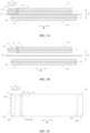
FIG. 1A is a part of a cross-sectional view of an electrode body according to an embodiment of this application,FIG. 1B is an exploded view ofFIG. 1A, and FIG. 1C is a schematic view of a portion of the electrode body of this embodiment as viewed from a positive electrode side; -
FIG. 2A is a part of a cross-sectional view of an electrode body according to another embodiment of this application,FIG. 2B is an exploded view ofFIG. 2A, and FIG. 2C is a schematic view of a portion of the electrode body of this embodiment as viewed from a positive electrode side; -
FIG. 3A is a part of a cross-sectional view of an electrode body according to another embodiment of this application,FIG. 3B is an exploded view ofFIG. 3A, and FIG. 3C is a schematic view of a portion of the electrode body of this embodiment as viewed from a positive electrode side; -
FIG. 4A is a part of a cross-sectional view of an electrode body according to another embodiment of this application,FIG. 4B is an exploded view ofFIG. 4A, and FIG. 4C is a schematic view of a portion of the electrode body of this embodiment as viewed from a positive electrode side; and -
FIG. 5A is a part of a cross-sectional view of an electrode body according to another embodiment of this application,FIG. 5B is an exploded view ofFIG. 5A, and FIG. 5C is a schematic view of a portion of the electrode body of this embodiment as viewed from a positive electrode side. - Reference signs are as follows:
positive electrode 10, positive electrodecurrent collector 11, positive electrodeactive substance layer 12,outer edge 12a of positive electrode active substance layer,insulating layer 13,outer edge 13a of insulating layer,inner edge 13b of insulating layer, overlappingportion 14 of positive electrode active substance layer and insulating layer,negative electrode 20, negative electrodecurrent collector 21, negative electrodeactive substance layer 22,outer edge 22a of negative electrode active substance layer,separator 30, andtab portion 40. - It should be understood that the disclosed embodiments are merely examples of this application. This application may be implemented in various forms. Therefore, specific details disclosed herein should not be interpreted as any limitation, and shall be used merely as a basis for the claims and serve as an illustrative basis to instruct persons skilled in the art to implement this application in various manners.
- In the descriptions of this application, it should be noted that orientations or positional relationships indicated by the terms "length", "width", "thickness", "inside", "outside" and the like is an orientation or positional relationship shown in the accompanying drawings, and are merely for the convenience of describing this application and simplifying the description, rather than indicating or implying that the devices or elements must have a particular orientation, and constructed and operated in the particular orientation. Thus, it cannot be construed as a limitation to this application.
- The electrochemical apparatus of this application is, for example, a primary battery, a secondary battery, a fuel cell, a solar cell, or a capacitor. The secondary battery is, for example, a lithium secondary battery, and the lithium secondary battery includes but is not limited to a lithium metal secondary battery, a lithium-ion secondary battery, a lithium polymer secondary battery, or a lithium-ion polymer secondary battery.
- In some embodiments, the electrochemical apparatus includes a negative electrode, a positive electrode, and a separator.
- Refer to
FIG. 1A to FIG. 5C . Thenegative electrode 20 includes a negative electrodecurrent collector 21, and a negative electrodeactive substance layer 22 is provided on at least one surface of the negative electrodecurrent collector 21. Thepositive electrode 10 includes a positive electrodecurrent collector 11, and a positive electrodeactive substance layer 12 is provided on at least one surface of the positive electrodecurrent collector 11. Theseparator 30 is disposed between thenegative electrode 20 and thepositive electrode 10, and the positive electrodeactive substance layer 12 and the negative electrodeactive substance layer 22 face each other across theseparator 30. Anouter edge 22a of the negative electrode active substance layer extends further outward than anouter edge 12a of the positive electrode active substance layer at an opposite position. - To describe the various orientations clearly,
FIG. 1A to FIG. 5C show a width direction (indicated by W in the figures) and a thickness direction (indicated by T in the figures). The width direction is relative to a length direction. In a case that a wound-type battery with a strip-shaped positive electrode is used as an example, an extension direction of the long side of the rectangular positive electrode current collector is regarded as the length direction, and the width direction is perpendicular to the length direction. As shown inFIG. 1A to FIG. 5C , for the two ends in the width direction, the edge of the positive electrodeactive substance layer 12 close to an edge of the positive electrode current collector is theouter edge 12a of the positive electrode active substance layer, and the edge of the negative electrodeactive substance layer 22 close to an edge of the negative electrode current collector is theouter edge 22a of the negative electrode active substance layer. - To prevent short circuits in the battery and ensure that lithium ions deintercalated from the positive electrode
active substance layer 12 are fully received by the negative electrodeactive substance layer 22, so as to avoid the safety risk of lithium precipitation in a portion of the positive electrodeactive substance layer 12 beyond the negative electrodeactive substance layer 22, a width of the negative electrodeactive substance layer 22 is designed to be greater than a width of the positive electrodeactive substance layer 12, resulting in an overhang region on the negative electrode, as manifested in this application by designing theouter edge 22a of the negative electrode active substance layer to be further outward than theouter edge 12a of the positive electrode active substance layer at an opposite position. In some embodiments, a width B of a portion of theouter edge 22a of the negative electrode active substance layer that extends beyond theouter edge 12a of the positive electrode active substance layer satisfies 0.2 mm ≤ B ≤ 5 mm. In some embodiments, a width B of a portion of theouter edge 22a of the negative electrode active substance layer that extends beyond theouter edge 12a of the positive electrode active substance layer satisfies 0.5 mm ≤ B ≤ 5 mm. In some embodiments, a width B of a portion of theouter edge 22a of the negative electrode active substance layer that extends beyond theouter edge 12a of the positive electrode active substance layer satisfies 0.8 mm ≤ B ≤ 2 mm. - However, the inventor has found that when the width of the negative electrode
active substance layer 22 is greater than that of the positive electrodeactive substance layer 12, impedance near theouter edge 12a of the positive electrode active substance layer corresponding to theouter edge 22a of the negative electrode active substance layer is relatively high, which reduces the kinetics of the edge region of the negative electrode, is prone to lithium precipitation, and poses a safety risk. Lowering the impedance generated during the charging of the negative electrode by reducing the charging rate can avoid lithium precipitation at the edge of the negative electrode, but reducing the charging rate prolongs the charging time, which greatly reduces the customer experience and product competitiveness. Increasing the dynamic behavior of the negative electrode active material. Enhancing the kinetics of a negative electrode active material, increasing the proportion of the negative electrode active material, and enhancing the kinetics of the edge region of the negative electrode by using CMC-Li (carboxymethyl cellulose lithium) instead of CMC-Na (carboxymethyl cellulose sodium) or using binders with better kinetics, such as using styrene-based binders instead of styrene-butadiene rubber binders, has certain effects, but the improvement of kinetics through these methods has developed to a bottleneck period, and it is difficult to improve the kinetics of the negative electrode on the existing basis. - In this application, providing the insulating
layer 13 on the positive electrodecurrent collector 11 and determining a position and size relationship among the insulatinglayer 13, the positive electrodeactive substance layer 12, and the negative electrodeactive substance layer 22 can reduce the impedance in the edge region of the negative electrode, enhance the kinetics of the edge of the negative electrode, alleviate lithium precipitation at the edge of the negative electrode, and reduce the chance of fire or explosion in the electrochemical apparatus. - The insulating
layer 13 may be provided only on a surface of the positive electrodecurrent collector 11 close to thetab portion 40, or may be provided on both a surface of the positive electrodecurrent collector 11 close to thetab portion 40 and a surface of the positive electrodecurrent collector 11 far away from thetab portion 40. - In this application, the
tab portion 40 refers to an empty foil region at the edge of the current collector reserved in coating the electrode plate. In some embodiments, thetab portion 40 protrudes from the current collector. After rolling and slitting, the empty foil region at the edge of the current collector can be cut to form tabs before winding. - In some embodiments, as a portion of the electrode body shown in
FIG. 1A to FIG. 1C , an insulatinglayer 13 is provided on a surface of the positive electrodecurrent collector 11 close to thetab portion 40, aninner edge 13b of the insulating layer is in contact with theouter edge 12a of the positive electrode active substance layer, and anouter edge 13a of the insulating layer extends further outward than theouter edge 22a of the negative electrode active substance layer. In some embodiments, as a portion of the electrode body shown inFIG. 2A to FIG. 2C , an insulatinglayer 13 is provided on a surface of the positive electrodecurrent collector 11 close to thetab portion 40, aninner edge 13b of the insulating layer is in contact with theouter edge 12a of the positive electrode active substance layer, and anouter edge 13a of the insulating layer is flush with theouter edge 22a of the negative electrode active substance layer. - In this case, the insulating
layer 13 has been provided on the surface of the positive electrodecurrent collector 11 close to thetab portion 40, when the electrode plate provided with the insulatinglayer 13 is cut, the burrs and debris generated during cutting can be effectively reduced, improving the safety performance of the electrochemical apparatus. In addition, on the end close to thetab portion 13, the insulatinglayer 13 has been provided on thepositive electrode 10, theinner edge 13b of the insulating layer is in contact with theouter edge 12a of the positive electrode active substance layer, and theouter edge 13a of the insulating layer extends further outward than theouter edge 22a of the negative electrode active substance layer, or theouter edge 13a of the insulating layer is flush with theouter edge 22a of the negative electrode active substance layer. Therefore, during the formation of the battery under pressure, the insulatinglayer 13 on the positive electrode at this end can provide support for the edge region of the negative electrode active substance layer, such that the edge region of the negative electrode active substance layer and the separator can be more tightly bonded, thereby reducing the impedance in the edge region of the negative electrode, and enhancing the kinetics of the edge region of the negative electrode. If theouter edge 13a of the insulating layer extends further inward than theouter edge 22a of the negative electrode active substance layer, the portion of the negative electrodeactive substance layer 22 that extends beyond the insulating layer is in a suspended state. During the formation of the battery under pressure, the bond between this extended portion and the separator is not tight enough, resulting in a large electron transmission distance and high impedance, and making lithium more easily precipitated. - During the application of slurry, when an insulating
layer 13 slurry and a positive electrodeactive substance layer 12 slurry are applied on a surface of the positive electrodecurrent collector 11, the insulating layer slurry is applied along the edge of the positive electrode active substance layer slurry, and the insulating layer slurry and the positive electrode active substance layer slurry may partially overlap to form an overlappingregion 14 of the positive electrodeactive substance layer 12 and the insulatinglayer 13. In some embodiments, as a portion of the electrode body shown inFIG. 3A to FIG. 3C , an insulatinglayer 13 is provided on a surface of the positive electrodecurrent collector 11 close to thetab portion 40, aninner edge 13b of the insulating layer partially overlaps with theouter edge 12a of the positive electrode active substance layer, and anouter edge 13a of the insulating layer extends further outward than theouter edge 22a of the negative electrode active substance layer. In some embodiments, as a portion of the electrode body shown inFIG. 4A to FIG. 4C , an insulatinglayer 13 is provided on a surface of the positive electrodecurrent collector 11 close to thetab portion 40, aninner edge 13b of the insulating layer partially overlaps with theouter edge 12a of the positive electrode active substance layer, and anouter edge 13a of the insulating layer is flush with theouter edge 22a of the negative electrode active substance layer. - In some embodiments, as a portion of the electrode body shown in
FIG. 5A to FIG. 5C , an insulatinglayer 13 is provided on both a surface of the positive electrodecurrent collector 11 close to thetab portion 40 and a surface of the positive electrodecurrent collector 11 far away from thetab portion 40, aninner edge 13b of the insulating layer is in contact with theouter edge 12a of the positive electrode active substance layer, and anouter edge 13a of the insulating layer extends further outward than theouter edge 22a of the negative electrode active substance layer. - When the insulating
layer 13 is provided on both the surface of the positive electrodecurrent collector 11 close to thetab portion 40 and the surface of the positive electrodecurrent collector 11 far away from thetab portion 40, theinner edge 13b of the insulating layer may alternatively partially overlap with theouter edge 12a of the positive electrode active substance layer, and theouter edge 13a of the insulating layer may alternatively be flush with theouter edge 22a of the negative electrode active substance layer. Specifically, it is similar to the solution that the insulatinglayer 12 is disposed on only the surface of thepositive electrode collector 11 close to thetab portion 40, and details are not repeated herein. - In this case, the insulating
layer 13 is also provided on the surface of the positive electrodecurrent collector 11 far away from thetab portion 40, so a total width of the positive electrodeactive substance layer 12 and the insulatinglayer 13 becomes larger than the width of the negative electrodeactive substance layer 22. Therefore, during the formation of the battery under pressure, the overhang region of the negative electrode can be supported by the insulating layer, allowing for a further tight bind between the edge region of the negative electrode active substance layer and the separator. - In some embodiments, the insulating layer includes an inorganic material. In this application, the inorganic material can be a conventional inorganic material commonly used in the art. In some embodiments, the inorganic material includes at least one of barium sulfate (BaSO4), calcium silicate (CaSiO3), aluminum oxide (Al2O3), boehmite, magnesium hydroxide, aluminum hydroxide, silicon dioxide, magnesium oxide, or calcium orthosilicate (CaSiO4). In some embodiments, based on a total weight of the insulating layer, a weight percentage of the inorganic material ranges from 60% to 93%. In some embodiments, based on the total weight of the insulating layer, a weight percentage of the inorganic material ranges from 80% to 93%.
- In some embodiments, the insulating layer further includes a binder. The binder includes at least one of polyvinylidene fluoride, polyurethane, polyacrylate, styrene-butadiene rubber, polyetherimide, carboxymethyl cellulose sodium, or acrylate. In some embodiments, based on a total weight of the insulating layer, a weight percentage of the binder ranges from 7% to 40%.
- In some embodiments, impedance of the insulating layer is greater than or equal to 1 kQ, which can prevent the burrs generated during cutting the positive electrode current collector and the insulating layer from having electron transmission occurred, thereby separating the burrs on the positive electrode current collector from the separator. The impedance of the insulating layer can be tested using an internal resistance meter as follows: cleaning the contact heads of the internal resistance meter with lint-free paper dipped in alcohol; turning on the power of the test fixture and adjusting the pressure of the contact head to 0.5 MPa; placing the electrode plate under test on the lower contact head, starting the equipment, and pressing the upper contact head onto the electrode for 3 to 5 seconds; and recording the resistance value of the electrode plate, which represents the impedance of the insulating layer.
- In some embodiments, as shown in
FIG. 1A to FIG. 5C , a width A of a portion of theouter edge 13a of the insulating layer that extends beyond theouter edge 22a of the negative electrode active substance layer satisfies A ≤ 3 mm. If the width A of the portion of theouter edge 13a of the insulating layer that extends beyond the outer edge of the negative electrode active substance layer is too large, the width of the separator requires to be correspondingly increased, resulting in a loss of energy density of the electrochemical apparatus. Furthermore, even if A is greater than 3 mm, there is no significant further improvement effect or only a weak improvement effect on lithium precipitation at the edge of the negative electrode. In some embodiments, the width A of a portion of theouter edge 13a of the insulating layer that extends beyond theouter edge 22a of the negative electrode active substance layer satisfies 1.5 mm ≤ A ≤ 3 mm. - In some embodiments, as shown in
FIG. 1A to FIG. 5C , a width A' of the insulatinglayer 13 satisfies 0.2 mm ≤ A' ≤ 10 mm. In this application, the width of the insulating layer is a width of the insulating layer on the side of the positive electrode active substance layer, to be specific, a width of the portion of which the outer edge of the insulating layer extends beyond the outer edge of the positive electrode active substance layer. If the width A' of the insulating layer is too large, the width of the separator requires to be correspondingly increased, resulting in a loss of energy density of the electrochemical apparatus. Furthermore, even if A' is greater than 10 mm, there is no significant further improvement effect or only a weak improvement effect on lithium precipitation at the edge of the negative electrode. If the width A' of the insulating layer is too small, it would not effectively reduce the burrs and debris generated during cutting, affecting the improvement in safety performance. In some embodiments, the width A' of the insulatinglayer 13 satisfies 1 mm ≤ A' ≤ 5 mm. In some embodiments, the width A' of the insulatinglayer 13 satisfies 3 mm ≤ A' ≤ 5 mm. - In some embodiments of this application, the total width of the positive electrode
active substance layer 12 and the insulatinglayer 13 does not exceed the width of theseparator 30, to minimize the impact on the battery width and avoid a loss in energy density of the electrochemical apparatus. - The thickness of the insulating layer affects its support effect on the edge region of the negative electrode active substance layer. In some embodiments, a thickness Ti of the insulating layer and a thickness Tp of the positive electrode active substance layer satisfy 0 µm ≤ Tp - Ti ≤ 10 µm. If the thickness of the insulating layer relative to the thickness of the positive electrode active substance layer is too small, the support effect of the insulating layer on the edge region of the negative electrode active substance layer is weakened, affecting the improvement effect on lithium precipitation at the edge of the negative electrode. If the thickness of the insulating layer is greater than the thickness of the positive electrode active substance layer, it would be difficult to achieve the desired compacted density during cold pressing, which in turn affects the energy density of the electrochemical apparatus. In some embodiments, a thickness Ti of the insulating layer and a thickness Tp of the positive electrode active substance layer satisfy 0 µm ≤ Tp - Ti ≤ 2 µm.
- In some embodiments, a thickness Ti of the insulating layer satisfies 10 µm ≤ Ti ≤ Tp.
- It should be noted that in this application, the thickness Ti of the insulating layer is a thickness of the insulating layer on a single surface of the positive electrode current collector, and the thickness Tp of the positive electrode active substance layer is a thickness of the positive electrode active substance layer on a single surface of the positive electrode current collector.
- In some embodiments, the negative electrode current collector includes a metal, for example, but is not limited to copper foil, nickel foil, stainless steel foil, titanium foil, nickel foam, copper foam, a polymer base coated with conductive metal, or a combination thereof.
- The negative electrode active substance layer includes a negative electrode active material. The negative electrode active material can be selected from any material capable of intercalating and deintercalating active ions or doping and dedoping active ions that is suitable for use in an electrochemical apparatus. In some embodiments, the negative electrode active material includes at least one of a carbon material, a metal alloy, a lithium-containing oxide, or a silicon-containing material. The preparation method of the negative electrode can be any method suitable for preparing a negative electrode for an electrochemical apparatus. In some embodiments, in the preparation of negative electrode slurry, a solvent is typically added. The negative electrode active material is added with a negative electrode binder, and as needed, a conductive material and a thickener are added and then dissolved or dispersed in the solvent to form the negative electrode slurry. The solvent is evaporated and removed during the drying. The solvent is a solvent that can be used for the negative electrode active substance layer, for example, but not limited to, an aqueous solution. The thickener is a thickener that can be used for the negative electrode active substance layer, for example, but not limited to, carboxymethyl cellulose sodium (CMC for short). This application does not particularly impose any limitation on the mixing ratio of the negative electrode active material, negative electrode binder, and thickener in the negative electrode active substance layer, and the mixing ratio can be controlled based on the desired performance of the electrochemical apparatus.
- In some embodiments, the positive electrode current collector includes a metal, for example, but not limited to, copper foil, and aluminum foil.
- The positive electrode active substance layer includes a positive electrode active material. The positive electrode active material can be selected from any material capable of reversibly intercalating and deintercalating active ions that is suitable for use in an electrochemical apparatus. In some embodiments, the positive electrode active material includes at least one of LiCoO2, LiNiO2, LiMn2O4, LiCo1-yMyO2, LiNi1-yMyO2, LiMn2-yMyO4, or LiNixCoyMnzM1-x-y-zO2, where M is selected from one or more of Fe, Co, Ni, Mn, Mg, Cu, Zn, Al, Sn, B, Ga, Cr, Sr, V, and Ti, and 0 ≤ y < 1, 0 ≤ x ≤ 1, 0 ≤ z ≤ 1, x + y + z ≤ 1. The preparation method of the positive electrode can be any method suitable for preparing a positive electrode for an electrochemical apparatus. In some embodiments, in the preparation of positive electrode slurry, a solvent is typically added. The positive electrode active material is added with a positive electrode binder, and as needed, a conductive agent and a thickener are added and then dissolved or dispersed in the solvent to form the positive electrode slurry. The solvent is evaporated and removed during the drying. The solvent is a solvent that can be used for the positive electrode active material layer, for example, but not limited to, N-methyl-2-pyrrolidone (NMP). The binder is a binder that can be used for the positive electrode active material layer, for example, but not limited to, polyvinylidene fluoride (PVDF). The conductive agent is a conductive agent that can be used for the positive electrode active material layer, for example, but not limited to, Super P. This application does not particularly impose any limitation on the mixing ratio of the positive electrode active material, positive electrode binder, and positive electrode conductive agent in the positive electrode active substance, and the mixing ratio can be controlled based on the desired performance of the electrochemical apparatus.
- The separator is a separator that can be used in an electrochemical apparatus. This application does not particularly impose any limitation on the material and shape of the separator.
- The electrochemical apparatus further includes an electrolyte. The electrolyte is an electrolyte that can be used for an electrochemical apparatus in the art. In some embodiments, the electrolyte includes an organic solvent, an electrolytic salt, and an additive. In some embodiments, the electrolytic salt is selected from a lithium salt. In some embodiments, the lithium salt is selected from LiPF6.
- In some embodiments, the electrochemical apparatus further includes an outer packaging shell. The outer packaging shell is an outer packaging shell that can be used for an electrochemical apparatus in the art and be stable to the electrolyte used, for example, but not limited to, a metallic outer packaging shell.
- In some embodiments, the tab portion includes multiple positive electrode tabs and multiple negative electrode tabs. The multiple tabs can increase the electronic pathways during charge and discharge of the electrochemical apparatus, reduce polarization, and dissipate heat from the cell. In some embodiments, the number of positive electrode tabs and the number of negative electrode tabs are each equal to the number of cell layers, or the number of positive electrode tabs and the number of negative electrode tabs are each equal to 1/2 of the number of cell layers. The positive electrode tabs and the negative electrode tabs overlap after the cell is wound and are separately welded to nickel-aluminum metal sheets.
- The electronic apparatus of this application may be any electronic apparatus, for example, but is not limited to, notebook computers, pen-input computers, mobile computers, electronic book players, portable telephones, portable fax machines, portable copiers, portable printers, stereo headsets, video recorders, liquid crystal display televisions, portable cleaners, portable CD players, mini-disc players, transceivers, electronic notebooks, calculators, storage cards, portable recorders, radios, backup power sources, motors, automobiles, motorcycles, motor bicycles, bicycles, lighting appliances, toys, game machines, clocks, electric tools, flash lamps, cameras, large household batteries, and lithium-ion capacitors. It should be noted that the electrochemical apparatus of this application is not only applicable to the electronic apparatus listed above but also applicable to energy storage power stations, marine vehicles, and air vehicles. The air vehicles include airborne vehicles inside the atmosphere and airborne vehicles outside the atmosphere.
- In some embodiments, the electronic apparatus includes the electrochemical apparatus described above in this application.
- This application is further described with reference to Examples. It should be understood that these examples are merely used to describe this application but not to limit the scope of this application. In the following specific examples of this application, only an example in which the battery is a lithium-ion battery is shown, but this application is not limited thereto. In the following examples and comparative examples, all reagents, materials, and instruments used are commercially available or synthesized unless otherwise specified.
- Step S1: Positive electrode active material lithium cobalt oxide, conductive agent Super P, and binder PVDF were mixed at a weight ratio of 98:1:1 in a proper amount of NMP to obtain a well-mixed positive electrode slurry. Inorganic material BaSO4 and the binder PVDF were mixed at a weight ratio of 93:7 in a proper amount of NMP to obtain a well-mixed insulating slurry.
- Step S2: The prepared positive electrode slurry was applied on one side of a positive electrode current collector aluminum foil using a coating machine, with a coating thickness of 30 µm. The insulating slurry was applied along the edge of the positive electrode slurry on a side of the positive electrode slurry close to the tab portion, with a coating width of 3.5 mm and a coating thickness of 30 µm. After drying, the same process was repeated to apply the positive electrode slurry on the other side of the positive electrode current collector aluminum foil, followed by drying and cold pressing to obtain a positive electrode.
- Step S3: Negative electrode active material graphite, binder styrene-butadiene rubber, thickener carboxymethyl cellulose lithium were fully stirred and mixed at a weight ratio of 97.5:1.3:1.2 in a proper amount of deionized water to obtain a well-mixed negative electrode slurry. The negative electrode slurry was applied on one side of a negative electrode current collector copper foil using a coating machine. After drying, the same process was repeated to apply the negative electrode slurry on the other side of the negative electrode current collector copper foil, followed by drying and cold pressing to obtain a negative electrode.
- Step S4: A porous polyethylene PE film is used as the separator. The separator was placed between the negative electrode and the positive electrode, and the positive electrode active substance layer and negative electrode active substance layer face each other across the separator. The outer edge of the negative electrode active substance layer extended 2 mm beyond the outer edge of the positive electrode active substance layer, and the outer edge of the insulating layer extended 1.5 mm beyond the outer edge of the negative electrode active substance layer.
- Step S5: The stacked separator, negative electrode, and positive electrode were wound to form an electrode assembly. The electrode assembly was then encapsulated, and the electrolyte was injected in the encapsulation for sufficient impregnation. After that, the electrode assembly undergone formation and aging steps to obtain a lithium-ion battery.
- The preparation methods in Examples 2 to 21 were the same as that in Example 1, except that the parameters of the insulating layer, positive electrode active substance layer, and negative electrode active substance layer were adjusted.
- The preparation method in Example 22 was the same as that in Example 1, except that the insulating slurry was coated on both sides of the positive electrode slurry (one side close to the tab portion and the other side far away from the tab portion), with the coating width of the insulating slurry on each side of 8 mm, and that the parameters of the insulating layer, positive electrode active substance layer, and negative electrode active substance layer were adjusted in Example 22.
- The preparation method in Example 23 was the same as that in Example 22, except that the parameters of the insulating layer, positive electrode active substance layer, and negative electrode active substance layer were adjusted.
- The preparation method in Example 24 was the same as that in Example 5, except that the parameters of the insulating layer, positive electrode active substance layer, and negative electrode active substance layer were adjusted.
- The preparation methods in Comparative Examples 1 and 2 were the same as that in Example 1, except that the parameters of the insulating layer, positive electrode active substance layer, and negative electrode active substance layer were adjusted. In Comparative Examples 1 and 2, the outer edge of the negative electrode active substance layer was further outward than the outer edge of the insulating layer.
- Related parameters of Examples 1 to 24 and Comparative Examples 1 and 2 are shown in Table 1.
-
- (1) At 20±5°C, discharged the battery at 0.5C to 3.0 V, and left it standing for 5 min;
- (2) Charged the battery at 0.5C to 4.45 V, and charged at constant voltage to 0.05C (4.45 V system);
- (3) Left standing at 20±5°C for 60 min;
- (4) Heated at a rate of 5°C/min ±2°C/min to 130°C±2°C and maintained this temperature for 60 min;
- (5) After the test, checked the appearance of the cell. If the battery caught fire, the test failed.
- The test was carried out at 25°C.
- (1) Left the battery standing for 30 min;
- (2) Charged at 0.5C to 4.45 V, and charged at the constant current to 0.05C;
- (3) Left standing for 5 min;
- (4) Discharged at 0.5C to 3 V;
- (5) Left standing for 60 min;
- (6) Charged at 3C to 4.45 V, and charged at the constant current to 0.05C;
- (7) Left standing for 5 min;
- (8) Discharged at 1C to 3 V;
- (9) Left standing for 5 min;
- (10) Repeated 10 times from step 6 to step 9;
- (11) Left standing for 120 min;
- (12) Charged at 3C to 4.45 V, and charged at the constant current to 0.05C;
- (13) Left standing for 5 min; observed whether the lithium-ion battery had lithium precipitation occurred, and classified according to the following standards.
- The lithium-ion battery was disassembled to obtain the negative plate. The golden yellow represented the normal region, and the white represented the lithium precipitation region. After pictures were taken with a high-power (more than 20 times) microscope, the different regions were analyzed. If a proportion n of the white region in the total area satisfied 0 < n < 1%, the white region was recorded as "no lithium precipitation"; if the proportion n of the white region in the total area satisfied 1% < n < 10%, the white region was recorded as "slight lithium precipitation"; and if a proportion n of the white region in the total area satisfied 10% < n < 100%, the white region was recorded as "serious lithium precipitation".


- It can be concluded from the analysis of the data in Table 1 that when the outer edge of the negative electrode active substance layer extends further outward than the outer edge of the positive electrode active substance layer at an opposite position, the insulating layer is disposed on a side of the positive electrode current collector close to the tab portion, the inner edge of the insulating layer is made to be in contact with or partially overlap with the outer edge of the positive electrode active substance layer, and the outer edge of the insulating layer is made to be flush with or further outward than the outer edge of the negative electrode active substance layer. In this way, lithium precipitation at the negative electrode of the lithium-ion battery can be alleviated and the pass rate of the hotbox test can be increased. In Comparative Examples 1 and 2, although the insulating layer is disposed on the side of the positive electrode current collector close to the tab portion, after the cell is manufactured, the outer edge of the negative electrode active substance layer extends further outward than the outer edge of the insulating layer. Therefore, the insulating layer cannot provide support to the edge region of the negative electrode active substance layer, lithium precipitation is prone to occur at the negative electrode, and the pass rate of the hotbox test is relatively low.
- The thickness of the insulating layer affects the alleviation of lithium precipitation at the negative electrode and the improvement effect of the pass rate of the hotbox test for the lithium-ion battery. It can be concluded from the data of Examples 8 to 12 that if the thickness of the insulating layer is too small, the effect of alleviating lithium precipitation at the negative electrode and increasing the pass rate of the hotbox test for the lithium-ion battery becomes poor.
- The composition and impedance of the insulating layer affects the improvement effect of the pass rate of the hotbox test for the lithium-ion battery. It can be concluded from the data of Examples 9, and 14 to 21 that if the mass proportion of the inorganic material in the insulating layer is too small, the impedance of the insulating layer is relatively low, the effect of increasing the pass rate of the hotbox test for the lithium-ion battery becomes poor.
- The foregoing detailed descriptions describe a plurality of example embodiments. However, this specification is not intended to limit the explicitly disclosed combinations. Therefore, unless otherwise stated, various features disclosed herein may be combined together to form a plurality of other combinations that are not shown for simplicity purposes.
Claims (11)
- An electrochemical apparatus, comprising:a negative electrode, wherein the negative electrode comprises a negative electrode current collector, and a negative electrode active substance layer is provided on at least one surface of the negative electrode current collector;a positive electrode, wherein the positive electrode comprises a positive electrode current collector, a positive electrode active substance layer disposed on at least one surface of the positive electrode current collector, and an insulating layer disposed on a surface of the positive electrode current collector close to a tab portion; anda separator, wherein the separator is disposed between the negative electrode and the positive electrode, and the positive electrode active substance layer and the negative electrode active substance layer face each other across the separator;wherein,an outer edge of the negative electrode active substance layer extends further outward than an outer edge of the positive electrode active substance layer at an opposite position; andan inner edge of the insulating layer is in contact with or partially overlaps with the outer edge of the positive electrode active substance layer; and an outer edge of the insulating layer is flush with the outer edge of the negative electrode active substance layer or extends further outward than the outer edge of the negative electrode active substance layer.
- The electrochemical apparatus according to claim 1, wherein
the insulating layer is provided on a surface of the positive electrode current collector far away from the tab portion. - The electrochemical apparatus according to claim 1 or 2, wherein
a width A of a portion of the outer edge of the insulating layer that extends beyond the outer edge of the negative electrode active substance layer satisfies A ≤ 3 mm. - The electrochemical apparatus according to claim 1 or 2, wherein
a width A' of the insulating layer satisfies 0.2 mm ≤ A' ≤ 10 mm. - The electrochemical apparatus according to claim 1 or 2, wherein
a width B of a portion of the outer edge of the negative electrode active substance layer that extends beyond the outer edge of the positive electrode active substance layer satisfies 0.2 mm ≤ B ≤ 5 mm. - The electrochemical apparatus according to claim 1 or 2, wherein
a thickness Ti of the insulating layer and a thickness Tp of the positive electrode active substance layer satisfy 0 µm ≤ Tp - Ti ≤ 10 µm. - The electrochemical apparatus according to claim 1 or 2, wherein
a thickness Ti of the insulating layer satisfies 10 µm ≤ Ti ≤ Tp. - The electrochemical apparatus according to claim 1 or 2, wherein the insulating layer comprises an inorganic material and a binder; wherein
the inorganic material comprises at least one of barium sulfate, calcium silicate, aluminum oxide, boehmite, magnesium hydroxide, aluminum hydroxide, silicon dioxide, magnesium oxide, or calcium orthosilicate; and the binder comprises at least one of polyvinylidene fluoride, polyurethane, polyacrylate, styrene-butadiene rubber, polyetherimide, carboxymethyl cellulose sodium, or acrylate. - The electrochemical apparatus according to claim 8, wherein
based on a total weight of the insulating layer, a weight percentage of the inorganic material ranges from 60% to 93%, and a weight percentage of the binder ranges from 7% to 40%. - The electrochemical apparatus according to claim 1 or 2, wherein
an impedance of the insulating layer is greater than or equal to 1 KΩ. - An electronic apparatus, comprising the electrochemical apparatus according to any one of claims 1 to 10.
Applications Claiming Priority (1)
| Application Number | Priority Date | Filing Date | Title |
|---|---|---|---|
| PCT/CN2021/076725 WO2022174369A1 (en) | 2021-02-18 | 2021-02-18 | Electrochemical device and electronic device |
Publications (1)
| Publication Number | Publication Date |
|---|---|
| EP4297119A1 true EP4297119A1 (en) | 2023-12-27 |
Family
ID=78918822
Family Applications (1)
| Application Number | Title | Priority Date | Filing Date |
|---|---|---|---|
| EP21926091.6A Pending EP4297119A1 (en) | 2021-02-18 | 2021-02-18 | Electrochemical device and electronic device |
Country Status (5)
| Country | Link |
|---|---|
| US (1) | US20240213635A1 (en) |
| EP (1) | EP4297119A1 (en) |
| JP (1) | JP2024508700A (en) |
| CN (1) | CN113826262A (en) |
| WO (1) | WO2022174369A1 (en) |
Families Citing this family (5)
| Publication number | Priority date | Publication date | Assignee | Title |
|---|---|---|---|---|
| CN114430018B (en) * | 2022-01-19 | 2024-07-19 | 宁德新能源科技有限公司 | Electrochemical device and electronic device comprising same |
| CN114744156B (en) * | 2022-03-30 | 2024-06-28 | 惠州市恒泰科技股份有限公司 | Positive electrode plate structure and preparation method thereof |
| CN114744198B (en) * | 2022-04-19 | 2024-04-02 | 珠海冠宇电池股份有限公司 | Battery cell and battery |
| CN114843519A (en) * | 2022-05-26 | 2022-08-02 | 东莞锂威能源科技有限公司 | Current collector, positive plate, negative plate, laminated battery cell, battery and preparation method |
| CN115832449B (en) * | 2023-02-10 | 2023-05-19 | 宁德新能源科技有限公司 | Electrochemical device and electronic device |
Family Cites Families (6)
| Publication number | Priority date | Publication date | Assignee | Title |
|---|---|---|---|---|
| JP2007103356A (en) * | 2005-09-12 | 2007-04-19 | Matsushita Electric Ind Co Ltd | Non-aqueous secondary battery |
| US9231245B2 (en) * | 2011-03-23 | 2016-01-05 | Sanyo Electric Co., Ltd. | Positive electrode plate for nonaqueous electrolyte secondary battery, method for manufacturing the positive electrode plate, nonaqueous electrolyte secondary battery, and method for manufacturing the battery |
| JP6252841B2 (en) * | 2013-11-25 | 2017-12-27 | 株式会社Gsユアサ | Electricity storage element |
| JP7221592B2 (en) * | 2017-11-08 | 2023-02-14 | 三星エスディアイ株式会社 | Composition for forming porous insulating layer, electrode for non-aqueous electrolyte secondary battery, non-aqueous electrolyte secondary battery, and method for producing electrode for non-aqueous electrolyte secondary battery |
| JP7085148B2 (en) * | 2019-04-09 | 2022-06-16 | トヨタ自動車株式会社 | Lithium ion battery |
| CN112133925B (en) * | 2019-04-26 | 2021-10-26 | 宁德时代新能源科技股份有限公司 | Battery, electric automobile and consumer electronics |
-
2021
- 2021-02-18 CN CN202180003251.3A patent/CN113826262A/en active Pending
- 2021-02-18 JP JP2023548322A patent/JP2024508700A/en active Pending
- 2021-02-18 WO PCT/CN2021/076725 patent/WO2022174369A1/en active Application Filing
- 2021-02-18 US US18/277,902 patent/US20240213635A1/en active Pending
- 2021-02-18 EP EP21926091.6A patent/EP4297119A1/en active Pending
Also Published As
| Publication number | Publication date |
|---|---|
| JP2024508700A (en) | 2024-02-28 |
| CN113826262A (en) | 2021-12-21 |
| US20240213635A1 (en) | 2024-06-27 |
| WO2022174369A1 (en) | 2022-08-25 |
Similar Documents
| Publication | Publication Date | Title |
|---|---|---|
| EP4297119A1 (en) | Electrochemical device and electronic device | |
| WO2021023137A1 (en) | Lithium-ion battery and device | |
| CN113097441B (en) | Electrochemical device and electronic device | |
| CN113659105B (en) | Electrochemical device and electronic device | |
| CN114156607A (en) | Electrochemical device and electronic device | |
| WO2023164794A1 (en) | Electrochemical device, and electronic device comprising same | |
| US20240266606A1 (en) | Lithium-ion battery, battery module, battery pack, and electric device | |
| CN114843440A (en) | Electrochemical device, method for manufacturing the same, and electronic device | |
| JP2011192561A (en) | Manufacturing method for nonaqueous electrolyte secondary battery | |
| CN114843441A (en) | Electrochemical device, method for manufacturing the same, and electronic device | |
| CN114041226A (en) | Electrochemical device and electronic device comprising same | |
| CN102709602B (en) | Manufacturing method of high energy-density lithium-ion secondary battery | |
| EP4044313A1 (en) | Electrolyte and electrochemical device and electronic device comprising same | |
| CN116072817B (en) | Electrochemical device and electricity using device | |
| US20230246272A1 (en) | Electrochemical apparatus and electronic apparatus | |
| WO2024036507A1 (en) | Electrochemical device and electronic device | |
| WO2014068930A1 (en) | Nonaqueous electrolyte secondary battery | |
| JP5086644B2 (en) | Nonaqueous electrolyte secondary battery | |
| KR20230054657A (en) | lithium ion battery | |
| JP3624793B2 (en) | Lithium ion battery | |
| US20240170652A1 (en) | Positive electrode active material, preparation method thereof, and lithium-ion battery, battery module, battery pack, and electric apparatus containing same | |
| WO2024169402A1 (en) | Negative electrode additive, negative electrode sheet, secondary battery, and electric device | |
| WO2024098171A1 (en) | Battery cell and preparation method therefor, secondary battery, and electrical apparatus | |
| WO2023092274A1 (en) | Electrochemical device and electronic device comprising electrochemical device | |
| JPH0896839A (en) | Lithium ion secondary battery |
Legal Events
| Date | Code | Title | Description |
|---|---|---|---|
| STAA | Information on the status of an ep patent application or granted ep patent |
Free format text: STATUS: THE INTERNATIONAL PUBLICATION HAS BEEN MADE |
|
| PUAI | Public reference made under article 153(3) epc to a published international application that has entered the european phase |
Free format text: ORIGINAL CODE: 0009012 |
|
| STAA | Information on the status of an ep patent application or granted ep patent |
Free format text: STATUS: REQUEST FOR EXAMINATION WAS MADE |
|
| 17P | Request for examination filed |
Effective date: 20230915 |
|
| AK | Designated contracting states |
Kind code of ref document: A1 Designated state(s): AL AT BE BG CH CY CZ DE DK EE ES FI FR GB GR HR HU IE IS IT LI LT LU LV MC MK MT NL NO PL PT RO RS SE SI SK SM TR |
|
| DAV | Request for validation of the european patent (deleted) | ||
| DAX | Request for extension of the european patent (deleted) |