EP4297047A1 - Duplex twisted shielded cable, and wire harness - Google Patents
Duplex twisted shielded cable, and wire harness Download PDFInfo
- Publication number
- EP4297047A1 EP4297047A1 EP23173325.4A EP23173325A EP4297047A1 EP 4297047 A1 EP4297047 A1 EP 4297047A1 EP 23173325 A EP23173325 A EP 23173325A EP 4297047 A1 EP4297047 A1 EP 4297047A1
- Authority
- EP
- European Patent Office
- Prior art keywords
- metal foil
- foil shield
- shielded cable
- duplex
- metal
- Prior art date
- Legal status (The legal status is an assumption and is not a legal conclusion. Google has not performed a legal analysis and makes no representation as to the accuracy of the status listed.)
- Pending
Links
- 229910052751 metal Inorganic materials 0.000 claims abstract description 130
- 239000002184 metal Substances 0.000 claims abstract description 130
- 239000011888 foil Substances 0.000 claims abstract description 81
- 239000004020 conductor Substances 0.000 claims abstract description 23
- 229920002799 BoPET Polymers 0.000 claims abstract description 13
- 239000012212 insulator Substances 0.000 claims abstract description 13
- 239000010410 layer Substances 0.000 description 44
- 230000005540 biological transmission Effects 0.000 description 18
- 230000000052 comparative effect Effects 0.000 description 17
- 238000005452 bending Methods 0.000 description 11
- RYGMFSIKBFXOCR-UHFFFAOYSA-N Copper Chemical compound [Cu] RYGMFSIKBFXOCR-UHFFFAOYSA-N 0.000 description 9
- 230000006866 deterioration Effects 0.000 description 9
- 239000011347 resin Substances 0.000 description 5
- 229920005989 resin Polymers 0.000 description 5
- 238000000034 method Methods 0.000 description 4
- 239000004698 Polyethylene Substances 0.000 description 3
- 239000004743 Polypropylene Substances 0.000 description 3
- 229910052802 copper Inorganic materials 0.000 description 3
- 239000010949 copper Substances 0.000 description 3
- 238000003780 insertion Methods 0.000 description 3
- 230000037431 insertion Effects 0.000 description 3
- -1 polyethylene Polymers 0.000 description 3
- 229920000573 polyethylene Polymers 0.000 description 3
- 229920000139 polyethylene terephthalate Polymers 0.000 description 3
- 239000005020 polyethylene terephthalate Substances 0.000 description 3
- 229920001155 polypropylene Polymers 0.000 description 3
- 239000007787 solid Substances 0.000 description 3
- 239000011800 void material Substances 0.000 description 3
- 229910000881 Cu alloy Inorganic materials 0.000 description 2
- NMFHJNAPXOMSRX-PUPDPRJKSA-N [(1r)-3-(3,4-dimethoxyphenyl)-1-[3-(2-morpholin-4-ylethoxy)phenyl]propyl] (2s)-1-[(2s)-2-(3,4,5-trimethoxyphenyl)butanoyl]piperidine-2-carboxylate Chemical compound C([C@@H](OC(=O)[C@@H]1CCCCN1C(=O)[C@@H](CC)C=1C=C(OC)C(OC)=C(OC)C=1)C=1C=C(OCCN2CCOCC2)C=CC=1)CC1=CC=C(OC)C(OC)=C1 NMFHJNAPXOMSRX-PUPDPRJKSA-N 0.000 description 2
- 239000012790 adhesive layer Substances 0.000 description 2
- 229910052782 aluminium Inorganic materials 0.000 description 2
- XAGFODPZIPBFFR-UHFFFAOYSA-N aluminium Chemical compound [Al] XAGFODPZIPBFFR-UHFFFAOYSA-N 0.000 description 2
- 239000000835 fiber Substances 0.000 description 2
- 238000012986 modification Methods 0.000 description 2
- 230000004048 modification Effects 0.000 description 2
- 238000007747 plating Methods 0.000 description 2
- 229920000098 polyolefin Polymers 0.000 description 2
- 238000012360 testing method Methods 0.000 description 2
- 238000009966 trimming Methods 0.000 description 2
- 238000009941 weaving Methods 0.000 description 2
- 238000004804 winding Methods 0.000 description 2
- RNFJDJUURJAICM-UHFFFAOYSA-N 2,2,4,4,6,6-hexaphenoxy-1,3,5-triaza-2$l^{5},4$l^{5},6$l^{5}-triphosphacyclohexa-1,3,5-triene Chemical compound N=1P(OC=2C=CC=CC=2)(OC=2C=CC=CC=2)=NP(OC=2C=CC=CC=2)(OC=2C=CC=CC=2)=NP=1(OC=1C=CC=CC=1)OC1=CC=CC=C1 RNFJDJUURJAICM-UHFFFAOYSA-N 0.000 description 1
- 230000002500 effect on skin Effects 0.000 description 1
- 238000001125 extrusion Methods 0.000 description 1
- 239000003063 flame retardant Substances 0.000 description 1
- 239000006247 magnetic powder Substances 0.000 description 1
- 150000002739 metals Chemical class 0.000 description 1
- 230000002093 peripheral effect Effects 0.000 description 1
- 239000004800 polyvinyl chloride Substances 0.000 description 1
- 230000002265 prevention Effects 0.000 description 1
- 238000012545 processing Methods 0.000 description 1
- 230000008054 signal transmission Effects 0.000 description 1
- 230000000087 stabilizing effect Effects 0.000 description 1
Images


Classifications
-
- H—ELECTRICITY
- H01—ELECTRIC ELEMENTS
- H01B—CABLES; CONDUCTORS; INSULATORS; SELECTION OF MATERIALS FOR THEIR CONDUCTIVE, INSULATING OR DIELECTRIC PROPERTIES
- H01B7/00—Insulated conductors or cables characterised by their form
- H01B7/17—Protection against damage caused by external factors, e.g. sheaths or armouring
-
- H—ELECTRICITY
- H01—ELECTRIC ELEMENTS
- H01B—CABLES; CONDUCTORS; INSULATORS; SELECTION OF MATERIALS FOR THEIR CONDUCTIVE, INSULATING OR DIELECTRIC PROPERTIES
- H01B11/00—Communication cables or conductors
- H01B11/02—Cables with twisted pairs or quads
- H01B11/06—Cables with twisted pairs or quads with means for reducing effects of electromagnetic or electrostatic disturbances, e.g. screens
- H01B11/10—Screens specially adapted for reducing interference from external sources
- H01B11/1016—Screens specially adapted for reducing interference from external sources composed of a longitudinal lapped tape-conductor
-
- H—ELECTRICITY
- H01—ELECTRIC ELEMENTS
- H01B—CABLES; CONDUCTORS; INSULATORS; SELECTION OF MATERIALS FOR THEIR CONDUCTIVE, INSULATING OR DIELECTRIC PROPERTIES
- H01B11/00—Communication cables or conductors
- H01B11/02—Cables with twisted pairs or quads
- H01B11/06—Cables with twisted pairs or quads with means for reducing effects of electromagnetic or electrostatic disturbances, e.g. screens
- H01B11/10—Screens specially adapted for reducing interference from external sources
- H01B11/1008—Features relating to screening tape per se
-
- H—ELECTRICITY
- H01—ELECTRIC ELEMENTS
- H01B—CABLES; CONDUCTORS; INSULATORS; SELECTION OF MATERIALS FOR THEIR CONDUCTIVE, INSULATING OR DIELECTRIC PROPERTIES
- H01B11/00—Communication cables or conductors
- H01B11/02—Cables with twisted pairs or quads
- H01B11/06—Cables with twisted pairs or quads with means for reducing effects of electromagnetic or electrostatic disturbances, e.g. screens
- H01B11/10—Screens specially adapted for reducing interference from external sources
- H01B11/1033—Screens specially adapted for reducing interference from external sources composed of a wire-braided conductor
-
- H—ELECTRICITY
- H01—ELECTRIC ELEMENTS
- H01B—CABLES; CONDUCTORS; INSULATORS; SELECTION OF MATERIALS FOR THEIR CONDUCTIVE, INSULATING OR DIELECTRIC PROPERTIES
- H01B7/00—Insulated conductors or cables characterised by their form
- H01B7/02—Disposition of insulation
-
- H—ELECTRICITY
- H01—ELECTRIC ELEMENTS
- H01B—CABLES; CONDUCTORS; INSULATORS; SELECTION OF MATERIALS FOR THEIR CONDUCTIVE, INSULATING OR DIELECTRIC PROPERTIES
- H01B7/00—Insulated conductors or cables characterised by their form
- H01B7/0045—Cable-harnesses
Definitions
- the present disclosure relates to a duplex twisted shielded cable and a wire harness.
- the duplex shielded cable for high-speed digital signal transmission for the purpose of improving characteristics of a leakage attenuation amount at the time when a differential signal is applied.
- the duplex shielded cable includes two electric wires, a metal foil shield provided around the electric wires, a metal braid on the metal foil shield, and a sheath provided on the metal braid.
- a signal to be transmitted in such a duplex shielded cable has a high frequency, and considering a skin effect and a return current, it is effective for the duplex shielded cable to have a metal foil shield having a smooth surface.
- a shielded cable of multi-cores (three or more cores) has been proposed (for example, see JP2015-072774A , JP2003-132743A , and JP2015-153497A ).
- a shielded cable disclosed in JP2015-072774A a pair of electric wires are shielded by a metal foil shield, and a large number of pairs of the shielded electric wires are arranged in a circle form.
- a shielded cable disclosed in JP2003-132743A has a quad configuration in which four insulated wires (four core wires) are twisted at one time, and has a configuration in which a metal foil shield is provided around the four core wires, a duplex shielded cable is provided at an outer periphery of the metal foil shield, and further a sheath is provided on outer peripheries of the metal foil shield the duplex shielded cable.
- a shielded cable disclosed in JP2015-153497A has a configuration in which three insulated wires (three core wires) are twisted at one time, a tubular member having magnetic powder is laterally wound (spirally wound) around the three core wires, and a sheath is provided on an outer periphery of the tubular member.
- a shielded cable disclosed in JP2015-185527A has a configuration in which a metal foil shield is laterally wound (spirally wound) around two insulated wires (two core wires) arranged in parallel, and a resin tape is provided on an outer periphery of the metal foil shield.
- a shielded cable disclosed in JP2007-265797A has a configuration in which a metal foil shield is longitudinally attached to a periphery of one insulated wire arranged in parallel, a duplex shielded cable is provided on an outer periphery of the metal foil shield, and a sheath is further provided on an outer periphery of the duplex shielded cable.
- a metal foil shield is easily trimmed at terminal processing.
- the metal foil shield is preferably longitudinally attached to two insulated wires that are on an inner side, rather than spirally wound around two insulated wires.
- the metal foil shield when the metal foil shield is longitudinally attached to two insulated wires, the metal foil shield is easily provided along the two insulated wires, that is, in a state in which the metal foil shield is not in close contact with the two insulated wires, and a position of the metal foil shield with respect to the insulated wires is unstable, and transmission characteristics are easily deteriorated.
- the present disclosure provides a duplex twisted shielded cable and a wire harness that can be more easily trimmed and can suppress deterioration of transmission characteristics.
- a duplex twisted shielded cable includes; two insulated wires that are twisted together, each having a conductor and an insulator covering the conductor; a metal foil shield provided around the two insulated wires; a metal braid provided on an outer periphery of the metal foil shield; and a sheath provided on an outer periphery of the metal braid.
- the metal foil shield includes a PET film layer and a metal layer.
- the PET film layer has a thickness of 20 ⁇ m or less, an ellipticity of the PET film layer is set to 0.75 or more and 0.90 or less, and the metal foil shield is longitudinally attached to the two insulated wires.
- a wire harness includes: the duplex twisted shielded cable according to the above aspect; and another member adjacent to the duplex twisted shielded cable.
- FIG. 1 is a perspective view of a wire harness including a duplex twisted shielded cable according to an embodiment of the present disclosure.
- a wire harness WH includes a duplex twisted shielded cable 1 and another cable (another member) 100.
- the other cable 100 is, for example, a thick electric wire such as a power line or a thin electric wire such as a signal line different from the power line, and includes a conductor 101 and an insulator 102 covering a periphery of the conductor 101.
- a resin tape RT is wound around the duplex twisted shielded cable 1 and the other cable 100, or a corrugated tube (not shown), a terminal (not shown), a connector, or the like is attached to the duplex twisted shielded cable 1 and the other cable 100.
- FIG. 2 is a perspective view illustrating the duplex twisted shielded cable 1 shown in FIG. 1
- FIG. 3 is a cross-sectional view illustrating the duplex twisted shielded cable 1 shown in FIG. 1 .
- the duplex twisted shielded cable 1 includes two insulated wires 10, a metal foil shield 20, a metal braid 30, and a sheath 40.
- the insulated wires 10 each include a conductor 11 and an insulator 12 on the conductor 11, and are twisted (twisted) so as to be helical with respect to each other.
- a soft copper wire, a silver-plated soft copper wire, a tin-plated soft copper wire, a tin-plated copper alloy wire, or the like is used as the conductor 11, a soft copper wire, a silver-plated soft copper wire, a tin-plated soft copper wire, a tin-plated copper alloy wire, or the like is used.
- the conductor 11 is implemented by a twisted wire obtained by twisting two or more (specifically, seven) wires in the embodiment, the present disclosure is not particularly limited thereto.
- the conductor 11 may be implemented by one single wire.
- a cross-sectional area of the conductor 11 is assumed to be 0.22 sq ("sq" is a unit for indicating square millimeter) or less, the present disclosure is not particularly limited thereto.
- the insulator 12 is a member covering the conductor 11.
- polyethylene (PE), polypropylene (PP), or the like is used as the insulator 12.
- the insulator 12 has, for example, a dielectric constant of 3.0 or less.
- the insulator 12 preferably has a thickness of 0.52 mm or less based on the following formula (1).
- Z 0 120 ⁇ e ln 1.2 B + 1.5 dw k 1 d ⁇
- Z 0 is a characteristic impedance and, for example, 100 S2 is substituted.
- ⁇ e is a dielectric constant, and for example, a value of 3.0 or less is substituted.
- dw is a wire diameter of the wires constituting the conductor 11, and is assumed to be 0.16 mm, for example.
- d is an outer diameter of the conductor 11, and is 0.48 mm when seven wires each having a wire diameter of 0.16 mm are twisted
- ki is a conductor outer-diameter coefficient, and is 0.939 in the above example.
- B is a distance between centers of the conductors 11 of the two insulated wires 10. The thickness of the insulator 12 is calculated by substituting the above values and the like into formula (1),and is preferably 0.52 mm or less.
- the metal foil shield 20 has a three-layer structure including a film layer (PET film layer) 21, an adhesive layer 22, and a metal layer 23, the adhesive layer 22 integrally bonding the film layer 21 and the metal layer 23.
- the film layer 21 is a non-conductive resin film and is made of polyethylene terephthalate (PET) resin.
- PET polyethylene terephthalate
- the film layer 21 is preferably a biaxially stretched film formed by stretching a resin film in two directions of a longitudinal direction and a lateral direction at a high temperature. This is because the biaxially stretched film can have high strength in the longitudinal direction and the lateral direction and is hard to break.
- the film layer 21 has a thickness of 20 ⁇ m or less.
- the metal layer 23 is a conductive metal layer and is made of a metal such as copper or aluminum.
- the metal layer 23 preferably has a thickness of 20 ⁇ m or less.
- the metal layer 23 preferably has a thickness of 8 ⁇ m or more when made of copper, and preferably has a thickness of 10 ⁇ m or more when made of aluminum.
- the metal foil shield 20 is longitudinally attached on the two insulated wires 10 so that the metal layer 23 is on an outer side.
- the metal braid 30 is formed by weaving bundles of metal wires such as a soft copper wire, a silver-plated soft copper wire, a tin-plated soft copper wire, or a tin-plated copper alloy wire, each bundle including a plurality of the metal wires.
- the metal wire may be a plated fiber obtained by applying a metal plating on a fiber.
- the metal braid 30 may be formed by weaving a flat bundle obtained by collectively applying a plating to a plurality of metal wires.
- the sheath 40 is an insulator that covers an outer periphery of the metal braid 30.
- the sheath 40 is in a stuffing state on an outer peripheral side of the metal foil shield 20 and the metal braid 30. That is, the sheath 40 is provided in a so-called solid state rather than in a tube form having a void inside.
- the sheath 40 is made of, for example, PE, PP, and polyvinyl chloride (PVC).
- the sheath 40 is not limited to the solid state, and may be implemented in a tube shape and disposed in a state in which a void is provided at some parts with respect to the inner metal braid 30, or any other inclusion may be separately provided in the void.
- the thickness of the film layer 21 is 20 ⁇ m or less, and the rigidity is suppressed to a certain extent. Therefore, when the metal foil shield 20 is longitudinally attached to the two insulated wires 10, the metal foil shield 20 can be wound to fit a shape of the two insulated wires 10 that are twisted. This can contribute to stabilizing the position of the metal foil shield 20 with respect to the two insulated wires 10.
- the metal foil shield 20 can be wound such that an ellipticity (an ellipticity in a cross section orthogonal to the longitudinal direction, the same applying hereinafter) with respect to the two insulated wires 10 is 0.90 or less.
- the metal foil shield 20 is wound such that the ellipticity with respect to the two insulated wires 10 is 0.75 or more. Accordingly, in the duplex twisted shielded cable 1, the metal foil shield 20 is not wound around the two insulated wires 10 in a state where the metal foil shield 20 is in an excessively close contact with the two insulated electric wires 10.
- FIG. 4 is a table illustrating duplex twisted shielded cables according to Examples 1 to 3 and Comparative Example 1.
- a conductor was a twisted wire obtained by twisting seven soft copper wires together, and had a cross-sectional area of 0.13 sq. An outer diameter thereof was 0.48 mm.
- An insulator was made of a crosslinked polyolefin, and had an outer diameter of 1.22 mm as a result of covering the conductor.
- An outer shield 1 was formed of a metal foil shield in which a thickness of a metal layer was 10 ⁇ m, and was longitudinally attached with respect to two insulated wires.
- An outer shield 2 was formed of a braided shield formed of a metal wire.
- a sheath was made of a flame-retardant polyolefin.
- a thickness of a PET layer was 6 ⁇ m in Example 1, 12 ⁇ m in Example 2, 20 ⁇ m in Example 3, and 25 ⁇ m in Comparative Example 1.
- FIG. 5 is a graph illustrating transmission characteristics of the duplex twisted shielded cables according to Examples 1 to 3 and Comparative Example 1. As illustrated in FIG. 5 , regarding Examples 1 to 3, a result was shown that a standard value was satisfied in the entire frequency range of 0.01 GHz to 1 GHz. In contrast, regarding Comparative Example 1, a result was shown that the standard value was not satisfied in a range of more than 0.04 GHz to about 0.2 GHz. This is because an ellipticity was not 0.90 or less in Comparative Example 1.
- FIG. 6 is a graph illustrating correlation between the thickness of the film layer and an ellipticity of the duplex twisted shielded cables according to Examples 1 to 3 and Comparative Example 1.
- the ellipticity was 0.75, 0.83, and 0.90, respectively. Therefore, the ellipticity was 0.90 or less in all examples, and it can be said that the metal foil shield was wound in a manner of conforming to a shape of the two insulated wires to some extent. Therefore, regarding the transmission characteristics, as illustrated in FIG. 5 , the standard value was satisfied.
- the thickness of the film layer was 25 ⁇ m, and the ellipticity exceeded 0.90. Therefore, the metal foil shield was not wound in a manner of conforming to the shape of the two insulated wires, and regarding the transmission characteristics, a result was shown that the standard value was not satisfied as illustrated in FIG. 5 .
- the thickness of the metal layer is 10 ⁇ m.
- the thickness of the metal layer is preferably 20 ⁇ m or less in order to easily achieve the ellipticity of 0.90 or less.
- the duplex twisted shielded cables according to Examples 1 to 3 and Comparative Example 2 were subjected to a 180° bending test.
- the 180° bending test is implemented under a condition where a weight W of 200g was suspended from one end (lower end) of the duplex twisted shielded cable, an upper portion (a portion at a slightly lower end side of an upper end) of the duplex twisted shielded cable was sandwiched between a pair of mandrel M having a diameter of 30 mm.
- the other end (upper end) of the duplex twisted shielded cable was repeatedly bent along the mandrel M at a bending angle of 180°. In the repeated bending, the number of times of bending at the time when a resistance value of the metal foil shield increased by 10% was measured.
- the number of times of bending was about 400 in Example 1, about 500 in Example 2, and about 600 in Example 3, all exceeding 300.
- the number of times of bending was about 200, which was less than 300. Therefore, when the ellipticity is less than 0.75, deterioration of noise resistance performance (deterioration of transmission characteristics) due to breakage of the metal foil shield was confirmed.
- FIGS. 7 to 9 are graphs illustrating the transmission characteristics of the duplex twisted shielded cable according to Example 2.
- FIG. 7 is a graph illustrating a characteristic impedance.
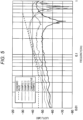
- FIG. 8 is a graph illustrating an insertion loss.
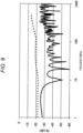
- FIG. 9 is a graph illustrating a reflection loss.
- broken lines indicate standard values.
- the characteristic impedance of the duplex twisted shielded cable according to Example 2 was maintained at around 100 ⁇ , and the standard value of 95 S2 or more and 105 S2 or less was satisfied.
- the duplex twisted shielded cable according to Example 2 had a small insertion loss in the entire frequency range of 1 MHz to 1000 MHz and the standard value was satisfied.
- the duplex twisted shielded cable according to Example 2 had a small reflection loss in the entire frequency range of 1 MHz to 1000 MHz and the standard value was satisfied.
- the metal foil shield 20 is attached longitudinally to the metal foil shield 20 to be provided therearound, trimming can be easily performed.
- the thickness of the film layer 21 of the metal foil shield 20 is 20 ⁇ m or less and the ellipticity is 0.90 or less, the metal foil shield 20 is brought into close contact with the two insulated electric wires 10 to a certain extent so that the position of the metal foil shield 20 with respect to the two insulated wires 10 is unlikely to be unstable, and deterioration of the transmission characteristics can be suppressed.
- the metal foil shield 20 is not in an excessively close contact with the two insulated wires 10, which contributes to prevention of a situation where the metal foil shield 20 easily breaks at the time of bending, and the deterioration of the transmission characteristics due to breakage of the metal foil shield 20 can be suppressed. Accordingly, it is possible to provide the duplex twisted shielded cable 1 that can be more easily trimmed and can suppress deterioration of the transmission characteristics.
- the thickness of the metal layer 23 is 20 ⁇ m or less, it is possible to suppress a situation in which it is difficult to achieve an ellipticity of 0.90 or less when the metal layer 23 is too thick.
- the wire harness WH of the embodiment it is possible to provide the wire harness WH that can be more easily trimmed and can suppress deterioration of the transmission characteristics.
- the metal foil shield 20 is disposed such that the metal layer 23 faces an outer side of the metal foil shield 20 in the duplex twisted shielded cable 1 in the above-described embodiments, the present disclosure is not limited thereto, and the metal foil shield 20 may face an inner side of the metal foil shield 20.
- the metal braid 30 is attached to a shielded connector.
- the attachment target may not be a shielded connector.
- a duplex twisted shielded cable (1) includes; two insulated wires (10) that are twisted together, each having a conductor (11) and an insulator (12) covering the conductor (11); a metal foil shield (20) provided around the two insulated wires (10); a metal braid (30) provided on an outer periphery of the metal foil shield (20); and a sheath (40) provided on an outer periphery of the metal braid (30).
- the metal foil shield (20) includes a PET film layer (21) and a metal layer (23).
- the PET film layer (21) has a thickness of 20 ⁇ m or less, an ellipticity of the PET film layer (21) is set to 0.75 or more and 0.90 or less, and the metal foil shield (20) is longitudinally attached to the two insulated wires (10).
- the metal layer (23) of the metal foil shield (20) may have a thickness of 20 ⁇ m or less.
- a wire harness may include: the duplex twisted shielded cable (1) according to the aspect 1 or 2; and another member (100) adjacent to the duplex twisted shielded cable (1).
Abstract
There are provided a duplex twisted shielded cable and wire harness, the duplex twisted shielded cable including; two insulated wires that are twisted together, each having a conductor and an insulator covering the conductor; a metal foil shield provided around the two insulated wires; a metal braid provided on an outer periphery of the metal foil shield; and a sheath provided on an outer periphery of the metal braid. The metal foil shield includes a PET film layer and a metal layer. The PET film layer has a thickness of 20 µm or less, an ellipticity of the PET film layer is set to 0.75 or more and 0.90 or less, and the metal foil shield is longitudinally attached to the two insulated wires.
Description
- The present disclosure relates to a duplex twisted shielded cable and a wire harness.
- In the related art, there has been proposed a duplex shielded cable for high-speed digital signal transmission for the purpose of improving characteristics of a leakage attenuation amount at the time when a differential signal is applied. The duplex shielded cable includes two electric wires, a metal foil shield provided around the electric wires, a metal braid on the metal foil shield, and a sheath provided on the metal braid. A signal to be transmitted in such a duplex shielded cable has a high frequency, and considering a skin effect and a return current, it is effective for the duplex shielded cable to have a metal foil shield having a smooth surface.
- Here, a shielded cable of multi-cores (three or more cores) has been proposed (for example, see
JP2015-072774A JP2003-132743A JP2015-153497A JP2015-072774A - A shielded cable disclosed in
JP2003-132743A - A shielded cable disclosed in
JP2015-153497A - In addition, the following shielded cables have been proposed as duplex or single-core shielded cables (see
JP2015-185527A JP2007-265797A JP2015-185527A - Further, a shielded cable disclosed in
JP2007-265797A - Here, in a shielded cable, it is preferable that a metal foil shield is easily trimmed at terminal processing.
- For this reason, the metal foil shield is preferably longitudinally attached to two insulated wires that are on an inner side, rather than spirally wound around two insulated wires.
- This is because, in the case of the spiral winding, it is difficult to trim a lower portion of overlapped metal foil shields at a wrap portion of the spirally wound metal foil shield. Therefore, in consideration of trimming, it can be said that longitudinal attachment is preferred for the metal foil shield.
- However, when the metal foil shield is longitudinally attached to two insulated wires, the metal foil shield is easily provided along the two insulated wires, that is, in a state in which the metal foil shield is not in close contact with the two insulated wires, and a position of the metal foil shield with respect to the insulated wires is unstable, and transmission characteristics are easily deteriorated.
- Therefore, in order to improve the transmission characteristics, it is conceivable to wind the metal foil shield around the two insulated wires so that the metal foil shield is in closer contact with the two insulated wires even if the metal foil shield is longitudinally attached. However, in a duplex twisted shielded cable in which two insulated wires are twisted, when a metal foil shield is brought into excessively close contact with the two insulated wires, the metal foil shield is likely to be broken due to a slight cable bending. That is, in a duplex parallel-shielded cable that is not twisted, since the two insulated wires are arranged in parallel, it can be expected, to a certain extent, that the insulated wires and a metal foil shield slip to one another when the cable is bent. On the other hand, in the case where the two insulated wires are twisted, even if slipping can be expected in a twist direction (spiral direction), an outer side in the bending is stretched in a cable longitudinal direction at the time of bending. For that reason, the stretch is in a direction different from the direction in which the slipping can be expected, and it cannot be expected the two insulated wires and the metal foil shield slip to one another, so that the metal foil shield is easily broken. Accordingly, in the duplex twisted shielded cable, when the metal foil shield is brought into an excessively close contact with the two insulated wires, there is a possibility that the metal foil shield is broken. Therefore, noise resistance is reduced to cause deterioration in the transmission characteristics eventually.
- The present disclosure provides a duplex twisted shielded cable and a wire harness that can be more easily trimmed and can suppress deterioration of transmission characteristics.
- According to an illustrative aspect of the present disclosure, a duplex twisted shielded cable includes; two insulated wires that are twisted together, each having a conductor and an insulator covering the conductor; a metal foil shield provided around the two insulated wires; a metal braid provided on an outer periphery of the metal foil shield; and a sheath provided on an outer periphery of the metal braid. The metal foil shield includes a PET film layer and a metal layer. The PET film layer has a thickness of 20 µm or less, an ellipticity of the PET film layer is set to 0.75 or more and 0.90 or less, and the metal foil shield is longitudinally attached to the two insulated wires.
- According to another illustrative aspect of the present disclosure, a wire harness includes: the duplex twisted shielded cable according to the above aspect; and another member adjacent to the duplex twisted shielded cable.
-
-
FIG. 1 is a perspective view of a wire harness including a duplex twisted shielded cable according to an embodiment of the present disclosure; -
FIG. 2 is a perspective view illustrating the duplex twisted shielded cable shown inFIG. 1 ; -
FIG. 3 is a cross-sectional view illustrating the duplex twisted shielded cable shown inFIG. 1 ; -
FIG. 4 is a table illustrating duplex twisted shielded cables according to Examples 1 to 3 and Comparative Example 1; -
FIG. 5 is a graph illustrating transmission characteristics of the duplex twisted shielded cables according to Examples 1 to 3 and Comparative Example 1; -
FIG. 6 is a graph illustrating correlation between a thickness of a film layer and an ellipticity of the duplex twisted shielded cables according to Examples 1 to 3 and Comparative Example 1; -
FIG. 7 is a graph illustrating the transmission characteristics and characteristic impedance of the duplex twisted shielded cable according to Example 2; -
FIG. 8 is a graph illustrating the transmission characteristics of the duplex twisted shielded cable according to Example 2, showing insertion loss; and -
FIG. 9 is a graph illustrating the transmission characteristics of the duplex twisted shielded cable according to Example 2, showing reflection loss. - Hereinafter, the present disclosure will be described with reference to preferred embodiments. It should be noted that the present disclosure is not limited to the following embodiments, and modifications can be appropriately made without departing from the gist of the present disclosure. In addition, in the embodiments described below, although there are portions in which illustration and description of a part of the configuration are omitted, it is needless to say that a publicly known or well-known technique is appropriately applied to the details of the omitted technique within a range in which no contradiction with the contents described below occurs.
-
FIG. 1 is a perspective view of a wire harness including a duplex twisted shielded cable according to an embodiment of the present disclosure. As illustrated inFIG. 1 , a wire harness WH includes a duplex twisted shieldedcable 1 and another cable (another member) 100. - The
other cable 100 is, for example, a thick electric wire such as a power line or a thin electric wire such as a signal line different from the power line, and includes aconductor 101 and aninsulator 102 covering a periphery of theconductor 101. A resin tape RT is wound around the duplex twisted shieldedcable 1 and theother cable 100, or a corrugated tube (not shown), a terminal (not shown), a connector, or the like is attached to the duplex twisted shieldedcable 1 and theother cable 100. -
FIG. 2 is a perspective view illustrating the duplex twisted shieldedcable 1 shown inFIG. 1 , andFIG. 3 is a cross-sectional view illustrating the duplex twisted shieldedcable 1 shown inFIG. 1 . As illustrated inFIGS. 2 and3 , the duplex twisted shieldedcable 1 includes two insulatedwires 10, ametal foil shield 20, ametal braid 30, and asheath 40. - The
insulated wires 10 each include aconductor 11 and aninsulator 12 on theconductor 11, and are twisted (twisted) so as to be helical with respect to each other. As theconductor 11, a soft copper wire, a silver-plated soft copper wire, a tin-plated soft copper wire, a tin-plated copper alloy wire, or the like is used. Although theconductor 11 is implemented by a twisted wire obtained by twisting two or more (specifically, seven) wires in the embodiment, the present disclosure is not particularly limited thereto. Theconductor 11 may be implemented by one single wire. Further, although a cross-sectional area of theconductor 11 is assumed to be 0.22 sq ("sq" is a unit for indicating square millimeter) or less, the present disclosure is not particularly limited thereto. - The
insulator 12 is a member covering theconductor 11. As theinsulator 12, polyethylene (PE), polypropylene (PP), or the like is used. Theinsulator 12 has, for example, a dielectric constant of 3.0 or less. Theinsulator 12 preferably has a thickness of 0.52 mm or less based on the following formula (1).
- Here, Z0 is a characteristic impedance and, for example, 100 S2 is substituted. In addition, εe is a dielectric constant, and for example, a value of 3.0 or less is substituted. Further, dw is a wire diameter of the wires constituting the
conductor 11, and is assumed to be 0.16 mm, for example. In addition, d is an outer diameter of theconductor 11, and is 0.48 mm when seven wires each having a wire diameter of 0.16 mm are twisted, ki is a conductor outer-diameter coefficient, and is 0.939 in the above example. B is a distance between centers of theconductors 11 of the twoinsulated wires 10. The thickness of theinsulator 12 is calculated by substituting the above values and the like into formula (1),and is preferably 0.52 mm or less. - The
metal foil shield 20 has a three-layer structure including a film layer (PET film layer) 21, anadhesive layer 22, and ametal layer 23, theadhesive layer 22 integrally bonding thefilm layer 21 and themetal layer 23. Thefilm layer 21 is a non-conductive resin film and is made of polyethylene terephthalate (PET) resin. Thefilm layer 21 is preferably a biaxially stretched film formed by stretching a resin film in two directions of a longitudinal direction and a lateral direction at a high temperature. This is because the biaxially stretched film can have high strength in the longitudinal direction and the lateral direction and is hard to break. In the embodiment, thefilm layer 21 has a thickness of 20 µm or less. - The
metal layer 23 is a conductive metal layer and is made of a metal such as copper or aluminum. In the embodiment, themetal layer 23 preferably has a thickness of 20 µm or less. In addition, from the viewpoint of ensuring shielding performance, themetal layer 23 preferably has a thickness of 8 µm or more when made of copper, and preferably has a thickness of 10 µm or more when made of aluminum. For various types of metals, when themetal layer 23 has a thickness of 10 µm or more, the shielding performance can be sufficiently exhibited. Further, themetal foil shield 20 is longitudinally attached on the twoinsulated wires 10 so that themetal layer 23 is on an outer side. - The
metal braid 30 is formed by weaving bundles of metal wires such as a soft copper wire, a silver-plated soft copper wire, a tin-plated soft copper wire, or a tin-plated copper alloy wire, each bundle including a plurality of the metal wires. The metal wire may be a plated fiber obtained by applying a metal plating on a fiber. Further, themetal braid 30 may be formed by weaving a flat bundle obtained by collectively applying a plating to a plurality of metal wires. - The
sheath 40 is an insulator that covers an outer periphery of themetal braid 30. Thesheath 40 is in a stuffing state on an outer peripheral side of themetal foil shield 20 and themetal braid 30. That is, thesheath 40 is provided in a so-called solid state rather than in a tube form having a void inside. By solid extrusion with respect to a component consisting of theinsulated wires 10, themetal foil shield 20, and themetal braid 30, thesheath 40 is provided around theinsulated wires 10, themetal foil shield 20, and themetal braid 30. Thesheath 40 is made of, for example, PE, PP, and polyvinyl chloride (PVC). Thesheath 40 is not limited to the solid state, and may be implemented in a tube shape and disposed in a state in which a void is provided at some parts with respect to theinner metal braid 30, or any other inclusion may be separately provided in the void. - Here, in the duplex twisted shielded
cable 1 according to the embodiment, the thickness of thefilm layer 21 is 20 µm or less, and the rigidity is suppressed to a certain extent. Therefore, when themetal foil shield 20 is longitudinally attached to the twoinsulated wires 10, themetal foil shield 20 can be wound to fit a shape of the twoinsulated wires 10 that are twisted. This can contribute to stabilizing the position of themetal foil shield 20 with respect to the twoinsulated wires 10. In particular, when the thickness of thefilm layer 21 is 20 µm or less, as long as themetal layer 23 is not excessively thick, themetal foil shield 20 can be wound such that an ellipticity (an ellipticity in a cross section orthogonal to the longitudinal direction, the same applying hereinafter) with respect to the twoinsulated wires 10 is 0.90 or less. - In addition, in the duplex twisted shielded
cable 1, themetal foil shield 20 is wound such that the ellipticity with respect to the twoinsulated wires 10 is 0.75 or more. Accordingly, in the duplex twisted shieldedcable 1, themetal foil shield 20 is not wound around the twoinsulated wires 10 in a state where themetal foil shield 20 is in an excessively close contact with the two insulatedelectric wires 10. - Next, examples and comparative examples of the duplex twisted shielded
cable 1 according to the embodiment will be described.FIG. 4 is a table illustrating duplex twisted shielded cables according to Examples 1 to 3 and Comparative Example 1. In the duplex twisted shielded cables according to Examples 1 to 3 and Comparative Example 1, a conductor was a twisted wire obtained by twisting seven soft copper wires together, and had a cross-sectional area of 0.13 sq. An outer diameter thereof was 0.48 mm. An insulator was made of a crosslinked polyolefin, and had an outer diameter of 1.22 mm as a result of covering the conductor. - An
outer shield 1 was formed of a metal foil shield in which a thickness of a metal layer was 10 µm, and was longitudinally attached with respect to two insulated wires. Anouter shield 2 was formed of a braided shield formed of a metal wire. A sheath was made of a flame-retardant polyolefin. With the above configuration, the duplex twisted shielded cables according to Examples 1 to 3 and Comparative Example 1 had a finished outer diameter of 3.8 mm. - In the metal foil shield serving as the
outer shield 1, a thickness of a PET layer (film layer) was 6 µm in Example 1, 12 µm in Example 2, 20 µm in Example 3, and 25 µm in Comparative Example 1. -
FIG. 5 is a graph illustrating transmission characteristics of the duplex twisted shielded cables according to Examples 1 to 3 and Comparative Example 1. As illustrated inFIG. 5 , regarding Examples 1 to 3, a result was shown that a standard value was satisfied in the entire frequency range of 0.01 GHz to 1 GHz. In contrast, regarding Comparative Example 1, a result was shown that the standard value was not satisfied in a range of more than 0.04 GHz to about 0.2 GHz. This is because an ellipticity was not 0.90 or less in Comparative Example 1. -
FIG. 6 is a graph illustrating correlation between the thickness of the film layer and an ellipticity of the duplex twisted shielded cables according to Examples 1 to 3 and Comparative Example 1. As illustrated inFIG. 6 , in Examples 1 to 3, when the thickness of the film layer was 6 µm, 12 µm, and 20 µm, the ellipticity was 0.75, 0.83, and 0.90, respectively. Therefore, the ellipticity was 0.90 or less in all examples, and it can be said that the metal foil shield was wound in a manner of conforming to a shape of the two insulated wires to some extent. Therefore, regarding the transmission characteristics, as illustrated inFIG. 5 , the standard value was satisfied. - On the other hand, in the duplex twisted shielded cable according to Comparative Example 1, the thickness of the film layer was 25 µm, and the ellipticity exceeded 0.90. Therefore, the metal foil shield was not wound in a manner of conforming to the shape of the two insulated wires, and regarding the transmission characteristics, a result was shown that the standard value was not satisfied as illustrated in
FIG. 5 . - In the example shown in
FIG. 6 , the thickness of the metal layer is 10 µm. However, although not shown, it was also found that, in a case where the thickness of the film layer was 20 µm, even if the thickness of the metal layer was 40 µm, there was no problem in setting the ellipticity to 0.90 or less by a winding method at the time of longitudinal attachment. In addition, it was also found that the thickness of the metal layer is preferably 20 µm or less in order to easily achieve the ellipticity of 0.90 or less. - In addition, the duplex twisted shielded cables according to Examples 1 to 3 and Comparative Example 2 (the thickness of the film layer in Comparative Example 1 was set to 4 µm in Comparative Example 2) were subjected to a 180° bending test. The 180° bending test is implemented under a condition where a weight W of 200g was suspended from one end (lower end) of the duplex twisted shielded cable, an upper portion (a portion at a slightly lower end side of an upper end) of the duplex twisted shielded cable was sandwiched between a pair of mandrel M having a diameter of 30 mm. Next, the other end (upper end) of the duplex twisted shielded cable was repeatedly bent along the mandrel M at a bending angle of 180°. In the repeated bending, the number of times of bending at the time when a resistance value of the metal foil shield increased by 10% was measured.
- As a result, the number of times of bending was about 400 in Example 1, about 500 in Example 2, and about 600 in Example 3, all exceeding 300. In contrast, regarding Comparative Example 2 in which the thickness of the film layer of the metal foil shield was set to 4 µm, the number of times of bending was about 200, which was less than 300. Therefore, when the ellipticity is less than 0.75, deterioration of noise resistance performance (deterioration of transmission characteristics) due to breakage of the metal foil shield was confirmed.
-
FIGS. 7 to 9 are graphs illustrating the transmission characteristics of the duplex twisted shielded cable according to Example 2.FIG. 7 is a graph illustrating a characteristic impedance.FIG. 8 is a graph illustrating an insertion loss.FIG. 9 is a graph illustrating a reflection loss. InFIGS. 7 to 9 , broken lines indicate standard values. - As illustrated in
FIG. 7 , the characteristic impedance of the duplex twisted shielded cable according to Example 2 was maintained at around 100 Ω, and the standard value of 95 S2 or more and 105 S2 or less was satisfied. - As illustrated in
FIG. 8 , the duplex twisted shielded cable according to Example 2 had a small insertion loss in the entire frequency range of 1 MHz to 1000 MHz and the standard value was satisfied. - Further, as illustrated in
FIG. 9 , the duplex twisted shielded cable according to Example 2 had a small reflection loss in the entire frequency range of 1 MHz to 1000 MHz and the standard value was satisfied. - In this way, according to the duplex twisted shielded
cable 1 of the embodiment, since themetal foil shield 20 is attached longitudinally to themetal foil shield 20 to be provided therearound, trimming can be easily performed. In addition, since the thickness of thefilm layer 21 of themetal foil shield 20 is 20 µm or less and the ellipticity is 0.90 or less, themetal foil shield 20 is brought into close contact with the two insulatedelectric wires 10 to a certain extent so that the position of themetal foil shield 20 with respect to the twoinsulated wires 10 is unlikely to be unstable, and deterioration of the transmission characteristics can be suppressed. Further, since the ellipticity of themetal foil shield 20 is 0.75 or more, themetal foil shield 20 is not in an excessively close contact with the twoinsulated wires 10, which contributes to prevention of a situation where themetal foil shield 20 easily breaks at the time of bending, and the deterioration of the transmission characteristics due to breakage of themetal foil shield 20 can be suppressed. Accordingly, it is possible to provide the duplex twisted shieldedcable 1 that can be more easily trimmed and can suppress deterioration of the transmission characteristics. - In addition, since the thickness of the
metal layer 23 is 20 µm or less, it is possible to suppress a situation in which it is difficult to achieve an ellipticity of 0.90 or less when themetal layer 23 is too thick. - In addition, according to the wire harness WH of the embodiment, it is possible to provide the wire harness WH that can be more easily trimmed and can suppress deterioration of the transmission characteristics.
- Although the present disclosure has been described above based on the embodiments, the present disclosure is not limited to the above embodiments. Modifications may be made without departing from the gist of the present disclosure and publicly known or well-known techniques may be appropriately combined.
- For example, although the
metal foil shield 20 is disposed such that themetal layer 23 faces an outer side of themetal foil shield 20 in the duplex twisted shieldedcable 1 in the above-described embodiments, the present disclosure is not limited thereto, and themetal foil shield 20 may face an inner side of themetal foil shield 20. - In addition, in the duplex twisted shielded
cable 1 according to the embodiment, it is assumed that themetal braid 30 is attached to a shielded connector. Alternatively, the attachment target may not be a shielded connector. - According to a first aspect of the present disclosure, a duplex twisted shielded cable (1) includes; two insulated wires (10) that are twisted together, each having a conductor (11) and an insulator (12) covering the conductor (11); a metal foil shield (20) provided around the two insulated wires (10); a metal braid (30) provided on an outer periphery of the metal foil shield (20); and a sheath (40) provided on an outer periphery of the metal braid (30). The metal foil shield (20) includes a PET film layer (21) and a metal layer (23). The PET film layer (21) has a thickness of 20 µm or less, an ellipticity of the PET film layer (21) is set to 0.75 or more and 0.90 or less, and the metal foil shield (20) is longitudinally attached to the two insulated wires (10).
- According to a second aspect of the present disclosure, the metal layer (23) of the metal foil shield (20) may have a thickness of 20 µm or less.
- According to a third aspect of the present disclosure, a wire harness (WH) may include: the duplex twisted shielded cable (1) according to the
aspect - According to the present disclosure, it is possible to provide a duplex twisted shielded cable and a wire harness that can be more easily trimmed and can suppress deterioration of transmission characteristics.
Claims (3)
- A duplex twisted shielded cable (1) comprising;two insulated wires (10) that are twisted together, each having a conductor (11) and an insulator (12) covering the conductor (11);a metal foil shield (20) provided around the two insulated wires (10);a metal braid (30) provided on an outer periphery of the metal foil shield (20); and a sheath (40) provided on an outer periphery of the metal braid (30), whereinthe metal foil shield (20) includes a PET film layer (21) and a metal layer (23), and the PET film layer (21) has a thickness of 20 µm or less, an ellipticity of the PET film layer (21) is set to 0.75 or more and 0.90 or less, and the metal foil shield (20) is longitudinally attached to the two insulated wires (10).
- The duplex twisted shielded cable (1) according to claim 1, wherein
the metal layer (23) of the metal foil shield (20) has a thickness of 20 µm or less. - A wire harness (WH) comprising:the duplex twisted shielded cable (1) according to claim 1 or 2; andanother member (100) adjacent to the duplex twisted shielded cable (1).
Applications Claiming Priority (1)
| Application Number | Priority Date | Filing Date | Title |
|---|---|---|---|
| JP2022098651A JP2024000097A (en) | 2022-06-20 | 2022-06-20 | Two-core twisted shielded cable and wire harness |
Publications (1)
| Publication Number | Publication Date |
|---|---|
| EP4297047A1 true EP4297047A1 (en) | 2023-12-27 |
Family
ID=86383015
Family Applications (1)
| Application Number | Title | Priority Date | Filing Date |
|---|---|---|---|
| EP23173325.4A Pending EP4297047A1 (en) | 2022-06-20 | 2023-05-15 | Duplex twisted shielded cable, and wire harness |
Country Status (4)
| Country | Link |
|---|---|
| US (1) | US20230411043A1 (en) |
| EP (1) | EP4297047A1 (en) |
| JP (1) | JP2024000097A (en) |
| CN (1) | CN117275808A (en) |
Citations (7)
| Publication number | Priority date | Publication date | Assignee | Title |
|---|---|---|---|---|
| JP2003132743A (en) | 2001-10-25 | 2003-05-09 | Sumitomo Electric Ind Ltd | Cable for signal transfer, terminal device, and data transfer method using these |
| JP2007265797A (en) | 2006-03-28 | 2007-10-11 | Sumitomo Electric Ind Ltd | Coaxial cable and its manufacturing method |
| JP2015072774A (en) | 2013-10-02 | 2015-04-16 | 住友電気工業株式会社 | Multicore cable and production method thereof |
| JP2015153497A (en) | 2014-02-12 | 2015-08-24 | 日立金属株式会社 | Shield cable |
| JP2015185527A (en) | 2014-03-26 | 2015-10-22 | 住友電気工業株式会社 | Two-core parallel electric wire |
| WO2019058437A1 (en) * | 2017-09-19 | 2019-03-28 | 株式会社オートネットワーク技術研究所 | Shielded communication cable |
| US20190341171A1 (en) * | 2016-03-31 | 2019-11-07 | Autonetworks Technologies, Ltd. | Shielded communication cable |
-
2022
- 2022-06-20 JP JP2022098651A patent/JP2024000097A/en active Pending
-
2023
- 2023-05-15 CN CN202310542617.5A patent/CN117275808A/en active Pending
- 2023-05-15 EP EP23173325.4A patent/EP4297047A1/en active Pending
- 2023-05-15 US US18/317,857 patent/US20230411043A1/en active Pending
Patent Citations (7)
| Publication number | Priority date | Publication date | Assignee | Title |
|---|---|---|---|---|
| JP2003132743A (en) | 2001-10-25 | 2003-05-09 | Sumitomo Electric Ind Ltd | Cable for signal transfer, terminal device, and data transfer method using these |
| JP2007265797A (en) | 2006-03-28 | 2007-10-11 | Sumitomo Electric Ind Ltd | Coaxial cable and its manufacturing method |
| JP2015072774A (en) | 2013-10-02 | 2015-04-16 | 住友電気工業株式会社 | Multicore cable and production method thereof |
| JP2015153497A (en) | 2014-02-12 | 2015-08-24 | 日立金属株式会社 | Shield cable |
| JP2015185527A (en) | 2014-03-26 | 2015-10-22 | 住友電気工業株式会社 | Two-core parallel electric wire |
| US20190341171A1 (en) * | 2016-03-31 | 2019-11-07 | Autonetworks Technologies, Ltd. | Shielded communication cable |
| WO2019058437A1 (en) * | 2017-09-19 | 2019-03-28 | 株式会社オートネットワーク技術研究所 | Shielded communication cable |
Non-Patent Citations (1)
| Title |
|---|
| TATUM JEREMY: "2.2: The Ellipse - Physics LibreTexts", 22 May 2022 (2022-05-22), XP093093160, Retrieved from the Internet <URL:https://phys.libretexts.org/Bookshelves/Astronomy__Cosmology/Celestial_Mechanics_(Tatum)/02:_Conic_Sections/2.02:_The_Ellipse> [retrieved on 20231019] * |
Also Published As
| Publication number | Publication date |
|---|---|
| CN117275808A (en) | 2023-12-22 |
| JP2024000097A (en) | 2024-01-05 |
| US20230411043A1 (en) | 2023-12-21 |
Similar Documents
| Publication | Publication Date | Title |
|---|---|---|
| EP1607985B1 (en) | Multi-pair data cable with configurable core filling and pair separation | |
| WO2004107361A1 (en) | Multi-pair data cable with configurable core filing and pair separation | |
| HU225606B1 (en) | High performance data cable | |
| US20180268965A1 (en) | Data cable for high speed data transmissions and method of manufacturing the data cable | |
| CN111937094B (en) | Multi-core cable | |
| EP4297047A1 (en) | Duplex twisted shielded cable, and wire harness | |
| US20190096546A1 (en) | 2-core shielded cable and wire harness | |
| US11508497B2 (en) | Communication cable and wire harness | |
| JP7407627B2 (en) | composite cable | |
| US11158439B2 (en) | Shielded two-core electric wire routing structure which can be rerouted by bent-twisting the electric wire at a number of points per unit length | |
| JP7339042B2 (en) | Differential transmission cable and wire harness | |
| US20240079161A1 (en) | Two-core twisted shielded cable and wire harness | |
| EP4297048A1 (en) | Duplex twisted shielded cable, and wire harness | |
| KR20160000286U (en) | Multicore cable | |
| CN111968787B (en) | Bend resistant communications cable and harness | |
| EP3905281B1 (en) | Communication cable and wire harness | |
| JPH11111078A (en) | Interface cable | |
| US20220285049A1 (en) | Signal transmission cable | |
| JP2023067141A (en) | Electric wire for communication | |
| CN116805541A (en) | Twisted pair wire with shielding part | |
| JP2020107451A (en) | Shielded electric wire and wire harness |
Legal Events
| Date | Code | Title | Description |
|---|---|---|---|
| PUAI | Public reference made under article 153(3) epc to a published international application that has entered the european phase |
Free format text: ORIGINAL CODE: 0009012 |
|
| STAA | Information on the status of an ep patent application or granted ep patent |
Free format text: STATUS: REQUEST FOR EXAMINATION WAS MADE |
|
| 17P | Request for examination filed |
Effective date: 20230515 |
|
| AK | Designated contracting states |
Kind code of ref document: A1 Designated state(s): AL AT BE BG CH CY CZ DE DK EE ES FI FR GB GR HR HU IE IS IT LI LT LU LV MC ME MK MT NL NO PL PT RO RS SE SI SK SM TR |
|
| STAA | Information on the status of an ep patent application or granted ep patent |
Free format text: STATUS: EXAMINATION IS IN PROGRESS |
|
| 17Q | First examination report despatched |
Effective date: 20240228 |