EP4296979A2 - Anpassung einer grafikdarstellung auf basis des gesichtsausdrucks - Google Patents
Anpassung einer grafikdarstellung auf basis des gesichtsausdrucks Download PDFInfo
- Publication number
- EP4296979A2 EP4296979A2 EP23208421.0A EP23208421A EP4296979A2 EP 4296979 A2 EP4296979 A2 EP 4296979A2 EP 23208421 A EP23208421 A EP 23208421A EP 4296979 A2 EP4296979 A2 EP 4296979A2
- Authority
- EP
- European Patent Office
- Prior art keywords
- graphics
- user
- memory
- focus
- facial expression
- Prior art date
- Legal status (The legal status is an assumption and is not a legal conclusion. Google has not performed a legal analysis and makes no representation as to the accuracy of the status listed.)
- Withdrawn
Links
Images













Classifications
-
- G—PHYSICS
- G06—COMPUTING OR CALCULATING; COUNTING
- G06F—ELECTRIC DIGITAL DATA PROCESSING
- G06F3/00—Input arrangements for transferring data to be processed into a form capable of being handled by the computer; Output arrangements for transferring data from processing unit to output unit, e.g. interface arrangements
- G06F3/01—Input arrangements or combined input and output arrangements for interaction between user and computer
- G06F3/011—Arrangements for interaction with the human body, e.g. for user immersion in virtual reality
- G06F3/012—Head tracking input arrangements
-
- G—PHYSICS
- G06—COMPUTING OR CALCULATING; COUNTING
- G06T—IMAGE DATA PROCESSING OR GENERATION, IN GENERAL
- G06T1/00—General purpose image data processing
- G06T1/20—Processor architectures; Processor configuration, e.g. pipelining
-
- G—PHYSICS
- G06—COMPUTING OR CALCULATING; COUNTING
- G06F—ELECTRIC DIGITAL DATA PROCESSING
- G06F3/00—Input arrangements for transferring data to be processed into a form capable of being handled by the computer; Output arrangements for transferring data from processing unit to output unit, e.g. interface arrangements
- G06F3/01—Input arrangements or combined input and output arrangements for interaction between user and computer
- G06F3/011—Arrangements for interaction with the human body, e.g. for user immersion in virtual reality
-
- G—PHYSICS
- G06—COMPUTING OR CALCULATING; COUNTING
- G06F—ELECTRIC DIGITAL DATA PROCESSING
- G06F3/00—Input arrangements for transferring data to be processed into a form capable of being handled by the computer; Output arrangements for transferring data from processing unit to output unit, e.g. interface arrangements
- G06F3/01—Input arrangements or combined input and output arrangements for interaction between user and computer
- G06F3/011—Arrangements for interaction with the human body, e.g. for user immersion in virtual reality
- G06F3/013—Eye tracking input arrangements
-
- G—PHYSICS
- G06—COMPUTING OR CALCULATING; COUNTING
- G06F—ELECTRIC DIGITAL DATA PROCESSING
- G06F3/00—Input arrangements for transferring data to be processed into a form capable of being handled by the computer; Output arrangements for transferring data from processing unit to output unit, e.g. interface arrangements
- G06F3/01—Input arrangements or combined input and output arrangements for interaction between user and computer
- G06F3/03—Arrangements for converting the position or the displacement of a member into a coded form
- G06F3/033—Pointing devices displaced or positioned by the user, e.g. mice, trackballs, pens or joysticks; Accessories therefor
- G06F3/0346—Pointing devices displaced or positioned by the user, e.g. mice, trackballs, pens or joysticks; Accessories therefor with detection of the device orientation or free movement in a three-dimensional [3D] space, e.g. 3D mice, 6-DOF [six degrees of freedom] pointers using gyroscopes, accelerometers or tilt-sensors
-
- G—PHYSICS
- G06—COMPUTING OR CALCULATING; COUNTING
- G06F—ELECTRIC DIGITAL DATA PROCESSING
- G06F3/00—Input arrangements for transferring data to be processed into a form capable of being handled by the computer; Output arrangements for transferring data from processing unit to output unit, e.g. interface arrangements
- G06F3/01—Input arrangements or combined input and output arrangements for interaction between user and computer
- G06F3/048—Interaction techniques based on graphical user interfaces [GUI]
-
- G—PHYSICS
- G06—COMPUTING OR CALCULATING; COUNTING
- G06T—IMAGE DATA PROCESSING OR GENERATION, IN GENERAL
- G06T1/00—General purpose image data processing
- G06T1/60—Memory management
-
- G—PHYSICS
- G06—COMPUTING OR CALCULATING; COUNTING
- G06V—IMAGE OR VIDEO RECOGNITION OR UNDERSTANDING
- G06V40/00—Recognition of biometric, human-related or animal-related patterns in image or video data
- G06V40/10—Human or animal bodies, e.g. vehicle occupants or pedestrians; Body parts, e.g. hands
- G06V40/16—Human faces, e.g. facial parts, sketches or expressions
- G06V40/174—Facial expression recognition
- G06V40/176—Dynamic expression
-
- G—PHYSICS
- G06—COMPUTING OR CALCULATING; COUNTING
- G06F—ELECTRIC DIGITAL DATA PROCESSING
- G06F2203/00—Indexing scheme relating to G06F3/00 - G06F3/048
- G06F2203/01—Indexing scheme relating to G06F3/01
- G06F2203/011—Emotion or mood input determined on the basis of sensed human body parameters such as pulse, heart rate or beat, temperature of skin, facial expressions, iris, voice pitch, brain activity patterns
-
- G—PHYSICS
- G06—COMPUTING OR CALCULATING; COUNTING
- G06F—ELECTRIC DIGITAL DATA PROCESSING
- G06F2203/00—Indexing scheme relating to G06F3/00 - G06F3/048
- G06F2203/048—Indexing scheme relating to G06F3/048
- G06F2203/04806—Zoom, i.e. interaction techniques or interactors for controlling the zooming operation
Definitions
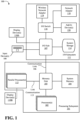
- the I/O hub 107 can enable a display controller, which may be included in the one or more processor(s) 102, to provide outputs to one or more display device(s) 110A.
- the one or more display device(s) 110A coupled with the I/O hub 107 can include a local, internal, or embedded display device.
- a system storage unit 114 can connect to the I/O hub 107 to provide a storage mechanism for the computing system 100.
- An I/O switch 116 can be used to provide an interface mechanism to enable connections between the I/O hub 107 and other components, such as a network adapter 118 and/or wireless network adapter 119 that may be integrated into the platform, and various other devices that can be added via one or more add-in device(s) 120.
- the network adapter 118 can be an Ethernet adapter or another wired network adapter.
- the wireless network adapter 119 can include one or more of a Wi-Fi, Bluetooth, near field communication (NFC), or other network device that includes one or more wireless radios.
- the computing system 100 can include other components not explicitly shown, including USB or other port connections, optical storage drives, video capture devices, and the like, may also be connected to the I/O hub 107.
- Communication paths interconnecting the various components in FIG. 1 may be implemented using any suitable protocols, such as PCI (Peripheral Component Interconnect) based protocols (e.g., PCI-Express), or any other bus or point-to-point communication interfaces and/or protocol(s), such as the NVLink high-speed interconnect, or interconnect protocols known in the art.
- PCI Peripheral Component Interconnect
- PCI-Express PCI-Express
- NVLink high-speed interconnect, or interconnect protocols known in the art.
- connection topology including the number and arrangement of bridges, the number of processor(s) 102, and the number of parallel processor(s) 112, may be modified as desired.
- system memory 104 is connected to the processor(s) 102 directly rather than through a bridge, while other devices communicate with system memory 104 via the memory hub 105 and the processor(s) 102.
- the parallel processor(s) 112 are connected to the I/O hub 107 or directly to one of the one or more processor(s) 102, rather than to the memory hub 105.
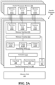
- FIG. 2A illustrates a parallel processor 200, according to an embodiment.
- the various components of the parallel processor 200 may be implemented using one or more integrated circuit devices, such as programmable processors, application specific integrated circuits (ASICs), or field programmable gate arrays (FPGA).
- the illustrated parallel processor 200 is a variant of the one or more parallel processor(s) 112 shown in FIG. 1 , according to an embodiment.
- the parallel processor 200 includes a parallel processing unit 202.
- the parallel processing unit includes an I/O unit 204 that enables communication with other devices, including other instances of the parallel processing unit 202.
- the I/O unit 204 may be directly connected to other devices.
- the I/O unit 204 connects with other devices via the use of a hub or switch interface, such as memory hub 105.
- the connections between the memory hub 105 and the I/O unit 204 form a communication link 113.
- the I/O unit 204 connects with a host interface 206 and a memory crossbar 216, where the host interface 206 receives commands directed to performing processing operations and the memory crossbar 216 receives commands directed to performing memory operations.
- the host interface 206 can direct work operations to perform those commands to a front end 208.
- the front end 208 couples with a scheduler 210, which is configured to distribute commands or other work items to a processing cluster array 212.
- the scheduler 210 ensures that the processing cluster array 212 is properly configured and in a valid state before tasks are distributed to the processing clusters of the processing cluster array 212.
- the scheduler 210 is implemented via firmware logic executing on a microcontroller.
- the microcontroller implemented scheduler 210 is configurable to perform complex scheduling and work distribution operations at coarse and fine granularity, enabling rapid preemption and context switching of threads executing on the processing array 212.
- the host software can prove workloads for scheduling on the processing array 212 via one of multiple graphics processing doorbells. The workloads can then be automatically distributed across the processing array 212 by the scheduler 210 logic within the scheduler microcontroller.
- the processing cluster array 212 can include up to "N" processing clusters (e.g., cluster 214A, cluster 214B, through cluster 214N). Each cluster 214A-214N of the processing cluster array 212 can execute a large number of concurrent threads.
- the scheduler 210 can allocate work to the clusters 214A-214N of the processing cluster array 212 using various scheduling and/or work distribution algorithms, which may vary depending on the workload arising for each type of program or computation. The scheduling can be handled dynamically by the scheduler 210, or can be assisted in part by compiler logic during compilation of program logic configured for execution by the processing cluster array 212. In one embodiment, different clusters 214A-214N of the processing cluster array 212 can be allocated for processing different types of programs or for performing different types of computations.
- the processing cluster array 212 can receive processing tasks to be executed via the scheduler 210, which receives commands defining processing tasks from front end 208.
- processing tasks can include indices of data to be processed, e.g., surface (patch) data, primitive data, vertex data, and/or pixel data, as well as state parameters and commands defining how the data is to be processed (e.g., what program is to be executed).
- the scheduler 210 may be configured to fetch the indices corresponding to the tasks or may receive the indices from the front end 208.
- the front end 208 can be configured to ensure the processing cluster array 212 is configured to a valid state before the workload specified by incoming command buffers (e.g., batch-buffers, push buffers, etc.) is initiated.
- incoming command buffers e.g., batch-buffers, push buffers, etc.
- Each of the one or more instances of the parallel processing unit 202 can couple with parallel processor memory 222.
- the parallel processor memory 222 can be accessed via the memory crossbar 216, which can receive memory requests from the processing cluster array 212 as well as the I/O unit 204.
- the memory crossbar 216 can access the parallel processor memory 222 via a memory interface 218.
- the memory interface 218 can include multiple partition units (e.g., partition unit 220A, partition unit 220B, through partition unit 220N) that can each couple to a portion (e.g., memory unit) of parallel processor memory 222.
- the memory units 224A-224N can include various types of memory devices, including dynamic random access memory (DRAM) or graphics random access memory, such as synchronous graphics random access memory (SGRAM), including graphics double data rate (GDDR) memory.
- the memory units 224A-224N may also include 3D stacked memory, including but not limited to high bandwidth memory (HBM).
- Render targets such as frame buffers or texture maps may be stored across the memory units 224A-224N, allowing partition units 220A-220N to write portions of each render target in parallel to efficiently use the available bandwidth of parallel processor memory 222.
- a local instance of the parallel processor memory 222 may be excluded in favor of a unified memory design that utilizes system memory in conjunction with local cache memory.
- FIG. 2B is a block diagram of a partition unit 220, according to an embodiment.
- the partition unit 220 is an instance of one of the partition units 220A-220N of FIG. 2A .
- the partition unit 220 includes an L2 cache 221, a frame buffer interface 225, and a ROP 226 (raster operations unit).
- the L2 cache 221 is a read/write cache that is configured to perform load and store operations received from the memory crossbar 216 and ROP 226. Read misses and urgent write-back requests are output by L2 cache 221 to frame buffer interface 225 for processing. Updates can also be sent to the frame buffer via the frame buffer interface 225 for processing.
- the frame buffer interface 225 interfaces with one of the memory units in parallel processor memory, such as the memory units 224A-224N of FIG. 2 (e.g., within parallel processor memory 222).
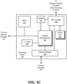
- Operation of the processing cluster 214 can be controlled via a pipeline manager 232 that distributes processing tasks to SIMT parallel processors.
- the pipeline manager 232 receives instructions from the scheduler 210 of Fig. 2 and manages execution of those instructions via a graphics multiprocessor 234 and/or a texture unit 236.
- the illustrated graphics multiprocessor 234 is an exemplary instance of a SIMT parallel processor. However, various types of SIMT parallel processors of differing architectures may be included within the processing cluster 214.
- One or more instances of the graphics multiprocessor 234 can be included within a processing cluster 214.
- the graphics multiprocessor 234 can process data and a data crossbar 240 can be used to distribute the processed data to one of multiple possible destinations, including other shader units.
- the pipeline manager 232 can facilitate the distribution of processed data by specifying destinations for processed data to be distributed via the data crossbar 240.
- a processing cluster 214 may be configured such that each graphics multiprocessor 234 is coupled to a texture unit 236 for performing texture mapping operations, e.g., determining texture sample positions, reading texture data, and filtering the texture data.
- Texture data is read from an internal texture L1 cache (not shown) or in some embodiments from the L1 cache within graphics multiprocessor 234 and is fetched from an L2 cache, local parallel processor memory, or system memory, as needed.
- Each graphics multiprocessor 234 outputs processed tasks to the data crossbar 240 to provide the processed task to another processing cluster 214 for further processing or to store the processed task in an L2 cache, local parallel processor memory, or system memory via the memory crossbar 216.
- FIG. 2D shows a graphics multiprocessor 234, according to one embodiment.
- the graphics multiprocessor 234 couples with the pipeline manager 232 of the processing cluster 214.
- the graphics multiprocessor 234 has an execution pipeline including but not limited to an instruction cache 252, an instruction unit 254, an address mapping unit 256, a register file 258, one or more general purpose graphics processing unit (GPGPU) cores 262, and one or more load/store units 266.
- the GPGPU cores 262 and load/store units 266 are coupled with cache memory 272 and shared memory 270 via a memory and cache interconnect 268.
- the instruction cache 252 receives a stream of instructions to execute from the pipeline manager 232.
- the instructions are cached in the instruction cache 252 and dispatched for execution by the instruction unit 254.
- the instruction unit 254 can dispatch instructions as thread groups (e.g., warps), with each thread of the thread group assigned to a different execution unit within GPGPU core 262.
- An instruction can access any of a local, shared, or global address space by specifying an address within a unified address space.
- the address mapping unit 256 can be used to translate addresses in the unified address space into a distinct memory address that can be accessed by the load/store units 266.
- the GPGPU cores 262 include SIMD logic capable of performing a single instruction on multiple sets of data.
- GPGPU cores 262 can physically execute SIMD4, SIMD8, and SIMD16 instructions and logically execute SIMD1, SIMD2, and SIMD32 instructions.
- the SIMD instructions for the GPGPU cores can be generated at compile time by a shader compiler or automatically generated when executing programs written and compiled for single program multiple data (SPMD) or SIMT architectures. Multiple threads of a program configured for the SIMT execution model can executed via a single SIMD instruction. For example and in one embodiment, eight SIMT threads that perform the same or similar operations can be executed in parallel via a single SIMD8 logic unit.
- each multi-core processor 405-406 is communicatively coupled to a processor memory 401-402, via memory interconnects 430-431, respectively, and each GPU 410-413 is communicatively coupled to GPU memory 420-423 over GPU memory interconnects 450-453, respectively.
- the memory interconnects 430-431 and 450-453 may utilize the same or different memory access technologies.
- FIG. 4B illustrates additional details for an interconnection between a multi-core processor 407 and a graphics acceleration module 446 in accordance with one embodiment.
- the graphics acceleration module 446 may include one or more GPU chips integrated on a line card which is coupled to the processor 407 via the high-speed link 440. Alternatively, the graphics acceleration module 446 may be integrated on the same package or chip as the processor 407.
- the illustrated processor 407 includes a plurality of cores 460A-460D, each with a translation lookaside buffer 461A-461D and one or more caches 462A-462D.
- the cores may include various other components for executing instructions and processing data which are not illustrated to avoid obscuring the underlying principles of the invention (e.g., instruction fetch units, branch prediction units, decoders, execution units, reorder buffers, etc.).
- the caches 462A-462D may comprise level 1 (L1) and level 2 (L2) caches.
- one or more shared caches 426 may be included in the caching hierarchy and shared by sets of the cores 460A-460D.
- a set of registers 445 store context data for threads executed by the graphics processing engines 431-432, N and a context management circuit 448 manages the thread contexts.
- the context management circuit 448 may perform save and restore operations to save and restore contexts of the various threads during contexts switches (e.g., where a first thread is saved and a second thread is stored so that the second thread can be execute by a graphics processing engine).
- the context management circuit 448 may store current register values to a designated region in memory (e.g., identified by a context pointer). It may then restore the register values when returning to the context.
- an interrupt management circuit 447 receives and processes interrupts received from system devices.
- virtual/effective addresses from a graphics processing engine 431 are translated to real/physical addresses in system memory 411 by the MMU 439.
- One embodiment of the accelerator integration circuit 436 supports multiple (e.g., 4, 8, 16) graphics accelerator modules 446 and/or other accelerator devices.
- the graphics accelerator module 446 may be dedicated to a single application executed on the processor 407 or may be shared between multiple applications.
- a virtualized graphics execution environment is presented in which the resources of the graphics processing engines 431-432, N are shared with multiple applications or virtual machines (VMs).
- the resources may be subdivided into "slices" which are allocated to different VMs and/or applications based on the processing requirements and priorities associated with the VMs and/or applications.
- one or more graphics memories 433-434, M are coupled to each of the graphics processing engines 431-432, N, respectively.
- the graphics memories 433-434, M store instructions and data being processed by each of the graphics processing engines 431-432, N.
- the graphics memories 433-434, M may be volatile memories such as DRAMs (including stacked DRAMs), GDDR memory (e.g., GDDR5, GDDR6), or HBM, and/or may be non-volatile memories such as 3D XPoint or Nano-Ram.
- biasing techniques are used to ensure that the data stored in graphics memories 433-434, M is data which will be used most frequently by the graphics processing engines 431-432, N and preferably not used by the cores 460A-460D (at least not frequently).
- the biasing mechanism attempts to keep data needed by the cores (and preferably not the graphics processing engines 431-432, N) within the caches 462A-462D, 456 of the cores and system memory 411.
- FIG. 4C illustrates another embodiment in which the accelerator integration circuit 436 is integrated within the processor 407.
- the graphics processing engines 431-432, N communicate directly over the high-speed link 440 to the accelerator integration circuit 436 via interface 437 and interface 435 (which, again, may be utilize any form of bus or interface protocol).
- the accelerator integration circuit 436 may perform the same operations as those described with respect to FIG. 4B , but potentially at a higher throughput given its close proximity to the coherency bus 462 and caches 462A-462D, 426.
- One embodiment supports different programming models including a dedicated-process programming model (no graphics acceleration module virtualization) and shared programming models (with virtualization).
- the latter may include programming models which are controlled by the accelerator integration circuit 436 and programming models which are controlled by the graphics acceleration module 446.
- graphics processing engines 431-432, N are dedicated to a single application or process under a single operating system.
- the single application can funnel other application requests to the graphics engines 431-432, N, providing virtualization within a VM/partition.
- the graphics processing engines 431-432, N may be shared by multiple VM/application partitions.
- the shared models require a system hypervisor to virtualize the graphics processing engines 431-432, N to allow access by each operating system.
- the graphics processing engines 431-432, N are owned by the operating system. In both cases, the operating system can virtualize the graphics processing engines 431-432, N to provide access to each process or application.
- FIG. 4D illustrates an exemplary accelerator integration slice 490.
- a "slice” comprises a specified portion of the processing resources of the accelerator integration circuit 436.
- Application effective address space 482 within system memory 411 stores process elements 483.
- the process elements 483 are stored in response to GPU invocations 481 from applications 480 executed on the processor 407.
- a process element 483 contains the process state for the corresponding application 480.
- a work descriptor (WD) 484 contained in the process element 483 can be a single job requested by an application or may contain a pointer to a queue of jobs. In the latter case, the WD 484 is a pointer to the job request queue in the application's address space 482.
- the graphics acceleration module 446 and/or the individual graphics processing engines 431-432, N can be shared by all or a subset of the processes in the system.
- Embodiments of the invention include an infrastructure for setting up the process state and sending a WD 484 to a graphics acceleration module 446 to start a job in a virtualized environment.
- the dedicated-process programming model is implementation-specific.
- a single process owns the graphics acceleration module 446 or an individual graphics processing engine 431. Because the graphics acceleration module 446 is owned by a single process, the hypervisor initializes the accelerator integration circuit 436 for the owning partition and the operating system initializes the accelerator integration circuit 436 for the owning process at the time when the graphics acceleration module 446 is assigned.
- a WD fetch unit 491 in the accelerator integration slice 490 fetches the next WD 484 which includes an indication of the work to be done by one of the graphics processing engines of the graphics acceleration module 446.
- Data from the WD 484 may be stored in registers 445 and used by the MMU 439, interrupt management circuit 447 and/or context management circuit 446 as illustrated.
- the MMU 439 includes segment/page walk circuitry for accessing segment/page tables 486 within the OS virtual address space 485.
- the interrupt management circuit 447 may process interrupt events 492 received from the graphics acceleration module 446.
- an effective address 493 generated by a graphics processing engine 431-432, N is translated to a real address by the MMU 439.
- the same set of registers 445 are duplicated for each graphics processing engine 431-432, N and/or graphics acceleration module 446 and may be initialized by the hypervisor or operating system. Each of these duplicated registers may be included in an accelerator integration slice 490. Exemplary registers that may be initialized by the hypervisor are shown in Table 1. Table 1 - Hypervisor Initialized Registers 1 Slice Control Register 2 Real Address (RA) Scheduled Processes Area Pointer 3 Authority Mask Override Register 4 Interrupt Vector Table Entry Offset 5 Interrupt Vector Table Entry Limit 6 State Register 7 Logical Partition ID 8 Real address (RA) Hypervisor Accelerator Utilization Record Pointer 9 Storage Description Register
- Table 2 Exemplary registers that may be initialized by the operating system are shown in Table 2.
- Table 2 Operating System Initialized Registers 1 Process and Thread Identification 2 Effective Address (EA) Context Save/Restore Pointer 3 Virtual Address (VA) Accelerator Utilization Record Pointer 4 Virtual Address (VA) Storage Segment Table Pointer 5 Authority Mask 6 Work descriptor
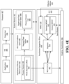
- FIG. 4E illustrates additional details for one embodiment of a shared model.
- This embodiment includes a hypervisor real address space 498 in which a process element list 499 is stored.
- the hypervisor real address space 498 is accessible via a hypervisor 496 which virtualizes the graphics acceleration module engines for the operating system 495.
- the shared programming models allow for all or a subset of processes from all or a subset of partitions in the system to use a graphics acceleration module 446.
- the system hypervisor 496 owns the graphics acceleration module 446 and makes its function available to all operating systems 495.
- the graphics acceleration module 446 may adhere to the following requirements: 1) An application's job request must be autonomous (that is, the state does not need to be maintained between jobs), or the graphics acceleration module 446 must provide a context save and restore mechanism. 2) An application's job request is guaranteed by the graphics acceleration module 446 to complete in a specified amount of time, including any translation faults, or the graphics acceleration module 446 provides the ability to preempt the processing of the job. 3) The graphics acceleration module 446 must be guaranteed fairness between processes when operating in the directed shared programming model.
- the application 480 is required to make an operating system 495 system call with a graphics acceleration module 446 type, a work descriptor (WD), an authority mask register (AMR) value, and a context save/restore area pointer (CSRP).
- the graphics acceleration module 446 type describes the targeted acceleration function for the system call.
- the graphics acceleration module 446 type may be a system-specific value.
- the WD is formatted specifically for the graphics acceleration module 446 and can be in the form of a graphics acceleration module 446 command, an effective address pointer to a user-defined structure, an effective address pointer to a queue of commands, or any other data structure to describe the work to be done by the graphics acceleration module 446.
- the AMR value is the AMR state to use for the current process.
- the value passed to the operating system is similar to an application setting the AMR. If the accelerator integration circuit 436 and graphics acceleration module 446 implementations do not support a User Authority Mask Override Register (UAMOR), the operating system may apply the current UAMOR value to the AMR value before passing the AMR in the hypervisor call.
- the hypervisor 496 may optionally apply the current Authority Mask Override Register (AMOR) value before placing the AMR into the process element 483.
- the CSRP is one of the registers 445 containing the effective address of an area in the application's address space 482 for the graphics acceleration module 446 to save and restore the context state. This pointer is optional if no state is required to be saved between jobs or when a job is preempted.
- the context save/restore area may be pinned system memory.
- the operating system 495 may verify that the application 480 has registered and been given the authority to use the graphics acceleration module 446. The operating system 495 then calls the hypervisor 496 with the information shown in Table 3. Table 3 - OS to Hypervisor Call Parameters 1 A work descriptor (WD) 2 An Authority Mask Register (AMR) value (potentially masked). 3 An effective address (EA) Context Save/Restore Area Pointer (CSRP) 4 A process ID (PID) and optional thread ID (TID) 5 A virtual address (VA) accelerator utilization record pointer (AURP) 6 The virtual address of the storage segment table pointer (SSTP) 7 A logical interrupt service number (LISN)
- EA Context Save/Restore Area Pointer
- PID process ID
- TID thread ID
- VA accelerator utilization record pointer
- SSTP storage segment table pointer
- LISN logical interrupt service number
- SR state register
- LPID logical partition ID
- RA real address
- SDR Storage Descriptor Register
- one embodiment of the invention employs a unified memory addressable via a common virtual memory address space used to access the physical processor memories 401-402 and GPU memories 420-423.
- operations executed on the GPUs 410-413 utilize the same virtual/effective memory address space to access the processors memories 401-402 and vice versa, thereby simplifying programmability.
- a first portion of the virtual/effective address space is allocated to the processor memory 401, a second portion to the second processor memory 402, a third portion to the GPU memory 420, and so on.
- the entire virtual/effective memory space (sometimes referred to as the effective address space) is thereby distributed across each of the processor memories 401-402 and GPU memories 420-423, allowing any processor or GPU to access any physical memory with a virtual address mapped to that memory.
- bias/coherence management circuitry 494A-494E within one or more of the MMUs 439A-439E ensures cache coherence between the caches of the host processors (e.g., 405) and the GPUs 410-413 and implements biasing techniques indicating the physical memories in which certain types of data should be stored. While multiple instances of bias/coherence management circuitry 494A-494E are illustrated in FIG. 4F , the bias/coherence circuitry may be implemented within the MMU of one or more host processors 405 and/or within the accelerator integration circuit 436.
- GPU-attached memory 420-423 allows GPU-attached memory 420-423 to be mapped as part of system memory, and accessed using shared virtual memory (SVM) technology, but without suffering the typical performance drawbacks associated with full system cache coherence.
- SVM shared virtual memory
- the ability to GPU-attached memory 420-423 to be accessed as system memory without onerous cache coherence overhead provides a beneficial operating environment for GPU offload.
- This arrangement allows the host processor 405 software to setup operands and access computation results, without the overhead of tradition I/O DMA data copies. Such traditional copies involve driver calls, interrupts and memory mapped I/O (MMIO) accesses that are all inefficient relative to simple memory accesses.
- MMIO memory mapped I/O
- the ability to access GPU attached memory 420-423 without cache coherence overheads can be critical to the execution time of an offloaded computation.
- cache coherence overhead can significantly reduce the effective write bandwidth seen by a GPU 410-413.
- the efficiency of operand setup, the efficiency of results access, and the efficiency of GPU computation all play a role in determining the effectiveness of GPU offload.
- a bias table may be used, for example, which may be a page-granular structure (i.e., controlled at the granularity of a memory page) that includes 1 or 2 bits per GPU-attached memory page.
- the bias table may be implemented in a stolen memory range of one or more GPU-attached memories 420-423, with or without a bias cache in the GPU 410-413 (e.g., to cache frequently/recently used entries of the bias table).
- the entire bias table may be maintained within the GPU.
- the bias table entry associated with each access to the GPU-attached memory 420-423 is accessed prior the actual access to the GPU memory, causing the following operations.
- First, local requests from the GPU 410-413 that find their page in GPU bias are forwarded directly to a corresponding GPU memory 420-423.
- Local requests from the GPU that find their page in host bias are forwarded to the processor 405 (e.g., over a high-speed link as discussed above).
- requests from the processor 405 that find the requested page in host processor bias complete the request like a normal memory read.
- requests directed to a GPU-biased page may be forwarded to the GPU 410-413. The GPU may then transition the page to a host processor bias if it is not currently using the page.
- the bias state of a page can be changed either by a software-based mechanism, a hardware-assisted software-based mechanism, or, for a limited set of cases, a purely hardware-based mechanism.
- One mechanism for changing the bias state employs an API call (e.g. OpenCL), which, in turn, calls the GPU's device driver which, in turn, sends a message (or enqueues a command descriptor) to the GPU directing it to change the bias state and, for some transitions, perform a cache flushing operation in the host.
- the cache flushing operation is required for a transition from host processor 405 bias to GPU bias, but is not required for the opposite transition.
- cache coherency is maintained by temporarily rendering GPU-biased pages uncacheable by the host processor 405.
- the processor 405 may request access from the GPU 410 which may or may not grant access right away, depending on the implementation.
- the processor 405 may request access from the GPU 410 which may or may not grant access right away, depending on the implementation.
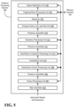
- FIG. 5 illustrates a graphics processing pipeline 500, according to an embodiment.
- a graphics processor can implement the illustrated graphics processing pipeline 500.
- the graphics processor can be included within the parallel processing subsystems as described herein, such as the parallel processor 200 of FIG. 2 , which, in one embodiment, is a variant of the parallel processor(s) 112 of FIG. 1 .
- the various parallel processing systems can implement the graphics processing pipeline 500 via one or more instances of the parallel processing unit (e.g., parallel processing unit 202 of FIG. 2 ) as described herein.
- a shader unit e.g., graphics multiprocessor 234 of FIG.
- a vertex processing unit 504 may be configured to perform the functions of one or more of a vertex processing unit 504, a tessellation control processing unit 508, a tessellation evaluation processing unit 512, a geometry processing unit 516, and a fragment/pixel processing unit 524.
- the functions of data assembler 502, primitive assemblers 506, 514, 518, tessellation unit 510, rasterizer 522, and raster operations unit 526 may also be performed by other processing engines within a processing cluster (e.g., processing cluster 214 of FIG. 3 ) and a corresponding partition unit (e.g., partition unit 220A-220N of FIG. 2 ).
- the graphics processing pipeline 500 may also be implemented using dedicated processing units for one or more functions.
- one or more portions of the graphics processing pipeline 500 can be performed by parallel processing logic within a general purpose processor (e.g., CPU). In one embodiment, one or more portions of the graphics processing pipeline 500 can access on-chip memory (e.g., parallel processor memory 222 as in FIG. 2 ) via a memory interface 528, which may be an instance of the memory interface 218 of FIG. 2 .
- a general purpose processor e.g., CPU
- on-chip memory e.g., parallel processor memory 222 as in FIG. 2
- memory interface 528 may be an instance of the memory interface 218 of FIG. 2 .
- the data assembler 502 is a processing unit that collects vertex data for surfaces and primitives. The data assembler 502 then outputs the vertex data, including the vertex attributes, to the vertex processing unit 504.
- the vertex processing unit 504 is a programmable execution unit that executes vertex shader programs, lighting and transforming vertex data as specified by the vertex shader programs.
- the vertex processing unit 504 reads data that is stored in cache, local or system memory for use in processing the vertex data and may be programmed to transform the vertex data from an object-based coordinate representation to a world space coordinate space or a normalized device coordinate space.
- the tessellation control processing unit 508 treats the input vertices as control points for a geometric patch.
- the control points are transformed from an input representation from the patch (e.g., the patch's bases) to a representation that is suitable for use in surface evaluation by the tessellation evaluation processing unit 512.
- the tessellation control processing unit 508 can also compute tessellation factors for edges of geometric patches.
- a tessellation factor applies to a single edge and quantifies a view-dependent level of detail associated with the edge.
- a tessellation unit 510 is configured to receive the tessellation factors for edges of a patch and to tessellate the patch into multiple geometric primitives such as line, triangle, or quadrilateral primitives, which are transmitted to a tessellation evaluation processing unit 512.
- the tessellation evaluation processing unit 512 operates on parameterized coordinates of the subdivided patch to generate a surface representation and vertex attributes for each vertex associated with the geometric primitives.
- a second instance of a primitive assembler 514 receives vertex attributes from the tessellation evaluation processing unit 512, reading stored vertex attributes as needed, and constructs graphics primitives for processing by the geometry processing unit 516.
- the geometry processing unit 516 is a programmable execution unit that executes geometry shader programs to transform graphics primitives received from primitive assembler 514 as specified by the geometry shader programs.
- the geometry processing unit 516 is programmed to subdivide the graphics primitives into one or more new graphics primitives and calculate parameters used to rasterize the new graphics primitives.
- the geometry processing unit 516 can add or delete elements in the geometry stream.
- the geometry processing unit 516 outputs the parameters and vertices specifying new graphics primitives to primitive assembler 518.
- the primitive assembler 518 receives the parameters and vertices from the geometry processing unit 516 and constructs graphics primitives for processing by a viewport scale, cull, and clip unit 520.
- the geometry processing unit 516 reads data that is stored in parallel processor memory or system memory for use in processing the geometry data.
- the viewport scale, cull, and clip unit 520 performs clipping, culling, and viewport scaling and outputs processed graphics primitives to a rasterizer 522.
- the rasterizer 522 can perform depth culling and other depth-based optimizations.
- the rasterizer 522 also performs scan conversion on the new graphics primitives to generate fragments and output those fragments and associated coverage data to the fragment/pixel processing unit 524.
- the fragment/pixel processing unit 524 is a programmable execution unit that is configured to execute fragment shader programs or pixel shader programs.
- the fragment/pixel processing unit 524 transforming fragments or pixels received from rasterizer 522, as specified by the fragment or pixel shader programs.
- the fragment/pixel processing unit 524 may be programmed to perform operations included but not limited to texture mapping, shading, blending, texture correction and perspective correction to produce shaded fragments or pixels that are output to a raster operations unit 526.
- the fragment/pixel processing unit 524 can read data that is stored in either the parallel processor memory or the system memory for use when processing the fragment data.
- Fragment or pixel shader programs may be configured to shade at sample, pixel, tile, or other granularities depending on the sampling rate configured for the processing units.
- the raster operations unit 526 is a processing unit that performs raster operations including, but not limited to stencil, z test, blending, and the like, and outputs pixel data as processed graphics data to be stored in graphics memory (e.g., parallel processor memory 222 as in FIG. 2 , and/or system memory 104 as in FIG 1 , to be displayed on the one or more display device(s) 110 or for further processing by one of the one or more processor(s) 102 or parallel processor(s) 112.
- the raster operations unit 526 is configured to compress z or color data that is written to memory and decompress z or color data that is read from memory.
- an embodiment of an electronic processing system 600 may include an application processor 601, persistent storage media 602 communicatively coupled to the application processor 601, a graphics subsystem 603 communicatively coupled to the application processor 601, and a facial expression graphics adjuster 604 communicatively coupled to the graphics subsystem 603 to adjust a parameter of the graphics subsystem 603 based on a detected facial expression of a user.
- the system 600 may further include one or more of a sense engine 605, a focus engine 606, and/or a motion engine 607, each of which may be communicatively coupled to the graphics subsystem 603.
- the sense engine 605 may include a light detector 608 to detect an amount of ambient light. Some embodiments may advantageously provide display adjustment based on ambient lighting conditions.
- the graphics subsystem may be configured to change a screen parameter based on the detected amount of ambient light. For example, the display brightness may be adjusted based on output of one or more light sensors which detect ambient light conditions. In some environments, the display quality may be adjusted depending on ambient light conditions. For example, in a dark environment a dimmer display may be easier to look at while in a bright environment the user may prefer increased display brightness (consumes more power).
- the system 600 may use the light detector 608 to regulate the display brightness, contrast, etc. based on the sensed light in the environment. Information from the light detector 608 may be combined with other embodiments described herein (e.g. facial expression detection) for an improved user experience.
- the facial expression graphics adjuster 604 may include a facial expression detector to detect the facial expression of the user, and a parameter adjuster communicatively coupled to the facial expression detector to adjust the parameter of the graphics subsystem based on the detected facial expression of the user (e.g. as described in more detail below).
- the detected facial expression may include one or more of a squinting, blinking, winking, and facial muscle tension of the user.
- the parameter of the graphics subsystem 603 may include one or more of a scene zoom, a scene position, and a screen parameter.
- Embodiments of each of the above application processor 601, persistent storage media 602, graphics subsystem 603, facial expression graphics adjuster 604, sense engine 605, focus engine 606, motion engine 607, light detector 608, and other system components may be implemented in hardware, software, or any suitable combination thereof.
- hardware implementations may include configurable logic such as, for example, programmable logic arrays (PLAs), FPGAs, complex programmable logic devices (CPLDs), or in fixed-functionality logic hardware using circuit technology such as, for example, ASIC, complementary metal oxide semiconductor (CMOS) or transistor-transistor logic (TTL) technology, or any combination thereof.
- PLAs programmable logic arrays
- CPLDs complex programmable logic devices
- TTL transistor-transistor logic
- a sense engine 612 may get information from sensors, content, services, and/or other sources to provide sensed information.
- the sensed information may include, for example, image information, audio information, motion information, depth information, temperature information, biometric information, GPU information, etc.
- some embodiments may use sensed information to adjust performance parameters of the graphics system.
- a sense engine may include a sensor hub communicatively coupled to two dimensional (2D) cameras, three dimensional (3D) cameras, depth cameras, gyroscopes, accelerometers, inertial measurement units (IMUs), location services, microphones, proximity sensors, thermometers, biometric sensors, etc., and/or a combination of multiple sources which provide information to the focus and/or motion engines.
- the sensor hub may be distributed across multiple devices.
- the information from the sensor hub may include or be combined with input data from the user's devices (e.g. touch data).
- the user's device(s) may include one or more 2D, 3D, and/or depth cameras.
- the user's device(s) may also include gyroscopes, accelerometers, IMUs, location services, thermometers, biometric sensors, etc.
- the user may carry a smartphone (e.g. in the user's pocket) and/or may wear a wearable device (e.g. such as a smart watch, an activity monitor, and/or a fitness tracker).
- the user's device(s) may also include a microphone which may be utilized to detect if the user is speaking, on the phone, speaking to another nearby person, etc.
- a focus engine 614 may get information from the sense engine and/or motion engine and other sources to provide focus information.
- the focus information may include, for example, a focal point, a focus area, an eye position, eye motion, pupil size, pupil dilation, depth of focus (DOF), a content focal point, a content focus object, a content focus area, etc.
- the focus information may also include prior focus information, determined future focus information, and/or predicted focus information (e.g.
- some embodiments may use focus information to adjust performance parameters of the graphics system based on 1) where the user is assumed to be looking, 2) where the user is determined to be looking, 3) where an application wants the user to look, and/or 4) where the user is predicted to be looking in the future.
- Some focus cues may be stronger in the focal region of where the user is looking. If the user is looking straight ahead they may see things in sharp focus. With scenes or objects towards the periphery, the user may notice motion but not details in sharp focus.
- Some embodiments may include an eye tracker or get eye information from an eye tracker to track the user's eyes.
- the eye information may include eye position, eye motion, pupil size/dilation, depth of focus, etc.
- An eye tracker may capture an image of the user's eye, including the pupil.
- the user's focal point and/or DOF may be determined, inferred, and/or estimated based on the eye position and pupil dilation.
- the user may go through a calibration process which may help the eye tracker provide more accurate focus, DOF, and/or other information.
- the focus information may include content-based focus information.
- content-based focus information For example, in a 3D, VR, and/or augmented reality (AR) environment, depth and/or distance information may be provided from an application (e.g. where user is in the virtual environment, where objects are, and/or how far the objects are from the user, etc.).
- Content-based focus information may also include a point, object, or area in the content where the application wants the user to focus, such as something more interesting happening for which the application wants the user's attention.
- the application may also be able to provide future content focus information because the application may know motion information for the content and/or what objects/areas in a next frame or scene may be of more interest to the user (e.g. an object about to enter the scene from an edge of the screen).
- a motion engine 616 may get information from the sense engine and/or focus engine and other sources to provide motion information.
- the motion information may include, for example, head position, head velocity, head acceleration, head motion direction, eye velocity, eye acceleration, eye motion direction, object position, object velocity, object acceleration, object motion direction, etc.
- the motion information may also include prior motion information, determined future motion information, and/or predicted motion information (e.g. a predicted head velocity, a predicted head acceleration, a predicted head position, a predicted head motion direction, a predicted eye velocity, a predicted eye acceleration, a predicted eye motion direction, determined future content position, determined future content object velocity, determined future content object acceleration, predicted object position, predicted object velocity, predicted object acceleration, etc.).
- some embodiments may use motion information to adjust performance parameters of the graphics system based on 1) the user moving their head, 2) the user moving their eyes, 3) the user moving their body, 4) where an application wants the user to turn their head, eyes, and/or body, and/or 4) where the user is predicted to turn their head, eyes, and/or body in the future.
- Some motion information may be determined readily from the sensed information. For example, head position, velocity, acceleration, motion direction, etc. may be determined from an accelerometer. Eye motion information may be determined by tracking eye position information over time (e.g. if the eye tracker provides only eye position information).
- Some motion information may be content-based.
- the application may know how quickly and where the objects are moving.
- the application may provide the information to the motion engine (e.g. through an API call).
- Future content-based object motion information for a next frame/scene may also be fed into the motion engine for decision making.
- Some content-based motion information may be determined by image processing or machine vision processing the content.
- Some embodiments of a machine vision system may analyze and/or perform feature/object recognition on images captured by a camera. For example, machine vision and/or image processing may identify and/or recognize objects in a scene (e.g. that an edge belongs to a front of a chair).
- the machine vision system may also be configured to perform facial recognition, gaze tracking, facial expression recognition, and/or gesture recognition including body-level gestures, arm/leg-level gestures, hand-level gestures, and/or finger-level gestures.
- the machine vision system may be configured to classify an action of the user.
- a suitably configured machine vision system may be able to determine if the user is present at a computer, typing at a keyboard, using the mouse, using the trackpad, using the touchscreen, using a HMD, using a VR system, sitting, standing, and/or otherwise taking some other action or activity.
- the motion engine may get camera data related to a real object in a scene and may use that information to identify motion and orientation of the real object.
- the motion engine may get latency information from the graphics processor.
- the motion engine may then predict the next frame orientation of that real object.
- the amount of latency may be based on one or more of time to render a scene, number of virtual objects in the scene, and a complexity of the scene, etc.
- a sense engine may include one or more cameras to capture a real scene.
- the one or more cameras may include one or more 2D cameras, 3D cameras, depth cameras, high speed cameras, or other image capture devices.
- the real scene may include an object moving in the scene.
- the cameras may be coupled to an image processor to process data from the cameras to identify objects in the scene (e.g. including the moving object) and to identify motion of the object (e.g. including orientation information).
- the motion engine may determine predicted motion information based on tracking the motion of the object and predict a future position of the object based on a measured or estimated latency (e.g. from the time of capture to the time of rendering).
- various motion tracking and/or motion prediction techniques may be augmented with optical flow and other real motion estimation techniques to determine the next location of the real objects.
- some embodiments may use extended common filtering and/or perspective processing (e.g. from autonomous driving applications) to predict motion of objects.
- the focus engine may use motion information to provide a predicted future focus area and the motion engine may use focus information to predict a future motion.
- Eye motion information may come directly from the sense engine, may be determined/predicted by the focus engine, and/or may be determined/predicted by the motion engine.
- an embodiment of a graphics apparatus 700 may include a facial expression detector 721 to detect a facial expression of a user, and a parameter adjuster 722 communicatively coupled to the facial expression detector 721 to adjust a graphics parameter based on the detected facial expression of the user.
- the detected facial expression may include one or more of a squinting, blinking, winking, and facial muscle tension of the user.
- the graphics parameter may include one or more of a frame resolution, a screen contrast, a screen brightness, and a shading rate.
- the parameter adjuster 722 may be configured to adjust the graphics parameter in an area of focus based on the detected facial expression of the user to improve the perception of the user in the area of focus.
- the facial expression detector 721 may include a camera that continuously captures images of the user's face. The images may be machine-analyzed (e.g. using a machine learning system, either locally or in the cloud) to determine the user's facial expression.
- the facial expression detector 721 may be configured to detect an amount of the facial expression of the user. For example, an amount of the adjustment of the graphics parameter may be based on the amount of the detected facial expression of the user.
- the graphics parameter may include a zoom of a graphics scene.
- the facial expression detector 721 may be configured to detect an amount of a squinting of the user based on a detected distance between eyelids of the user, and the parameter adjuster 722 may be configured to adjust an amount of the zoom of the graphics scene based on the amount of the detected squinting of the user.
- the parameter adjuster 722 may also be configured to adjust the graphics parameter based on at least one other detected input.
- the at least one other detected input may include one or more of a pulse rate, a heart rate, and a gesture of the user.
- the facial expression detector 721 may additionally, or alternatively, be configured to detect a number of blinks of the user.
- the parameter adjuster 722 may be configured to adjust the graphics parameter based on the detected number of blinks of the user to improve the perception of the user.
- the facial expression detector 721 may also be configured to detect a visual impairment of the user.
- the detected visual impairment may include one or more of the presence of eye glasses and the presence of an eye patch.
- the apparatus 700 may further include a light detector 723 communicatively coupled to the parameter adjuster 722 to detect an amount of ambient light.
- the parameter adjuster 722 may be configured to adjust the graphics parameter based on the amount of detected ambient light.
- the facial expression detector 721 may additionally, or alternatively, be configured to predictively adjust the graphics parameter based on a comparison of the detected facial expression and previously detected facial expressions. For example, if the user blinks every 3 seconds, and the system detects the user starting to blink three seconds after the last one, then the system may predict that it is a normal blink and may suspend rendering while the full blink is occurring.
- the predictive adjustment may reduce some latency associated with the facial detection system.
- Embodiments of each of the above facial expression detector 721, parameter adjuster 722, light detector 723, and other components of the apparatus 700 may be implemented in hardware, software, or any combination thereof.
- portions or all of the apparatus 700 may be implemented as part of the parallel processor 200, further configured with a facial expression detector and parameter adjuster as described herein.
- the apparatus 700 may also be adapted to work with a stereo head mounted system such as, for example, the system described in connection with FIGs. 11-15 below.
- hardware implementations may include configurable logic such as, for example, PLAs, FPGAs, CPLDs, or in fixed-functionality logic hardware using circuit technology such as, for example, ASIC, CMOS, or TTL technology, or any combination thereof.
- these components may be implemented in one or more modules as a set of logic instructions stored in a machine- or computer-readable storage medium such as RAM, ROM, PROM, firmware, flash memory, etc., to be executed by a processor or computing device.
- computer program code to carry out the operations of the components may be written in any combination of one or more operating system applicable/appropriate programming languages, including an object-oriented programming language such as PYTHON, PERL, JAVA, SMALLTALK, C++, C# or the like and conventional procedural programming languages, such as the "C" programming language or similar programming languages.
- an embodiment of a method 800 of adjusting graphics may include detecting a facial expression of a user at block 831, and adjusting a graphics parameter based on the detected facial expression of the user at block 832.
- the detected facial expression may include one or more of a squinting, blinking, winking, and facial muscle tension of the user at block 833.
- the graphics parameter may include one or more of a frame resolution, a screen contrast, a screen brightness, and a shading rate at block 834.
- the method 800 may include adjusting the graphics parameter in an area of focus based on the detected facial expression of the user to improve the perception of the user in the area of focus at block 835.
- the method 800 may further include detecting an amount of the facial expression of the user at block 836.
- an amount of the adjustment of the graphics parameter is based on the amount of the detected facial expression of the user at block 837.
- the graphics parameter may include a zoom of a graphics scene at block 838.
- the method 800 may include detecting an amount of a squinting of the user based on a detected distance between eyelids of the user at block 839, and adjusting an amount of the zoom of the graphics scene based on the amount of the detected squinting of the user at block 840.
- Some embodiments may further include adjusting the graphics parameter based on at least one other detected input at block 841.
- the at least one other detected input may include one or more of a pulse rate, a heart rate, and a gesture of the user at block 842.
- the method 800 may further include detecting a number of blinks of the user at block 843, and adjusting the graphics parameter based on the detected number of blinks of the user to improve the perception of the user at block 844. Some embodiments may further include detecting a visual impairment of the user at block 845. For example, the detected visual impairment may include one or more of the presence of eye glasses and the presence of an eye patch at block 846. Some embodiments may also include detecting an amount of ambient light at block 847, and adjusting the graphics parameter based on the amount of detected ambient light at block 848. For example, the method 800 may further include predictively adjusting the graphics parameter based on a comparison of the detected facial expression and previously detected facial expressions at block 849.
- Embodiments of the method 800 may be implemented in a system, apparatus, GPU, PPU, or a graphics processor pipeline apparatus such as, for example, those described herein. More particularly, hardware implementations of the method 800 may include configurable logic such as, for example, PLAs, FPGAs, CPLDs, or in fixed-functionality logic hardware using circuit technology such as, for example, ASIC, CMOS, or TTL technology, or any combination thereof. Alternatively, or additionally, the method 800 may be implemented in one or more modules as a set of logic instructions stored in a machine- or computer-readable storage medium such as RAM, ROM, PROM, firmware, flash memory, etc., to be executed by a processor or computing device.
- a machine- or computer-readable storage medium such as RAM, ROM, PROM, firmware, flash memory, etc.
- computer program code to carry out the operations of the components may be written in any combination of one or more operating system applicable/appropriate programming languages, including an object-oriented programming language such as PYTHON, PERL, JAVA, SMALLTALK, C++, C# or the like and conventional procedural programming languages, such as the "C" programming language or similar programming languages.
- object-oriented programming language such as PYTHON, PERL, JAVA, SMALLTALK, C++, C# or the like
- conventional procedural programming languages such as the "C" programming language or similar programming languages.
- the method 800 may be implemented on a computer readable medium as described in connection with Examples 36 to 51 below.
- embodiments or portions of the method 800 may be implemented in applications (e.g. through an API) or driver software. Other embodiments or portions of the method 800 may be implemented in specialized code (e.g. shaders) to be executed on a GPU. Other embodiments or portions of the method 800 may be implemented in fixed function logic or specialized hardware (e.g. in the GPU).
- a graphics system 900 may include a display 902 and a camera 904 to capture eye information for a user 906.
- the camera 904 may capture an image of one or both eyes of the user 906.
- the image may include a portion of the face of the user 906 including the eyelids and/or area of the face near the eyes of the user 906.
- the system 900 may process the image from the camera 904 to detect if the user 906 is squinting, blinking, and/or winking.
- the system 900 may additionally, or alternatively, process the image from the camera to detect facial muscle tension (e.g. if the skin is wrinkled or creased near the eyes).
- the system 900 may determine that the user blinked. If both eyelids partially close, the system 900 may determine that the user is squinting. If one closes while the other eye remains open, the system 900 may determine that the user is winking. For both squinting and winking, the system 900 may analyze facial muscle tension information together with the eyelid information to determine that the user is squinting or winking.
- the user may be asked to focus on an area and squint, blink, and/or wink.
- the calibration or other settings e.g. type or amount of adjustment associated with a facial expression may be user adjustable (e.g. setting/slider bar for more adjustment/less adjustment) or included as part of various power/performance settings.
- the system may combine the detected squinting with another input (e.g. pulse, heart rate, gesture recognition such as pointing) to trigger an associated action.
- another input e.g. pulse, heart rate, gesture recognition such as pointing
- some other facial recognition e.g. such as head squishing or some other detected facial muscle tension
- an associated action e.g. such as zoom or pan.
- a wink with the right eye may cause the application to pan/scroll right while a wink with the left eye may cause the application to pan/scroll left. Wrinkling the nose may cause the application to pan/scroll up while dropping the jaw may cause the application to pan/scroll down.
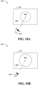
- a foveated rendering system 1000 may provide a relatively higher resolution region 1002 and a relatively lower resolution region 1004 of a display 1006 based on an area of focus of a user 1008.
- Some embodiments may advantageously provide facial expression tracking for foveated rendering. For example, some embodiments may detect facial expressions such as squinting to control an area of focus. The size of the relatively higher resolution region 1002 may be adjusted based on the detected squinting of the user 1008 (e.g. see FIG. 10B ).
- some embodiments may alter the foveated rendering for the relatively higher resolution region 1002 to change attributes such as shading rate, contrast, etc. to make it easier for the user 1008 to perceive the scene.
- FIG. 12 shows the HMD system in greater detail.
- the frame 1102 includes a power unit 1200 (e.g., battery power, adapter) to provide power to the HMD system.
- the illustrated frame 1102 also includes a motion tracking module 1220 (e.g., accelerometers, gyroscopes), wherein the motion tracking module 1220 provides motion tracking data, orientation data and/or position data to a processor system 1204.
- the processor system 1204 may include a network adapter 1224 that is coupled to an I/O bridge 1206.
- the I/O bridge 1206 may enable communications between the network adapter 1224 and various components such as, for example, audio input modules 1210, audio output modules 1208, a display device 1207, input cameras 1202, and so forth.
- the audio input modules 1210 include a right-audio input 1218 and a left-audio input 1216, which detect sound that may be processed in order to recognize voice commands of the user as well as nearby individuals.
- the voice commands recognized in the captured audio signals may augment gesture recognition during modality switching and other applications.
- the captured audio signals may provide 3D information that is used to enhance the immersive experience.
- the audio output modules 1208 may include a right-audio output 1214 and a left-audio output 1212.
- the audio output modules 1208 may deliver sound to the ears of the user and/or other nearby individuals.
- the audio output modules 1208, which may be in the form of earbuds, on-ear speakers, over the ear speakers, loudspeakers, etc., or any combination thereof, may deliver stereo and/or 3D audio content to the user (e.g., spatial localization).
- the illustrated frame 1102 also includes a wireless module 1222, which may facilitate communications between the HMD system and various other systems (e.g., computers, wearable devices, game consoles). In one example, the wireless module 1222 communicates with the processor system 1204 via the network adapter 1224.
- the illustrated display device 1207 includes the left-eye display 1104 and the right-eye display 1106, wherein the visual content presented on the displays 1104, 1106 may be obtained from the processor system 1204 via the I/O bridge 1206.
- the input cameras 1202 may include the left look-side camera 1116 the right look-side camera 1118, the left look-down camera 1108, the left look-front camera 1112, the right look-front camera 1114 and the right look-down camera 1110, already discussed.
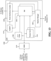
- the illustrated GPC 1300 may be incorporated into a processing system such as, for example, the processor system 1204 ( FIG. 12 ), already discussed.
- the GPC 1300 may include a pipeline manager 1302 that communicates with a scheduler.
- the pipeline manager 1302 receives tasks from the scheduler and distributes the tasks to one or more streaming multi-processors (SM's) 1304.
- SM's streaming multi-processors
- Each SM 1304 may be configured to process thread groups, wherein a thread group may be considered a plurality of related threads that execute the same or similar operations on different input data. Thus, each thread in the thread group may be assigned to a particular SM 1304.
- the number of threads may be greater than the number of execution units in the SM 1304.
- the threads of a thread group may operate in parallel.
- the pipeline manager 1302 may also specify processed data destinations to a work distribution crossbar 1308, which communicates with a memory crossbar.
- each SM 1304 transmits a processed task to the work distribution crossbar 1308, the processed task may be provided to another GPC 1300 for further processing.
- the output of the SM 1304 may also be sent to a pre-raster operations (preROP) unit 1314, which in turn directs data to one or more raster operations units, or performs other operations (e.g., performing address translations, organizing picture color data, blending color, and so forth).
- the SM 1304 may include an internal level one (L1) cache (not shown) to which the SM 1304 may store data.
- the SM 1304 may also have access to a level two (L2) cache (not shown) via a memory management unit (MMU) 1310 and a level one point five (L1.5) cache 1306.
- MMU memory management unit
- the MMU 1310 may map virtual addresses to physical addresses.
- the MMU 1310 may include page table entries (PTE's) that are used to map virtual addresses to physical addresses of a tile, memory page and/or cache line index.
- PTE's page table entries
- the illustrated GPC 1300 also includes a texture unit 1312.
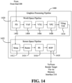
- a graphics pipeline 1400 is shown.
- a world space pipeline 1420 includes a primitive distributor (PD) 1402.
- the PD 1402 may collect vertex data associated with high-order services, graphics primitives, triangles, etc., and transmit the vertex data to a vertex attribute fetch unit (VAF) 1404.
- VAF vertex attribute fetch unit
- the VAF 1404 may retrieve vertex attributes associated with each of the incoming vertices from shared memory and store the vertex data, along with the associated vertex attributes, into shared memory.
- the illustrated world space pipeline 1420 also includes a vertex, tessellation, geometry processing unit (VTG) 1406.
- the VTG 1406 may include, for example, a vertex processing unit, a tessellation initialization processing unit, a task distributor, a task generation unit, a topology generation unit, a geometry processing unit, a tessellation processing unit, etc., or any combination thereof.
- the VTG 1406 is a programmable execution unit that is configured to execute geometry programs, tessellation programs, and vertex shader programs.
- the programs executed by the VTG 1406 may process the vertex data and vertex attributes received from the VAF 1404.
- the programs executed by the VTG 1406 may produce graphics primitives, color values, surface normal factors and transparency values at each vertex for the graphics primitives for further processing within the graphics processing pipeline 1400.
- the vertex processing unit of the VTG 1406 may be a programmable execution unit that executes vertex shader programs, lighting and transforming vertex data as specified by the vertex shader programs.
- the vertex processing unit might be programmed to transform the vertex data from an object-based coordinate representation (e.g. object space) to an alternatively based coordinate system such as world space or normalize device coordinates (NDC) space.
- the vertex processing unit may read vertex data and vertex attributes that are stored in shared memory by the VAF 1404 and process the vertex data and vertex attributes. In one example, the vertex processing unit stores processed vertices in shared memory.
- the tessellation initialization processing unit may execute tessellation initialization shader programs.
- the tessellation initialization processing unit processes vertices produced by the vertex processing unit and generates graphics primitives sometimes referred to as "patches".
- the tessellation initialization processing unit may also generate various patch attributes, wherein the patch data and the patch attributes are stored to shared memory.
- the task generation unit of the VTG 1406 may retrieve data and attributes for vertices and patches from shared memory. In one example, the task generation unit generates tasks for processing the vertices and patches for processing by the later stages in the graphics processing pipeline 1400.
- the tasks produced by the task generation unit may be redistributed by the task distributor of the VTG 1406.
- the tasks produced by the various instances of the vertex shader program and the tessellation initialization program may vary significantly between one graphics processing pipeline 1400 and another. Accordingly, the task distributor may redistribute these tasks such that each graphics processing pipeline 1400 has approximately the same workload during later pipeline stages.
- the VTG 1406 may also include a topology generation unit.
- the topology generation unit retrieves tasks distributed by the task distributor, indexes the vertices, including vertices associated with patches, and computes coordinates (UV) for tessellation vertices and the indices that connect the tessellation vertices to form graphics primitives.
- the indexed vertices may be stored by the topology generation unit in shared memory.
- the tessellation processing unit of the VTG 1406 may be configured to execute tessellation shader programs (e.g., domain shaders, tessellation evaluation shaders).
- the tessellation processing unit may read input data from shared memory and write output data to shared memory.
- the output data may be passed from the shared memory to the geometry processing unit (e.g., the next shader stage) as input data.
- the geometry processing unit of the VTG 1406 may execute geometry shader programs to transform graphics primitives (e.g., triangles, line segments, points, etc.).
- graphics primitives e.g., triangles, line segments, points, etc.
- vertices are grouped to construct graphics primitives, wherein the geometry processing unit subdivides the graphics primitives into one or more new graphics primitives.
- the geometry processing unit may also calculate parameters such as, for example, plain equation coefficients, that may be used to rasterize the new graphics primitives.
- the setup unit 1412 receives vertex data from the VPC 1408 via the tiling unit 1410 and calculates parameters associated with the graphics primitives.
- the parameters may include, for example, edge equations, partial plane equations, and depth plain equations.
- the screen space pipeline 1422 may also include a rasterizer 1414 coupled to the setup unit 1412.
- the rasterizer may scan convert the new graphics primitives and transmit fragments and coverage data to a pixel shading unit (PS) 1416.
- PS pixel shading unit
- the rasterizer 1414 may also perform Z culling and other Z-based optimizations.
- the illustrated screen space pipeline 1422 also includes a raster operations unit (ROP) 1418, which may perform raster operations such as, for example, stenciling, Z-testing, blending, and so forth.
- the ROP 1418 may then transmit pixel data as processed graphics data to one or more rendered targets (e.g., graphics memory).
- the ROP 1418 may be configured to compress Z or color data that is written to memory and decompress Z or color data that is read from memory.
- the location of the ROP 1418 may vary depending on the circumstances.
- the graphics processing pipeline 1400 may perform a first set of operations (e.g., a single thread, a thread group, multiple thread groups acting in unison) in the alpha phase pipeline and a second set of operations (e.g., a single thread, a thread group, multiple thread groups acting in unison) in the beta phase pipeline.
- a first set of operations e.g., a single thread, a thread group, multiple thread groups acting in unison
- a second set of operations e.g., a single thread, a thread group, multiple thread groups acting in unison
- the vertex data and vertex attributes associated with a set of graphics objects may be divided so that each graphics processing pipeline 1400 has a similar workload through the alpha phase. Accordingly, alpha phase processing may substantially expand the amount of vertex data and vertex attributes, such that the amount of vertex data and vertex attributes produced by the task generation unit is significantly larger than the amount of vertex data and vertex attributes processed by the PD 1402 and the VAF 1404. Moreover, the task generation units associated with different graphics processing pipelines 1400 may produce vertex data and vertex attributes having different levels of quality, even when beginning the alpha phase with the same quantity of attributes. In such cases, the task distributor may redistribute the attributes produced by the alpha phase pipeline so that each graphics processing pipeline 1400 has approximately the same workload at the beginning of the beta phase pipeline.
- the illustrated SM 1500 also includes M double precision units (DPU's) 1510, N special function units (SFU's) 1512 and P load/store units (LSU's) 1514.
- DPU's double precision units
- SFU's special function units
- LSU's P load/store units
- Each DPU 1510 may implement double-precision floating point arithmetic and each SFU 1512 may perform special functions such as, for example, rectangle copying pixel blending, etc.
- each LSU 1514 may conduct load and store operations between a shared memory 1518 and the register file 1506.
- the load and store operations are conducted through J texture unit/L1 caches 1520 and an interconnected network 1516.
- the J texture unit/L1 caches 1520 are also coupled to a crossbar (not shown).
- Memory device 1620 can be a dynamic random access memory (DRAM) device, a static random access memory (SRAM) device, flash memory device, phase-change memory device, or some other memory device having suitable performance to serve as process memory.
- the memory device 1620 can operate as system memory for the system 1600, to store data 1622 and instructions 1621 for use when the one or more processors 1602 executes an application or process.
- Memory controller hub 1616 also couples with an optional external graphics processor 1612, which may communicate with the one or more graphics processors 1608 in processors 1602 to perform graphics and media operations.
- ICH 1630 enables peripherals to connect to memory device 1620 and processor 1602 via a high-speed I/O bus.
- the I/O peripherals include, but are not limited to, an audio controller 1646, a firmware interface 1628, a wireless transceiver 1626 (e.g., Wi-Fi, Bluetooth), a data storage device 1624 (e.g., hard disk drive, flash memory, etc.), and a legacy I/O controller 1640 for coupling legacy (e.g., Personal System 2 (PS/2)) devices to the system.
- PS/2 Personal System 2
- One or more Universal Serial Bus (USB) controllers 1642 connect input devices, such as keyboard and mouse 1644 combinations.
- a network controller 1634 may also couple to ICH 1630.
- a high-performance network controller couples to processor bus 1610.
- processor bus 1610 couples to processor bus 1610.
- the I/O controller hub 1630 may be integrated within the one or more processor 1602, or the memory controller hub 1616 and I/O controller hub 1630 may be integrated into a discreet external graphics processor, such as the external graphics processor 1612.
- FIG. 17 is a block diagram of an embodiment of a processor 1700 having one or more processor cores 1702A-1702N, an integrated memory controller 1714, and an integrated graphics processor 1708. Those elements of FIG. 17 having the same reference numbers (or names) as the elements of any other figure herein can operate or function in any manner similar to that described elsewhere herein, but are not limited to such.
- Processor 1700 can include additional cores up to and including additional core 1702N represented by the dashed lined boxes.
- Each of processor cores 1702A-1702N includes one or more internal cache units 1704A-1704N. In some embodiments each processor core also has access to one or more shared cached units 1706.
- processor 1700 may also include a set of one or more bus controller units 1716 and a system agent core 1710.
- the one or more bus controller units 1716 manage a set of peripheral buses, such as one or more Peripheral Component Interconnect buses (e.g., PCI, PCI Express).
- System agent core 1710 provides management functionality for the various processor components.
- system agent core 1710 includes one or more integrated memory controllers 1714 to manage access to various external memory devices (not shown).
- one or more of the processor cores 1702A-1702N include support for simultaneous multi-threading.
- the system agent core 1710 includes components for coordinating and operating cores 1702A-1702N during multi-threaded processing.
- System agent core 1710 may additionally include a power control unit (PCU), which includes logic and components to regulate the power state of processor cores 1702A-1702N and graphics processor 1708.
- PCU power control unit
- processor 1700 additionally includes graphics processor 1708 to execute graphics processing operations.
- the graphics processor 1708 couples with the set of shared cache units 1706, and the system agent core 1710, including the one or more integrated memory controllers 1714.
- a display controller 1711 is coupled with the graphics processor 1708 to drive graphics processor output to one or more coupled displays.
- display controller 1711 may be a separate module coupled with the graphics processor via at least one interconnect, or may be integrated within the graphics processor 1708 or system agent core 1710.
- a ring based interconnect unit 1712 is used to couple the internal components of the processor 1700.
- an alternative interconnect unit may be used, such as a point-to-point interconnect, a switched interconnect, or other techniques, including techniques well known in the art.
- graphics processor 1708 couples with the ring interconnect 1712 via an I/O link 1713.
- the exemplary I/O link 1713 represents at least one of multiple varieties of I/O interconnects, including an on package I/O interconnect which facilitates communication between various processor components and a high-performance embedded memory module 1718, such as an eDRAM module.
- a high-performance embedded memory module 1718 such as an eDRAM module.
- each of the processor cores 1702-1702N and graphics processor 1708 use embedded memory modules 1718 as a shared Last Level Cache.
- processor cores 1702A-1702N are homogenous cores executing the same instruction set architecture.
- processor cores 1702A-1702N are heterogeneous in terms of instruction set architecture (ISA), where one or more of processor cores 1702A-N execute a first instruction set, while at least one of the other cores executes a subset of the first instruction set or a different instruction set.
- processor cores 1702A-1702N are heterogeneous in terms of microarchitecture, where one or more cores having a relatively higher power consumption couple with one or more power cores having a lower power consumption.
- processor 1700 can be implemented on one or more chips or as an SoC integrated circuit having the illustrated components, in addition to other components.
- FIG. 18 is a block diagram of a graphics processor 1800, which may be a discrete graphics processing unit, or may be a graphics processor integrated with a plurality of processing cores.
- the graphics processor communicates via a memory mapped I/O interface to registers on the graphics processor and with commands placed into the processor memory.
- graphics processor 1800 includes a memory interface 1814 to access memory.
- Memory interface 1814 can be an interface to local memory, one or more internal caches, one or more shared external caches, and/or to system memory.
- graphics processor 1800 also includes a display controller 1802 to drive display output data to a display device 1820.
- Display controller 1802 includes hardware for one or more overlay planes for the display and composition of multiple layers of video or user interface elements.
- graphics processor 1800 includes a video codec engine 1806 to encode, decode, or transcode media to, from, or between one or more media encoding formats, including, but not limited to Moving Picture Experts Group (MPEG) formats such as MPEG-2, Advanced Video Coding (AVC) formats such as H.264/MPEG-4 AVC, as well as the Society of Motion Picture & Television Engineers (SMPTE) 421M/VC-1, and Joint Photographic Experts Group (JPEG) formats such as JPEG, and Motion JPEG (MJPEG) formats.
- MPEG Moving Picture Experts Group
- AVC Advanced Video Coding
- SMPTE Society of Motion Picture & Television Engineers
- JPEG Joint Photographic Experts Group
- JPEG Joint Photographic Experts Group
- graphics processor 1800 includes a block image transfer (BLIT) engine 1804 to perform two-dimensional (2D) rasterizer operations including, for example, bit-boundary block transfers.
- 2D graphics operations are performed using one or more components of graphics processing engine (GPE) 1810.
- graphics processing engine 1810 is a compute engine for performing graphics operations, including three-dimensional (3D) graphics operations and media operations.
- GPE 1810 includes a 3D pipeline 1812 for performing 3D operations, such as rendering three-dimensional images and scenes using processing functions that act upon 3D primitive shapes (e.g., rectangle, triangle, etc.).
- the 3D pipeline 1812 includes programmable and fixed function elements that perform various tasks within the element and/or spawn execution threads to a 3D/Media sub-system 1815. While 3D pipeline 1812 can be used to perform media operations, an embodiment of GPE 1810 also includes a media pipeline 1816 that is specifically used to perform media operations, such as video post-processing and image enhancement.
- media pipeline 1816 includes fixed function or programmable logic units to perform one or more specialized media operations, such as video decode acceleration, video de-interlacing, and video encode acceleration in place of, or on behalf of video codec engine 1806.
- media pipeline 1816 additionally includes a thread spawning unit to spawn threads for execution on 3D/Media sub-system 1815. The spawned threads perform computations for the media operations on one or more graphics execution units included in 3D/Media sub-system 1815.
- 3D/Media subsystem 1815 includes logic for executing threads spawned by 3D pipeline 1812 and media pipeline 1816.
- the pipelines send thread execution requests to 3D/Media subsystem 1815, which includes thread dispatch logic for arbitrating and dispatching the various requests to available thread execution resources.
- the execution resources include an array of graphics execution units to process the 3D and media threads.
- 3D/Media subsystem 1815 includes one or more internal caches for thread instructions and data.
- the subsystem also includes shared memory, including registers and addressable memory, to share data between threads and to store output data.
- FIG. 19 is a block diagram of a graphics processing engine 1910 of a graphics processor in accordance with some embodiments.
- the GPE 1910 is a version of the GPE 1810 shown in FIG. 18 .
- Elements of FIG. 19 having the same reference numbers (or names) as the elements of any other figure herein can operate or function in any manner similar to that described elsewhere herein, but are not limited to such.
- GPE 1910 couples with a command streamer 1903, which provides a command stream to the GPE 3D and media pipelines 1912, 1916.
- command streamer 1903 is coupled to memory, which can be system memory, or one or more of internal cache memory and shared cache memory.
- command streamer 1903 receives commands from the memory and sends the commands to 3D pipeline 1912 and/or media pipeline 1916.
- the commands are directives fetched from a ring buffer, which stores commands for the 3D and media pipelines 1912, 1916.
- the ring buffer can additionally include batch command buffers storing batches of multiple commands.
- execution unit array 1914 is scalable, such that the array includes a variable number of execution units based on the target power and performance level of GPE 1910.
- a sampling engine 1930 couples with memory (e.g., cache memory or system memory) and execution unit array 1914.
- sampling engine 1930 provides a memory access mechanism for execution unit array 1914 that allows execution array 1914 to read graphics and media data from memory.
- sampling engine 1930 includes logic to perform specialized image sampling operations for media.
- the specialized media sampling logic in sampling engine 1930 includes a de-noise/de-interlace module 1932, a motion estimation module 1934, and an image scaling and filtering module 1936.
- de-noise/de-interlace module 1932 includes logic to perform one or more of a de-noise or a de-interlace algorithm on decoded video data.
- the de-interlace logic combines alternating fields of interlaced video content into a single fame of video.
- the de-noise logic reduces or removes data noise from video and image data.
- the de-noise logic and de-interlace logic are motion adaptive and use spatial or temporal filtering based on the amount of motion detected in the video data.
- the de-noise/de-interlace module 1932 includes dedicated motion detection logic (e.g., within the motion estimation engine 1934).
- motion estimation engine 1934 provides hardware acceleration for video operations by performing video acceleration functions such as motion vector estimation and prediction on video data.
- the motion estimation engine determines motion vectors that describe the transformation of image data between successive video frames.
- a graphics processor media codec uses video motion estimation engine 1934 to perform operations on video at the macro-block level that may otherwise be too computationally intensive to perform with a general-purpose processor.
- motion estimation engine 1934 is generally available to graphics processor components to assist with video decode and processing functions that are sensitive or adaptive to the direction or magnitude of the motion within video data.
- image scaling and filtering module 1936 performs image-processing operations to enhance the visual quality of generated images and video. In some embodiments, scaling and filtering module 1936 processes image and video data during the sampling operation before providing the data to execution unit array 1914.
- the GPE 1910 includes a data port 1944, which provides an additional mechanism for graphics subsystems to access memory.
- data port 1944 facilitates memory access for operations including render target writes, constant buffer reads, scratch memory space reads/writes, and media surface accesses.
- data port 1944 includes cache memory space to cache accesses to memory.
- the cache memory can be a single data cache or separated into multiple caches for the multiple subsystems that access memory via the data port (e.g., a render buffer cache, a constant buffer cache, etc.).
- threads executing on an execution unit in execution unit array 1914 communicate with the data port by exchanging messages via a data distribution interconnect that couples each of the sub-systems of GPE 1910.
- FIG. 20 is a block diagram of another embodiment of a graphics processor 2000. Elements of FIG. 20 having the same reference numbers (or names) as the elements of any other figure herein can operate or function in any manner similar to that described elsewhere herein, but are not limited to such.
- graphics processor 2000 receives batches of commands via ring interconnect 2002. The incoming commands are interpreted by a command streamer 2003 in the pipeline front-end 2004.
- graphics processor 2000 includes scalable execution logic to perform 3D geometry processing and media processing via the graphics core(s) 2080A-2080N.
- command streamer 2003 supplies commands to geometry pipeline 2036.
- command streamer 2003 supplies the commands to a video front end 2034, which couples with a media engine 2037.
- media engine 2037 includes a Video Quality Engine (VQE) 2030 for video and image post-processing and a multi-format encode/decode (MFX) 2033 engine to provide hardware-accelerated media data encode and decode.
- geometry pipeline 2036 and media engine 2037 each generate execution threads for the thread execution resources provided by at least one graphics core 2080A.
- graphics processor 2000 includes scalable thread execution resources featuring modular cores 2080A-2080N (sometimes referred to as core slices), each having multiple sub-cores 2050A-2050N, 2060A-2060N (sometimes referred to as core sub-slices).
- graphics processor 2000 can have any number of graphics cores 2080A through 2080N.
- graphics processor 2000 includes a graphics core 2080A having at least a first sub-core 2050A and a second core sub-core 2060A.
- the graphics processor is a low power processor with a single sub-core (e.g., 2050A).
- FIG. 21 illustrates thread execution logic 2100 including an array of processing elements employed in some embodiments of a GPE. Elements of FIG. 21 having the same reference numbers (or names) as the elements of any other figure herein can operate or function in any manner similar to that described elsewhere herein, but are not limited to such.
- thread execution logic 2100 includes a pixel shader 2102, a thread dispatcher 2104, instruction cache 2106, a scalable execution unit array including a plurality of execution units 2108A-2108N, a sampler 2110, a data cache 2112, and a data port 2114.
- the included components are interconnected via an interconnect fabric that links to each of the components.
- thread execution logic 2100 includes one or more connections to memory, such as system memory or cache memory, through one or more of instruction cache 2106, data port 2114, sampler 2110, and execution unit array 2108A-2108N.
- each execution unit e.g. 2108A
- each execution unit is an individual vector processor capable of executing multiple simultaneous threads and processing multiple data elements in parallel for each thread.
- execution unit array 2108A-2108N includes any number individual execution units.
- execution unit array 2108A-2108N is primarily used to execute "shader" programs.
- the execution units in array 2108A-2108N execute an instruction set that includes native support for many standard 3D graphics shader instructions, such that shader programs from graphics libraries (e.g., Direct 3D and OpenGL) are executed with a minimal translation.
- the execution units support vertex and geometry processing (e.g., vertex programs, geometry programs, vertex shaders), pixel processing (e.g., pixel shaders, fragment shaders) and general-purpose processing (e.g., compute and media shaders).
- the execution unit instruction set includes single instruction multiple data (SIMD) instructions.
- SIMD single instruction multiple data
- the various data elements can be stored as a packed data type in a register and the execution unit will process the various elements based on the data size of the elements. For example, when operating on a 256-bit wide vector, the 256 bits of the vector are stored in a register and the execution unit operates on the vector as four separate 64-bit packed data elements (Quad-Word (QW) size data elements), eight separate 32-bit packed data elements (Double Word (DW) size data elements), sixteen separate 16-bit packed data elements (Word (W) size data elements), or thirty-two separate 8-bit data elements (byte (B) size data elements).
- QW Quad-Word
- DW Double Word
- W 16-bit packed data elements
- B thirty-two separate 8-bit data elements
- One or more internal instruction caches are included in the thread execution logic 2100 to cache thread instructions for the execution units.
- one or more data caches are included to cache thread data during thread execution.
- sampler 2110 is included to provide texture sampling for 3D operations and media sampling for media operations.
- sampler 2110 includes specialized texture or media sampling functionality to process texture or media data during the sampling process before providing the sampled data to an execution unit.
- pixel shader 2102 uses texture sampling logic in sampler 2110 to access texture data in texture maps stored in memory. Arithmetic operations on the texture data and the input geometry data compute pixel color data for each geometric fragment, or discards one or more pixels from further processing.
- the data port 2114 provides a memory access mechanism for the thread execution logic 2100 output processed data to memory for processing on a graphics processor output pipeline.
- the data port 2114 includes or couples to one or more cache memories (e.g., data cache 2112) to cache data for memory access via the data port.
- the 128-bit instruction format 2210 includes an access/address mode field 2226, which specifies an address mode and/or an access mode for the instruction.
- the access mode to define a data access alignment for the instruction.
- Some embodiments support access modes including a 16-byte aligned access mode and a 1-byte aligned access mode, where the byte alignment of the access mode determines the access alignment of the instruction operands. For example, when in a first mode, the instruction 2210 may use byte-aligned addressing for source and destination operands and when in a second mode, the instruction 2210 may use 16-byte-aligned addressing for all source and destination operands.
- a flow control instruction group 2244 (e.g., call, jump (jmp)) includes instructions in the form of 0010xxxxb (e.g., 0x20).
- a miscellaneous instruction group 2246 includes a mix of instructions, including synchronization instructions (e.g., wait, send) in the form of 0011xxxxb (e.g., 0x30).
- a parallel math instruction group 2248 includes component-wise arithmetic instructions (e.g., add, multiply (mul)) in the form of 0100xxxxb (e.g., 0x40). The parallel math group 2248 performs the arithmetic operations in parallel across data channels.
- the vector math group 2250 includes arithmetic instructions (e.g., dp4) in the form of 0101xxxxb (e.g., 0x50).
- the vector math group performs arithmetic such as dot product calculations on vector operands.
- FIG. 23 is a block diagram of another embodiment of a graphics processor 2300. Elements of FIG. 23 having the same reference numbers (or names) as the elements of any other figure herein can operate or function in any manner similar to that described elsewhere herein, but are not limited to such.
- graphics processor 2300 includes a graphics pipeline 2320, a media pipeline 2330, a display engine 2340, thread execution logic 2350, and a render output pipeline 2370.
- graphics processor 2300 is a graphics processor within a multi-core processing system that includes one or more general purpose processing cores. The graphics processor is controlled by register writes to one or more control registers (not shown) or via commands issued to graphics processor 2300 via a ring interconnect 2302.
- ring interconnect 2302 couples graphics processor 2300 to other processing components, such as other graphics processors or general-purpose processors. Commands from ring interconnect 2302 are interpreted by a command streamer 2303, which supplies instructions to individual components of graphics pipeline 2320 or media pipeline 2330.
- command streamer 2303 directs the operation of a vertex fetcher 2305 that reads vertex data from memory and executes vertex-processing commands provided by command streamer 2303.
- vertex fetcher 2305 provides vertex data to a vertex shader 2307, which performs coordinate space transformation and lighting operations to each vertex.
- vertex fetcher 2305 and vertex shader 2307 execute vertex-processing instructions by dispatching execution threads to execution units 2352A, 2352B via a thread dispatcher 2331.
- execution units 2352A, 2352B are an array of vector processors having an instruction set for performing graphics and media operations. In some embodiments, execution units 2352A, 2352B have an attached L1 cache 2351 that is specific for each array or shared between the arrays.
- the cache can be configured as a data cache, an instruction cache, or a single cache that is partitioned to contain data and instructions in different partitions.
- graphics pipeline 2320 includes tessellation components to perform hardware-accelerated tessellation of 3D objects.
- a programmable hull shader 2311 configures the tessellation operations.
- a programmable domain shader 2317 provides back-end evaluation of tessellation output.
- a tessellator 2313 operates at the direction of hull shader 2311 and contains special purpose logic to generate a set of detailed geometric objects based on a coarse geometric model that is provided as input to graphics pipeline 2320. In some embodiments, if tessellation is not used, tessellation components 2311, 2313, 2317 can be bypassed.
- complete geometric objects can be processed by a geometry shader 2319 via one or more threads dispatched to execution units 2352A, 2352B, or can proceed directly to the clipper 2329.
- the geometry shader operates on entire geometric objects, rather than vertices or patches of vertices as in previous stages of the graphics pipeline. If the tessellation is disabled the geometry shader 2319 receives input from the vertex shader 2307. In some embodiments, geometry shader 2319 is programmable by a geometry shader program to perform geometry tessellation if the tessellation units are disabled.
- a clipper 2329 processes vertex data.
- the clipper 2329 may be a fixed function clipper or a programmable clipper having clipping and geometry shader functions.
- a rasterizer 2373 e.g., depth test component
- pixel shader logic is included in thread execution logic 2350.
- an application can bypass the rasterizer 2373 and access un-rasterized vertex data via a stream out unit 2323.
- the graphics processor 2300 has an interconnect bus, interconnect fabric, or some other interconnect mechanism that allows data and message passing amongst the major components of the processor.
- execution units 2352A, 2352B and associated cache(s) 2351, texture and media sampler 2354, and texture/sampler cache 2358 interconnect via a data port 2356 to perform memory access and communicate with render output pipeline components of the processor.
- sampler 2354, caches 2351, 2358 and execution units 2352A, 2352B each have separate memory access paths.
- render output pipeline 2370 contains a rasterizer 2373 that converts vertex-based objects into an associated pixel-based representation.
- the rasterizer logic includes a windower/masker unit to perform fixed function triangle and line rasterization.
- An associated render cache 2378 and depth cache 2379 are also available in some embodiments.
- a pixel operations component 2377 performs pixel-based operations on the data, though in some instances, pixel operations associated with 2D operations (e.g. bit block image transfers with blending) are performed by the 2D engine 2341, or substituted at display time by the display controller 2343 using overlay display planes.
- a shared L3 cache 2375 is available to all graphics components, allowing the sharing of data without the use of main system memory.
- FIG. 24A is a block diagram illustrating a graphics processor command format 2400 according to some embodiments.
- FIG. 24B is a block diagram illustrating a graphics processor command sequence 2410 according to an embodiment.
- the solid lined boxes in FIG. 24A illustrate the components that are generally included in a graphics command while the dashed lines include components that are optional or that are only included in a sub-set of the graphics commands.
- the exemplary graphics processor command format 2400 of FIG. 24A includes data fields to identify a target client 2402 of the command, a command operation code (opcode) 2404, and the relevant data 2406 for the command.
- opcode command operation code
- a sub-opcode 2405 and a command size 2408 are also included in some commands.
- client 2402 specifies the client unit of the graphics device that processes the command data.
- a graphics processor command parser examines the client field of each command to condition the further processing of the command and route the command data to the appropriate client unit.
- the graphics processor client units include a memory interface unit, a render unit, a 2D unit, a 3D unit, and a media unit. Each client unit has a corresponding processing pipeline that processes the commands. Once the command is received by the client unit, the client unit reads the opcode 2404 and, if present, sub-opcode 2405 to determine the operation to perform. The client unit performs the command using information in data field 2406.
- an explicit command size 2408 is expected to specify the size of the command.
- the command parser automatically determines the size of at least some of the commands based on the command opcode. In some embodiments commands are aligned via multiples of a double word.
- FIG. 24B shows an exemplary graphics processor command sequence 2410.
- software or firmware of a data processing system that features an embodiment of a graphics processor uses a version of the command sequence shown to set up, execute, and terminate a set of graphics operations.
- a sample command sequence is shown and described for purposes of example only as embodiments are not limited to these specific commands or to this command sequence.
- the commands may be issued as batch of commands in a command sequence, such that the graphics processor will process the sequence of commands in at least partially concurrence.
- the graphics processor command sequence 2410 may begin with a pipeline flush command 2412 to cause any active graphics pipeline to complete the currently pending commands for the pipeline.
- the 3D pipeline 2422 and the media pipeline 2424 do not operate concurrently.
- the pipeline flush is performed to cause the active graphics pipeline to complete any pending commands.
- the command parser for the graphics processor will pause command processing until the active drawing engines complete pending operations and the relevant read caches are invalidated.
- any data in the render cache that is marked 'dirty' can be flushed to memory.
- pipeline flush command 2412 can be used for pipeline synchronization or before placing the graphics processor into a low power state.
- a pipeline control command 2414 configures a graphics pipeline for operation and is used to program the 3D pipeline 2422 and the media pipeline 2424. In some embodiments, pipeline control command 2414 configures the pipeline state for the active pipeline. In one embodiment, the pipeline control command 2414 is used for pipeline synchronization and to clear data from one or more cache memories within the active pipeline before processing a batch of commands.
- return buffer state commands 2416 are used to configure a set of return buffers for the respective pipelines to write data. Some pipeline operations require the allocation, selection, or configuration of one or more return buffers into which the operations write intermediate data during processing. In some embodiments, the graphics processor also uses one or more return buffers to store output data and to perform cross thread communication. In some embodiments, the return buffer state 2416 includes selecting the size and number of return buffers to use for a set of pipeline operations.
- the remaining commands in the command sequence differ based on the active pipeline for operations. Based on a pipeline determination 2420, the command sequence is tailored to the 3D pipeline 2422 beginning with the 3D pipeline state 2430, or the media pipeline 2424 beginning at the media pipeline state 2440.
- the commands for the 3D pipeline state 2430 include 3D state setting commands for vertex buffer state, vertex element state, constant color state, depth buffer state, and other state variables that are to be configured before 3D primitive commands are processed. The values of these commands are determined at least in part based the particular 3D API in use. In some embodiments, 3D pipeline state 2430 commands are also able to selectively disable or bypass certain pipeline elements if those elements will not be used.
- 3D primitive 2432 command is used to submit 3D primitives to be processed by the 3D pipeline. Commands and associated parameters that are passed to the graphics processor via the 3D primitive 2432 command are forwarded to the vertex fetch function in the graphics pipeline.
- the vertex fetch function uses the 3D primitive 2432 command data to generate vertex data structures. The vertex data structures are stored in one or more return buffers.
- 3D primitive 2432 command is used to perform vertex operations on 3D primitives via vertex shaders. To process vertex shaders, 3D pipeline 2422 dispatches shader execution threads to graphics processor execution units.
- 3D pipeline 2422 is triggered via an execute 2434 command or event.
- a register write triggers command execution.
- execution is triggered via a 'go' or 'kick' command in the command sequence.
- command execution is triggered using a pipeline synchronization command to flush the command sequence through the graphics pipeline.
- the 3D pipeline will perform geometry processing for the 3D primitives. Once operations are complete, the resulting geometric objects are rasterized and the pixel engine colors the resulting pixels. Additional commands to control pixel shading and pixel back end operations may also be included for those operations.
- the graphics processor command sequence 2410 follows the media pipeline 2424 path when performing media operations.
- the specific use and manner of programming for the media pipeline 2424 depends on the media or compute operations to be performed. Specific media decode operations may be offloaded to the media pipeline during media decode.
- the media pipeline can also be bypassed and media decode can be performed in whole or in part using resources provided by one or more general purpose processing cores.
- the media pipeline also includes elements for general-purpose graphics processor unit (GPGPU) operations, where the graphics processor is used to perform SIMD vector operations using computational shader programs that are not explicitly related to the rendering of graphics primitives.
- GPGPU general-purpose graphics processor unit
- FIG. 25 illustrates exemplary graphics software architecture for a data processing system 2500 according to some embodiments.
- software architecture includes a 3D graphics application 2510, an operating system 2520, and at least one processor 2530.
- processor 2530 includes a graphics processor 2532 and one or more general-purpose processor core(s) 2534.
- the graphics application 2510 and operating system 2520 each execute in the system memory 2550 of the data processing system.
- 3D graphics application 2510 contains one or more shader programs including shader instructions 2512.
- the shader language instructions may be in a high-level shader language, such as the High Level Shader Language (HLSL) or the OpenGL Shader Language (GLSL).
- the application also includes executable instructions 2514 in a machine language suitable for execution by the general-purpose processor core 2534.
- the application also includes graphics objects 2516 defined by vertex data.
- operating system 2520 is a Microsoft ® Windows ® operating system from the Microsoft Corporation, a proprietary UNIX-like operating system, or an open source UNIX-like operating system using a variant of the Linux kernel.
- the operating system 2520 uses a front-end shader compiler 2524 to compile any shader instructions 2512 in HLSL into a lower-level shader language.
- the compilation may be a just-in-time (JIT) compilation or the application can perform shader pre-compilation.
- high-level shaders are compiled into low-level shaders during the compilation of the 3D graphics application 2510.
- FIG. 26 is a block diagram illustrating an IP core development system 2600 that may be used to manufacture an integrated circuit to perform operations according to an embodiment.
- the IP core development system 2600 may be used to generate modular, reusable designs that can be incorporated into a larger design or used to construct an entire integrated circuit (e.g., an SOC integrated circuit).
- a design facility 2630 can generate a software simulation 2610 of an IP core design in a high level programming language (e.g., C/C++).
- the software simulation 2610 can be used to design, test, and verify the behavior of the IP core.
- a register transfer level (RTL) design can then be created or synthesized from the simulation model 2600.
- RTL register transfer level
- the RTL design 2615 is an abstraction of the behavior of the integrated circuit that models the flow of digital signals between hardware registers, including the associated logic performed using the modeled digital signals.
- lower-level designs at the logic level or transistor level may also be created, designed, or synthesized. Thus, the particular details of the initial design and simulation may vary.
- any of the above systems, processors, graphics processors, apparatuses, and/or methods may be integrated or configured with any of the various embodiments described herein (e.g. or portions thereof), including, for example, those described in the following Additional Notes and Examples.
- Example 3 may include the system of any of Examples 1 to 2, wherein the facial expression includes one or more of a squinting, blinking, winking, and facial muscle tension of the user, and wherein the parameter of the graphics subsystem includes one or more of a scene zoom, a scene position, and a screen parameter.
- Example 4 may include a graphics apparatus, comprising a facial expression detector to detect a facial expression of a user, and a parameter adjuster communicatively coupled to the facial expression detector to adjust a graphics parameter based on the detected facial expression of the user.
- a graphics apparatus comprising a facial expression detector to detect a facial expression of a user, and a parameter adjuster communicatively coupled to the facial expression detector to adjust a graphics parameter based on the detected facial expression of the user.
- Example 5 may include the apparatus of Example 4, wherein the detected facial expression includes one or more of a squinting, blinking, winking, and facial muscle tension of the user.
- Example 6 may include the apparatus of Example 5, wherein the graphics parameter includes one or more of a frame resolution, a screen contrast, a screen brightness, and a shading rate.
- Example 7 may include the apparatus of Example 5, wherein the parameter adjuster is further to adjust the graphics parameter in an area of focus based on the detected facial expression of the user to improve the perception of the user in the area of focus.
- Example 8 may include the apparatus of Example 5, wherein the facial expression detector is further to detect an amount of the facial expression of the user.
- Example 9 may include the apparatus of Example 8, wherein an amount of the adjustment of the graphics parameter is based on the amount of the detected facial expression of the user.
- Example 10 may include the apparatus of Example 8, wherein the graphics parameter includes a zoom of a graphics scene.
- Example 11 may include the apparatus of Example 10, wherein the facial expression detector is further to detect an amount of a squinting of the user based on a detected distance between eyelids of the user.
- Example 12 may include the apparatus of Example 11, wherein the parameter adjuster is further to adjust an amount of the zoom of the graphics scene based on the amount of the detected squinting of the user.
- Example 14 may include the apparatus of Example 13, wherein the at least one other detected input includes one or more of a pulse rate, a heart rate, and a gesture of the user.
- Example 15 may include the apparatus of Example 4, wherein the facial expression detector is further to detect a number of blinks of the user.
- Example 16 may include the apparatus of Example 15, wherein the parameter adjuster is further to adjust the graphics parameter based on the detected number of blinks of the user to improve the perception of the user.
- Example 17 may include the apparatus of Example 4, wherein the facial expression detector is further to detect a visual impairment of the user.
- Example 18 may include the apparatus of Example 17, wherein the detected visual impairment includes one or more of the presence of eye glasses and the presence of an eye patch.
- Example 19 may include the apparatus of Example 4, further comprising a light detector communicatively coupled to the parameter adjuster to detect an amount of ambient light, wherein the parameter adjuster is further to adjust the graphics parameter based on the amount of detected ambient light.
- Example 20 may include a method of adjusting graphics, comprising detecting a facial expression of a user, and adjusting a graphics parameter based on the detected facial expression of the user.
- Example 21 may include the method of Example 20, wherein the detected facial expression includes one or more of a squinting, blinking, winking, and facial muscle tension of the user.
- Example 22 may include the method of Example 21, wherein the graphics parameter includes one or more of a frame resolution, a screen contrast, a screen brightness, and a shading rate.
- Example 23 may include the method of Example 21, further comprising adjusting the graphics parameter in an area of focus based on the detected facial expression of the user to improve the perception of the user in the area of focus.
- Example 24 may include the method of Example 21, further comprising detecting an amount of the facial expression of the user.
- Example 25 may include the method of Example 24, wherein an amount of the adjustment of the graphics parameter is based on the amount of the detected facial expression of the user.
- Example 26 may include the method of Example 24, wherein the graphics parameter includes a zoom of a graphics scene.
- Example 28 may include the method of Example 27, further comprising adjusting an amount of the zoom of the graphics scene based on the amount of the detected squinting of the user.
- Example 29 may include the method of Example 20, further comprising adjusting the graphics parameter based on at least one other detected input.
- Example 32 may include the method of Example 31, further comprising adjusting the graphics parameter based on the detected number of blinks of the user to improve the perception of the user.
- Example 33 may include the method of Example 20, further comprising detecting a visual impairment of the user.
- Example 36 may include at least one computer readable medium, comprising a set of instructions, which when executed by a computing device cause the computing device to detect a facial expression of a user, and adjust a graphics parameter based on the detected facial expression of the user.
- Example 37 may include the at least one computer readable medium of Example 36, wherein the detected facial expression includes one or more of a squinting, blinking, winking, and facial muscle tension of the user.
- Example 41 may include the at least one computer readable medium of Example 40, wherein an amount of the adjustment of the graphics parameter is based on the amount of the detected facial expression of the user.
- Example 44 may include the at least one computer readable medium of Example 43, comprising a further set of instructions, which when executed by a computing device cause the computing device to adjust an amount of the zoom of the graphics scene based on the amount of the detected squinting of the user.
- Example 46 may include the at least one computer readable medium of Example 45, wherein the at least one other detected input includes one or more of a pulse rate, a heart rate, and a gesture of the user.
- Example 47 may include the at least one computer readable medium of Example 36, comprising a further set of instructions, which when executed by a computing device cause the computing device to detect a number of blinks of the user.
- Example 48 may include the at least one computer readable medium of Example 47, comprising a further set of instructions, which when executed by a computing device cause the computing device to adjust the graphics parameter based on the detected number of blinks of the user to improve the perception of the user.
- Example 49 may include the at least one computer readable medium of Example 36, comprising a further set of instructions, which when executed by a computing device cause the computing device to detect a visual impairment of the user.
- Example 51 may include the at least one computer readable medium of Example 36, comprising a further set of instructions, which when executed by a computing device cause the computing device to detect an amount of ambient light, and adjust the graphics parameter based on the amount of detected ambient light.
- Example 52 may include a graphics apparatus, comprising means for detecting a facial expression of a user, and means for adjusting a graphics parameter based on the detected facial expression of the user.
- Example 53 may include the apparatus of Example 52, wherein the detected facial expression includes one or more of a squinting, blinking, winking, and facial muscle tension of the user.
- Example 54 may include the apparatus of Example 53, wherein the graphics parameter includes one or more of a frame resolution, a screen contrast, a screen brightness, and a shading rate.
- Example 55 may include the apparatus of Example 53, further comprising means for adjusting the graphics parameter in an area of focus based on the detected facial expression of the user to improve the perception of the user in the area of focus.
- Example 57 may include the apparatus of Example 57, wherein an amount of the adjustment of the graphics parameter is based on the amount of the detected facial expression of the user.
- Example 58 may include the apparatus of Example 57, wherein the graphics parameter includes a zoom of a graphics scene.
- Example 60 may include the apparatus of Example 59, further comprising means for adjusting an amount of the zoom of the graphics scene based on the amount of the detected squinting of the user.
- Example 62 may include the apparatus of Example 61, wherein the at least one other detected input includes one or more of a pulse rate, a heart rate, and a gesture of the user.
- Example 63 may include the apparatus of Example 52, further comprising means for detecting a number of blinks of the user.
- Example 65 may include the apparatus of Example 52, further comprising means for detecting a visual impairment of the user.
- Example 68 may include the apparatus of Example 52, further comprising means for predictively adjusting the graphics parameter based on a comparison of the detected facial expression and previously detected facial expressions.
- Example sizes/models/values/ranges may have been given, although embodiments are not limited to the same. As manufacturing techniques (e.g., photolithography) mature over time, it is expected that devices of smaller size could be manufactured.
- well known power/ground connections to IC chips and other components may or may not be shown within the figures, for simplicity of illustration and discussion, and so as not to obscure certain aspects of the embodiments. Further, arrangements may be shown in block diagram form in order to avoid obscuring embodiments, and also in view of the fact that specifics with respect to implementation of such block diagram arrangements are highly dependent upon the platform within which the embodiment is to be implemented, i.e., such specifics should be well within purview of one skilled in the art.
Landscapes
- Engineering & Computer Science (AREA)
- Theoretical Computer Science (AREA)
- General Engineering & Computer Science (AREA)
- Physics & Mathematics (AREA)
- General Physics & Mathematics (AREA)
- Human Computer Interaction (AREA)
- Oral & Maxillofacial Surgery (AREA)
- Multimedia (AREA)
- General Health & Medical Sciences (AREA)
- Health & Medical Sciences (AREA)
- Image Processing (AREA)
- Image Generation (AREA)
- Transforming Electric Information Into Light Information (AREA)
- Controls And Circuits For Display Device (AREA)
Applications Claiming Priority (2)
| Application Number | Priority Date | Filing Date | Title |
|---|---|---|---|
| US15/483,442 US11106274B2 (en) | 2017-04-10 | 2017-04-10 | Adjusting graphics rendering based on facial expression |
| EP18166421.0A EP3388923B1 (de) | 2017-04-10 | 2018-04-09 | Anpassung einer grafikdarstellung auf basis des gesichtsausdrucks |
Related Parent Applications (2)
| Application Number | Title | Priority Date | Filing Date |
|---|---|---|---|
| EP18166421.0A Division EP3388923B1 (de) | 2017-04-10 | 2018-04-09 | Anpassung einer grafikdarstellung auf basis des gesichtsausdrucks |
| EP18166421.0A Division-Into EP3388923B1 (de) | 2017-04-10 | 2018-04-09 | Anpassung einer grafikdarstellung auf basis des gesichtsausdrucks |
Publications (2)
| Publication Number | Publication Date |
|---|---|
| EP4296979A2 true EP4296979A2 (de) | 2023-12-27 |
| EP4296979A3 EP4296979A3 (de) | 2024-03-06 |
Family
ID=62044482
Family Applications (2)
| Application Number | Title | Priority Date | Filing Date |
|---|---|---|---|
| EP18166421.0A Active EP3388923B1 (de) | 2017-04-10 | 2018-04-09 | Anpassung einer grafikdarstellung auf basis des gesichtsausdrucks |
| EP23208421.0A Withdrawn EP4296979A3 (de) | 2017-04-10 | 2018-04-09 | Anpassung einer grafikdarstellung auf basis des gesichtsausdrucks |
Family Applications Before (1)
| Application Number | Title | Priority Date | Filing Date |
|---|---|---|---|
| EP18166421.0A Active EP3388923B1 (de) | 2017-04-10 | 2018-04-09 | Anpassung einer grafikdarstellung auf basis des gesichtsausdrucks |
Country Status (5)
| Country | Link |
|---|---|
| US (2) | US11106274B2 (de) |
| EP (2) | EP3388923B1 (de) |
| CN (1) | CN108694693A (de) |
| ES (1) | ES2974452T3 (de) |
| PL (1) | PL3388923T3 (de) |
Families Citing this family (18)
| Publication number | Priority date | Publication date | Assignee | Title |
|---|---|---|---|---|
| US10962780B2 (en) * | 2015-10-26 | 2021-03-30 | Microsoft Technology Licensing, Llc | Remote rendering for virtual images |
| US11029834B2 (en) * | 2017-12-20 | 2021-06-08 | International Business Machines Corporation | Utilizing biometric feedback to allow users to scroll content into a viewable display area |
| US10522113B2 (en) | 2017-12-29 | 2019-12-31 | Intel Corporation | Light field displays having synergistic data formatting, re-projection, foveation, tile binning and image warping technology |
| US11861062B2 (en) * | 2018-02-03 | 2024-01-02 | The Johns Hopkins University | Blink-based calibration of an optical see-through head-mounted display |
| CN109151217B (zh) * | 2018-10-31 | 2021-09-14 | 北京小米移动软件有限公司 | 背光模式调整方法及装置 |
| WO2020246627A1 (ko) * | 2019-06-04 | 2020-12-10 | 엘지전자 주식회사 | 영상 출력 장치 |
| CN110673918B (zh) * | 2019-09-27 | 2021-10-01 | 北京猎户星空科技有限公司 | 智能设备的控制方法、装置以及智能设备、存储介质 |
| CN111401921B (zh) * | 2020-03-05 | 2023-04-18 | 成都威爱新经济技术研究院有限公司 | 一种基于虚拟人的远程客服方法 |
| CN111556194B (zh) * | 2020-03-31 | 2021-12-21 | 宇龙计算机通信科技(深圳)有限公司 | 亮度调节方法、装置、存储介质及终端 |
| CN113852721B (zh) * | 2020-06-10 | 2023-01-10 | Oppo广东移动通信有限公司 | 设备控制方法、装置、存储介质及电子设备 |
| CN111885343B (zh) * | 2020-07-31 | 2022-06-14 | 中国工商银行股份有限公司 | 特征处理方法及装置、电子设备和可读存储介质 |
| US12230164B2 (en) * | 2021-07-12 | 2025-02-18 | Milestone Systems A/S | Computer implemented method and apparatus for training an operator of a video management system |
| US11943565B2 (en) * | 2021-07-12 | 2024-03-26 | Milestone Systems A/S | Computer implemented method and apparatus for operating a video management system |
| NL2029031B1 (en) * | 2021-08-24 | 2023-03-13 | Norwegian Univ Sci & Tech Ntnu | Nose-operated head-mounted device |
| US11808945B2 (en) * | 2021-09-07 | 2023-11-07 | Meta Platforms Technologies, Llc | Eye data and operation of head mounted device |
| GB2626356B (en) * | 2023-01-19 | 2025-02-26 | Sony Interactive Entertainment Inc | Graphics rendering system and method |
| US12135931B1 (en) * | 2023-06-28 | 2024-11-05 | Adeia Guides Inc. | Systems and methods for dynamic changes to font characteristics of text displayed on a display screen |
| KR102850260B1 (ko) * | 2024-11-29 | 2025-08-22 | 이지연 | 얼굴 및 손 제스쳐 트래킹을 사용한 아바타 구현 방법 및 그 시스템 |
Family Cites Families (63)
| Publication number | Priority date | Publication date | Assignee | Title |
|---|---|---|---|---|
| AU2001247302A1 (en) * | 2000-03-10 | 2001-09-24 | Sensormatic Electronics Corporation | Method and apparatus for object surveillance with a movable camera |
| TWI277848B (en) | 2006-01-11 | 2007-04-01 | Ind Tech Res Inst | Apparatus for automatically adjusting display parameters relying on visual performance and method for the same |
| US7591558B2 (en) | 2006-05-31 | 2009-09-22 | Sony Ericsson Mobile Communications Ab | Display based on eye information |
| US20120105486A1 (en) | 2009-04-09 | 2012-05-03 | Dynavox Systems Llc | Calibration free, motion tolerent eye-gaze direction detector with contextually aware computer interaction and communication methods |
| KR20120006066A (ko) * | 2009-06-16 | 2012-01-17 | 인텔 코오퍼레이션 | 핸드헬드 디바이스의 카메라 응용 |
| US8294714B1 (en) | 2009-06-26 | 2012-10-23 | Nvidia Corporation | Accelerated rendering with temporally interleaved details |
| US20140187322A1 (en) * | 2010-06-18 | 2014-07-03 | Alexander Luchinskiy | Method of Interaction with a Computer, Smartphone or Computer Game |
| US9044675B2 (en) * | 2010-11-17 | 2015-06-02 | Sony Computer Entertainment Inc. | Automated video game rating |
| US8913005B2 (en) * | 2011-04-08 | 2014-12-16 | Fotonation Limited | Methods and systems for ergonomic feedback using an image analysis module |
| CN102541259A (zh) * | 2011-12-26 | 2012-07-04 | 鸿富锦精密工业(深圳)有限公司 | 电子设备及其根据脸部表情提供心情服务的方法 |
| US20130194172A1 (en) * | 2012-01-30 | 2013-08-01 | Cellco Partnership D/B/A Verizon Wireless | Disabling automatic display shutoff function using face detection |
| US9557565B2 (en) | 2012-07-02 | 2017-01-31 | Nvidia Corporation | Near-eye optical deconvolution displays |
| US9841537B2 (en) | 2012-07-02 | 2017-12-12 | Nvidia Corporation | Near-eye microlens array displays |
| US10890965B2 (en) | 2012-08-15 | 2021-01-12 | Ebay Inc. | Display orientation adjustment using facial landmark information |
| US9165399B2 (en) | 2012-11-01 | 2015-10-20 | Nvidia Corporation | System, method, and computer program product for inputting modified coverage data into a pixel shader |
| US9241146B2 (en) | 2012-11-02 | 2016-01-19 | Nvidia Corporation | Interleaved approach to depth-image-based rendering of stereoscopic images |
| US9489763B2 (en) | 2012-12-18 | 2016-11-08 | Nvidia Corporation | Techniques for setting up and executing draw calls |
| US9699433B2 (en) * | 2013-01-24 | 2017-07-04 | Yuchen Zhou | Method and apparatus to produce re-focusable vision with detecting re-focusing event from human eye |
| US9454843B2 (en) | 2013-02-05 | 2016-09-27 | Nvidia Corporation | Modulated and blended anti-aliasing |
| US9947084B2 (en) | 2013-03-08 | 2018-04-17 | Nvidia Corporation | Multiresolution consistent rasterization |
| US9262797B2 (en) | 2013-03-15 | 2016-02-16 | Nvidia Corporation | Multi-sample surface processing using one sample |
| US9633469B2 (en) | 2013-03-15 | 2017-04-25 | Nvidia Corporation | Conservative rasterization of primitives using an error term |
| CN105142498B (zh) * | 2013-03-15 | 2022-10-11 | 感知技术有限公司 | 增强光学和感知数字护目镜 |
| CN104076510A (zh) * | 2013-03-27 | 2014-10-01 | 聚晶半导体股份有限公司 | 适应性调整头戴式显示器的方法与头戴式显示器 |
| US9342857B2 (en) | 2013-03-29 | 2016-05-17 | Nvidia Corporation | Techniques for locally modifying draw calls |
| US9129443B2 (en) | 2013-05-21 | 2015-09-08 | Nvidia Corporation | Cache-efficient processor and method of rendering indirect illumination using interleaving and sub-image blur |
| US9710894B2 (en) | 2013-06-04 | 2017-07-18 | Nvidia Corporation | System and method for enhanced multi-sample anti-aliasing |
| US9177413B2 (en) | 2013-06-26 | 2015-11-03 | Nvidia Corporation | Unique primitive identifier generation |
| US20150009238A1 (en) * | 2013-07-03 | 2015-01-08 | Nvidia Corporation | Method for zooming into and out of an image shown on a display |
| US9232210B2 (en) | 2013-07-08 | 2016-01-05 | Nvidia Corporation | Mapping sub-portions of three-dimensional (3D) video data to be rendered on a display unit within a comfortable range of perception of a user thereof |
| US9355483B2 (en) | 2013-07-19 | 2016-05-31 | Nvidia Corporation | Variable fragment shading with surface recasting |
| US10269090B2 (en) | 2013-08-16 | 2019-04-23 | Nvidia Corporation | Rendering to multi-resolution hierarchies |
| US20150130915A1 (en) | 2013-11-08 | 2015-05-14 | Nvidia Corporation | Apparatus and system for dynamic adjustment of depth for stereoscopic video content |
| US9437040B2 (en) | 2013-11-15 | 2016-09-06 | Nvidia Corporation | System, method, and computer program product for implementing anti-aliasing operations using a programmable sample pattern table |
| US20150138065A1 (en) | 2013-11-21 | 2015-05-21 | Nvidia Corporation | Head-mounted integrated interface |
| US9569883B2 (en) * | 2013-12-12 | 2017-02-14 | Intel Corporation | Decoupled shading pipeline |
| US10733794B2 (en) | 2013-12-13 | 2020-08-04 | Nvidia Corporation. | Adaptive shading in a graphics processing pipeline |
| US9552667B2 (en) | 2013-12-13 | 2017-01-24 | Nvidia Corporation | Adaptive shading in a graphics processing pipeline |
| US9569885B2 (en) | 2014-01-02 | 2017-02-14 | Nvidia Corporation | Technique for pre-computing ambient obscurance |
| US20150194128A1 (en) | 2014-01-07 | 2015-07-09 | Nvidia Corporation | Generating a low-latency transparency effect |
| WO2015127146A1 (en) * | 2014-02-19 | 2015-08-27 | Evergaze, Inc. | Apparatus and method for improving, augmenting or enhancing vision |
| GB2523345B (en) | 2014-02-20 | 2018-01-17 | Samsung Electronics Co Ltd | Detecting user viewing difficulty from facial parameters |
| US10264211B2 (en) | 2014-03-14 | 2019-04-16 | Comcast Cable Communications, Llc | Adaptive resolution in software applications based on dynamic eye tracking |
| US9530450B2 (en) * | 2014-03-18 | 2016-12-27 | Vixs Systems, Inc. | Video system with fovea tracking and methods for use therewith |
| US9547931B2 (en) | 2014-05-05 | 2017-01-17 | Nvidia Corporation | System, method, and computer program product for pre-filtered anti-aliasing with deferred shading |
| US9495008B2 (en) * | 2014-06-27 | 2016-11-15 | Amazon Technologies, Inc. | Detecting a primary user of a device |
| US20160011657A1 (en) * | 2014-07-14 | 2016-01-14 | Futurewei Technologies, Inc. | System and Method for Display Enhancement |
| US9754407B2 (en) | 2014-08-12 | 2017-09-05 | Nvidia Corporation | System, method, and computer program product for shading using a dynamic object-space grid |
| US9747718B2 (en) | 2014-08-12 | 2017-08-29 | Nvidia Corporation | System, method, and computer program product for performing object-space shading |
| CN104182046A (zh) * | 2014-08-22 | 2014-12-03 | 京东方科技集团股份有限公司 | 眼控提醒方法、眼控图像显示方法及显示系统 |
| US10096086B2 (en) | 2014-09-10 | 2018-10-09 | Nvidia Corporation | Enhanced anti-aliasing by varying sample patterns spatially and/or temporally |
| US10147203B2 (en) | 2014-09-10 | 2018-12-04 | Nvidia Corporation | Enhanced anti-aliasing by varying sample patterns spatially and/or temporally |
| US10345768B2 (en) | 2014-09-29 | 2019-07-09 | Microsoft Technology Licensing, Llc | Environmental control via wearable computing system |
| US10121063B2 (en) * | 2015-01-12 | 2018-11-06 | BMT Business Meets Technology Holding AG | Wink gesture based control system |
| CN104811609A (zh) * | 2015-03-03 | 2015-07-29 | 小米科技有限责任公司 | 拍摄参数调整方法和装置 |
| NZ773822A (en) * | 2015-03-16 | 2022-07-29 | Magic Leap Inc | Methods and systems for diagnosing and treating health ailments |
| US20160334868A1 (en) * | 2015-05-15 | 2016-11-17 | Dell Products L.P. | Method and system for adapting a display based on input from an iris camera |
| JP2017130201A (ja) * | 2016-01-20 | 2017-07-27 | 株式会社半導体エネルギー研究所 | 入力システム、および電子機器 |
| US10091466B2 (en) * | 2016-03-18 | 2018-10-02 | Motorola Solutions, Inc. | Visual perception determination system and method |
| US10152822B2 (en) * | 2017-04-01 | 2018-12-11 | Intel Corporation | Motion biased foveated renderer |
| US10591971B2 (en) * | 2017-04-01 | 2020-03-17 | Intel Corporation | Adaptive multi-resolution for graphics |
| US10152632B2 (en) * | 2017-04-10 | 2018-12-11 | Intel Corporation | Dynamic brightness and resolution control in virtual environments |
| US10896657B2 (en) * | 2017-04-17 | 2021-01-19 | Intel Corporation | Graphics with adaptive temporal adjustments |
-
2017
- 2017-04-10 US US15/483,442 patent/US11106274B2/en active Active
-
2018
- 2018-04-09 EP EP18166421.0A patent/EP3388923B1/de active Active
- 2018-04-09 CN CN201810311705.3A patent/CN108694693A/zh active Pending
- 2018-04-09 EP EP23208421.0A patent/EP4296979A3/de not_active Withdrawn
- 2018-04-09 PL PL18166421.0T patent/PL3388923T3/pl unknown
- 2018-04-09 ES ES18166421T patent/ES2974452T3/es active Active
-
2021
- 2021-08-30 US US17/461,214 patent/US20220050520A1/en not_active Abandoned
Also Published As
| Publication number | Publication date |
|---|---|
| CN108694693A (zh) | 2018-10-23 |
| EP4296979A3 (de) | 2024-03-06 |
| US11106274B2 (en) | 2021-08-31 |
| EP3388923A2 (de) | 2018-10-17 |
| EP3388923B1 (de) | 2024-01-10 |
| ES2974452T3 (es) | 2024-06-27 |
| EP3388923A3 (de) | 2018-12-12 |
| US20220050520A1 (en) | 2022-02-17 |
| US20180292895A1 (en) | 2018-10-11 |
| PL3388923T3 (pl) | 2024-05-13 |
Similar Documents
| Publication | Publication Date | Title |
|---|---|---|
| US12229871B2 (en) | Motion biased foveated renderer | |
| US11829525B2 (en) | Sensory enhanced augmented reality and virtual reality device | |
| US11514639B2 (en) | Augmented reality and virtual reality feedback enhancement system, apparatus and method | |
| EP3388923B1 (de) | Anpassung einer grafikdarstellung auf basis des gesichtsausdrucks | |
| US12549918B2 (en) | Augmented reality virtual reality ray tracing sensory enhancement system, apparatus and method | |
| US20210294560A1 (en) | Collaborative multi-user virtual reality | |
| US12014701B2 (en) | Graphics with adaptive temporal adjustments | |
| US11514721B2 (en) | Dynamic brightness and resolution control in virtual environments | |
| EP3611621A1 (de) | Grafiksystem mit zusätzlichem kontext | |
| EP3396633B1 (de) | Nur positionierungsabschattende(posh)-pipeline-geometriedatenverarbeitung mit grobem z-puffer |
Legal Events
| Date | Code | Title | Description |
|---|---|---|---|
| PUAI | Public reference made under article 153(3) epc to a published international application that has entered the european phase |
Free format text: ORIGINAL CODE: 0009012 |
|
| STAA | Information on the status of an ep patent application or granted ep patent |
Free format text: STATUS: THE APPLICATION HAS BEEN PUBLISHED |
|
| AC | Divisional application: reference to earlier application |
Ref document number: 3388923 Country of ref document: EP Kind code of ref document: P |
|
| AK | Designated contracting states |
Kind code of ref document: A2 Designated state(s): AL AT BE BG CH CY CZ DE DK EE ES FI FR GB GR HR HU IE IS IT LI LT LU LV MC MK MT NL NO PL PT RO RS SE SI SK SM TR |
|
| REG | Reference to a national code |
Ref country code: DE Ref legal event code: R079 Free format text: PREVIOUS MAIN CLASS: G06V0040160000 Ipc: G06F0003010000 |
|
| PUAL | Search report despatched |
Free format text: ORIGINAL CODE: 0009013 |
|
| AK | Designated contracting states |
Kind code of ref document: A3 Designated state(s): AL AT BE BG CH CY CZ DE DK EE ES FI FR GB GR HR HU IE IS IT LI LT LU LV MC MK MT NL NO PL PT RO RS SE SI SK SM TR |
|
| RIC1 | Information provided on ipc code assigned before grant |
Ipc: G06T 1/20 20060101ALI20240126BHEP Ipc: G06V 40/16 20220101ALI20240126BHEP Ipc: G06F 3/048 20130101ALI20240126BHEP Ipc: G06F 3/01 20060101AFI20240126BHEP |
|
| STAA | Information on the status of an ep patent application or granted ep patent |
Free format text: STATUS: REQUEST FOR EXAMINATION WAS MADE |
|
| 17P | Request for examination filed |
Effective date: 20240805 |
|
| RBV | Designated contracting states (corrected) |
Designated state(s): AL AT BE BG CH CY CZ DE DK EE ES FI FR GB GR HR HU IE IS IT LI LT LU LV MC MK MT NL NO PL PT RO RS SE SI SK SM TR |
|
| STAA | Information on the status of an ep patent application or granted ep patent |
Free format text: STATUS: THE APPLICATION HAS BEEN WITHDRAWN |
|
| 18W | Application withdrawn |
Effective date: 20250108 |