EP4296884A1 - Fernnahe lösung mit einem sensor zur minimierung von fov-fehlanpassungen und zieloffsets - Google Patents
Fernnahe lösung mit einem sensor zur minimierung von fov-fehlanpassungen und zieloffsets Download PDFInfo
- Publication number
- EP4296884A1 EP4296884A1 EP23174734.6A EP23174734A EP4296884A1 EP 4296884 A1 EP4296884 A1 EP 4296884A1 EP 23174734 A EP23174734 A EP 23174734A EP 4296884 A1 EP4296884 A1 EP 4296884A1
- Authority
- EP
- European Patent Office
- Prior art keywords
- indicia
- optic
- imaging
- field imaging
- imaging optic
- Prior art date
- Legal status (The legal status is an assumption and is not a legal conclusion. Google has not performed a legal analysis and makes no representation as to the accuracy of the status listed.)
- Pending
Links
Images




Classifications
-
- G—PHYSICS
- G06—COMPUTING OR CALCULATING; COUNTING
- G06K—GRAPHICAL DATA READING; PRESENTATION OF DATA; RECORD CARRIERS; HANDLING RECORD CARRIERS
- G06K7/00—Methods or arrangements for sensing record carriers, e.g. for reading patterns
- G06K7/10—Methods or arrangements for sensing record carriers, e.g. for reading patterns by electromagnetic radiation, e.g. optical sensing; by corpuscular radiation
- G06K7/10544—Methods or arrangements for sensing record carriers, e.g. for reading patterns by electromagnetic radiation, e.g. optical sensing; by corpuscular radiation by scanning of the records by radiation in the optical part of the electromagnetic spectrum
- G06K7/10712—Fixed beam scanning
- G06K7/10722—Photodetector array or CCD scanning
-
- G—PHYSICS
- G06—COMPUTING OR CALCULATING; COUNTING
- G06K—GRAPHICAL DATA READING; PRESENTATION OF DATA; RECORD CARRIERS; HANDLING RECORD CARRIERS
- G06K7/00—Methods or arrangements for sensing record carriers, e.g. for reading patterns
- G06K7/10—Methods or arrangements for sensing record carriers, e.g. for reading patterns by electromagnetic radiation, e.g. optical sensing; by corpuscular radiation
- G06K7/14—Methods or arrangements for sensing record carriers, e.g. for reading patterns by electromagnetic radiation, e.g. optical sensing; by corpuscular radiation using light without selection of wavelength, e.g. sensing reflected white light
- G06K7/1404—Methods for optical code recognition
- G06K7/146—Methods for optical code recognition the method including quality enhancement steps
- G06K7/1473—Methods for optical code recognition the method including quality enhancement steps error correction
-
- G—PHYSICS
- G06—COMPUTING OR CALCULATING; COUNTING
- G06K—GRAPHICAL DATA READING; PRESENTATION OF DATA; RECORD CARRIERS; HANDLING RECORD CARRIERS
- G06K7/00—Methods or arrangements for sensing record carriers, e.g. for reading patterns
- G06K7/10—Methods or arrangements for sensing record carriers, e.g. for reading patterns by electromagnetic radiation, e.g. optical sensing; by corpuscular radiation
- G06K7/10544—Methods or arrangements for sensing record carriers, e.g. for reading patterns by electromagnetic radiation, e.g. optical sensing; by corpuscular radiation by scanning of the records by radiation in the optical part of the electromagnetic spectrum
- G06K7/10821—Methods or arrangements for sensing record carriers, e.g. for reading patterns by electromagnetic radiation, e.g. optical sensing; by corpuscular radiation by scanning of the records by radiation in the optical part of the electromagnetic spectrum further details of bar or optical code scanning devices
- G06K7/10831—Arrangement of optical elements, e.g. lenses, mirrors, prisms
-
- G—PHYSICS
- G06—COMPUTING OR CALCULATING; COUNTING
- G06K—GRAPHICAL DATA READING; PRESENTATION OF DATA; RECORD CARRIERS; HANDLING RECORD CARRIERS
- G06K19/00—Record carriers for use with machines and with at least a part designed to carry digital markings
- G06K19/06—Record carriers for use with machines and with at least a part designed to carry digital markings characterised by the kind of the digital marking, e.g. shape, nature, code
- G06K19/06009—Record carriers for use with machines and with at least a part designed to carry digital markings characterised by the kind of the digital marking, e.g. shape, nature, code with optically detectable marking
- G06K19/06037—Record carriers for use with machines and with at least a part designed to carry digital markings characterised by the kind of the digital marking, e.g. shape, nature, code with optically detectable marking multi-dimensional coding
-
- G—PHYSICS
- G06—COMPUTING OR CALCULATING; COUNTING
- G06K—GRAPHICAL DATA READING; PRESENTATION OF DATA; RECORD CARRIERS; HANDLING RECORD CARRIERS
- G06K7/00—Methods or arrangements for sensing record carriers, e.g. for reading patterns
- G06K7/10—Methods or arrangements for sensing record carriers, e.g. for reading patterns by electromagnetic radiation, e.g. optical sensing; by corpuscular radiation
- G06K7/10544—Methods or arrangements for sensing record carriers, e.g. for reading patterns by electromagnetic radiation, e.g. optical sensing; by corpuscular radiation by scanning of the records by radiation in the optical part of the electromagnetic spectrum
- G06K7/10792—Special measures in relation to the object to be scanned
- G06K7/10801—Multidistance reading
-
- G—PHYSICS
- G06—COMPUTING OR CALCULATING; COUNTING
- G06K—GRAPHICAL DATA READING; PRESENTATION OF DATA; RECORD CARRIERS; HANDLING RECORD CARRIERS
- G06K7/00—Methods or arrangements for sensing record carriers, e.g. for reading patterns
- G06K7/10—Methods or arrangements for sensing record carriers, e.g. for reading patterns by electromagnetic radiation, e.g. optical sensing; by corpuscular radiation
- G06K7/10544—Methods or arrangements for sensing record carriers, e.g. for reading patterns by electromagnetic radiation, e.g. optical sensing; by corpuscular radiation by scanning of the records by radiation in the optical part of the electromagnetic spectrum
- G06K7/10821—Methods or arrangements for sensing record carriers, e.g. for reading patterns by electromagnetic radiation, e.g. optical sensing; by corpuscular radiation by scanning of the records by radiation in the optical part of the electromagnetic spectrum further details of bar or optical code scanning devices
- G06K7/10881—Methods or arrangements for sensing record carriers, e.g. for reading patterns by electromagnetic radiation, e.g. optical sensing; by corpuscular radiation by scanning of the records by radiation in the optical part of the electromagnetic spectrum further details of bar or optical code scanning devices constructional details of hand-held scanners
-
- G—PHYSICS
- G06—COMPUTING OR CALCULATING; COUNTING
- G06K—GRAPHICAL DATA READING; PRESENTATION OF DATA; RECORD CARRIERS; HANDLING RECORD CARRIERS
- G06K7/00—Methods or arrangements for sensing record carriers, e.g. for reading patterns
- G06K7/10—Methods or arrangements for sensing record carriers, e.g. for reading patterns by electromagnetic radiation, e.g. optical sensing; by corpuscular radiation
- G06K7/14—Methods or arrangements for sensing record carriers, e.g. for reading patterns by electromagnetic radiation, e.g. optical sensing; by corpuscular radiation using light without selection of wavelength, e.g. sensing reflected white light
- G06K7/1404—Methods for optical code recognition
- G06K7/146—Methods for optical code recognition the method including quality enhancement steps
-
- G—PHYSICS
- G06—COMPUTING OR CALCULATING; COUNTING
- G06K—GRAPHICAL DATA READING; PRESENTATION OF DATA; RECORD CARRIERS; HANDLING RECORD CARRIERS
- G06K7/00—Methods or arrangements for sensing record carriers, e.g. for reading patterns
- G06K7/10—Methods or arrangements for sensing record carriers, e.g. for reading patterns by electromagnetic radiation, e.g. optical sensing; by corpuscular radiation
- G06K7/10544—Methods or arrangements for sensing record carriers, e.g. for reading patterns by electromagnetic radiation, e.g. optical sensing; by corpuscular radiation by scanning of the records by radiation in the optical part of the electromagnetic spectrum
- G06K7/10712—Fixed beam scanning
- G06K7/10722—Photodetector array or CCD scanning
- G06K7/10732—Light sources
-
- G—PHYSICS
- G06—COMPUTING OR CALCULATING; COUNTING
- G06K—GRAPHICAL DATA READING; PRESENTATION OF DATA; RECORD CARRIERS; HANDLING RECORD CARRIERS
- G06K7/00—Methods or arrangements for sensing record carriers, e.g. for reading patterns
- G06K7/10—Methods or arrangements for sensing record carriers, e.g. for reading patterns by electromagnetic radiation, e.g. optical sensing; by corpuscular radiation
- G06K7/14—Methods or arrangements for sensing record carriers, e.g. for reading patterns by electromagnetic radiation, e.g. optical sensing; by corpuscular radiation using light without selection of wavelength, e.g. sensing reflected white light
- G06K7/1404—Methods for optical code recognition
- G06K7/1408—Methods for optical code recognition the method being specifically adapted for the type of code
- G06K7/1413—1D bar codes
Definitions
- An indicia reader (e.g., a barcode scanner) is an electronic device that may capture information stored in indicia (e.g., a barcode).
- Indicia readers may utilize dual optics, such as one optic for capturing indicia in the far field and one optic for capturing indicia in the near field.
- Such indicia readers traditionally utilize a separate imaging sensor array for each of the far field optic and the near field optic.
- such indicia readers may utilize an aimer centered between the dual optics such that an indicia reader may include a near field optic, and aimer, and a far field optic in a line with the aimer being positioned substantially equidistant between each of the two optics.
- This linear configuration including its utilization of multiple imaging sensors, presents technical challenges and difficulties. Applicant has identified many of these technical challenges and difficulties associated with indicia readers, as well as apparatuses, systems, and methods related to barcode readers/scanners.
- the dual optics indicia reader further comprises a first mirror associated with the far field imaging optic and a second mirror associated with the far field imaging optic.
- the first mirror and the second mirror are configured to provide a periscope configuration.
- the illumination optic is further associated with the aimer.
- a method for reading indicia comprises capturing indicia imaging data from an indicia via a dual optics indicia reader, wherein the dual optics indicia reader comprises a near field imaging optic, a far field imaging optic, an imaging sensor array, and an aimer, wherein the near field imaging optic and far field imaging optic are configured to split the imaging sensor array, wherein the near field imaging optic, the far field imaging optic, and the aimer are in a triangular arrangement; and wherein the near field imaging optic and far field optic are arranged diagonally with respect to the aimer.
- the method further comprises decoding the captured indicia imaging data.
- capturing indicia imaging data comprises capturing indicia imaging data from an indicia with a portion of the imaging sensor array.
- capturing indicia imaging data further comprises reading the imaging sensor array for the portion of the imaging sensor array associated with captured indicia imaging data.
- the method further comprises illuminating, prior to capturing indicia imaging data, the indicia with the aimer.
- the method further comprises illuminating, after illuminating with the aimer and prior to capturing indicia imaging data, the indicia with a first illumination source.
- the method further comprises transmitting the decoded captured indicia imaging data to one or more connected devices.
- the transmitting is via a wired connection. In some embodiments, the transmitting is via a wireless connection.
- the term "comprising” means including but not limited to and should be interpreted in the manner it is typically used in the patent context. Use of broader terms such as comprises, includes, and having should be understood to provide support for narrower terms such as consisting of, consisting essentially of, and comprised substantially of.
- ком ⁇ онент or feature may,” “can,” “could,” “should,” “would,” “preferably,” “possibly,” “typically,” “optionally,” “for example,” “often,” or “might” (or other such language) be included or have a characteristic, that a specific component or feature is not required to be included or to have the characteristic. Such a component or feature may be optionally included in some embodiments, or it may be excluded.
- indicia refers to one or more machine-readable/machine-decodable codes that represent data and information in a visual form that may include, but not limited to, patterns, lines, numbers, letters, and/or the like.
- indicia may include, but are not limited to, one-dimensional (1D) barcodes (e.g., UPC, Code 39, Code 128, etc.), two-dimensional (2D) barcodes (Data Matrix, Quick Response (QR), etc.), information-based indicia, Aztec codes, texts (e.g., optical character recognition characters in text or 2D image, etc.), and/or the like.
- indicia may be affixed, printed, or otherwise attached to items and/or objects to provide information regarding the item or the object in a machine-readable/machine-decodable format.
- the near field optic has its own imaging sensor array and the far field optic has its own imaging sensor array. Additionally, the near field optic and the far field optic are located in a line with an aimer in the middle. Thus there is an offset between the two imaging systems as well as an offset between the aimer and optics. Thus there are offsets between the optical axis of the aimer and the optical axes of the near field and far field imaging systems. Such offsets create multiple technical challenges and difficulties associated with dual optic indicia readers.
- the offset between an aimer and one of the optics may cause a user to believe that the user is correctly targeting an indicia to be reader when the optical axis of the optic is offset from the aimer, which may lead to errors in scanning an indicia as the aimer may be the only visual indicator a user may see.
- an offset may be small there are multiple situations where this difficulty is substantial, such as where there may be multiple indicia (e.g., multiple barcodes) within the field of view of an optic. For example, there may be a dozen or more barcodes located very close together.
- the aimer is desired to be as close as the center of the near field and far field images as possible, and the minimization of the distance between the lens center of laser aiming optics to the lens center of each of the near imaging optic and the far imaging optic also effectively reduces aimer offsets.
- traditional architecture's use of a separate imaging sensor for each of the optics requires a larger form factor for an indicia reader, particularly the engine or other components, which traditionally may have a separate PCB for each of the dual optics.
- dual optics architecture it is difficult to keep the images from near field and far field in the same field of view or for the near field of view and far field of view to be as close as possible, which reduces the field of view mismatch in the near distance.
- Improvements to such traditional dual optic indicia readers are described herein.
- such improvements include an architectural configuration that allows for a triangular configuration of an aimer, near field optic, and far field optic while utilizing one imaging sensor array to be shared or split by the near field optic and the far field optic.
- the use of the one imaging sensor, compared to more than one imaging sensor, may allow for a side-by-side arrangement of the near and far field optics, which also reduces separation, and thus offset, between these optics.
- This architecture's triangular configuration reduces imaging offsets while additionally allowing for a smaller form factor.
- the architecture allows for a single PCB to be used with an indicia reader engine, which not only reduces the form factor, but also reduces the number of connectors needed for an engine as there are not multiple PCBs to connect.
- the use of a single imaging sensor further improves the indicia reader by reducing the number of components as well as processing required for indicia readers with more than one imaging sensor, which would require multiplexing between the various electronics required to capture indicia with the multiple imaging sensors. The elimination of such processes increases, among other things, speed in capturing and decoding indicia. Additional improvements are described herein.
- an indicia reader may be used to capture data and/or information from indicia.
- the term "indicia reader” refers to a device that reads and/or scans indicia. Examples of indicia readers may include, but are not limited to, barcode scanners, QR code scanners, imaging scanners, area-image scanners, imaging readers, and/or the like.
- an example indicia reader may be hand-held (for example, a scanner that can be moved by a user's hand over the indicia being scanned).
- an example indicia reader may be fixedly mounted (for example, a scanner that is mounted on top of a counter or a table).
- an indicia reader may be hand-held and mounted to a fixedly mounted base and include a hand-held sensor to determine when the indicia reader is being used as a hand-held mode or as a fixed mode.
- a user may trigger an indicia reader (e.g., by pulling a trigger or pressing a button of an indicia reader) to capture indicia imaging data of the indicia.
- the indicia imaging data may comprise digital images of the indicia.
- the indicia reader may illuminate its field of view with a illumination source (such as, but not limited to, LED generating visible white light or laser light) during image capture, especially in low lighting conditions.
- illuminating the indicia during imaging helps ensure that the captured indicia imaging data is suitable for processing.
- the processor recognizes the indicia from the indicia imaging data and decodes the indicia imaging data according to a type of the indicia (such as, but not limited to, 1D barcodes, 2D barcodes, QR codes and/or the like) and/or a symbology format of the indicia (such as, but not limited to, Code 11, Code 128, and/or the like).
- a type of the indicia such as, but not limited to, 1D barcodes, 2D barcodes, QR codes and/or the like
- a symbology format of the indicia such as, but not limited to, Code 11, Code 128, and/or the like.
- FIG. 1 is an example system diagram illustrating an example indicia reader in accordance with some embodiments of the present disclosure.
- the indicia reader 101 may read indicia 103 and also may be in electronic communication with one or more connected device 120A, 120B, ... 120N via a communication network 110.
- the indicia reader 101 may capture and decode indicia imaging data associated with the indicia 103.
- the indicia 103 in the example shown in FIG. 1 comprises a barcode, the scope of the present discourse is not limited to the example shown in FIG. 1 .
- an example indicia in accordance with embodiments of the present disclosure may include additional types of indicia described herein.
- the indicia reader 101 may communicate data and/or information (such as, but not limited to, indicia imaging data or indicia information) to the one or more connected devices.
- the communication network 110 may include any wired or wireless communication network including, for example, a wired or wireless local area network (LAN), personal area network (PAN), metropolitan area network (MAN), wide area network (WAN), or the like, as well as any hardware, software and/or firmware required to implement it (such as, e.g., network routers, etc.).
- the communication network 110 may include an 802.11, 802.16, 802.20, and/or WiMax network.
- the communication network 110 may include a public network (such as the Internet), a private network (such as an intranet), or combinations thereof, and may utilize a variety of networking protocols including, but not limited to, TCP/IP based networking protocols.
- the networking protocol may be customized to suit the needs of the indicia reader 101.
- the protocol is a custom protocol of JSON objects sent via a WebSocket channel.
- the protocol is JSON over RPC, JSON over REST/HTTP, and the like.
- the description above provides some examples of the communication network that can facilitate data communications between the indicia reader 101 and the connected devices 120A, 120B, ..., 120N, it is noted that the scope of the present disclosure is not limited to the description above.
- the indicia reader 101 may communicate with the connected devices 120A, 120B, ..., 120N through other means.
- the indicia reader 101 may communicate with the connected devices 120A, 120B, ..., 120N through communication protocols such as, but not limited to, general packet radio service (GPRS), Universal Mobile Telecommunications System (UMTS), Code Division Multiple Access 1900 (CDMA1900), CDMA1900 1X (1xRTT), Wideband Code Division Multiple Access (WCDMA), Global System for Mobile Communications (GSM), Enhanced Data rates for GSM Evolution (EDGE), Time Division-Synchronous Code Division Multiple Access (TD-SCDMA), Long Term Evolution (LTE), Evolved Universal Terrestrial Radio Access Network (E-UTRAN), Evolution-Data Optimized (EVDO), High Speed Packet Access (HSPA), High-Speed Downlink Packet Access (HSDPA), Institute of Electrical and Electronics Engineers (IEEE) 802.11 (Wi-Fi), Wi-Fi Direct, 802.16 (WiMAX), ultra-wideband (UWB), infrared (IR) protocols, near field communication (NFC) protocols, Wibree, Bluetooth
- the indicia reader 101 may use such protocols and standards to communicate using Border Gateway Protocol (BGP), Dynamic Host Configuration Protocol (DHCP), Domain Name System (DNS), File Transfer Protocol (FTP), Hypertext Transfer Protocol (HTTP), HTTP over TLS/SSL/Secure, Internet Message Access Protocol (IMAP), Network Time Protocol (NTP), Simple Mail Transfer Protocol (SMTP), Telnet, Transport Layer Security (TLS), Secure Sockets Layer (SSL), Internet Protocol (IP), Transmission Control Protocol (TCP), User Datagram Protocol (UDP), Datagram Congestion Control Protocol (DCCP), Stream Control Transmission Protocol (SCTP), HyperText Markup Language (HTML), and/or the like.
- Border Gateway Protocol BGP
- Dynamic Host Configuration Protocol DHCP
- DNS Domain Name System
- FTP File Transfer Protocol
- HTTP Hypertext Transfer Protocol
- HTTP Hypertext Transfer Protocol
- HTTP HyperText Transfer Protocol
- HTTP HyperText Markup Language
- IP Internet Protocol
- TCP Transmission Control Protocol
- UDP User Datagram Protocol
- the indicia reader 101 may generate one or more decoded data strings based on the indicia imaging data, and may transmit the one or more decoded data strings to the one or more connected devices 120A, 120B, ..., 120N. Additionally, or alternatively, the one or more connected devices may receive indicia imaging data from the indicia reader 101 and may process the indicia imaging data to generate one or more decoded data strings that correspond to the indicia 103.
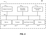
- FIG. 2 illustrates an example block diagram of an example indicia reader 101 in accordance with example embodiments described herein.
- the indicia reader 101 may comprise apparatus 200 shown in FIG. 2 and may include one or more components or modules that are in electronic commutations with one another.
- the apparatus 200 may include an imaging component 202, an illumination component 204, a memory 208, a processor 210, and a communications circuitry 212 that are in electronic communication with one another via a system bus 206.
- the system bus 206 refers to a computer bus that connects these components so as to enable data transfer and communications between these components.
- some or all of these components or modules may be included an engine housed within the indicia reader 101.
- the imaging component 202 may comprise one or more imaging sensors including, but are not limited to, a color or monochrome 1D or 2D Charge Coupled Device (CCD), Complementary Metal-Oxide-Semiconductor (CMOS), N-channel Metal-Oxide-Semiconductor (NMOS), P-channel Metal-Oxide-Semiconductor (PMOS), Charge Injection Device (CID) or Charge Modulation Device (CMD) solid state image sensor, and/or the like.
- the imaging component 202 may include one or more imaging optics that define a field of view for capturing an image of indicia and generating indicia imaging data.
- the illumination component 204 may include one or more illumination sources and one or more illuminating optics assemblies configured to illuminate the field(s) of view of the imaging component 202, so as to improve the quality of the captured indicia imaging data.
- the illumination components 204 may include one or more aimers that provide illumination (e.g., a laser) to indicate where an indica reader 101 is aimed.
- the aimer may be, for example, a green laser (e.g., VLD) or a red laser.
- illuminating optics assemblies may include, but are not limited to, one or more lenses, diffusers, wedges, reflectors, or a combination of such elements, for directing light from illumination source in the direction of the field of view.
- the illuminating optics assembly may be configured to direct light from an illumination source on to the indicia 103.
- the illumination source may include, but are not limited to, laser diodes (e.g., violet laser diodes, visible laser diodes, edge-emitting laser diodes, surface-emitting laser diodes, and/or the like). Additionally, or alternatively, the illumination source may comprise one or more light-emitting diodes (LEDs). Additionally, or alternatively, the illumination source may comprise one or more other forms of natural and/or artificial sources of light.
- the imaging component 202 and/or the illumination component 204 may be controlled by the processor 210.
- the processor 210 may transmit electronic instructions to the illumination component 204 via the system bus 206 to trigger the illumination component 204 to illuminate the field of view of the imaging component 202, may transmit electronic instructions to the imaging component 202 to trigger the imaging component 202 to capture indicia imaging data that include one or more images of the indicia, and may receive the indicia imaging data from the imaging component 202.
- the processor 210 may be embodied in a number of different ways and may, for example, include one or more processing devices configured to perform independently. Additionally, or alternatively, the processor 210 may include one or more processors configured in tandem via a bus to enable independent execution of instructions, pipelining, and/or multithreading.
- processing circuitry may be understood to include a single core processor, a multi-core processor, multiple processors internal to the apparatus, and/or remote or "cloud" processors.
- the processor 210 may be embodied as one or more complex programmable logic devices (CPLDs), microprocessors, multi-core processors, co-processing entities, application-specific instruction-set processors (ASIPs), and/or controllers. Further, the processor 210 may be embodied as one or more other processing devices or circuitry.
- the term circuitry may refer to an entirely hardware embodiment or a combination of hardware and computer program products.
- the processor 210 may be embodied as integrated circuits, application specific integrated circuits (ASICs), field programmable gate arrays (FPGAs), programmable logic arrays (PLAs), hardware accelerators, other circuitry, and/or the like.
- the processor 210 may be configured for a particular use or configured to execute instructions stored in volatile or non-volatile media or otherwise accessible to the processor 210. As such, whether configured by hardware or computer program products, or by a combination thereof, the processor 210 may be capable of performing steps or operations according to embodiments of the present disclosure when configured accordingly.
- the processor 210 may be configured to execute instructions stored in the memory 208 or otherwise accessible to the processor. Alternatively, or additionally, the processor 210 may be configured to execute hard-coded functionality. As such, whether configured by hardware or software methods, or by a combination thereof, the processor may represent an entity (e.g., physically embodied in circuitry) capable of performing operations according to an embodiment of the present disclosure while configured accordingly. Alternatively, as another example, when the processor 210 is embodied as an executor of software instructions, the instructions may specifically configure the processor to perform the algorithms and/or operations described herein when the instructions are executed.
- the memory 208 may be non-transitory and may include, for example, one or more volatile and/or non-volatile memories.
- the memory 208 may be an electronic storage device (e.g., a computer readable storage medium).
- the memory 208 may be configured to store information, data, content, applications, instructions, or the like, for enabling the apparatus 200 to carry out various functions in accordance with example embodiments of the present disclosure.
- the memory 208 may be preconfigured to include computer-coded instructions (e.g., computer program code), and/or dynamically be configured to store such computer-coded instructions for execution by the processor 210.
- the apparatus 200 further includes a communications circuitry 212 that may enable the apparatus 200 to transmit data and/or information to other devices (such as, but not limited to, the connected devices 120A, 120B, ... , 120N as shown in FIG. 1 ) through a communication network.
- the communications circuitry 212 may be any means such as a device or circuitry embodied in either hardware or a combination of hardware and software that is configured to receive and/or transmit data from/to a network and/or any other device, circuitry, or module in communication with the apparatus 200.
- the communications circuitry 212 may include, for example, a network interface for enabling communications with a wired or wireless communication network.
- the communications circuitry 212 may include one or more circuitries, network interface cards, antennae, buses, switches, routers, modems, and supporting hardware and/or software, or any other device suitable for enabling communications via a network.
- the communication interface may include the circuitry for interacting with the antenna(s) to cause transmission of signals via the antenna(s) or to handle receipt of signals received via the antenna(s).
- the apparatus 200 may include the input/output circuitry 214 that may, in turn, be in communication with the processor 210 to provide output to the user and, in some embodiments, to receive an indication of a user input.
- the input/output circuitry 214 may comprise an interface, a mobile application, a kiosk, or the like.
- the input/output circuitry 214 may also include a keyboard, a mouse, a joystick, a touch screen, touch areas, soft keys, a microphone, a speaker, or other input/output mechanisms.
- the processor and/or user interface circuitry comprising the processor may be configured to control one or more functions of one or more user interface elements through computer program instructions (e.g., software and/or firmware) stored on a memory accessible to the processor (e.g., memory 208).
- the input/output circuitry 214 may include a trigger or button that may allow for a user to instruct the indicia reader 101 to capture an image of indicia 103. Additionally, some embodiments may include input/output circuitry 214 such that a user may instruct the indicia reader 101 to select one of multiple imaging optics to utilize, to select one or configure one of multiple illumination components 204 to utilize, and/or to transmit data and/or information to a connected device.
- the apparatus 200 may include the display 216 that may, in turn, be in communication with the processor 210 to display user interfaces (such as, but not limited to, display of indicia or decoded indicia).
- the display 216 may include a liquid crystal display (LCD), a light-emitting diode (LED) display, a plasma (PDP) display, a quantum dot (QLED) display, and/or the like.
- the apparatus 200 may include, but are not limited to, an indicia scanner, a handheld scanner, a camera, and/or any other device that is capable of capturing a plurality of images of the indicia and/or generating indicia imaging data of the indicia. Additionally, or alternatively, the apparatus 200 may be in other form(s) and /or may comprise other component(s).
- the processor 301 may be embodied as one or more complex programmable logic devices (CPLDs), microprocessors, multi-core processors, co-processing entities, application-specific instruction-set processors (ASIPs), and/or controllers. Further, the processor 301 may be embodied as one or more other processing devices or circuitry.
- the term circuitry may refer to an entirely hardware embodiment or a combination of hardware and computer program products.
- the processor 301 may be embodied as integrated circuits, application specific integrated circuits (ASICs), field programmable gate arrays (FPGAs), programmable logic arrays (PLAs), hardware accelerators, other circuitry, and/or the like.
- the processor 301 may be configured for a particular use or configured to execute instructions stored in volatile or non-volatile media or otherwise accessible to the processor 301. As such, whether configured by hardware or computer program products, or by a combination thereof, the processor 301 may be capable of performing steps or operations according to embodiments of the present disclosure when configured accordingly.
- the memory 303 may be non-transitory and may include, for example, one or more volatile and/or non-volatile memories.
- the memory 303 may be an electronic storage device (e.g., a computer readable storage medium).
- the memory 303 may be configured to store information, data, content, applications, instructions, or the like, for enabling the apparatus 300 to carry out various functions in accordance with example embodiments of the present disclosure.
- the memory 303 may be preconfigured to include computer-coded instructions (e.g., computer program code), and/or dynamically be configured to store such computer-coded instructions for execution by the processor 301.
- the processor 301 may be configured to execute instructions stored in the memory 303 or otherwise accessible to the processor. Alternatively, or additionally, the processor 301 may be configured to execute hard-coded functionality. As such, whether configured by hardware or software methods, or by a combination thereof, the processor may represent an entity (e.g., physically embodied in circuitry) capable of performing operations according to an embodiment of the present disclosure while configured accordingly. Alternatively, as another example, when the processor 301 is embodied as an executor of software instructions, the instructions may specifically configure the processor to perform the algorithms and/or operations described herein when the instructions are executed.
- the apparatus 300 may include the input/output circuitry 307 that may, in turn, be in communication with the processor 301 to provide output to the user and, in some embodiments, to receive an indication of a user input.
- the input/output circuitry 307 may comprise an interface, a mobile application, a kiosk, or the like.
- the input/output circuitry 307 may also include a keyboard, a mouse, a joystick, a touch screen, touch areas, soft keys, a microphone, a speaker, or other input/output mechanisms.
- the processor and/or user interface circuitry comprising the processor may be configured to control one or more functions of one or more user interface elements through computer program instructions (e.g., software and/or firmware) stored on a memory accessible to the processor (e.g., memory 303).
- computer program instructions e.g., software and/or firmware
- the apparatus 300 may include a display 309 that may, in turn, be in communication with the processor 301 to display user interfaces (such as, but not limited to, display of indicia or decoded indicia).
- the display 309 may include a liquid crystal display (LCD), a light-emitting diode (LED) display, a plasma (PDP) display, a quantum dot (QLED) display, and/or the like.
- one or more components or modules of FIG. 2 may be located in or on an indicia reader engine, which may be referred to as an engine, in the indicia reader 101.
- FIGS. 4A , 4B , and 4C illustrate different views of an example engine for an indicia reader 101 in accordance with example embodiments described herein.
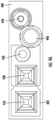
- FIG. 4A illustrates a front view of an example engine 400 for use in an indicia reader 101 in accordance with some embodiments.
- the engine 400 includes an illumination optic 402, a first illumination source 410, a second illumination source 420, an aimer 430, a far field imaging optic 440, and a near field imaging optic 450. While FIG. 4 illustrates a first illumination source 410, a second illumination source 420, and an aimer 430, alternative embodiments may include fewer or additional illumination sources and/or aimers.
- the first illumination source 410 is associated with the far field imaging optic 440 and the second illumination source 420 is associated with the near field imaging optic 450.
- the association is such that when the indicia reader 101 is to capture indicia imaging data from an indicia 103, the indicia reader 101 may illuminate the indicia 103 with the first illumination source 410 when the indicia 103 is in the field of view of the far field imaging optic 440 and/or indicia reader 101 may illuminate the indicia 103 with the second illumination source 420 when the indicia 103 is in the field of view of the near field imaging optic 450.
- the indicia reader 101 may illuminate the indicia 103 with both the first illumination source 410 and the second illumination source 420 when the indicia is in the field of view of the both the far field imaging optic 440 and the near field imaging optic 450.
- the location of the indicia 103 may be determined by a ranging component (not depicted), which may or may not operate in conjunction with the aimer 430.
- the indicia reader 101 may alternate between the first illumination source 410 and the second illumination source 420 when capturing indicia imaging data from an indicia 103, and in such an embodiment the indicia reader 101 may determine which indicia imaging data that has been captured to use based on a quality of image data decoded.
- illumination optic 402 there may be combinations of more than one illumination optics associated with combinations of one or more illumination sources (e.g., 410, 420) and aimer (430).
- the illumination optic 402 may be comprised of one or more optical elements.
- Each of the far field imaging optic 440 and the near field imaging optic 450 may each include a barrel containing one or more optical elements (e.g., one or more lenses of various types (e.g., convex, concave, etc.)) and/or one or more filters (e.g., IR filter).
- a barrel may also contain one or more retainers and/or spacers to separate optical elements and/or filters at a specified distance.
- a filter may be located at the either end of the barrel or in the middle of the barrel, which may be between two or more optical elements.
- a barrel may also be shaped to accommodate one or more optical elements separate from another optical element by the inner diameter of the barrel increasing or decreasing over the length of the barrel. The outer diameter may increase or decrease over the length of the barrel.
- outer diameter of the barrel of the far field imaging optic 440 may be larger at the distal end and smaller at the proximal end while the barrel of the near field imaging optic 450 may be smaller at the distal end and larger at the proximal end such that portions of the barrels may overlap, which may allow for a stacked and/or nested configuration.
- a stacked configuration may include one or more portions (e.g., a barrel) of a first optic to be stacked on top of or in front of one or more portions of a second optic (e.g., a barrel).
- a nested configuration may include or more portions of a first optic (e.g., its barrel) to be configured to be arranged in the space of one or more portions of a second optic (e.g., its barrel).
- a first optic e.g., its barrel
- a second optic e.g., its barrel
- such configurations may provide for improvements by allowing for, among other things, the optical axis of the far field imaging optic 440 and the optical axis of the near field imaging optic 450 closer together and thus reduce the offset between these axes.
- the barrel outer diameter of the far field imaging optic 440 may be larger in front and smaller in back, and the barrel out diameter of the near field imaging optic 450 may be smaller in front and larger in back.
- These two barrel shapes are complementary to allow the barrels to nest in each other, such as may be readily seen from FIGS. 4A , 6 , and 7 .
- the barrel of one of the optics may include a cut-out or accommodation to allow for a nesting of a portion of the barrel of the other optic to be nested.
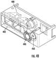
- FIG. 4B illustrates an angled view of the front of an example engine 400 in accordance with some embodiments.
- FIG. 4B illustrates the illumination optic 402 (illustrated with broken lines) in engine 400 and the far field imaging optic 440 and the near field imaging optic 450 on the front of the engine.
- the illumination optic 402 may consist of three portions: a first illumination source 410 portion, a second illumination source 420 portion, and an aimer 430 portion.
- the front of each portion may have a different shape.
- the front of the first illumination source 410 portion and the second illumination source 420 portion may be convex and the aimer 320 portion may be a different shape.
- the first illumination source 410 portion and the second illumination source 420 portion may include light pipe to conduct and distribute light from the respective sources to the front of the respective portions of the illumination optic 402.
- the illumination optic 402 may one solid piece (e.g., formed from injection molded plastic). In alternative embodiments, the illumination optic 402 may include a plurality of optical elements.
- FIG. 4C illustrates an angled view of the rear of an example engine 400 in accordance with some embodiments.
- FIG. 4C illustrates a printed circuit board (PCB) 470, and a connector 460 on the rear side of the PCB 470.
- connector 460 may be an electrical connector with one or more pin to mate to a complimentary connector from another component or module of indicia reader 101.
- FIG. 6 illustrates a view of an example engine for an indicia reader in accordance with example embodiments described herein.
- the engine 400 is illustrated in an exploded view to illustrate the illumination optic 402, the far field imaging optic 440, and the near field imaging optic 450 in addition to PCB 470 and the first illumination source 410, second illumination source 420, aimer 430, imaging sensor array 610 on the front of PCB 470.
- a first mirror 620A and a second mirror 620B which will be readily appreciated to be located in engine 400.
- the chassis of engine 400 may include one or more slots for seating each of the mirrors.
- mirrors 620A, 620B may not be mirrors and may alternatively be one or more optical elements to direct light, including but not limited to prisms.
- more than one periscope configuration may be used such that the embodiment may have more than two imaging optics, and each of the imaging optics may have its own portion of the imaging sensor array 610.
- FIG. 7 illustrates a top-down view of components of an engine 400 for an indicia reader in accordance with example embodiments described herein.
- the chassis of the engine 400 is not present and the components of the engine 400 are illustrated.
- FIG. 7 illustrates an embodiment where the imaging sensor array 610 is shared between the far field imaging optic 440 and the near field imaging optic 450.
- the near field imaging optic 450 is positioned in front of the imaging sensor array 610 and the far field imaging optic 440 is placed adjacent to the near field imaging optic 450 with mirrors 620A, 620B configured to provide a periscope configuration for the far field imaging optic 440.
- the near field optical field of view is illustrated at reference 520B and the optical path for the near field imaging optic 450 from the near field imaging optic 450 to the imaging sensor array 610 is depicted at 520A.
- the far field optical field of view is illustrated at reference 530B and the optical path from the far field imaging optic 440 to the imaging sensor array 610 is depicted at 530A as from far field imaging optic 400 to mirror 620B to mirror 620A to imaging sensor array 610.
- Both optical path 520A and optical path 530A are directed to the imaging sensor array 610, though these are not overlapping optical paths due to the imaging sensor array 610 being split by these two optical paths 520A and 530A as each optical path is incident on the imaging sensor array 610.
- the optical axes of the aimer 430, of the far field imaging optic 440, and of the near field imaging optic 450 are parallel, and these optical axes are all perpendicular to the plane of the imaging sensor array 610.
- FIG. 8 illustrates an example circuit board for an indicia reader in accordance with example embodiments described herein.
- the first illumination source 410, the second illumination source 420, the aimer 430, and the imaging sensor array 610 may be mounted of the front side of PCB 470.
- FIG. 9 illustrates an example process for an indicia reader in accordance with example embodiments described herein.
- the indicia reader 101 may capture, decode, and transmit indicia imaging data or indicia information as described in FIG. 9 .
- the process of FIG. 9 may start at 902 and may end at 912. In some embodiments, one or more operations may be omitted. Additionally, other operations may be added to the process.
- the indicia reader 101 may capture indicia imaging data from an indicia 103.
- the user may pull a trigger or press a button to cause the indicia reader to capture the indicia imaging data. Capturing indicia imaging data is further described herein.
- the indicia reader 101 may decode the indicia imaging data into indicia information.
- the indicia reader 101 may decode an indicia, such as but not limited to a barcode or QR code.
- the indicia reader 101 may transmit the decoded indicia imaging data or indicia information to one or more other connected devices 120. Additionally, or alternatively, the transmission may include transmitted the captured indicia imaging data.
- the indicia reader 101 may use a first illumination source 420 to illuminate the indicia 103.
- the first illumination source 410 may be associated with the far field imaging optic 440.
- the first illumination source 410 may be dedicated to operation with the far field imaging optic 440.
- some embodiments may have a first illumination source associated with both the far field imaging optic 440 and the near field imaging optic 450.
- Embodiments of the subject matter described herein may be implemented as one or more computer programs, i.e., one or more modules of computer program instructions, encoded on computer storage medium for execution by, or to control the operation of, information/data processing apparatus.
- the program instructions can be encoded on an artificially-generated propagated signal, e.g., a machine-generated electrical, optical, or electromagnetic signal, which is generated to encode information/data for transmission to suitable receiver apparatus for execution by an information/data processing apparatus.
- a computer storage medium can be, or be included in, a computer-readable storage device, a computer-readable storage substrate, a random or serial access memory array or device, or a combination of one or more of them.
- a computer storage medium is not a propagated signal
- a computer storage medium can be a source or destination of computer program instructions encoded in an artificially-generated propagated signal.
- the computer storage medium can also be, or be included in, one or more separate physical components or media (e.g., multiple CDs, disks, or other storage devices).
- the operations described herein can be implemented as operations performed by an information/data processing apparatus on information/data stored on one or more computer-readable storage devices or received from other sources.
- processors suitable for the execution of a computer program include, by way of example, both general and special purpose microprocessors, and any one or more processors of any kind of digital computer.
- a processor will receive instructions and information/data from a read-only memory or a random access memory or both.
- the essential elements of a computer are a processor for performing actions in accordance with instructions and one or more memory devices for storing instructions and data.
- the term "data processing apparatus” as used above encompasses all kinds of apparatus, devices, and machines for processing data, including by way of example a programmable processor, a computer, a system on a chip, or multiple ones, or combinations, of the foregoing.
- the apparatus may include special purpose logic circuitry, e.g., an FPGA (field programmable gate array) or an ASIC (application-specific integrated circuit).
- the apparatus may also include, in addition to hardware, code that creates an execution environment for the computer program in question, e.g., code that constitutes processor firmware, a protocol stack, a repository management system, an operating system, a cross-platform runtime environment, a virtual machine, or a combination of one or more of them.
- the apparatus and execution environment may realize various different computing model infrastructures, such as web services, distributed computing, and grid computing infrastructures.
- Computer software or computer program (also known as a program, software, software application, script, or code) can be written in any form of programming language, including compiled or interpreted languages, declarative or procedural languages, and it can be deployed in any form, including as a stand-alone program or as a module, component, subroutine, object, or other unit suitable for use in a computing environment.
- a computer program may, but need not, correspond to a file in a file system.
Landscapes
- Physics & Mathematics (AREA)
- Engineering & Computer Science (AREA)
- Electromagnetism (AREA)
- General Physics & Mathematics (AREA)
- Theoretical Computer Science (AREA)
- General Health & Medical Sciences (AREA)
- Health & Medical Sciences (AREA)
- Toxicology (AREA)
- Artificial Intelligence (AREA)
- Computer Vision & Pattern Recognition (AREA)
- Quality & Reliability (AREA)
- Character Input (AREA)
- Image Input (AREA)
Applications Claiming Priority (1)
| Application Number | Priority Date | Filing Date | Title |
|---|---|---|---|
| US17/846,470 US12026583B2 (en) | 2022-06-22 | 2022-06-22 | One sensor near far solution to minimize FOV mismatch and aiming offsets |
Publications (1)
| Publication Number | Publication Date |
|---|---|
| EP4296884A1 true EP4296884A1 (de) | 2023-12-27 |
Family
ID=86497402
Family Applications (1)
| Application Number | Title | Priority Date | Filing Date |
|---|---|---|---|
| EP23174734.6A Pending EP4296884A1 (de) | 2022-06-22 | 2023-05-23 | Fernnahe lösung mit einem sensor zur minimierung von fov-fehlanpassungen und zieloffsets |
Country Status (3)
| Country | Link |
|---|---|
| US (2) | US12026583B2 (de) |
| EP (1) | EP4296884A1 (de) |
| CN (1) | CN117273028A (de) |
Citations (5)
| Publication number | Priority date | Publication date | Assignee | Title |
|---|---|---|---|---|
| EP2030067A2 (de) * | 2006-06-20 | 2009-03-04 | Datalogic Scanning, Inc. | Abbildungsscanner mit mehreren bildfeldern |
| US20110186636A1 (en) * | 2010-02-01 | 2011-08-04 | Ryan Hyde | Imaging engine with multi-functional structure |
| US20150347799A1 (en) * | 2014-05-30 | 2015-12-03 | Datalogic ADC, Inc. | Extended depth of field in imaging machine-readable symbol reader using image side telecentric lens |
| US20190243998A1 (en) * | 2012-10-04 | 2019-08-08 | The Code Corporation | A barcode reading accessory for a mobile device including a one-way mirror |
| EP3822702A1 (de) * | 2019-11-14 | 2021-05-19 | Hand Held Products, Inc. | Abbildungsgeräte mit integrierter beleuchtungszieleinrichtung |
Family Cites Families (23)
| Publication number | Priority date | Publication date | Assignee | Title |
|---|---|---|---|---|
| US6736321B2 (en) * | 1995-12-18 | 2004-05-18 | Metrologic Instruments, Inc. | Planar laser illumination and imaging (PLIIM) system employing wavefront control methods for reducing the power of speckle-pattern noise digital images acquired by said system |
| US7051922B2 (en) * | 1994-08-17 | 2006-05-30 | Metrologic Instruments, Inc. | Compact bioptical laser scanning system |
| WO1998000806A1 (en) * | 1996-06-28 | 1998-01-08 | Battelle Memorial Institute | Edge effect compensating bar code reader |
| US6053408A (en) | 1997-12-02 | 2000-04-25 | Telxon Corporation | Multi-focal length imaging based portable dataform reader |
| US6918540B2 (en) * | 2000-04-18 | 2005-07-19 | Metrologic Instruments, Inc. | Bioptical point-of-sale (pos) scanning system employing dual polygon-based laser scanning platforms disposed beneath horizontal and vertical scanning windows for 360° omni-directional bar code scanning |
| US6818907B2 (en) * | 2000-10-17 | 2004-11-16 | The President And Fellows Of Harvard College | Surface plasmon enhanced illumination system |
| US7708205B2 (en) * | 2003-11-13 | 2010-05-04 | Metrologic Instruments, Inc. | Digital image capture and processing system employing multi-layer software-based system architecture permitting modification and/or extension of system features and functions by way of third party code plug-ins |
| US7490774B2 (en) * | 2003-11-13 | 2009-02-17 | Metrologic Instruments, Inc. | Hand-supportable imaging based bar code symbol reader employing automatic light exposure measurement and illumination control subsystem integrated therein |
| US20080099667A1 (en) * | 2001-08-14 | 2008-05-01 | President And Fellows Of Harvard College | Methods and apparatus for sensing a physical substance |
| US7086596B2 (en) | 2003-01-09 | 2006-08-08 | Hand Held Products, Inc. | Decoder board for an optical reader utilizing a plurality of imaging formats |
| US7014113B1 (en) | 2002-08-19 | 2006-03-21 | The Code Corporation | Versatile graphical code reader for reading different types of graphical codes |
| US20060042321A1 (en) * | 2002-11-06 | 2006-03-02 | Aaron Lewis | Integrated simulation fabrication and characterization of micro and nano optical elements |
| US20080192004A1 (en) * | 2007-02-08 | 2008-08-14 | Silverbrook Research Pty Ltd | System for scrolling page displayed on a display device |
| US20080283603A1 (en) * | 2007-05-14 | 2008-11-20 | Peter Barron | Barcode scanner operator interface |
| US20110180602A1 (en) * | 2010-01-27 | 2011-07-28 | Silverbrook Research Pty Ltd | Method of imaging coding pattern using variant registration codewords |
| US20110180612A1 (en) * | 2010-01-27 | 2011-07-28 | Silverbrook Research Pty Ltd | Coding pattern comprising multi-ppm data symbols with minimal clustering of macrodots |
| US20130068839A1 (en) * | 2011-09-21 | 2013-03-21 | Symbol Technologies, Inc. | Method of and apparatus for imaging targets by utilizing multiple imaging modules with on-board local microprocessors |
| US8864034B1 (en) | 2013-07-19 | 2014-10-21 | The Code Corporation | Barcode reader having multiple illumination systems and multiple sets of imaging optics |
| EP3221727B1 (de) * | 2014-11-19 | 2021-03-17 | Trumpf Laser- und Systemtechnik GmbH | System zur asymmetrischen optischen strahlformung |
| DE102014116958B9 (de) * | 2014-11-19 | 2017-10-05 | Trumpf Laser- Und Systemtechnik Gmbh | Optisches System zur Strahlformung eines Laserstrahls, Laserbearbeitungsanlage, Verfahren zur Materialbearbeitung und Verwenden einer gemeinsamen langgezogenen Fokuszone zur Lasermaterialbearbeitung |
| WO2020123842A1 (en) * | 2018-12-12 | 2020-06-18 | Drake Precision Optics, Inc. | Ophthalmic surgery laser system and method for utilizing same for ophthalmic surgery |
| US11036944B1 (en) * | 2020-02-04 | 2021-06-15 | Hand Held Products, Inc. | Alternative illuminator assembly and mobile imaging apparatus for improved direct part marking reading |
| JP7585099B2 (ja) * | 2021-03-10 | 2024-11-18 | 東芝テック株式会社 | コード読取装置及びそのプログラム、コード読取システム並びにコード読取方法 |
-
2022
- 2022-06-22 US US17/846,470 patent/US12026583B2/en active Active
-
2023
- 2023-05-23 EP EP23174734.6A patent/EP4296884A1/de active Pending
- 2023-06-07 CN CN202310667566.9A patent/CN117273028A/zh active Pending
-
2024
- 2024-05-17 US US18/667,212 patent/US12437172B2/en active Active
Patent Citations (6)
| Publication number | Priority date | Publication date | Assignee | Title |
|---|---|---|---|---|
| EP2030067A2 (de) * | 2006-06-20 | 2009-03-04 | Datalogic Scanning, Inc. | Abbildungsscanner mit mehreren bildfeldern |
| EP2030067B1 (de) * | 2006-06-20 | 2023-05-31 | Datalogic USA, Inc. | Abbildungsscanner mit mehreren bildfeldern |
| US20110186636A1 (en) * | 2010-02-01 | 2011-08-04 | Ryan Hyde | Imaging engine with multi-functional structure |
| US20190243998A1 (en) * | 2012-10-04 | 2019-08-08 | The Code Corporation | A barcode reading accessory for a mobile device including a one-way mirror |
| US20150347799A1 (en) * | 2014-05-30 | 2015-12-03 | Datalogic ADC, Inc. | Extended depth of field in imaging machine-readable symbol reader using image side telecentric lens |
| EP3822702A1 (de) * | 2019-11-14 | 2021-05-19 | Hand Held Products, Inc. | Abbildungsgeräte mit integrierter beleuchtungszieleinrichtung |
Also Published As
| Publication number | Publication date |
|---|---|
| US12437172B2 (en) | 2025-10-07 |
| US12026583B2 (en) | 2024-07-02 |
| US20240303454A1 (en) | 2024-09-12 |
| US20230419064A1 (en) | 2023-12-28 |
| CN117273028A (zh) | 2023-12-22 |
Similar Documents
| Publication | Publication Date | Title |
|---|---|---|
| EP3667554B1 (de) | Abnehmbares abtastungsmodul für ein mobiles kommunikationsendgerät | |
| US9626544B2 (en) | Removable module for mobile communication terminal | |
| CN102547108B (zh) | 自动聚焦光学成像装置 | |
| EP3040906B1 (de) | Visuelle rückmeldung für codeleser | |
| US9477867B2 (en) | System and method to manipulate an image | |
| US9053378B1 (en) | Laser barcode scanner | |
| CN102334130B (zh) | 具有双功能照明光组件的成像读取器和方法 | |
| EP3076330A1 (de) | Zieleinrichtung zum strichcodescannen | |
| US7699227B2 (en) | Optical reader | |
| EP2218036A1 (de) | Cpc-beleuchtungsgerät für einen strichcodeleser auf bildgebungsbasis | |
| EP4296884A1 (de) | Fernnahe lösung mit einem sensor zur minimierung von fov-fehlanpassungen und zieloffsets | |
| US7878406B2 (en) | Optical reader | |
| EP4020961B1 (de) | Verfahren und gerät zur abbildung unter verwendung einer doppelzweck-beleuchtungsvorrichtung | |
| US9311514B2 (en) | Imaging barcode scanner with multiple independent fields of view | |
| EP4722974A1 (de) | Optische anordnung, optische linse und bildgebungsleser | |
| EP4428746A1 (de) | Optische anordnung, bildgebungsleser und verfahren zur beleuchtung mit zwei linsen | |
| US9082029B2 (en) | Optical code scanner with a high dispersion optical lens | |
| US12073286B2 (en) | Methods, apparatuses and computer program products for providing artificial-intelligence-based indicia data editing | |
| EP4332829A1 (de) | Fast koaxial polarisierte beleuchtungsvorrichtungen und verwendungen davon | |
| US12505324B1 (en) | Illumination system to improve scanner performance in dark environments | |
| EP2151121A2 (de) | Bildlesesystem |
Legal Events
| Date | Code | Title | Description |
|---|---|---|---|
| PUAI | Public reference made under article 153(3) epc to a published international application that has entered the european phase |
Free format text: ORIGINAL CODE: 0009012 |
|
| STAA | Information on the status of an ep patent application or granted ep patent |
Free format text: STATUS: REQUEST FOR EXAMINATION WAS MADE |
|
| 17P | Request for examination filed |
Effective date: 20230523 |
|
| AK | Designated contracting states |
Kind code of ref document: A1 Designated state(s): AL AT BE BG CH CY CZ DE DK EE ES FI FR GB GR HR HU IE IS IT LI LT LU LV MC ME MK MT NL NO PL PT RO RS SE SI SK SM TR |
|
| RAP3 | Party data changed (applicant data changed or rights of an application transferred) |
Owner name: HAND HELD PRODUCTS, INC. |
|
| STAA | Information on the status of an ep patent application or granted ep patent |
Free format text: STATUS: EXAMINATION IS IN PROGRESS |
|
| 17Q | First examination report despatched |
Effective date: 20250506 |