EP4296881A1 - Systolic array-based data processing method, apparatus, medium, and program product - Google Patents
Systolic array-based data processing method, apparatus, medium, and program product Download PDFInfo
- Publication number
- EP4296881A1 EP4296881A1 EP22758836.5A EP22758836A EP4296881A1 EP 4296881 A1 EP4296881 A1 EP 4296881A1 EP 22758836 A EP22758836 A EP 22758836A EP 4296881 A1 EP4296881 A1 EP 4296881A1
- Authority
- EP
- European Patent Office
- Prior art keywords
- input
- output
- input data
- data items
- group
- Prior art date
- Legal status (The legal status is an assumption and is not a legal conclusion. Google has not performed a legal analysis and makes no representation as to the accuracy of the status listed.)
- Pending
Links
- 238000003672 processing method Methods 0.000 title claims abstract description 44
- 238000000034 method Methods 0.000 claims abstract description 67
- 238000004364 calculation method Methods 0.000 claims description 526
- 239000000872 buffer Substances 0.000 claims description 344
- 230000008569 process Effects 0.000 claims description 45
- 238000004590 computer program Methods 0.000 claims description 2
- 238000013508 migration Methods 0.000 abstract 1
- 230000005012 migration Effects 0.000 abstract 1
- 238000010586 diagram Methods 0.000 description 13
- 238000013527 convolutional neural network Methods 0.000 description 12
- 239000011159 matrix material Substances 0.000 description 12
- 230000006870 function Effects 0.000 description 9
- 238000013135 deep learning Methods 0.000 description 4
- 238000003491 array Methods 0.000 description 3
- 238000013473 artificial intelligence Methods 0.000 description 3
- 230000003139 buffering effect Effects 0.000 description 3
- 238000013528 artificial neural network Methods 0.000 description 2
- 230000008901 benefit Effects 0.000 description 2
- 230000005540 biological transmission Effects 0.000 description 2
- 238000012986 modification Methods 0.000 description 2
- 230000004048 modification Effects 0.000 description 2
- 238000011176 pooling Methods 0.000 description 2
- 238000009825 accumulation Methods 0.000 description 1
- 230000004913 activation Effects 0.000 description 1
- 230000017531 blood circulation Effects 0.000 description 1
- 238000013500 data storage Methods 0.000 description 1
- 238000010801 machine learning Methods 0.000 description 1
- 230000003287 optical effect Effects 0.000 description 1
- 238000005457 optimization Methods 0.000 description 1
- 230000009467 reduction Effects 0.000 description 1
- 230000011218 segmentation Effects 0.000 description 1
Images


Classifications
-
- G—PHYSICS
- G06—COMPUTING; CALCULATING OR COUNTING
- G06F—ELECTRIC DIGITAL DATA PROCESSING
- G06F15/00—Digital computers in general; Data processing equipment in general
- G06F15/76—Architectures of general purpose stored program computers
- G06F15/80—Architectures of general purpose stored program computers comprising an array of processing units with common control, e.g. single instruction multiple data processors
- G06F15/8046—Systolic arrays
-
- G—PHYSICS
- G06—COMPUTING; CALCULATING OR COUNTING
- G06F—ELECTRIC DIGITAL DATA PROCESSING
- G06F30/00—Computer-aided design [CAD]
- G06F30/20—Design optimisation, verification or simulation
- G06F30/27—Design optimisation, verification or simulation using machine learning, e.g. artificial intelligence, neural networks, support vector machines [SVM] or training a model
-
- G—PHYSICS
- G06—COMPUTING; CALCULATING OR COUNTING
- G06F—ELECTRIC DIGITAL DATA PROCESSING
- G06F9/00—Arrangements for program control, e.g. control units
- G06F9/06—Arrangements for program control, e.g. control units using stored programs, i.e. using an internal store of processing equipment to receive or retain programs
- G06F9/46—Multiprogramming arrangements
- G06F9/54—Interprogram communication
- G06F9/544—Buffers; Shared memory; Pipes
-
- G—PHYSICS
- G06—COMPUTING; CALCULATING OR COUNTING
- G06N—COMPUTING ARRANGEMENTS BASED ON SPECIFIC COMPUTATIONAL MODELS
- G06N3/00—Computing arrangements based on biological models
- G06N3/02—Neural networks
- G06N3/06—Physical realisation, i.e. hardware implementation of neural networks, neurons or parts of neurons
- G06N3/063—Physical realisation, i.e. hardware implementation of neural networks, neurons or parts of neurons using electronic means
Definitions
- the present disclosure relates to the computer field, and more specifically, to a systolic array-based data processing method and apparatus, a medium, and a program product.
- CNN convolutional neural network
- the systolic array structure includes calculation units (denoted as PEs, each PE including a multiplier-accumulator or a similar calculation device, and/or a storage unit) disposed at nodes of each row and each column.
- PEs calculation units
- An advantage lies in that an operand or an intermediate result participating in an internal operation can participate in a high-speed parallel pipeline manner, that is, simple and efficient systolic transfer can be implemented for each piece of input data (data inputted to each row) and a calculation result of each PE in the entire array, thereby improving data reuse, reducing off-chip data transfer, and reducing a bandwidth requirement. Therefore, one or more two-dimensional systolic arrays are widely used in artificial intelligence (AI) processors as a calculation core for multiply-accumulate operations, for example, a TPU.
- AI artificial intelligence
- embodiments of the present disclosure provide a systolic array-based data processing method and apparatus, a medium, and a program product.
- a systolic array-based data processing method including: obtaining a first input depth of the systolic array and a first output depth of the systolic array, and obtaining a second input depth of a shallow depth model and a second output depth of the shallow depth model; determining an input splice quantity for the systolic array based on the second input depth and the first input depth, and determining an output splice quantity for the systolic array based on the second output depth and the first output depth; generating a group of input data items with the input splice quantity, each input data item of the group of input data items having the second input depth; inputting the group of input data items to an input buffer of the systolic array ; processing, by the systolic array, the group of input data items in the input buffer to generate a group of output data items corresponding to the group of input data items, each output data item of the group
- a calculation apparatus may include: a controller, a data fetcher, a systolic array, an input buffer, and an output buffer; wherein the controller is configured to: obtain a first input depth of the systolic array and a first output depth of the systolic array, and obtain a second input depth of a shallow depth model and a second output depth of the shallow depth model; determine an input splice quantity for the systolic array based on the second input depth and the first input depth, and determine an output splice quantity for the systolic array based on the second output depth and the first output depth; generate a group of input data items with the input splice quantity, each input data item of the group of input data items having the second input depth; input the group of input data items to an input buffer of the systolic array; process, by the systolic array, the group of input data items in the input buffer to
- a computer-readable storage medium is further provided, storing an instruction or code, the instruction or code, when executed by a processor, implementing the foregoing operations performed by the controller in the calculation apparatus.
- a computer program product having an instruction or code, the data processing method above being implemented for a case that the instruction or the code is executed by a calculation apparatus.
- Deep learning also referred to as deep structured learning or hierarchical learning
- Learning may be supervised, semi-supervised, or unsupervised.
- the convolutional neural network mainly includes an input layer, a convolutional layer, an activation function, a pooling layer, a fully connected layer, and a loss function, and there may be a plurality of intermediate layers (for example, convolutional layers and pooling layers).
- a systolic array structure may be used for implementing a calculation process at the convolutional layer.
- the systolic array structure may be alternatively applied to calculation of any matrix.
- Shallow depth model a lightweight model used in deep learning for generating output data based on input data, depths of the input data and the output data being generally small.
- a calculation process of the shallow depth model is implemented based on a systolic array described below.
- a systolic array has a plurality of calculation units arranged in rows and columns.
- a calculation unit includes a calculation element such as a multiply-accumulate unit (for example, implemented by a multiplier-accumulator), to perform matrix multiplication as a basic calculation unit of a neural network.
- the calculation units are connected to each other through wires. After necessary buffers are integrated in the calculation units, the buffers are connected to buffers outside the calculation units.
- a systolic matrix is named after a systolic function of a heart: Like blood flow, data is "pumped" by the calculation units.
- FIG. 1 is a schematic structural diagram of a systolic array-based calculation apparatus 100 according to an embodiment of the present disclosure.
- the calculation apparatus 100 includes: a controller 101, a data fetcher 102, a systolic array 103, an input buffer 104, and an output buffer 105.
- controller 101 may be a general term for a plurality of control modules that cooperate with each other to control all operations of the calculation apparatus 100.
- the controller 101 herein may be one or more of a global controller for global control, various types of control logic or control circuits for controlling operations of the data fetcher, the input buffer, and the output buffer, and the like; or may be a combination of multiplier-accumulators in calculation units.
- the global controller may be configured with, for example, instruction parsing and parameter configuration functions, to provide operating parameters for the data fetcher 102, the input buffer 104, the output buffer 105, and the like.
- Control logic corresponding to the input buffer 104 may control transmission of buffered input data to the systolic array 103.
- Control logic corresponding to the output buffer may control buffering of output data of the systolic array 103 to the output buffer, and output the output data from the output buffer.
- the systolic array 103 may be a calculation unit array (also used interchangeably with the systolic array in the following descriptions), and may have a first input depth and a first output depth.
- a quantity of rows and a quantity of columns of the calculation unit array correspond to the first input depth and the first output depth respectively.
- the first input depth is the quantity of rows of the calculation unit array
- the first output depth is the quantity of columns of the calculation unit array.
- the quantity of rows and the quantity of columns of the calculation unit array may be equal to the first input depth and the first output depth may respectively.
- the quantity of rows and the quantity of columns of the calculation unit array may be greater than the first input depth and the first output depth respectively, so that calculation units in some rows and columns serve as alternatives or redundancy. This is not limited in the present disclosure.
- the first input depth and the first output depth of the calculation unit array may be different. For example, for different types of AI processors including calculation unit arrays, calculation unit arrays 16 ⁇ 32, 32 ⁇ 32, and the like may be selected.
- the calculation unit array (systolic array) 103 may include at least one row of calculation units, each row of calculation units includes at least two calculation units 103a, and two adjacent calculation units 103a in each row of calculation units are connected.
- the input buffer 104 buffers at least one input data item that comes from the data fetcher 102 and that requires calculation by the systolic array.
- An input data item may be one or more pieces of data.
- an input to a shallow depth model i.e., an input required to execute a shallow depth model one time
- a process of using one input by the shallow depth model to obtain an output may be considered as executing the shallow depth model once.
- the input buffer 104 may also buffer calculation parameters used for calculation. The calculation parameters may be provided by the data fetcher 102 directly to the systolic array 103 or provided to the systolic array 103 through the input buffer 104.
- Each input data item may also have a depth (which may be considered as including one or more pieces of input data or single or multi-channel input data).
- the depth of the input data item represents a quantity of rows of calculation units to be required for the input data item. Since each piece of input data included in the input data item may only use a row of calculation units in the systolic array 103, the quantity of all pieces of input data in one input data item is equal to the depth of one input data item.
- the input buffer 104 may include a plurality (for example, equal to the quantity of rows of the systolic array) of input sub-buffers (not shown), and each input sub-buffer is configured to provide a piece of input data to calculation units in a row of the systolic array.
- the input data item may be considered as including m pieces of input data or input data of m channels, and the m pieces of input data are buffered to the m input sub-buffers respectively according to an input format and a time sequence required for the systolic array, so that the m input sub-buffers input the m pieces of input data to m rows of the systolic array respectively according to the time sequence of the systolic array.
- the controller 101 may control input of input data in the input buffer 104 to a calculation unit 103a in a corresponding row, and a calculation unit 103a in each row transmits each piece of received input data in the calculation unit 103a in the corresponding row.
- a calculation unit 103a in the first column of the first row receives a piece of input data from the first input sub-buffer
- the calculation unit transfers the input data to a calculation unit in the second column of the first row, and the input data is sequentially transferred in a systolic manner.
- a difference between times at which first calculation units 103a in adjacent rows each receive a piece of input data in the input data item is one clock.
- Each calculation unit 103a in the systolic array 103 is configured to calculate a piece of received input data and a corresponding calculation parameter (for example, a weight coefficient of a convolution kernel in a CNN model). For each column of the systolic array 103, calculation results of all calculation units 103a in the column are superposed (that is, accumulated for summation) (from bottom to top in the figure), and a piece of output data is obtained at the last calculation unit 103a in each column (the m th row of each column), so that the piece of output data of the column is outputted to the output buffer 105.
- a corresponding calculation parameter for example, a weight coefficient of a convolution kernel in a CNN model.
- the calculation parameter may be updated as needed, provided that the calculation parameter can be used by a corresponding calculation unit for a case that each calculation unit of the systolic array performs a calculation task.
- a calculation parameter at each calculation unit may be prestored on the calculation unit, or may be transferred to each calculation unit in a systolic manner during calculation according to a clock the same as that of systolic transfer of input data and according to a direction different from that of systolic transfer of input data (the directions being perpendicular). This is the same as a general principle of the systolic array.
- the output buffer 105 may include a plurality of output sub-buffers, configured to buffer output data outputted by the last calculation unit 103a in each column.
- the controller 101 (for example, the control logic corresponding to the output buffer) may control batch output of the output data from the output buffer 105 (or the plurality of output sub-buffers). For example, the output data is provided to a subsequent storage apparatus, or the data is transferred from the output buffer 105 to the input buffer 104 to prepare for a subsequent operation.
- the CNN model is used as an example.
- Each piece of input data inputted to each calculation unit and a convolution kernel provided at the calculation unit each may be a two-dimensional data matrix.
- an image processing process is performed by using the CNN model, and a convolution kernel is a feature weight in the CNN model.
- input data is an image feature map tensor (stored in an NHWC format, N being a quantity of images in this batch of images, H being a quantity of pixels in vertical direction of an image, W being a quantity of pixels in a horizontal direction, and C being a quantity of channels).
- each piece of input data is feature data extracted from the image, and may be represented by the quantity H of pixels in the vertical direction, the quantity W of pixels in the horizontal direction, and the quantity C of channels.
- Each piece of input data in an input data item may be a 10 (H) ⁇ 10 (W) data matrix.
- the data matrix is divided into 10 rows, and each row includes 10 data elements.
- each convolution kernel may be a 3 ⁇ 3 weight matrix.
- the weight matrix is divided into three rows, each row includes three weight elements, and each weight element is a weight value to be multiplied by a data element.
- the input data and the convolution kernel are described only by using two-dimensional data as an example. In actual application, the input data and the convolution kernel may be alternatively three-dimensional data.
- each calculation unit in a row of calculation units prestores a respective calculation parameter.
- a piece of input data corresponding to a row of calculation units may be sequentially inputted to each calculation unit in the row of calculation units in a pipeline manner, and calculation is performed on the input data and a corresponding calculation parameter in each calculation unit.
- the foregoing describes a schematic structural diagram and a general calculation process of the systolic array-based calculation apparatus 100 provided in this embodiment of the present disclosure with reference to FIG. 1 .
- the calculation apparatus 100 may implement multi-depth parallel calculation for input data, so that multiply-accumulate operations such as convolutional calculation can be accelerated.
- utilization efficiency of the systolic array structure and transfer efficiency of transferring input data to an input buffer and fetching output data calculated by a systolic array from an output buffer corresponding to the systolic array are factors that usually need to be considered in the calculation process.
- input data depths and output data depths of different models may be different, and may vary within a specific range.
- an input data depth and an output data depth value of a lightweight model (a shallow depth model) (which are referred to as a second input depth of the shallow depth model and a second output depth of the shallow depth model) are small, for example, 16 or 8.
- a first input depth and a first output depth of a systolic array are, for example, 32
- the systolic array-based calculation process described with reference to FIG. 1 results in a significant reduction in utilization of the systolic array.
- the first input depth and the first output depth of the systolic array are both 32 and the input depth and the output depth of the shallow depth model are both 8
- only calculation results of calculation units in 8 rows ⁇ 8 columns of the 32 ⁇ 32 systolic array are valid (24 pieces of input data inputted to remaining 24 rows are filled with 0s). Therefore, utilization efficiency of calculation units in the systolic array is reduced to 1/16, which seriously affects performance.
- embodiments of the present disclosure provide a data processing method and a calculation apparatus based on a shallow depth model of a systolic array.
- different input data items and/or different output data items are spliced according to a second input depth and a second output depth of the shallow depth model.
- different input data items can be inputted to an input buffer in parallel, and then different input data items is provided to the systolic array.
- different output data items can be outputted from the output buffer in batches, so that transfer efficiency of input/output data can be improved.
- data of each row is transferred between adjacent calculation units in a systolic manner, and calculation results of calculation units in each column are transferred between adjacent calculation units in a systolic manner and accumulated, so that most calculation units in the systolic array can always be in a calculation state.
- calculation units corresponding to different row sets and column sets can be used for different input data items and corresponding output data items. Therefore, utilization efficiency of the systolic array can be more effectively improved, a throughput can be increased, and an operation delay can be reduced, thereby reducing a total cost of ownership (TCO, which is used for assessing an operating expense of a data center).
- TCO total cost of ownership
- a data processing method and apparatus based on a shallow depth model of a systolic array according to embodiments of the present disclosure are described below with reference to FIG. 2 to FIG. 10D .
- FIG. 2 is a schematic flowchart of a data processing method 200 based on a shallow depth model of a systolic array according to an embodiment of the present disclosure.
- the data processing method 200 is applied to, for example, the calculation apparatus 100, but is not limited thereto.
- a first input depth and a first output depth of the systolic array are obtained, and a second input depth and a second output depth of the shallow depth model are obtained.
- the first input depth and the first output depth are obtained from any source having configuration parameters (e.g., the first input depth and the first output depth) of the systolic array.
- the second input depth and the second output depth of the shallow depth model are obtained from any source having parameters of the shallow depth model.
- the systolic array may be a calculation unit array, and a quantity of rows and a quantity of columns of the calculation unit array may correspond to the first input depth and the first output depth respectively.
- the quantity of rows and the quantity of columns of the calculation unit array may be equal to the first input depth and the first output depth may respectively.
- the quantity of rows and the quantity of columns of the calculation unit array may be greater than the first input depth and the first output depth respectively, so that calculation units in some rows and columns serve as alternatives or redundancy.
- An example in which the quantity of rows and the quantity of columns of the calculation unit array are equal to the first input depth and the first output depth respectively is used in the following descriptions of the present disclosure.
- the quantity of rows and the quantity of columns of the calculation unit array may not be equal to the first input depth and the first output depth respectively. This is not limited in the present disclosure.
- the shallow depth model is a depth learning model that meets at least one of the following conditions: the second input depth is less than the first input depth of the systolic array; and the second output depth is less than the first output depth of the systolic array.
- the second input depth represents a quantity of rows of calculation units to be required for one input data item of the systolic array.
- the second input depth may be the depth of an input data item for the shallow depth model.
- the second output depth represents the depth of an output item of the shallow depth model.
- the systolic array 103 may output, via one or more columns, output data (i.e., an output item) corresponding to the input data item.
- the depth of the output item may be the quantity of columns for outputting the output item. Therefore, the second output depth may also be considered to represent the quantity of columns for outputting the output item.
- the first input depth and the first output depth of the systolic array are usually powers of 2
- the second input depth and the second output depth of the shallow depth model are also powers of 2.
- first input depth and a first output depth of other values for example, values that are not powers of 2
- second input depth and a second output depth of other values of the shallow depth model are also possible.
- the first input depth and the first output depth of the systolic array are 48 and 96 respectively
- the second input depth and the second output depth of the shallow depth model may be 24 and 32, 31 and 42, or the like respectively. This is not limited in the present disclosure.
- an input splice quantity for the systolic array is determined based on the second input depth and the first input depth
- an output splice quantity for the systolic array is determined based on the second output depth and the first output depth.
- the input splice quantity represents a number value of input data items to be input to the output buffer (or systolic array) in parallel
- the output splice quantity represents a number value of output data items to be output from the output buffer in parallel
- the input splice quantity and/or the output splice quantity being an integer greater than 1.
- step S220 an integer part of a ratio of the first input depth to the second input depth may be set as the input splice quantity. Similarly, in step S220, an integer part of a ratio of the first output depth to the second output depth may be set as the output splice quantity.
- the first input depth and the first output depth of the systolic array may be equal (in most cases in a current AI processor), for example, both are 32, and the second input depth and the second output depth of the shallow depth model are both 8, and in this case, it can be determined that the input splice quantity is 4 and the output splice quantity is also 4; or the second input depth of the shallow depth model is 16, and the second output depth is 8, and in this case, it can be determined that the input splice quantity is 2 and the output splice quantity is 4.
- the second input depth of the shallow depth model is 32, and the second output depth is 8, and in this case, it can be determined that the input splice quantity is 1, that is, a depth of each input data item inputted to the shallow depth model for calculation is 32 (that is, 32 data input channels), and the output splice quantity is 4; or the second input depth of the shallow depth model is 8, and the second output depth is 32, and in this case, it can be determined that the input splice quantity is 4 and the output splice quantity is 1, that is, a depth of each output data item outputted after each input data item undergoes calculation by the shallow depth model is 32 (that is, 32 data output channels).
- the input splice quantity and the output splice quantity may be determined based on values of the first input depth and the first output depth of the systolic array and values of the second input depth and the second output depth of the shallow depth model. For example, for a case that the first input depth and the first output depth are both 32 and the second input depth and the second output depth are 15 and 7 respectively, the input splice quantity may be 2, and the output splice quantity may be 4. Calculation units in remaining rows and columns of the systolic array are not used for the current calculation, that is, the systolic array can be considered as an array with 30 rows and 28 columns.
- the input splice quantity or the output splice quantity is greater than 1, it needs to be ensured that there are a plurality of input data items, so that data splicing can be performed at input or output of the systolic array to perform systolic array-based calculation operations in this embodiment of the present disclosure.
- the initial input data may be tiled in a horizontal direction H and a vertical direction W as needed to obtain a plurality of input data items.
- the tiled input data item is segmented according to the second input depth in a depth direction (for a case that equal segmentation is impossible, data of a channel corresponding to an insufficient depth of the last segment is complemented with 0s).
- a plurality of rounds of operations may be performed for the segmented input data item, and a subsequent processing unit may obtain, from an output buffer, values of a plurality of output data items corresponding to the plurality of segments of input data item, and then perform summation on the plurality of output data items to obtain a value of an output data item corresponding to the input data item.
- each piece of initial input data may be used as an input data item to be inputted to the systolic array to obtain a plurality of input data items.
- the input data item may also be further segmented according to the second input depth to obtain input data items with the second input depth.
- step S230 a group of input data items with the input splice quantity is generated. Since the depth of an input data item corresponds to input data depth value of the shallow depth model, each input data item of the group has the second input depth.
- the group of input data items whose quantity is the input splice quantity is inputted to an input buffer of the systolic array together. Storage space between any two input data items in the input buffer is not overlapped. Also the rows to be used by any two input data items in the input buffer are not overlapped.
- the systolic array processes the input data items in the input buffer to generate output data items corresponding to input data items. Since the depth of output data item corresponds to output data depth value of the shallow depth model, each output data item has the second output depth.
- the output data having quantity matching the output splice quantity in the output buffer is outputted together.
- a plurality (the input splice quantity) of input data items may be provided to the input buffer of the systolic array together, and then the input buffer provides the input data items to different row sets of the systolic array according to a time sequence. For example, each one of four input data items (a depth of each input data item being 8) may be inputted to the input buffer and provided to eight different rows of the systolic array.
- a plurality of output data items may be outputted from the systolic array at different times, that is, the output data items of the output splice quantity is outputted at different times.
- the output data items of the output splice quantity may be buffered to the output buffer of the systolic array, and then the output data items of the output splice quantity may be obtained from the output buffer in parallel. For example, four output data items (a depth of each output data item being 8) outputted by 4 ⁇ 8 columns of the systolic array are write to the output buffer, and then the four output data items are read from the output buffer all at a time.
- a plurality of input data items may be transferred from another apparatus to the input buffer in parallel, and collectively serve as input of the systolic array by using the input buffer, so that transfer efficiency of input data items can be improved.
- a plurality of output data items may be further buffered in the output buffer, so that the plurality of output data items can be outputted from the output buffer in parallel. Therefore, transfer efficiency of output data can be further improved.
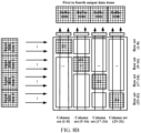
- FIG. 3 is a schematic diagram of a specific process of step S230 of the method 200 shown in FIG. 2 .
- FIG. 4A and FIG. 4B show a specific example of the method 200 shown in FIG. 2 .
- FIG. 3 to FIG. 4B correspond to a case that the input splice quantity is equal to 1 and the output splice quantity is greater than 1.
- step S230 of the method may be further implemented as including the following steps.
- step S310 a calculation parameter is set for each calculation unit in the systolic array.
- setting a calculation parameter for each calculation unit may include: before a calculation process for each input data item is performed, prestoring a required calculation parameter at each calculation unit; or in a calculation process for each input data item, sequentially providing a calculation parameter to each calculation unit in a systolic manner based on a clock used in a transfer process of the input data item, to perform calculation at each calculation unit.
- the systolic array may be used for calculation at a convolutional layer in a CNN model. Therefore, the calculation unit may include a calculation parameter such as a convolution kernel, so that the convolution kernel (for example, the 3 ⁇ 3 weight matrix described above) at the calculation unit can be set. In this embodiment, the calculation parameter of each calculation unit is determined with respect to each input data item. This is described in subsequent steps.
- a calculation parameter such as a convolution kernel
- step S320 input data items having the output splice quantity is used as a group of input data items, different output data items associated with different input data items in the group of input data items correspond to different column sets in the systolic array, and wherein different output data items correspond to different buffer zones of the output buffer. Any two buffer zones are not overlapped.
- the first input depth and the first output depth of the systolic array are both 32, and the second input depth and the second output depth of the shallow depth model are 32 and 8 respectively. Therefore, it can be determined that the input splice quantity is 1 and the output splice quantity is 4.
- four input data items (a depth of each input data item being 32) are generated as a group of input data items to be inputted to the input buffer at different times (sequentially) and then provided to each row of the systolic array.
- An output data item (that is, data calculated by using the systolic array) corresponding to the first input data item may be outputted from the 1st to the 8th columns of the systolic array (that is, corresponding to the 1 st to the 8th columns) and buffered to the first buffer zone of the output buffer
- an output data item corresponding to the second input data item may be outputted from the 9th to the 16th columns of the systolic array (that is, corresponding to the 9th to the 16th columns) and buffered to the second buffer zone of the output buffer
- an output data item corresponding to the third input data item may be outputted from the 17th to the 24th columns of the systolic array (that is, corresponding to the 17th to the 24th columns) and buffered to the third buffer zone of the output buffer
- an output data item corresponding to the fourth input data item may be outputted from the 25th to the 32nd columns of the systolic array (that is,
- the output buffer may include a plurality of output sub-buffers, and a quantity of output sub-buffers may be the same as a quantity of columns of the systolic array. Therefore, output data outputted by the last calculation unit in each column in each column set of the systolic array is buffered to a plurality of output sub-buffers whose quantity is equal to a quantity of columns in the column set, and the plurality of sub-buffers correspond to a buffer zone of the foregoing output buffer.
- step S330 the input buffer sequentially provides the group of input data items to the systolic array, wherein when the systolic array receives one input data item in the group of input data, the systolic array processes the one input data item according to a calculation parameter in a calculation unit corresponding to the one input data item to obtain an output data item corresponding to the input data item.
- the group of input data items includes four input data items (a depth of each input data item being 32, and a depth of a corresponding output data item being 8).
- the input buffer provides the input data item to the systolic array (a plurality of pieces of (multi-channel) input data of the input data item are inputted, in a systolic manner according to a specific time sequence, to respective rows in the systolic array).
- the systolic array outputs an output data item corresponding to the respective input data item.
- another input data item is inputted to the input buffer.
- step S340 for each input data item in the group of input data item, an output data item corresponding to the respective input data item is outputted to a buffer zone corresponding to the output data item.
- the input buffer inputs an input data item (for example, a depth is 32) to the systolic array in each calculation process, that is, for example, 32 pieces of input data of the input data item are inputted to 32 rows of the systolic array according to a specific time sequence, each calculation unit in each row performs calculation according to a piece of input data inputted to the row and a calculation parameter, and accumulation is performed with a calculation result of a calculation unit in a previous row of the same column.
- a depth of the output data item corresponding to the input data item is small (for example, a depth of an output data item shown in FIG. 4A is 8).
- the output data item corresponding to the input data item only needs to be outputted from some columns (for example, eight columns).
- calculation parameters related to the input data item need to be set at calculation units at intersection points between the columns (for example, eight columns) and rows (for example, 32 rows) of the systolic array that correspond to the depth of the input data item.
- a calculation parameter is prestored at each calculation unit or provided to each calculation unit in a systolic manner according to a time sequence in a calculation process.
- a calculation parameter can be provided for current calculation without affecting a previous calculation result of other input data item. This is not limited in the present disclosure.
- calculation parameters related to the respective input data item also need to be set at calculation units at intersection points between a column set (eight columns) corresponding to the respective input data item and rows (for example, 32 rows) of the systolic array that correspond to a depth of the respective input data item.
- calculation parameters need to be set at some specific calculation units.
- the specific calculation units are calculation units at intersection points between the 1st to the 8th columns and the 1st to the 32nd rows.
- a calculation parameter may be set at each calculation unit in the calculation unit array. For example, in FIG.
- calculation parameters required for calculation of the first input data item are set at calculation units at intersection points between the 1 st to the 8th columns and the 1st to the 32nd rows (a first zone Z1)
- calculation parameters required for calculation of the second input data item are set at calculation units at intersection points between the 9th to the 16th columns and the 1st to the 32nd rows (a second zone Z2)
- calculation parameters required for calculation of the third input data item are set at calculation units at intersection points between the 17th to the 24th columns and the 1st to the 32nd rows (a third zone Z3)
- calculation parameters required for calculation of the fourth input data item are set at calculation units at intersection points between the 25th to the 32nd columns and the 1st to the 32nd rows (a fourth zone Z4).
- this problem can be resolved by using following method: During calculation of each input data item, writing to a buffer zone that corresponds to an output data item corresponding to input data item other than the input data on which calculation is being performed in the group is prohibited. For example, output from an output port of the systolic array may be prohibited by using a controller (for example, an output enabling signal is made to be invalid), or writing to some zones of the output buffer may be prohibited by using the controller (for example, write enabling signals that correspond to write channels corresponding to the zones of the output buffer are made to be invalid).
- step S3 50 for the group of input data items, output data items with the output splice quantity in buffer zones of the output buffer is outputted in parallel s by the output buffer.
- four output data items corresponding to four input data items are respectively stored to four buffer zones of the output buffer (each buffer zone including eight output sub-buffers), and the four output data items are transferred from the output buffer to another apparatus (for example, a memory or the input buffer).
- a premise is that there are a plurality of input data items, so that there may be a plurality of output data items for outputting.
- the plurality of input data items may be divided into at least one group, each group of input data items includes input data items of the output splice quantity, and remaining input data items may be combined with input data items whose value is 0 into a group of input data items.
- the 10 input data items may be divided into three groups to perform the method described with reference to FIG. 3 to FIG. 4A , and one of the three groups of input data items includes two input data items whose values are 0.
- the image feature map tensor may be tiled in an H direction and a W direction to obtain a plurality of input data items, as shown in FIG. 4B .
- a value of a depth C of the tensor is equal to the second input depth (denoted as Ds), the second input depth being also the first input depth in this example, each piece of input data (each data matrix) included in each input data item can be exactly inputted to each row of the systolic array.
- each input data item needs to be further segmented into a plurality of segments of the input data item according to Ds in a C direction.
- a plurality of rounds of operations may be performed for the segmented input data item, and a subsequent processing unit may obtain, from the output buffer, values of a plurality of output data items corresponding to the plurality of segments of input data item obtained by segmenting the input data item, and then perform summation on the plurality of pieces of output data item to obtain a value of output data item corresponding to the input data item.
- each image feature map tensor may serve as a input data item.
- each tensor serving as each input data item may be further segmented or supplemented according to a magnitude relationship between a value of a depth C of the tensor and the second input depth (denoted as Ds), so that a depth of each input data item is Ds.
- a plurality of input data items corresponding to the plurality of tensors may be divided into at least one group of input data items (each group including input data items of the output splice quantity). For each group of input data items, calculation may be performed on the input data items of the respective group according to the method described with reference to FIG. 3 .
- obtaining a plurality of input data items may still be similar to that described herein.
- a piece of initial input data obtained is tiled in a horizontal direction and a vertical direction and possibly segmented in a depth direction, or each piece of data of initial input data obtained serves as a input data item. Therefore, this is not repeatedly described below.
- FIG. 5 is a schematic diagram of a specific process of step S230 of the method 200 shown in FIG. 2 .
- FIG. 6 shows a specific example.
- step S230 of the method 200 may further include the following steps.
- step 510 the input data items having the input splice quantity is used as a group of input data items, different input data items in the group corresponding to different row sets in the systolic array, and output data items associated with different input data items in the group corresponding to all columns in the systolic array.
- an output data item corresponding to each input data item is outputted from all columns of the systolic array to the output buffer.
- an output data item corresponding to each input data item is output to an entire buffer zone of the output buffer, and the output buffer buffers an output data item corresponding to a next input data item only after the current output data item in the output buffer is fetched.
- an output data item obtained for each input data item may be arranged in a depth-continuous manner in the output buffer.
- an output data item corresponding to the first input data item may occupy a buffer zone indicated by addresses 0 to 7 in the output buffer
- an output data item corresponding to the second input data item may occupy a buffer zone indicated by addresses 8 to 15 in the output buffer, and so on.
- the first input depth and the first output depth of the systolic array are both 32, and the second input depth and the second output depth of the shallow depth model are 8 and 32 respectively. Therefore, it can be determined that the input splice quantity is 4 and the output splice quantity is 1.
- four input data items (a depth of each input data item being 8) are generated as a group of input data items to be inputted to the input buffer and then provided to different row sets of the systolic matrix in parallel.
- the input buffer provides the first input data item to the 1st to the 8th rows of the systolic array (that is, corresponding to a row set including the 1st to the 8th rows), the input buffer provides the second input data item to the 9th to the 16th rows of the systolic array (that is, corresponding to a row set including the 9th to the 16th rows), the input buffer provides the third input data item to the 17th to the 24th rows of the systolic array (that is, corresponding to a row set including the 17th to the 24th rows), and the input buffer provides the fourth input data item to the 25th to the 32nd rows of the systolic array (that is, corresponding to a row set including the 25th to the 32nd rows).
- an output data item (that is, data calculated by the systolic array) corresponding to each of the four input data items may be outputted from the 1st to the 32nd columns of the systolic array and buffered to the entire buffer zone or at least some buffer zones of output buffer (according to the storage space of the output buffer).
- the output buffer may include a plurality of output sub-buffers. Therefore, an output data item outputted by the last calculation unit in each column of the systolic array is buffered to the plurality of output sub-buffers, and the plurality of sub-buffers correspond to the entire buffer zone or at least some buffer zones of the output buffer (according to the storage space of the output buffer).
- step S520 the input buffer provides the group of input data items to the calculation unit array in parallel.
- step S530 calculation is sequentially performed on each input data item in the group of input data items, and while performing calculation on each input data item, a calculation parameter of a calculation unit corresponding to the each input data item is set to a valid value, and calculation parameters of calculation units other than the calculation unit corresponding to the input data item on which calculation is being performed is set to 0.
- a manner of setting a calculation parameter at a calculation unit may include prestoring a calculation parameter at each corresponding calculation unit or providing a calculation parameter to each calculation unit in a systolic manner according to a time sequence.
- the systolic array accumulates calculation results of calculation units in the same column in a column direction and then performs output. Therefore, for the group of input data item (a depth being 8) provided to the systolic array in parallel, in a calculation process for each input data item, values of calculation parameters of calculation units in rows other than a row set corresponding to the input data on which calculation is being performed needs to be set to 0, so that only calculation results of the input data at calculation units in the corresponding row set are valid values, and calculation results at other calculation units are all 0.
- calculation results in the same column only calculation results of calculation units in the column and a corresponding row set are superimposed, thereby avoiding incorrectly superposing calculation results for different input data items in the same column (for example, calculation units in each column may perform calculation for four input data items in one calculation process, and a result of the calculation is incorrect). Based on this, calculation may be performed only for one input data item each time the group of input data items is inputted. For example, in FIG. 6 , first, calculation parameters of calculation units in the 1st to the 8th rows are set to valid values, and values of other calculation units are set to 0. Then the group of input data items is inputted in parallel for the first time.
- an calculated output data item (a depth being 32) corresponding to the first input data item (a depth being 8) is outputted in all columns of the systolic array.
- calculation parameters of calculation units in the 9th to the 16th rows are set to valid values, and values of other calculation units are set to 0.
- the group of input data items is inputted in parallel for the second time.
- an calculated output data item (a depth being 32) corresponding to the second input data item (a depth being 8) is outputted in all columns of the systolic array.
- FIG. 6 shows only a case of two input data items. Similar operations are performed for other input data items until all output data items corresponding to all input data items in the group of input data items have been outputted.
- the group of input data items (four input data items) is inputted to the input buffer (at the same time or different times), that is, the group of input data items is all buffered in the input buffer, and the input buffer may provide the group of input data items to the systolic array in parallel according to a predetermined time sequence (controlled by the controller and based on the operating principle of the systolic array).
- the first input data item is provided to the 1st to the 8th rows of the systolic array
- the second input data item is provided to the 9th to the 15th rows of the systolic array
- the third input data item is provided to the 16th to the 24th of the systolic array
- the fourth input data item is provided to the 25th to the 32nd rows of the systolic array.
- step S540 output data items corresponding to respective input data items are sequentially outputted to the output buffer.
- an output data item corresponding to the first input data item is outputted to a buffer zone of the output buffer, and at least after the output buffer is free again (that is, the output data item buffered in the output buffer is fetched) or when remaining storage space is sufficient for buffering an output data item corresponding to a next input data item, an output data item corresponding to the second input data item is outputted to the entire buffer zone or at least some buffer zones of the output buffer (according to the storage space of the output buffer).
- a calculation parameter used for calculation of the first input data item is set at each calculation unit (calculation parameters of calculation units in the 1st to the 8th rows are valid values, and calculation parameters of calculation units in remaining rows are 0), and in this case, calculation may be performed on the first input data item to obtain output data item corresponding to the first input data item.
- a calculation parameter used for calculation of the second input data item is set at each calculation unit (calculation parameters of calculation units in the 9th to the 16th rows are valid values, and calculation parameters of calculation units in remaining rows are 0), and then calculation is performed on the second input data item to obtain an output data item corresponding to the second input data item, and so on. Therefore, an order for performing the steps may be flexibly adjusted according to principles of technical solutions of the present disclosure.
- a group of input data items (input data items with the input splice quantity) is buffered in the input buffer and provided to the systolic array in parallel. Because the input buffer provides the same input to the systolic array for calculation of each input data item, the input data items needs to be transferred only once (for example, from another memory to the input buffer), thereby improving transfer efficiency of the input data items.
- a plurality of processes of transferring to the input buffer are required for the plurality of input data items (in this case, data of a channel corresponding to an insufficient depth of each input data item relative to the first input depth of the systolic array is supplemented with 0s).
- a process of loading a calculation parameter to a calculation unit may be performed only once. With the foregoing data processing method, only one process of transferring to the input buffer is required.
- FIG. 7 is a schematic diagram of an example process of steps of the method shown in FIG. 2 .
- FIG. 8A and FIG. 8B show more details about the data processing method of FIG. 7 in a case that the input splice quantity is equal to the output splice quantity.
- FIG. 9A to FIG. 9D show more details about the data processing method of FIG. 7 in a case that the input splice quantity is greater than the output splice quantity.
- FIG. 10A to FIG. 10D show more details about the data processing method of FIG. 7 in a case that the input splice quantity is less than the output splice quantity.
- step S230 of the data processing method 200 further includes the following steps.
- a comprehensive splice quantity is determined based on the input splice quantity and the output splice quantity.
- the comprehensive splice quantity is one of the input splice quantity and the output splice quantity.
- the comprehensive splice quantity may be a larger or smaller one of the input splice quantity and the output splice quantity; or in a case that the input splice quantity is equal to the output splice quantity, the comprehensive splice quantity is equal to the input splice quantity or the output splice quantity.
- step S720 input data items with the comprehensive splice quantity is used as a group of input data items.
- step S730 the group of input data items is divided into at least one subgroup based on the input splice quantity and the output splice quantity, wherein input data items in each subgroup correspond to row sets with the input splice quantity in the systolic array, and different output data corresponding to different input data items in the subgroup correspond to different column sets in the systolic array, and correspond to different buffer zones of the output buffer.
- a quantity of subgroups may be 1 or an integer greater than 1.
- Each subgroup may include one or more input data items.
- the first input depth and the first output depth of the systolic array are both 32, and the second input depth and the second output depth of the shallow depth model are 16 and 8 respectively. Therefore, it can be determined that the input splice quantity is 2, the output splice quantity is 4, and the comprehensive splice quantity is 4.
- the group of input data items includes four input data items. However, because the input splice quantity is 2, only two input data items (a depth being 16) can be provided to the systolic array at a time. Therefore, the four input data items are divided into two subgroups, one subgroup includes two input data items, and one subgroup of input data items is provided to the systolic array at a time.
- FIG. 8A and FIG. 8B show more details about the data processing method of FIG. 7 in a case that the input splice quantity is equal to the output splice quantity.
- the method of FIG. 7 may further include the following steps.
- the input splice quantity and the output splice quantity are equal (being 4 in the figures). In this case, it can be considered that there is only one subgroup, and each subgroup includes input data items of the input splice quantity (the output splice quantity).
- step S810 for a subgroup in the group of input data items, the input buffer provides input data items in the subgroup to the systolic array in parallel.
- each subgroup of input data items corresponds to row sets of the input splice quantity in the calculation unit array
- different output data items corresponding to different input data items in the group correspond to different column sets in the calculation unit array, and correspond to different buffer zones of the output buffer.
- the first input depth and the first output depth of the systolic array are both 32, and the second input depth and the second output depth of the shallow depth model are both 8.
- the input splice quantity is 4
- the output splice quantity is also 4.
- four input data items are used as a group of input data items to be inputted to the input buffer and then provided to different row sets of the systolic matrix in parallel, and output data items corresponding to input data items in the group are also outputted from different column sets of the systolic array.
- the input buffer provides the first input data item to the 1st to the 8th rows of the systolic array (that is, corresponding to a row set including the 1st to the 8th rows), and an output data item corresponding to the first input data item is outputted from the 1st to the 8th columns of the systolic array;
- the input buffer provides the second input data item to the 9th to the 16th rows of the systolic array (that is, corresponding to a row set including the 9th to the 16th rows), and an output data item corresponding to the second input data item is outputted from the 9th to the 16th columns of the systolic array;
- the input buffer provides the third input data item to the 17th to the 24th rows of the systolic array (that is, corresponding to a row set including the 17th to the 24th rows), and an output data item corresponding to the third input data item is outputted from the 17th to the 24th columns of the systolic
- the row sets corresponding to the four input data items included in the subgroup and the column sets corresponding to the four corresponding output data items may be expressed as follows: a first zone Z1 (1-8, 1-8); a second zone Z2 (9-16, 9-16); a third zone Z3 (17-24, 17-24); and a fourth zone Z4 (25-32, 25-32).
- the output buffer may include a plurality of output sub-buffers. Therefore, an output data item outputted by the last calculation unit in each column of the systolic array is buffered to the plurality of output sub-buffers, and the plurality of sub-buffers correspond to the entire buffer zone or at least some buffer zones of the output buffer (according to the storage space of the output buffer).
- step S820 for calculation of the subgroup, a calculation parameter of a calculation unit corresponding to each input data item in the subgroup of input data is set to a valid value, and calculation parameters of remaining calculation units other than the calculation unit corresponding to the input data on which calculation is being performed is set to 0.
- the systolic array accumulates calculation results of calculation units in the same column in a column direction and then performs output. Therefore, for each input data item in each subgroup of input data items provided to the systolic array in parallel, in a calculation process for one input data item, a calculation parameter at a calculation unit irrelevant with calculation of the one input data item needs to be set to 0 to ensure accuracy and a correspondence of an output data item.
- a calculation parameter at a calculation unit irrelevant with calculation of the one input data item needs to be set to 0 to ensure accuracy and a correspondence of an output data item.
- FIG. 8B four zones (Z1 to Z4) are indicated by shaded parts in FIG. 8B , calculation parameters are respectively set for calculation units used for performing calculation on corresponding input data items in the shaded areas, and calculation parameters of other calculation units (for example, areas in blank blocks) in each column are set to 0.
- step S830 for each input data item in the subgroup, an output data item corresponding to a respective input data item is outputted to a buffer zone corresponding to the output data item, that is, output data items corresponding to the subgroup of input data items are buffered in the output buffer.
- output data items (four output data items) corresponding to respective input data items in the subgroup of input data items are buffered in the output buffer. Therefore, the four output data items can be fetched from the output buffer at a time.
- the input splice quantity is greater than 1
- the output splice quantity is greater than 1
- the output splice quantity is greater than or less than the input splice quantity.
- FIG. 9A shows more details about the data processing method of FIG. 7 in a case that the output splice quantity is an integer multiple, which is greater than 1, of the input splice quantity.
- the comprehensive splice quantity is the output splice quantity, and each subgroup of input data includes input data of the input splice quantity.
- the data processing method described with reference to FIG. 7 may further include the following steps.
- step S910 for calculation of input data items in each subgroup, the input buffer provides the input data items in the subgroup to the systolic array in parallel.
- the input splice quantity may be 2
- the output splice quantity is 4
- the comprehensive splice quantity is 4.
- a group of generated input data items (four input data items) is divided into two subgroups, and each subgroup includes two input data items.
- Each subgroup of input data items (including two input data items) is sequentially inputted to the input buffer, and each subgroup of input data is provided to the systolic array in parallel.
- step S920 for calculation of input data items in each subgroup, a calculation parameter of a calculation unit corresponding to each input data item in the subgroup is set to a valid value, and calculation parameters of remaining calculation units in the systolic array other than the calculation units corresponding to the input data items in the each subgroup are set to 0.
- row sets corresponding to the first subgroup (including the first input data item and the second input data item) and column sets corresponding to corresponding output data items are respectively expressed as follows: a first zone Z1 (1-16, 1-8) and a second zone Z2 (17-32, 9-16). Before calculation is performed on the first subgroup, calculation parameters need to be set for calculation units in the row sets and the column sets.
- Row sets corresponding to the second subgroup (including the third input data item and the fourth input data item) and column sets corresponding to corresponding output data items are respectively expressed as follows: a third zone Z3 (1-16, 17-24) and a fourth zone Z4 (17-32, 25-32).
- calculation parameters need to be set for calculation units in the row sets and the column sets. Because zones covered by the row sets and the column sets do not overlap, a simple method is that calculation parameters of calculation units required for calculation of the two subgroups may be set together.
- writing is performed only to buffer zones corresponding to output data items corresponding to a subgroup on which calculation of input data items is being performed, and writing is prohibited to buffer zones that correspond to output data items corresponding to subgroups other than the subgroup on which calculation of input data items is being performed.
- step S930 output data items corresponding to the group of input data items are outputted to the output buffer.
- four output data items corresponding to the two subgroups of input data items are outputted from the 1st to the 32nd columns of the systolic array (two output data items corresponding to the first subgroup being outputted from the 1st to the 16th columns first, and then other two output data items corresponding to the second subgroup being outputted from the 17th to the 32nd columns), that is, outputted to the entire buffer zone or at least some buffer zones of the output buffer, so that an external apparatus or the input buffer can fetch the output data items from the output buffer in parallel.
- FIG. 9C shows more details about the data processing method of FIG. 7 in a case that the output splice quantity is greater than the input splice quantity but is not an integer multiple of the input splice quantity.
- the comprehensive splice quantity is the input splice quantity
- a quantity of subgroups is 1, that is, a group of generated input data includes only one subgroup.
- step S910' the input buffer provides the group of input data items to the systolic array in parallel.
- the input splice quantity may be 3, the output splice quantity is 4, and the comprehensive splice quantity is 3.
- the group of generated input data items (three input data items) is inputted to the input buffer in parallel, so as to be provided to the systolic array in parallel.
- step S920' for calculation of the group of input data items, a calculation parameter of a calculation unit corresponding to each input data item in the group of input data items is set to a valid value, and calculation parameters of remaining calculation units in the systolic array other than calculation units corresponding to the input data items in the group are set to 0.
- row sets corresponding to the group of input data items (including the first to the third input data items) and column sets corresponding to corresponding output data items are respectively expressed as follows: (1-12, 1-16), (13-24, 17-32), and (25-36, 33-48).
- Calculation parameters of calculation units in the row sets and the column sets may be set to valid values, and calculation parameters of remaining calculation units (including calculation units in the 49th to the 64th columns) are set to 0.
- calculation parameters of calculation units required for calculation of the two subgroups of input data items may be set together.
- step S930' output data items corresponding to the group of input data items are outputted to the output buffer. Values of at least a part of the entire buffer zone of the output buffer are 0.
- three output data items corresponding to the group of input data items are outputted from the 1 st to the 48th columns of the systolic array, and calculation units in the 49th to the 64th columns also output calculated 0s. That is, buffer zones corresponding to the 1st to the 48th columns in the output buffer stores valid data, and a remaining buffer zone stores 0s, so that the output data items and 0s can be fetched from the output buffer in parallel.
- the following mainly describes a case that the input splice quantity is greater than 1, the output splice quantity is greater than 1, and the input splice quantity is greater than the output splice quantity.
- the input splice quantity is an integer multiple, which is greater than 1, of the output splice quantity.
- FIG. 10A and FIG. 10B show more details about the data processing method of FIG. 7 in a case that the input splice quantity is an integer multiple, which is greater than 1, of the output splice quantity.
- the comprehensive splice quantity is the input splice quantity, and each subgroup of input data items includes input data items with the output splice quantity.
- the output splice quantity may be 2, the input splice quantity is 4, and the comprehensive splice quantity is 4.
- Each subgroup of input data items includes two input data items.
- the method of FIG. 7 may further include the following steps.
- step S 1010 the input buffer provides input data items in each subgroup to the calculation unit array in parallel.
- step S 1020 for calculation of each subgroup, a calculation parameter of a calculation unit corresponding to each input data item in the subgroup is set to a valid value, and calculation parameters of remaining calculation units other than the calculation unit corresponding to the input data items in the each subgroup of input data items in the systolic array are set to 0.
- row sets corresponding to the first subgroup (including the first input data item and the second input data item) and column sets corresponding to corresponding output data are respectively expressed as follows: a first zone Z1 (1-8, 1-16), a second zone Z2 (9-16, 17-32), a third zone Z3 (17-24, 1-16), and a fourth zone Z4 (25-32, 17-32).
- Calculation parameters of calculation units that are in the first zone Z1 (1-8, 1-16) and that are used for calculation of the first subgroup of input data items are set to valid values
- calculation parameters of calculation units that are in the second zone Z2 (9-16, 17-32) and that are used for calculation of the first subgroup of input data items are set to valid values
- calculation parameters of remaining calculation units are 0.
- two subgroups of input data items are inputted in parallel.
- calculation parameters of calculation units in the third zone Z3 (17-24, 1-16) are set to valid values
- calculation parameters of calculation units in the fourth zone Z4 (25-32, 17-32) are set to valid values
- calculation parameters of remaining calculation units are 0.
- step S1030 output data items corresponding to each subgroup are sequentially outputted to the output buffer.
- output data items corresponding to the first input data item and the second input data item included in the first subgroup of input data items are outputted to the output buffer from all columns of the systolic array.
- a calculation result of the subsequent second subgroup of input data items is outputted to the output buffer.
- the input splice quantity is greater than the output splice quantity but is not an integer multiple of the output splice quantity.
- FIG. 10C and FIG. 10D show more details about the data processing method of FIG. 7 in a case that the input splice quantity is greater than the output splice quantity but is not an integer multiple of the output splice quantity.
- the comprehensive splice quantity is the output splice quantity
- a quantity of subgroups is 1, that is, a group of generated input data includes only one subgroup.
- the output splice quantity may be 3, the input splice quantity is 4, and the comprehensive splice quantity is 3.
- the group of input data and the subgroup of input data include three pieces of input data.
- the method of FIG. 7 may further include the following steps, as shown in FIG. 10C .
- step S1010' N input data items complemented with 0s are added to the group of input data items, a value of N being equal to the input splice quantity minus the output splice quantity.
- one input data item (a depth being 12) is added to match a quantity of rows of the systolic array.
- step S 1020' the input buffer provides the group of input data items to the systolic array in parallel.
- step S1030' before calculation is performed on the group of input data items, a calculation parameter of a calculation unit corresponding to each input data item in the group of input data items is set to a valid value, and calculation parameters of remaining calculation units in the systolic array other than the calculation units corresponding to the input data items in the group are set to 0.
- row sets corresponding to the group of input data items and column sets corresponding to corresponding output data items are respectively expressed as follows: a first zone Z1 (1-12, 1-12), a second zone Z2 (13-24, 13-24), and a third zone Z3 (25-36, 25-36).
- Calculation parameters need to be set for calculation units that are in the row sets and the column sets and that are used for calculation of the group.
- Calculation parameters of calculation units in zones of the row sets and the column sets are set to valid values, and calculation parameters of remaining calculation units (including calculation units in the 37th to the 48th rows corresponding to added 0 input data) are set to 0.
- step S1040' output data items corresponding to respective input data items in the group is outputted to the output buffer.
- output data items corresponding to three input data items are all buffered to the entire buffer zone or at least some buffer zones of the output buffer, so as to be outputted from the output buffer in parallel.
- a group of input data items (input data items with the output splice quantity) can be buffered to the input buffer and provided to the systolic array in parallel, and a plurality of output data items that correspond to the group of input data items and that are outputted by the systolic array may be buffered to the output buffer and outputted from the output buffer in parallel, so that transfer efficiency of the input data items and the output data items can be improved.
- the systolic array may perform calculation for at least two input data items in the group of input data items in one calculation process. Compared to the related technology described with reference to FIG. 1 that calculation is performed only for one input data item in one calculation process, this improves calculation efficiency and utilization efficiency of calculation units in the systolic array.
- a calculation apparatus is further provided.
- An architecture of the calculation apparatus is basically the same as that of the calculation apparatus 100 described with reference to FIG. 1 .
- the calculation apparatus 100 includes a controller 101, a data fetcher 102, a systolic array 103, an input buffer 104, and an output buffer 105.
- the controller 101 obtains a first input depth and a first output depth of the systolic array 103, and obtains a second input depth and a second output depth of a shallow depth model. Then the controller 101 determines an input splice quantity for the systolic array based on the second input depth and the first input depth, and determines an output splice quantity for the systolic array based on the second output depth and the first output depth, the input splice quantity and/or the output splice quantity being an integer greater than 1.
- the controller 101 controls the data fetcher 102 to generate a group of input data items with the input splice quantity, each input data items of the group of input data items having the second input depth, input the group of input data items to an input buffer 104 of the systolic array 103, and controls the systolic array 103 to process the group of input data items in the input buffer 104 to generate a group of output data items corresponding to the group of input data items, each output data item of the group of output data items having the second output depth; and for a case that a quantity of output data items received by the output buffer 105 of the systolic array 103 from the systolic array 103 reaches the output splice quantity, controls the output buffer 105 of the systolic array 103 to output the output data items having a quantity matching the output splice quantity.
- the systolic array 103 may be a calculation unit array, and a quantity of rows and a quantity of columns of the calculation unit array may correspond to (being equal to or greater than) the first input depth and the first output depth respectively.
- a depth of the input buffer 104 corresponds to the first input depth
- a depth of the output buffer 105 corresponds to (being equal to or greater than) the first output depth.
- the controller 101 controls setting of a calculation parameter (for example, a convolution kernel in a CNN model) for each calculation unit in the calculation unit array, and controls the data fetcher 102 to use input data items with the output splice quantity as a group of input data items, different output data items that corresponds to different input data items in the group of input data items correspond to different column sets in the calculation unit array 103, and correspond to different buffer zones of the output buffer 105; controls the data fetcher 102 to sequentially input the group of input data items to the input buffer; and controls the input buffer 104 to sequentially provide the group of input data items to the calculation unit array, so that each time the systolic array receives one input data item in the group of input data items, the systolic array processes the input data item according to a calculation parameter in a calculation unit corresponding to the input data item to obtain an output data item
- a calculation parameter for example, a convolution kernel in a CNN model
- the controller 101 controls the calculation unit array to output, to a corresponding buffer zone in the output buffer, output data items corresponding to the input data items. Then, for the group of input data items, the controller 101 controls the output buffer 105 to output, in parallel, output data items with the output splice quantity in zones of the output buffer 105.
- the controller 101 may: control the data fetcher 102 to use the input data items with the input splice quantity as a group of input data items, different input data items in the group of input data items corresponding to different row sets in the calculation unit array, and output data items that corresponds to different input data items in the group o correspond to all columns in the calculation unit array, and correspond to an entire buffer zone or at least some buffer zones of the output buffer; control the data fetcher 102 to input the group of input data items to the input buffer 104; and control sequential setting, in each calculation unit, of a calculation parameter of each calculation unit required for performing calculation on each input data item in the group of input data items.
- the controller 101 controls the systolic array to sequentially perform calculation on each input data item in the group of input data items, and in a process of performing calculation on each input data item, set a calculation parameter of a calculation unit corresponding to the each input data item to a valid value, and set calculation parameters of calculation units other than the calculation unit corresponding to the each input data item on which calculation is being performed to 0. For example, for each input data item, calculation parameters of calculation units in a row set corresponding to the input data items are valid values, and calculation parameters of remaining calculation units are 0.
- the controller 101 controls the systolic array to sequentially output, to the output buffer, output data corresponding to each input data item.
- the controller 101 controls the input buffer to provide the input data items with the input splice quantity to the calculation unit array 103 in parallel; and for the group of input data items, controls sequential output of output data items corresponding to respective input data items to the entire buffer zone or at least some buffer zones of the output buffer (according to storage space of the output buffer), to perform sequential output or output in parallel using the output buffer (according to the storage space of the output buffer).
- the controller 101 may: determine a comprehensive splice quantity based on the input splice quantity and the output splice quantity; control the data fetcher 102 to use input data items with the comprehensive splice quantity as a group of input data items; and controls the data fetcher 102 to divide the group of input data items into at least one subgroup based on the input splice quantity and the output splice quantity, input data items in each subgroup corresponding to different row sets with the input splice quantity in the calculation unit array, and output data items that correspond to different input data items in the subgroup correspond to different column sets in the calculation unit array, and corresponding to different buffer zones of the output buffer 105.
- the input splice quantity is greater than 1, the output splice quantity is greater than 1, and the input splice quantity is equal to the output splice quantity.
- the comprehensive splice quantity is the input splice quantity or the output splice quantity, a quantity of subgroups is 1, and the controller 101 may further: for a subgroup in the group of input data items, control the input buffer 104 to provide input data items in the subgroup to the calculation unit array 103 in parallel; for calculation of the subgroup, control setting of a calculation parameter of a calculation unit corresponding to each input data item in the subgroup of input data to a valid value, and setting of calculation parameters of remaining calculation units other than the calculation unit corresponding to the input data item on which calculation is being performed to 0; and control the systolic array to output, to the output buffer 105, output data items corresponding to input data items in the subgroup, and control the output buffer 105 to output the output data items in parallel.
- the input splice quantity is an integer multiple, which is greater than 1, of the output splice quantity.
- the comprehensive splice quantity is the input splice quantity
- a quantity of input data items in each subgroup included in the group of input data item is the output splice quantity
- the controller 101 may further: control the data fetcher 102 to input, to the input buffer 104, input data items with the comprehensive splice quantity, and control the input buffer 104 to provide input data items in each subgroup to the calculation unit array 103 in parallel; for calculation of each subgroup, control setting of a calculation parameter of a calculation unit corresponding to each input data item in the subgroup to a valid value, and setting of calculation parameters of remaining calculation units other than the calculation unit corresponding to the input data items in the subgroup of input data items to 0; and for the group of input data items including the input data items with the comprehensive splice quantity, control the calculation unit array 103 to sequentially output, to the output buffer 105, output data items
- the input splice quantity is greater than the output splice quantity but is not an integer multiple of the output splice quantity.
- the comprehensive splice quantity is the output splice quantity, a quantity of subgroups is 1, and the controller 101 may further: control the data fetcher 102 to add N input data items complemented with 0s to the group of input data items, a value of N being equal to the input splice quantity minus the output splice quantity; control the data fetcher 102 to input, to the input buffer 104 in parallel, the group of input data items to which the N input data items are added, and control the input buffer to provide the group of input data items to the calculation unit array 103 in parallel; for calculation of the group of input data items, control setting of a calculation parameter of a calculation unit corresponding to each input data item in the group of input data items to a valid value, and setting of calculation parameters of remaining calculation units other than the calculation unit corresponding to the input data items in the group of input data items
- the output splice quantity is an integer multiple, which is greater than 1, of the input splice quantity.
- the comprehensive splice quantity is the output splice quantity
- each subgroup of input data includes input data of the input splice quantity
- the controller 101 may further: for calculation of input data in each subgroup, control the data fetcher 102 to sequentially input, to the input buffer 104 by subgroup, input data items with the comprehensive splice quantity, and control the input buffer 104 to provide the input data items in each subgroup to the calculation unit array in parallel; for calculation of each subgroup of input data items, control setting of a calculation parameter of a calculation unit corresponding to each input data item in the subgroup to a valid value, and setting of calculation parameters of remaining calculation units other than the calculation unit corresponding to the input data items in the subgroup to 0; and control the calculation unit array 103 to output, to the output buffer 105, output data items corresponding to the group of input data items (including all subgroups of input data
- the controller 101 may further: control the data fetcher 102 to input the group of input data items to the input buffer 104 in parallel, and control the input buffer 104 to provide the group of input data items to the calculation unit array in parallel; for calculation of the group of input data items, control setting of a calculation parameter of a calculation unit corresponding to each input data item in the group of input data items to a valid value, and setting of calculation parameters of remaining calculation units other than the calculation unit corresponding to the input data items in the group to 0; and control the calculation unit array 103 to output, to the output buffer 105, output data corresponding to the group of input data items, to perform output in parallel by using the output buffer, values of at least a part of an entire buffer zone being 0.
- a form of one or more controllers may include a calculation device capable of performing any of the foregoing operations described in this specification.
- a general purpose processor a DSP, an ASIC, an FPGA or another programmable logic device, a discrete gate or transistor logic, a discrete hardware component, or any combination thereof implements or performs the operations.
- the general purpose processor may be a microprocessor, a microcontroller, or the like.
- the operations described herein may be implemented in hardware, software executed by a processor, firmware, or any combination thereof. When implemented by using software executed by a controller in the form of processor, these operations can be stored in a computer-readable storage medium or can be encoded as one or more instructions or code in a computer-readable medium for transmission.
- an embodiment of the present disclosure also provides a computer-readable storage medium, storing an instruction or code, the instruction or code, when executed by a processor, implementing the foregoing operations performed by the controller.
- the computer-readable storage medium may be a memory including an instruction or code.
- the code or instruction set may be executed by a controller (processor) to implement all or some steps performed by the controller (including controlling components such as an input buffer and a DSP in a calculation unit) in the calculation apparatus.
- the computer-readable storage medium may be a ROM, a random access memory (RAM), a CD-ROM, a magnetic tape, a floppy disk, an optical data storage device, or the like.
- each box in the flowchart or the block diagram may represent a module, a program segment, or a part of code.
- the module, the program segment, or the part of code includes at least one executable instruction used for implementing specified logic functions.
- functions marked in boxes may alternatively occur in a sequence different from that marked in an accompanying drawing. For example, two boxes shown in succession may actually be performed basically in parallel, and sometimes the two boxes may be performed in a reverse sequence. This is determined by a related function.
- Each box in a block diagram and/or a flowchart and a combination of boxes in the block diagram and/or the flowchart may be implemented by using a dedicated hardware-based system configured to perform a specified function or operation, or may be implemented by using a combination of dedicated hardware and a computer instruction.
Landscapes
- Engineering & Computer Science (AREA)
- Theoretical Computer Science (AREA)
- Physics & Mathematics (AREA)
- Computer Hardware Design (AREA)
- General Physics & Mathematics (AREA)
- General Engineering & Computer Science (AREA)
- Software Systems (AREA)
- Computing Systems (AREA)
- Evolutionary Computation (AREA)
- Biophysics (AREA)
- Health & Medical Sciences (AREA)
- Biomedical Technology (AREA)
- Artificial Intelligence (AREA)
- Life Sciences & Earth Sciences (AREA)
- Computational Linguistics (AREA)
- Neurology (AREA)
- Data Mining & Analysis (AREA)
- Computer Vision & Pattern Recognition (AREA)
- Medical Informatics (AREA)
- Geometry (AREA)
- General Health & Medical Sciences (AREA)
- Molecular Biology (AREA)
- Mathematical Physics (AREA)
- Complex Calculations (AREA)
- Image Processing (AREA)
- Multi Processors (AREA)
Abstract
The present disclosure provides a systolic array-based data processing method, an apparatus, a medium, and a program product. Said method comprises: determining a standard input depth/standard output depth of a systolic array and an input depth and an output depth of a depth model, so as to determine the number of input splices and the number of output splices; splicing input data and corresponding output data according to the number of input splices and the number of output splices, so as to acquire the input data in batches and provide the input data in parallel to the systolic array; and caching, by means of an output cache, the multiple pieces of output data corresponding to the multiple pieces of input data, and then outputting same in batches. Thus, the migration efficiency of the input data and/or output data is improved, and the utilization efficiency of the systolic array can be further improved.
Description
- This application claims priority to
Chinese Patent Application No. 202110219814.4, entitled "CALCULATION OPTIMIZATION METHOD AND APPARATUS OF SHALLOW DEPTH MODEL BASED ON SYSTOLIC ARRAY" filed with the China National Intellectual Property Administration on February 26, 2021 - The present disclosure relates to the computer field, and more specifically, to a systolic array-based data processing method and apparatus, a medium, and a program product.
- In the data processing field, many data processing processes, such as a deep learning process, may be performed by using a convolutional neural network (CNN), and a large number of calculation steps need to be performed, most of which are multiply-accumulate operations.
- Currently, a systolic array structure has been used for implementing a large number of multiply-accumulate operation processes. The systolic array structure includes calculation units (denoted as PEs, each PE including a multiplier-accumulator or a similar calculation device, and/or a storage unit) disposed at nodes of each row and each column. An advantage lies in that an operand or an intermediate result participating in an internal operation can participate in a high-speed parallel pipeline manner, that is, simple and efficient systolic transfer can be implemented for each piece of input data (data inputted to each row) and a calculation result of each PE in the entire array, thereby improving data reuse, reducing off-chip data transfer, and reducing a bandwidth requirement. Therefore, one or more two-dimensional systolic arrays are widely used in artificial intelligence (AI) processors as a calculation core for multiply-accumulate operations, for example, a TPU.
- To resolve the foregoing problems, embodiments of the present disclosure provide a systolic array-based data processing method and apparatus, a medium, and a program product.
- According to an aspect of the present disclosure, a systolic array-based data processing method is provided, including: obtaining a first input depth of the systolic array and a first output depth of the systolic array, and obtaining a second input depth of a shallow depth model and a second output depth of the shallow depth model; determining an input splice quantity for the systolic array based on the second input depth and the first input depth, and determining an output splice quantity for the systolic array based on the second output depth and the first output depth; generating a group of input data items with the input splice quantity, each input data item of the group of input data items having the second input depth; inputting the group of input data items to an input buffer of the systolic array ; processing, by the systolic array, the group of input data items in the input buffer to generate a group of output data items corresponding to the group of input data items, each output data item of the group of output data items having the second output depth; and for a case that a quantity of output data items received by an output buffer of the systolic array from the systolic array reaches the output splice quantity, outputting the output data items having a quantity matching the output splice quantity in the output buffer.
- According to another aspect of the present disclosure, a calculation apparatus is provided, and the calculation apparatus may include: a controller, a data fetcher, a systolic array, an input buffer, and an output buffer; wherein the controller is configured to: obtain a first input depth of the systolic array and a first output depth of the systolic array, and obtain a second input depth of a shallow depth model and a second output depth of the shallow depth model; determine an input splice quantity for the systolic array based on the second input depth and the first input depth, and determine an output splice quantity for the systolic array based on the second output depth and the first output depth; generate a group of input data items with the input splice quantity, each input data item of the group of input data items having the second input depth; input the group of input data items to an input buffer of the systolic array; process, by the systolic array, the group of input data items in the input buffer to generate a group of output data items corresponding to the group of input data items, each output data item of the group of output data items having the second output depth; and for a case that a quantity of output data items received by an output buffer of the systolic array from the systolic array reaches the output splice quantity, output the output data items having a quantity matching the output splice quantity in the output buffer.
- According to still another aspect of the present disclosure, a computer-readable storage medium is further provided, storing an instruction or code, the instruction or code, when executed by a processor, implementing the foregoing operations performed by the controller in the calculation apparatus.
- According to still another aspect of the present disclosure, a computer program product is further provided, having an instruction or code, the data processing method above being implemented for a case that the instruction or the code is executed by a calculation apparatus.
- To describe the technical solutions of the embodiments of the present disclosure more clearly, the following briefly introduces the accompanying drawings required for describing the embodiments. The accompanying drawings described below are only some exemplary embodiments of this application.
-
FIG. 1 is a schematic structural diagram of a systolic array-based calculation apparatus according to an embodiment of the present disclosure. -
FIG. 2 is a schematic flowchart of a systolic array-baseddata processing method 200 according to an embodiment of the present disclosure. -
FIG. 3 is a schematic diagram of an example process of steps of the method shown inFIG. 2 . -
FIG. 4A andFIG. 4B show a specific example. -
FIG. 5 is a schematic diagram of an example process of steps of the method shown inFIG. 2 . -
FIG. 6 shows a specific example. -
FIG. 7 is a schematic diagram of an example process of steps of the method shown inFIG. 2 . -
FIG. 8A andFIG. 8B show a case of the process shown inFIG. 7 and a corresponding specific example. -
FIG. 9A to FIG. 9D show another case of the process shown inFIG. 7 and another corresponding specific example. -
FIG. 10A to FIG. 10D show still another case of the process shown inFIG. 7 and still another corresponding specific example. - To make the objectives, technical solutions, and advantages of the present disclosure more obvious, exemplary embodiments of the present disclosure are described in detail below with reference to the accompanying drawings. Apparently, the described embodiments are merely some but not all of the embodiments of this application. It is to be understood that, this application is not limited by the exemplary embodiments described herein.
- In this specification and the drawings, substantially the same or similar steps and elements are denoted by the same or similar reference numerals, and repeated descriptions of these steps and elements are omitted. In addition, in the description of the present disclosure, the terms "first", "second" and the like are used only to distinguish descriptions and are not to be construed as indicating or implying relative importance or sorting.
- Deep learning (also referred to as deep structured learning or hierarchical learning) is a part of a more extensive family of machine learning methods based on an artificial neural network. Learning may be supervised, semi-supervised, or unsupervised.
- As described above, data processing in deep learning may be performed, for example, by using a convolutional neural network (CNN). The convolutional neural network (CNN) mainly includes an input layer, a convolutional layer, an activation function, a pooling layer, a fully connected layer, and a loss function, and there may be a plurality of intermediate layers (for example, convolutional layers and pooling layers). A large number of multiply-accumulate operations of data are involved in calculation at the convolutional layer. Therefore, a systolic array structure may be used for implementing a calculation process at the convolutional layer. Although an example in which the systolic array structure is applied to the calculation at the convolutional layer is used in the context of the present disclosure for description, the systolic array structure may be alternatively applied to calculation of any matrix.
- Before embodiments of the present disclosure are described in detail, some terms used in this specification are briefly described.
- Shallow depth model: a lightweight model used in deep learning for generating output data based on input data, depths of the input data and the output data being generally small. A calculation process of the shallow depth model is implemented based on a systolic array described below.
- Systolic array: A systolic array has a plurality of calculation units arranged in rows and columns. A calculation unit includes a calculation element such as a multiply-accumulate unit (for example, implemented by a multiplier-accumulator), to perform matrix multiplication as a basic calculation unit of a neural network. The calculation units are connected to each other through wires. After necessary buffers are integrated in the calculation units, the buffers are connected to buffers outside the calculation units. A systolic matrix is named after a systolic function of a heart: Like blood flow, data is "pumped" by the calculation units.
-
FIG. 1 is a schematic structural diagram of a systolic array-based calculation apparatus 100 according to an embodiment of the present disclosure. - As shown in
FIG. 1 , the calculation apparatus 100 includes: acontroller 101, adata fetcher 102, asystolic array 103, aninput buffer 104, and anoutput buffer 105. - In this embodiment of the present disclosure, for ease of description, only one
controller 101 is shown inFIG. 1 , but a person skilled in the art is to understand that the controller may be a general term for a plurality of control modules that cooperate with each other to control all operations of the calculation apparatus 100. Thecontroller 101 herein may be one or more of a global controller for global control, various types of control logic or control circuits for controlling operations of the data fetcher, the input buffer, and the output buffer, and the like; or may be a combination of multiplier-accumulators in calculation units. For example, the global controller may be configured with, for example, instruction parsing and parameter configuration functions, to provide operating parameters for thedata fetcher 102, theinput buffer 104, theoutput buffer 105, and the like. Control logic corresponding to theinput buffer 104 may control transmission of buffered input data to thesystolic array 103. Control logic corresponding to the output buffer may control buffering of output data of thesystolic array 103 to the output buffer, and output the output data from the output buffer. - The
systolic array 103 may be a calculation unit array (also used interchangeably with the systolic array in the following descriptions), and may have a first input depth and a first output depth. A quantity of rows and a quantity of columns of the calculation unit array correspond to the first input depth and the first output depth respectively. In other words, the first input depth is the quantity of rows of the calculation unit array, and the first output depth is the quantity of columns of the calculation unit array. In some embodiments, the quantity of rows and the quantity of columns of the calculation unit array may be equal to the first input depth and the first output depth may respectively. In some other embodiments, the quantity of rows and the quantity of columns of the calculation unit array may be greater than the first input depth and the first output depth respectively, so that calculation units in some rows and columns serve as alternatives or redundancy. This is not limited in the present disclosure. In different cases, the first input depth and the first output depth of the calculation unit array may be different. For example, for different types of AI processors including calculation unit arrays, calculation unit arrays 16×32, 32×32, and the like may be selected. - The calculation unit array (systolic array) 103 may include at least one row of calculation units, each row of calculation units includes at least two
calculation units 103a, and twoadjacent calculation units 103a in each row of calculation units are connected. - The
input buffer 104 buffers at least one input data item that comes from thedata fetcher 102 and that requires calculation by the systolic array. An input data item may be one or more pieces of data. For example, an input to a shallow depth model (i.e., an input required to execute a shallow depth model one time) performed in thesystolic array 103 may be referred to as an input data item. A process of using one input by the shallow depth model to obtain an output may be considered as executing the shallow depth model once. Theinput buffer 104 may also buffer calculation parameters used for calculation. The calculation parameters may be provided by the data fetcher 102 directly to thesystolic array 103 or provided to thesystolic array 103 through theinput buffer 104. Each input data item may also have a depth (which may be considered as including one or more pieces of input data or single or multi-channel input data). The depth of the input data item represents a quantity of rows of calculation units to be required for the input data item. Since each piece of input data included in the input data item may only use a row of calculation units in thesystolic array 103, the quantity of all pieces of input data in one input data item is equal to the depth of one input data item. In addition, theinput buffer 104 may include a plurality (for example, equal to the quantity of rows of the systolic array) of input sub-buffers (not shown), and each input sub-buffer is configured to provide a piece of input data to calculation units in a row of the systolic array. For example, for a case that a depth of an input data item is m (m is an integer greater than or equal to 1), the input data item may be considered as including m pieces of input data or input data of m channels, and the m pieces of input data are buffered to the m input sub-buffers respectively according to an input format and a time sequence required for the systolic array, so that the m input sub-buffers input the m pieces of input data to m rows of the systolic array respectively according to the time sequence of the systolic array. - The controller 101 (for example, control logic corresponding to the input buffer 104) may control input of input data in the
input buffer 104 to acalculation unit 103a in a corresponding row, and acalculation unit 103a in each row transmits each piece of received input data in thecalculation unit 103a in the corresponding row. For example, for a case that acalculation unit 103a in the first column of the first row receives a piece of input data from the first input sub-buffer, the calculation unit transfers the input data to a calculation unit in the second column of the first row, and the input data is sequentially transferred in a systolic manner. A difference between times at whichfirst calculation units 103a in adjacent rows each receive a piece of input data in the input data item is one clock. - Each
calculation unit 103a in thesystolic array 103 is configured to calculate a piece of received input data and a corresponding calculation parameter (for example, a weight coefficient of a convolution kernel in a CNN model). For each column of thesystolic array 103, calculation results of allcalculation units 103a in the column are superposed (that is, accumulated for summation) (from bottom to top in the figure), and a piece of output data is obtained at thelast calculation unit 103a in each column (the mth row of each column), so that the piece of output data of the column is outputted to theoutput buffer 105. The calculation parameter may be updated as needed, provided that the calculation parameter can be used by a corresponding calculation unit for a case that each calculation unit of the systolic array performs a calculation task. For example, according to a setting manner of the systolic array, for calculation of each piece of input data, a calculation parameter at each calculation unit may be prestored on the calculation unit, or may be transferred to each calculation unit in a systolic manner during calculation according to a clock the same as that of systolic transfer of input data and according to a direction different from that of systolic transfer of input data (the directions being perpendicular). This is the same as a general principle of the systolic array. - Likewise, the
output buffer 105 may include a plurality of output sub-buffers, configured to buffer output data outputted by thelast calculation unit 103a in each column. The controller 101 (for example, the control logic corresponding to the output buffer) may control batch output of the output data from the output buffer 105 (or the plurality of output sub-buffers). For example, the output data is provided to a subsequent storage apparatus, or the data is transferred from theoutput buffer 105 to theinput buffer 104 to prepare for a subsequent operation. - In this embodiment of the present disclosure, the CNN model is used as an example. Each piece of input data inputted to each calculation unit and a convolution kernel provided at the calculation unit each may be a two-dimensional data matrix. For example, an image processing process is performed by using the CNN model, and a convolution kernel is a feature weight in the CNN model. During convolutional calculation, input data is an image feature map tensor (stored in an NHWC format, N being a quantity of images in this batch of images, H being a quantity of pixels in vertical direction of an image, W being a quantity of pixels in a horizontal direction, and C being a quantity of channels). That is, each piece of input data is feature data extracted from the image, and may be represented by the quantity H of pixels in the vertical direction, the quantity W of pixels in the horizontal direction, and the quantity C of channels. Each piece of input data in an input data item (depth: C) may be a 10 (H) × 10 (W) data matrix. To be specific, the data matrix is divided into 10 rows, and each row includes 10 data elements. Correspondingly, each convolution kernel may be a 3×3 weight matrix. To be specific, the weight matrix is divided into three rows, each row includes three weight elements, and each weight element is a weight value to be multiplied by a data element. The input data and the convolution kernel are described only by using two-dimensional data as an example. In actual application, the input data and the convolution kernel may be alternatively three-dimensional data.
- In the calculation unit array described in this embodiment of the present disclosure, each calculation unit in a row of calculation units prestores a respective calculation parameter. During calculation by the
calculation unit array 103, a piece of input data corresponding to a row of calculation units may be sequentially inputted to each calculation unit in the row of calculation units in a pipeline manner, and calculation is performed on the input data and a corresponding calculation parameter in each calculation unit. - The foregoing describes a schematic structural diagram and a general calculation process of the systolic array-based calculation apparatus 100 provided in this embodiment of the present disclosure with reference to
FIG. 1 . The calculation apparatus 100 may implement multi-depth parallel calculation for input data, so that multiply-accumulate operations such as convolutional calculation can be accelerated. - In a calculation process based on a systolic array structure, utilization efficiency of the systolic array structure and transfer efficiency of transferring input data to an input buffer and fetching output data calculated by a systolic array from an output buffer corresponding to the systolic array are factors that usually need to be considered in the calculation process. In actual application, input data depths and output data depths of different models may be different, and may vary within a specific range. For example, an input data depth and an output data depth value of a lightweight model (a shallow depth model) (which are referred to as a second input depth of the shallow depth model and a second output depth of the shallow depth model) are small, for example, 16 or 8. In this case, if a first input depth and a first output depth of a systolic array are, for example, 32, the systolic array-based calculation process described with reference to
FIG. 1 results in a significant reduction in utilization of the systolic array. For example, for a case that the first input depth and the first output depth of the systolic array are both 32 and the input depth and the output depth of the shallow depth model are both 8, only calculation results of calculation units in 8 rows × 8 columns of the 32×32 systolic array are valid (24 pieces of input data inputted to remaining 24 rows are filled with 0s). Therefore, utilization efficiency of calculation units in the systolic array is reduced to 1/16, which seriously affects performance. In addition, only an input data item with a depth of 8 is inputted to the systolic array each time, and eight pieces of output data of the shallow depth model (calculation being based on the systolic array) are written according to a degree of parallelism of 32 when the output data is written to an output buffer. In this case, eachtime 32 pieces of output data are written, there are 24 pieces of invalid data. For a case that data in the output buffer needs to be used in subsequent processing, the 32 pieces of output data are all obtained from the output buffer. As a result, a large amount of invalid data is transferred, which also reduces transfer efficiency. In the case of the calculation process applied to the shallow depth model, utilization efficiency of the systolic array structure and data transfer efficiency are usually not high. - Therefore, to resolve the foregoing problems, embodiments of the present disclosure provide a data processing method and a calculation apparatus based on a shallow depth model of a systolic array. In embodiments of the present disclosure, different input data items and/or different output data items are spliced according to a second input depth and a second output depth of the shallow depth model. In this way, different input data items can be inputted to an input buffer in parallel, and then different input data items is provided to the systolic array. In addition, different output data items can be outputted from the output buffer in batches, so that transfer efficiency of input/output data can be improved. In addition, data of each row is transferred between adjacent calculation units in a systolic manner, and calculation results of calculation units in each column are transferred between adjacent calculation units in a systolic manner and accumulated, so that most calculation units in the systolic array can always be in a calculation state. In addition, during calculation by the shallow depth model, calculation units corresponding to different row sets and column sets can be used for different input data items and corresponding output data items. Therefore, utilization efficiency of the systolic array can be more effectively improved, a throughput can be increased, and an operation delay can be reduced, thereby reducing a total cost of ownership (TCO, which is used for assessing an operating expense of a data center).
- A data processing method and apparatus based on a shallow depth model of a systolic array according to embodiments of the present disclosure are described below with reference to
FIG. 2 to FIG. 10D . -
FIG. 2 is a schematic flowchart of adata processing method 200 based on a shallow depth model of a systolic array according to an embodiment of the present disclosure. Thedata processing method 200 is applied to, for example, the calculation apparatus 100, but is not limited thereto. - As shown in
FIG. 2 , in step S210, a first input depth and a first output depth of the systolic array are obtained, and a second input depth and a second output depth of the shallow depth model are obtained. For example, the first input depth and the first output depth are obtained from any source having configuration parameters (e.g., the first input depth and the first output depth) of the systolic array. The second input depth and the second output depth of the shallow depth model are obtained from any source having parameters of the shallow depth model. - As described above, the systolic array may be a calculation unit array, and a quantity of rows and a quantity of columns of the calculation unit array may correspond to the first input depth and the first output depth respectively. In some embodiments, the quantity of rows and the quantity of columns of the calculation unit array may be equal to the first input depth and the first output depth may respectively. In some other embodiments, the quantity of rows and the quantity of columns of the calculation unit array may be greater than the first input depth and the first output depth respectively, so that calculation units in some rows and columns serve as alternatives or redundancy. An example in which the quantity of rows and the quantity of columns of the calculation unit array are equal to the first input depth and the first output depth respectively is used in the following descriptions of the present disclosure. However, the quantity of rows and the quantity of columns of the calculation unit array may not be equal to the first input depth and the first output depth respectively. This is not limited in the present disclosure.
- The shallow depth model is a depth learning model that meets at least one of the following conditions: the second input depth is less than the first input depth of the systolic array; and the second output depth is less than the first output depth of the systolic array. Wherein the second input depth represents a quantity of rows of calculation units to be required for one input data item of the systolic array. In other word, the second input depth may be the depth of an input data item for the shallow depth model. The second output depth represents the depth of an output item of the shallow depth model. When an input data item is input to a shallow depth model performed in the
systolic array 103, thesystolic array 103 may output, via one or more columns, output data (i.e., an output item) corresponding to the input data item. The depth of the output item may be the quantity of columns for outputting the output item. Therefore, the second output depth may also be considered to represent the quantity of columns for outputting the output item. In some embodiments of the present disclosure, considering an actual case of computer data processing, the first input depth and the first output depth of the systolic array are usually powers of 2, and the second input depth and the second output depth of the shallow depth model are also powers of 2. - However, this is not necessarily required, and a first input depth and a first output depth of other values (for example, values that are not powers of 2) of the systolic array, and a second input depth and a second output depth of other values of the shallow depth model are also possible. For example, the first input depth and the first output depth of the systolic array are 48 and 96 respectively, and the second input depth and the second output depth of the shallow depth model may be 24 and 32, 31 and 42, or the like respectively. This is not limited in the present disclosure.
- In the following detailed descriptions of this specification, for ease of description, in an example, a case that depths of an input data items inputted to the systolic array and corresponding output data item are both powers of 2 is described. However, other cases are also based on the same principle.
- In step S220, an input splice quantity for the systolic array is determined based on the second input depth and the first input depth, and an output splice quantity for the systolic array is determined based on the second output depth and the first output depth. Wherein the input splice quantity represents a number value of input data items to be input to the output buffer (or systolic array) in parallel, the output splice quantity represents a number value of output data items to be output from the output buffer in parallel, the input splice quantity and/or the output splice quantity being an integer greater than 1.
- In some embodiments, in step S220, an integer part of a ratio of the first input depth to the second input depth may be set as the input splice quantity. Similarly, in step S220, an integer part of a ratio of the first output depth to the second output depth may be set as the output splice quantity. For example, to ensure consistency of an input depth and an output depth, the first input depth and the first output depth of the systolic array may be equal (in most cases in a current AI processor), for example, both are 32, and the second input depth and the second output depth of the shallow depth model are both 8, and in this case, it can be determined that the input splice quantity is 4 and the output splice quantity is also 4; or the second input depth of the shallow depth model is 16, and the second output depth is 8, and in this case, it can be determined that the input splice quantity is 2 and the output splice quantity is 4.
- In an example, the second input depth of the shallow depth model is 32, and the second output depth is 8, and in this case, it can be determined that the input splice quantity is 1, that is, a depth of each input data item inputted to the shallow depth model for calculation is 32 (that is, 32 data input channels), and the output splice quantity is 4; or the second input depth of the shallow depth model is 8, and the second output depth is 32, and in this case, it can be determined that the input splice quantity is 4 and the output splice quantity is 1, that is, a depth of each output data item outputted after each input data item undergoes calculation by the shallow depth model is 32 (that is, 32 data output channels).
- In addition, for a case that the second input depth and the second output depth of the shallow depth model are not powers of 2, the input splice quantity and the output splice quantity may be determined based on values of the first input depth and the first output depth of the systolic array and values of the second input depth and the second output depth of the shallow depth model. For example, for a case that the first input depth and the first output depth are both 32 and the second input depth and the second output depth are 15 and 7 respectively, the input splice quantity may be 2, and the output splice quantity may be 4. Calculation units in remaining rows and columns of the systolic array are not used for the current calculation, that is, the systolic array can be considered as an array with 30 rows and 28 columns.
- For a case that the input splice quantity or the output splice quantity is greater than 1, it needs to be ensured that there are a plurality of input data items, so that data splicing can be performed at input or output of the systolic array to perform systolic array-based calculation operations in this embodiment of the present disclosure.
- In an example, for a case that only one piece of initial input data (one image feature map tensor (for example, in the foregoing NHWC format, N being equal to 1)) is obtained, the initial input data may be tiled in a horizontal direction H and a vertical direction W as needed to obtain a plurality of input data items. For a case that a depth of each input data item obtained through tiling is greater than the second input depth, the tiled input data item is segmented according to the second input depth in a depth direction (for a case that equal segmentation is impossible, data of a channel corresponding to an insufficient depth of the last segment is complemented with 0s). In addition, for each input data item, for a case that the input data item is segmented in a depth direction to obtain a plurality of segments of input data item, a plurality of rounds of operations may be performed for the segmented input data item, and a subsequent processing unit may obtain, from an output buffer, values of a plurality of output data items corresponding to the plurality of segments of input data item, and then perform summation on the plurality of output data items to obtain a value of an output data item corresponding to the input data item.
- On the other hand, for a case that a plurality of pieces of initial input data (image feature map tensors (for example, in the foregoing NHWC format, N being an integer greater than 1)) are obtained in batches, each piece of initial input data (image feature map tensor) may be used as an input data item to be inputted to the systolic array to obtain a plurality of input data items. In addition, for each input data item, for a case that a depth is also greater than the second input depth, the input data item may also be further segmented according to the second input depth to obtain input data items with the second input depth.
- In step S230, a group of input data items with the input splice quantity is generated. Since the depth of an input data item corresponds to input data depth value of the shallow depth model, each input data item of the group has the second input depth. The group of input data items whose quantity is the input splice quantity is inputted to an input buffer of the systolic array together. Storage space between any two input data items in the input buffer is not overlapped. Also the rows to be used by any two input data items in the input buffer are not overlapped. The systolic array processes the input data items in the input buffer to generate output data items corresponding to input data items. Since the depth of output data item corresponds to output data depth value of the shallow depth model, each output data item has the second output depth. For a case that a quantity of output data items received by the output buffer of the systolic array from the systolic array reaches the output splice quantity, the output data having quantity matching the output splice quantity in the output buffer is outputted together.
- For example, in step S230, a plurality (the input splice quantity) of input data items may be provided to the input buffer of the systolic array together, and then the input buffer provides the input data items to different row sets of the systolic array according to a time sequence. For example, each one of four input data items (a depth of each input data item being 8) may be inputted to the input buffer and provided to eight different rows of the systolic array.
- For example, for a case that the output splice quantity is an integer greater than 1, a plurality of output data items may be outputted from the systolic array at different times, that is, the output data items of the output splice quantity is outputted at different times. In addition, the output data items of the output splice quantity may be buffered to the output buffer of the systolic array, and then the output data items of the output splice quantity may be obtained from the output buffer in parallel. For example, four output data items (a depth of each output data item being 8) outputted by 4×8 columns of the systolic array are write to the output buffer, and then the four output data items are read from the output buffer all at a time.
- With the systolic array-based data processing method described with reference to
FIG. 2 , for the shallow depth model, a plurality of input data items (with the same depth) may be transferred from another apparatus to the input buffer in parallel, and collectively serve as input of the systolic array by using the input buffer, so that transfer efficiency of input data items can be improved. In addition, a plurality of output data items (with the same depth) may be further buffered in the output buffer, so that the plurality of output data items can be outputted from the output buffer in parallel. Therefore, transfer efficiency of output data can be further improved. - The data processing method based on a shallow depth model of a systolic array according to embodiments of the present disclosure is further described below with reference to
FIG. 3 to FIG. 4B .FIG. 3 is a schematic diagram of a specific process of step S230 of themethod 200 shown inFIG. 2 .FIG. 4A andFIG. 4B show a specific example of themethod 200 shown inFIG. 2 . -
FIG. 3 to FIG. 4B correspond to a case that the input splice quantity is equal to 1 and the output splice quantity is greater than 1. In this case, step S230 of the method may be further implemented as including the following steps. - In step S310, a calculation parameter is set for each calculation unit in the systolic array.
- For example, setting a calculation parameter for each calculation unit may include: before a calculation process for each input data item is performed, prestoring a required calculation parameter at each calculation unit; or in a calculation process for each input data item, sequentially providing a calculation parameter to each calculation unit in a systolic manner based on a clock used in a transfer process of the input data item, to perform calculation at each calculation unit.
- For example, the systolic array may be used for calculation at a convolutional layer in a CNN model. Therefore, the calculation unit may include a calculation parameter such as a convolution kernel, so that the convolution kernel (for example, the 3×3 weight matrix described above) at the calculation unit can be set. In this embodiment, the calculation parameter of each calculation unit is determined with respect to each input data item. This is described in subsequent steps.
- In step S320, input data items having the output splice quantity is used as a group of input data items, different output data items associated with different input data items in the group of input data items correspond to different column sets in the systolic array, and wherein different output data items correspond to different buffer zones of the output buffer. Any two buffer zones are not overlapped.
- For example, as shown in
FIG. 4A , the first input depth and the first output depth of the systolic array are both 32, and the second input depth and the second output depth of the shallow depth model are 32 and 8 respectively. Therefore, it can be determined that the input splice quantity is 1 and the output splice quantity is 4. In addition, four input data items (a depth of each input data item being 32) are generated as a group of input data items to be inputted to the input buffer at different times (sequentially) and then provided to each row of the systolic array. An output data item (that is, data calculated by using the systolic array) corresponding to the first input data item may be outputted from the 1st to the 8th columns of the systolic array (that is, corresponding to the 1 st to the 8th columns) and buffered to the first buffer zone of the output buffer, an output data item corresponding to the second input data item may be outputted from the 9th to the 16th columns of the systolic array (that is, corresponding to the 9th to the 16th columns) and buffered to the second buffer zone of the output buffer, an output data item corresponding to the third input data item may be outputted from the 17th to the 24th columns of the systolic array (that is, corresponding to the 17th to the 24th columns) and buffered to the third buffer zone of the output buffer, and an output data item corresponding to the fourth input data item may be outputted from the 25th to the 32nd columns of the systolic array (that is, corresponding to the 25th to the 32nd columns) and buffered to the fourth buffer zone of the output buffer. Different zones of the output buffer do not overlap. Further, as described above, the output buffer may include a plurality of output sub-buffers, and a quantity of output sub-buffers may be the same as a quantity of columns of the systolic array. Therefore, output data outputted by the last calculation unit in each column in each column set of the systolic array is buffered to a plurality of output sub-buffers whose quantity is equal to a quantity of columns in the column set, and the plurality of sub-buffers correspond to a buffer zone of the foregoing output buffer. - In step S330, the input buffer sequentially provides the group of input data items to the systolic array, wherein when the systolic array receives one input data item in the group of input data, the systolic array processes the one input data item according to a calculation parameter in a calculation unit corresponding to the one input data item to obtain an output data item corresponding to the input data item.
- For example, it is assumed that the group of input data items includes four input data items (a depth of each input data item being 32, and a depth of a corresponding output data item being 8). As shown in
FIG. 4A , each time a input data item is provided to the input buffer, the input buffer provides the input data item to the systolic array (a plurality of pieces of (multi-channel) input data of the input data item are inputted, in a systolic manner according to a specific time sequence, to respective rows in the systolic array). For each input data item, the systolic array outputs an output data item corresponding to the respective input data item. At least after the input buffer provides an input data item to the systolic array, another input data item is inputted to the input buffer. - In step S340, for each input data item in the group of input data item, an output data item corresponding to the respective input data item is outputted to a buffer zone corresponding to the output data item.
- In a case of this embodiment, according to an operating principle of the systolic array, the input buffer inputs an input data item (for example, a depth is 32) to the systolic array in each calculation process, that is, for example, 32 pieces of input data of the input data item are inputted to 32 rows of the systolic array according to a specific time sequence, each calculation unit in each row performs calculation according to a piece of input data inputted to the row and a calculation parameter, and accumulation is performed with a calculation result of a calculation unit in a previous row of the same column. In this embodiment, a depth of the output data item corresponding to the input data item is small (for example, a depth of an output data item shown in
FIG. 4A is 8). Therefore, the output data item corresponding to the input data item only needs to be outputted from some columns (for example, eight columns). In addition, calculation parameters related to the input data item need to be set at calculation units at intersection points between the columns (for example, eight columns) and rows (for example, 32 rows) of the systolic array that correspond to the depth of the input data item. For example, a calculation parameter is prestored at each calculation unit or provided to each calculation unit in a systolic manner according to a time sequence in a calculation process. Certainly, there may be alternatively another manner of providing a calculation parameter, provided that a calculation parameter can be provided for current calculation without affecting a previous calculation result of other input data item. This is not limited in the present disclosure. - Likewise, for each of other input data items, calculation parameters related to the respective input data item also need to be set at calculation units at intersection points between a column set (eight columns) corresponding to the respective input data item and rows (for example, 32 rows) of the systolic array that correspond to a depth of the respective input data item.
- Therefore, in this embodiment, for each input data item, calculation parameters need to be set at some specific calculation units. For example, for the first input data item, the specific calculation units are calculation units at intersection points between the 1st to the 8th columns and the 1st to the 32nd rows. A calculation parameter may be set at each calculation unit in the calculation unit array. For example, in
FIG. 4A , calculation parameters required for calculation of the first input data item are set at calculation units at intersection points between the 1 st to the 8th columns and the 1st to the 32nd rows (a first zone Z1), calculation parameters required for calculation of the second input data item are set at calculation units at intersection points between the 9th to the 16th columns and the 1st to the 32nd rows (a second zone Z2), calculation parameters required for calculation of the third input data item are set at calculation units at intersection points between the 17th to the 24th columns and the 1st to the 32nd rows (a third zone Z3), and calculation parameters required for calculation of the fourth input data item are set at calculation units at intersection points between the 25th to the 32nd columns and the 1st to the 32nd rows (a fourth zone Z4). - However, considering the operating principle of the systolic array, if no other adjustment is performed, when each input data item is inputted to the systolic array, because a calculation parameter required for calculation of other input data item is further set on each calculation unit in the calculation unit array, calculation is performed on the input data item and the calculation parameter (for example, the third input data item and the calculation parameters for the second input data item at calculation units in the 9th to the 16th columns). Therefore, other output data items are outputted from columns other than a column set that corresponds to an output data item corresponding to the input data item (for example, calculation is performed on the third input data item and the calculation parameters at the calculation units in the 9th to the 16th columns, and an respective output data item is outputted from the 9th to the 16th columns), and buffered to the output buffer, so that the output data item corresponding to a previous input data item is overwritten. On the other hand, after a subsequent input data item is inputted, the output data item corresponding to the input data item in the output buffer is also overwritten, which is not allowed.
- In this embodiment of the present disclosure, this problem can be resolved by using following method: During calculation of each input data item, writing to a buffer zone that corresponds to an output data item corresponding to input data item other than the input data on which calculation is being performed in the group is prohibited. For example, output from an output port of the systolic array may be prohibited by using a controller (for example, an output enabling signal is made to be invalid), or writing to some zones of the output buffer may be prohibited by using the controller (for example, write enabling signals that correspond to write channels corresponding to the zones of the output buffer are made to be invalid).
- In this way, different output data items corresponding to a plurality of input data item may be buffered to different buffer zones of the output buffer, and buffer zones of any two output data items does not overlap and does not affect each other.
- In step S3 50, for the group of input data items, output data items with the output splice quantity in buffer zones of the output buffer is outputted in parallel s by the output buffer.
- For example, as shown in
FIG. 4A , four output data items corresponding to four input data items are respectively stored to four buffer zones of the output buffer (each buffer zone including eight output sub-buffers), and the four output data items are transferred from the output buffer to another apparatus (for example, a memory or the input buffer). - In the embodiment described with reference to
FIG. 3 to FIG. 4A , to output the output data items with the output splice quantity in the buffer zones of the output buffer in parallel, a premise is that there are a plurality of input data items, so that there may be a plurality of output data items for outputting. For example, the plurality of input data items may be divided into at least one group, each group of input data items includes input data items of the output splice quantity, and remaining input data items may be combined with input data items whose value is 0 into a group of input data items. For example, for a case that there are 10 input data items and the output splice quantity is 4, the 10 input data items may be divided into three groups to perform the method described with reference toFIG. 3 to FIG. 4A , and one of the three groups of input data items includes two input data items whose values are 0. - In an example, for a case that only one image feature map tensor (for example, in the foregoing NHWC format, N being equal to 1) is obtained, the image feature map tensor may be tiled in an H direction and a W direction to obtain a plurality of input data items, as shown in
FIG. 4B . For a case that a value of a depth C of the tensor is equal to the second input depth (denoted as Ds), the second input depth being also the first input depth in this example, each piece of input data (each data matrix) included in each input data item can be exactly inputted to each row of the systolic array. For a case that the value of C is less than Ds, (Ds - C) pieces of input data whose values are 0 need to be supplemented to each input data item, so that a depth of the input data item is Ds. In addition, for a case that the value of C is greater than Ds (the case inFIG. 4B ), each input data item needs to be further segmented into a plurality of segments of the input data item according to Ds in a C direction. In addition, for a case that a depth of remaining one input data item is less than Ds, (Ds - (C - nDs)) pieces of input data (data matrices) whose values are 0 are supplemented to the remaining one input data item, n being greater than or equal to 1. In addition, for each input data item, for a case that the input data item is segmented in a C direction, a plurality of rounds of operations may be performed for the segmented input data item, and a subsequent processing unit may obtain, from the output buffer, values of a plurality of output data items corresponding to the plurality of segments of input data item obtained by segmenting the input data item, and then perform summation on the plurality of pieces of output data item to obtain a value of output data item corresponding to the input data item. - On the other hand, for a case that a plurality of image feature map tensors (for example, in the foregoing NHWC format, N being an integer greater than 1) are obtained in batches, each image feature map tensor may serve as a input data item. Likewise, each tensor serving as each input data item may be further segmented or supplemented according to a magnitude relationship between a value of a depth C of the tensor and the second input depth (denoted as Ds), so that a depth of each input data item is Ds. Obviously, a plurality of input data items corresponding to the plurality of tensors may be divided into at least one group of input data items (each group including input data items of the output splice quantity). For each group of input data items, calculation may be performed on the input data items of the respective group according to the method described with reference to
FIG. 3 . - Likewise, in embodiments described below, obtaining a plurality of input data items may still be similar to that described herein. To be specific, a piece of initial input data obtained is tiled in a horizontal direction and a vertical direction and possibly segmented in a depth direction, or each piece of data of initial input data obtained serves as a input data item. Therefore, this is not repeatedly described below.
- With the data processing method based on a shallow depth model of a systolic array that is described with reference to
FIG. 3 to FIG. 4B , for a case that the input splice quantity is equal to 1 and the output splice quantity is greater than 1, output data items corresponding to a group of input data items (input data items of the output splice quantity) can be fetched from the output buffer in parallel, thereby improving transfer efficiency of the output data items. - The data processing method based on a shallow depth model of a systolic array according to embodiments of the present disclosure is further described below with reference to
FIG. 5 andFIG. 6 .FIG. 5 is a schematic diagram of a specific process of step S230 of themethod 200 shown inFIG. 2 .FIG. 6 shows a specific example. -
FIG. 5 andFIG. 6 correspond to a case that the input splice quantity is greater than 1 and the output splice quantity is equal to 1. In this case, step S230 of themethod 200 may further include the following steps. - In
step 510, the input data items having the input splice quantity is used as a group of input data items, different input data items in the group corresponding to different row sets in the systolic array, and output data items associated with different input data items in the group corresponding to all columns in the systolic array. - Optionally, an output data item corresponding to each input data item is outputted from all columns of the systolic array to the output buffer. For a case that storage space of the output buffer can store only an output data item corresponding to one input data item, an output data item corresponding to each input data item is output to an entire buffer zone of the output buffer, and the output buffer buffers an output data item corresponding to a next input data item only after the current output data item in the output buffer is fetched. Alternatively, for a case that the storage space of the output buffer is large enough to store output data items corresponding to a plurality of input data items, an output data item obtained for each input data item may be arranged in a depth-continuous manner in the output buffer. For example, an output data item corresponding to the first input data item may occupy a buffer zone indicated by
addresses 0 to 7 in the output buffer, an output data item corresponding to the second input data item may occupy a buffer zone indicated by addresses 8 to 15 in the output buffer, and so on. - For example, as shown in
FIG. 6 , the first input depth and the first output depth of the systolic array are both 32, and the second input depth and the second output depth of the shallow depth model are 8 and 32 respectively. Therefore, it can be determined that the input splice quantity is 4 and the output splice quantity is 1. In addition, four input data items (a depth of each input data item being 8) are generated as a group of input data items to be inputted to the input buffer and then provided to different row sets of the systolic matrix in parallel. For example, the input buffer provides the first input data item to the 1st to the 8th rows of the systolic array (that is, corresponding to a row set including the 1st to the 8th rows), the input buffer provides the second input data item to the 9th to the 16th rows of the systolic array (that is, corresponding to a row set including the 9th to the 16th rows), the input buffer provides the third input data item to the 17th to the 24th rows of the systolic array (that is, corresponding to a row set including the 17th to the 24th rows), and the input buffer provides the fourth input data item to the 25th to the 32nd rows of the systolic array (that is, corresponding to a row set including the 25th to the 32nd rows). In addition, an output data item (that is, data calculated by the systolic array) corresponding to each of the four input data items may be outputted from the 1st to the 32nd columns of the systolic array and buffered to the entire buffer zone or at least some buffer zones of output buffer (according to the storage space of the output buffer). Further, as described above, the output buffer may include a plurality of output sub-buffers. Therefore, an output data item outputted by the last calculation unit in each column of the systolic array is buffered to the plurality of output sub-buffers, and the plurality of sub-buffers correspond to the entire buffer zone or at least some buffer zones of the output buffer (according to the storage space of the output buffer). - In step S520, the input buffer provides the group of input data items to the calculation unit array in parallel. In step S530, calculation is sequentially performed on each input data item in the group of input data items, and while performing calculation on each input data item, a calculation parameter of a calculation unit corresponding to the each input data item is set to a valid value, and calculation parameters of calculation units other than the calculation unit corresponding to the input data item on which calculation is being performed is set to 0.
- Likewise, a manner of setting a calculation parameter at a calculation unit may include prestoring a calculation parameter at each corresponding calculation unit or providing a calculation parameter to each calculation unit in a systolic manner according to a time sequence.
- For example, as described above, in a calculation process, the systolic array accumulates calculation results of calculation units in the same column in a column direction and then performs output. Therefore, for the group of input data item (a depth being 8) provided to the systolic array in parallel, in a calculation process for each input data item, values of calculation parameters of calculation units in rows other than a row set corresponding to the input data on which calculation is being performed needs to be set to 0, so that only calculation results of the input data at calculation units in the corresponding row set are valid values, and calculation results at other calculation units are all 0. Therefore, during superposition of calculation results in the same column, only calculation results of calculation units in the column and a corresponding row set are superimposed, thereby avoiding incorrectly superposing calculation results for different input data items in the same column (for example, calculation units in each column may perform calculation for four input data items in one calculation process, and a result of the calculation is incorrect). Based on this, calculation may be performed only for one input data item each time the group of input data items is inputted. For example, in
FIG. 6 , first, calculation parameters of calculation units in the 1st to the 8th rows are set to valid values, and values of other calculation units are set to 0. Then the group of input data items is inputted in parallel for the first time. After calculation by the systolic array, an calculated output data item (a depth being 32) corresponding to the first input data item (a depth being 8) is outputted in all columns of the systolic array. Next, calculation parameters of calculation units in the 9th to the 16th rows are set to valid values, and values of other calculation units are set to 0. Then the group of input data items is inputted in parallel for the second time. After calculation by the systolic array, an calculated output data item (a depth being 32) corresponding to the second input data item (a depth being 8) is outputted in all columns of the systolic array.FIG. 6 shows only a case of two input data items. Similar operations are performed for other input data items until all output data items corresponding to all input data items in the group of input data items have been outputted. - For example, as shown in
FIG. 6 , the group of input data items (four input data items) is inputted to the input buffer (at the same time or different times), that is, the group of input data items is all buffered in the input buffer, and the input buffer may provide the group of input data items to the systolic array in parallel according to a predetermined time sequence (controlled by the controller and based on the operating principle of the systolic array). For example, the first input data item is provided to the 1st to the 8th rows of the systolic array, the second input data item is provided to the 9th to the 15th rows of the systolic array, the third input data item is provided to the 16th to the 24th of the systolic array, and the fourth input data item is provided to the 25th to the 32nd rows of the systolic array. - In step S540, output data items corresponding to respective input data items are sequentially outputted to the output buffer.
- For example, as shown in
FIG. 6 , first, an output data item corresponding to the first input data item is outputted to a buffer zone of the output buffer, and at least after the output buffer is free again (that is, the output data item buffered in the output buffer is fetched) or when remaining storage space is sufficient for buffering an output data item corresponding to a next input data item, an output data item corresponding to the second input data item is outputted to the entire buffer zone or at least some buffer zones of the output buffer (according to the storage space of the output buffer). - In specific descriptions of embodiments of the present disclosure, flowcharts are used for illustrating steps in descriptions of methods. However, this does not necessarily mean that the methods need to be performed in a shown order; instead, the methods may be performed alternately. As an example rather than a limitation, in the embodiment of
FIG. 5 andFIG. 6 , a calculation parameter used for calculation of the first input data item is set at each calculation unit (calculation parameters of calculation units in the 1st to the 8th rows are valid values, and calculation parameters of calculation units in remaining rows are 0), and in this case, calculation may be performed on the first input data item to obtain output data item corresponding to the first input data item. Further, a calculation parameter used for calculation of the second input data item is set at each calculation unit (calculation parameters of calculation units in the 9th to the 16th rows are valid values, and calculation parameters of calculation units in remaining rows are 0), and then calculation is performed on the second input data item to obtain an output data item corresponding to the second input data item, and so on. Therefore, an order for performing the steps may be flexibly adjusted according to principles of technical solutions of the present disclosure. - With the data processing method based on a shallow depth model of a systolic array that is described with reference to
FIG. 5 andFIG. 6 , for a case that the input splice quantity is greater than 1 and the output splice quantity is equal to 1, a group of input data items (input data items with the input splice quantity) is buffered in the input buffer and provided to the systolic array in parallel. Because the input buffer provides the same input to the systolic array for calculation of each input data item, the input data items needs to be transferred only once (for example, from another memory to the input buffer), thereby improving transfer efficiency of the input data items. On the other hand, without the data processing method described in embodiments of the present disclosure, for a plurality of input data items included in the group of input data items, a plurality of processes of transferring to the input buffer are required for the plurality of input data items (in this case, data of a channel corresponding to an insufficient depth of each input data item relative to the first input depth of the systolic array is supplemented with 0s). However, a process of loading a calculation parameter to a calculation unit may be performed only once. With the foregoing data processing method, only one process of transferring to the input buffer is required. Although a calculation parameter is loaded to a calculation unit multiple times in this case (a calculation parameter being correspondingly loaded once for each input data item), because a data size of the calculation parameter is generally much less than a data size of an input data item, a time required for loading the calculation parameter is much less than a time required for transferring the input data item. Therefore, performance in terms of overall time consumption is still good, thereby improving transfer efficiency. - The data processing method based on a shallow depth model of a systolic array according to embodiments of the present disclosure is further described below with reference to
FIG. 7 to FIG. 10D .FIG. 7 is a schematic diagram of an example process of steps of the method shown inFIG. 2 .FIG. 8A andFIG. 8B show more details about the data processing method ofFIG. 7 in a case that the input splice quantity is equal to the output splice quantity.FIG. 9A to FIG. 9D show more details about the data processing method ofFIG. 7 in a case that the input splice quantity is greater than the output splice quantity.FIG. 10A to FIG. 10D show more details about the data processing method ofFIG. 7 in a case that the input splice quantity is less than the output splice quantity. - In the embodiment of
FIG. 7 , the input splice quantity is greater than 1, and the output splice quantity is greater than 1. Therefore, step S230 of thedata processing method 200 further includes the following steps. - In step S710, a comprehensive splice quantity is determined based on the input splice quantity and the output splice quantity. The comprehensive splice quantity is one of the input splice quantity and the output splice quantity.
- Optionally, as described in detail below, according to a magnitude and multiple relationship between the input splice quantity and the output splice quantity, the comprehensive splice quantity may be a larger or smaller one of the input splice quantity and the output splice quantity; or in a case that the input splice quantity is equal to the output splice quantity, the comprehensive splice quantity is equal to the input splice quantity or the output splice quantity.
- In step S720, input data items with the comprehensive splice quantity is used as a group of input data items.
- In step S730, the group of input data items is divided into at least one subgroup based on the input splice quantity and the output splice quantity, wherein input data items in each subgroup correspond to row sets with the input splice quantity in the systolic array, and different output data corresponding to different input data items in the subgroup correspond to different column sets in the systolic array, and correspond to different buffer zones of the output buffer.
- Optionally, a quantity of subgroups may be 1 or an integer greater than 1. Each subgroup may include one or more input data items.
- For example, the first input depth and the first output depth of the systolic array are both 32, and the second input depth and the second output depth of the shallow depth model are 16 and 8 respectively. Therefore, it can be determined that the input splice quantity is 2, the output splice quantity is 4, and the comprehensive splice quantity is 4. In addition, the group of input data items includes four input data items. However, because the input splice quantity is 2, only two input data items (a depth being 16) can be provided to the systolic array at a time. Therefore, the four input data items are divided into two subgroups, one subgroup includes two input data items, and one subgroup of input data items is provided to the systolic array at a time.
-
FIG. 8A andFIG. 8B show more details about the data processing method ofFIG. 7 in a case that the input splice quantity is equal to the output splice quantity. The method ofFIG. 7 may further include the following steps. - In
FIG. 8A andFIG. 8B , the input splice quantity and the output splice quantity are equal (being 4 in the figures). In this case, it can be considered that there is only one subgroup, and each subgroup includes input data items of the input splice quantity (the output splice quantity). - In
FIG. 8A , in step S810, for a subgroup in the group of input data items, the input buffer provides input data items in the subgroup to the systolic array in parallel. - Likewise, each subgroup of input data items corresponds to row sets of the input splice quantity in the calculation unit array, and different output data items corresponding to different input data items in the group correspond to different column sets in the calculation unit array, and correspond to different buffer zones of the output buffer.
- For example, as shown in
FIG. 8B , the first input depth and the first output depth of the systolic array are both 32, and the second input depth and the second output depth of the shallow depth model are both 8. In this case, it can be determined that the input splice quantity is 4 and the output splice quantity is also 4. In addition, four input data items (a depth of each input data item being 8) are used as a group of input data items to be inputted to the input buffer and then provided to different row sets of the systolic matrix in parallel, and output data items corresponding to input data items in the group are also outputted from different column sets of the systolic array. For example, the input buffer provides the first input data item to the 1st to the 8th rows of the systolic array (that is, corresponding to a row set including the 1st to the 8th rows), and an output data item corresponding to the first input data item is outputted from the 1st to the 8th columns of the systolic array; the input buffer provides the second input data item to the 9th to the 16th rows of the systolic array (that is, corresponding to a row set including the 9th to the 16th rows), and an output data item corresponding to the second input data item is outputted from the 9th to the 16th columns of the systolic array; the input buffer provides the third input data item to the 17th to the 24th rows of the systolic array (that is, corresponding to a row set including the 17th to the 24th rows), and an output data item corresponding to the third input data item is outputted from the 17th to the 24th columns of the systolic array; and the input buffer provides the fourth input data item to the 25th to the 32nd rows of the systolic array (that is, corresponding to a row set including the 25th to the 32nd rows), and an output data item corresponding to the fourth input data item is outputted from the 25th to the 32nd columns of the systolic array. That is, the row sets corresponding to the four input data items included in the subgroup and the column sets corresponding to the four corresponding output data items may be expressed as follows: a first zone Z1 (1-8, 1-8); a second zone Z2 (9-16, 9-16); a third zone Z3 (17-24, 17-24); and a fourth zone Z4 (25-32, 25-32). Further, as described above, the output buffer may include a plurality of output sub-buffers. Therefore, an output data item outputted by the last calculation unit in each column of the systolic array is buffered to the plurality of output sub-buffers, and the plurality of sub-buffers correspond to the entire buffer zone or at least some buffer zones of the output buffer (according to the storage space of the output buffer). - In step S820, for calculation of the subgroup, a calculation parameter of a calculation unit corresponding to each input data item in the subgroup of input data is set to a valid value, and calculation parameters of remaining calculation units other than the calculation unit corresponding to the input data on which calculation is being performed is set to 0.
- To be specific, in a calculation process, the systolic array accumulates calculation results of calculation units in the same column in a column direction and then performs output. Therefore, for each input data item in each subgroup of input data items provided to the systolic array in parallel, in a calculation process for one input data item, a calculation parameter at a calculation unit irrelevant with calculation of the one input data item needs to be set to 0 to ensure accuracy and a correspondence of an output data item. For example, as shown in
FIG. 8B , four zones (Z1 to Z4) are indicated by shaded parts inFIG. 8B , calculation parameters are respectively set for calculation units used for performing calculation on corresponding input data items in the shaded areas, and calculation parameters of other calculation units (for example, areas in blank blocks) in each column are set to 0. - In step S830, for each input data item in the subgroup, an output data item corresponding to a respective input data item is outputted to a buffer zone corresponding to the output data item, that is, output data items corresponding to the subgroup of input data items are buffered in the output buffer.
- For example, as shown in
FIG. 8B , output data items (four output data items) corresponding to respective input data items in the subgroup of input data items are buffered in the output buffer. Therefore, the four output data items can be fetched from the output buffer at a time. - However, in some embodiments, there may be another case: The input splice quantity is greater than 1, the output splice quantity is greater than 1, and the output splice quantity is greater than or less than the input splice quantity.
-
FIG. 9A shows more details about the data processing method ofFIG. 7 in a case that the output splice quantity is an integer multiple, which is greater than 1, of the input splice quantity. - In this case, the comprehensive splice quantity is the output splice quantity, and each subgroup of input data includes input data of the input splice quantity. In addition, in this case, the data processing method described with reference to
FIG. 7 may further include the following steps. - In step S910, for calculation of input data items in each subgroup, the input buffer provides the input data items in the subgroup to the systolic array in parallel.
- For example, as shown in
FIG. 9B , in a case that the first input depth and the first output depth of the systolic array are 32 and the second input depth and the second output depth of the shallow depth model are 16 and 8 respectively, the input splice quantity may be 2, the output splice quantity is 4, and the comprehensive splice quantity is 4. A group of generated input data items (four input data items) is divided into two subgroups, and each subgroup includes two input data items. Each subgroup of input data items (including two input data items) is sequentially inputted to the input buffer, and each subgroup of input data is provided to the systolic array in parallel. - In step S920, for calculation of input data items in each subgroup, a calculation parameter of a calculation unit corresponding to each input data item in the subgroup is set to a valid value, and calculation parameters of remaining calculation units in the systolic array other than the calculation units corresponding to the input data items in the each subgroup are set to 0.
- For example, as shown in
FIG. 9B , row sets corresponding to the first subgroup (including the first input data item and the second input data item) and column sets corresponding to corresponding output data items are respectively expressed as follows: a first zone Z1 (1-16, 1-8) and a second zone Z2 (17-32, 9-16). Before calculation is performed on the first subgroup, calculation parameters need to be set for calculation units in the row sets and the column sets. Row sets corresponding to the second subgroup (including the third input data item and the fourth input data item) and column sets corresponding to corresponding output data items are respectively expressed as follows: a third zone Z3 (1-16, 17-24) and a fourth zone Z4 (17-32, 25-32). Likewise, before calculation is performed on the second subgroup, calculation parameters need to be set for calculation units in the row sets and the column sets. Because zones covered by the row sets and the column sets do not overlap, a simple method is that calculation parameters of calculation units required for calculation of the two subgroups may be set together. In addition, as described above, considering a calculation principle of the systolic array, during calculation of each subgroup of input data items, writing is performed only to buffer zones corresponding to output data items corresponding to a subgroup on which calculation of input data items is being performed, and writing is prohibited to buffer zones that correspond to output data items corresponding to subgroups other than the subgroup on which calculation of input data items is being performed. That is, during calculation of the first subgroup of input data items, only output data items respectively corresponding to the two input data items are outputted in two column sets (includingcolumns 1 to 16); and during calculation of the second subgroup of input data items, only output data items respectively corresponding to next two input data items are outputted in two column sets (including columns 17 to 32). - In step S930, output data items corresponding to the group of input data items are outputted to the output buffer.
- For example, as shown in
FIG. 9B , four output data items corresponding to the two subgroups of input data items are outputted from the 1st to the 32nd columns of the systolic array (two output data items corresponding to the first subgroup being outputted from the 1st to the 16th columns first, and then other two output data items corresponding to the second subgroup being outputted from the 17th to the 32nd columns), that is, outputted to the entire buffer zone or at least some buffer zones of the output buffer, so that an external apparatus or the input buffer can fetch the output data items from the output buffer in parallel. -
FIG. 9C shows more details about the data processing method ofFIG. 7 in a case that the output splice quantity is greater than the input splice quantity but is not an integer multiple of the input splice quantity. In this case, the comprehensive splice quantity is the input splice quantity, and a quantity of subgroups is 1, that is, a group of generated input data includes only one subgroup. - In step S910', the input buffer provides the group of input data items to the systolic array in parallel.
- As shown in
FIG. 9D , in a case that the first input depth and the first output depth of the systolic array are 36 and 64 respectively and the second input depth and the second output depth of the shallow depth model are 12 and 16 respectively, the input splice quantity may be 3, the output splice quantity is 4, and the comprehensive splice quantity is 3. The group of generated input data items (three input data items) is inputted to the input buffer in parallel, so as to be provided to the systolic array in parallel. - In step S920', for calculation of the group of input data items, a calculation parameter of a calculation unit corresponding to each input data item in the group of input data items is set to a valid value, and calculation parameters of remaining calculation units in the systolic array other than calculation units corresponding to the input data items in the group are set to 0.
- For example, as shown in
FIG. 9D , row sets corresponding to the group of input data items (including the first to the third input data items) and column sets corresponding to corresponding output data items are respectively expressed as follows: (1-12, 1-16), (13-24, 17-32), and (25-36, 33-48). Calculation parameters of calculation units in the row sets and the column sets may be set to valid values, and calculation parameters of remaining calculation units (including calculation units in the 49th to the 64th columns) are set to 0. In addition, because zones covered by the row sets and the column sets do not overlap, calculation parameters of calculation units required for calculation of the two subgroups of input data items may be set together. - In step S930', output data items corresponding to the group of input data items are outputted to the output buffer. Values of at least a part of the entire buffer zone of the output buffer are 0.
- For example, as shown in
FIG. 9D , three output data items corresponding to the group of input data items are outputted from the 1 st to the 48th columns of the systolic array, and calculation units in the 49th to the 64th columns also output calculated 0s. That is, buffer zones corresponding to the 1st to the 48th columns in the output buffer stores valid data, and a remaining buffer zone stores 0s, so that the output data items and 0s can be fetched from the output buffer in parallel. - The foregoing describes a case that the input splice quantity is greater than 1, the output splice quantity is greater than 1, and the output splice quantity is greater than the input splice quantity with reference to
FIG. 9A to FIG. 9D . - The following mainly describes a case that the input splice quantity is greater than 1, the output splice quantity is greater than 1, and the input splice quantity is greater than the output splice quantity.
- In some cases, the input splice quantity is an integer multiple, which is greater than 1, of the output splice quantity.
-
FIG. 10A andFIG. 10B show more details about the data processing method ofFIG. 7 in a case that the input splice quantity is an integer multiple, which is greater than 1, of the output splice quantity. In this case, the comprehensive splice quantity is the input splice quantity, and each subgroup of input data items includes input data items with the output splice quantity. - For example, in a case that the first input depth and the first output depth of the systolic array are 32 and the second input depth and the second output depth of the shallow depth model are 8 and 16 respectively, the output splice quantity may be 2, the input splice quantity is 4, and the comprehensive splice quantity is 4. Each subgroup of input data items includes two input data items.
- The method of
FIG. 7 may further include the following steps. - In step S 1010, the input buffer provides input data items in each subgroup to the calculation unit array in parallel.
- For example, as shown in
FIG. 10B , four input data items are outputted to the input buffer in parallel, and are provided to the calculation unit array in parallel. - In
step S 1020, for calculation of each subgroup, a calculation parameter of a calculation unit corresponding to each input data item in the subgroup is set to a valid value, and calculation parameters of remaining calculation units other than the calculation unit corresponding to the input data items in the each subgroup of input data items in the systolic array are set to 0. - For example, as shown in
FIG. 10B , row sets corresponding to the first subgroup (including the first input data item and the second input data item) and column sets corresponding to corresponding output data are respectively expressed as follows: a first zone Z1 (1-8, 1-16), a second zone Z2 (9-16, 17-32), a third zone Z3 (17-24, 1-16), and a fourth zone Z4 (25-32, 17-32). Calculation parameters of calculation units that are in the first zone Z1 (1-8, 1-16) and that are used for calculation of the first subgroup of input data items are set to valid values, calculation parameters of calculation units that are in the second zone Z2 (9-16, 17-32) and that are used for calculation of the first subgroup of input data items are set to valid values, and calculation parameters of remaining calculation units are 0. During calculation of the second subgroup of input data items, two subgroups of input data items are inputted in parallel. However, calculation parameters of calculation units in the third zone Z3 (17-24, 1-16) are set to valid values, calculation parameters of calculation units in the fourth zone Z4 (25-32, 17-32) are set to valid values, and calculation parameters of remaining calculation units are 0. - In step S1030, output data items corresponding to each subgroup are sequentially outputted to the output buffer.
- For example, in
FIG. 10B , after calculation of the first subgroup of input data items is completed, output data items corresponding to the first input data item and the second input data item included in the first subgroup of input data items are outputted to the output buffer from all columns of the systolic array. In addition, after the output buffer is free again or when remaining storage space is sufficient for buffering output data corresponding to a next input data item, a calculation result of the subsequent second subgroup of input data items is outputted to the output buffer. - In addition, in some cases, the input splice quantity is greater than the output splice quantity but is not an integer multiple of the output splice quantity.
-
FIG. 10C andFIG. 10D show more details about the data processing method ofFIG. 7 in a case that the input splice quantity is greater than the output splice quantity but is not an integer multiple of the output splice quantity. In this case, the comprehensive splice quantity is the output splice quantity, and a quantity of subgroups is 1, that is, a group of generated input data includes only one subgroup. - For example, in a case that the first input depth and the first output depth of the systolic array are 48 and 36 respectively and the second input depth and the second output depth of the shallow depth model are both 12, the output splice quantity may be 3, the input splice quantity is 4, and the comprehensive splice quantity is 3. The group of input data and the subgroup of input data include three pieces of input data.
- The method of
FIG. 7 may further include the following steps, as shown inFIG. 10C . - In step S1010', N input data items complemented with 0s are added to the group of input data items, a value of N being equal to the input splice quantity minus the output splice quantity.
- For example, as shown in
FIG. 10D , one input data item (a depth being 12) is added to match a quantity of rows of the systolic array. - In step S 1020', the input buffer provides the group of input data items to the systolic array in parallel.
- For example, as shown in
FIG. 10D , four pieces of input data are provided to the systolic array in parallel. - In step S1030', before calculation is performed on the group of input data items, a calculation parameter of a calculation unit corresponding to each input data item in the group of input data items is set to a valid value, and calculation parameters of remaining calculation units in the systolic array other than the calculation units corresponding to the input data items in the group are set to 0.
- For example, as shown in
FIG. 10D , row sets corresponding to the group of input data items and column sets corresponding to corresponding output data items are respectively expressed as follows: a first zone Z1 (1-12, 1-12), a second zone Z2 (13-24, 13-24), and a third zone Z3 (25-36, 25-36). Calculation parameters need to be set for calculation units that are in the row sets and the column sets and that are used for calculation of the group. Calculation parameters of calculation units in zones of the row sets and the column sets are set to valid values, and calculation parameters of remaining calculation units (including calculation units in the 37th to the 48th rows corresponding to added 0 input data) are set to 0. - In step S1040', output data items corresponding to respective input data items in the group is outputted to the output buffer.
- For example, as shown in
FIG. 10D , because calculation results of the supplemented 0 input data in all the calculation units in the 37th to the 48th rows corresponding to the supplemented 0 input data are 0 and do not affect other calculation results in each column, output data items corresponding to three input data items are all buffered to the entire buffer zone or at least some buffer zones of the output buffer, so as to be outputted from the output buffer in parallel. - With the data processing method based on a shallow depth model of a systolic array that is described with reference to
FIG. 7 to FIG. 10D , in a case that the input splice quantity is greater than 1 and the output splice quantity is greater than 1 (including various cases that the input splice quantity and the output splice quantity are equal or not), a group of input data items (input data items with the output splice quantity) can be buffered to the input buffer and provided to the systolic array in parallel, and a plurality of output data items that correspond to the group of input data items and that are outputted by the systolic array may be buffered to the output buffer and outputted from the output buffer in parallel, so that transfer efficiency of the input data items and the output data items can be improved. In addition, the systolic array may perform calculation for at least two input data items in the group of input data items in one calculation process. Compared to the related technology described with reference toFIG. 1 that calculation is performed only for one input data item in one calculation process, this improves calculation efficiency and utilization efficiency of calculation units in the systolic array. - According to another aspect of the present disclosure, a calculation apparatus is further provided. An architecture of the calculation apparatus is basically the same as that of the calculation apparatus 100 described with reference to
FIG. 1 . - As shown in
FIG. 1 , the calculation apparatus 100 includes acontroller 101, adata fetcher 102, asystolic array 103, aninput buffer 104, and anoutput buffer 105. - According to this embodiment of the present disclosure, the
controller 101 obtains a first input depth and a first output depth of thesystolic array 103, and obtains a second input depth and a second output depth of a shallow depth model. Then thecontroller 101 determines an input splice quantity for the systolic array based on the second input depth and the first input depth, and determines an output splice quantity for the systolic array based on the second output depth and the first output depth, the input splice quantity and/or the output splice quantity being an integer greater than 1. Thecontroller 101 controls the data fetcher 102 to generate a group of input data items with the input splice quantity, each input data items of the group of input data items having the second input depth, input the group of input data items to aninput buffer 104 of thesystolic array 103, and controls thesystolic array 103 to process the group of input data items in theinput buffer 104 to generate a group of output data items corresponding to the group of input data items, each output data item of the group of output data items having the second output depth; and for a case that a quantity of output data items received by theoutput buffer 105 of thesystolic array 103 from thesystolic array 103 reaches the output splice quantity, controls theoutput buffer 105 of thesystolic array 103 to output the output data items having a quantity matching the output splice quantity. - According to this embodiment of the present disclosure, the
systolic array 103 may be a calculation unit array, and a quantity of rows and a quantity of columns of the calculation unit array may correspond to (being equal to or greater than) the first input depth and the first output depth respectively. A depth of theinput buffer 104 corresponds to the first input depth, and a depth of theoutput buffer 105 corresponds to (being equal to or greater than) the first output depth. - According to this embodiment of the present disclosure, in a case that the input splice quantity is equal to 1 and the output splice quantity is greater than 1, the
controller 101 controls setting of a calculation parameter (for example, a convolution kernel in a CNN model) for each calculation unit in the calculation unit array, and controls the data fetcher 102 to use input data items with the output splice quantity as a group of input data items, different output data items that corresponds to different input data items in the group of input data items correspond to different column sets in thecalculation unit array 103, and correspond to different buffer zones of theoutput buffer 105; controls the data fetcher 102 to sequentially input the group of input data items to the input buffer; and controls theinput buffer 104 to sequentially provide the group of input data items to the calculation unit array, so that each time the systolic array receives one input data item in the group of input data items, the systolic array processes the input data item according to a calculation parameter in a calculation unit corresponding to the input data item to obtain an output data item corresponding to the input data item. For each input data item in the group of input data items, thecontroller 101 controls the calculation unit array to output, to a corresponding buffer zone in the output buffer, output data items corresponding to the input data items. Then, for the group of input data items, thecontroller 101 controls theoutput buffer 105 to output, in parallel, output data items with the output splice quantity in zones of theoutput buffer 105. - According to this embodiment of the present disclosure, in a case that the input splice quantity is greater than 1 and the output splice quantity is equal to 1, the
controller 101 may: control the data fetcher 102 to use the input data items with the input splice quantity as a group of input data items, different input data items in the group of input data items corresponding to different row sets in the calculation unit array, and output data items that corresponds to different input data items in the group o correspond to all columns in the calculation unit array, and correspond to an entire buffer zone or at least some buffer zones of the output buffer; control the data fetcher 102 to input the group of input data items to theinput buffer 104; and control sequential setting, in each calculation unit, of a calculation parameter of each calculation unit required for performing calculation on each input data item in the group of input data items. Thecontroller 101 controls the systolic array to sequentially perform calculation on each input data item in the group of input data items, and in a process of performing calculation on each input data item, set a calculation parameter of a calculation unit corresponding to the each input data item to a valid value, and set calculation parameters of calculation units other than the calculation unit corresponding to the each input data item on which calculation is being performed to 0. For example, for each input data item, calculation parameters of calculation units in a row set corresponding to the input data items are valid values, and calculation parameters of remaining calculation units are 0. Thecontroller 101 controls the systolic array to sequentially output, to the output buffer, output data corresponding to each input data item. For example, thecontroller 101 controls the input buffer to provide the input data items with the input splice quantity to thecalculation unit array 103 in parallel; and for the group of input data items, controls sequential output of output data items corresponding to respective input data items to the entire buffer zone or at least some buffer zones of the output buffer (according to storage space of the output buffer), to perform sequential output or output in parallel using the output buffer (according to the storage space of the output buffer). - According to this embodiment of the present disclosure, in a case that the input splice quantity is greater than 1 and the output splice quantity is greater than 1, the
controller 101 may: determine a comprehensive splice quantity based on the input splice quantity and the output splice quantity; control the data fetcher 102 to use input data items with the comprehensive splice quantity as a group of input data items; and controls the data fetcher 102 to divide the group of input data items into at least one subgroup based on the input splice quantity and the output splice quantity, input data items in each subgroup corresponding to different row sets with the input splice quantity in the calculation unit array, and output data items that correspond to different input data items in the subgroup correspond to different column sets in the calculation unit array, and corresponding to different buffer zones of theoutput buffer 105. - In some implementations, the input splice quantity is greater than 1, the output splice quantity is greater than 1, and the input splice quantity is equal to the output splice quantity. In this case, the comprehensive splice quantity is the input splice quantity or the output splice quantity, a quantity of subgroups is 1, and the
controller 101 may further: for a subgroup in the group of input data items, control theinput buffer 104 to provide input data items in the subgroup to thecalculation unit array 103 in parallel; for calculation of the subgroup, control setting of a calculation parameter of a calculation unit corresponding to each input data item in the subgroup of input data to a valid value, and setting of calculation parameters of remaining calculation units other than the calculation unit corresponding to the input data item on which calculation is being performed to 0; and control the systolic array to output, to theoutput buffer 105, output data items corresponding to input data items in the subgroup, and control theoutput buffer 105 to output the output data items in parallel. - In some other implementations, the input splice quantity is an integer multiple, which is greater than 1, of the output splice quantity. In this case, the comprehensive splice quantity is the input splice quantity, a quantity of input data items in each subgroup included in the group of input data item is the output splice quantity, and the
controller 101 may further: control the data fetcher 102 to input, to theinput buffer 104, input data items with the comprehensive splice quantity, and control theinput buffer 104 to provide input data items in each subgroup to thecalculation unit array 103 in parallel; for calculation of each subgroup, control setting of a calculation parameter of a calculation unit corresponding to each input data item in the subgroup to a valid value, and setting of calculation parameters of remaining calculation units other than the calculation unit corresponding to the input data items in the subgroup of input data items to 0; and for the group of input data items including the input data items with the comprehensive splice quantity, control thecalculation unit array 103 to sequentially output, to theoutput buffer 105, output data items corresponding to each subgroup, to perform sequential output or output in parallel by using the output buffer (according to storage space of the output buffer). - In still some other implementations, the input splice quantity is greater than the output splice quantity but is not an integer multiple of the output splice quantity. In this case, the comprehensive splice quantity is the output splice quantity, a quantity of subgroups is 1, and the
controller 101 may further: control the data fetcher 102 to add N input data items complemented with 0s to the group of input data items, a value of N being equal to the input splice quantity minus the output splice quantity; control the data fetcher 102 to input, to theinput buffer 104 in parallel, the group of input data items to which the N input data items are added, and control the input buffer to provide the group of input data items to thecalculation unit array 103 in parallel; for calculation of the group of input data items, control setting of a calculation parameter of a calculation unit corresponding to each input data item in the group of input data items to a valid value, and setting of calculation parameters of remaining calculation units other than the calculation unit corresponding to the input data items in the group of input data items in the calculation unit array to 0; and control thecalculation unit array 103 to output, to theoutput buffer 105, output data items corresponding to each input data item in the group of input data items, to perform output in parallel by using theoutput buffer 105. - In still some other implementations, the output splice quantity is an integer multiple, which is greater than 1, of the input splice quantity. In this case, the comprehensive splice quantity is the output splice quantity, each subgroup of input data includes input data of the input splice quantity, and the controller 101 may further: for calculation of input data in each subgroup, control the data fetcher 102 to sequentially input, to the input buffer 104 by subgroup, input data items with the comprehensive splice quantity, and control the input buffer 104 to provide the input data items in each subgroup to the calculation unit array in parallel; for calculation of each subgroup of input data items, control setting of a calculation parameter of a calculation unit corresponding to each input data item in the subgroup to a valid value, and setting of calculation parameters of remaining calculation units other than the calculation unit corresponding to the input data items in the subgroup to 0; and control the calculation unit array 103 to output, to the output buffer 105, output data items corresponding to the group of input data items (including all subgroups of input data items), to perform output in parallel by using the output buffer 105, during calculation of input data in each subgroup, writing being performed only to buffer zones that are in the output buffer and that correspond to output data items corresponding to the subgroup of input data items, and writing is prohibited to other buffer zones that correspond to output data items corresponding to subgroups other than the subgroup on which calculation is being performed.
- In still some other implementations, in a case that the output splice quantity is greater than the input splice quantity but is not an integer multiple of the input splice quantity, the comprehensive splice quantity is the input splice quantity, a quantity of subgroup is 1, and the
controller 101 may further: control the data fetcher 102 to input the group of input data items to theinput buffer 104 in parallel, and control theinput buffer 104 to provide the group of input data items to the calculation unit array in parallel; for calculation of the group of input data items, control setting of a calculation parameter of a calculation unit corresponding to each input data item in the group of input data items to a valid value, and setting of calculation parameters of remaining calculation units other than the calculation unit corresponding to the input data items in the group to 0; and control thecalculation unit array 103 to output, to theoutput buffer 105, output data corresponding to the group of input data items, to perform output in parallel by using the output buffer, values of at least a part of an entire buffer zone being 0. - For more details about the foregoing operations of the
controller 101, refer to the foregoing content described with reference toFIG. 2 to FIG. 10D . Details are not described herein again. - A form of one or more controllers may include a calculation device capable of performing any of the foregoing operations described in this specification. For example, a general purpose processor, a DSP, an ASIC, an FPGA or another programmable logic device, a discrete gate or transistor logic, a discrete hardware component, or any combination thereof implements or performs the operations. The general purpose processor may be a microprocessor, a microcontroller, or the like. The operations described herein may be implemented in hardware, software executed by a processor, firmware, or any combination thereof. When implemented by using software executed by a controller in the form of processor, these operations can be stored in a computer-readable storage medium or can be encoded as one or more instructions or code in a computer-readable medium for transmission.
- Therefore, an embodiment of the present disclosure also provides a computer-readable storage medium, storing an instruction or code, the instruction or code, when executed by a processor, implementing the foregoing operations performed by the controller.
- The computer-readable storage medium may be a memory including an instruction or code. The code or instruction set may be executed by a controller (processor) to implement all or some steps performed by the controller (including controlling components such as an input buffer and a DSP in a calculation unit) in the calculation apparatus. For example, the computer-readable storage medium may be a ROM, a random access memory (RAM), a CD-ROM, a magnetic tape, a floppy disk, an optical data storage device, or the like.
- The flowcharts and block diagrams in the accompanying drawings show architectures, functions, and operations that may be implemented by using the method and apparatus according to the embodiments of the present disclosure. In this regard, each box in the flowchart or the block diagram may represent a module, a program segment, or a part of code. The module, the program segment, or the part of code includes at least one executable instruction used for implementing specified logic functions. In some implementations used as substitutes, functions marked in boxes may alternatively occur in a sequence different from that marked in an accompanying drawing. For example, two boxes shown in succession may actually be performed basically in parallel, and sometimes the two boxes may be performed in a reverse sequence. This is determined by a related function. Each box in a block diagram and/or a flowchart and a combination of boxes in the block diagram and/or the flowchart may be implemented by using a dedicated hardware-based system configured to perform a specified function or operation, or may be implemented by using a combination of dedicated hardware and a computer instruction.
- The exemplary embodiments of the present disclosure described above in detail are merely illustrative and are not to be construed as limited. A person skilled in the art may understand that various modifications and combinations may be made to these embodiments or features thereof without departing from the principle and spirit of this application. These modifications shall fall within the scope of this application.
Claims (18)
- A systolic array-based data processing method, comprising:obtaining a first input depth of the systolic array and a first output depth of the systolic array, and obtaining a second input depth of a shallow depth model and a second output depth of the shallow depth model;determining an input splice quantity for the systolic array based on the second input depth and the first input depth, and determining an output splice quantity for the systolic array based on the second output depth and the first output depth;generating a group of input data items with the input splice quantity, each input data item of the group of input data items having the second input depth, inputting the group of input data items to an input buffer of the systolic array, processing, by the systolic array, the group of input data items in the input buffer to generate a group of output data items corresponding to the group of input data items, each output data item of the group of output data items having the second output depth; andfor a case that a quantity of output data items received by an output buffer of the systolic array from the systolic array reaches the output splice quantity, outputting the output data items having a quantity matching the output splice quantity in the output buffer.
- The data processing method according to claim 1, wherein the determining an input splice quantity for the systolic array based on the second input depth and the first input depth, and determining an output splice quantity for the systolic array based on the second output depth and the first output depth comprises:setting an integer part of a ratio of the first input depth to the second input depth as the input splice quantity; andsetting an integer part of a ratio of the first output depth to the second output depth as the output splice quantity;wherein the input splice quantity and/or the output splice quantity being an integer greater than 1.
- The data processing method according to claim 1, wherein the systolic array is a calculation unit array, and a quantity of rows and a quantity of columns of the calculation unit array correspond to the first input depth and the first output depth respectively; and
a depth of the input buffer corresponds to the first input depth, and a depth of the output buffer corresponds to the first output depth. - The data processing method according to claim 1, wherein the input splice quantity is equal to 1, and the output splice quantity is greater than 1; and the inputting the group of input data items to an input buffer of the systolic array, and the processing, by the systolic array, the group of input data items in the input buffer to generate a group of output data items corresponding to the group of input data items comprises:setting a calculation parameter for each calculation unit in the systolic array;using input data items with the output splice quantity as the group of input data items, wherein different output data items correspond to different column sets in the systolic array, and different output data items correspond to different buffer zones of the output buffer;sequentially providing, by the input buffer, the group of input data items to the systolic array, wherein when the systolic array receives one input data item in the group of input data items, the systolic array processes the one input data item according to a calculation parameter in a calculation unit corresponding to the one input data item, to obtain an output data item corresponding to the one input data item; andfor each input data item in the group of input data items, outputting an output data item corresponding to the each input data item to a buffer zone corresponding to the output data item;wherein the outputting the output data items having a quantity matching the output splice quantity in the output buffer comprises:
for the group of input data items, outputting, by the output buffer, output data items with the output splice quantity in buffer zones of the output buffer. - The data processing method according to claim 4, wherein the for each input data item in the group of input data items, outputting an output data item corresponding to the each input data item to a buffer zone corresponding to the output data item comprises:
during calculation of each input data item in the group of input data items, prohibiting writing to buffer zones associated with output data items corresponding to input data items other than an input data item on which calculation is being performed. - The data processing method according to claim 1, wherein the input splice quantity is greater than 1, and the output splice quantity is equal to 1; and the inputting the group of input data items to an input buffer of the systolic array, and the processing, by the systolic array, the input data items in the input buffer to generate a group of output data items corresponding to the group of input data items comprises:using input data items with the input splice quantity as the group of input data items, different input data items in the group of input data items corresponding to different row sets in the systolic array, and output data items associated with different input data items in the group of input data corresponding to all columns in the systolic array;providing, by the input buffer, the group of input data items to the systolic array in parallel;sequentially performing calculation on each input data item in the group of input data, and while performing calculation on each input data item, setting a calculation parameter of a calculation unit corresponding to the each input data item to a valid value, and setting calculation parameters of calculation units in the systolic array other than the calculation unit corresponding to the each input data item on which calculation is being performed to 0; andsequentially outputting output data items corresponding to respective input data items to the output buffer.
- The data processing method according to claim 1, wherein the input splice quantity is greater than 1, and the output splice quantity is greater than 1; and the inputting the group of input data items to an input buffer of the systolic array, and the processing, by the systolic array, the input data items in the input buffer to generate a group of output data items corresponding to the group of input data items comprises:determining a comprehensive splice quantity based on the input splice quantity and the output splice quantity;using input data items with the comprehensive splice quantity as the group of input data items; anddividing the group of input data items into at least one subgroup based on the input splice quantity and the output splice quantity, wherein input data items in each subgroup correspond to row sets with the input splice quantity in the systolic array, and different output data items corresponding to different input data items in the subgroup correspond to different column sets in the systolic array, and correspond to different buffer zones of the output buffer.
- The data processing method according to claim 7, wherein in a case that the input splice quantity is equal to the output splice quantity, the comprehensive splice quantity is the input splice quantity, and a quantity of subgroups in the group of input data items is 1; and the inputting the group of input data items to an input buffer of the systolic array, and the processing, by the systolic array, the input data items in the input buffer to generate a group of output data items corresponding to the group of input data items further comprises:for a subgroup in the group of input data items, providing, by the input buffer, input data items in the subgroup to the systolic array in parallel;for calculation of the subgroup, setting a calculation parameter of a calculation unit corresponding to each input data item in the subgroup of input data items to a valid value, and setting calculation parameters of remaining calculation units other than calculation units corresponding to the input data on which calculation is being performed in the systolic array to 0; andoutputting an output data item corresponding to a respective input data item in the subgroup to the output buffer.
- The data processing method according to claim 7, wherein in a case that the input splice quantity is an integer multiple greater than 1, of the output splice quantity, the comprehensive splice quantity is the input splice quantity, and a quantity of input data items in each subgroup in the group of input data items is the output splice quantity; and the inputting the group of input data items to an input buffer of the systolic array, and the processing, by the systolic array, the input data items in the input buffer to generate a group of output data items corresponding to the group of input data items further comprises:providing, by the input buffer, input data items in each subgroup to the systolic array in parallel;for calculation of each subgroup, setting a calculation parameter of a calculation unit corresponding to each input data items in the each subgroup to a valid value, and setting calculation parameters of remaining calculation units other than calculation units corresponding to the input data items in the each subgroup in the systolic array to 0; andsequentially outputting output data items corresponding to respective subgroups to the output buffer.
- The data processing method according to claim 7, wherein in a case that the input splice quantity is greater than the output splice quantity but is not an integer multiple of the output splice quantity, the comprehensive splice quantity is the output splice quantity, and a quantity of subgroups in the group of input data items is 1; and the inputting the group of input data items to an input buffer of the systolic array, and the processing, by the systolic array, the input data items in the input buffer to generate a group of output data items corresponding to the group of input data items further comprises:adding N input data items complemented with 0s to the group of input data items, a value of N being equal to the input splice quantity minus the output splice quantity;providing, by the input buffer, the group of input data items to the systolic array in parallel;for calculation of the group of input data items, setting a calculation parameter of a calculation unit corresponding to each input data item in the group of input data to a valid value, and setting calculation parameters of remaining calculation units in the systolic array other than calculation units corresponding to the input data items in the group to 0; andoutputting output data items corresponding to respective input data items in the group to the output buffer.
- The data processing method according to claim 7, wherein in a case that the output splice quantity is an integer multiple greater than 1, of the input splice quantity, the comprehensive splice quantity is the output splice quantity, and each subgroup of input data items comprises input data items with the input splice quantity; and the inputting the group of input data items to an input buffer of the systolic array, and the processing, by the systolic array, the input data items in the input buffer to generate a group of output data items corresponding to the group of input data items further comprises:for calculation of input data items in each subgroup, providing, by the input buffer, the input data items in the subgroup to the systolic array in parallel;setting a calculation parameter of a calculation unit corresponding to each input data item in the subgroup to a valid value, and setting calculation parameters of remaining calculation units in the systolic array other than calculation units corresponding to input data items in the subgroup to 0; andoutputting output data items corresponding to the group of input data items to the output buffer;wherein during calculation of input data items in each subgroup, writing is performed only to buffer zones that correspond to output data items corresponding to a subgroup on which calculation of input data items is being performed, and writing is prohibited to buffer zones that correspond to output data items corresponding to subgroups other than the subgroup on which calculation of input data items is being performed.
- The data processing method according to claim 7, wherein in a case that the output splice quantity is greater than the input splice quantity but is not an integer multiple of the input splice quantity, the comprehensive splice quantity is the input splice quantity, and a quantity of subgroups is 1; and inputting the group of input data items to an input buffer of the systolic array and the processing, by the systolic array , the input data items in the input buffer to generate a group of output data items corresponding to the group of input data items further comprises:providing, by the input buffer, the group of input data items to the systolic array in parallel;for calculation of the group of input data items, setting a calculation parameter of a calculation unit corresponding to each input data item in the group of input data items to a valid value, and setting calculation parameters of remaining calculation units in the systolic array other than calculation units corresponding to the input data items in the group to 0; andoutputting output data items corresponding to the group of input data items to the output buffer.
- A calculation apparatus, comprising: a controller, a data fetcher, a systolic array, an input buffer, and an output buffer, the systolic array being a calculation unit array;
wherein the controller is configured to:obtain a first input depth of the systolic array and a first output depth of the systolic array, and obtain a second input depth of a shallow depth model and a second output depth of the shallow depth model;determine an input splice quantity for the systolic array based on the second input depth and the first input depth, and determine an output splice quantity for the systolic array based on the second output depth and the first output depth;generate a group of input data items with the input splice quantity, each input data items of the group of input data items having the second input depth,input the group of input data items to an input buffer of the systolic array, process, by the systolic array, the group of input data items in the input buffer to generate a group of output data items corresponding to the group of input data items, each output data item of the group of output data items having the second output depth; andfor a case that a quantity of the output data items received by an output buffer of the systolic array from the systolic array reaches the output splice quantity, output the output data items having a quantity matching the output splice quantity in the output buffer. - The calculation apparatus according to claim 13, wherein the input splice quantity is equal to 1, and the output splice quantity is greater than 1;the controller controls setting of a calculation parameter for each calculation unit in the calculation unit array;the controller controls the data fetcher to use input data items with the output splice quantity as the group of input data items, wherein different output data items correspond to different column sets in the systolic array, and different output data items correspond to different buffer zones of the output buffer;the controller controls the input buffer to sequentially provide the group of input data items to the systolic array, wherein when the systolic array receives one input data item in the group of input data items, the systolic array processes the one input data item according to a calculation parameter in a calculation unit corresponding to the one input data item, to obtain an output data item corresponding to the one input data item;for each input data item in the group of input data items, the controller controls the calculation unit array to output an output data item corresponding to the each input data item to a buffer zone corresponding to the output data item; andfor the group of input data items, the controller controls the output buffer to output output data items with the output splice quantity in buffer zones of the output buffer.
- The calculation apparatus according to claim 13, wherein the input splice quantity is greater than 1, and the output splice quantity is equal to 1;the controller controls the data fetcher to use input data items with the input splice quantity as the group of input data items, different input data items in the group of input data items corresponding to different row sets in the systolic array, and output data items associated with different input data items in the group of input data corresponding to all columns in the systolic array;the controller controls the input buffer to provide the group of input data items to the systolic array in parallel;the controller controls the systolic array to sequentially perform calculation on each input data item in the group of input data, and while performing calculation on each input data item, setting a calculation parameter of a calculation unit corresponding to the each input data item to a valid value, and setting calculation parameters of calculation units in the systolic array other than the calculation unit corresponding to the each input data item on which calculation is being performed to 0; andthe controller controls the systolic array to sequentially output output data items corresponding to respective input data items to the output buffer.
- The calculation apparatus according to claim 13, wherein the input splice quantity is greater than 1, and the output splice quantity is greater than 1;the controller determines a comprehensive splice quantity based on the input splice quantity and the output splice quantity;the controller controls the data fetcher to use input data items with the comprehensive splice quantity as the group of input data items; andthe controller controls the data fetcher to divide the group of input data items into at least one subgroup based on the input splice quantity and the output splice quantity, wherein input data items in each subgroup correspond to row sets with the input splice quantity in the systolic array, and different output data items corresponding to different input data items in the subgroup correspond to different column sets in the systolic array, and correspond to different buffer zones of the output buffer.
- A computer-readable storage medium, storing an instruction or code, the data processing method according to any one of claims 1 to 12 being implemented in a case that the instruction or the code is executed by a calculation apparatus.
- A computer program product, having an instruction or code, the data processing method according to any one of claims 1 to 12 being implemented in a case that the instruction or the code is executed by a calculation apparatus.
Applications Claiming Priority (2)
| Application Number | Priority Date | Filing Date | Title |
|---|---|---|---|
| CN202110219814.4A CN113705069A (en) | 2021-02-26 | 2021-02-26 | Shallow depth model calculation optimization method and device based on pulse array |
| PCT/CN2022/077046 WO2022179472A1 (en) | 2021-02-26 | 2022-02-21 | Systolic array-based data processing method, apparatus, medium, and program product |
Publications (1)
| Publication Number | Publication Date |
|---|---|
| EP4296881A1 true EP4296881A1 (en) | 2023-12-27 |
Family
ID=78647789
Family Applications (1)
| Application Number | Title | Priority Date | Filing Date |
|---|---|---|---|
| EP22758836.5A Pending EP4296881A1 (en) | 2021-02-26 | 2022-02-21 | Systolic array-based data processing method, apparatus, medium, and program product |
Country Status (5)
| Country | Link |
|---|---|
| US (1) | US11899616B2 (en) |
| EP (1) | EP4296881A1 (en) |
| JP (1) | JP2024505693A (en) |
| CN (1) | CN113705069A (en) |
| WO (1) | WO2022179472A1 (en) |
Families Citing this family (2)
| Publication number | Priority date | Publication date | Assignee | Title |
|---|---|---|---|---|
| CN113705069A (en) | 2021-02-26 | 2021-11-26 | 腾讯科技(深圳)有限公司 | Shallow depth model calculation optimization method and device based on pulse array |
| CN116781484B (en) * | 2023-08-25 | 2023-11-07 | 腾讯科技(深圳)有限公司 | Data processing method, device, computer equipment and storage medium |
Family Cites Families (8)
| Publication number | Priority date | Publication date | Assignee | Title |
|---|---|---|---|---|
| US10032110B2 (en) * | 2016-12-13 | 2018-07-24 | Google Llc | Performing average pooling in hardware |
| US20200175355A1 (en) * | 2018-11-30 | 2020-06-04 | Electronics And Telecommunications Research Institute | Neural network accelerator with systolic array structure |
| CN109871951A (en) * | 2019-03-06 | 2019-06-11 | 苏州浪潮智能科技有限公司 | A kind of deep learning processor and electronic equipment |
| CN110543934B (en) * | 2019-08-14 | 2022-02-01 | 北京航空航天大学 | Pulse array computing structure and method for convolutional neural network |
| US11514362B2 (en) * | 2019-10-28 | 2022-11-29 | Arm Limited | Safety-based prediction apparatus, system and method |
| CN111506344B (en) * | 2020-03-05 | 2023-07-07 | 北京大学深圳研究生院 | Deep learning hardware system based on systolic array architecture |
| US11500680B2 (en) * | 2020-04-24 | 2022-11-15 | Alibaba Group Holding Limited | Systolic array-friendly data placement and control based on masked write |
| CN113705069A (en) * | 2021-02-26 | 2021-11-26 | 腾讯科技(深圳)有限公司 | Shallow depth model calculation optimization method and device based on pulse array |
-
2021
- 2021-02-26 CN CN202110219814.4A patent/CN113705069A/en active Pending
-
2022
- 2022-02-21 JP JP2023547488A patent/JP2024505693A/en active Pending
- 2022-02-21 EP EP22758836.5A patent/EP4296881A1/en active Pending
- 2022-02-21 WO PCT/CN2022/077046 patent/WO2022179472A1/en active Application Filing
- 2022-11-14 US US17/986,727 patent/US11899616B2/en active Active
Also Published As
| Publication number | Publication date |
|---|---|
| WO2022179472A1 (en) | 2022-09-01 |
| CN113705069A (en) | 2021-11-26 |
| US20230070177A1 (en) | 2023-03-09 |
| US11899616B2 (en) | 2024-02-13 |
| JP2024505693A (en) | 2024-02-07 |
Similar Documents
| Publication | Publication Date | Title |
|---|---|---|
| EP4296881A1 (en) | Systolic array-based data processing method, apparatus, medium, and program product | |
| US11080049B2 (en) | Apparatus and methods for matrix multiplication | |
| US10699160B2 (en) | Neural network method and apparatus | |
| CN111860812B (en) | Apparatus and method for performing convolutional neural network training | |
| US9886377B2 (en) | Pipelined convolutional operations for processing clusters | |
| JP7334551B2 (en) | Method, apparatus and computer program for performing training procedures in convolutional neural networks | |
| CN112840356B (en) | Operation accelerator, processing method and related equipment | |
| US20180032865A1 (en) | Prediction apparatus, prediction method, and prediction program | |
| KR20180012439A (en) | Accelerator in convolutional neural network and operation method thereof | |
| KR20210036715A (en) | Neural processing apparatus and method for processing pooling of neural network thereof | |
| US11244028B2 (en) | Neural network processor and convolution operation method thereof | |
| US9378533B2 (en) | Central processing unit, GPU simulation method thereof, and computing system including the same | |
| CN109146065B (en) | Convolution operation method and device for two-dimensional data | |
| JP2018120549A (en) | Processor, information processing device, and operation method for processor | |
| CN113469350B (en) | Deep convolutional neural network acceleration method and system suitable for NPU | |
| CN114579929B (en) | Accelerator execution method and electronic equipment | |
| US20200356809A1 (en) | Flexible pipelined backpropagation | |
| US20210019606A1 (en) | Cellular neural network integrated circuit having multiple convolution layers of duplicate weights | |
| US9170836B2 (en) | System and method for re-factorizing a square matrix into lower and upper triangular matrices on a parallel processor | |
| US11983616B2 (en) | Methods and apparatus for constructing digital circuits for performing matrix operations | |
| CN111324294A (en) | Method and apparatus for accessing tensor data | |
| US11875248B2 (en) | Implementation of a neural network in multicore hardware | |
| CN107894957B (en) | Convolutional neural network-oriented memory data access and zero insertion method and device | |
| EP4009240A1 (en) | Method and apparatus for performing deep learning operations | |
| CN114676761A (en) | Pre-training model training processing method and device, electronic equipment and storage medium |
Legal Events
| Date | Code | Title | Description |
|---|---|---|---|
| STAA | Information on the status of an ep patent application or granted ep patent |
Free format text: STATUS: THE INTERNATIONAL PUBLICATION HAS BEEN MADE |
|
| PUAI | Public reference made under article 153(3) epc to a published international application that has entered the european phase |
Free format text: ORIGINAL CODE: 0009012 |
|
| STAA | Information on the status of an ep patent application or granted ep patent |
Free format text: STATUS: REQUEST FOR EXAMINATION WAS MADE |
|
| 17P | Request for examination filed |
Effective date: 20230918 |
|
| AK | Designated contracting states |
Kind code of ref document: A1 Designated state(s): AL AT BE BG CH CY CZ DE DK EE ES FI FR GB GR HR HU IE IS IT LI LT LU LV MC MK MT NL NO PL PT RO RS SE SI SK SM TR |