EP4296879A1 - Methods and systems for modeling apertures for additive manufacturing - Google Patents
Methods and systems for modeling apertures for additive manufacturing Download PDFInfo
- Publication number
- EP4296879A1 EP4296879A1 EP23165986.3A EP23165986A EP4296879A1 EP 4296879 A1 EP4296879 A1 EP 4296879A1 EP 23165986 A EP23165986 A EP 23165986A EP 4296879 A1 EP4296879 A1 EP 4296879A1
- Authority
- EP
- European Patent Office
- Prior art keywords
- slats
- group
- axis
- dimensional structure
- generating
- Prior art date
- Legal status (The legal status is an assumption and is not a legal conclusion. Google has not performed a legal analysis and makes no representation as to the accuracy of the status listed.)
- Pending
Links
Images



Classifications
-
- B—PERFORMING OPERATIONS; TRANSPORTING
- B29—WORKING OF PLASTICS; WORKING OF SUBSTANCES IN A PLASTIC STATE IN GENERAL
- B29C—SHAPING OR JOINING OF PLASTICS; SHAPING OF MATERIAL IN A PLASTIC STATE, NOT OTHERWISE PROVIDED FOR; AFTER-TREATMENT OF THE SHAPED PRODUCTS, e.g. REPAIRING
- B29C64/00—Additive manufacturing, i.e. manufacturing of three-dimensional [3D] objects by additive deposition, additive agglomeration or additive layering, e.g. by 3D printing, stereolithography or selective laser sintering
- B29C64/30—Auxiliary operations or equipment
- B29C64/386—Data acquisition or data processing for additive manufacturing
- B29C64/393—Data acquisition or data processing for additive manufacturing for controlling or regulating additive manufacturing processes
-
- B—PERFORMING OPERATIONS; TRANSPORTING
- B22—CASTING; POWDER METALLURGY
- B22F—WORKING METALLIC POWDER; MANUFACTURE OF ARTICLES FROM METALLIC POWDER; MAKING METALLIC POWDER; APPARATUS OR DEVICES SPECIALLY ADAPTED FOR METALLIC POWDER
- B22F10/00—Additive manufacturing of workpieces or articles from metallic powder
- B22F10/80—Data acquisition or data processing
-
- B—PERFORMING OPERATIONS; TRANSPORTING
- B22—CASTING; POWDER METALLURGY
- B22F—WORKING METALLIC POWDER; MANUFACTURE OF ARTICLES FROM METALLIC POWDER; MAKING METALLIC POWDER; APPARATUS OR DEVICES SPECIALLY ADAPTED FOR METALLIC POWDER
- B22F3/00—Manufacture of workpieces or articles from metallic powder characterised by the manner of compacting or sintering; Apparatus specially adapted therefor ; Presses and furnaces
- B22F3/10—Sintering only
- B22F3/11—Making porous workpieces or articles
- B22F3/1103—Making porous workpieces or articles with particular physical characteristics
- B22F3/1115—Making porous workpieces or articles with particular physical characteristics comprising complex forms, e.g. honeycombs
-
- B—PERFORMING OPERATIONS; TRANSPORTING
- B22—CASTING; POWDER METALLURGY
- B22F—WORKING METALLIC POWDER; MANUFACTURE OF ARTICLES FROM METALLIC POWDER; MAKING METALLIC POWDER; APPARATUS OR DEVICES SPECIALLY ADAPTED FOR METALLIC POWDER
- B22F5/00—Manufacture of workpieces or articles from metallic powder characterised by the special shape of the product
- B22F5/10—Manufacture of workpieces or articles from metallic powder characterised by the special shape of the product of articles with cavities or holes, not otherwise provided for in the preceding subgroups
-
- B—PERFORMING OPERATIONS; TRANSPORTING
- B33—ADDITIVE MANUFACTURING TECHNOLOGY
- B33Y—ADDITIVE MANUFACTURING, i.e. MANUFACTURING OF THREE-DIMENSIONAL [3D] OBJECTS BY ADDITIVE DEPOSITION, ADDITIVE AGGLOMERATION OR ADDITIVE LAYERING, e.g. BY 3D PRINTING, STEREOLITHOGRAPHY OR SELECTIVE LASER SINTERING
- B33Y50/00—Data acquisition or data processing for additive manufacturing
-
- B—PERFORMING OPERATIONS; TRANSPORTING
- B33—ADDITIVE MANUFACTURING TECHNOLOGY
- B33Y—ADDITIVE MANUFACTURING, i.e. MANUFACTURING OF THREE-DIMENSIONAL [3D] OBJECTS BY ADDITIVE DEPOSITION, ADDITIVE AGGLOMERATION OR ADDITIVE LAYERING, e.g. BY 3D PRINTING, STEREOLITHOGRAPHY OR SELECTIVE LASER SINTERING
- B33Y50/00—Data acquisition or data processing for additive manufacturing
- B33Y50/02—Data acquisition or data processing for additive manufacturing for controlling or regulating additive manufacturing processes
-
- B—PERFORMING OPERATIONS; TRANSPORTING
- B33—ADDITIVE MANUFACTURING TECHNOLOGY
- B33Y—ADDITIVE MANUFACTURING, i.e. MANUFACTURING OF THREE-DIMENSIONAL [3D] OBJECTS BY ADDITIVE DEPOSITION, ADDITIVE AGGLOMERATION OR ADDITIVE LAYERING, e.g. BY 3D PRINTING, STEREOLITHOGRAPHY OR SELECTIVE LASER SINTERING
- B33Y80/00—Products made by additive manufacturing
-
- G—PHYSICS
- G06—COMPUTING OR CALCULATING; COUNTING
- G06F—ELECTRIC DIGITAL DATA PROCESSING
- G06F30/00—Computer-aided design [CAD]
- G06F30/10—Geometric CAD
- G06F30/17—Mechanical parametric or variational design
-
- G—PHYSICS
- G06—COMPUTING OR CALCULATING; COUNTING
- G06F—ELECTRIC DIGITAL DATA PROCESSING
- G06F30/00—Computer-aided design [CAD]
- G06F30/20—Design optimisation, verification or simulation
-
- G—PHYSICS
- G10—MUSICAL INSTRUMENTS; ACOUSTICS
- G10K—SOUND-PRODUCING DEVICES; METHODS OR DEVICES FOR PROTECTING AGAINST, OR FOR DAMPING, NOISE OR OTHER ACOUSTIC WAVES IN GENERAL; ACOUSTICS NOT OTHERWISE PROVIDED FOR
- G10K11/00—Methods or devices for transmitting, conducting or directing sound in general; Methods or devices for protecting against, or for damping, noise or other acoustic waves in general
- G10K11/16—Methods or devices for protecting against, or for damping, noise or other acoustic waves in general
- G10K11/162—Selection of materials
-
- G—PHYSICS
- G10—MUSICAL INSTRUMENTS; ACOUSTICS
- G10K—SOUND-PRODUCING DEVICES; METHODS OR DEVICES FOR PROTECTING AGAINST, OR FOR DAMPING, NOISE OR OTHER ACOUSTIC WAVES IN GENERAL; ACOUSTICS NOT OTHERWISE PROVIDED FOR
- G10K11/00—Methods or devices for transmitting, conducting or directing sound in general; Methods or devices for protecting against, or for damping, noise or other acoustic waves in general
- G10K11/16—Methods or devices for protecting against, or for damping, noise or other acoustic waves in general
- G10K11/172—Methods or devices for protecting against, or for damping, noise or other acoustic waves in general using resonance effects
-
- B—PERFORMING OPERATIONS; TRANSPORTING
- B22—CASTING; POWDER METALLURGY
- B22F—WORKING METALLIC POWDER; MANUFACTURE OF ARTICLES FROM METALLIC POWDER; MAKING METALLIC POWDER; APPARATUS OR DEVICES SPECIALLY ADAPTED FOR METALLIC POWDER
- B22F10/00—Additive manufacturing of workpieces or articles from metallic powder
- B22F10/20—Direct sintering or melting
-
- B—PERFORMING OPERATIONS; TRANSPORTING
- B29—WORKING OF PLASTICS; WORKING OF SUBSTANCES IN A PLASTIC STATE IN GENERAL
- B29L—INDEXING SCHEME ASSOCIATED WITH SUBCLASS B29C, RELATING TO PARTICULAR ARTICLES
- B29L2007/00—Flat articles, e.g. films or sheets
- B29L2007/002—Panels; Plates; Sheets
-
- B—PERFORMING OPERATIONS; TRANSPORTING
- B33—ADDITIVE MANUFACTURING TECHNOLOGY
- B33Y—ADDITIVE MANUFACTURING, i.e. MANUFACTURING OF THREE-DIMENSIONAL [3D] OBJECTS BY ADDITIVE DEPOSITION, ADDITIVE AGGLOMERATION OR ADDITIVE LAYERING, e.g. BY 3D PRINTING, STEREOLITHOGRAPHY OR SELECTIVE LASER SINTERING
- B33Y10/00—Processes of additive manufacturing
-
- G—PHYSICS
- G06—COMPUTING OR CALCULATING; COUNTING
- G06F—ELECTRIC DIGITAL DATA PROCESSING
- G06F2113/00—Details relating to the application field
- G06F2113/10—Additive manufacturing, e.g. three-dimensional [3D] printing
-
- G—PHYSICS
- G06—COMPUTING OR CALCULATING; COUNTING
- G06F—ELECTRIC DIGITAL DATA PROCESSING
- G06F2113/00—Details relating to the application field
- G06F2113/24—Sheet material
-
- G—PHYSICS
- G06—COMPUTING OR CALCULATING; COUNTING
- G06F—ELECTRIC DIGITAL DATA PROCESSING
- G06F2119/00—Details relating to the type or aim of the analysis or the optimisation
- G06F2119/10—Noise analysis or noise optimisation
-
- G—PHYSICS
- G06—COMPUTING OR CALCULATING; COUNTING
- G06F—ELECTRIC DIGITAL DATA PROCESSING
- G06F2119/00—Details relating to the type or aim of the analysis or the optimisation
- G06F2119/18—Manufacturability analysis or optimisation for manufacturability
-
- G—PHYSICS
- G06—COMPUTING OR CALCULATING; COUNTING
- G06F—ELECTRIC DIGITAL DATA PROCESSING
- G06F30/00—Computer-aided design [CAD]
- G06F30/10—Geometric CAD
- G06F30/15—Vehicle, aircraft or watercraft design
Definitions
- the present disclosure relates generally to modeling apertures for additive manufacturing, and more particularly, to generating computational models for substrates including large scale patterned apertures for additive manufacturing.
- substrates can be used for acoustic panels, among other implementations.
- Acoustic panels include structures that specifically designed to absorb, control and/or reflect sound. For example, acoustic panels may be utilized to reduce the noise impact of aircraft engines during takeoff, flight, and landing. Acoustic panels within an aircraft may further be utilized to reduce and/or redirect aircraft noise away from bystanders that may be proximate to an aircraft during takeoff and landing.
- acoustic panels are painstakingly assembled cell by cell in order to conform each panel to the complex geometries of an aircraft.
- a septum is inserted into each of these cells to facilitate control, and there may be tens of thousands of septa within the acoustic panels for an aircraft.
- Such intensive processes for inserting septa into acoustic panels increase the expense of manufacturing an aircraft, and are therefore undesirable.
- designers of aircraft carefully balance concerns of comfort and cost when adding acoustic panels to an aircraft.
- a system comprising a computing device comprising a processor, the processor configured to carry out operations.
- the operations comprise generating a computational model of a three-dimensional structure.
- the three-dimensional structure comprises a first group of slats comprising a first plurality of slats substantially parallel to each other along a first axis and a second group of slats comprising a second plurality of slats substantially parallel to each other along a second axis.
- the second group of slats intersects the first group of slats such that the second axis intersects the first axis at an angle between 30 degrees and 150 degrees relative to the first axis.
- the operations further comprise outputting instructions for manufacturing a substrate in accordance with the generated computation model of the three-dimensional structure.
- the three-dimensional structure further comprises an additive manufacturing apparatus communicatively coupled to the computing device and configured to receive the instructions and manufacture the substrate in accordance with the generated computation model of the three-dimensional structure.
- a method comprises generating a computational model of a three-dimensional structure.
- the three-dimensional structure comprises a first group of slats comprising a first plurality of slats parallel to each other along a first axis and a second group of slats comprising a second plurality of slats parallel to each other along a second axis.
- the second group of slats intersects the first group of slats such that the second axis intersects the first axis at an angle between 30 degrees and 150 degrees relative to the first axis.
- the method also includes outputting instructions readable by an additive manufacturing apparatus for fabricating a substrate in accordance with the generated computation model of the three-dimensional structure.
- a non-transitory computer-readable media stores instructions executable by one or more signal processors.
- the instructions when executed, cause the one or more signal processors to perform functions comprising generating a computational model of a three-dimensional structure.
- the three-dimensional structure comprises a first group of slats comprising a first plurality of slats parallel to each other along a first axis and a second group of slats comprising a second plurality of slats parallel to each other along a second axis.
- the second group of slats intersects the first group of slats such that the second axis intersects the first axis at an angle between 30 degrees and 150 degrees relative to the first axis.
- the instructions further comprise outputting instructions readable by an additive manufacturing apparatus for fabricating a substrate in accordance with the generated computation model of the three-dimensional structure.
- methods and systems for modeling apertures for additive manufacturing particularly where a computational model of a three dimensional structure is developed.
- the computational model is readable by an additive manufacturing apparatus, such that a substrate is formed with apertures.
- methods and systems of the present disclosure provide the ability to manufacture materials with small, but large-scale apertures, such as acoustic cells, without the need for perforating material and/or inserting septa.
- the disclosed methods and systems for modeling small perforations for additive manufacturing can be used in various contexts, such as in aircrafts or other vehicles, or in environments other than vehicles.
- Figure 1 depicts an example of a system 100 for modeling apertures in additive manufacturing.
- the system includes a computing device 102 configured to generate a model of three-dimensional structure and transmit an output file 110 to an additive manufacturing apparatus.
- the computing device 102 can take the form of a client device (e.g., a computing device that is actively operated by a user), a server, cloud computing device, or some other type of computational platform.
- the computing device 102 can take the form of a desktop computer, laptop computer, tablet computer, smartphone, wearable computing device, or other type of device.
- the computing device 102 can be in communication with an additive manufacturing apparatus 114. As such, the computing device 102 can receive information from additive manufacturing apparatus 114 and/or transmit information to additive manufacturing apparatus 114.
- the computing device 102 can transmit an instruction to additive manufacturing apparatus 114 to cause the additive manufacturing apparatus 114 to manufacture a substrate in accordance with a generated computational model of a three-dimensional structure, the generated computational model of the three-dimensional shown in Figures 3A-5 and described in further detail below.
- the processor 104 can be a general-purpose processor or special purpose processor (e.g., a digital signal processor, application specific integrated circuit, etc.).
- the processor 104 is configured to execute the instructions 108 (e.g., computer-readable program instructions including computer executable code) that are stored in the memory 106 and are executable to provide various operations described herein.
- the computing device 102 can include additional processors that are configured in the same manner. At least some of the operations described herein as being performed by the computing device 102 can be performed by the processor 104.
- the memory 106 can take the form of one or more computer-readable storage media that can be read or accessed by the processor 104.
- the computer-readable storage media can include volatile and/or non-volatile storage components, such as optical, magnetic, organic or other memory or disc storage, which can be integrated in whole or in part with the processor 104.
- the memory 106 is considered non-transitory computer readable media.
- the memory 106 can be implemented using a single physical device (e.g., one optical, magnetic, organic or other memory or disc storage unit), while in other examples, the memory 106 can be implemented using two or more physical devices.
- the communication link can take the form of any wired connection (e.g., Ethernet) or wireless connection (e.g., Bluetooth ® ) over which computing device 102 and additive manufacturing apparatus 114 can engage in communication.
- the computing device 102 can transmit an output file 110 to additive manufacturing apparatus 114.
- the output file 110 can include instructions 112 for manufacturing a substrate in accordance with a computational model of a three-dimensional structure, as shown in Figures 3A-5 .
- the additive manufacturing apparatus 114 can include a computing device 116 configured to read the output file 110 and instructions.
- the additive manufacturing apparatus operates by manufacturing parts in a layer-wise construction of a plurality of layers of material.
- Additive manufacturing may involve applying liquid or powder material to a work area, and then performing a combination of sintering, curing, melting, and/or cutting to create a layer. The process is repeated up to several thousand times to construct a desired finished part or apparatus.
- the additive manufacturing apparatus may include components, such as a printing head or printer nozzle, control mechanisms (e.g., computing device), molds, etc., depending on a type of manufacturing being used.
- a range of processes finding industrial applications for additive manufacturing includes direct metal deposition, electron beam melting, polymer processes such as fused filament fabrication (FFF), fused deposition (FDM), Solid Ground Curing (SGC), Laminated Object Manufacturing (LOM), and select laser sintering (SLS) or selective laser melting (SLM), among others.
- the additive manufacturing apparatus may include components specific to any of these processes, or in some examples, the additive manufacturing apparatus may include hybrid machine tools to combine additive manufacturing with subtractive machining.
- the additive manufacturing machine may additionally include a laser metal powder bed where a laser melts down the metal powder in material layers (e.g., direct metal laser sintering, selective laser melting).
- the substrate produced using the additive manufacturing apparatus is built up by laying down a layer of material on a build platform layer-by-layer. This process provides properties comparable to that of a casting.
- the additive manufacturing material for manufacturing a substrate may include many types of materials, such as a polymer (e.g., polycarbonate, nylon, epoxy resin), a ceramic (silica or glass), and a metal (steel, titanium alloy, aluminum alloys, etc.), for example.
- a polymer e.g., polycarbonate, nylon, epoxy resin
- a ceramic silica or glass
- a metal steel, titanium alloy, aluminum alloys, etc.
- the additive manufacturing material can be in many forms as well, such as powder, liquid, or a combination.
- the computing device 116 of the additive manufacturing apparatus 114 is configured to receive the output file 110 and instructions 112 directly from the computing device 102 by way of a communication link, for example, as described above. Additionally, or alternatively, the output file 110 and instructions can be transmitted to the additive manufacturing apparatus 114 by way of a non-transitory computer readable medium.
- FIGS. 2A-2B illustrate initial steps of generating a computational model of a three-dimensional structure 120, according to an example embodiment.
- Developing a computational model involves generating a three-dimensional structure 120 of a first group of slats 118.
- Each slat (e.g., 118a) in the group of slats 118 can be generally rectangular prism shaped with sides extending along with a length, width, and a height.
- the slat 118a is elongated in the length-wise direction such that the length of the slat 118a is substantially greater than the height and width of the slat 118a.
- the height of the slat 118a may be greater than the width of the slat 118a.
- An example three-dimensional structure 120 includes a first group of slats 118.
- Each of the slats in the first group of slats 118 is identical or substantially identical.
- each slat in the first group of slats 118 is an elongated rectangular prism, having the same length, height, and width as each other, with the length being substantially longer than the height or width of the rectangular prism.
- each slat in the first group of slats 118 has a gap with a distance 124 between the nearest neighboring slat. In some examples, this distance 124 is the same between each of the slats, although other examples are possible.
- generating the computational model of the three-dimensional structure 120 involves generating a second group of slats 126.
- Each group of slats includes a plurality of slats which are parallel, or substantially parallel, along a second axis 128 in a length-wise direction. Additionally, in examples, each group (i.e., the first group of slats 118 and the second group of slats 126) has the same number of slats.
- each slat in the second group of slats 126 are the same as each slat in the first group of slats 118. Namely, the length, height, and width of each slat are the same in both groups of slats. In other examples, these dimensions of the slats may vary between the first group of slats 118 and the second group of slats 126. For example, the width of the slats in the second group of slats 126 may be greater than the width of the slats in the first group of slats 118.
- each slat in the second group of slats 126 has a gap having a distance 130 between the nearest neighboring slat. In some examples, this distance 124 is the same between each of the slats, although other examples are possible.
- distance 124 and distance 130 are the same. Alternatively, in examples, distance 124 may be greater than or less than distance 130.
- the second group of slats 126 intersects the first group of slats such that the second axis 128 intersects the first axis 122 at an angle.
- the angle is between 30 degrees and 150 degrees. In other examples, the angle can be between 10 degrees and 170 degrees. Many examples are possible.
- example three-dimensional structures can include any number of groups of slats.
- a three-dimensional structure can include three groups of slats (as shown in Figures 3B and 4B ) or more.
- FIG. 3A and 3B a top view of a three dimensional structures according to an example embodiments.
- Figure 3A illustrates the first group of slats 118 intersecting the second group of slats 126 at angle 133.
- the example implementation shown in Figure 3A shows the angle 133 being about 90 degrees, however many examples, are possible.
- the angle 133 between the first axis 122 and the second axis 128 is between 30 degrees and 150 degrees. In other examples, the angle 133 can be between 10 degrees and 170 degrees. Many examples are possible.
- Figure 3B illustrates a top view of an example three-dimensional structure 120 with a first group of slats 118, a second group of slats 126, and a third group of slats 134.
- the second group of slats 126 intersects the first group of slats at a first angle 133 with respect to the first axis 122 and the second axis 128.
- the third group of slats 134 intersects the first group of slats 118 at a second angle 136, different than the first angle 133, with respect to the first axis 122 and a third axis 138, where the third axis 138 represents the length-wise axis of the third group of slats 134.
- Figure 3B illustrates the first angle 133 and the second angle 136 being approximately 60 degrees and 120 degrees, respectively, however many examples, are possible. As noted above, in some examples, the first angle 133 and second angle 136 can be between 30 degrees and 150 degrees. In other examples, the first angle 133 and second angle 136 can be between 10 degrees and 170 degrees.
- the gaps between slats create apertures 132 between the slats. Varying the dimensions of the slats (e.g., the width and length), the distances 124, 130, 140 between the slats, and the angle 133 of intersection of the first axis 122 and the second axis 128 creates different sizes and shapes of the apertures 132. Different sizes and shapes of the apertures 132 can be useful for various utilizations of the substrate generated in accordance with the computational model of the three-dimensional structure in practice, as discussed in more detail below.
- example three-dimensional structures can include any number of groups of slats.
- a three-dimensional structure can include four or more groups of slats.
- the computing device 102 can then transmit the output file 110 to an additive manufacturing apparatus 114.
- the output file 110 includes instructions readable by the additive manufacturing apparatus 114 for manufacturing a substrate in accordance with the generated computation model of the three-dimensional structure.
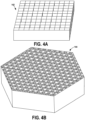
- Figures 4A and 4B illustrate example substrates 142, 144 generated by the additive manufacturing apparatus 114 and in accordance with the generated computational model of a the three-dimensional structure, according to example embodiments.
- the example substrate 144 can be trimmed such that the substrate 144 forms a hexagonal prism.
- the generating the computational model of the three dimensional structure involves trimming the edges of the structure to form a hexagonal prism.
- the substrate may be manufactured by the additive manufacturing apparatus 114 and then trimmed to form the hexagonal prism.
- additive manufacturing apparatus 114 operates in a layer-wise construction of a plurality of layers of material.
- the computational model of the three-dimensional includes overlapping areas (i.e., areas where the slats intersect one another), the computing device 116 of the additive manufacturing apparatus 114 does not distinguish overlapping areas. Rather, the additive manufacturing apparatus 114 only determines whether there is material or empty space for each layer. Accordingly, example systems and methods described herein eliminate the need to model perforations of substrate which, as noted above, can be computationally expensive, time consuming, and can cause machinery to shut down frequently.
- varying the dimensions of the slats, the distances between the slats, and the angle 133 of intersection of the first axis 122 and the second axis 128 creates different sizes and shapes of the apertures 132. Different sizes and shapes of the apertures 132 can be useful for various utilizations of the substrate in practice.
- larger apertures 132 may be desirable to provide a specific level of resistance to airflow into acoustic cell that resists and/or dampens a selected frequency (or frequencies) of acoustic energy.
- the height of the slats may provide an inductive response that regulates mass flow of air into an acoustic cell.
- the aperture 132 within the acoustic cell may define capacitance (energy store) of the cell, and further may resist airflow.
- volumes of free space within the acoustic cell may considered and programmatically controlled to control the acoustic properties of the acoustic cell and control and/or dampen specific frequencies. This technique may be particularly helpful in scenarios where specific frequencies of noise, for example, from an aircraft engine, are perceptible to passengers of the aircraft and are known to cause discomfort of the passengers.
- the additive manufacturing material for manufacturing the substrate may include many types of materials, such as a polymer (e.g., polycarbonate, nylon, epoxy resin), a ceramic (silica or glass), and a metal (steel, titanium alloy, aluminum alloys, etc.), for example.
- a polymer e.g., polycarbonate, nylon, epoxy resin
- a ceramic silica or glass
- a metal steel, titanium alloy, aluminum alloys, etc.
- the additive manufacturing material can be in many forms as well, such as powder, liquid, or a combination.
- Figure 5 illustrates another example implementation of a substrate 146, according to an example embodiment.
- the substrate 146 includes a first planar sheet 148 coupled to the bottom portion of the slats and second planar sheet 150 coupled to the top portion of the slats.
- the first planar sheet 148 and/or second planar sheet 150 can include apertures 152.
- the sheets 148, 150 can be generated with the computational model of the three-dimensional structure in any manner described above.
- first planar sheet 148, second planar sheet 150, and apertures 152 can be desirable for different utilizations of the substrate. For instance, in examples where the substrate is utilized as an acoustic panel, larger apertures 152 may be desirable to provide a specific level of resistance to airflow into acoustic cell that resists and/or dampens a selected frequency (or frequencies) of acoustic energy. Meanwhile, the height of the first planar sheet 148 and second planar sheet 150 may provide an inductive response that regulates mass flow of air into an acoustic cell.
- the aperture 152 within the first planar sheet 148 and second planar sheet 150 may define capacitance (energy store) of the cell, and further may resist airflow.
- volumes of free space within the planar sheets 148, 150 may be considered and programmatically controlled to control the acoustic properties of the acoustic cell and control and/or dampen specific frequencies. This technique may be particularly helpful in scenarios where specific frequencies of noise, for example, from an aircraft engine, are perceptible to passengers of the aircraft and are known to cause discomfort of the passengers.
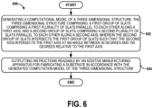
- Figure 6 shows a flowchart of an example of a method 600 that could be used with the systems for modeling apertures for additive manufacturing shown in Figures 1-5 .
- Method 600 may include one or more operations, functions, or actions as illustrated by one or more of blocks 602-604.
- the method 600 includes generating a computational model of a three-dimensional structure.
- the three-dimensional structure includes a first group of slats comprising a first plurality of slats parallel to each other along a first axis.
- the three-dimensional structure further includes a second group of slats comprising a second plurality of slats parallel to each other along a second axis, wherein the second group of slats intersects the first group of slats such that the second axis intersects the first axis at an angle between 30 degrees and 150 degrees relative to the first axis.
- generating the first group of slats comprises generating each of the first plurality of the first group of slats with a first height perpendicular to the first axis, wherein generating the second group of slats comprises generating each of the second plurality of slats with a second height perpendicular to the second axis, and wherein the first height and the second height are equal.
- the angle is a first angle
- generating the computational model of the three-dimensional structure further comprises generating a third group of slats comprising a third plurality of slats substantially parallel to each other along a third axis, and wherein the third group of slats intersects the first group of slats and the second group of slats such that the third axis intersects first axis at a second angle different than the first angle.
- generating a computational model of a three-dimensional structure further includes generating a first gap between each slat of the first plurality of slats, and generating the second group of slats includes generating a second gap between each of slat of the second plurality of slats.
- the first gap and the second gap are equal and the intersections of each first gap between each of the first plurality of slats with each second gap between each of the second plurality of slats define a plurality of apertures in the three-dimensional structure.
- the first group of slats aligned with a first axis and second group of slats aligned with a second axis define prism-shaped apertures, where the second group of slats intersects the first group of slats with the second axis intersecting the first axis at an angle between 30 degrees and 150 degrees relative to the first axis, such that the intersection of each first gap with each second gap may create rhombus-shaped or diamond-shaped apertures.
- the three-dimensional structure further comprises a third plurality of slats substantially parallel to each other along a third axis with a third gap between each of slat of the third plurality of slats, and the first axis, second axis and third axis each intersect each other at an angle
- the intersections of each first gap, each second gap and each third gap may define hexagon-shaped apertures as shown in FIG. 3B .
- generating a computational model of a three-dimensional structure includes generating a first planar sheet coupled to a bottom portion of the first group of slats and a bottom portion of the second group of slats, the first planar sheet comprising a first plurality of apertures.
- generating a computational model of a three-dimensional structure also includes generating a second planar sheet coupled to a top portion of the first group of slats and a top portion of the second group of slats, the second planar sheet comprising a second plurality of apertures.
- the method 600 includes outputting instructions readable by an additive manufacturing apparatus for fabricating a substrate in accordance with the generated computation model of the three-dimensional structure.
- the method 600 further includes manufacturing the substrate in accordance with the generated computation model of the three-dimensional structure. Further, in example implementations, the manufacturing the substrate in accordance with the generated computation model of the three-dimensional structure includes fabricating a septum of a cell of an acoustic panel.
- Devices or systems may be used or configured to perform logical functions presented in Figures 1-6 .
- components of the devices and/or systems may be configured to perform the functions such that the components are actually configured and structured (with hardware and/or software) to enable such performance.
- components of the devices and/or systems may be arranged to be adapted to, capable of, or suited for performing the functions, such as when operated in a specific manner.
- blocks in Figure 6 are illustrated in a sequential order, these blocks may also be performed in parallel, and/or in a different order than those described herein. Also, the various blocks may be combined into fewer blocks, divided into additional blocks, and/or removed based upon the desired implementation.
- each block or portions of each block may represent a module, a segment, or a portion of program code, which includes one or more instructions executable by a processor for implementing specific logical functions or steps in the process.
- the program code may be stored on any type of computer readable medium or data storage, for example, such as a storage device including a disk or hard drive. Further, the program code can be encoded on a computer-readable storage media in a machine-readable format, or on other non-transitory media or articles of manufacture.
- the computer readable medium may include non-transitory computer readable medium or memory, for example, such as computer-readable media that stores data for short periods of time like register memory, processor cache and Random Access Memory (RAM).
- the computer readable medium may also include non-transitory media, such as secondary or persistent long term storage, like read only memory (ROM), optical or magnetic disks, compact-disc read only memory (CD-ROM), for example.
- the computer readable media may also be any other volatile or non-volatile storage systems.
- the computer readable medium may be considered a tangible computer readable storage medium, for example.
- each block or portions of each block in Figure 6 may represent circuitry that is wired to perform the specific logical functions in the process.
- Alternative implementations are included within the scope of the examples of the present disclosure in which functions may be executed out of order from that shown or discussed, including substantially concurrent or in reverse order, depending on the functionality involved, as would be understood by those reasonably skilled in the art.
- system(s), device(s), and method(s) disclosed herein include a variety of components, features, and functionalities. It should be understood that the various examples of the system(s), device(s), and method(s) disclosed herein may include any of the components, features, and functionalities of any of the other examples of the system(s), device(s), and method(s) disclosed herein in any combination or any sub-combination, and all of such possibilities are intended to be within the scope of the disclosure.
Landscapes
- Engineering & Computer Science (AREA)
- Physics & Mathematics (AREA)
- Geometry (AREA)
- Materials Engineering (AREA)
- Chemical & Material Sciences (AREA)
- Manufacturing & Machinery (AREA)
- Theoretical Computer Science (AREA)
- General Physics & Mathematics (AREA)
- Computer Hardware Design (AREA)
- Evolutionary Computation (AREA)
- General Engineering & Computer Science (AREA)
- Mechanical Engineering (AREA)
- Pure & Applied Mathematics (AREA)
- Mathematical Optimization (AREA)
- Mathematical Analysis (AREA)
- Computational Mathematics (AREA)
- Acoustics & Sound (AREA)
- Multimedia (AREA)
- Optics & Photonics (AREA)
- Automation & Control Theory (AREA)
- Aviation & Aerospace Engineering (AREA)
- Soundproofing, Sound Blocking, And Sound Damping (AREA)
Abstract
Description
- The present disclosure relates generally to modeling apertures for additive manufacturing, and more particularly, to generating computational models for substrates including large scale patterned apertures for additive manufacturing. In examples, such substrates can be used for acoustic panels, among other implementations.
- Acoustic panels include structures that specifically designed to absorb, control and/or reflect sound. For example, acoustic panels may be utilized to reduce the noise impact of aircraft engines during takeoff, flight, and landing. Acoustic panels within an aircraft may further be utilized to reduce and/or redirect aircraft noise away from bystanders that may be proximate to an aircraft during takeoff and landing.
- Presently, acoustic panels are painstakingly assembled cell by cell in order to conform each panel to the complex geometries of an aircraft. A septum is inserted into each of these cells to facilitate control, and there may be tens of thousands of septa within the acoustic panels for an aircraft. Such intensive processes for inserting septa into acoustic panels increase the expense of manufacturing an aircraft, and are therefore undesirable. Hence, designers of aircraft carefully balance concerns of comfort and cost when adding acoustic panels to an aircraft.
- Therefore, it would be desirable to have a method and system that take into account at least some of the issues discussed above, as well as other possible issues.
- In an example, a system is described. The system comprises a computing device comprising a processor, the processor configured to carry out operations. The operations comprise generating a computational model of a three-dimensional structure. The three-dimensional structure comprises a first group of slats comprising a first plurality of slats substantially parallel to each other along a first axis and a second group of slats comprising a second plurality of slats substantially parallel to each other along a second axis. The second group of slats intersects the first group of slats such that the second axis intersects the first axis at an angle between 30 degrees and 150 degrees relative to the first axis. The operations further comprise outputting instructions for manufacturing a substrate in accordance with the generated computation model of the three-dimensional structure. The three-dimensional structure further comprises an additive manufacturing apparatus communicatively coupled to the computing device and configured to receive the instructions and manufacture the substrate in accordance with the generated computation model of the three-dimensional structure.
- In another example, a method is described. The method comprises generating a computational model of a three-dimensional structure. The three-dimensional structure comprises a first group of slats comprising a first plurality of slats parallel to each other along a first axis and a second group of slats comprising a second plurality of slats parallel to each other along a second axis. The second group of slats intersects the first group of slats such that the second axis intersects the first axis at an angle between 30 degrees and 150 degrees relative to the first axis. The method also includes outputting instructions readable by an additive manufacturing apparatus for fabricating a substrate in accordance with the generated computation model of the three-dimensional structure.
- In another example, a non-transitory computer-readable media is described. The non-transitory computer-readable media stores instructions executable by one or more signal processors. The instructions, when executed, cause the one or more signal processors to perform functions comprising generating a computational model of a three-dimensional structure. The three-dimensional structure comprises a first group of slats comprising a first plurality of slats parallel to each other along a first axis and a second group of slats comprising a second plurality of slats parallel to each other along a second axis. The second group of slats intersects the first group of slats such that the second axis intersects the first axis at an angle between 30 degrees and 150 degrees relative to the first axis. The instructions further comprise outputting instructions readable by an additive manufacturing apparatus for fabricating a substrate in accordance with the generated computation model of the three-dimensional structure.
- The features, functions, and advantages that have been discussed can be achieved independently in various examples or may be combined in yet other examples. Further details of the examples can be seen with reference to the following description and drawings.
- The novel features believed characteristic of the illustrative examples are set forth in the appended claims. The illustrative examples, however, as well as a preferred mode of use, further objectives and descriptions thereof, will best be understood by reference to the following detailed description of an illustrative example of the present disclosure when read in conjunction with the accompanying drawings, wherein:
-
Figure 1 depicts a computing system and additive manufacturing apparatus according to an example implementation. -
Figure 2A depicts a perspective view of a portion of a computation model of a three-dimensional structure according to an example implementation. -
Figure 2B depicts a perspective view of a portion a computation model of a three-dimensional structure according to an example implementation. -
Figure 3A depicts a top view of a three dimensional structure according to an example embodiment. -
Figure 3B depicts a top view of a computational model of a three dimensional structure according to an example embodiment. -
Figure 4A depicts a perspective view of a substrate manufactured in accordance with the computational model of the three-dimensional structure according to an example embodiment. -
Figure 4B depicts a perspective view of a substrate manufactured in accordance with the computational model of the three-dimensional structure according to an example embodiment. -
Figure 5 depicts a substrate manufactured in accordance with the computational model of the three-dimensional structure according to an example embodiment. -
Figure 6 shows a flowchart of an example method for generating computational model of a three-dimensional structure, according to an example implementation. - Disclosed examples will now be described more fully hereinafter with reference to the accompanying drawings, in which some, but not all of the disclosed examples are shown. Indeed, several different examples may be described and should not be construed as limited to the examples set forth herein. Rather, these examples are described so that this disclosure will be thorough and complete and will fully convey the scope of the disclosure to those skilled in the art.
- By the terms "substantially," "about," "approximately," and "proximate" used herein, it is meant that the recited characteristic, parameter, or value need not be achieved exactly, but that deviations or variations, including for example, tolerances, measurement error, measurement accuracy limitations and other factors known to skill in the art, may occur in amounts that do not preclude the effect the characteristic was intended to provide.
- Unless otherwise specifically noted, elements depicted in the drawings are not necessarily drawn to scale.
- Within examples, described herein are methods and systems for modeling apertures for additive manufacturing, particularly where a computational model of a three dimensional structure is developed. The computational model is readable by an additive manufacturing apparatus, such that a substrate is formed with apertures. Namely, methods and systems of the present disclosure provide the ability to manufacture materials with small, but large-scale apertures, such as acoustic cells, without the need for perforating material and/or inserting septa.
- These and other improvements are described in more detail below. Implementations described below are for purposes of example. The implementations described below, as well as other implementations, may provide other improvements as well.
- The disclosed methods and systems for modeling small perforations for additive manufacturing can be used in various contexts, such as in aircrafts or other vehicles, or in environments other than vehicles.
- Referring now to the figures,
Figure 1 depicts an example of asystem 100 for modeling apertures in additive manufacturing. The system includes acomputing device 102 configured to generate a model of three-dimensional structure and transmit anoutput file 110 to an additive manufacturing apparatus. - The
computing device 102 can take the form of a client device (e.g., a computing device that is actively operated by a user), a server, cloud computing device, or some other type of computational platform. In some examples, thecomputing device 102 can take the form of a desktop computer, laptop computer, tablet computer, smartphone, wearable computing device, or other type of device. Thecomputing device 102 can be in communication with an additive manufacturing apparatus 114. As such, thecomputing device 102 can receive information from additive manufacturing apparatus 114 and/or transmit information to additive manufacturing apparatus 114. For example, thecomputing device 102 can transmit an instruction to additive manufacturing apparatus 114 to cause the additive manufacturing apparatus 114 to manufacture a substrate in accordance with a generated computational model of a three-dimensional structure, the generated computational model of the three-dimensional shown inFigures 3A-5 and described in further detail below. - The
processor 104 can be a general-purpose processor or special purpose processor (e.g., a digital signal processor, application specific integrated circuit, etc.). Theprocessor 104 is configured to execute the instructions 108 (e.g., computer-readable program instructions including computer executable code) that are stored in thememory 106 and are executable to provide various operations described herein. In alternative examples, thecomputing device 102 can include additional processors that are configured in the same manner. At least some of the operations described herein as being performed by thecomputing device 102 can be performed by theprocessor 104. - The
memory 106 can take the form of one or more computer-readable storage media that can be read or accessed by theprocessor 104. The computer-readable storage media can include volatile and/or non-volatile storage components, such as optical, magnetic, organic or other memory or disc storage, which can be integrated in whole or in part with theprocessor 104. Thememory 106 is considered non-transitory computer readable media. In some examples, thememory 106 can be implemented using a single physical device (e.g., one optical, magnetic, organic or other memory or disc storage unit), while in other examples, thememory 106 can be implemented using two or more physical devices. - The communication link can take the form of any wired connection (e.g., Ethernet) or wireless connection (e.g., Bluetooth®) over which
computing device 102 and additive manufacturing apparatus 114 can engage in communication. For example, thecomputing device 102 can transmit anoutput file 110 to additive manufacturing apparatus 114. - In examples, the
output file 110 can includeinstructions 112 for manufacturing a substrate in accordance with a computational model of a three-dimensional structure, as shown inFigures 3A-5 . For instance, the additive manufacturing apparatus 114 can include acomputing device 116 configured to read theoutput file 110 and instructions. - Generally, the additive manufacturing apparatus operates by manufacturing parts in a layer-wise construction of a plurality of layers of material. Additive manufacturing may involve applying liquid or powder material to a work area, and then performing a combination of sintering, curing, melting, and/or cutting to create a layer. The process is repeated up to several thousand times to construct a desired finished part or apparatus. The additive manufacturing apparatus may include components, such as a printing head or printer nozzle, control mechanisms (e.g., computing device), molds, etc., depending on a type of manufacturing being used. A range of processes finding industrial applications for additive manufacturing includes direct metal deposition, electron beam melting, polymer processes such as fused filament fabrication (FFF), fused deposition (FDM), Solid Ground Curing (SGC), Laminated Object Manufacturing (LOM), and select laser sintering (SLS) or selective laser melting (SLM), among others. The additive manufacturing apparatus may include components specific to any of these processes, or in some examples, the additive manufacturing apparatus may include hybrid machine tools to combine additive manufacturing with subtractive machining. The additive manufacturing machine may additionally include a laser metal powder bed where a laser melts down the metal powder in material layers (e.g., direct metal laser sintering, selective laser melting).
- The substrate produced using the additive manufacturing apparatus is built up by laying down a layer of material on a build platform layer-by-layer. This process provides properties comparable to that of a casting.
- The additive manufacturing material for manufacturing a substrate may include many types of materials, such as a polymer (e.g., polycarbonate, nylon, epoxy resin), a ceramic (silica or glass), and a metal (steel, titanium alloy, aluminum alloys, etc.), for example. The additive manufacturing material can be in many forms as well, such as powder, liquid, or a combination.
- In some example embodiments, the
computing device 116 of the additive manufacturing apparatus 114 is configured to receive theoutput file 110 andinstructions 112 directly from thecomputing device 102 by way of a communication link, for example, as described above. Additionally, or alternatively, theoutput file 110 and instructions can be transmitted to the additive manufacturing apparatus 114 by way of a non-transitory computer readable medium. - Now referring to
Figures 2A-2B which illustrate initial steps of generating a computational model of a three-dimensional structure 120, according to an example embodiment. Developing a computational model involves generating a three-dimensional structure 120 of a first group ofslats 118. Each slat (e.g., 118a) in the group ofslats 118 can be generally rectangular prism shaped with sides extending along with a length, width, and a height. In example embodiments, theslat 118a is elongated in the length-wise direction such that the length of theslat 118a is substantially greater than the height and width of theslat 118a. Further, in examples, the height of theslat 118a may be greater than the width of theslat 118a. - An example three-
dimensional structure 120 includes a first group ofslats 118. Each of the slats in the first group ofslats 118 is identical or substantially identical. Namely, each slat in the first group ofslats 118 is an elongated rectangular prism, having the same length, height, and width as each other, with the length being substantially longer than the height or width of the rectangular prism. - Additionally, the slats are parallel, or substantially parallel to each other along a first axis 122 (i.e., the length-wise axis). Further, each slat in the first group of
slats 118 has a gap with adistance 124 between the nearest neighboring slat. In some examples, thisdistance 124 is the same between each of the slats, although other examples are possible. - Now referring
Figure 2B , generating the computational model of the three-dimensional structure 120 involves generating a second group ofslats 126. Each group of slats includes a plurality of slats which are parallel, or substantially parallel, along asecond axis 128 in a length-wise direction. Additionally, in examples, each group (i.e., the first group ofslats 118 and the second group of slats 126) has the same number of slats. - In some examples, the dimensions of each slat in the second group of
slats 126 are the same as each slat in the first group ofslats 118. Namely, the length, height, and width of each slat are the same in both groups of slats. In other examples, these dimensions of the slats may vary between the first group ofslats 118 and the second group ofslats 126. For example, the width of the slats in the second group ofslats 126 may be greater than the width of the slats in the first group ofslats 118. - Further, similar to the first group of
slats 118, each slat in the second group ofslats 126 has a gap having adistance 130 between the nearest neighboring slat. In some examples, thisdistance 124 is the same between each of the slats, although other examples are possible. - Further, in some examples,
distance 124 anddistance 130 are the same. Alternatively, in examples,distance 124 may be greater than or less thandistance 130. - As shown in
Figure 2B , the second group ofslats 126 intersects the first group of slats such that thesecond axis 128 intersects thefirst axis 122 at an angle. In some examples, the angle is between 30 degrees and 150 degrees. In other examples, the angle can be between 10 degrees and 170 degrees. Many examples are possible. - Further, while
Figure 2B illustrates a first group ofslats 118 and a second group ofslats 126, example three-dimensional structures can include any number of groups of slats. For example, a three-dimensional structure can include three groups of slats (as shown inFigures 3B and4B ) or more. - Now referring to
Figures 3A and 3B , a top view of a three dimensional structures according to an example embodiments. -
Figure 3A illustrates the first group ofslats 118 intersecting the second group ofslats 126 atangle 133. The example implementation shown inFigure 3A shows theangle 133 being about 90 degrees, however many examples, are possible. As noted above, in some examples, theangle 133 between thefirst axis 122 and thesecond axis 128 is between 30 degrees and 150 degrees. In other examples, theangle 133 can be between 10 degrees and 170 degrees. Many examples are possible. -
Figure 3B illustrates a top view of an example three-dimensional structure 120 with a first group ofslats 118, a second group ofslats 126, and a third group ofslats 134. The second group ofslats 126 intersects the first group of slats at afirst angle 133 with respect to thefirst axis 122 and thesecond axis 128. And the third group ofslats 134 intersects the first group ofslats 118 at asecond angle 136, different than thefirst angle 133, with respect to thefirst axis 122 and athird axis 138, where thethird axis 138 represents the length-wise axis of the third group ofslats 134. -
Figure 3B illustrates thefirst angle 133 and thesecond angle 136 being approximately 60 degrees and 120 degrees, respectively, however many examples, are possible. As noted above, in some examples, thefirst angle 133 andsecond angle 136 can be between 30 degrees and 150 degrees. In other examples, thefirst angle 133 andsecond angle 136 can be between 10 degrees and 170 degrees. - As shown in
Figures 3A and 3B , the gaps between slats createapertures 132 between the slats. Varying the dimensions of the slats (e.g., the width and length), thedistances angle 133 of intersection of thefirst axis 122 and thesecond axis 128 creates different sizes and shapes of theapertures 132. Different sizes and shapes of theapertures 132 can be useful for various utilizations of the substrate generated in accordance with the computational model of the three-dimensional structure in practice, as discussed in more detail below. - As noted above, although the example embodiments shown in
Figures 3A and 3B include two groups of slats and three groups of slats, respectively, example three-dimensional structures can include any number of groups of slats. For example, a three-dimensional structure can include four or more groups of slats. - Referring back to
Figure 1 , once the model of the three-dimensional structure 120 is generated, thecomputing device 102 can then transmit theoutput file 110 to an additive manufacturing apparatus 114. Theoutput file 110 includes instructions readable by the additive manufacturing apparatus 114 for manufacturing a substrate in accordance with the generated computation model of the three-dimensional structure. -
Figures 4A and 4B illustrateexample substrates - As shown in
Figure 4B , theexample substrate 144 can be trimmed such that thesubstrate 144 forms a hexagonal prism. In some examples, the generating the computational model of the three dimensional structure involves trimming the edges of the structure to form a hexagonal prism. In other examples, the substrate may be manufactured by the additive manufacturing apparatus 114 and then trimmed to form the hexagonal prism. - As noted above, additive manufacturing apparatus 114 operates in a layer-wise construction of a plurality of layers of material. Although, the computational model of the three-dimensional includes overlapping areas (i.e., areas where the slats intersect one another), the
computing device 116 of the additive manufacturing apparatus 114 does not distinguish overlapping areas. Rather, the additive manufacturing apparatus 114 only determines whether there is material or empty space for each layer. Accordingly, example systems and methods described herein eliminate the need to model perforations of substrate which, as noted above, can be computationally expensive, time consuming, and can cause machinery to shut down frequently. - Further, varying the dimensions of the slats, the distances between the slats, and the
angle 133 of intersection of thefirst axis 122 and thesecond axis 128 creates different sizes and shapes of theapertures 132. Different sizes and shapes of theapertures 132 can be useful for various utilizations of the substrate in practice. - For instance, in examples where the substrate is utilized as an acoustic panel,
larger apertures 132 may be desirable to provide a specific level of resistance to airflow into acoustic cell that resists and/or dampens a selected frequency (or frequencies) of acoustic energy. Meanwhile, the height of the slats may provide an inductive response that regulates mass flow of air into an acoustic cell. Theaperture 132 within the acoustic cell may define capacitance (energy store) of the cell, and further may resist airflow. Thus, volumes of free space within the acoustic cell may considered and programmatically controlled to control the acoustic properties of the acoustic cell and control and/or dampen specific frequencies. This technique may be particularly helpful in scenarios where specific frequencies of noise, for example, from an aircraft engine, are perceptible to passengers of the aircraft and are known to cause discomfort of the passengers. - As noted above, the additive manufacturing material for manufacturing the substrate (e.g., 142, 144) may include many types of materials, such as a polymer (e.g., polycarbonate, nylon, epoxy resin), a ceramic (silica or glass), and a metal (steel, titanium alloy, aluminum alloys, etc.), for example. The additive manufacturing material can be in many forms as well, such as powder, liquid, or a combination.
-
Figure 5 illustrates another example implementation of asubstrate 146, according to an example embodiment. As shown inFigure 5 , in some examples, thesubstrate 146 includes a firstplanar sheet 148 coupled to the bottom portion of the slats and secondplanar sheet 150 coupled to the top portion of the slats. Within examples, the firstplanar sheet 148 and/or secondplanar sheet 150 can includeapertures 152. - In examples where the
substrate 146 includes the firstplanar sheet 148 and/or second planar sheet, thesheets - Various dimensions of the first
planar sheet 148, secondplanar sheet 150, andapertures 152 can be desirable for different utilizations of the substrate. For instance, in examples where the substrate is utilized as an acoustic panel,larger apertures 152 may be desirable to provide a specific level of resistance to airflow into acoustic cell that resists and/or dampens a selected frequency (or frequencies) of acoustic energy. Meanwhile, the height of the firstplanar sheet 148 and secondplanar sheet 150 may provide an inductive response that regulates mass flow of air into an acoustic cell. Theaperture 152 within the firstplanar sheet 148 and secondplanar sheet 150 may define capacitance (energy store) of the cell, and further may resist airflow. Thus, volumes of free space within theplanar sheets -
Figure 6 shows a flowchart of an example of amethod 600 that could be used with the systems for modeling apertures for additive manufacturing shown inFigures 1-5 .Method 600 may include one or more operations, functions, or actions as illustrated by one or more of blocks 602-604. - At
block 602, themethod 600 includes generating a computational model of a three-dimensional structure. In examples, the three-dimensional structure includes a first group of slats comprising a first plurality of slats parallel to each other along a first axis. The three-dimensional structure further includes a second group of slats comprising a second plurality of slats parallel to each other along a second axis, wherein the second group of slats intersects the first group of slats such that the second axis intersects the first axis at an angle between 30 degrees and 150 degrees relative to the first axis. - In some example implementations, generating the first group of slats comprises generating each of the first plurality of the first group of slats with a first height perpendicular to the first axis, wherein generating the second group of slats comprises generating each of the second plurality of slats with a second height perpendicular to the second axis, and wherein the first height and the second height are equal.
- Further, in some example implementations, the angle is a first angle, and generating the computational model of the three-dimensional structure further comprises generating a third group of slats comprising a third plurality of slats substantially parallel to each other along a third axis, and wherein the third group of slats intersects the first group of slats and the second group of slats such that the third axis intersects first axis at a second angle different than the first angle.
- Additionally, in some example implementations, generating a computational model of a three-dimensional structure further includes generating a first gap between each slat of the first plurality of slats, and generating the second group of slats includes generating a second gap between each of slat of the second plurality of slats. In these examples, the first gap and the second gap are equal and the intersections of each first gap between each of the first plurality of slats with each second gap between each of the second plurality of slats define a plurality of apertures in the three-dimensional structure. The first group of slats aligned with a first axis and second group of slats aligned with a second axis define prism-shaped apertures, where the second group of slats intersects the first group of slats with the second axis intersecting the first axis at an angle between 30 degrees and 150 degrees relative to the first axis, such that the intersection of each first gap with each second gap may create rhombus-shaped or diamond-shaped apertures. Where the three-dimensional structure further comprises a third plurality of slats substantially parallel to each other along a third axis with a third gap between each of slat of the third plurality of slats, and the first axis, second axis and third axis each intersect each other at an angle, the intersections of each first gap, each second gap and each third gap may define hexagon-shaped apertures as shown in
FIG. 3B . - In example embodiments, generating a computational model of a three-dimensional structure includes generating a first planar sheet coupled to a bottom portion of the first group of slats and a bottom portion of the second group of slats, the first planar sheet comprising a first plurality of apertures. In examples, generating a computational model of a three-dimensional structure also includes generating a second planar sheet coupled to a top portion of the first group of slats and a top portion of the second group of slats, the second planar sheet comprising a second plurality of apertures.
- At
block 604, themethod 600 includes outputting instructions readable by an additive manufacturing apparatus for fabricating a substrate in accordance with the generated computation model of the three-dimensional structure. - In example implementations, the
method 600 further includes manufacturing the substrate in accordance with the generated computation model of the three-dimensional structure. Further, in example implementations, the manufacturing the substrate in accordance with the generated computation model of the three-dimensional structure includes fabricating a septum of a cell of an acoustic panel. - Devices or systems may be used or configured to perform logical functions presented in
Figures 1-6 . In some instances, components of the devices and/or systems may be configured to perform the functions such that the components are actually configured and structured (with hardware and/or software) to enable such performance. In other examples, components of the devices and/or systems may be arranged to be adapted to, capable of, or suited for performing the functions, such as when operated in a specific manner. Although blocks inFigure 6 , are illustrated in a sequential order, these blocks may also be performed in parallel, and/or in a different order than those described herein. Also, the various blocks may be combined into fewer blocks, divided into additional blocks, and/or removed based upon the desired implementation. - It should be understood that for these and other processes and methods disclosed herein, flowcharts show functionality and operation of one possible implementation of present examples. In this regard, each block or portions of each block may represent a module, a segment, or a portion of program code, which includes one or more instructions executable by a processor for implementing specific logical functions or steps in the process. The program code may be stored on any type of computer readable medium or data storage, for example, such as a storage device including a disk or hard drive. Further, the program code can be encoded on a computer-readable storage media in a machine-readable format, or on other non-transitory media or articles of manufacture. The computer readable medium may include non-transitory computer readable medium or memory, for example, such as computer-readable media that stores data for short periods of time like register memory, processor cache and Random Access Memory (RAM). The computer readable medium may also include non-transitory media, such as secondary or persistent long term storage, like read only memory (ROM), optical or magnetic disks, compact-disc read only memory (CD-ROM), for example. The computer readable media may also be any other volatile or non-volatile storage systems. The computer readable medium may be considered a tangible computer readable storage medium, for example.
- In addition, each block or portions of each block in
Figure 6 may represent circuitry that is wired to perform the specific logical functions in the process. Alternative implementations are included within the scope of the examples of the present disclosure in which functions may be executed out of order from that shown or discussed, including substantially concurrent or in reverse order, depending on the functionality involved, as would be understood by those reasonably skilled in the art. - Further, the disclosure comprises embodiments according to the following clauses:
- Clause 1. A system (100) comprising:
a computing device (102) comprising a processor (104), the processor (104) configured to carry out operations, the operations comprising: - generating a computational model of a three-dimensional structure (120), the three-dimensional structure (120) comprising:
- a first group of slats (118) comprising a first plurality of slats substantially parallel to each other along a first axis (122); and
- a second group of slats (126) comprising a second plurality of slats substantially parallel to each other along a second axis (128), wherein the second group of slats (126) intersects the first group of slats (118) such that the second axis (128) intersects the first axis (122) at an angle (133) between 30 degrees and 150 degrees relative to the first axis (122); and
- outputting instructions (108) for manufacturing a substrate (142) in accordance with the generated computation model of the three-dimensional structure (120); and
an additive manufacturing apparatus (114) communicatively coupled to the computing device (102) and configured to receive the instructions (108) and manufacture the substrate (142) in accordance with the generated computation model of the three-dimensional structure (120).
- Clause 2. The system (100) of clause 1, wherein generating the first group of slats (118) comprises generating each of the first plurality of the first group of slats with a first height perpendicular to the first axis (122), wherein generating the second group of slats (126) comprises generating each of the second plurality of slats with a second height perpendicular to the second axis (128), and wherein the first height and the second height are equal.
- Clause 3. The system (100) of any preceding clause, wherein generating the three-dimensional structure (120) further comprises generating a third group of slats (134) comprising a third plurality of slats substantially parallel to each other along a third axis (138), and wherein the third group of slats (134) intersects the first group of slats (118) and the second group of slats (126) such that the third axis (138) intersects the first axis at a second angle(136), different than the first angle (133).
- Clause 4. The system (100) of clause 3, wherein the first group of slats (118) has a first height perpendicular to the first axis (122), the second group of slats (126) has a second height perpendicular to the second axis (128), and the third group of slats (134) has a third height perpendicular to the third axis (138), and wherein the first height, the second height, and the third height are equal.
- Clause 5. The system (100) of any preceding clause, wherein the substrate comprises a septum (132) of a cell of an acoustic panel.
- Clause 6. The system (100) of any preceding clause, wherein generating the first group of slats (118) comprises generating a first gap (124) between each slat of the first plurality of slats, and generating the second group of slats comprises generating a second gap (130) between each of slat of the second plurality of slats.
- Clause 7. The system (100) of clause 6, wherein the first gap (124) and the second gap (130) are equal and the intersections of each first gap between each of the first plurality of slats with each second gap between each of the second plurality of slats define a plurality of apertures (132) in the three-dimensional structure.
- Clause 8. The system (100) of clause 7, wherein the three-dimensional structure (120) comprises a plurality of apertures (132) that are generally prism-shaped, the apertures (132) being identical to each other.
- Clause 9. The system (100) of any preceding clause, wherein generating the three-dimensional structure (120) further comprises generating:
- a first planar sheet (148) coupled to a bottom portion of the first group of slats (118) and a bottom portion of the second group of slats (126), the first planar sheet (148) comprising a first plurality of apertures; and
- a second planar sheet (150) coupled to a top portion of the first group of slats (118) and a top portion of the second group of slats (126), the second planar sheet (150) comprising a second plurality of apertures (152).
- Clause 10. A method (600) comprising:
generating a computational model of a three-dimensional structure (120), the three-dimensional structure (120) comprising:- a first group of slats (118) comprising a first plurality of slats parallel to each other along a first axis (122); and
- a second group of slats (126) comprising a second plurality of slats parallel to each other along a second axis (128), wherein the second group of slats intersects the first group of slats (118) such that the second axis (128) intersects the first axis (122) at an angle between 30 degrees and 150 degrees relative to the first axis (122); and
- outputting instructions (112) readable by an additive manufacturing apparatus (114) for fabricating a substrate (142) in accordance with the generated computation model of the three-dimensional structure (120).
- Clause 11. The method (600) of clause 10, further comprising:
manufacturing the substrate (142) in accordance with the generated computation model of the three-dimensional structure (120). - Clause 12. The method (600) of clause 11, wherein manufacturing the substrate (142) in accordance with the generated computation model of the three-dimensional structure (120) comprises fabricating a septum (132) of a cell of an acoustic panel.
-
Clause 13. The method (600) of any of clauses 10 to 12, wherein generating the first group of slats (118) comprises generating each of the first plurality of the first group of slats (118) with a first height perpendicular to the first axis (122), wherein generating the second group of slats (126) comprises generating each of the second plurality of slats with a second height perpendicular to the second axis (128), and wherein the first height and the second height are equal. - Clause 14. The method (600) of any of clauses 10 to 13, wherein the angle is a first angle (133), wherein generating the computational model of the three-dimensional structure (120) further comprises generating a third group of slats (134) comprising a third plurality of slats substantially parallel to each other along a third axis (138), and wherein the third group of slats (134) intersects the first group of slats (118) and the second group of slats (126) such that the third axis (138) intersects first axis (122) at a second angle (136) different than the first angle (133).
- Clause 15. The method (600) of any of clauses 10 to 14, wherein generating a computational model of a three-dimensional structure (120) further comprises generating a first gap (124) between each slat of the first plurality of slats, and generating the second group of slats (126) comprises generating a second gap (130) between each of slat of the second plurality of slats, wherein the first gap (124) and the second gap (130) are equal and the intersections of each first gap between each of the first plurality of slats with each second gap between each of the second plurality of slats define a plurality of apertures (132) in the three-dimensional structure (120).
- Clause 16. The method (600) of any of clauses 10 to 15, wherein generating a computational model of a three-dimensional structure (120), further comprises generating:
- a first planar sheet (148) coupled to a bottom portion of the first group of slats (118) and a bottom portion of the second group of slats (126), the first planar sheet (148) comprising a first plurality of apertures; and
- a second planar sheet (150) coupled to a top portion of the first group of slats (118) and a top portion of the second group of slats (126), the second planar sheet comprising a second plurality of apertures (152).
- Clause 17. A non-transitory computer-readable media storing instructions executable by one or more signal processors (104), wherein the instructions, when executed, cause the one or more signal processors to perform functions comprising:
generating a computational model of a three-dimensional structure (120), the three-dimensional structure comprising:- a first group of slats (118) comprising a first plurality of slats parallel to each other along a first axis (122); and
- a second group of slats (126) comprising a second plurality of slats parallel to each other along a second axis (128), wherein the second group of slats (126) intersects the first group of slats (118) such that the second axis (128) intersects the first axis (122) at an angle (133) between 30 degrees and 150 degrees relative to the first axis (122); and
- outputting instructions (108) readable by an additive manufacturing apparatus (114) for fabricating a substrate (142) in accordance with the generated computation model of the three-dimensional structure (120).
- Clause 18. The non-transitory computer-readable media of clause 17, wherein the functions further comprise:
transmitting the instructions (108) to an additive manufacturing apparatus (114) communicatively coupled to the processor (104). - Clause 19. The non-transitory computer-readable media of clause 17 or 18, wherein the angle (133) is a first angle (133), wherein generating the computational model of the three-dimensional structure (120) further comprises generating:
a third group of slats (134) comprising a third plurality of slats substantially parallel to each other along a third axis (138), and wherein the third group of slats intersects the first group of slats (118) and the second group of slats (126) such that the third axis (138) intersects first axis (122) at a second angle (136) different than the first angle (133). - Clause 20. The non-transitory computer-readable media according to any of clauses 17 to 19, wherein generating a computational model of a three-dimensional structure (120), further comprises generating:
- a first planar sheet (148) coupled to a bottom portion of the first group of slats (118) and a bottom portion of the second group of slats (126), the first planar sheet (148) comprising a first plurality of apertures; and
- a second planar sheet (150) coupled to a top portion of the first group of slats (118) and a top portion of the second group of slats (126), the second planar sheet (150) comprising a second plurality of apertures (152).
- Different examples of the system(s), device(s), and method(s) disclosed herein include a variety of components, features, and functionalities. It should be understood that the various examples of the system(s), device(s), and method(s) disclosed herein may include any of the components, features, and functionalities of any of the other examples of the system(s), device(s), and method(s) disclosed herein in any combination or any sub-combination, and all of such possibilities are intended to be within the scope of the disclosure.
- The description of the different advantageous arrangements has been presented for purposes of illustration and description, and is not intended to be exhaustive or limited to the examples in the form disclosed. Many modifications and variations will be apparent to those of ordinary skill in the art. Further, different advantageous examples may describe different advantages as compared to other advantageous examples. The example or examples selected are chosen and described in order to best explain the principles of the examples, the practical application, and to enable others of ordinary skill in the art to understand the disclosure for various examples with various modifications as are suited to the particular use contemplated.
Claims (15)
- A system (100) comprising:a computing device (102) comprising a processor (104), the processor (104) configured to carry out operations, the operations comprising:generating a computational model of a three-dimensional structure (120), the three-dimensional structure (120) comprising:a first group of slats (118) comprising a first plurality of slats substantially parallel to each other along a first axis (122); anda second group of slats (126) comprising a second plurality of slats substantially parallel to each other along a second axis (128), wherein the second group of slats (126) intersects the first group of slats (118) such that the second axis (128) intersects the first axis (122) at an angle (133) between 30 degrees and 150 degrees relative to the first axis (122); andoutputting instructions (108) for manufacturing a substrate (142) in accordance with the generated computation model of the three-dimensional structure (120); andan additive manufacturing apparatus (114) communicatively coupled to the computing device (102) and configured to receive the instructions (108) and manufacture the substrate (142) in accordance with the generated computation model of the three-dimensional structure (120).
- The system (100) of claim 1, wherein generating the first group of slats (118) comprises generating each of the first plurality of the first group of slats with a first height perpendicular to the first axis (122), wherein generating the second group of slats (126) comprises generating each of the second plurality of slats with a second height perpendicular to the second axis (128), and wherein the first height and the second height are equal.
- The system (100) of claim 1, wherein generating the three-dimensional structure (120) further comprises generating a third group of slats (134) comprising a third plurality of slats substantially parallel to each other along a third axis (138), and wherein the third group of slats (134) intersects the first group of slats (118) and the second group of slats (126) such that the third axis (138) intersects the first axis at a second angle(136), different than the first angle (133).
- The system (100) of claim 3, wherein the first group of slats (118) has a first height perpendicular to the first axis (122), the second group of slats (126) has a second height perpendicular to the second axis (128), and the third group of slats (134) has a third height perpendicular to the third axis (138), and wherein the first height, the second height, and the third height are equal.
- The system (100) of any of claims 1 to 4, wherein the substrate comprises a septum (132) of a cell of an acoustic panel.
- The system (100) of any of claims 1 to 5, wherein generating the first group of slats (118) comprises generating a first gap (124) between each slat of the first plurality of slats, and generating the second group of slats comprises generating a second gap (130) between each of slat of the second plurality of slats.
- The system (100) of claim 6, wherein the first gap (124) and the second gap (130) are equal and the intersections of each first gap between each of the first plurality of slats with each second gap between each of the second plurality of slats define a plurality of apertures (132) in the three-dimensional structure.
- The system (100) of claim 7, wherein the three-dimensional structure (120) comprises a plurality of apertures (132) that are generally prism-shaped, the apertures (132) being identical to each other.
- The system (100) of any of claims 1 to 8, wherein generating the three-dimensional structure (120) further comprises generating:a first planar sheet (148) coupled to a bottom portion of the first group of slats (118) and a bottom portion of the second group of slats (126), the first planar sheet (148) comprising a first plurality of apertures; anda second planar sheet (150) coupled to a top portion of the first group of slats (118) and a top portion of the second group of slats (126), the second planar sheet (150) comprising a second plurality of apertures (152).
- A method (600) comprising:
generating a computational model of a three-dimensional structure (120), the three-dimensional structure (120) comprising:a first group of slats (118) comprising a first plurality of slats parallel to each other along a first axis (122); anda second group of slats (126) comprising a second plurality of slats parallel to each other along a second axis (128), wherein the second group of slats intersects the first group of slats (118) such that the second axis (128) intersects the first axis (122) at an angle between 30 degrees and 150 degrees relative to the first axis (122); andoutputting instructions (112) readable by an additive manufacturing apparatus (114) for fabricating a substrate (142) in accordance with the generated computation model of the three-dimensional structure (120). - The method (600) according to claim 10, further comprising:
manufacturing the substrate (142) in accordance with the generated computation model of the three-dimensional structure (120). - The method (600) according to claim 11, wherein manufacturing the substrate (142) in accordance with the generated computation model of the three-dimensional structure (120) comprises fabricating a septum (132) of a cell of an acoustic panel.
- The method (600) according to any of claims 10 to 12, wherein generating the first group of slats (118) comprises generating each of the first plurality of the first group of slats (118) with a first height perpendicular to the first axis (122), wherein generating the second group of slats (126) comprises generating each of the second plurality of slats with a second height perpendicular to the second axis (128), and wherein the first height and the second height are equal.
- The method (600) according to any of claims 10 to 13, wherein the angle is a first angle (133), wherein generating the computational model of the three-dimensional structure (120) further comprises generating a third group of slats (134) comprising a third plurality of slats substantially parallel to each other along a third axis (138), and wherein the third group of slats (134) intersects the first group of slats (118) and the second group of slats (126) such that the third axis (138) intersects first axis (122) at a second angle (136) different than the first angle (133).
- The method (600) of any of claims 10 to 14, wherein generating a computational model of a three-dimensional structure (120) further comprises generating a first gap (124) between each slat of the first plurality of slats, and generating the second group of slats (126) comprises generating a second gap (130) between each of slat of the second plurality of slats, wherein the first gap (124) and the second gap (130) are equal and the intersections of each first gap between each of the first plurality of slats with each second gap between each of the second plurality of slats define a plurality of apertures (132) in the three-dimensional structure (120).
Applications Claiming Priority (1)
| Application Number | Priority Date | Filing Date | Title |
|---|---|---|---|
| US17/845,659 US20230405937A1 (en) | 2022-06-21 | 2022-06-21 | Methods and systems for modeling apertures for additive manufacturing |
Publications (1)
| Publication Number | Publication Date |
|---|---|
| EP4296879A1 true EP4296879A1 (en) | 2023-12-27 |
Family
ID=85800743
Family Applications (1)
| Application Number | Title | Priority Date | Filing Date |
|---|---|---|---|
| EP23165986.3A Pending EP4296879A1 (en) | 2022-06-21 | 2023-03-31 | Methods and systems for modeling apertures for additive manufacturing |
Country Status (4)
| Country | Link |
|---|---|
| US (1) | US20230405937A1 (en) |
| EP (1) | EP4296879A1 (en) |
| JP (1) | JP2024000993A (en) |
| CN (1) | CN117272499A (en) |
Citations (3)
| Publication number | Priority date | Publication date | Assignee | Title |
|---|---|---|---|---|
| US20200049074A1 (en) * | 2018-08-09 | 2020-02-13 | General Electric Company | Acoustic panel and method for making the same |
| US20200193952A1 (en) * | 2018-12-12 | 2020-06-18 | Korea Institute Of Science And Technology | Sound absorption structure and method of manufacturing the same |
| US20210254522A1 (en) * | 2020-02-18 | 2021-08-19 | Divergent Technologies, Inc. | Impact energy absorber with integrated engine exhaust noise muffler |
Family Cites Families (3)
| Publication number | Priority date | Publication date | Assignee | Title |
|---|---|---|---|---|
| EP2393648B1 (en) * | 2009-02-03 | 2012-11-07 | Airbus Opérations SAS | Method for making a network of drainage pipes for an acoustic processing panel |
| DE102015110360A1 (en) * | 2015-06-26 | 2016-12-29 | Bundesrepublik Deutschland, Vertreten Durch Den Bundesminister Für Wirtschaft Und Energie, Dieser Vertreten Durch Den Präsidenten Der Bundesanstalt Für Materialforschung Und -Prüfung (Bam) | Method for laser-induced additive production of a green body by means of slip casting |
| JP7538828B2 (en) * | 2021-03-16 | 2024-08-22 | プーマ エス イー | Method for producing a part of a footwear article from a form - Patents.com |
-
2022
- 2022-06-21 US US17/845,659 patent/US20230405937A1/en active Pending
-
2023
- 2023-03-31 EP EP23165986.3A patent/EP4296879A1/en active Pending
- 2023-04-12 CN CN202310392713.6A patent/CN117272499A/en active Pending
- 2023-06-20 JP JP2023100618A patent/JP2024000993A/en active Pending
Patent Citations (3)
| Publication number | Priority date | Publication date | Assignee | Title |
|---|---|---|---|---|
| US20200049074A1 (en) * | 2018-08-09 | 2020-02-13 | General Electric Company | Acoustic panel and method for making the same |
| US20200193952A1 (en) * | 2018-12-12 | 2020-06-18 | Korea Institute Of Science And Technology | Sound absorption structure and method of manufacturing the same |
| US20210254522A1 (en) * | 2020-02-18 | 2021-08-19 | Divergent Technologies, Inc. | Impact energy absorber with integrated engine exhaust noise muffler |
Also Published As
| Publication number | Publication date |
|---|---|
| US20230405937A1 (en) | 2023-12-21 |
| JP2024000993A (en) | 2024-01-09 |
| CN117272499A (en) | 2023-12-22 |
Similar Documents
| Publication | Publication Date | Title |
|---|---|---|
| US11947334B2 (en) | Macrostructure topology generation with disparate physical simulation for Computer Aided Design and Manufacturing | |
| US7406361B2 (en) | Rapid prototyping method and apparatus using V-CAD data | |
| CN104050314B (en) | Additive topology optimized manufacturing for multi-functional components | |
| Hashimoto et al. | Drag prediction on NASA common research model using automatic hexahedra grid-generation method | |
| CN113836828B (en) | System and method for combined differentiable partial differential equation solver and graphical neural network for fluid flow prediction | |
| US10802467B2 (en) | Methods of defining internal structures for additive manufacturing | |
| JP6033668B2 (en) | CAM device and product shape processing method | |
| US12282310B2 (en) | Dual lattice representation for simulation and manufacturing | |
| CN104417745A (en) | Structural inserts for honeycomb structures | |
| JP2011501251A (en) | Method and apparatus for automatically generating a support for an object manufactured by a rapid prototype manufacturing method | |
| JP6861786B2 (en) | Local control of surface design patterns to enhance physical properties | |
| CN114474741B (en) | A multi-axis unsupported 3D printing surface slicing method, device and server | |
| CN103399996A (en) | Multi-target topological optimization design method for flexible mechanism for fast servo tool rest | |
| CN111386163A (en) | Apparatus and method for additively manufacturing grid structures | |
| CN106960088A (en) | The three-dimensional process model automatic update method changed towards process | |
| JP2017177462A (en) | Structure strength prediction method, structure modeling method, structure additive manufacturing method and program | |
| EP4022487B1 (en) | Object design processing using coarse geometric elements and high-resolution lattice elements | |
| EP4296879A1 (en) | Methods and systems for modeling apertures for additive manufacturing | |
| US20200387652A1 (en) | Computational Modeling of Procedural Language Descriptors Prior to Manufacture | |
| US20080100619A1 (en) | Mesh generation method and computer-readable article for executing the method | |
| Gibson et al. | Software for additive manufacturing | |
| CN117235924A (en) | Optimal design and manufacturing method of three-dimensional self-supporting truss based on multi-axis 3D printing | |
| CN114556437A (en) | Method of generating a grid of parts, method of using a grid of parts, computer program and computer readable medium | |
| CN113296536A (en) | Unmanned aerial vehicle three-dimensional obstacle avoidance algorithm based on A-star and convex optimization algorithm | |
| Chung | A level set approach for computing solutions to inviscid compressible flow with moving solid boundary using fixed Cartesian grids |
Legal Events
| Date | Code | Title | Description |
|---|---|---|---|
| PUAI | Public reference made under article 153(3) epc to a published international application that has entered the european phase |
Free format text: ORIGINAL CODE: 0009012 |
|
| STAA | Information on the status of an ep patent application or granted ep patent |
Free format text: STATUS: THE APPLICATION HAS BEEN PUBLISHED |
|
| AK | Designated contracting states |
Kind code of ref document: A1 Designated state(s): AL AT BE BG CH CY CZ DE DK EE ES FI FR GB GR HR HU IE IS IT LI LT LU LV MC ME MK MT NL NO PL PT RO RS SE SI SK SM TR |
|
| STAA | Information on the status of an ep patent application or granted ep patent |
Free format text: STATUS: REQUEST FOR EXAMINATION WAS MADE |
|
| 17P | Request for examination filed |
Effective date: 20240627 |
|
| RBV | Designated contracting states (corrected) |
Designated state(s): AL AT BE BG CH CY CZ DE DK EE ES FI FR GB GR HR HU IE IS IT LI LT LU LV MC ME MK MT NL NO PL PT RO RS SE SI SK SM TR |
|
| STAA | Information on the status of an ep patent application or granted ep patent |
Free format text: STATUS: EXAMINATION IS IN PROGRESS |
|
| 17Q | First examination report despatched |
Effective date: 20251208 |