EP4296803A1 - Vorrichtungskonfigurationsobjektvorlage mit benutzerinteraktion für vorrichtungseigenschaftsgenerator - Google Patents
Vorrichtungskonfigurationsobjektvorlage mit benutzerinteraktion für vorrichtungseigenschaftsgenerator Download PDFInfo
- Publication number
- EP4296803A1 EP4296803A1 EP23175064.7A EP23175064A EP4296803A1 EP 4296803 A1 EP4296803 A1 EP 4296803A1 EP 23175064 A EP23175064 A EP 23175064A EP 4296803 A1 EP4296803 A1 EP 4296803A1
- Authority
- EP
- European Patent Office
- Prior art keywords
- device configuration
- configuration interface
- industrial
- user
- project
- Prior art date
- Legal status (The legal status is an assumption and is not a legal conclusion. Google has not performed a legal analysis and makes no representation as to the accuracy of the status listed.)
- Pending
Links
- 230000003993 interaction Effects 0.000 title claims abstract description 142
- 230000033001 locomotion Effects 0.000 claims abstract description 15
- 238000000034 method Methods 0.000 claims description 55
- 230000009471 action Effects 0.000 claims description 19
- 230000004044 response Effects 0.000 claims description 17
- 238000009877 rendering Methods 0.000 claims description 4
- 238000011161 development Methods 0.000 abstract description 42
- 238000013461 design Methods 0.000 description 62
- 238000003860 storage Methods 0.000 description 52
- 230000018109 developmental process Effects 0.000 description 44
- 238000012800 visualization Methods 0.000 description 43
- 238000010586 diagram Methods 0.000 description 30
- 238000004891 communication Methods 0.000 description 23
- 230000000875 corresponding effect Effects 0.000 description 22
- 230000006870 function Effects 0.000 description 21
- 230000008569 process Effects 0.000 description 19
- 238000013459 approach Methods 0.000 description 14
- 238000012544 monitoring process Methods 0.000 description 11
- 238000012545 processing Methods 0.000 description 11
- 238000004519 manufacturing process Methods 0.000 description 10
- 238000004458 analytical method Methods 0.000 description 9
- 230000006855 networking Effects 0.000 description 8
- 230000001276 controlling effect Effects 0.000 description 7
- 238000005516 engineering process Methods 0.000 description 6
- 238000009434 installation Methods 0.000 description 6
- 230000003287 optical effect Effects 0.000 description 6
- 238000012360 testing method Methods 0.000 description 6
- 238000013499 data model Methods 0.000 description 5
- 239000000463 material Substances 0.000 description 5
- 239000002609 medium Substances 0.000 description 5
- 238000013473 artificial intelligence Methods 0.000 description 4
- 230000002452 interceptive effect Effects 0.000 description 4
- 238000012986 modification Methods 0.000 description 4
- 230000004048 modification Effects 0.000 description 4
- 238000010923 batch production Methods 0.000 description 3
- 230000008901 benefit Effects 0.000 description 3
- 238000013479 data entry Methods 0.000 description 3
- 239000003814 drug Substances 0.000 description 3
- 229940079593 drug Drugs 0.000 description 3
- 230000002093 peripheral effect Effects 0.000 description 3
- 230000001902 propagating effect Effects 0.000 description 3
- 238000013515 script Methods 0.000 description 3
- 239000007787 solid Substances 0.000 description 3
- 230000003190 augmentative effect Effects 0.000 description 2
- 238000003339 best practice Methods 0.000 description 2
- 238000011960 computer-aided design Methods 0.000 description 2
- 238000009826 distribution Methods 0.000 description 2
- 230000005672 electromagnetic field Effects 0.000 description 2
- 230000007613 environmental effect Effects 0.000 description 2
- 231100001261 hazardous Toxicity 0.000 description 2
- 238000012423 maintenance Methods 0.000 description 2
- 238000005259 measurement Methods 0.000 description 2
- 239000002184 metal Substances 0.000 description 2
- 230000035484 reaction time Effects 0.000 description 2
- 238000004513 sizing Methods 0.000 description 2
- 230000033772 system development Effects 0.000 description 2
- 238000012546 transfer Methods 0.000 description 2
- 208000027418 Wounds and injury Diseases 0.000 description 1
- 230000004075 alteration Effects 0.000 description 1
- 238000013475 authorization Methods 0.000 description 1
- 230000006399 behavior Effects 0.000 description 1
- 238000006243 chemical reaction Methods 0.000 description 1
- 238000004590 computer program Methods 0.000 description 1
- 238000010276 construction Methods 0.000 description 1
- 238000011217 control strategy Methods 0.000 description 1
- 238000012937 correction Methods 0.000 description 1
- 230000002596 correlated effect Effects 0.000 description 1
- 230000006378 damage Effects 0.000 description 1
- 238000007405 data analysis Methods 0.000 description 1
- 238000012217 deletion Methods 0.000 description 1
- 230000037430 deletion Effects 0.000 description 1
- 230000001419 dependent effect Effects 0.000 description 1
- 238000001514 detection method Methods 0.000 description 1
- 238000004512 die casting Methods 0.000 description 1
- 230000009977 dual effect Effects 0.000 description 1
- 230000000694 effects Effects 0.000 description 1
- 230000008451 emotion Effects 0.000 description 1
- 238000005265 energy consumption Methods 0.000 description 1
- 230000001815 facial effect Effects 0.000 description 1
- 239000007789 gas Substances 0.000 description 1
- 230000006872 improvement Effects 0.000 description 1
- 208000014674 injury Diseases 0.000 description 1
- 230000010354 integration Effects 0.000 description 1
- 238000002955 isolation Methods 0.000 description 1
- 230000007774 longterm Effects 0.000 description 1
- 238000010801 machine learning Methods 0.000 description 1
- 238000003754 machining Methods 0.000 description 1
- 238000007726 management method Methods 0.000 description 1
- 230000005055 memory storage Effects 0.000 description 1
- 230000000116 mitigating effect Effects 0.000 description 1
- 239000003607 modifier Substances 0.000 description 1
- 238000012806 monitoring device Methods 0.000 description 1
- 239000003921 oil Substances 0.000 description 1
- 238000013439 planning Methods 0.000 description 1
- 238000004801 process automation Methods 0.000 description 1
- 238000004886 process control Methods 0.000 description 1
- 230000000644 propagated effect Effects 0.000 description 1
- 238000005086 pumping Methods 0.000 description 1
- 238000005070 sampling Methods 0.000 description 1
- 238000000926 separation method Methods 0.000 description 1
- 230000011664 signaling Effects 0.000 description 1
- 238000004088 simulation Methods 0.000 description 1
- 230000003068 static effect Effects 0.000 description 1
- 230000002123 temporal effect Effects 0.000 description 1
- 239000004753 textile Substances 0.000 description 1
- 230000009466 transformation Effects 0.000 description 1
- 238000000844 transformation Methods 0.000 description 1
- 230000007704 transition Effects 0.000 description 1
- 230000007723 transport mechanism Effects 0.000 description 1
- 239000006163 transport media Substances 0.000 description 1
- 238000012384 transportation and delivery Methods 0.000 description 1
- 238000013024 troubleshooting Methods 0.000 description 1
- 238000010200 validation analysis Methods 0.000 description 1
- 230000000007 visual effect Effects 0.000 description 1
- XLYOFNOQVPJJNP-UHFFFAOYSA-N water Substances O XLYOFNOQVPJJNP-UHFFFAOYSA-N 0.000 description 1
Images


Classifications
-
- G—PHYSICS
- G05—CONTROLLING; REGULATING
- G05B—CONTROL OR REGULATING SYSTEMS IN GENERAL; FUNCTIONAL ELEMENTS OF SUCH SYSTEMS; MONITORING OR TESTING ARRANGEMENTS FOR SUCH SYSTEMS OR ELEMENTS
- G05B19/00—Programme-control systems
- G05B19/02—Programme-control systems electric
- G05B19/18—Numerical control [NC], i.e. automatically operating machines, in particular machine tools, e.g. in a manufacturing environment, so as to execute positioning, movement or co-ordinated operations by means of programme data in numerical form
- G05B19/4155—Numerical control [NC], i.e. automatically operating machines, in particular machine tools, e.g. in a manufacturing environment, so as to execute positioning, movement or co-ordinated operations by means of programme data in numerical form characterised by programme execution, i.e. part programme or machine function execution, e.g. selection of a programme
-
- G—PHYSICS
- G05—CONTROLLING; REGULATING
- G05B—CONTROL OR REGULATING SYSTEMS IN GENERAL; FUNCTIONAL ELEMENTS OF SUCH SYSTEMS; MONITORING OR TESTING ARRANGEMENTS FOR SUCH SYSTEMS OR ELEMENTS
- G05B19/00—Programme-control systems
- G05B19/02—Programme-control systems electric
- G05B19/04—Programme control other than numerical control, i.e. in sequence controllers or logic controllers
- G05B19/042—Programme control other than numerical control, i.e. in sequence controllers or logic controllers using digital processors
- G05B19/0426—Programming the control sequence
-
- G—PHYSICS
- G05—CONTROLLING; REGULATING
- G05B—CONTROL OR REGULATING SYSTEMS IN GENERAL; FUNCTIONAL ELEMENTS OF SUCH SYSTEMS; MONITORING OR TESTING ARRANGEMENTS FOR SUCH SYSTEMS OR ELEMENTS
- G05B2219/00—Program-control systems
- G05B2219/20—Pc systems
- G05B2219/25—Pc structure of the system
- G05B2219/25067—Graphic configuration control system
-
- G—PHYSICS
- G05—CONTROLLING; REGULATING
- G05B—CONTROL OR REGULATING SYSTEMS IN GENERAL; FUNCTIONAL ELEMENTS OF SUCH SYSTEMS; MONITORING OR TESTING ARRANGEMENTS FOR SUCH SYSTEMS OR ELEMENTS
- G05B2219/00—Program-control systems
- G05B2219/30—Nc systems
- G05B2219/33—Director till display
- G05B2219/33125—System configuration, reconfiguration, customization, automatic
Definitions
- a non-transitory computer-readable medium having stored thereon instructions that, in response to execution, cause a system to perform operations, the operations comprising in response to selection of a first device profile from a library of device profiles, rendering a first device configuration interface defined by the first device profile; receiving a sequence of user actions directed to the first device configuration interface, wherein the user interactions comprise at least one of a cursor movement, a selection action, or a series of keystrokes; setting, based on a sequence of user interactions, values of one or more device parameters of a first industrial device represented by the first device profile; storing the sequence of user interactions in an interaction record; and in response to receiving an instruction to apply the interaction record to an instance of a second device profile, reproducing the sequence of user interactions on a second device configuration interface defined by the second device profile.
- the term "or” is intended to mean an inclusive “or” rather than an exclusive “or.” That is, unless specified otherwise, or clear from the context, the phrase “X employs A or B” is intended to mean any of the natural inclusive permutations. That is, the phrase “X employs A or B” is satisfied by any of the following instances: X employs A; X employs B; or X employs both A and B.
- the articles “a” and “an” as used in this application and the appended claims should generally be construed to mean “one or more” unless specified otherwise or clear from the context to be directed to a singular form.
- Industrial devices 120 may include both input devices that provide data relating to the controlled industrial systems to the industrial controllers 118, and output devices that respond to control signals generated by the industrial controllers 118 to control aspects of the industrial systems.
- Example input devices can include telemetry devices (e.g., temperature sensors, flow meters, level sensors, pressure sensors, etc.), manual operator control devices (e.g., push buttons, selector switches, etc.), safety monitoring devices (e.g., safety mats, safety pull cords, light curtains, etc.), and other such devices.
- Output devices may include motor drives, pneumatic actuators, signaling devices, robot control inputs, valves, pumps, and the like.
- Exemplary networks can include the Internet, intranets, Ethernet, DeviceNet, ControlNet, Data Highway and Data Highway Plus (DH/DH+), Remote I/O, Fieldbus, Modbus, Profibus, wireless networks, serial protocols, and the like.
- the industrial controllers 118 can also store persisted data values that can be referenced by their associated control programs and used for control decisions, including but not limited to measured or calculated values representing operational states of a controlled machine or process (e.g., tank levels, positions, alarms, etc.) or captured time series data that is collected during operation of the automation system (e.g., status information for multiple points in time, diagnostic occurrences, etc.).
- Embodiments of the industrial IDE can include a library of modular code and visualizations that are specific to industry verticals and common industrial applications within those verticals. These code and visualization modules can simplify development and shorten the development cycle, while also supporting consistency and reuse across an industrial enterprise.
- IDE system 202 can include a user interface component 204 including an IDE editor 224, a project generation component 206, a project deployment component 208, a device configuration component 210, one or more processors 218, and memory 220.
- a user interface component 204 including an IDE editor 224, a project generation component 206, a project deployment component 208, a device configuration component 210, one or more processors 218, and memory 220.
- one or more of the user interface component 204, project generation component 206, project deployment component 208, device configuration component 210, the one or more processors 218, and memory 220 can be electrically and/or communicatively coupled to one another to perform one or more of the functions of the IDE system 202.
- components 204, 206, 208, and 210 can comprise software instructions stored on memory 220 and executed by processor(s) 218.
- the one or more processors 218 can perform one or more of the functions described herein with reference to the systems and/or methods disclosed.
- Memory 220 can be a computer-readable storage medium storing computer-executable instructions and/or information for performing the functions described herein with reference to the systems and/or methods disclosed.
- FIG. 4 is a diagram illustrating several example automation object properties that can be leveraged by the IDE system 202 in connection with building, deploying, and executing a system project 302. Automation objects 222 can be created and augmented during design, integrated into larger data models, and consumed during runtime. These automation objects 222 provide a common data structure across the IDE system 202 and can be stored in an object library (e.g., part of memory 220) for reuse.
- object library e.g., part of memory 220
- automation object 222 corresponding to a given real-world asset 402 can also record status or operational history data for the asset.
- automation objects 222 serve as programmatic representations of their corresponding industrial assets 402, and can be incorporated into a system project 302 as elements of control code, a 2D or 3D visualization, a knowledgebase or maintenance guidance system for the industrial assets, or other such aspects.
- user interface component 204 Based on this design input 512 and information stored in an industry knowledgebase (predefined code modules 508 and visualizations 510, guardrail templates 506, physics-based rules 516, etc.), user interface component 204 renders design feedback 518 designed to assist the developer in connection with developing a system project 302 for configuration, control, and visualization of an industrial automation system.
- an industry knowledgebase predefined code modules 508 and visualizations 510, guardrail templates 506, physics-based rules 516, etc.
- Predefined visualizations 510 can comprise visualizations in a variety of formats, including but not limited to HMI screens or windows, mashups that aggregate data from multiple pre-specified sources, AR overlays, VR objects representing 3D virtualizations of the associated industrial asset, or other such visualization formats.
- IDE system 202 can select a suitable visualization for a given object based on a predefined association between the object type and the visualization content.
- IDE system 202 can support goal-based automated programming.
- the user interface component 204 can allow the user to specify production goals for an automation system being designed (e.g., specifying that a bottling plant being designed must be capable of producing at least 5000 bottles per second during normal operation) and any other relevant design constraints applied to the design project (e.g., budget limitations, available floor space, available control cabinet space, etc.). Based on this information, the project generation component 206 will generate portions of the system project 302 to satisfy the specified design goals and constraints.
- This feedback 518 can take the form of text-based recommendations (e.g., recommendations to rewrite an indicated portion of control code to comply with a defined programming standard), syntax highlighting, error highlighting, auto-completion of code snippets, or other such formats.
- IDE system 202 can customize design feedback 518 - including programming recommendations, recommendations of predefined code modules 508 or visualizations 510, error and syntax highlighting, etc. - in accordance with the type of industrial system being developed and any applicable in-house design standards.
- Guardrail templates 506 can also be designed to maintain compliance with global best practices applicable to control programming or other aspects of project development. For example, user interface component 204 may generate and render an alert if a developer's control programing is deemed to be too complex as defined by criteria specified by one or more guardrail templates 506. Since different verticals (e.g., automotive, pharmaceutical, oil and gas, food and drug, marine, etc.) must adhere to different standards and certifications, the IDE system 202 can maintain a library of guardrail templates 506 for different internal and external standards and certifications, including customized user-specific guardrail templates 506. These guardrail templates 506 can be classified according to industrial vertical, type of industrial application, plant facility (in the case of custom in-house guardrail templates 506) or other such categories.
- guardrail templates 506 can be classified according to industrial vertical, type of industrial application, plant facility (in the case of custom in-house guardrail templates 506) or other such categories.
- project generation component 206 can select and apply a subset of guardrail templates 506 determined to be relevant to the project currently being developed, based on a determination of such aspects as the industrial vertical to which the project relates, the type of industrial application being programmed (e.g., flow control, web tension control, a certain batch process, etc.), or other such aspects.
- Project generation component 206 can leverage guardrail templates 506 to implement rules-based programming, whereby programming feedback (a subset of design feedback 518) such as dynamic intelligent autocorrection, type-aheads, or coding suggestions are rendered based on encoded industry expertise and best practices (e.g., identifying inefficiencies in code being developed and recommending appropriate corrections).
- project generation component 206 can invoke selected code modules 508 stored in a code module database or selected automation objects 222 stored in an automation object library 502 (e.g., on memory 220).
- Code modules 508 comprise standardized coding segments for controlling common industrial tasks or applications (e.g., palletizing, flow control, web tension control, pick-and-place applications, conveyor control, etc.).
- automation objects 222 representing respective industrial assets may have associated therewith standardize control code for monitoring and controlling their respective assets.
- code modules 508 and/or automation objects 222 can be categorized according to one or more of an industrial vertical (e.g., automotive, food and drug, oil and gas, textiles, marine, pharmaceutical, etc.), an industrial application, or a type of machine or device to which the code module 508 or automation object 222 is applicable.
- an industrial vertical e.g., automotive, food and drug, oil and gas, textiles, marine, pharmaceutical, etc.
- project generation component 206 can infer a programmer's current programming task or design goal based on programmatic input being provided by the programmer (as a subset of design input 512), and determine, based on this task or goal, whether one of the pre-defined code modules 508 or automation objects 222 may be appropriately added to the control program being developed to achieve the inferred task or goal.
- project generation component 206 may infer, based on analysis of design input 512, that the programmer is currently developing control code for transferring material from a first tank to another tank, and in response, recommend inclusion of a predefined code module 508 comprising standardized or frequently utilized code for controlling the valves, pumps, or other assets necessary to achieve the material transfer.
- Customized guardrail templates 506 can also be defined to capture nuances of a customer site that should be taken into consideration in the project design.
- a guardrail template 506 could record the fact that the automation system being designed will be installed in a region where power outages are common, and will factor this consideration when generating design feedback 518; e.g., by recommending implementation of backup uninterruptable power supplies and suggesting how these should be incorporated, as well as recommending associated programming or control strategies that take these outages into account.
- IDE system 202 can also use guardrail templates 506 to guide user selection of equipment or devices for a given design goal; e.g., based on the industrial vertical, type of control application (e.g., sheet metal stamping, die casting, palletization, conveyor control, web tension control, batch processing, etc.), budgetary constraints for the project, physical constraints at the installation site (e.g., available floor, wall or cabinet space; dimensions of the installation space; etc.), equipment already existing at the site, etc. Some or all of these parameters and constraints can be provided as design input 512, and user interface component 204 can render the equipment recommendations as a subset of design feedback 518. In conjunction with this equipment recommendation, the project generation component 206 can also recommend inclusion of corresponding automation objects 222 representing the recommended equipment for inclusion in the system project 302.
- type of control application e.g., sheet metal stamping, die casting, palletization, conveyor control, web tension control, batch processing, etc.
- budgetary constraints for the project e.g., physical constraints at the installation site (e.g
- project generation component 206 can also determine whether some or all existing equipment can be repurposed for the new control system being designed. For example, if a new bottling line is to be added to a production area, there may be an opportunity to leverage existing equipment since some bottling lines already exist. The decision as to which devices and equipment can be reused will affect the design of the new control system. Accordingly, some of the design input 512 provided to the IDE system 202 can include specifics of the customer's existing systems within or near the installation site. In some embodiments, project generation component 206 can apply artificial intelligence (AI) or traditional analytic approaches to this information to determine whether existing equipment specified in design in put 512 can be repurposed or leveraged. Based on results of this analysis, project generation component 206 can generate, as design feedback 518, a list of any new equipment that may need to be purchased based on these decisions.
- AI artificial intelligence
- IDE system 202 can offer design recommendations based on an understanding of the physical environment within which the automation system being designed will be installed. To this end, information regarding the physical environment can be submitted to the IDE system 202 (as part of design input 512) in the form of 2D or 3D images or video of the plant environment. This environmental information can also be obtained from an existing digital twin of the plant, or by analysis of scanned environmental data obtained by a wearable AR appliance in some embodiments. Project generation component 206 can analyze this image, video, or digital twin data to identify physical elements within the installation area (e.g., walls, girders, safety fences, existing machines and devices, etc.) and physical relationships between these elements.
- the installation area e.g., walls, girders, safety fences, existing machines and devices, etc.
- project generation component 206 can add context to schematics generated as part of system project 302, generate recommendations regarding optimal locations for devices or machines (e.g., recommending a minimum separation between power and data cables), or make other refinements to the system project 302.
- this design data can be generated based on physics-based rules 516, which can be referenced by project generation component 206 to determine such physical design specifications as minimum safe distances from hazardous equipment (which may also factor into determining suitable locations for installation of safety devices relative to this equipment, given expected human or vehicle reaction times defined by the physics-based rules 516), material selections capable of withstanding expected loads, piping configurations and tuning for a specified flow control application, wiring gauges suitable for an expected electrical load, minimum distances between signal wiring and electromagnetic field (EMF) sources to ensure negligible electrical interference on data signals, or other such design features that are dependent on physical rules.
- physics-based rules 516 can be referenced by project generation component 206 to determine such physical design specifications as minimum safe distances from hazardous equipment (which may also factor into determining suitable locations for installation of safety devices relative to this equipment, given expected human or vehicle reaction times defined by the physics-based rules 516), material selections capable of withstanding expected loads, piping configurations and tuning for a specified flow control application, wiring gauges suitable for an expected electrical
- relative locations of machines and devices specified by physical environment information submitted to the IDE system 202 can be used by the project generation component 206 to generate design data for an industrial safety system.
- project generation component 206 can analyze distance measurements between safety equipment and hazardous machines and, based on these measurements, determine suitable placements and configurations of safety devices and associated safety controllers that ensure the machine will shut down within a sufficient safety reaction time to prevent injury (e.g., in the event that a person runs through a light curtain).
- a process automation object representing a batch process may be defined as a parent object to a number of child objects representing devices and equipment that carry out the process, such as tanks, pumps, and valves.
- Each automation object 222 has associated therewith object properties or attributes specific to its corresponding industrial asset (e.g., those discussed above in connection with FIG. 4 ), including executable control programming for controlling the asset (or for coordinating the actions of the asset with other industrial assets) and visualizations that can be used to render relevant information about the asset during runtime.
- At least some of the attributes of each automation object 222 are default properties defined by the IDE system 202 based on encoded industry expertise pertaining to the asset represented by the objects. These default properties can include, for example, industry-standard or recommended control code for monitoring and controlling the asset represented by the automation object 222, a 2D or 3D graphical object that can be used to visualize operational or statistical data for the asset, alarm conditions associated with the asset, analytic or reporting scripts designed to yield actionable insights into the asset's behavior, or other such properties. Other properties can be modified or added by the developer as needed (via design input 512) to customize the automation object 222 for the particular asset and/or industrial application for which the system projects 302 is being developed. This can include, for example, associating customized control code, HMI screens, AR presentations, or help files associated with selected automation objects 222. In this way, automation objects 222 can be created and augmented as needed during design for consumption or execution by target control devices during runtime.
- FIG. 7 is a diagram illustrating commissioning of a system project 302.
- Project deployment component 208 can compile or otherwise translate a completed system project 302 into one or more executable files or configuration files that can be stored and executed on respective target industrial devices of the automation system (e.g., industrial controllers 118, HMI terminals 114 or other types of visualization systems, motor drives 710, telemetry devices, vision systems, safety relays, etc.).
- control program development platforms require the developer to specify the type of industrial controller (e.g., the controller's model number) on which the control program will run prior to development, thereby binding the control programming to a specified controller. Controller-specific guardrails are then enforced during program development which limit how the program is developed given the capabilities of the selected controller.
- some embodiments of the IDE system 202 can abstract project development from the specific controller type, allowing the designer to develop the system project 302 as a logical representation of the automation system in a manner that is agnostic to where and how the various control aspects of system project 302 will run.
- system project 302 Once project development is complete and system project 302 is ready for commissioning, the user can specify (via user interface component 204) target devices on which respective aspects of the system project 302 are to be executed.
- an allocation engine of the project deployment component 208 will translate aspects of the system project 302 to respective executable files formatted for storage and execution on their respective target devices.
- system project 302 may include - among other project aspects - control code, visualization screen definitions, and motor drive parameter definitions.
- a user can identify which target devices- including an industrial controller 118, an HMI terminal 114, and a motor drive 710 - are to execute or receive these respective aspects of the system project 302.
- Project deployment component 208 can then translate the controller code defined by the system project 302 to a control program file 702 formatted for execution on the specified industrial controller 118 and send this control program file 702 to the controller 118 (e.g., via plant network 116).
- project deployment component 208 can translate the visualization definitions and motor drive parameter definitions to a visualization application 704 and a device configuration file 708, respectively, and deploy these files to their respective target devices for execution and/or device configuration.
- IDE system 202 can actively connect to the plant network 116 and discover available devices, ascertain the control hardware architecture present on the plant floor, infer appropriate target devices for respective executable aspects of system project 302, and deploy the system project 302 to these selected target devices.
- IDE system 202 can also connect to remote knowledgebases (e.g., web-based or cloud-based knowledgebases) to determine which discovered devices are out of date or require firmware upgrade to properly execute the system project 302. In this way, the IDE system 202 can serve as a link between device vendors and a customer's plant ecosystem via a trusted connection in the cloud.
- Copies of system project 302 can be propagated to multiple plant facilities having varying equipment configurations using smart propagation, whereby the project deployment component 208 intelligently associates project components with the correct industrial asset or control device even if the equipment on-site does not perfectly match the defined target (e.g., if different pump types are found at different sites). For target devices that do not perfectly match the expected asset, project deployment component 208 can calculate the estimated impact of running the system project 302 on non-optimal target equipment and generate warnings or recommendations for mitigating expected deviations from optimal project execution.
- FIG. 8 is a diagram illustrating an example architecture in which cloud-based IDE services 802 are used to develop and deploy industrial applications to a plant environment.
- the industrial environment includes one or more industrial controllers 118, HMI terminals 114, motor drives 710, servers 801 running higher level applications (e.g., ERP, MES, etc.), and other such industrial assets.
- These industrial assets are connected to a plant network 116 (e.g., a common industrial protocol network, an Ethernet/IP network, etc.) that facilitates data exchange between industrial devices on the plant floor.
- Plant network 116 may be a wired or a wireless network.
- the high-level servers 810 reside on a separate office network 108 that is connected to the plant network 116 (e.g., through a router 808 or other network infrastructure device).
- Cloud-based implementations of IDE system 202 can facilitate collaborative development by multiple remote developers who are authorized to access the IDE services 802.
- the project 302 can be commissioned to the plant facility via a secure connection between the office network 108 or the plant network 116 and the cloud platform 806.
- the industrial IDE services 802 can translate system project 302 to one or more appropriate executable files - control program files 702, visualization applications 704, device configuration files 708, system configuration files 812 - and deploy these files to the appropriate devices in the plant facility to facilitate implementation of the automation project.
- FIG. 9 is a diagram illustrating configuration of device parameters using device profiles 906.
- each device profile 906 corresponds to a device type, and is a re-usable object or file that defines a set of configurable device parameters - e.g., network or communication settings, scale factors, input or output signal types, operating mode settings, tuning parameter values, maximum or minimum values, refresh rates, channel configurations, etc. - for its corresponding device type.
- Each device profile 906 can organize these device configuration parameters into categories to assist the user in locating a desired parameter.
- the device profile 906 can also record general information about the device, some of which can be modified by the user to customize a generic device type to reflect a specific device (an instance of the device type).
- the IDE system 202 can store device profiles 906 for multiple types of devices in a device profile library 902 for selective inclusion in system projects 302.
- Device profiles 906 can be defined for a variety of different industrial devices or systems, including but not limited to industrial controller modules (e.g., analog or digital input and output modules, networking or scanner modules, special function modules, etc.), variable frequency drives, telemetry devices, safety relays, vision systems, or other such devices.
- industrial controller modules e.g., analog or digital input and output modules, networking or scanner modules, special function modules, etc.
- variable frequency drives e.g., telemetry devices, safety relays, vision systems, or other such devices.
- a user can interact with the IDE system's development interface to select a device profile 906 to be added to the project 302.
- the selected profile 906 typically corresponds to a type of device that will be included in the automation system for which the project 302 is being developed.
- the user can invoke device configuration interfaces defined by the device profile 906 and interact with these configuration interfaces to set values of device parameters or settings 908 for the device represented by the profile 906.
- the device configuration settings 908 that had been submitted by the user are written to corresponding registers of the relevant field devices (e.g., the industrial controller 118 in the case of I/O modules or smart devices connected to the controller 118, or other target devices that are subject to the device settings).
- relevant field devices e.g., the industrial controller 118 in the case of I/O modules or smart devices connected to the controller 118, or other target devices that are subject to the device settings.
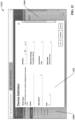
- FIG. 10 is an example development interface 1002 that can be rendered on a client device by the industrial IDE system's user interface component 204.
- Development interface 1002 is organized into panels and workspaces for navigating and editing the system project 302.
- the example interface 1002 depicted in FIG. 10 comprises a main workspace area 1010 that serves as the IDE system's primary work area and an explorer panel 1012 located adjacent to the main workspace area 1010.
- the explorer panel 1012 displays a navigation tree 1006 comprising a hierarchical arrangement of selectable nodes representing elements of the system project 302 being developed.
- selection of a project element from the navigation tree 1006 causes the main workspace area 1010 to render project content corresponding to the selected element, such as ladder logic or other types of control code, program routines, controller tag definitions, device configuration information, or other aspects of the project 302.
- the user can interact with these project elements within the main workspace area 1010 to perform such development functions as writing or editing controller code (e.g., ladder logic, function block diagrams, structured text, etc.), configuring device parameter settings, defining controller tags, or other such project development functions.
- controller code e.g., ladder logic, function block diagrams, structured text, etc.
- FIG. 11 is a view of the explorer panel 1012 and its associated navigation tree 1006 in isolation.
- explorer panel 1012 serves as a means for navigating and viewing content of a system project 302 and supports various ways for performing this navigation.
- Selectable viewing categories are rendered as selectable explorer icons in a control bar 1108 pinned to the left-side edge of the explorer panel 1012. Selection of an explorer icon from the control bar 1108 sets the type of project content to be browsed via the Explorer panel 1012.
- a Devices view icon 1014 has been selected in the control bar 1108, causing the explorer panel 1012 to display, as the navigation tree 1006, a hierarchical arrangement of device nodes 1106 representing the devices defined for the system project 302.
- the device navigation tree 1006 can include a controller node 1102 representing an industrial controller 118 to be programmed as part of the system project 302.
- a backplane node 1104 is defined as a child node of the controller node 1102 and represents the backplane of the industrial controller 118 on which one or more devices or modules will be installed. Any modules or devices to be connected to the controller's backplane are represented as device nodes 1106 below the backplane node 1104.
- Example devices that can be associated with the controller can include, but are not limited to, digital or analog input modules, digital or analog output modules, networking or scanning modules, analytic modules, special function modules, smart industrial devices, motor drives such as variable frequency drives, or other such devices. Per the workflow illustrated in FIG.
- the explorer icons rendered on the control bar 1108 can also include an Application icon that causes the explorer panel 1012 to display a list of applications - e.g., industrial control programs such as ladder logic routines - that make up the system project 302. This viewing mode allows the user to develop, view, and edit control programs within the main workspace area 1010. These control programs will be installed and executed on the industrial controller 118.
- applications e.g., industrial control programs such as ladder logic routines - that make up the system project 302.
- This viewing mode allows the user to develop, view, and edit control programs within the main workspace area 1010.
- These control programs will be installed and executed on the industrial controller 118.
- selecting a device node 1106 in the navigation tree 1006 causes the main workspace area 1010 to display an interactive device configuration interface for viewing and editing configuration parameters for the selected device.
- Device information and configurable device parameters displayed on this device configuration interface are defined by the device profile 906 for the selected device.
- the device configuration interface comprises a main configuration area 1004 and a category window 1008 that lists various informational and configuration categories for the device. Selecting a category from this window 1008 causes the main device configuration area 1004 to render information or configurable device parameters relating to the selected category.
- Informational categories listed in the category window 1008 can include an Overview category and a more detailed Device Information category. Selection of the Overview category can cause summary information about the device - e.g., model number and revision number of the device, device type, a type of electronic keying, or other such information - to be rendered in the main workspace area 1010.
- the user has selected a device node 1106 representing an ethernet bridge module that will be installed on the controller's backplane, and has selected the Overview category within the category window 1008 so that general overview information for the module can be viewed.
- FIG. 12 is a view of the main workspace area 1010 in which a Device Definition editing window 1202 has been invoked for the selected device.
- This window 1202 includes data fields that allow the user to enter or edit various items of information about the device, including but not limited to a name of the device, a description of the device, a controller slot number in which the device is to be installed (if the device is a module to be installed on a controller backplane), revision information, a type of electronic keying, a type of connection, a type of input data, or other such information.
- configuration categories listed in the category window 1008 can include, for example, a Connection category, an Internet Protocol category, a Port Configuration category, a Network category, a Time Sync category, a Display category, a Channels category, a Calibration category, an I/O points category, or other such configuration categories.
- the available configuration categories, as well as the specific parameters that are accessible under each category, can depend on the type of device being viewed. For example, FIG. 13a is a view of the main workspace area 1010 in which the user has selected a 16-point digital input module.
- Available configuration categories listed in the Category window 1008 for this type of device include a Connection category, a Configuration category, and a Points category. The Connection category has been selected in FIG.
- FIG. 13b is a view of the main workspace area 1010 in which the Configuration category has been selected in the Category window 1008. For the selected analog input module, selecting this category causes the configuration area 1004 to display an interactive table that allows the user to set input filter times for groups of input points.
- FIG. 13c is a view of the main workspace area 1010 in which the Points category has been selected in the Category window 1008. This invokes another interactive table in the configuration area 1004 that allows the user to selectively enable or disable changes of state - both on-to-off and off-to-on transitions - for each input point of the module.
- this graphical configuration interface comprises both individual checkbox controls 1302 that allow the user to enable or disable state changes for individual input points, as well as global checkbox controls 1304 that allow the user to enable or disable state changes for all of the module's input points with a single selection input.
- the device configuration interfaces illustrated in FIGs. 10-14c and described above provide an intuitive interface for configuring industrial devices used in the system project 302.
- the device profile library 902 can store device profiles 906 for devices offered by multiple different device vendors, and the IDE system's interface allows these devices to be configured using a common device configuration workflow regardless of device vendor.
- the graphical device configuration interfaces generated by the IDE system 202 offer a more intuitive configuration workflow relative to more generic table-based device configuration interfaces.
- the IDE system 202 can generate the device configuration interfaces using a web-based format, such as hypertext markup language (HTML), allowing the interfaces to be executed on a cloud platform or internet server and served to any type of device that supports web browsing. This format also allows the resulting device configuration interfaces to support a greater degree of customization relative to simple text-based device configuration profiles.
- HTML hypertext markup language
- a developer may wish to apply the same device configuration edits to multiple devices of the same or similar device type. If there are many such devices requiring the same set of device parameter edits, reentering the device parameter modifications for each device can be laborious and time-consuming, even if only a small number of device parameters are to be modified relative to their default values.
- the full set of device parameter values for a device can be saved as a configuration file (e.g., a binary or text file), which can then be applied to other devices.
- a configuration file e.g., a binary or text file
- this approach requires all of the device's configuration parameters to be saved in the configuration file, including those that have not been modified by the user from their default settings. These files must also be created and recorded for each device defined in a project 302. Also, if a set of device parameters are to be replicated across multiple devices having device profiles interfaces of varying formats, it is necessary store versions of the device parameter file that accord to these various formats.
- one or more embodiments of the IDE system 202 can include a device configuration component 210 that stores a custom edit to a device's configuration parameters as a record of the user's sequential interactions with the device profile's graphical interfaces. These recoded interactions can then be reproduced on configuration interfaces of other device profiles for other devices.
- FIG. 15 is a diagram illustrating monitoring and storage of a user's device configuration interactions 1502 as an interaction record 1504 for subsequent playback.
- a user interacts with a device profile configuration interface (such as those illustrated in FIGs. 12-14c ) to edit one or more device parameter values for an industrial device defined in the system project 302.
- These edits are submitted by the user as a sequence of device configuration interactions 1502, such as cursor movements, mouse clicks, and keystrokes used to navigate views of the device configuration interfaces, to select device parameter controls (e.g., checkboxes, data entry fields, drop-down selection boxes, buttons, etc.), and to enter values for selected device parameters.
- the project generation component 206 updates the system project 302 to record the edited device configuration data 1506 based on the user's device configuration interactions 1502.
- the device configuration component 210 monitors and records the user's device configuration interactions 1502 as an interaction record 1504.
- this interaction record 1504 can comprise executable code that, when executed, reproduces the user's device configuration interactions 1502 in the order in which the interactions 1502 were submitted by the user.
- the user may invoke a device profile and modify a single device parameter value for the corresponding device.
- the device configuration interactions 1502 may include moving the cursor to the Category window 1008 of the device profile's configuration interface, selecting a category in this window 1008 to invoke the desired interface in the configuration area 1004, moving the cursor to the control in the configuration area 1004 corresponding to the parameter to be edited, selecting the control, and entering the modified value in the control (e.g., by entering a numeric value or by selecting the value from a drop-down selection box).
- the device configuration component 210 can record all such device configuration interactions 1502 for a given device configuration session, where a device configuration session begins when a user invokes a selected device profile (to begin the session of editing the corresponding device's configuration parameters) and ends when the user closes the device profile's configuration interface, submits or applies the configuration edits (e.g., by selecting an Apply control button), or otherwise indicates that configuration of the device is complete.
- the user can modify any number of device parameters during a configuration session for a given device, and the device configuration component 210 records all device configuration interactions 1502 submitted by the user during the configuration session.
- the resulting interaction record 1504 can comprise any suitable file or object format capable of reproducing the device configuration interactions 1502 when executed.
- the device configuration component 210 can store the interaction record 1504 as an automation object 222 representing the device configuration, or as a property of an automation object 222 representing the device itself.
- the automation object 222 and its associated interaction record 1504 can then be stored in the automation object library 502 as a reusable object that can be applied to other device instances within the system project 302.
- the interaction record 1504 can also be encapsulated and stored in other ways without departing from the scope of one or more embodiments.
- FIG. 16 is a diagram illustrating selective application of a stored interaction record 1504 to another device profile.
- the record 1504 becomes available for selective application to other device profiles within a system project 302. If the user wishes to apply the same device parameter edits that yielded the interaction record 1504 to a second device defined within the system project 302, the user can select the automation object 222 that defines the interaction record 1504 and apply the interaction record 1504 to the device profile 906 corresponding to the second device.
- This approach for storing device configuration edits and applying the edits to other devices has advantages relative to storing modified text or binary files containing all of the device's configuration parameters.
- the interaction record 1504 will typically have a smaller size relative to a text file containing all of the parameters - both edited and unedited - for a given device.
- this approach ensures that other device parameters of the target device maintain their original values rather than being overwritten by another device's corresponding default parameter values. This approach also mitigates the need to maintain multiple different formats of a configuration file to accommodate device profiles having different formats.
- the interaction record 1504 defines the device parameter edits in terms of a first user's interactions with graphical device profile interfaces, a second user can apply these interactions to another device even if the second user has no knowledge of where the device parameters to be edited are located within the graphical device profile interfaces.
- This approach also saves considerable development time and effort relative to manually entering the same parameter edit on multiple device profiles.
- this approach to propagating device configuration edits to multiple devices leverages the graphical device configuration workflow made possible by the device profiles 906.
- the device configuration component 210 can also apply a security layer to interaction records 1504 so that the device configuration interactions 1502 are locked into an encrypted interaction record 1504. In such embodiments, the device configuration component 210 can permit selection and execution of the interaction record 1504 only if the user invoking the record 1504 has submitted suitable authentication credentials for the project editing session.
- some embodiments of the device configuration component 210 can support the use of artificial intelligence to generate the interaction record 1504 for a given device editing session or to execute the interaction record 1504 on another device profile 906. For example, if an interaction record 1504 that was generated based on device configuration interactions 1502 with a first graphical interface of a first device profile is subsequently applied to a second graphical interface of a second device profile, and an edited device parameter is positioned at a different location on the second graphical interface relative to its location on the first graphical interface, the device configuration component 210 can use artificial intelligence or machine learning to infer that the parameter on the second interface corresponds to the edited parameter of the first interface despite the different locations. Artificial intelligence can also be used in connection with generating the interaction record 1504 in some embodiments.
- the device configuration component 210 can infer that a user's device configuration interactions 1502 include unnecessary steps - e.g., superfluous cursor movements, graphical element selections, or keystrokes - and eliminate these unnecessary steps from the interaction record 1504 so that only those interactions necessary to implement the device parameter modifications are recorded.
- unnecessary steps - e.g., superfluous cursor movements, graphical element selections, or keystrokes -
- the industrial device configuration features described herein can allow an edit to one or more device parameters of a first device profile to be easily and quickly applied to other device profiles without the need to manually re-enter the edits and without requiring storage of a device configuration file that records all of the device's parameter values.
- Each reusable interaction record 1504 can be applied to a selected device profile to facilitate duplicating a set of edits on that profile without requiring the user to have knowledge of the locations of the device parameters being edited.
- the interaction records 1504 can be stored in an IDE system library as a selectable design object that can be applied as needed to device instances defined in an industrial system project 302.
- FIGs. 17a-17b illustrate a methodology in accordance with one or more embodiments of the subject application. While, for purposes of simplicity of explanation, the methodology shown herein are shown and described as a series of acts, it is to be understood and appreciated that the subject innovation is not limited by the order of acts, as some acts may, in accordance therewith, occur in a different order and/or concurrently with other acts from that shown and described herein. For example, those skilled in the art will understand and appreciate that a methodology could alternatively be represented as a series of interrelated states or events, such as in a state diagram. Moreover, not all illustrated acts may be required to implement a methodology in accordance with the innovation.
- interaction diagram(s) may represent methodologies, or methods, in accordance with the subject disclosure when disparate entities enact disparate portions of the methodologies.
- two or more of the disclosed example methods can be implemented in combination with each other, to accomplish one or more features or advantages described herein.
- FIG. 17a illustrates a first part of an example methodology 1700a for applying a device parameter edit made to a first device to one or more second devices within an industrial IDE environment.
- a device configuration interface defined by a first device profile is rendered by an industrial IDE system.
- the first device profile corresponds to a type of industrial device and defines graphical interface displays for viewing and editing values of configuration parameters for the device type.
- the device configuration interface comprises graphical controls - e.g., data entry fields, checkboxes, drop-down selection boxes, buttons, etc. - for setting values of configuration parameters for an industrial device defined in a control project being developed within the IDE system's development environment.
- monitoring and recording of user interactions with the device configuration interface is initiated.
- This step monitors such user interactions as cursor movements, selection actions (e.g., mouse clicks), keystrokes, text highlighting, or other such interactions with the device configuration interface. These interactions can represent the user's actions in connection with navigating to, selecting, and editing one or more configuration parameters for an instance of the device type corresponding to the first device profile.
- step 1710 the methodology proceeds to step 1712, where the interaction record is stored in a library associated with the industrial IDE system.
- the interaction record defines the sequence of user interactions in the order in which they occurred and can be stored as a reusable object or file that can be selectively applied to device configuration interfaces defined by other device profiles.
- the methodology then proceeds to the second part illustrated in FIG. 17b .
- a determination is made as to whether an instruction to apply the interaction record to a second device profile is received. If such an instruction is received (YES at step 1714), the methodology proceeds to step 1716, where the user interactions recorded in the interaction record are executed on a device configuration interface defined by the second device profile, thereby reproducing, on the second device profile, the device parameter edits that were manually applied to the first device profile.
- Embodiments, systems, and components described herein, as well as control systems and automation environments in which various aspects set forth in the subject specification can be carried out can include computer or network components such as servers, clients, programmable logic controllers (PLCs), automation controllers, communications modules, mobile computers, on-board computers for mobile vehicles, wireless components, control components and so forth which are capable of interacting across a network.
- Computers and servers include one or more processors-electronic integrated circuits that perform logic operations employing electric signals-configured to execute instructions stored in media such as random access memory (RAM), read only memory (ROM), a hard drives, as well as removable memory devices, which can include memory sticks, memory cards, flash drives, external hard drives, and so on.
- the term PLC or automation controller as used herein can include functionality that can be shared across multiple components, systems, and/or networks.
- one or more PLCs or automation controllers can communicate and cooperate with various network devices across the network. This can include substantially any type of control, communications module, computer, Input/Output (I/O) device, sensor, actuator, and human machine interface (HMI) that communicate via the network, which includes control, automation, and/or public networks.
- the PLC or automation controller can also communicate to and control various other devices such as standard or safety-rated I/O modules including analog, digital, programmed/intelligent I/O modules, other programmable controllers, communications modules, sensors, actuators, output devices, and the like.
- the network can include public networks such as the internet, intranets, and automation networks such as control and information protocol (CIP) networks including DeviceNet, ControlNet, safety networks, and Ethernet/IP. Other networks include Ethernet, DH/DH+, Remote I/O, Fieldbus, Modbus, Profibus, CAN, wireless networks, serial protocols, and so forth.
- the network devices can include various possibilities (hardware and/or software components). These include components such as switches with virtual local area network (VLAN) capability, LANs, WANs, proxies, gateways, routers, firewalls, virtual private network (VPN) devices, servers, clients, computers, configuration tools, monitoring tools, and/or other devices.
- VLAN virtual local area network
- WANs wide area network
- proxies gateways
- routers virtual private network
- VPN virtual private network
- FIGs. 18 and 19 are intended to provide a brief, general description of a suitable environment in which the various aspects of the disclosed subject matter may be implemented. While the embodiments have been described above in the general context of computer-executable instructions that can run on one or more computers, those skilled in the art will recognize that the embodiments can be also implemented in combination with other program modules and/or as a combination of hardware and software.
- program modules include routines, programs, components, data structures, etc., that perform particular tasks or implement particular abstract data types.
- inventive methods can be practiced with other computer system configurations, including single-processor or multiprocessor computer systems, minicomputers, mainframe computers, Internet of Things (IoT) devices, distributed computing systems, as well as personal computers, hand-held computing devices, microprocessor-based or programmable consumer electronics, and the like, each of which can be operatively coupled to one or more associated devices.
- IoT Internet of Things
- the illustrated embodiments herein can be also practiced in distributed computing environments where certain tasks are performed by remote processing devices that are linked through a communications network.
- program modules can be located in both local and remote memory storage devices.
- Computer-readable storage media can include, but are not limited to, random access memory (RAM), read only memory (ROM), electrically erasable programmable read only memory (EEPROM), flash memory or other memory technology, compact disk read only memory (CD-ROM), digital versatile disk (DVD), Blu-ray disc (BD) or other optical disk storage, magnetic cassettes, magnetic tape, magnetic disk storage or other magnetic storage devices, solid state drives or other solid state storage devices, or other tangible and/or non-transitory media which can be used to store desired information.
- RAM random access memory
- ROM read only memory
- EEPROM electrically erasable programmable read only memory
- flash memory or other memory technology
- CD-ROM compact disk read only memory
- DVD digital versatile disk
- Blu-ray disc (BD) or other optical disk storage magnetic cassettes, magnetic tape, magnetic disk storage or other magnetic storage devices, solid state drives or other solid state storage devices, or other tangible and/or non-transitory media which can be used to store desired information.
- Computer-readable storage media can be accessed by one or more local or remote computing devices, e.g., via access requests, queries or other data retrieval protocols, for a variety of operations with respect to the information stored by the medium.
- Communications media typically embody computer-readable instructions, data structures, program modules or other structured or unstructured data in a data signal such as a modulated data signal, e.g., a carrier wave or other transport mechanism, and includes any information delivery or transport media.
- modulated data signal or signals refers to a signal that has one or more of its characteristics set or changed in such a manner as to encode information in one or more signals.
- communication media include wired media, such as a wired network or direct-wired connection, and wireless media such as acoustic, RF, infrared and other wireless media.
- the example environment 1800 for implementing various embodiments of the aspects described herein includes a computer 1802, the computer 1802 including a processing unit 1804, a system memory 1806 and a system bus 1808.
- the system bus 1808 couples system components including, but not limited to, the system memory 1806 to the processing unit 1804.
- the processing unit 1804 can be any of various commercially available processors. Dual microprocessors and other multi-processor architectures can also be employed as the processing unit 1804.
- the system bus 1808 can be any of several types of bus structure that can further interconnect to a memory bus (with or without a memory controller), a peripheral bus, and a local bus using any of a variety of commercially available bus architectures.
- the system memory 1806 includes ROM 1810 and RAM 1812.
- a basic input/output system (BIOS) can be stored in a non-volatile memory such as ROM, erasable programmable read only memory (EPROM), EEPROM, which BIOS contains the basic routines that help to transfer information between elements within the computer 1802, such as during startup.
- the RAM 1812 can also include a highspeed RAM such as static RAM for caching data.
- the computer 1802 further includes an internal hard disk drive (HDD) 1814 (e.g., EIDE, SATA), one or more external storage devices 1816 (e.g., a magnetic floppy disk drive (FDD) 1816, a memory stick or flash drive reader, a memory card reader, etc.) and an optical disk drive 1820 (e.g., which can read or write from a CD-ROM disc, a DVD, a BD, etc.).
- HDD 1814 e.g., EIDE, SATA
- external storage devices 1816 e.g., a magnetic floppy disk drive (FDD) 1816, a memory stick or flash drive reader, a memory card reader, etc.
- an optical disk drive 1820 e.g., which can read or write from a CD-ROM disc, a DVD, a BD, etc.
- the internal HDD 1814 is illustrated as located within the computer 1802, the internal HDD 1814 can also be configured for external use in a suitable chassis (not shown).
- the HDD 1814, external storage device(s) 1816 and optical disk drive 1820 can be connected to the system bus 1808 by an HDD interface 1824, an external storage interface 1826 and an optical drive interface 1828, respectively.
- the interface 1824 for external drive implementations can include at least one or both of Universal Serial Bus (USB) and Institute of Electrical and Electronics Engineers (IEEE) 1394 interface technologies. Other external drive connection technologies are within contemplation of the embodiments described herein.
- the drives and their associated computer-readable storage media provide nonvolatile storage of data, data structures, computer-executable instructions, and so forth.
- the drives and storage media accommodate the storage of any data in a suitable digital format.
- computer-readable storage media refers to respective types of storage devices, it should be appreciated by those skilled in the art that other types of storage media which are readable by a computer, whether presently existing or developed in the future, could also be used in the example operating environment, and further, that any such storage media can contain computer-executable instructions for performing the methods described herein.
- a number of program modules can be stored in the drives and RAM 1812, including an operating system 1830, one or more application programs 1832, other program modules 1834 and program data 1836. All or portions of the operating system, applications, modules, and/or data can also be cached in the RAM 1812.
- the systems and methods described herein can be implemented utilizing various commercially available operating systems or combinations of operating systems.
- the computer 1802 can operate in a networked environment using logical connections via wired and/or wireless communications to one or more remote computers, such as a remote computer(s) 1848.
- the remote computer(s) 1848 can be a workstation, a server computer, a router, a personal computer, portable computer, microprocessor-based entertainment appliance, a peer device or other common network node, and typically includes many or all of the elements described relative to the computer 1802, although, for purposes of brevity, only a memory/storage device 1850 is illustrated.
- the logical connections depicted include wired/wireless connectivity to a local area network (LAN) 1852 and/or larger networks, e.g., a wide area network (WAN) 1854.
- LAN and WAN networking environments are commonplace in offices and companies, and facilitate enterprise-wide computer networks, such as intranets, all of which can connect to a global communications network, e.g., the Internet.
- the computer 1802 can include a modem 1858 or can be connected to a communications server on the WAN 1854 via other means for establishing communications over the WAN 1854, such as by way of the Internet.
- the modem 1858 which can be internal or external and a wired or wireless device, can be connected to the system bus 1808 via the input device interface 1822.
- program modules depicted relative to the computer 1802 or portions thereof can be stored in the remote memory/storage device 1850. It will be appreciated that the network connections shown are example and other means of establishing a communications link between the computers can be used.
Landscapes
- Engineering & Computer Science (AREA)
- Physics & Mathematics (AREA)
- General Physics & Mathematics (AREA)
- Automation & Control Theory (AREA)
- Human Computer Interaction (AREA)
- Manufacturing & Machinery (AREA)
- User Interface Of Digital Computer (AREA)
- Programmable Controllers (AREA)
Applications Claiming Priority (1)
| Application Number | Priority Date | Filing Date | Title |
|---|---|---|---|
| US17/846,165 US20230418263A1 (en) | 2022-06-22 | 2022-06-22 | Device configuration object template with user interaction for device properties generator |
Publications (1)
| Publication Number | Publication Date |
|---|---|
| EP4296803A1 true EP4296803A1 (de) | 2023-12-27 |
Family
ID=86603930
Family Applications (1)
| Application Number | Title | Priority Date | Filing Date |
|---|---|---|---|
| EP23175064.7A Pending EP4296803A1 (de) | 2022-06-22 | 2023-05-24 | Vorrichtungskonfigurationsobjektvorlage mit benutzerinteraktion für vorrichtungseigenschaftsgenerator |
Country Status (2)
| Country | Link |
|---|---|
| US (1) | US20230418263A1 (de) |
| EP (1) | EP4296803A1 (de) |
Citations (2)
| Publication number | Priority date | Publication date | Assignee | Title |
|---|---|---|---|---|
| US20180088564A1 (en) * | 2016-09-26 | 2018-03-29 | Rockwell Automation Technologies, Inc. | Workflow tracking and identification using an industrial monitoring system |
| EP3009900B1 (de) * | 2014-10-13 | 2020-01-22 | Siemens Aktiengesellschaft | Dynamische Empfehlung von zur Verwendung in einer technischen Konfiguration geeigneten Elementen |
-
2022
- 2022-06-22 US US17/846,165 patent/US20230418263A1/en active Pending
-
2023
- 2023-05-24 EP EP23175064.7A patent/EP4296803A1/de active Pending
Patent Citations (2)
| Publication number | Priority date | Publication date | Assignee | Title |
|---|---|---|---|---|
| EP3009900B1 (de) * | 2014-10-13 | 2020-01-22 | Siemens Aktiengesellschaft | Dynamische Empfehlung von zur Verwendung in einer technischen Konfiguration geeigneten Elementen |
| US20180088564A1 (en) * | 2016-09-26 | 2018-03-29 | Rockwell Automation Technologies, Inc. | Workflow tracking and identification using an industrial monitoring system |
Also Published As
| Publication number | Publication date |
|---|---|
| US20230418263A1 (en) | 2023-12-28 |
Similar Documents
| Publication | Publication Date | Title |
|---|---|---|
| US11669309B2 (en) | Extensible integrated development environment (IDE) platform with open application programming interfaces (APIs) | |
| US11481313B2 (en) | Testing framework for automation objects | |
| US11947943B2 (en) | Industrial automation smart object inheritance | |
| US11733977B2 (en) | Graphical and text based co-design editor for industrial automation projects | |
| EP4137937A1 (de) | Gemeinsame nutzung einer projektbibliothek für die industrielle automatisierung | |
| EP4296848A1 (de) | System und verfahren zur vorrichtungsprofilerzeugung in einer integrierten entwicklungsumgebung | |
| US20230152790A1 (en) | System model smart object configuration | |
| EP4057086A1 (de) | Intelligente objektvererbung für die industrieautomatisierung und singleton-erzeugung | |
| EP4296803A1 (de) | Vorrichtungskonfigurationsobjektvorlage mit benutzerinteraktion für vorrichtungseigenschaftsgenerator | |
| US20240103850A1 (en) | Presentation design to background service binding | |
| US20240103851A1 (en) | Presentation design to automation device binding | |
| US20240103852A1 (en) | Presentation design dynamic generation from data model server | |
| US20240019850A1 (en) | Extensible profiles for industrial control modules | |
| US20240086182A1 (en) | Method for connecting a web socket session with an object instance with automation device association | |
| US11835941B2 (en) | Industrial automation smart object parent/child data collection propagation | |
| US11972257B2 (en) | Industrial automation system topology with point to point business rule integration | |
| EP4307104A1 (de) | Erweiterbare profile für industrielle steuergeräte |
Legal Events
| Date | Code | Title | Description |
|---|---|---|---|
| PUAI | Public reference made under article 153(3) epc to a published international application that has entered the european phase |
Free format text: ORIGINAL CODE: 0009012 |
|
| STAA | Information on the status of an ep patent application or granted ep patent |
Free format text: STATUS: THE APPLICATION HAS BEEN PUBLISHED |
|
| AK | Designated contracting states |
Kind code of ref document: A1 Designated state(s): AL AT BE BG CH CY CZ DE DK EE ES FI FR GB GR HR HU IE IS IT LI LT LU LV MC ME MK MT NL NO PL PT RO RS SE SI SK SM TR |