EP4296785A1 - Information processing device and program - Google Patents
Information processing device and program Download PDFInfo
- Publication number
- EP4296785A1 EP4296785A1 EP22756099.2A EP22756099A EP4296785A1 EP 4296785 A1 EP4296785 A1 EP 4296785A1 EP 22756099 A EP22756099 A EP 22756099A EP 4296785 A1 EP4296785 A1 EP 4296785A1
- Authority
- EP
- European Patent Office
- Prior art keywords
- screen
- display
- processing device
- information processing
- setting screen
- Prior art date
- Legal status (The legal status is an assumption and is not a legal conclusion. Google has not performed a legal analysis and makes no representation as to the accuracy of the status listed.)
- Pending
Links
Images






Classifications
-
- G—PHYSICS
- G06—COMPUTING OR CALCULATING; COUNTING
- G06F—ELECTRIC DIGITAL DATA PROCESSING
- G06F3/00—Input arrangements for transferring data to be processed into a form capable of being handled by the computer; Output arrangements for transferring data from processing unit to output unit, e.g. interface arrangements
- G06F3/01—Input arrangements or combined input and output arrangements for interaction between user and computer
- G06F3/048—Interaction techniques based on graphical user interfaces [GUI]
- G06F3/0484—Interaction techniques based on graphical user interfaces [GUI] for the control of specific functions or operations, e.g. selecting or manipulating an object, an image or a displayed text element, setting a parameter value or selecting a range
- G06F3/04845—Interaction techniques based on graphical user interfaces [GUI] for the control of specific functions or operations, e.g. selecting or manipulating an object, an image or a displayed text element, setting a parameter value or selecting a range for image manipulation, e.g. dragging, rotation, expansion or change of colour
-
- G—PHYSICS
- G03—PHOTOGRAPHY; CINEMATOGRAPHY; ANALOGOUS TECHNIQUES USING WAVES OTHER THAN OPTICAL WAVES; ELECTROGRAPHY; HOLOGRAPHY
- G03G—ELECTROGRAPHY; ELECTROPHOTOGRAPHY; MAGNETOGRAPHY
- G03G15/00—Apparatus for electrographic processes using a charge pattern
- G03G15/50—Machine control of apparatus for electrographic processes using a charge pattern, e.g. regulating differents parts of the machine, multimode copiers, microprocessor control
- G03G15/5075—Remote control machines, e.g. by a host
- G03G15/5079—Remote control machines, e.g. by a host for maintenance
-
- G—PHYSICS
- G06—COMPUTING OR CALCULATING; COUNTING
- G06F—ELECTRIC DIGITAL DATA PROCESSING
- G06F3/00—Input arrangements for transferring data to be processed into a form capable of being handled by the computer; Output arrangements for transferring data from processing unit to output unit, e.g. interface arrangements
- G06F3/01—Input arrangements or combined input and output arrangements for interaction between user and computer
- G06F3/048—Interaction techniques based on graphical user interfaces [GUI]
- G06F3/0481—Interaction techniques based on graphical user interfaces [GUI] based on specific properties of the displayed interaction object or a metaphor-based environment, e.g. interaction with desktop elements like windows or icons, or assisted by a cursor's changing behaviour or appearance
-
- G—PHYSICS
- G06—COMPUTING OR CALCULATING; COUNTING
- G06F—ELECTRIC DIGITAL DATA PROCESSING
- G06F3/00—Input arrangements for transferring data to be processed into a form capable of being handled by the computer; Output arrangements for transferring data from processing unit to output unit, e.g. interface arrangements
- G06F3/01—Input arrangements or combined input and output arrangements for interaction between user and computer
- G06F3/048—Interaction techniques based on graphical user interfaces [GUI]
- G06F3/0481—Interaction techniques based on graphical user interfaces [GUI] based on specific properties of the displayed interaction object or a metaphor-based environment, e.g. interaction with desktop elements like windows or icons, or assisted by a cursor's changing behaviour or appearance
- G06F3/0483—Interaction with page-structured environments, e.g. book metaphor
-
- G—PHYSICS
- G06—COMPUTING OR CALCULATING; COUNTING
- G06F—ELECTRIC DIGITAL DATA PROCESSING
- G06F3/00—Input arrangements for transferring data to be processed into a form capable of being handled by the computer; Output arrangements for transferring data from processing unit to output unit, e.g. interface arrangements
- G06F3/01—Input arrangements or combined input and output arrangements for interaction between user and computer
- G06F3/048—Interaction techniques based on graphical user interfaces [GUI]
- G06F3/0487—Interaction techniques based on graphical user interfaces [GUI] using specific features provided by the input device, e.g. functions controlled by the rotation of a mouse with dual sensing arrangements, or of the nature of the input device, e.g. tap gestures based on pressure sensed by a digitiser
- G06F3/0488—Interaction techniques based on graphical user interfaces [GUI] using specific features provided by the input device, e.g. functions controlled by the rotation of a mouse with dual sensing arrangements, or of the nature of the input device, e.g. tap gestures based on pressure sensed by a digitiser using a touch-screen or digitiser, e.g. input of commands through traced gestures
-
- H—ELECTRICITY
- H04—ELECTRIC COMMUNICATION TECHNIQUE
- H04N—PICTORIAL COMMUNICATION, e.g. TELEVISION
- H04N1/00—Scanning, transmission or reproduction of documents or the like, e.g. facsimile transmission; Details thereof
- H04N1/0035—User-machine interface; Control console
- H04N1/00405—Output means
- H04N1/00408—Display of information to the user, e.g. menus
- H04N1/00411—Display of information to the user, e.g. menus the display also being used for user input, e.g. touch screen
-
- H—ELECTRICITY
- H04—ELECTRIC COMMUNICATION TECHNIQUE
- H04N—PICTORIAL COMMUNICATION, e.g. TELEVISION
- H04N1/00—Scanning, transmission or reproduction of documents or the like, e.g. facsimile transmission; Details thereof
- H04N1/0035—User-machine interface; Control console
- H04N1/00405—Output means
- H04N1/00408—Display of information to the user, e.g. menus
- H04N1/00469—Display of information to the user, e.g. menus with enlargement of a selected area of the displayed information
-
- H—ELECTRICITY
- H04—ELECTRIC COMMUNICATION TECHNIQUE
- H04N—PICTORIAL COMMUNICATION, e.g. TELEVISION
- H04N1/00—Scanning, transmission or reproduction of documents or the like, e.g. facsimile transmission; Details thereof
- H04N1/0035—User-machine interface; Control console
- H04N1/00501—Tailoring a user interface [UI] to specific requirements
- H04N1/00506—Customising to the data to be displayed
-
- G—PHYSICS
- G03—PHOTOGRAPHY; CINEMATOGRAPHY; ANALOGOUS TECHNIQUES USING WAVES OTHER THAN OPTICAL WAVES; ELECTROGRAPHY; HOLOGRAPHY
- G03G—ELECTROGRAPHY; ELECTROPHOTOGRAPHY; MAGNETOGRAPHY
- G03G15/00—Apparatus for electrographic processes using a charge pattern
- G03G15/50—Machine control of apparatus for electrographic processes using a charge pattern, e.g. regulating differents parts of the machine, multimode copiers, microprocessor control
- G03G15/5016—User-machine interface; Display panels; Control console
- G03G15/502—User-machine interface; Display panels; Control console relating to the structure of the control menu, e.g. pop-up menus, help screens
-
- H—ELECTRICITY
- H04—ELECTRIC COMMUNICATION TECHNIQUE
- H04N—PICTORIAL COMMUNICATION, e.g. TELEVISION
- H04N1/00—Scanning, transmission or reproduction of documents or the like, e.g. facsimile transmission; Details thereof
- H04N1/0035—User-machine interface; Control console
- H04N1/00405—Output means
- H04N1/00408—Display of information to the user, e.g. menus
- H04N1/00472—Display of information to the user, e.g. menus using a pop-up window
-
- H—ELECTRICITY
- H04—ELECTRIC COMMUNICATION TECHNIQUE
- H04N—PICTORIAL COMMUNICATION, e.g. TELEVISION
- H04N1/00—Scanning, transmission or reproduction of documents or the like, e.g. facsimile transmission; Details thereof
- H04N1/0035—User-machine interface; Control console
- H04N1/00405—Output means
- H04N1/00477—Indicating status, e.g. of a job
Definitions
- the present disclosure relates to an information processing device and a program.
- JP-A No. 2006-107301 discloses an extension control device that can always display and operate a keyboard display button without changing the size, display method, or the like of other data such as a displayed window or text, or changing the position.
- JP-A No. 2011-188105 discloses an image forming apparatus capable of displaying a preview in parallel with reading processing and capable of notifying an error during the preview display.
- JP-A No. 2015-132931 discloses an information processing device capable of displaying input information on a screen on which the information is to be displayed among a plurality of screens provided from an application.
- an operation screen is configured by a touch panel, for example, a second screen such as a setting screen is displayed in superposition with a first screen such as a main menu screen.
- a second screen such as a setting screen is displayed in superposition with a first screen such as a main menu screen.
- the change in the display content occurring in the first screen is blocked by the second screen, and there is a possibility that the user does not notice the occurrence of such an event.
- An object of the present disclosure is to provide an information processing device and a program that enable a user to grasp occurrence of an event that changes the display content of the first screen even when the second screen is superimposed and displayed on the first screen.
- an information processing device including: a processor, in which the processor configured to cause display of a second screen, which is different from a first screen displayed on an operation screen, superimposed on at least a part of the first screen as a result of accepting an operation of a user, and change a display mode of the second screen such that a change in display content occurring on the first screen becomes visible in a case in which display content of the first screen changes.
- the processor is configured to cause display of the second screen so as to cover the first screen with the second screen by gradually enlarging a display area of the second screen, as a result of accepting the operation of the user.
- the processor is configured to cause display of the second screen so as to cover the first screen with the second screen by gradually enlarging the display area of the second screen, as a result of accepting a swipe operation of the user.
- the processor is configured to change the display mode of the second screen by gradually reducing the display area of the second screen in a case in which the display content of the first screen changes.
- the processor is configured to change the display mode of the second screen such that a change in display content occurring on the first screen becomes visible in a case in which an operation input on the second screen is no longer accepted due to occurrence of the event.
- the processor is configured not to change a display mode of the second screen in a case in which an operation input on the second screen can be received even when the event occurs.
- a program executable by a computer to perform processing comprising: causing display of a second screen, which is different from a first screen displayed on an operation screen, superimposed on at least a part of the first screen as a result of accepting an operation of a user, and changing a display mode of the second screen such that a change in display content occurring on the first screen becomes visible in a case in which display content of the first screen changes.
- the user can grasp the occurrence of the event that changes the display content of the first screen.
- the user can visually grasp that the second screen is displayed in a superimposed manner on the first screen.
- the user can visually grasp that the second screen is displayed in a superimposed manner on the first screen.
- the user can visually grasp that the second screen displayed in a superimposed manner on the first screen is shifted from the top of the first screen.
- the information processing device of the fifth aspect of the disclosure it is possible to prevent occurrence of a situation in which the second screen disappears when the user is performing an operation input to the second screen.
- the information processing device of the sixth aspect of the disclosure it is possible to prevent occurrence of a situation in which the second screen disappears when the user is performing an operation input to the second screen.
- the user can grasp the occurrence of an event that changes the display content of the first screen.
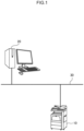
- Fig. 1 is a diagram illustrating a system configuration of an image forming system according to a first embodiment
- the image forming system of the present embodiment includes an image forming apparatus 10 and a terminal device 20 connected to each other by a network 30.
- the terminal device 20 generates print data and transmits the generated print data to the image forming apparatus 10 via the network 30.
- the image forming apparatus 10 receives print data transmitted from the terminal device 20 and outputs an image corresponding to the print data on a sheet.
- the image forming apparatus 10 is a so-called multi-function machine having a plurality of functions such as a printing function, a scanning function, a copying function, and a facsimile function.
- the image forming apparatus 10 is an example of an information processing device in the technology of the disclosure.
- FIG. 2 a hardware configuration of the image forming apparatus 10 in the image forming system of the present embodiment is illustrated in Fig. 2 .
- the image forming apparatus 10 includes a central processing unit (CPU) 11, a memory 12, a storage device 13 such as a hard disk drive, a communication interface (abbreviated as IF) 14 that transmits and receives data to and from an external device or the like via the network 30, a user interface (abbreviated as UI) device 15 including a touch panel or a liquid crystal display and a keyboard, a scanner 16, and a print engine 17. These components are connected to each other via a control bus 18.
- CPU central processing unit
- IF communication interface
- UI user interface
- the print engine 17 prints an image on a recording medium such as printing paper through processes such as charging, exposure, development, transfer, and fixing.
- the CPU 11 is a processor that executes predetermined processing based on a control program stored in the memory 12 or the storage device 13 to control the operation of the image forming apparatus 10.
- the CPU 11 is described as reading and executing a control program stored in the memory 12 or the storage device 13, but the program may be stored in a storage medium such as a compact disc read only memory (CD-ROM) and provided to the CPU 11.
- CD-ROM compact disc read only memory
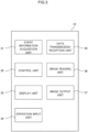
- Fig. 3 is a block diagram illustrating a functional configuration of the image forming apparatus 10 realized by executing the control program.
- the image forming apparatus 10 of the present embodiment includes an event information acquisition unit 31, a control unit 32, a display unit 33, an operation input unit 34, a data transmission/reception unit 35, an image reading unit 36, and an image output unit 37.
- the display unit 33 is controlled by the control unit 32 and displays various types of information to the user.
- the operation input unit 34 inputs various operation information performed by the user.
- the data transmission/reception unit 35 transmits and receives data to and from an external device such as the terminal device 20.
- the image reading unit 36 reads a document image from a set document under the control of the control unit 32.
- the image output unit 37 outputs an image on a recording medium such as printing paper under the control of the control unit 32.
- the control unit 32 controls the overall operation of the image forming apparatus 10, generates print data based on a print job received from the terminal device 20 via the data transmission/reception unit 35, and performs control to output the generated print data from the image output unit 37 and control to read a document image by the image reading unit 36, and the like.
- the event information acquisition unit 31 acquires event information that has occurred in the image forming apparatus 10.
- the event information is information on some event related to the image forming apparatus 10, and includes, for example, information on a plurality of systems such as information on an abnormality relationship, information on an external operation relationship, and information on a login relationship.
- Examples of the information on the abnormality relationship include information indicating a failure of the image forming apparatus 10, information indicating that a door of a housing of the image forming apparatus 10 is opened, and information indicating that an executing job has failed.
- Examples of the information on the external operation relationship include information indicating that the setting of the image forming apparatus 10 has been changed from the terminal device 20, information indicating that software is being installed in the image forming apparatus 10, and the like.
- Examples of the information on the login relationship include information indicating that a card for performing user authentication has been detected in a card reader provided in the image forming apparatus 10, information indicating that money has been deposited or returned in a billing apparatus provided in the image forming apparatus 10, and the like.
- the control unit 32 displays a home screen and a setting screen different from the home screen as operation screens on an operation panel provided in the image forming apparatus 10.
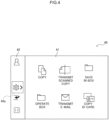
- Fig. 4 is a display example of a home screen display state which is an example of the operation screen 40 displayed on the operation panel.
- Fig. 5 is a diagram illustrating a hierarchical structure of the operation screen 40 in the home screen display state.
- the operation screen 40 has a two-layer structure of a home screen 41 and a setting screen 42, and the setting screen 42 is displayed in a superimposed manner on the home screen 41.
- the home screen 41 is provided with icons for inputting instructions for various jobs such as copy and transmission of a scanned copy.
- the setting screen 42 is displayed in a reduced state that is displayed only in a partial region at the left end of the operation screen 40.
- the setting screen 42 in the reduced state is provided with an icon and the like commonly used in the home screen display state and the setting screen display state, in addition to an enlargement icon 42a for enlarging the setting screen 42.
- the entire area of the home screen 41 is displayed, and the setting screen 42 in the reduced state is displayed on the left side of the home screen 41.
- the control unit 32 accepts the operation of the user to display the setting screen 42 in a superimposed manner on at least a part of the home screen 41 displayed on the operation screen 40, thereby bringing the operation screen 40 into the setting screen display state.
- the setting screen 42 may be displayed in a superimposed manner so as to cover the home screen 41 with the setting screen 42 by gradually enlarging the display area of the setting screen by accepting the operation of the user, and the operation screen 40 may be set to the setting screen display state.
- the operation of the user for bringing the operation screen 40 into the setting screen display state may be, for example, a swipe operation of the user.
- Fig. 6 is a diagram for explaining switching from the home screen display state to the setting screen display state by the swipe operation.
- the operation screen 40 When the operation screen 40 is in the home screen display state, as illustrated in Fig. 6A , the user touches the enlargement icon 42a on the setting screen 42, and performs a swipe operation toward the right side in a state of touching the enlargement icon 42a.
- the home screen 41 is gradually covered with the setting screen 42, and the display area of the setting screen 42 is gradually enlarged.
- the state becomes the setting screen display state in which the setting screen 42 is displayed on the entire operation screen 40.
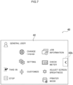
- Fig. 7 is a display example of a setting screen display state which is an example of the operation screen 40 displayed on the operation panel.
- Fig. 8 is a diagram illustrating the hierarchical structure of the operation screen 40 in the setting screen display state.
- the setting screen 42 is displayed in an enlarged state displayed in the entire area of the operation screen 40.
- the setting screen 42 in the enlarged state is provided with, in addition to a reduction icon 42b for reducing the setting screen 42, icons to be commonly used in the home screen display state and the setting screen display state, icons for performing various settings such as language switching and customization, and the like.
- Fig. 9 is a display example of the event information displayed on the home screen 41.
- the control unit 32 displays an event display window 41a at the center of the home screen 41 and updates the display of the home screen 41.
- the control unit 32 changes the display mode of the setting screen 42 so that the change in the display content that has occurred on the home screen 41 becomes visible, thereby changing the operation screen 40 from the setting screen display state to the home screen display state, and displaying the event display window 41a on the home screen 41.
- the control unit 32 displays the event display window 41a indicating a failure of the image forming apparatus 10 at the center of the home screen 41 and updates the display of the home screen 41 as illustrated in Fig. 9 .
- the setting screen 42 may be brought into a reduced state and the operation screen 40 may be brought into a home screen display state.
- Fig. 10 is a diagram for explaining switching from the setting screen display state to the home screen display state.
- the control unit 32 When detecting that an event that the display of the home screen 41 changes occurs in a state where the operation screen 40 is in the setting screen display state as illustrated in Fig. 10A , the control unit 32 gradually reduces the display area of the setting screen 42 as illustrated in Fig. 10B .
- the control unit 32 brings the operation screen 40 into the home screen display state, displays the entire area of the home screen 41 on the operation screen 40, and allows the user to visually recognize the event display window 41a.
- Step S101 the control unit 32 detects occurrence of an event in which the display of the home screen 41 changes.
- Step S102 the control unit 32 determines whether or not the operation screen 40 is in the setting screen display state.
- Step S102 In a case in which it is determined in Step S102 that the operation screen is not in the setting screen display state, that is, the determination in Step S102 is No, the control unit 32 updates the display of the home screen 41 so as to display the event display window 41a in Step S104.
- Step S102 determines that the operation screen is in the setting screen display state, that is, the determination in Step S102 is Yes.
- the control unit 32 changes the operation screen 40 from the setting screen display state to the home screen display state in Step S103, and then updates the display of the home screen so as to display the event display window 41a in Step S104.
- the state in the case of an event in which the display of the home screen 41 changes in the setting screen display state, the state is always changed to the home screen display state, and the event display window 41a is displayed.
- a hardware configuration (see Figs. 1 to 3 ) of the image forming apparatus 10 according to the present embodiment is similar to that of the first embodiment, and thus description thereof is omitted.
- the operation screen 40 (see Figs. 4 and 8 ) according to the present embodiment is also similar to that of the first embodiment, and thus description thereof is omitted.
- the setting screen display state when a failure occurs in the image forming apparatus 10, the setting of the image forming apparatus 10 is changed from the terminal device 20, or software is installed in the image forming apparatus 10, operation input on the setting screen 42 is hindered.
- the control unit 32 changes the display mode of the setting screen 42 so that the change in the display content occurring on the home screen 41 can be visually recognized, thereby changing the operation screen 40 from the setting screen display state to the home screen display state, and displays the event display window 41a on the home screen 41.
- the control unit 32 maintains the setting screen display state without changing the display mode of the setting screen 42.
- Step S111 the control unit 32 detects occurrence of an event in which the display of the home screen 41 changes.
- Step S112 the control unit 32 determines whether or not the operation screen 40 is in the setting screen display state.
- Step S112 In a case in which it is determined in Step S112 that the operation screen is not in the setting screen display state, that is, the determination in Step S112 is No, the control unit 32 updates the display of the home screen so as to display the event display window 41a in Step S115.
- Step S112 determines in Step S113 whether or not an operation input on the setting screen 42 is possible.
- Step S113 In a case in which it is determined in Step S113 that the operation input on the setting screen 42 is possible, that is, the determination in Step S113 is Yes, the control unit 32 updates the display of the home screen 41 so as to display the event display window 41a while maintaining the setting screen display state in Step S115.
- Step S113 In a case in which it is determined in Step S113 that the operation input on the setting screen 42 is impossible, that is, the determination in Step S113 is No, the control unit 32 changes the operation screen 40 from the setting screen display state to the home screen display state in Step S114, and then updates the display of the home screen so as to display the event display window 41a in Step S 115.
- a processor refers to a processor in a broad sense, and includes a general-purpose processor (for example, CPU: Central Processing Unit, etc.) or a dedicated processor (for example, GPU: Graphics Processing Unit, ASIC: Application Specific Integrated Circuit, FPGA: Field Programmable Gate Array, Programmable Logic Device, and the like).
- a general-purpose processor for example, CPU: Central Processing Unit, etc.
- a dedicated processor for example, GPU: Graphics Processing Unit
- ASIC Application Specific Integrated Circuit
- FPGA Field Programmable Gate Array, Programmable Logic Device, and the like.
- the operation of the processor in each of the embodiments may be performed not only by one processor but also by a plurality of processors existing at physically separated positions in cooperation.
- the order of each operation of the processor is not limited to the order described in each of the embodiments and may be changed, as appropriate.
- the technology of the disclosure is not limited thereto, and the technology of the disclosure can be similarly applied to an information processing device such as a personal computer or a mobile terminal device that stores processing execution information for executing preset processing and executes processing using the stored processing execution information.
Landscapes
- Engineering & Computer Science (AREA)
- General Engineering & Computer Science (AREA)
- Theoretical Computer Science (AREA)
- Human Computer Interaction (AREA)
- Physics & Mathematics (AREA)
- General Physics & Mathematics (AREA)
- Multimedia (AREA)
- Signal Processing (AREA)
- Microelectronics & Electronic Packaging (AREA)
- User Interface Of Digital Computer (AREA)
- Facsimiles In General (AREA)
- Accessory Devices And Overall Control Thereof (AREA)
- Control Or Security For Electrophotography (AREA)
Abstract
Description
- The present disclosure relates to an information processing device and a program.
- Japanese Patent Application Laid-Open (
JP-A) No. 2006-107301 -
JP-A No. 2011-188105 -
JP-A No. 2015-132931 - In recent information processing devices, since an operation screen is configured by a touch panel, for example, a second screen such as a setting screen is displayed in superposition with a first screen such as a main menu screen. In the case of using such a display method, in a case in which an event that changes display content of the first screen occurs, the change in the display content occurring in the first screen is blocked by the second screen, and there is a possibility that the user does not notice the occurrence of such an event.
- An object of the present disclosure is to provide an information processing device and a program that enable a user to grasp occurrence of an event that changes the display content of the first screen even when the second screen is superimposed and displayed on the first screen.
- According to a first aspect of the disclosure, there is provided an information processing device including: a processor, in which the processor configured to cause display of a second screen, which is different from a first screen displayed on an operation screen, superimposed on at least a part of the first screen as a result of accepting an operation of a user, and change a display mode of the second screen such that a change in display content occurring on the first screen becomes visible in a case in which display content of the first screen changes.
- According to a second aspect of the disclosure, in the information processing device according to the first aspect, the processor is configured to cause display of the second screen so as to cover the first screen with the second screen by gradually enlarging a display area of the second screen, as a result of accepting the operation of the user.
- According to a third aspect of the disclosure, in the information processing device according to the second aspect, the processor is configured to cause display of the second screen so as to cover the first screen with the second screen by gradually enlarging the display area of the second screen, as a result of accepting a swipe operation of the user.
- According to a fourth aspect of the disclosure, in the information processing device according to any one of the first to third aspects, the processor is configured to change the display mode of the second screen by gradually reducing the display area of the second screen in a case in which the display content of the first screen changes.
- According to a fifth aspect of the disclosure, in the information processing device according to any one of the first to fourth aspects, the processor is configured to change the display mode of the second screen such that a change in display content occurring on the first screen becomes visible in a case in which an operation input on the second screen is no longer accepted due to occurrence of the event.
- According to a sixth aspect of the disclosure, in the information processing device according to the fifth aspect, the processor is configured not to change a display mode of the second screen in a case in which an operation input on the second screen can be received even when the event occurs.
- A program according to a seventh aspect of the disclosure, there is provided a program executable by a computer to perform processing comprising: causing display of a second screen, which is different from a first screen displayed on an operation screen, superimposed on at least a part of the first screen as a result of accepting an operation of a user, and changing a display mode of the second screen such that a change in display content occurring on the first screen becomes visible in a case in which display content of the first screen changes.
- According to the information processing device of the first aspect of the disclosure, even when the second screen is displayed in a superimposed manner on the first screen, the user can grasp the occurrence of the event that changes the display content of the first screen.
- According to the information processing device of the second aspect of the disclosure, the user can visually grasp that the second screen is displayed in a superimposed manner on the first screen.
- According to the information processing device of the third aspect of the disclosure, the user can visually grasp that the second screen is displayed in a superimposed manner on the first screen.
- According to the information processing device of the fourth aspect of the disclosure, the user can visually grasp that the second screen displayed in a superimposed manner on the first screen is shifted from the top of the first screen.
- According to the information processing device of the fifth aspect of the disclosure, it is possible to prevent occurrence of a situation in which the second screen disappears when the user is performing an operation input to the second screen.
- According to the information processing device of the sixth aspect of the disclosure, it is possible to prevent occurrence of a situation in which the second screen disappears when the user is performing an operation input to the second screen.
- According to the program of the seventh aspect of the disclosure, even when the second screen is displayed in a superimposed manner on the first screen, the user can grasp the occurrence of an event that changes the display content of the first screen.
-
-
Fig. 1 shows a diagram illustrating a system configuration of an image forming system according to a first embodiment of the disclosure. -
Fig. 2 shows a block diagram illustrating a hardware configuration of an image forming apparatus according to the first embodiment of the disclosure. -
Fig. 3 shows a block diagram illustrating a functional configuration of the image forming apparatus according to the first embodiment of the disclosure. -
Fig. 4 is a display example of a home screen display state which is an example of an operation screen displayed on an operation panel. -
Fig. 5 is a diagram illustrating a hierarchical structure of an operation screen in a home screen display state. -
Fig. 6 is a diagram for explaining switching from a home screen display state to a setting screen display state by a swipe operation. -
Fig. 7 is a display example of the setting screen display state which is an example of the operation screen displayed on the operation panel. -
Fig. 8 is a diagram illustrating the hierarchical structure of the operation screen in the setting screen display state. -
Fig. 9 is a display example of event information displayed on a home screen. -
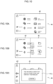
Fig. 10 is a diagram for explaining switching from the setting screen display state to the home screen display state. -
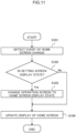
Fig. 11 is a flowchart for explaining the operation of the image forming apparatus according to the first embodiment of the disclosure. -
Fig. 12 is a flowchart for explaining the operation of the image forming apparatus according to the second embodiment of the disclosure. - Hereinafter, exemplary embodiments for carrying out the technology of the disclosure will be described in detail with reference to the drawings.
-
Fig. 1 is a diagram illustrating a system configuration of an image forming system according to a first embodiment; As illustrated inFig. 1 , the image forming system of the present embodiment includes animage forming apparatus 10 and aterminal device 20 connected to each other by anetwork 30. Theterminal device 20 generates print data and transmits the generated print data to theimage forming apparatus 10 via thenetwork 30. Theimage forming apparatus 10 receives print data transmitted from theterminal device 20 and outputs an image corresponding to the print data on a sheet. Theimage forming apparatus 10 is a so-called multi-function machine having a plurality of functions such as a printing function, a scanning function, a copying function, and a facsimile function. Theimage forming apparatus 10 is an example of an information processing device in the technology of the disclosure. - Next, a hardware configuration of the
image forming apparatus 10 in the image forming system of the present embodiment is illustrated inFig. 2 . - As illustrated in
Fig. 2 , theimage forming apparatus 10 includes a central processing unit (CPU) 11, amemory 12, astorage device 13 such as a hard disk drive, a communication interface (abbreviated as IF) 14 that transmits and receives data to and from an external device or the like via thenetwork 30, a user interface (abbreviated as UI)device 15 including a touch panel or a liquid crystal display and a keyboard, ascanner 16, and aprint engine 17. These components are connected to each other via acontrol bus 18. - The
print engine 17 prints an image on a recording medium such as printing paper through processes such as charging, exposure, development, transfer, and fixing. - The
CPU 11 is a processor that executes predetermined processing based on a control program stored in thememory 12 or thestorage device 13 to control the operation of theimage forming apparatus 10. In the present embodiment, theCPU 11 is described as reading and executing a control program stored in thememory 12 or thestorage device 13, but the program may be stored in a storage medium such as a compact disc read only memory (CD-ROM) and provided to theCPU 11. -
Fig. 3 is a block diagram illustrating a functional configuration of theimage forming apparatus 10 realized by executing the control program. - As illustrated in
Fig. 3 , theimage forming apparatus 10 of the present embodiment includes an eventinformation acquisition unit 31, acontrol unit 32, a display unit 33, anoperation input unit 34, a data transmission/reception unit 35, animage reading unit 36, and animage output unit 37. - The display unit 33 is controlled by the
control unit 32 and displays various types of information to the user. Theoperation input unit 34 inputs various operation information performed by the user. The data transmission/reception unit 35 transmits and receives data to and from an external device such as theterminal device 20. Theimage reading unit 36 reads a document image from a set document under the control of thecontrol unit 32. Theimage output unit 37 outputs an image on a recording medium such as printing paper under the control of thecontrol unit 32. - The
control unit 32 controls the overall operation of theimage forming apparatus 10, generates print data based on a print job received from theterminal device 20 via the data transmission/reception unit 35, and performs control to output the generated print data from theimage output unit 37 and control to read a document image by theimage reading unit 36, and the like. - The event
information acquisition unit 31 acquires event information that has occurred in theimage forming apparatus 10. Here, the event information is information on some event related to theimage forming apparatus 10, and includes, for example, information on a plurality of systems such as information on an abnormality relationship, information on an external operation relationship, and information on a login relationship. - Examples of the information on the abnormality relationship include information indicating a failure of the
image forming apparatus 10, information indicating that a door of a housing of theimage forming apparatus 10 is opened, and information indicating that an executing job has failed. - Examples of the information on the external operation relationship include information indicating that the setting of the
image forming apparatus 10 has been changed from theterminal device 20, information indicating that software is being installed in theimage forming apparatus 10, and the like. - Examples of the information on the login relationship include information indicating that a card for performing user authentication has been detected in a card reader provided in the
image forming apparatus 10, information indicating that money has been deposited or returned in a billing apparatus provided in theimage forming apparatus 10, and the like. - The
control unit 32 displays a home screen and a setting screen different from the home screen as operation screens on an operation panel provided in theimage forming apparatus 10. -
Fig. 4 is a display example of a home screen display state which is an example of theoperation screen 40 displayed on the operation panel.Fig. 5 is a diagram illustrating a hierarchical structure of theoperation screen 40 in the home screen display state. - As illustrated in
Figs. 4 and5 as an example, theoperation screen 40 has a two-layer structure of ahome screen 41 and asetting screen 42, and thesetting screen 42 is displayed in a superimposed manner on thehome screen 41. - The
home screen 41 is provided with icons for inputting instructions for various jobs such as copy and transmission of a scanned copy. - In the home screen display state, the
setting screen 42 is displayed in a reduced state that is displayed only in a partial region at the left end of theoperation screen 40. Thesetting screen 42 in the reduced state is provided with an icon and the like commonly used in the home screen display state and the setting screen display state, in addition to anenlargement icon 42a for enlarging thesetting screen 42. - In the home screen display state of the
operation screen 40, the entire area of thehome screen 41 is displayed, and thesetting screen 42 in the reduced state is displayed on the left side of thehome screen 41. - When the
operation screen 40 is in the home screen display state, thecontrol unit 32 accepts the operation of the user to display thesetting screen 42 in a superimposed manner on at least a part of thehome screen 41 displayed on theoperation screen 40, thereby bringing theoperation screen 40 into the setting screen display state. - As a way of changing the
operation screen 40 to the setting screen display state, thesetting screen 42 may be displayed in a superimposed manner so as to cover thehome screen 41 with thesetting screen 42 by gradually enlarging the display area of the setting screen by accepting the operation of the user, and theoperation screen 40 may be set to the setting screen display state. - Here, the operation of the user for bringing the
operation screen 40 into the setting screen display state may be, for example, a swipe operation of the user.Fig. 6 is a diagram for explaining switching from the home screen display state to the setting screen display state by the swipe operation. - When the
operation screen 40 is in the home screen display state, as illustrated inFig. 6A , the user touches theenlargement icon 42a on thesetting screen 42, and performs a swipe operation toward the right side in a state of touching theenlargement icon 42a. - By performing such a swipe operation, as illustrated in
Fig. 6B , thehome screen 41 is gradually covered with thesetting screen 42, and the display area of thesetting screen 42 is gradually enlarged. - Finally, as illustrated in
Fig. 6C , the state becomes the setting screen display state in which thesetting screen 42 is displayed on theentire operation screen 40. -
Fig. 7 is a display example of a setting screen display state which is an example of theoperation screen 40 displayed on the operation panel.Fig. 8 is a diagram illustrating the hierarchical structure of theoperation screen 40 in the setting screen display state. - As illustrated in
Figs. 7 and8 , in the setting screen display state of theoperation screen 40, since the entire area of thesetting screen 42 is displayed in the entire area of theoperation screen 40, thehome screen 41 is shielded by thesetting screen 42 and cannot be visually recognized by the user. - In the setting screen display state, the
setting screen 42 is displayed in an enlarged state displayed in the entire area of theoperation screen 40. Thesetting screen 42 in the enlarged state is provided with, in addition to areduction icon 42b for reducing thesetting screen 42, icons to be commonly used in the home screen display state and the setting screen display state, icons for performing various settings such as language switching and customization, and the like. -
Fig. 9 is a display example of the event information displayed on thehome screen 41. When the eventinformation acquisition unit 31 acquires the event information, thecontrol unit 32 displays anevent display window 41a at the center of thehome screen 41 and updates the display of thehome screen 41. - However, when the
operation screen 40 is in the setting screen display state, even when the display of thehome screen 41 is updated, it cannot be visually recognized by the user. Therefore, when theoperation screen 40 is in the setting screen display state and an event that changes the display content of thehome screen 41 occurs, thecontrol unit 32 changes the display mode of thesetting screen 42 so that the change in the display content that has occurred on thehome screen 41 becomes visible, thereby changing theoperation screen 40 from the setting screen display state to the home screen display state, and displaying theevent display window 41a on thehome screen 41. - For example, in a case in which the event
information acquisition unit 31 acquires information indicating a failure of theimage forming apparatus 10 as the event information, thecontrol unit 32 displays theevent display window 41a indicating a failure of theimage forming apparatus 10 at the center of thehome screen 41 and updates the display of thehome screen 41 as illustrated inFig. 9 . - As a way of changing the display mode of the
setting screen 42 so that the user can visually recognize theevent display window 41a displayed on thehome screen 41, for example, thesetting screen 42 may be brought into a reduced state and theoperation screen 40 may be brought into a home screen display state.Fig. 10 is a diagram for explaining switching from the setting screen display state to the home screen display state. - When detecting that an event that the display of the
home screen 41 changes occurs in a state where theoperation screen 40 is in the setting screen display state as illustrated inFig. 10A , thecontrol unit 32 gradually reduces the display area of thesetting screen 42 as illustrated inFig. 10B . - Then, finally, as illustrated in
Fig. 10C , thecontrol unit 32 brings theoperation screen 40 into the home screen display state, displays the entire area of thehome screen 41 on theoperation screen 40, and allows the user to visually recognize theevent display window 41a. - Next, the operation of the
image forming apparatus 10 in the present embodiment will be described with reference to a flowchart ofFig. 11 . - First, in Step S101, the
control unit 32 detects occurrence of an event in which the display of thehome screen 41 changes. - Then, in Step S102, the
control unit 32 determines whether or not theoperation screen 40 is in the setting screen display state. - In a case in which it is determined in Step S102 that the operation screen is not in the setting screen display state, that is, the determination in Step S102 is No, the
control unit 32 updates the display of thehome screen 41 so as to display theevent display window 41a in Step S104. - In a case in which it is determined in Step S102 that the operation screen is in the setting screen display state, that is, the determination in Step S102 is Yes, the
control unit 32 changes theoperation screen 40 from the setting screen display state to the home screen display state in Step S103, and then updates the display of the home screen so as to display theevent display window 41a in Step S104. - In the first embodiment, in the case of an event in which the display of the
home screen 41 changes in the setting screen display state, the state is always changed to the home screen display state, and theevent display window 41a is displayed. - In the present embodiment, a mode will be described in which the setting screen display state is maintained in a case where an operation input on the
setting screen 42 is possible even in a case in which an event occurs in which the display of thehome screen 41 changes in the setting screen display state. - Note that a hardware configuration (see
Figs. 1 to 3 ) of theimage forming apparatus 10 according to the present embodiment is similar to that of the first embodiment, and thus description thereof is omitted. The operation screen 40 (seeFigs. 4 and8 ) according to the present embodiment is also similar to that of the first embodiment, and thus description thereof is omitted. - In the setting screen display state, when a failure occurs in the
image forming apparatus 10, the setting of theimage forming apparatus 10 is changed from theterminal device 20, or software is installed in theimage forming apparatus 10, operation input on thesetting screen 42 is hindered. - Therefore, when the event
information acquisition unit 31 acquires, as the event information, information indicating failure of theimage forming apparatus 10, information indicating that the setting of theimage forming apparatus 10 has been changed from theterminal device 20, information indicating that the software is being installed on theimage forming apparatus 10, or the like, that is, when the operation input on thesetting screen 42 is no longer accepted, thecontrol unit 32 changes the display mode of thesetting screen 42 so that the change in the display content occurring on thehome screen 41 can be visually recognized, thereby changing theoperation screen 40 from the setting screen display state to the home screen display state, and displays theevent display window 41a on thehome screen 41. - Meanwhile, even in a case in which an event occurs in which the display of the home screen changes, in a case where an operation input on the setting screen is possible, there is no problem even in a state where the setting screen display state is maintained without changing the
operation screen 40 to the home screen display state. - Therefore, in a case in which the event
information acquisition unit 31 acquires information other than the above as the event information, that is, when the operation input on thesetting screen 42 can be received, thecontrol unit 32 maintains the setting screen display state without changing the display mode of thesetting screen 42. - The operation of the
image forming apparatus 10 in the present embodiment will be described with reference to a flowchart ofFig. 12 . - First, in Step S111, the
control unit 32 detects occurrence of an event in which the display of thehome screen 41 changes. - Then, in Step S112, the
control unit 32 determines whether or not theoperation screen 40 is in the setting screen display state. - In a case in which it is determined in Step S112 that the operation screen is not in the setting screen display state, that is, the determination in Step S112 is No, the
control unit 32 updates the display of the home screen so as to display theevent display window 41a in Step S115. - In a case in which it is determined in Step S112 that the operation screen is in the setting screen display state, that is, the determination in Step S112 is Yes, the
control unit 32 determines in Step S113 whether or not an operation input on thesetting screen 42 is possible. - In a case in which it is determined in Step S113 that the operation input on the
setting screen 42 is possible, that is, the determination in Step S113 is Yes, thecontrol unit 32 updates the display of thehome screen 41 so as to display theevent display window 41a while maintaining the setting screen display state in Step S115. - In a case in which it is determined in Step S113 that the operation input on the
setting screen 42 is impossible, that is, the determination in Step S113 is No, thecontrol unit 32 changes theoperation screen 40 from the setting screen display state to the home screen display state in Step S114, and then updates the display of the home screen so as to display theevent display window 41a inStep S 115. - In each of the above embodiments, a processor refers to a processor in a broad sense, and includes a general-purpose processor (for example, CPU: Central Processing Unit, etc.) or a dedicated processor (for example, GPU: Graphics Processing Unit, ASIC: Application Specific Integrated Circuit, FPGA: Field Programmable Gate Array, Programmable Logic Device, and the like).
- In addition, the operation of the processor in each of the embodiments may be performed not only by one processor but also by a plurality of processors existing at physically separated positions in cooperation. In addition, the order of each operation of the processor is not limited to the order described in each of the embodiments and may be changed, as appropriate.
- Furthermore, in the above-described embodiment, a case where the technology of the disclosure is applied to the image forming apparatus that forms the image on the recording medium has been described. However, the technology of the disclosure is not limited thereto, and the technology of the disclosure can be similarly applied to an information processing device such as a personal computer or a mobile terminal device that stores processing execution information for executing preset processing and executes processing using the stored processing execution information.
- The disclosure of
Japanese Patent Application No. 2021-024680 filed on February 18, 2021
Claims (7)
- An information processing device comprising:
a processor configured to:cause display of a second screen, which is different from a first screen displayed on an operation screen, superimposed on at least a part of the first screen as a result of accepting an operation of a user, andchange a display mode of the second screen such that a change in display content occurring on the first screen becomes visible in a case in which display content of the first screen changes. - The information processing device according to claim 1, wherein the processor is configured to cause display of the second screen so as to cover the first screen with the second screen by gradually enlarging a display area of the second screen, as a result of accepting the operation of the user.
- The information processing device according to claim 2, wherein the processor is configured to cause display of the second screen so as to cover the first screen with the second screen by gradually enlarging the display area of the second screen, as a result of accepting a swipe operation of the user.
- The information processing device according to any one of claims 1 to 3,
wherein the processor is configured to change the display mode of the second screen by gradually reducing the display area of the second screen in a case in which the display content of the first screen changes. - The information processing device according to any one of claims 1 to 4,
wherein the processor is configured to change the display mode of the second screen such that a change in display content occurring on the first screen becomes visible in a case in which an operation input on the second screen is no longer accepted due to occurrence of the event. - The information processing device according to claim 5, wherein the processor is configured not to change a display mode of the second screen in a case in which an operation input on the second screen can be received even when the event occurs.
- A program executable by a computer to perform processing comprising:causing display of a second screen, which is different from a first screen displayed on an operation screen, superimposed on at least a part of the first screen as a result of accepting an operation of a user, andchanging a display mode of the second screen such that a change in display content occurring on the first screen becomes visible in a case in which display content of the first screen changes.
Applications Claiming Priority (2)
| Application Number | Priority Date | Filing Date | Title |
|---|---|---|---|
| JP2021024680A JP2022126543A (en) | 2021-02-18 | 2021-02-18 | Information processing device and program |
| PCT/JP2022/005437 WO2022176779A1 (en) | 2021-02-18 | 2022-02-10 | Information processing device and program |
Publications (2)
| Publication Number | Publication Date |
|---|---|
| EP4296785A1 true EP4296785A1 (en) | 2023-12-27 |
| EP4296785A4 EP4296785A4 (en) | 2024-07-31 |
Family
ID=82931670
Family Applications (1)
| Application Number | Title | Priority Date | Filing Date |
|---|---|---|---|
| EP22756099.2A Pending EP4296785A4 (en) | 2021-02-18 | 2022-02-10 | Information processing device and program |
Country Status (5)
| Country | Link |
|---|---|
| US (1) | US20240231585A9 (en) |
| EP (1) | EP4296785A4 (en) |
| JP (1) | JP2022126543A (en) |
| CN (1) | CN116868159A (en) |
| WO (1) | WO2022176779A1 (en) |
Family Cites Families (26)
| Publication number | Priority date | Publication date | Assignee | Title |
|---|---|---|---|---|
| JPH1124739A (en) * | 1997-07-08 | 1999-01-29 | Canon Inc | Event notification device, event notification method, and storage medium |
| US6184883B1 (en) * | 1998-03-18 | 2001-02-06 | International Business Machines Corporation | Computer system, program product and method utilizing in-focus switch delay for user interface components |
| US6654037B1 (en) * | 1999-11-10 | 2003-11-25 | Sharp Laboratories Of America, Inc. | Embedded windows in background image |
| US7380218B2 (en) * | 2003-03-27 | 2008-05-27 | International Business Machines Corporation | Method and apparatus for managing windows |
| US7865839B2 (en) * | 2004-03-05 | 2011-01-04 | Aol Inc. | Focus stealing prevention |
| US7490299B2 (en) * | 2004-06-30 | 2009-02-10 | International Business Machines Corporation | System and method for handling unexpected focus change messages in a computing device |
| US20060059432A1 (en) * | 2004-09-15 | 2006-03-16 | Matthew Bells | User interface having viewing area with non-transparent and semi-transparent regions |
| JP2006107301A (en) | 2004-10-08 | 2006-04-20 | Canon Inc | Extended control unit |
| US20060190831A1 (en) * | 2005-02-22 | 2006-08-24 | Kelso Scott E | System and method for delaying pop-up window |
| CN101238437B (en) * | 2005-08-11 | 2013-03-06 | 皇家飞利浦电子股份有限公司 | Method of driving an interactive system and user interface system |
| US9021375B2 (en) * | 2006-08-15 | 2015-04-28 | International Business Machines Corporation | Notification of state transition of an out-of-focus application |
| JP5523011B2 (en) * | 2009-08-13 | 2014-06-18 | キヤノン株式会社 | Information processing apparatus, information processing method, and program |
| EP3907593B1 (en) * | 2010-01-19 | 2025-03-26 | LG Electronics, Inc. | Mobile terminal and control method thereof |
| JP5509938B2 (en) | 2010-03-05 | 2014-06-04 | 株式会社リコー | Image forming apparatus and information display method |
| US8560960B2 (en) * | 2010-11-23 | 2013-10-15 | Apple Inc. | Browsing and interacting with open windows |
| BR112014002039B1 (en) * | 2011-08-05 | 2022-02-01 | Interdigital Ce Patent Holdings | User interface for a video player, and method for controlling a video player that has a touch-activated screen |
| US9377937B2 (en) * | 2012-04-06 | 2016-06-28 | Samsung Electronics Co., Ltd. | Method and device for executing object on display |
| JP5806973B2 (en) * | 2012-05-08 | 2015-11-10 | ソフトバンク株式会社 | Information terminal equipment |
| JP5576572B1 (en) * | 2013-03-07 | 2014-08-20 | 三菱電機株式会社 | Engineering tools |
| JP6234233B2 (en) | 2014-01-10 | 2017-11-22 | キヤノン株式会社 | Information processing apparatus, information processing method, and program |
| EP3270372B1 (en) * | 2015-03-13 | 2023-10-18 | Panasonic Intellectual Property Management Co., Ltd. | Electronic device and method for controlling same |
| KR102426070B1 (en) * | 2015-11-18 | 2022-07-28 | 삼성전자 주식회사 | Electronic apparatus and method for configuring of display thereof |
| US20190095047A1 (en) * | 2017-09-25 | 2019-03-28 | International Business Machines Corporation | Safely capturing input when a dialog is presented |
| JP7173814B2 (en) * | 2018-09-28 | 2022-11-16 | キヤノン株式会社 | Information processing device, control method and program |
| JP2021024680A (en) | 2019-08-02 | 2021-02-22 | キヤノンファインテックニスカ株式会社 | Sheet processing device and control method thereof |
| US12406041B2 (en) * | 2020-09-07 | 2025-09-02 | Qualcomm Incorporated | System and method for capturing notes on a mobile device |
-
2021
- 2021-02-18 JP JP2021024680A patent/JP2022126543A/en active Pending
-
2022
- 2022-02-10 EP EP22756099.2A patent/EP4296785A4/en active Pending
- 2022-02-10 US US18/546,596 patent/US20240231585A9/en active Pending
- 2022-02-10 CN CN202280015372.4A patent/CN116868159A/en active Pending
- 2022-02-10 WO PCT/JP2022/005437 patent/WO2022176779A1/en not_active Ceased
Also Published As
| Publication number | Publication date |
|---|---|
| WO2022176779A1 (en) | 2022-08-25 |
| JP2022126543A (en) | 2022-08-30 |
| US20240231585A9 (en) | 2024-07-11 |
| US20240134510A1 (en) | 2024-04-25 |
| CN116868159A (en) | 2023-10-10 |
| EP4296785A4 (en) | 2024-07-31 |
Similar Documents
| Publication | Publication Date | Title |
|---|---|---|
| US10180771B2 (en) | User interface provided with display unit for displaying screen | |
| US20190089850A1 (en) | Information processing apparatus and non-transitory computer readable medium | |
| JP5887847B2 (en) | Operation display apparatus, image forming apparatus, control method, and control program | |
| US20130127688A1 (en) | Display system provided with first display device and second display device | |
| CN110851037A (en) | Information processing apparatus and recording medium | |
| US8982397B2 (en) | Image processing device, non-transitory computer readable recording medium and operational event determining method | |
| US10582072B2 (en) | Information processing apparatus and non-transitory computer readable medium comprising a display screen including basic operator for execution of certain function | |
| US11055031B2 (en) | Information processing apparatus and non-transitory computer readable medium | |
| EP4296785A1 (en) | Information processing device and program | |
| CN107786768B (en) | Information processing apparatus, image forming apparatus, and information processing method | |
| US20190141206A1 (en) | Image processing system, information processing device, image processing device and non-transitory recording medium | |
| CN114615386B (en) | Information processing device, image processing device, method for controlling information processing device, and recording medium | |
| US20240134588A1 (en) | Information processing device and program | |
| JP2012014287A (en) | Information processing device, electrical equipment and server | |
| JP7505307B2 (en) | Information processing device and program | |
| US11445074B2 (en) | Information processing device, touch panel display method, and recording medium | |
| US20250211690A1 (en) | Information processing system and non-transitory computer-readable recording medium | |
| US20240330007A1 (en) | Control method for information processing apparatus and non-volatile storage medium | |
| JP2013118018A (en) | Information processing device, electronic device, and server | |
| US11588946B2 (en) | Display apparatus that displays scroll bar in displayed portion of operation screen reduced by superimposed keyboard, and image forming apparatus | |
| US20250106330A1 (en) | Information processing apparatus, control method, and storage medium | |
| US20230141058A1 (en) | Display apparatus and method for controlling display apparatus | |
| US20260086752A1 (en) | Information processing apparatus, control method of information processing apparatus, and storage medium | |
| JP7625435B2 (en) | Information processing device and program | |
| JP5509938B2 (en) | Image forming apparatus and information display method |
Legal Events
| Date | Code | Title | Description |
|---|---|---|---|
| STAA | Information on the status of an ep patent application or granted ep patent |
Free format text: STATUS: THE INTERNATIONAL PUBLICATION HAS BEEN MADE |
|
| PUAI | Public reference made under article 153(3) epc to a published international application that has entered the european phase |
Free format text: ORIGINAL CODE: 0009012 |
|
| STAA | Information on the status of an ep patent application or granted ep patent |
Free format text: STATUS: REQUEST FOR EXAMINATION WAS MADE |
|
| 17P | Request for examination filed |
Effective date: 20230817 |
|
| AK | Designated contracting states |
Kind code of ref document: A1 Designated state(s): AL AT BE BG CH CY CZ DE DK EE ES FI FR GB GR HR HU IE IS IT LI LT LU LV MC MK MT NL NO PL PT RO RS SE SI SK SM TR |
|
| DAV | Request for validation of the european patent (deleted) | ||
| DAX | Request for extension of the european patent (deleted) | ||
| REG | Reference to a national code |
Ref country code: DE Ref legal event code: R079 Free format text: PREVIOUS MAIN CLASS: G03G0021000000 Ipc: G03G0015000000 |
|
| A4 | Supplementary search report drawn up and despatched |
Effective date: 20240627 |
|
| RIC1 | Information provided on ipc code assigned before grant |
Ipc: G06F 3/0483 20130101ALI20240621BHEP Ipc: G06F 3/0488 20220101ALI20240621BHEP Ipc: G06F 3/0481 20220101ALI20240621BHEP Ipc: B41J 29/42 20060101ALI20240621BHEP Ipc: H04N 1/00 20060101ALI20240621BHEP Ipc: G03G 15/00 20060101AFI20240621BHEP |
|
| STAA | Information on the status of an ep patent application or granted ep patent |
Free format text: STATUS: EXAMINATION IS IN PROGRESS |
|
| 17Q | First examination report despatched |
Effective date: 20260102 |