EP4296758A1 - Head wearable display device with image monitoring - Google Patents
Head wearable display device with image monitoring Download PDFInfo
- Publication number
- EP4296758A1 EP4296758A1 EP23179899.2A EP23179899A EP4296758A1 EP 4296758 A1 EP4296758 A1 EP 4296758A1 EP 23179899 A EP23179899 A EP 23179899A EP 4296758 A1 EP4296758 A1 EP 4296758A1
- Authority
- EP
- European Patent Office
- Prior art keywords
- image
- waveguide
- processor
- monitor sensor
- monitored
- Prior art date
- Legal status (The legal status is an assumption and is not a legal conclusion. Google has not performed a legal analysis and makes no representation as to the accuracy of the status listed.)
- Pending
Links
Images


Classifications
-
- G—PHYSICS
- G02—OPTICS
- G02B—OPTICAL ELEMENTS, SYSTEMS OR APPARATUS
- G02B27/00—Optical systems or apparatus not provided for by any of the groups G02B1/00 - G02B26/00, G02B30/00
- G02B27/01—Head-up displays
- G02B27/0101—Head-up displays characterised by optical features
-
- G—PHYSICS
- G02—OPTICS
- G02B—OPTICAL ELEMENTS, SYSTEMS OR APPARATUS
- G02B27/00—Optical systems or apparatus not provided for by any of the groups G02B1/00 - G02B26/00, G02B30/00
- G02B27/01—Head-up displays
- G02B27/017—Head mounted
- G02B27/0172—Head mounted characterised by optical features
-
- G—PHYSICS
- G02—OPTICS
- G02B—OPTICAL ELEMENTS, SYSTEMS OR APPARATUS
- G02B6/00—Light guides; Structural details of arrangements comprising light guides and other optical elements, e.g. couplings
- G02B6/10—Light guides; Structural details of arrangements comprising light guides and other optical elements, e.g. couplings of the optical waveguide type
-
- G—PHYSICS
- G06—COMPUTING OR CALCULATING; COUNTING
- G06F—ELECTRIC DIGITAL DATA PROCESSING
- G06F3/00—Input arrangements for transferring data to be processed into a form capable of being handled by the computer; Output arrangements for transferring data from processing unit to output unit, e.g. interface arrangements
- G06F3/14—Digital output to display device ; Cooperation and interconnection of the display device with other functional units
- G06F3/147—Digital output to display device ; Cooperation and interconnection of the display device with other functional units using display panels
-
- G—PHYSICS
- G09—EDUCATION; CRYPTOGRAPHY; DISPLAY; ADVERTISING; SEALS
- G09G—ARRANGEMENTS OR CIRCUITS FOR CONTROL OF INDICATING DEVICES USING STATIC MEANS TO PRESENT VARIABLE INFORMATION
- G09G3/00—Control arrangements or circuits, of interest only in connection with visual indicators other than cathode-ray tubes
- G09G3/001—Control arrangements or circuits, of interest only in connection with visual indicators other than cathode-ray tubes using specific devices not provided for in groups G09G3/02 - G09G3/36, e.g. using an intermediate record carrier such as a film slide; Projection systems; Display of non-alphanumerical information, solely or in combination with alphanumerical information, e.g. digital display on projected diapositive as background
- G09G3/002—Control arrangements or circuits, of interest only in connection with visual indicators other than cathode-ray tubes using specific devices not provided for in groups G09G3/02 - G09G3/36, e.g. using an intermediate record carrier such as a film slide; Projection systems; Display of non-alphanumerical information, solely or in combination with alphanumerical information, e.g. digital display on projected diapositive as background to project the image of a two-dimensional display, such as an array of light emitting or modulating elements or a CRT
-
- G—PHYSICS
- G02—OPTICS
- G02B—OPTICAL ELEMENTS, SYSTEMS OR APPARATUS
- G02B27/00—Optical systems or apparatus not provided for by any of the groups G02B1/00 - G02B26/00, G02B30/00
- G02B27/01—Head-up displays
- G02B27/0101—Head-up displays characterised by optical features
- G02B2027/0112—Head-up displays characterised by optical features comprising device for genereting colour display
- G02B2027/0116—Head-up displays characterised by optical features comprising device for genereting colour display comprising devices for correcting chromatic aberration
-
- G—PHYSICS
- G02—OPTICS
- G02B—OPTICAL ELEMENTS, SYSTEMS OR APPARATUS
- G02B27/00—Optical systems or apparatus not provided for by any of the groups G02B1/00 - G02B26/00, G02B30/00
- G02B27/01—Head-up displays
- G02B27/0101—Head-up displays characterised by optical features
- G02B2027/0118—Head-up displays characterised by optical features comprising devices for improving the contrast of the display / brillance control visibility
-
- G—PHYSICS
- G02—OPTICS
- G02B—OPTICAL ELEMENTS, SYSTEMS OR APPARATUS
- G02B27/00—Optical systems or apparatus not provided for by any of the groups G02B1/00 - G02B26/00, G02B30/00
- G02B27/01—Head-up displays
- G02B27/0101—Head-up displays characterised by optical features
- G02B2027/0138—Head-up displays characterised by optical features comprising image capture systems, e.g. camera
-
- G—PHYSICS
- G02—OPTICS
- G02B—OPTICAL ELEMENTS, SYSTEMS OR APPARATUS
- G02B27/00—Optical systems or apparatus not provided for by any of the groups G02B1/00 - G02B26/00, G02B30/00
- G02B27/01—Head-up displays
- G02B27/0101—Head-up displays characterised by optical features
- G02B2027/014—Head-up displays characterised by optical features comprising information/image processing systems
-
- G—PHYSICS
- G02—OPTICS
- G02B—OPTICAL ELEMENTS, SYSTEMS OR APPARATUS
- G02B27/00—Optical systems or apparatus not provided for by any of the groups G02B1/00 - G02B26/00, G02B30/00
- G02B27/01—Head-up displays
- G02B27/017—Head mounted
- G02B2027/0178—Eyeglass type
-
- G—PHYSICS
- G09—EDUCATION; CRYPTOGRAPHY; DISPLAY; ADVERTISING; SEALS
- G09G—ARRANGEMENTS OR CIRCUITS FOR CONTROL OF INDICATING DEVICES USING STATIC MEANS TO PRESENT VARIABLE INFORMATION
- G09G2330/00—Aspects of power supply; Aspects of display protection and defect management
- G09G2330/12—Test circuits or failure detection circuits included in a display system, as permanent part thereof
-
- G—PHYSICS
- G09—EDUCATION; CRYPTOGRAPHY; DISPLAY; ADVERTISING; SEALS
- G09G—ARRANGEMENTS OR CIRCUITS FOR CONTROL OF INDICATING DEVICES USING STATIC MEANS TO PRESENT VARIABLE INFORMATION
- G09G2360/00—Aspects of the architecture of display systems
- G09G2360/14—Detecting light within display terminals, e.g. using a single or a plurality of photosensors
- G09G2360/145—Detecting light within display terminals, e.g. using a single or a plurality of photosensors the light originating from the display screen
-
- G—PHYSICS
- G09—EDUCATION; CRYPTOGRAPHY; DISPLAY; ADVERTISING; SEALS
- G09G—ARRANGEMENTS OR CIRCUITS FOR CONTROL OF INDICATING DEVICES USING STATIC MEANS TO PRESENT VARIABLE INFORMATION
- G09G2380/00—Specific applications
- G09G2380/12—Avionics applications
-
- G—PHYSICS
- G09—EDUCATION; CRYPTOGRAPHY; DISPLAY; ADVERTISING; SEALS
- G09G—ARRANGEMENTS OR CIRCUITS FOR CONTROL OF INDICATING DEVICES USING STATIC MEANS TO PRESENT VARIABLE INFORMATION
- G09G3/00—Control arrangements or circuits, of interest only in connection with visual indicators other than cathode-ray tubes
- G09G3/001—Control arrangements or circuits, of interest only in connection with visual indicators other than cathode-ray tubes using specific devices not provided for in groups G09G3/02 - G09G3/36, e.g. using an intermediate record carrier such as a film slide; Projection systems; Display of non-alphanumerical information, solely or in combination with alphanumerical information, e.g. digital display on projected diapositive as background
- G09G3/003—Control arrangements or circuits, of interest only in connection with visual indicators other than cathode-ray tubes using specific devices not provided for in groups G09G3/02 - G09G3/36, e.g. using an intermediate record carrier such as a film slide; Projection systems; Display of non-alphanumerical information, solely or in combination with alphanumerical information, e.g. digital display on projected diapositive as background to produce spatial visual effects
Definitions
- Head wearable display (HWD) devices such as and helmet mounted display (HMD) devices
- HWD helmet mounted display
- the implementation challenges for monitoring schemes are significant due to the small size and tight integration of head worn components.
- future HWDs with COTS components include flight guidance symbology such as the AIII mode used for Category III landing credit and/or vision systems enabling low visibility operations, or if such HWDs are used in single pilot operations (SPO), some form of display path monitoring would likely be required.
- SPO single pilot operations
- inventions of the inventive concepts disclosed herein are directed to a system.
- the system may include a head wearable display device and at least one processor.
- the head wearable display device may include a waveguide display and at least one image monitor sensor.
- the waveguide display may be implemented at least one of in or on the head wearable display device.
- the waveguide display may include a waveguide and an optical system, the optical system configured to: receive image data corresponding to an image; and project the image at least through the waveguide to be displayed to a user.
- Each of the at least one image monitor sensor may be implemented in or on the head wearable display device.
- Each of the at least one image monitor sensor may be optically coupled to the waveguide or the optical system of the waveguide display.
- Each of the at least one image monitor sensor may be configured to: capture at least a portion of the image as a monitored image; and output monitored image data corresponding to the monitored image.
- Each of the at least one processor may be implemented in the head wearable display device or in a computing device separate from the head wearable display device. The at least one processor may be configured to: receive the monitored image data from each of the at least one image monitor sensor; and based at least on the monitored image data, determine whether the waveguide display displayed the image correctly.
- inventions of the inventive concepts disclosed herein are directed to a method.
- the method may include: providing a waveguide display of a head wearable display device, the waveguide display implemented at least one of in or on the head wearable display device, the waveguide display comprising a waveguide and an optical system; receiving, by the optical system, image data corresponding to an image; projecting, by the optical system, the image at least through the waveguide to be displayed to a user; providing at least one image monitor sensor of the head wearable display device, each of the at least one image monitor sensor implemented in or on the head wearable display device, each of the at least one image monitor sensor optically coupled to the waveguide or the optical system of the waveguide display; capturing, by each of the at least one image monitor sensor, at least a portion of the image as a monitored image; outputting, by each of the at least one image monitor sensor, monitored image data corresponding to the monitored image; providing at least one processor, each of the at least one processor implemented in the head wearable display device or in a computing device
- inventive concepts are not limited in their application to the details of construction and the arrangement of the components or steps or methodologies set forth in the following description or illustrated in the drawings.
- inventive concepts disclosed herein may be practiced without these specific details.
- well-known features may not be described in detail to avoid unnecessarily complicating the instant disclosure.
- inventive concepts disclosed herein are capable of other embodiments or of being practiced or carried out in various ways. Also, it is to be understood that the phraseology and terminology employed herein is for the purpose of description and should not be regarded as limiting.
- a letter following a reference numeral is intended to reference an embodiment of the feature or element that may be similar, but not necessarily identical, to a previously described element or feature bearing the same reference numeral (e.g., 1, 1a, 1b).
- reference numeral e.g. 1, 1a, 1b
- Such shorthand notations are used for purposes of convenience only, and should not be construed to limit the inventive concepts disclosed herein in any way unless expressly stated to the contrary.
- any reference to "one embodiment,” or “some embodiments” means that a particular element, feature, structure, or characteristic described in connection with the embodiment is included in at least one embodiment of the inventive concepts disclosed herein.
- the appearances of the phrase “in some embodiments” in various places in the specification are not necessarily all referring to the same embodiment, and embodiments of the inventive concepts disclosed may include one or more of the features expressly described or inherently present herein, or any combination of sub-combination of two or more such features, along with any other features which may not necessarily be expressly described or inherently present in the instant disclosure.
- embodiments of the inventive concepts disclosed herein are directed to a method and a system including a head wearable device having a waveguide display and an image monitor sensor (e.g., a camera or a photodiode).
- a head wearable device having a waveguide display and an image monitor sensor (e.g., a camera or a photodiode).
- an image monitor sensor e.g., a camera or a photodiode
- a monitoring concept of some embodiments relies on a feature in many waveguide optical systems which presents a "pre-expanded" and collimated image at a location that can be captured by a small image monitor sensor, such as a small camera or photodiode(s).
- the system 100 may be implemented as any suitable system, such as at least one vehicle (e.g., an aircraft 102).
- the system 100 may include an aircraft 102.
- the HWD device 104 may include at least one head and/or pose tracking system 106, at least one processor 108, at least one memory device 109, at least one waveguide display 110, and/or at least one image monitor sensor 115 (e.g., a camera or a photodiode(s)), some or all of which may be optically and/or communicatively coupled at any given time.
- the waveguide display 110 may include at least one optical system 112, at least one waveguide 114, and/or the at least one image monitor sensor 115, some or all of which may be optically and/or communicatively coupled at any given time.
- the HWD device 104 may be in the aircraft cockpit 200.
- the head and/or pose tracking system 106 may have optical, magnetic, and/or inertial tracking capability.
- the head and/or pose tracking system 106 may include head and/or pose tracking capabilities and/or be coordinated with head and/or pose tracking capabilities of another head and/or pose tracking system (e.g., 124), for example, such that the head and/or pose tracking operations are relative to a position and/or orientation of a user and/or relative to a position and/or orientation to a vehicle (e.g., the aircraft 102).
- the head and/or pose tracking system 106 may be configured to track the Line of Sight (LOS) of the waveguide display 110 optical system.
- LOS Line of Sight
- the processor 108 may be configured to: based at least on the monitored image data, determine that the waveguide display 110 displayed the image incorrectly. For example, the processor 108 may be configured to: based at least on the monitored image data, determine that the waveguide display 110 displayed the image as a flipped image or a frozen image. For example, the processor 108 may be configured to: based at least on the monitored image data, determine that the waveguide display 110 displayed the image brighter than a predetermined maximum brightness threshold or less bright than a predetermined minimum brightness threshold. For example, the processor 108 may be configured to: based at least on the monitored image data, determine that the waveguide display 110 displayed the image with incorrectly positioned symbology, incorrect symbology, or missing symbology.
- the processor 108 may be configured to: based at least on the monitored image data, determine that the waveguide display 110 displayed image content of the image incorrectly. For example, the processor 108 may be configured to: based at least on the determination that the waveguide display 110 displayed the image incorrectly, disable the given waveguide display 110. For example, the processor 108 may be configured to: determine whether at least one of the monitored image of each of the a least one image monitor sensor 115 is aligned with a field of view of the user.
- the processor 108 may be configured to: compare the monitored image data against the second waveguide monitored image; and based at least on the comparison of the monitored image data against the second waveguide monitored image data, determine whether one of the waveguide display 110 or the second waveguide display 110 displayed the image incorrectly.
- the waveguide display 111 may include at least one lens, at least one mirror, diffraction gratings, at least one polarization sensitive component, at least one beam splitter, at least one waveguide 114, at least one light pipe, at least one window, and/or the projector 116.
- a given image monitor sensor 115 may be optically coupled to the waveguide 114 at a position on the waveguide 114 above a user-viewable portion of the waveguide 114, wherein the given image monitor sensor 115 is configured to capture at least the at least the portion of the image emitted from the position on the waveguide 114 above the user-viewable portion of the waveguide 114.
- the computing device 118 may be implemented as any suitable computing device, such as an avionics computing device.
- the computing device 118 may include at least one memory 120, at least one processor 122, and/or at least one head and/or pose tracking system 124, some or all of which may be communicatively coupled at any given time.
- the processor 122 may be configured to: receive the monitored image data from each of the at least one image monitor sensor 115; and/or based at least on the monitored image data, determine whether the waveguide display 110 displayed the image correctly.
- the processor 122 may be configured to: obtain the image data corresponding to the image; compare the monitored image of each of the at least one image monitor sensor 115 against the image; and/or based at least on the comparison of the monitored image of each of the at least one image monitor sensor against the image, determine whether the given waveguide display 110 displayed the image correctly.
- the processor 122 may be configured to: based at least on the monitored image data, determine that the waveguide display 110 displayed image content of the image incorrectly. For example, the processor 122 may be configured to: based at least on the determination that the waveguide display 110 displayed the image incorrectly, disable the given waveguide display 110. For example, the processor 122 may be configured to: determine whether at least one of the monitored image of each of the a least one image monitor sensor 115 is aligned with a field of view of the user.
- the processor 122 may be configured to: compare the monitored image data against the second waveguide monitored image; and based at least on the comparison of the monitored image data against the second waveguide monitored image data, determine whether one of the waveguide display 110 or the second waveguide display 110 displayed the image incorrectly.
- the head and/or pose tracking system 106 may include at least one sensor (not shown), at least one processor 302, at least one memory 306, and/or at least one storage device 308, as well as other components, equipment, and/or devices commonly included in a head and/or pose tracking system, some or all of which may be communicatively coupled at any time, as shown in FIG. 3 .
- the at least one processor 302 may be implemented as any suitable processor(s), such as at least one general purpose processor, at least one central processing unit (CPU), at least one image processor, at least one graphics processing unit (GPU), at least one field-programmable gate array (FPGA), and/or at least one special purpose processor configured to execute instructions for performing (e.g., collectively performing if more than one processor) any or all of the operations disclosed throughout.
- the at least one sensor may be at least one optical sensor (e.g., an optical infrared sensor (e.g., an infrared camera) configured to detect infrared light emitted and/or reflected from the fiducials 202), at least one magnetic sensor, and/or at least one inertial sensor.
- the head and/or pose tracking system 124 may be configured to determine and track a position and an orientation of a user's head relative to an environment (e.g., a cockpit 200).
- the head and/or pose tracking system 106 may be configured for performing fully automatic head and/or pose tracking operations in real time.
- the processor 302 of the head and/or pose tracking system 124 may be configured to process data received from the sensors 204 and output processed data (e.g., head and/or pose tracking data) to one of the computing devices of the system 100 and/or the processor 108 for use in generating images aligned with the user's field of view, such as augmented reality or virtual reality images aligned with the user's field of view to be displayed by the waveguide display 110.
- the processor 302 may be configured to determine and track a position and orientation of a user's head relative to an environment (e.g., a cockpit 200).
- the processor 302 may be configured to receive IMU data from the IMU 126 and/or IRS data from the IRS 128. Additionally, for example, the processor 302 may be configured to generate position and orientation data associated with such determined information and output the generated position and orientation data.
- the processor 302 may be configured to run various software applications or computer code stored in a non-transitory computer-readable medium (e.g., memory 304 and/or storage device 306) and configured to execute various instructions or operations.
- the at least one processor 302 may be implemented as a special purpose processor configured to execute instructions for performing (e.g., collectively performing if more than one processor) any or all of the operations disclosed throughout.
- At least one processor e.g., 108 and/or 122
- each of the at least one processor e.g., 108 and/or 122 implemented in the head wearable display device 104 or in a computing device 118 separate from the head wearable display device 104
- the at least one processor e.g., 108 and/or 122
- the at least one processor may be at least two processors including at least one head wearable display device processor 108 and at least one at least one computing device processor 122 collectively configured to perform any or all of the operations disclosed throughout.
- FIGS. 5 , 6A, and 6B an exemplary embodiment of a head wearable display device 104 of FIG. 1 worn by a user 502 (e.g., a pilot) according to the inventive concepts disclosed herein is depicted.
- FIG. 5 shows a side view of the head wearable display device 104.
- FIG. 6A shows a top view of the head wearable display device 104.
- FIG. 6B shows a front view of the head wearable display device 104.
- FIGS. 5 , 6A, and 6B show two image monitor sensors 115, each optically coupled to the waveguide 114 at a position on the waveguide 114 above a user-viewable portion of the waveguide 114.
- Each image monitor sensor 115 is configured to capture at least the at least the portion of the image emitted from the position on the waveguide 114 above the user-viewable portion of the waveguide 114.
- Light from the optical system 112 may enters the waveguide 114 and is not fully captured within the waveguide 114, leaving a portion of the light to pass through the waveguide to be captured by the image monitor sensor 115.
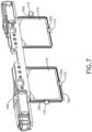
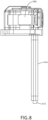
- FIGS. 7 and 8 an exemplary embodiment of a head wearable display device 104 of FIG. 1 according to the inventive concepts disclosed herein is depicted.
- FIG. 7 shows a front perspective view of the head wearable display device 104.
- FIG. 8 shows a side view of the head wearable display device 104.
- FIGS. 7 and 8 show two image monitor sensors 115, with a first image monitor sensor 115 optically coupled to the waveguide 114 along a bottom edge 504 of the waveguide 114 and with the second image monitor sensor 115 optically coupled to the waveguide 114 along a side edge 506 of the waveguide 114.
- the waveguide 114 may include output gratings 704 positioned at the edge of the waveguide 114 where the image monitor sensors 115 are located.
- the side edge 506 and/or the bottom edge 504 of the waveguide 114 is polished in a small area where the image monitor sensor 115 is optically coupled to the waveguide 114 to view the image from the light that makes it to the bottom or side of the waveguide 114.
- the image may have chromatic aberration, but the overall structure of the image can be visualized, such as for the occurrence of an image that is frozen, flipped, rotated etc.
- the edge of the waveguide where the image monitor sensor 115 is located may include a small output grating 704 between the image monitor sensor 115 and the polished edge so as to remove the chromatic aberration in the captured monitored image.
- the image monitor sensors 115 could be placed on both eyes' waveguides 114, in multiple locations and along the sides.
- the wires 702 for the camera can be routed around the frame of the waveguides 114 of the HWD device 104. With an image monitor sensor 115 on both eye systems, the monitored images captured can be compared to determine if one waveguide display 110 has an issue, as the probability of both having an issue at the same time would be very small.
- the image monitor sensors 115 can (1) capture a near 1:1 sample of the image FOV and resolution or, (2) perform a coarse system monitoring similar to a photodiode-type monitor employed in some HUD systems today that only views quadrants of the image to check for stuck/flipped image.
- the captured HWD device 104 image can be compared against data from the HWD image generation system (e.g., computing device 118) to enable fully independent validation of the projected image. This allows the performance of most or all of the key display content monitoring likely required of a high integrity avionics display system to confirm appropriate image content, overall integrity, and commanded brightness.
- the photodiodes in this embodiment could be paired with a brief subframe pulse of a different illumination color or near-infrared (NIR) frequency that is not efficiently coupled into the waveguide 114 and thus is imperceptible to a pilot.
- NIR near-infrared
- the system can monitor for appropriate alignment of presented content with the real world, as well as erroneous masking of areas of the cockpit which should always remain visible to the pilot.
- the image monitor sensor data may be compared with other sources of truth to generate an independent and closed-loop feedback system.
- Video and inertial data from head tracker camera (e.g., sensor 204) and HWD device IMU together with aircraft-fixed video and inertial data from the platform IMU 126 and pilot monitoring camera is available as well as known fiducial locations and cockpit geometry. This information is used to determine the appropriate HWD image alignment in the system.
- a closed loop verification of system integrity can conceivably be performed. This method might be further used to optimize the alignment of the system in real-time or blank portions of the image as needed based on required visibility or erroneous behavior.
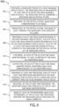
- a step 902 may include providing a waveguide display of a head wearable display device, the waveguide display implemented at least one of in or on the head wearable display device, the waveguide display comprising a waveguide and an optical system.
- a step 904 may include receiving, by the optical system, image data corresponding to an image.
- a step 910 may include capturing, by each of the at least one image monitor sensor, at least a portion of the image as a monitored image.
- a step 912 may include outputting, by each of the at least one image monitor sensor, monitored image data corresponding to the monitored image.
- a step 916 may include receiving, by the at least one processor, the monitored image data from each of the at least one image monitor sensor.
- the method 900 may include any of the operations disclosed throughout.
- At least one non-transitory computer-readable medium may refer to as at least one non-transitory computer-readable medium (e.g., e.g., at least one computer-readable medium implemented as hardware; e.g., at least one non-transitory processor-readable medium, at least one memory (e.g., at least one nonvolatile memory, at least one volatile memory, or a combination thereof; e.g., at least one random-access memory, at least one flash memory, at least one read-only memory (ROM) (e.g., at least one electrically erasable programmable read-only memory (EEPROM)), at least one on-processor memory (e.g., at least one on-processor cache, at least one on-processor buffer, at least one on-processor flash memory, at least one on-processor EEPROM, or a combination thereof), or a combination thereof), at least one storage device (e.g., at least one hard disk drive, or a digital versatile disk drive, or a magnetic tape
- At least one means one or a plurality of; for example, “at least one” may comprise one, two, three, ..., one hundred, or more.
- one or more means one or a plurality of; for example, “one or more” may comprise one, two, three, ... , one hundred, or more.
- zero or more means zero, one, or a plurality of; for example, “zero or more” may comprise zero, one, two, three, ..., one hundred, or more.
- embodiments of the methods according to the inventive concepts disclosed herein may include one or more of the steps described herein. Further, such steps may be carried out in any desired order and two or more of the steps may be carried out simultaneously with one another. Two or more of the steps disclosed herein may be combined in a single step, and in some embodiments, one or more of the steps may be carried out as two or more sub-steps. Further, other steps or sub-steps may be carried in addition to, or as substitutes to one or more of the steps disclosed herein.
- inventive concepts disclosed herein are well adapted to carry out the objects and to attain the advantages mentioned herein as well as those inherent in the inventive concepts disclosed herein. While presently preferred embodiments of the inventive concepts disclosed herein have been described for purposes of this disclosure, it will be understood that numerous changes may be made which will readily suggest themselves to those skilled in the art and which are accomplished within the broad scope and coverage of the inventive concepts disclosed and claimed herein.
Landscapes
- Physics & Mathematics (AREA)
- General Physics & Mathematics (AREA)
- Optics & Photonics (AREA)
- Engineering & Computer Science (AREA)
- Theoretical Computer Science (AREA)
- Human Computer Interaction (AREA)
- General Engineering & Computer Science (AREA)
- Computer Hardware Design (AREA)
- User Interface Of Digital Computer (AREA)
Abstract
Description
- Commercial-off-the-shelf (COTS) devices are frequently used in avionics products due to the high cost of custom devices, but use of such COTS devices is typically challenging due to the system integrity required to mitigate aviation hazards. COTS devices are frequently used to some extent in commercial aviation products in order to be competitive in the marketplace. However, it is inherently difficult to substantiate compliance with Hazardous and Catastrophic aviation hazards when COTS devices are used, because they lack formal DO-254 design assurance evidence.
- Head wearable display (HWD) devices, such as and helmet mounted display (HMD) devices, face challenges related to the use of COTS devices; however, the implementation challenges for monitoring schemes are significant due to the small size and tight integration of head worn components. If future HWDs with COTS components include flight guidance symbology such as the AIII mode used for Category III landing credit and/or vision systems enabling low visibility operations, or if such HWDs are used in single pilot operations (SPO), some form of display path monitoring would likely be required. However, currently, there is no monitoring solution for such HWDs.
- In one aspect, embodiments of the inventive concepts disclosed herein are directed to a system. The system may include a head wearable display device and at least one processor. The head wearable display device may include a waveguide display and at least one image monitor sensor. The waveguide display may be implemented at least one of in or on the head wearable display device. The waveguide display may include a waveguide and an optical system, the optical system configured to: receive image data corresponding to an image; and project the image at least through the waveguide to be displayed to a user. Each of the at least one image monitor sensor may be implemented in or on the head wearable display device. Each of the at least one image monitor sensor may be optically coupled to the waveguide or the optical system of the waveguide display. Each of the at least one image monitor sensor may be configured to: capture at least a portion of the image as a monitored image; and output monitored image data corresponding to the monitored image. Each of the at least one processor may be implemented in the head wearable display device or in a computing device separate from the head wearable display device. The at least one processor may be configured to: receive the monitored image data from each of the at least one image monitor sensor; and based at least on the monitored image data, determine whether the waveguide display displayed the image correctly.
- In a further aspect, embodiments of the inventive concepts disclosed herein are directed to a method. The method may include: providing a waveguide display of a head wearable display device, the waveguide display implemented at least one of in or on the head wearable display device, the waveguide display comprising a waveguide and an optical system; receiving, by the optical system, image data corresponding to an image; projecting, by the optical system, the image at least through the waveguide to be displayed to a user; providing at least one image monitor sensor of the head wearable display device, each of the at least one image monitor sensor implemented in or on the head wearable display device, each of the at least one image monitor sensor optically coupled to the waveguide or the optical system of the waveguide display; capturing, by each of the at least one image monitor sensor, at least a portion of the image as a monitored image; outputting, by each of the at least one image monitor sensor, monitored image data corresponding to the monitored image; providing at least one processor, each of the at least one processor implemented in the head wearable display device or in a computing device separate from the head wearable display device; receiving, by the at least one processor, the monitored image data from each of the at least one image monitor sensor; and based at least on the monitored image data, determining, by the at least one processor, whether the waveguide display displayed the image correctly.
- Implementations of the inventive concepts disclosed herein may be better understood when consideration is given to the following detailed description thereof. Such description makes reference to the included drawings, which are not necessarily to scale, and in which some features may be exaggerated and some features may be omitted or may be represented schematically in the interest of clarity. Like reference numerals in the drawings may represent and refer to the same or similar element, feature, or function. In the drawings:
-
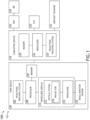
FIG. 1 is a view of an exemplary embodiment of a system including a head wearable display (HWD) device according to the inventive concepts disclosed herein. -
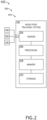
FIG. 2 is a view of the head and/or pose tracking system of the HWD device ofFIG. 1 according to the inventive concepts disclosed herein. -
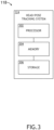
FIG. 3 is a view of the head and/or pose tracking system of the computing device ofFIG. 1 according to the inventive concepts disclosed herein. -
FIG. 4 is a view of the enhanced vision system of the system ofFIG. 1 according to the inventive concepts disclosed herein. -
FIG. 5 is a view of an exemplary embodiment of the HWD device ofFIG. 1 according to the inventive concepts disclosed herein. -
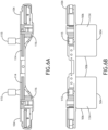
FIG. 6A is a view of an exemplary embodiment of the HWD device ofFIG. 1 according to the inventive concepts disclosed herein. -
FIG. 6B is a view of an exemplary embodiment of the HWD device ofFIG. 1 according to the inventive concepts disclosed herein. -
FIG. 7 is a view of an exemplary embodiment of the HWD device ofFIG. 1 according to the inventive concepts disclosed herein. -
FIG. 8 is a view of an exemplary embodiment of the HWD device ofFIG. 1 according to the inventive concepts disclosed herein. -
FIG. 9 is a diagram of an exemplary embodiment of a method according to the inventive concepts disclosed herein. - Before explaining at least one embodiment of the inventive concepts disclosed herein in detail, it is to be understood that the inventive concepts are not limited in their application to the details of construction and the arrangement of the components or steps or methodologies set forth in the following description or illustrated in the drawings. In the following detailed description of embodiments of the instant inventive concepts, numerous specific details are set forth in order to provide a more thorough understanding of the inventive concepts. However, it will be apparent to one of ordinary skill in the art having the benefit of the instant disclosure that the inventive concepts disclosed herein may be practiced without these specific details. In other instances, well-known features may not be described in detail to avoid unnecessarily complicating the instant disclosure. The inventive concepts disclosed herein are capable of other embodiments or of being practiced or carried out in various ways. Also, it is to be understood that the phraseology and terminology employed herein is for the purpose of description and should not be regarded as limiting.
- As used herein a letter following a reference numeral is intended to reference an embodiment of the feature or element that may be similar, but not necessarily identical, to a previously described element or feature bearing the same reference numeral (e.g., 1, 1a, 1b). Such shorthand notations are used for purposes of convenience only, and should not be construed to limit the inventive concepts disclosed herein in any way unless expressly stated to the contrary.
- Further, unless expressly stated to the contrary, "or" refers to an inclusive or and not to an exclusive or. For example, a condition A or B is satisfied by anyone of the following: A is true (or present) and B is false (or not present), A is false (or not present) and B is true (or present), and both A and B are true (or present).
- In addition, use of the "a" or "an" are employed to describe elements and components of embodiments of the instant inventive concepts. This is done merely for convenience and to give a general sense of the inventive concepts, and "a" and "an" are intended to include one or at least one and the singular also includes the plural unless it is obvious that it is meant otherwise.
- Finally, as used herein any reference to "one embodiment," or "some embodiments" means that a particular element, feature, structure, or characteristic described in connection with the embodiment is included in at least one embodiment of the inventive concepts disclosed herein. The appearances of the phrase "in some embodiments" in various places in the specification are not necessarily all referring to the same embodiment, and embodiments of the inventive concepts disclosed may include one or more of the features expressly described or inherently present herein, or any combination of sub-combination of two or more such features, along with any other features which may not necessarily be expressly described or inherently present in the instant disclosure.
- Broadly, embodiments of the inventive concepts disclosed herein are directed to a method and a system including a head wearable device having a waveguide display and an image monitor sensor (e.g., a camera or a photodiode).
- HWD display devices, such as glasses HWD display devices or HMD display devices, are very small and tightly packaged with other optical elements due to the size and weight requirements of head worn technology. Further complicating this challenge is the desire to use COTS technology with minimal customization to limit development costs to a competitive level. Therefore, an external monitoring solution is highly desirable as compared to multiple discrete, embedded monitors used for head-up display (HUD) monitoring schemes.
- Many common near-eye display devices on the market employ optical waveguide technology to translate an image from projection optics to a viewing region in front of an eye. In addition to translating the image to a location for viewing, the waveguide has a unique feature that enlarges the image to an appropriate size for viewing, enabling the use of much smaller projection and display components. A monitoring concept of some embodiments relies on a feature in many waveguide optical systems which presents a "pre-expanded" and collimated image at a location that can be captured by a small image monitor sensor, such as a small camera or photodiode(s).
- Referring now to
FIGS. 1 ,2 ,3 ,4 ,5 ,6A ,6B ,7 , and8 , an exemplary embodiment of asystem 100 according to the inventive concepts disclosed herein is depicted. Thesystem 100 may be implemented as any suitable system, such as at least one vehicle (e.g., an aircraft 102). For example, as shown inFIG. 1 , thesystem 100 may include anaircraft 102. For example, theaircraft 102 may include anaircraft cockpit 200, at least oneHWD device 104, at least onecomputing device 118, at least one inertial measurement unit (IMU) 126, at least one inertial reference system (IRS) 128, optionally at least one enhanced vision system (EVS) 130, andaircraft sensors 132, some or all of which may be communicatively coupled at any given time. - In some embodiments, the
HWD device 104 may include at least one head and/orpose tracking system 106, at least oneprocessor 108, at least onememory device 109, at least onewaveguide display 110, and/or at least one image monitor sensor 115 (e.g., a camera or a photodiode(s)), some or all of which may be optically and/or communicatively coupled at any given time. For example, thewaveguide display 110 may include at least oneoptical system 112, at least onewaveguide 114, and/or the at least oneimage monitor sensor 115, some or all of which may be optically and/or communicatively coupled at any given time. In some embodiments, theHWD device 104 may be in theaircraft cockpit 200. - The head and/or pose
tracking system 106 may have optical, magnetic, and/or inertial tracking capability. In some embodiments, the head and/or posetracking system 106 may include head and/or pose tracking capabilities and/or be coordinated with head and/or pose tracking capabilities of another head and/or pose tracking system (e.g., 124), for example, such that the head and/or pose tracking operations are relative to a position and/or orientation of a user and/or relative to a position and/or orientation to a vehicle (e.g., the aircraft 102). For example, the head and/or posetracking system 106 may be configured to track the Line of Sight (LOS) of thewaveguide display 110 optical system. For example, if thewaveguide display 110 is mounted to theHWD device 104, this direction may be a direction that a head is pointing that is being tracked. The head and/or posetracking system 106 may include at least one sensor 204 (e.g., a camera configured to capture locations of cockpit reference fiducials 202), at least one processor 206, at least onememory device 208, and/or at least one storage device 210 (e.g., at least one non-volatile storage device), as well as other components, equipment, and/or devices commonly included in a head and/or pose tracking system, some or all of which may be communicatively coupled at any time, as shown inFIG. 2 . The at least one processor 206 may be implemented as any suitable processor(s), such as at least one general purpose processor, at least one central processing unit (CPU), at least one image processor, at least one graphics processing unit (GPU), at least one field-programmable gate array (FPGA), and/or at least one special purpose processor configured to execute instructions for performing (e.g., collectively performing if more than one processor) any or all of the operations disclosed throughout. The at least one sensor 204 may be at least one optical sensor (e.g., an optical infrared sensor (e.g., an infrared camera) configured to detect infrared light emitted and/or reflected from the fiducials 202), at least one magnetic sensor, and/or at least one inertial sensor. The head and/or posetracking system 106 may be configured to determine and track a position and an orientation of a user's head relative to an environment (e.g., a cockpit 200). The head and/or posetracking system 106 may be configured for performing fully automatic head and/or pose tracking operations in real time. The processor 206 of the head and/or posetracking system 106 may be configured to process data received from the sensors 204 and output processed data (e.g., head and/or pose tracking data) to one of the computing devices of thesystem 100 and/or theprocessor 108 for use in generating images aligned with the user's field of view, such as augmented reality or virtual reality images aligned with the user's field of view to be displayed by thewaveguide display 110. For example, the processor 206 may be configured to determine and track a position and orientation of a user's head relative to an environment (e.g., a cockpit 200). Additionally, for example, the processor 206 may be configured to generate position and orientation data associated with such determined information and output the generated position and orientation data. The processor 206 may be configured to run various software applications or computer code stored in a non-transitory computer-readable medium (e.g.,memory 208 and/or storage device 210) and configured to execute various instructions or operations. In some embodiments, the at least one processor 206 may be implemented as a special purpose processor configured to execute instructions for performing (e.g., collectively performing if more than one processor) any or all of the operations disclosed throughout. - The at least one
processor 108 may be implemented as any suitable processor(s), such as at least one general purpose processor, at least one central processing unit (CPU), at least one image processor, at least one graphics processing unit (GPU), and/or at least one special purpose processor configured to execute instructions for performing (e.g., collectively performing if more than one processor) any or all of the operations disclosed throughout. In some embodiments, theprocessor 108 may be communicatively coupled to thewaveguide display 110. For example, theprocessor 108 may be configured to: receive head and/or pose system tracking data; receive image data from thecomputing device 118; generate and/or output image data to thewaveguide display 110 and/or to theoptical system 112, for example, based on and/or the head and/or pose tracking system data; generate and/or output augmented reality and/or virtual reality image data towaveguide display 110 and/or theoptical system 112, for example, based on and/or the head and/or pose tracking system data; and/or generate and/or output other image data, which may include vehicle operation (e.g., aircraft) information, symbology, navigation information, tactical information, and/or sensor information to thewaveguide display 110 and/or theoptical system 112, for example, based on the head and/or pose tracking system data. - For example, the
processor 108 may be configured to: receive the monitored image data from each of the at least oneimage monitor sensor 115; and/or based at least on the monitored image data, determine whether thewaveguide display 110 displayed the image correctly. - For example, the
processor 108 may be configured to: obtain the image data corresponding to the image; compare the monitored image of each of the at least oneimage monitor sensor 115 against the image; and/or based at least on the comparison of the monitored image of each of the at least one image monitor sensor against the image, determine whether the givenwaveguide display 110 displayed the image correctly. - For example, the
processor 108 may be configured to: based at least on the monitored image data, determine that thewaveguide display 110 displayed the image incorrectly. For example, theprocessor 108 may be configured to: based at least on the monitored image data, determine that thewaveguide display 110 displayed the image as a flipped image or a frozen image. For example, theprocessor 108 may be configured to: based at least on the monitored image data, determine that thewaveguide display 110 displayed the image brighter than a predetermined maximum brightness threshold or less bright than a predetermined minimum brightness threshold. For example, theprocessor 108 may be configured to: based at least on the monitored image data, determine that thewaveguide display 110 displayed the image with incorrectly positioned symbology, incorrect symbology, or missing symbology. For example, theprocessor 108 may be configured to: based at least on the monitored image data, determine that thewaveguide display 110 displayed image content of the image incorrectly. For example, theprocessor 108 may be configured to: based at least on the determination that thewaveguide display 110 displayed the image incorrectly, disable the givenwaveguide display 110. For example, theprocessor 108 may be configured to: determine whether at least one of the monitored image of each of the a least oneimage monitor sensor 115 is aligned with a field of view of the user. - For example, the
processor 108 may be configured to: compare the monitored image data against the second waveguide monitored image; and based at least on the comparison of the monitored image data against the second waveguide monitored image data, determine whether one of thewaveguide display 110 or thesecond waveguide display 110 displayed the image incorrectly. - The
waveguide display 110 may be implemented as any suitable waveguide display. Thewaveguide display 110 may be implemented in or on the headwearable display device 104. Thewaveguide display 110 may include the at least oneoptical system 112 and/or at least onewaveguide 114. For example, theoptical system 112 may include at least one processor, at least one collimator, and/or at leastprojector 116. Theoptical system 112 may be configured to: receive image data corresponding to an image; and/or project images at least through thewaveguide 114 to be displayed to the user. In some embodiments, thewaveguide 116 may be a diffractive, mirror, or beam splitter based waveguide. In some embodiments, the waveguide display 111 may include at least one lens, at least one mirror, diffraction gratings, at least one polarization sensitive component, at least one beam splitter, at least onewaveguide 114, at least one light pipe, at least one window, and/or theprojector 116. - The
optical system 112 may be configured to receive image data from theprocessor 108 and project images through thewaveguide 114 for display to the user. - Each of the at least one
image monitor sensor 115 may be any suitable image sensor, such as a camera, transparent imager, or a photodiode(s). Each of the at least oneimage monitor sensor 115 may be implemented in or on the head wearable display device. Each of the at least oneimage monitor sensor 115 may be optically coupled to thewaveguide 114 and/or theoptical system 112 of thewaveguide display 110. Each of the at least oneimage monitor sensor 115 may be configured to: capture at least a portion of the image as a monitored image; and/or output monitored image data corresponding to the monitored image. - In some embodiments, a given
image monitor sensor 115 may be optically coupled to thewaveguide 114 at a position on thewaveguide 114 above a user-viewable portion of thewaveguide 114, wherein the givenimage monitor sensor 115 is configured to capture at least the at least the portion of the image emitted from the position on thewaveguide 114 above the user-viewable portion of thewaveguide 114. - In some embodiments, a given
image monitor sensor 115 may be optically coupled to thewaveguide 114 at a position along aside edge 506 or abottom edge 504 of the waveguide. For example, thewaveguide 114 may include an output grating 704 between the givenimage monitor sensor 115 and theside edge 506 or thebottom edge 506 of thewaveguide 114, for example, to reduce chromatic aberration in the monitored image. - In some embodiments, the head
wearable display device 104 may include asecond waveguide display 110 including asecond waveguide 114 and a secondoptical system 112, wherein the secondoptical system 112 is configured to: receive the image data corresponding to the image and project the image at least through the second waveguide to be displayed to the user. In some embodiments, thewaveguide display 110 is one of a left eye waveguide display or a right eye waveguide display, wherein thesecond waveguide display 110 is another of the left eye waveguide display or the right eye waveguide display. In some embodiments, the headwearable display device 104 further includes at least one secondimage monitor sensor 115, each of the at least one secondimage monitor sensor 115 optically coupled to thesecond waveguide 114 or the secondoptical system 112 of thesecond waveguide display 110, each of the at least one secondimage monitor sensor 115 configured to: capture at least a portion of the image as a second waveguide monitored image and output second waveguide monitored image data corresponding to the second waveguide monitored image. In some embodiments, the at least one processor (e.g., 108 and/or 122) may be further configured to: compare the monitored image data against the second waveguide monitored image; and based at least on the comparison of the monitored image data against the second waveguide monitored image data, determine whether one of thewaveguide display 110 or thesecond waveguide display 110 displayed the image incorrectly. - In some embodiments, the at least one
image monitor sensor 115 includes twoimage monitor sensors 115, wherein each of the two image monitor sensors are positioned at different locations on thewaveguide 114. For example, each of the twoimage monitor sensors 115 may be configured to capture different portions of the image. - The
computing device 118 may be implemented as any suitable computing device, such as an avionics computing device. Thecomputing device 118 may include at least onememory 120, at least oneprocessor 122, and/or at least one head and/or posetracking system 124, some or all of which may be communicatively coupled at any given time. - The at least one
processor 122 may be implemented as any suitable processor(s), such as at least one general purpose processor, at least one central processing unit (CPU), at least one image processor, at least one graphics processing unit (GPU), and/or at least one special purpose processor configured to execute instructions for performing (e.g., collectively performing if more than one processor) any or all of the operations disclosed throughout. For example, theprocessor 122 may be configured to: receive IMU data from theIMU 126 and/or IRS data from theIRS 128; receive EVS image data from the EVS 130 (which may include at least oneprocessor 402 and at least onememory device 404 as shown inFIG. 4 ); and/or receive aircraft sensor data from theaircraft sensors 132; receive head and/or pose system tracking data; generate and/or output image data to thewaveguide display 110 and/or to theoptical system 112, for example, based on and/or the head and/or pose tracking system data; generate and/or output augmented reality and/or virtual reality image data towaveguide display 110 and/or theoptical system 112, for example, based on and/or the head and/or pose tracking system data; and/or generate and/or output other image data, which may include vehicle operation (e.g., aircraft) information, symbology, navigation information, tactical information, and/or sensor information to thewaveguide display 110 and/or theoptical system 112, for example, based on the head and/or pose tracking system data. - For example, the
processor 122 may be configured to: receive the monitored image data from each of the at least oneimage monitor sensor 115; and/or based at least on the monitored image data, determine whether thewaveguide display 110 displayed the image correctly. - For example, the
processor 122 may be configured to: obtain the image data corresponding to the image; compare the monitored image of each of the at least oneimage monitor sensor 115 against the image; and/or based at least on the comparison of the monitored image of each of the at least one image monitor sensor against the image, determine whether the givenwaveguide display 110 displayed the image correctly. - For example, the
processor 122 may be configured to: based at least on the monitored image data, determine that thewaveguide display 110 displayed the image incorrectly. For example, theprocessor 122 may be configured to: based at least on the monitored image data, determine that thewaveguide display 110 displayed the image as a flipped image or a frozen image. For example, theprocessor 122 may be configured to: based at least on the monitored image data, determine that thewaveguide display 110 displayed the image brighter than a predetermined maximum brightness threshold or less bright than a predetermined minimum brightness threshold. For example, theprocessor 122 may be configured to: based at least on the monitored image data, determine that thewaveguide display 110 displayed the image with incorrectly positioned symbology, incorrect symbology, or missing symbology. For example, theprocessor 122 may be configured to: based at least on the monitored image data, determine that thewaveguide display 110 displayed image content of the image incorrectly. For example, theprocessor 122 may be configured to: based at least on the determination that thewaveguide display 110 displayed the image incorrectly, disable the givenwaveguide display 110. For example, theprocessor 122 may be configured to: determine whether at least one of the monitored image of each of the a least oneimage monitor sensor 115 is aligned with a field of view of the user. - For example, the
processor 122 may be configured to: compare the monitored image data against the second waveguide monitored image; and based at least on the comparison of the monitored image data against the second waveguide monitored image data, determine whether one of thewaveguide display 110 or thesecond waveguide display 110 displayed the image incorrectly. - The head and/or pose
tracking system 124 may have optical, magnetic, and/or inertial tracking capability. In some embodiments, the head and/or posetracking system 124 may include head and/or pose tracking capabilities and/or be coordinated with head and/or pose tracking capabilities of another head and/or pose tracking system (e.g., 106), for example, such that the head and/or pose tracking operations are relative to a position and/or orientation of a user and/or relative to a position and/or orientation to a vehicle (e.g., the aircraft 102). For example, the head and/or posetracking system 124 may be configured to track a direction of where a field of view (FOV) through thewaveguide display 110 is pointing. For example, if thewaveguide display 110 is mounted to theHWD device 104, this direction may be a direction that a head is pointing that is being tracked. The head and/or posetracking system 106 may include at least one sensor (not shown), at least oneprocessor 302, at least onememory 306, and/or at least one storage device 308, as well as other components, equipment, and/or devices commonly included in a head and/or pose tracking system, some or all of which may be communicatively coupled at any time, as shown inFIG. 3 . The at least oneprocessor 302 may be implemented as any suitable processor(s), such as at least one general purpose processor, at least one central processing unit (CPU), at least one image processor, at least one graphics processing unit (GPU), at least one field-programmable gate array (FPGA), and/or at least one special purpose processor configured to execute instructions for performing (e.g., collectively performing if more than one processor) any or all of the operations disclosed throughout. The at least one sensor may be at least one optical sensor (e.g., an optical infrared sensor (e.g., an infrared camera) configured to detect infrared light emitted and/or reflected from the fiducials 202), at least one magnetic sensor, and/or at least one inertial sensor. The head and/or posetracking system 124 may be configured to determine and track a position and an orientation of a user's head relative to an environment (e.g., a cockpit 200). The head and/or posetracking system 106 may be configured for performing fully automatic head and/or pose tracking operations in real time. Theprocessor 302 of the head and/or posetracking system 124 may be configured to process data received from the sensors 204 and output processed data (e.g., head and/or pose tracking data) to one of the computing devices of thesystem 100 and/or theprocessor 108 for use in generating images aligned with the user's field of view, such as augmented reality or virtual reality images aligned with the user's field of view to be displayed by thewaveguide display 110. For example, theprocessor 302 may be configured to determine and track a position and orientation of a user's head relative to an environment (e.g., a cockpit 200). Theprocessor 302 may be configured to receive IMU data from theIMU 126 and/or IRS data from theIRS 128. Additionally, for example, theprocessor 302 may be configured to generate position and orientation data associated with such determined information and output the generated position and orientation data. Theprocessor 302 may be configured to run various software applications or computer code stored in a non-transitory computer-readable medium (e.g.,memory 304 and/or storage device 306) and configured to execute various instructions or operations. In some embodiments, the at least oneprocessor 302 may be implemented as a special purpose processor configured to execute instructions for performing (e.g., collectively performing if more than one processor) any or all of the operations disclosed throughout. - In some embodiments, at least one processor (e.g., 108 and/or 122), each of the at least one processor (e.g., 108 and/or 122) implemented in the head
wearable display device 104 or in acomputing device 118 separate from the headwearable display device 104, wherein the at least one processor (e.g., 108 and/or 122) is configured (e.g., collectively configured to perform, if more than one processor) to any of the operations disclosed throughout. For example, the at least one processor may be at least two processors including at least one head wearabledisplay device processor 108 and at least one at least onecomputing device processor 122 collectively configured to perform any or all of the operations disclosed throughout. - Referring now to
FIGS. 5 ,6A, and 6B , an exemplary embodiment of a headwearable display device 104 ofFIG. 1 worn by a user 502 (e.g., a pilot) according to the inventive concepts disclosed herein is depicted.FIG. 5 shows a side view of the headwearable display device 104.FIG. 6A shows a top view of the headwearable display device 104.FIG. 6B shows a front view of the headwearable display device 104.FIGS. 5 ,6A, and 6B show twoimage monitor sensors 115, each optically coupled to thewaveguide 114 at a position on thewaveguide 114 above a user-viewable portion of thewaveguide 114. Eachimage monitor sensor 115 is configured to capture at least the at least the portion of the image emitted from the position on thewaveguide 114 above the user-viewable portion of thewaveguide 114. Light from theoptical system 112 may enters thewaveguide 114 and is not fully captured within thewaveguide 114, leaving a portion of the light to pass through the waveguide to be captured by theimage monitor sensor 115. - Referring now to
FIGS. 7 and8 , an exemplary embodiment of a headwearable display device 104 ofFIG. 1 according to the inventive concepts disclosed herein is depicted.FIG. 7 shows a front perspective view of the headwearable display device 104.FIG. 8 shows a side view of the headwearable display device 104.FIGS. 7 and8 show twoimage monitor sensors 115, with a firstimage monitor sensor 115 optically coupled to thewaveguide 114 along abottom edge 504 of thewaveguide 114 and with the secondimage monitor sensor 115 optically coupled to thewaveguide 114 along aside edge 506 of thewaveguide 114. In some embodiments, thewaveguide 114 may includeoutput gratings 704 positioned at the edge of thewaveguide 114 where theimage monitor sensors 115 are located. In some embodiments, theside edge 506 and/or thebottom edge 504 of thewaveguide 114 is polished in a small area where theimage monitor sensor 115 is optically coupled to thewaveguide 114 to view the image from the light that makes it to the bottom or side of thewaveguide 114. The image may have chromatic aberration, but the overall structure of the image can be visualized, such as for the occurrence of an image that is frozen, flipped, rotated etc. In some embodiments, the edge of the waveguide where theimage monitor sensor 115 is located may include a small output grating 704 between theimage monitor sensor 115 and the polished edge so as to remove the chromatic aberration in the captured monitored image. The image monitorsensors 115 could be placed on both eyes'waveguides 114, in multiple locations and along the sides. Thewires 702 for the camera can be routed around the frame of thewaveguides 114 of theHWD device 104. With animage monitor sensor 115 on both eye systems, the monitored images captured can be compared to determine if onewaveguide display 110 has an issue, as the probability of both having an issue at the same time would be very small. - In some embodiments, the
image monitor sensors 115 can (1) capture a near 1:1 sample of the image FOV and resolution or, (2) perform a coarse system monitoring similar to a photodiode-type monitor employed in some HUD systems today that only views quadrants of the image to check for stuck/flipped image. For the first example (1), it enables the use of machine vision algorithms to extract specific symbols and their position on thewaveguide display 110. In this embodiment, the capturedHWD device 104 image can be compared against data from the HWD image generation system (e.g., computing device 118) to enable fully independent validation of the projected image. This allows the performance of most or all of the key display content monitoring likely required of a high integrity avionics display system to confirm appropriate image content, overall integrity, and commanded brightness. For the second example (2), it may be much simpler to implement as it could be realized with small photodiodes and a mask over the back side of input grating. The photodiodes in this embodiment could be paired with a brief subframe pulse of a different illumination color or near-infrared (NIR) frequency that is not efficiently coupled into thewaveguide 114 and thus is imperceptible to a pilot. - In some embodiments, utilizing processing, the system can monitor for appropriate alignment of presented content with the real world, as well as erroneous masking of areas of the cockpit which should always remain visible to the pilot. In this case, the image monitor sensor data may be compared with other sources of truth to generate an independent and closed-loop feedback system. Video and inertial data from head tracker camera (e.g., sensor 204) and HWD device IMU together with aircraft-fixed video and inertial data from the
platform IMU 126 and pilot monitoring camera is available as well as known fiducial locations and cockpit geometry. This information is used to determine the appropriate HWD image alignment in the system. By comparing the final as-presented image against an independently calculated assessment of proper alignment, a closed loop verification of system integrity can conceivably be performed. This method might be further used to optimize the alignment of the system in real-time or blank portions of the image as needed based on required visibility or erroneous behavior. - Referring now to
FIG. 9 , an exemplary embodiment of amethod 900 according to the inventive concepts disclosed herein may include one or more of the following steps. Additionally, for example, some embodiments may include performing one more instances of themethod 900 iteratively, concurrently, and/or sequentially. Additionally, for example, at least some of the steps of themethod 900 may be performed in parallel and/or concurrently. Additionally, in some embodiments, at least some of the steps of themethod 900 may be performed non-sequentially. Additionally, in some embodiments, at least some of the steps of themethod 900 may be performed in sub-steps of providing various components. - A
step 902 may include providing a waveguide display of a head wearable display device, the waveguide display implemented at least one of in or on the head wearable display device, the waveguide display comprising a waveguide and an optical system. - A
step 904 may include receiving, by the optical system, image data corresponding to an image. - A
step 906 may include projecting, by the optical system, the image at least through the waveguide to be displayed to a user. - A
step 908 may include providing at least one image monitor sensor of the head wearable display device, each of the at least one image monitor sensor implemented in or on the head wearable display device, each of the at least one image monitor sensor optically coupled to the waveguide or the optical system of the waveguide display. - A
step 910 may include capturing, by each of the at least one image monitor sensor, at least a portion of the image as a monitored image. - A
step 912 may include outputting, by each of the at least one image monitor sensor, monitored image data corresponding to the monitored image. - A
step 914 may include providing at least one processor, each of the at least one processor implemented in the head wearable display device or in a computing device separate from the head wearable display device. - A
step 916 may include receiving, by the at least one processor, the monitored image data from each of the at least one image monitor sensor. - A
step 918 may include based at least on the monitored image data, determining, by the at least one processor, whether the waveguide display displayed the image correctly. - Further, the
method 900 may include any of the operations disclosed throughout. - As will be appreciated from the above, embodiments of the inventive concepts disclosed herein may be directed to a method and a system including a head wearable device having a waveguide display and an image monitor sensor (e.g., a camera or a photodiode).
- As used throughout and as would be appreciated by those skilled in the art, "at least one non-transitory computer-readable medium" may refer to as at least one non-transitory computer-readable medium (e.g., e.g., at least one computer-readable medium implemented as hardware; e.g., at least one non-transitory processor-readable medium, at least one memory (e.g., at least one nonvolatile memory, at least one volatile memory, or a combination thereof; e.g., at least one random-access memory, at least one flash memory, at least one read-only memory (ROM) (e.g., at least one electrically erasable programmable read-only memory (EEPROM)), at least one on-processor memory (e.g., at least one on-processor cache, at least one on-processor buffer, at least one on-processor flash memory, at least one on-processor EEPROM, or a combination thereof), or a combination thereof), at least one storage device (e.g., at least one hard-disk drive, at least one tape drive, at least one solid-state drive, at least one flash drive, at least one readable and/or writable disk of at least one optical drive configured to read from and/or write to the at least one readable and/or writable disk, or a combination thereof), or a combination thereof).
- As used throughout, "at least one" means one or a plurality of; for example, "at least one" may comprise one, two, three, ..., one hundred, or more. Similarly, as used throughout, "one or more" means one or a plurality of; for example, "one or more" may comprise one, two, three, ... , one hundred, or more. Further, as used throughout, "zero or more" means zero, one, or a plurality of; for example, "zero or more" may comprise zero, one, two, three, ..., one hundred, or more.
- In the present disclosure, the methods, operations, and/or functionality disclosed may be implemented as sets of instructions or software readable by a device. Further, it is understood that the specific order or hierarchy of steps in the methods, operations, and/or functionality disclosed are examples of exemplary approaches. Based upon design preferences, it is understood that the specific order or hierarchy of steps in the methods, operations, and/or functionality can be rearranged while remaining within the scope of the inventive concepts disclosed herein. The accompanying claims may present elements of the various steps in a sample order, and are not necessarily meant to be limited to the specific order or hierarchy presented.
- It is to be understood that embodiments of the methods according to the inventive concepts disclosed herein may include one or more of the steps described herein. Further, such steps may be carried out in any desired order and two or more of the steps may be carried out simultaneously with one another. Two or more of the steps disclosed herein may be combined in a single step, and in some embodiments, one or more of the steps may be carried out as two or more sub-steps. Further, other steps or sub-steps may be carried in addition to, or as substitutes to one or more of the steps disclosed herein.
- From the above description, it is clear that the inventive concepts disclosed herein are well adapted to carry out the objects and to attain the advantages mentioned herein as well as those inherent in the inventive concepts disclosed herein. While presently preferred embodiments of the inventive concepts disclosed herein have been described for purposes of this disclosure, it will be understood that numerous changes may be made which will readily suggest themselves to those skilled in the art and which are accomplished within the broad scope and coverage of the inventive concepts disclosed and claimed herein.
Claims (15)
- A system, comprising:a head wearable display device (104), comprising:a waveguide display (110) implemented at least one of in or on the head wearable display device, the waveguide display comprising:a waveguide (114); andan optical system (112), the optical system configured to:receive image data corresponding to an image; andproject the image at least through the waveguide to be displayed to a user; andat least one image monitor sensor (115), each of the at least one image monitor sensor (115) implemented in or on the head wearable display device, each of the at least one image monitor sensor (115) optically coupled to the waveguide (114) or the optical system (112) of the waveguide display, each of the at least one image monitor sensor (115) configured to:capture at least a portion of the image as a monitored image; andoutput monitored image data corresponding to the monitored image; andat least one processor (108), each of the at least one processor implemented in the head wearable display device (104) or in a computing device (118) separate from the head wearable display device, wherein the at least one processor (108) is configured to:receive the monitored image data from each of the at least one image monitor sensor; andbased at least on the monitored image data, determine whether the waveguide display displayed the image correctly.
- The system of claim 1, wherein the at least one processor (108) is further configured to: obtain the image data corresponding to the image; compare the monitored image of each of the at least one image monitor sensor against the image; and based at least on the comparison of the monitored image of each of the at least one image monitor sensor against the image, determine whether the given waveguide display displayed the image correctly.
- The system of claim 1, or 2 wherein the at least one processor (108) is further configured to: based at least on the monitored image data, determine that the waveguide display displayed the image incorrectly.
- The system of claim 3, wherein the at least one processor (108) is further configured to: based at least on the monitored image data, determine that the waveguide display displayed the image as a flipped image or a frozen image.
- The system of claim 3, wherein the at least one processor (108) is further configured to: based at least on the monitored image data, determine that the waveguide display displayed the image brighter than a predetermined maximum brightness threshold or less bright than a predetermined minimum brightness threshold.
- The system of claim 3, wherein the at least one processor (108) is further configured to: based at least on the monitored image data, determine that the waveguide display displayed the image with incorrectly positioned symbology, incorrect symbology, or missing symbology.
- The system of claim 3, wherein the at least one processor (108) is further configured to: based at least on the monitored image data, determine that the waveguide display displayed image content of the image incorrectly; and/or
wherein the at least one processor (108) is further configured to: based at least on the determination that the waveguide display displayed the image incorrectly, disable the given waveguide display. - The system of any preceding claim, wherein the at least one processor (108) is further configured to: determine whether at least one of the monitored image of each of the a least one image monitor sensor is aligned with a field of view of the user.
- The system of any preceding claim, wherein the at least one image monitor sensor (115) comprises a given image monitor sensor, wherein the given image monitor sensor is optically coupled to the waveguide (114) at a position on the waveguide above a user-viewable portion of the waveguide (114), wherein the given image monitor sensor is configured to capture at least the at least the portion of the image emitted from the position on the waveguide above the user-viewable portion of the waveguide.
- The system of any preceding claim, wherein the at least one image monitor sensor (115) comprises a given image monitor sensor, wherein the given image monitor sensor is optically coupled to the waveguide (114) at a position along a side edge or a bottom edge of the waveguide (114), and preferably wherein the waveguide (114) includes an output grating between the given image monitor sensor and the side edge or the bottom edge of the waveguide to reduce chromatic aberration in the monitored image.
- The system of any preceding claim, wherein the head wearable display device further comprises a second waveguide display (110), the second waveguide display comprising a second waveguide (114) and a second optical system (112), wherein the second optical system is configured to: receive the image data corresponding to the image and project the image at least through the second waveguide to be displayed to the user, and preferably wherein the waveguide display (110) is one of a left eye waveguide display or a right eye waveguide display, wherein the second waveguide display (110) is another of the left eye waveguide display or the right eye waveguide display, and preferably wherein the head wearable display device further comprises at least one second image monitor sensor (115), each of the at least one second image monitor sensor optically coupled to the second waveguide (114) or the second optical system of the second waveguide display, each of the at least one second image monitor sensor (115) configured to: capture at least a portion of the image as a second waveguide monitored image and output second waveguide monitored image data corresponding to the second waveguide monitored image, and more preferably wherein the at least one processor (108) is further configured to: compare the monitored image data against the second waveguide monitored image; and based at least on the comparison of the monitored image data against the second waveguide monitored image data, determine whether one of the waveguide display or the second waveguide display displayed the image incorrectly.
- The system of any preceding claim, wherein the at least one image monitor sensor (115) comprises two image monitor sensors, wherein each of the two image monitor sensors are positioned at different locations on the waveguide, wherein each of the two image monitor sensors are configured to capture different portions of the image.
- The system of any preceding claim, further comprising the computing device (118) comprising at least one computing device processor, wherein the head wearable display device comprises at least one head wearable display device processor, wherein the at least one processor is at least two processors, wherein the at least two processors comprise the at least one computing device processor and the at least one head wearable display device processor.
- The system of any preceding claim, further comprising an aircraft cockpit, wherein the head wearable display device is in the aircraft cockpit.
- A method, comprising:providing a waveguide display of a head wearable display device, the waveguide display implemented at least one of in or on the head wearable display device, the waveguide display comprising a waveguide and an optical system;receiving, by the optical system, image data corresponding to an image;projecting, by the optical system, the image at least through the waveguide to be displayed to a user;providing at least one image monitor sensor of the head wearable display device, each of the at least one image monitor sensor implemented in or on the head wearable display device, each of the at least one image monitor sensor optically coupled to the waveguide or the optical system of the waveguide display;capturing, by each of the at least one image monitor sensor, at least a portion of the image as a monitored image;outputting, by each of the at least one image monitor sensor, monitored image data corresponding to the monitored image;providing at least one processor, each of the at least one processor implemented in the head wearable display device or in a computing device separate from the head wearable display device;receiving, by the at least one processor, the monitored image data from each of the at least one image monitor sensor; andbased at least on the monitored image data, determining, by the at least one processor, whether the waveguide display displayed the image correctly.
Applications Claiming Priority (1)
| Application Number | Priority Date | Filing Date | Title |
|---|---|---|---|
| US17/847,757 US12436386B2 (en) | 2022-06-23 | 2022-06-23 | Head wearable display device with image monitoring comprising at least one image monitor sensor optically coupled to a waveguide |
Publications (1)
| Publication Number | Publication Date |
|---|---|
| EP4296758A1 true EP4296758A1 (en) | 2023-12-27 |
Family
ID=86896097
Family Applications (1)
| Application Number | Title | Priority Date | Filing Date |
|---|---|---|---|
| EP23179899.2A Pending EP4296758A1 (en) | 2022-06-23 | 2023-06-16 | Head wearable display device with image monitoring |
Country Status (2)
| Country | Link |
|---|---|
| US (1) | US12436386B2 (en) |
| EP (1) | EP4296758A1 (en) |
Families Citing this family (2)
| Publication number | Priority date | Publication date | Assignee | Title |
|---|---|---|---|---|
| US12248146B1 (en) * | 2024-02-12 | 2025-03-11 | Rockwell Collins, Inc. | System and method for monitoring head-up display (HUD) for malfunction |
| WO2026082161A1 (en) * | 2024-10-17 | 2026-04-23 | 烟台睿创微纳技术股份有限公司 | Optical waveguide camera and optical system |
Citations (7)
| Publication number | Priority date | Publication date | Assignee | Title |
|---|---|---|---|---|
| US9766465B1 (en) * | 2014-03-25 | 2017-09-19 | Rockwell Collins, Inc. | Near eye display system and method for display enhancement or redundancy |
| US20180098056A1 (en) * | 2016-10-03 | 2018-04-05 | Microsoft Technology Licensing, Llc | Automatic Detection and Correction of Binocular Misalignment in a Display Device |
| US10109054B1 (en) * | 2016-07-19 | 2018-10-23 | Rockwell Collins, Inc. | Monitoring COTS display devices for HWD/HUD/EVS via transparent photodetectors and imagers |
| CN110660036A (en) * | 2019-11-01 | 2020-01-07 | 长春理工大学 | Image distortion correction method of near-to-eye display system |
| WO2020176240A1 (en) * | 2019-02-28 | 2020-09-03 | Microsoft Technology Licensing, Llc | Active display alignment for multi-display device |
| US20200349874A1 (en) * | 2017-11-13 | 2020-11-05 | Bae Systems Plc | Integrity monitoring of a display system |
| US20220092747A1 (en) * | 2020-01-15 | 2022-03-24 | Magic Leap, Inc. | Compensation for deformation in head mounted display systems |
Family Cites Families (5)
| Publication number | Priority date | Publication date | Assignee | Title |
|---|---|---|---|---|
| JP6331893B2 (en) * | 2014-09-01 | 2018-05-30 | コニカミノルタ株式会社 | Operation display system |
| KR102592980B1 (en) | 2015-11-04 | 2023-10-20 | 매직 립, 인코포레이티드 | Optical field display metrology |
| US10198978B2 (en) | 2015-12-15 | 2019-02-05 | Facebook Technologies, Llc | Viewing optics test subsystem for head mounted displays |
| IL245334B (en) | 2016-04-21 | 2018-10-31 | Elbit Systems Ltd | Head wearable display reliability verification |
| KR102266343B1 (en) * | 2016-09-22 | 2021-06-17 | 매직 립, 인코포레이티드 | Augmented Reality Spectrometer |
-
2022
- 2022-06-23 US US17/847,757 patent/US12436386B2/en active Active
-
2023
- 2023-06-16 EP EP23179899.2A patent/EP4296758A1/en active Pending
Patent Citations (7)
| Publication number | Priority date | Publication date | Assignee | Title |
|---|---|---|---|---|
| US9766465B1 (en) * | 2014-03-25 | 2017-09-19 | Rockwell Collins, Inc. | Near eye display system and method for display enhancement or redundancy |
| US10109054B1 (en) * | 2016-07-19 | 2018-10-23 | Rockwell Collins, Inc. | Monitoring COTS display devices for HWD/HUD/EVS via transparent photodetectors and imagers |
| US20180098056A1 (en) * | 2016-10-03 | 2018-04-05 | Microsoft Technology Licensing, Llc | Automatic Detection and Correction of Binocular Misalignment in a Display Device |
| US20200349874A1 (en) * | 2017-11-13 | 2020-11-05 | Bae Systems Plc | Integrity monitoring of a display system |
| WO2020176240A1 (en) * | 2019-02-28 | 2020-09-03 | Microsoft Technology Licensing, Llc | Active display alignment for multi-display device |
| CN110660036A (en) * | 2019-11-01 | 2020-01-07 | 长春理工大学 | Image distortion correction method of near-to-eye display system |
| US20220092747A1 (en) * | 2020-01-15 | 2022-03-24 | Magic Leap, Inc. | Compensation for deformation in head mounted display systems |
Also Published As
| Publication number | Publication date |
|---|---|
| US20230418055A1 (en) | 2023-12-28 |
| US12436386B2 (en) | 2025-10-07 |
Similar Documents
| Publication | Publication Date | Title |
|---|---|---|
| US11175457B1 (en) | Systems and methods for aligning a light projector with a waveguide | |
| US10606071B1 (en) | Lightfield waveguide integrated eye tracking | |
| US11048090B2 (en) | Tiled waveguide display with a wide field-of-view | |
| CN109073891B (en) | Binocular image alignment for near-eye display | |
| US10976811B2 (en) | Eye-tracking with MEMS scanning and reflected light | |
| JP6960936B2 (en) | Image curvature correction display | |
| US10809429B1 (en) | Angle selective filter having curved surface for near eye displays | |
| US10268268B1 (en) | Waveguide integrated eye tracking | |
| US7961117B1 (en) | System, module, and method for creating a variable FOV image presented on a HUD combiner unit | |
| EP3268798B1 (en) | Dual-mode illuminator for imaging under different lighting conditions | |
| US10732427B2 (en) | Eye-tracking system positioning diffractive couplers on waveguide | |
| US10606079B1 (en) | Image integrity monitoring systems and methods for light processing based head up displays | |
| US11778160B2 (en) | Calibrating sensor alignment with applied bending moment | |
| US10789782B1 (en) | Image plane adjustment in a near-eye display | |
| WO2018212808A1 (en) | Near-eye display with extended effective eyebox via eye tracking | |
| KR20180033222A (en) | Prism-based eye tracking | |
| US12436386B2 (en) | Head wearable display device with image monitoring comprising at least one image monitor sensor optically coupled to a waveguide | |
| US10789777B1 (en) | Generating content for presentation by a head mounted display based on data captured by a light field camera positioned on the head mounted display | |
| US10914956B1 (en) | Tiled display assemblies for artificial reality headset | |
| US10481739B2 (en) | Optical steering of component wavelengths of a multi-wavelength beam to enable interactivity | |
| US10326985B2 (en) | Display system and method for an aircraft | |
| US20230054971A1 (en) | Vehicle display device | |
| US10222615B2 (en) | Optical waveguide with coherent light source | |
| US10527858B1 (en) | Scanning waveguide display | |
| CN114442315A (en) | Tile Waveguide Display |
Legal Events
| Date | Code | Title | Description |
|---|---|---|---|
| PUAI | Public reference made under article 153(3) epc to a published international application that has entered the european phase |
Free format text: ORIGINAL CODE: 0009012 |
|
| STAA | Information on the status of an ep patent application or granted ep patent |
Free format text: STATUS: THE APPLICATION HAS BEEN PUBLISHED |
|
| AK | Designated contracting states |
Kind code of ref document: A1 Designated state(s): AL AT BE BG CH CY CZ DE DK EE ES FI FR GB GR HR HU IE IS IT LI LT LU LV MC ME MK MT NL NO PL PT RO RS SE SI SK SM TR |
|
| STAA | Information on the status of an ep patent application or granted ep patent |
Free format text: STATUS: REQUEST FOR EXAMINATION WAS MADE |
|
| 17P | Request for examination filed |
Effective date: 20240626 |
|
| RBV | Designated contracting states (corrected) |
Designated state(s): AL AT BE BG CH CY CZ DE DK EE ES FI FR GB GR HR HU IE IS IT LI LT LU LV MC ME MK MT NL NO PL PT RO RS SE SI SK SM TR |
|
| STAA | Information on the status of an ep patent application or granted ep patent |
Free format text: STATUS: EXAMINATION IS IN PROGRESS |
|
| 17Q | First examination report despatched |
Effective date: 20251106 |