EP4296689A1 - A pitot tube sensing apparatus - Google Patents
A pitot tube sensing apparatus Download PDFInfo
- Publication number
- EP4296689A1 EP4296689A1 EP23179220.1A EP23179220A EP4296689A1 EP 4296689 A1 EP4296689 A1 EP 4296689A1 EP 23179220 A EP23179220 A EP 23179220A EP 4296689 A1 EP4296689 A1 EP 4296689A1
- Authority
- EP
- European Patent Office
- Prior art keywords
- pitot tube
- channel
- sensing apparatus
- tube sensing
- parameter
- Prior art date
- Legal status (The legal status is an assumption and is not a legal conclusion. Google has not performed a legal analysis and makes no representation as to the accuracy of the status listed.)
- Granted
Links
Images



Classifications
-
- G—PHYSICS
- G01—MEASURING; TESTING
- G01P—MEASURING LINEAR OR ANGULAR SPEED, ACCELERATION, DECELERATION, OR SHOCK; INDICATING PRESENCE, ABSENCE, OR DIRECTION, OF MOVEMENT
- G01P5/00—Measuring speed of fluids, e.g. of air stream; Measuring speed of bodies relative to fluids, e.g. of ship, of aircraft
- G01P5/14—Measuring speed of fluids, e.g. of air stream; Measuring speed of bodies relative to fluids, e.g. of ship, of aircraft by measuring differences of pressure in the fluid
- G01P5/16—Measuring speed of fluids, e.g. of air stream; Measuring speed of bodies relative to fluids, e.g. of ship, of aircraft by measuring differences of pressure in the fluid using Pitot tubes, e.g. Machmeter
- G01P5/165—Arrangements or constructions of Pitot tubes
-
- B—PERFORMING OPERATIONS; TRANSPORTING
- B64—AIRCRAFT; AVIATION; COSMONAUTICS
- B64D—EQUIPMENT FOR FITTING IN OR TO AIRCRAFT; FLIGHT SUITS; PARACHUTES; ARRANGEMENT OR MOUNTING OF POWER PLANTS OR PROPULSION TRANSMISSIONS IN AIRCRAFT
- B64D15/00—De-icing or preventing icing on exterior surfaces of aircraft
- B64D15/20—Means for detecting icing or initiating de-icing
-
- B—PERFORMING OPERATIONS; TRANSPORTING
- B64—AIRCRAFT; AVIATION; COSMONAUTICS
- B64D—EQUIPMENT FOR FITTING IN OR TO AIRCRAFT; FLIGHT SUITS; PARACHUTES; ARRANGEMENT OR MOUNTING OF POWER PLANTS OR PROPULSION TRANSMISSIONS IN AIRCRAFT
- B64D43/00—Arrangements or adaptations of instruments
- B64D43/02—Arrangements or adaptations of instruments for indicating aircraft speed or stalling conditions
-
- G—PHYSICS
- G01—MEASURING; TESTING
- G01F—MEASURING VOLUME, VOLUME FLOW, MASS FLOW OR LIQUID LEVEL; METERING BY VOLUME
- G01F1/00—Measuring the volume flow or mass flow of fluid or fluent solid material wherein the fluid passes through a meter in a continuous flow
- G01F1/05—Measuring the volume flow or mass flow of fluid or fluent solid material wherein the fluid passes through a meter in a continuous flow by using mechanical effects
- G01F1/34—Measuring the volume flow or mass flow of fluid or fluent solid material wherein the fluid passes through a meter in a continuous flow by using mechanical effects by measuring pressure or differential pressure
- G01F1/36—Measuring the volume flow or mass flow of fluid or fluent solid material wherein the fluid passes through a meter in a continuous flow by using mechanical effects by measuring pressure or differential pressure the pressure or differential pressure being created by the use of flow constriction
- G01F1/40—Details of construction of the flow constriction devices
- G01F1/46—Pitot tubes
-
- G—PHYSICS
- G01—MEASURING; TESTING
- G01F—MEASURING VOLUME, VOLUME FLOW, MASS FLOW OR LIQUID LEVEL; METERING BY VOLUME
- G01F15/00—Details of, or accessories for, apparatus of groups G01F1/00 - G01F13/00 insofar as such details or appliances are not adapted to particular types of such apparatus
- G01F15/06—Indicating or recording devices
- G01F15/061—Indicating or recording devices for remote indication
- G01F15/063—Indicating or recording devices for remote indication using electrical means
-
- G—PHYSICS
- G01—MEASURING; TESTING
- G01P—MEASURING LINEAR OR ANGULAR SPEED, ACCELERATION, DECELERATION, OR SHOCK; INDICATING PRESENCE, ABSENCE, OR DIRECTION, OF MOVEMENT
- G01P13/00—Indicating or recording presence, absence, or direction, of movement
- G01P13/02—Indicating direction only, e.g. by weather vane
- G01P13/025—Indicating direction only, e.g. by weather vane indicating air data, i.e. flight variables of an aircraft, e.g. angle of attack, side slip, shear, yaw
Definitions
- the present invention relates to a pitot tube sensing apparatus and a method of determining the presence or absence of a foreign object within the pitot tube sensing apparatus.
- the pitot tube sensing apparatus is suitable for use with an aircraft.
- a pitot tube sensing apparatus typically comprises a pitot tube coupled to a pressure sensor.
- a pitot tube sensing apparatus may be used to measure pressure to determine fluid flow speed.
- Pitot tube sensing apparatus is widely used to determine the airspeed of an aircraft; the water speed of a boat; or the flow velocity of liquids, air, and gases in industry.
- a generic prior art pitot tube sensing apparatus comprises a pitot tube directly coupled to a pressure sensor.
- the pitot tube is arranged with an opening which points directly into a fluid flow, the fluid then stagnates in the pitot tube as there is no outlet to allow the flow to continue.
- the pressure sensor then measures the total pressure in the pitot tube.
- the total pressure can be described as the static pressure plus the dynamic pressure.
- the speed of the fluid can be calculated from the dynamic pressure.
- the static pressure is a pre-defined and known pressure.
- the static pressure can vary for aircraft when changing altitude.
- a static pressure sensor can be added to the pitot tube sensing apparatus to measure the static pressure.
- a pitot tube comprises a channel which can be blocked by foreign objects such as ice, dust, dirt, sand, insects, protective covers, and other debris. This can lead to an erroneous pressure measurement at the pressure sensor.
- a pitot tube sensing apparatus is typically used with aircraft as a primary source of total pressure to determine airspeed. Before take-off, the pitot tube should ideally be clear of foreign objects.
- a first aspect of the invention provides a pitot tube sensing apparatus comprising: a pitot tube comprising a channel; a pressure sensor coupled to the channel; a capacitor comprising two electrodes on opposing sides of the channel; and a system configured to: measure a parameter indicative of a capacitance between the two electrodes; and determine the presence or absence of a foreign object within the channel based on the parameter.
- the pitot tube sensing apparatus may comprise electrical shielding between the capacitor and the pitot tube.
- the parameter may comprise a voltage between the two electrodes.
- the system is configured to measure the parameter by applying current across the capacitor.
- the determination of the presence or absence of a foreign object may be based on a comparison of the parameter to a detection threshold.
- the system may be further configured to calculate a rate of change in the parameter.
- the determination of the presence or absence of a foreign object may be based on a comparison of the rate of change in the parameter to a detection threshold.
- this determination may result in a more reliable determination of a foreign object.
- the two electrodes may conform to the shape of an inner surface of the channel.
- the inner surface of the channel may have a curved shape in a plane perpendicular to a length of the channel.
- Each electrode may also have an inner or outer surface with a curved shape in the plane.
- electrodes conforming to the inner surface preserves the cross-sectional shape of the flow passage, and may also improve pressure reading accuracy.
- the channel may be in the shape of a cylinder.
- Each electrode may be in the shape of a cylindrical arc.
- the pitot tube sensing apparatus may further comprise a trap.
- the capacitor may be between an opening of the channel and the trap.
- the trap may be arranged to block foreign objects from reaching the pressure sensor.
- the pitot tube sensing apparatus may be further configured to generate an alert upon determining the presence of a foreign object within the channel.
- the pitot tube sensing apparatus may be configured to determine a fluid speed based on an output of the pressure sensor.
- the electrodes may be positioned in the channel between an opening of the channel and the pressure sensor.
- the pressure sensor may be configured to measure a total pressure in the channel.
- the pitot tube sensing apparatus may further comprise a static pressure sensor configured to measure a static pressure.
- the pitot tube sensing apparatus may be further configured to calculate a fluid speed based on a difference between the total pressure and the static pressure.
- a further aspect of the invention provides an aircraft comprising the pitot tube sensing apparatus of the first aspect.
- the pitot tube sensing apparatus may be configured to determine an air speed of the aircraft based on an output of the pressure sensor.
- a further aspect of the invention provides a method of determining the presence or absence of a foreign object within a pitot tube sensing apparatus, wherein the pitot tube sensing apparatus comprises: a pitot tube comprising a channel with an opening; a pressure sensor coupled to the channel; and a capacitor comprising two electrodes on opposing sides of the channel, the method comprising: measuring a parameter indicative of a capacitance between the two electrodes; and determining the presence or absence of a foreign object within the channel based on the parameter.
- the two electrodes may conform to the shape of an inner surface of the channel.
- the parameter may comprise a voltage between the two electrodes.
- Determining the presence or absence of a foreign object may be based on a comparison of the parameter to a detection threshold.
- the method may further comprise calculating a rate of change in the parameter.
- the determination of the presence or absence of a foreign object may be based on a comparison of the rate of change in the parameter to a detection threshold.
- the method may further comprise generating an alert upon determining the presence of a foreign object within the channel.
- the aircraft 1 comprises a fuselage 2 for holding passengers and/or cargo, a starboard wing 3 and a port wing 4.
- Figure 1b shows a port-side view of the front portion of the passenger aircraft 1.
- a pitot tube opening 5 of a pitot tube sensing apparatus 10 is positioned such that when the aircraft 1 is in flight a pressure sensor of the pitot tube sensing apparatus 10 is arranged to measure the total pressure.
- the axis of the pitot tube can be approximately in the same direction as the direction of travel of the aircraft 1.
- a static pressure sensor opening 6 of a static pressure sensor is positioned such that when the aircraft 1 is in flight the static pressure sensor is arranged to measure the static pressure.
- the axis of the static pressure sensor can be approximately perpendicular to the axis of the pitot tube.
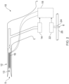
- FIG. 2 shows a cross sectional side view of the pitot tube sensing apparatus 10.
- the pitot tube sensing apparatus 10 comprises: a pitot tube 12 comprising a channel 13; a total pressure sensor 14 coupled to the channel 13; a capacitor 16; and a system 18.
- the channel 13 has a channel opening 5 which, when in use, points into an air flow.
- the air in the pitot tube 12 then stagnates as there is no substantial outlet to allow the air flow to continue.
- the total pressure sensor 14 then measures the total pressure in the pitot tube 12.
- the total pressure is the static pressure plus the dynamic pressure.
- the aircraft 1 comprises a static pressure sensor 22 to measure the static pressure of the air outside of the aircraft 1.
- the static pressure sensor 22 is connected to the outside of the aircraft 1 by a static channel 24 comprising an opening 6 through the skin 26 of the aircraft 1.
- the system 18 is in communication with the total pressure sensor 14 and the static pressure sensor 22.
- the system 18 is configured to receive the total pressure measurement from the total pressure sensor 14, and the static pressure measurement from the static pressure sensor 22.
- the system 18 is configured to calculate the airspeed based on a difference between the total pressure measurement and the static pressure measurement.
- the capacitor 16 is arranged such that if a foreign object is present in the channel 13 then the capacitance of the capacitor 16 will change.
- the system 18 is electrically connected to the capacitor 16.
- the system 18 is configured to determine the presence or absence of a foreign object within the channel 13 based on measuring a parameter indicative of a capacitance of the capacitor 16.
- Figure 3 shows a magnified view of Figure 2 . Specifically, Figure 3 shows a cross-section port-side view of the pitot tube 12 of the pitot tube sensing apparatus 10.
- the capacitor 16 comprises two electrodes 17a, 17b, on opposing sides of the channel 13. Electric field lines 31 are shown between the two electrodes 17a, 17b of the capacitor 16.
- the capacitor 16 is configured as a sensor to detect the presence or absence of a foreign object within the channel 13.
- the capacitor 16 may be adhered to the inner surface of the channel 13. Alternatively, the capacitor 16 can be integrated into the pitot tube 12.
- the capacitor 16 of the pitot tube sensing apparatus 10 may be positioned around, positioned at, or integrated into the pitot tube 12 in any way in which it can detect the presence or absence of a foreign object within the channel 13.
- the pitot tube sensing apparatus 10 comprises electrical shielding 27 between the capacitor 16 and the pitot tube 12.
- the electrical shielding 27 is arranged to insulate the two electrodes 17a, 17b from the pitot tube 12 and/or from each other.
- the electrical shielding 27 may result in a more accurate measurement from the capacitor 16.
- the electrical shielding 27 may be necessary if the pitot tube 12 is made from a conductive material which could short the two electrodes 17a, 17b together. However, if the pitot tube 12 is made of an insulating material (e.g., plastic), then electrical shielding 27 may not be necessary.
- the pitot tube sensing apparatus 10 comprises a trap 28 which is arranged to block foreign objects from reaching the pressure sensor 14.
- the capacitor 16 can be located between the opening 5 and the trap 28.
- the pitot tube sensing apparatus 10 comprises one or more drain holes 30.
- the drain holes 30 are arranged to allow liquids to drain out of the channel 13. This can prevent liquid build-up in the channel 13 from damaging (and/or blocking the channel 13) the pitot tube sensing apparatus 10, for example, when water freezes.
- the capacitor 16 is between the opening 5 and the one or more drain holes 30.
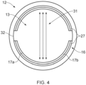
- Figure 4 shows a cross section front view of the pitot tube 12, the capacitor 16, and the electrical shielding 27. Electric field lines 31 are shown between the two electrodes 17a, 17b of the capacitor 16.
- the two electrodes 17a, 17b conform to the shape of the inner surface 32 of the channel 13.
- a benefit of the two electrodes 17a, 17b, conforming to the shape of the inner surface 32 of the channel 13 is that it maximises the detection volume of the capacitor 16 which can be used to detect foreign objects.
- the capacitor 16 is beneficially not obstructing the pitot tube 12.
- each electrode 17a, 17b is therefore in the shape of a cylindrical arc (with an arc cross-section as shown in Figure 4 ).
- Each electrode 17a, 17b can be described as conforming to the shape of the channel 13 because the channel 13 is in the shape of a cylinder and each electrode 17a, 17b is in the shape of a cylindrical arc.
- the two electrodes 17a, 17b conform to the shape of an inner surface 32 of the channel in the sense that the inner surface 32 of the channel and the inner and outer surfaces of each electrode 17a, 17b have a curved shape in a plane perpendicular to a length of the channel 13.
- system 18 is configured to measure the parameter indicative of a capacitance of the capacitor 16.
- the parameter may comprise a voltage between the two electrodes 17a, 17b.
- the system 18 can be configured to apply a current across the capacitor 16 and measure the voltage change caused by a blocking event.
- the blocking event is the event of a foreign object entering the channel 13 and getting lodged in the pitot tube 12.
- the blocking event causes a change in the permittivity of the medium between the two electrodes 17a, 17b, which results in a change in capacitance of the capacitor 16.
- the system 18 can be configured to apply a Direct Current (DC) or an Alternating Current (AC) to the capacitor 16 to detect a blocking event. In the case of DC the capacitor 16 will need to be polarized and in the case of AC the capacitor 16 will not need to be polarized.
- DC Direct Current
- AC Alternating Current
- the change in capacitance causes a change in an impedance of the capacitor 16. For a constant current if the impedance changes then the measured voltage also changes.
- Figures 5a and 5b show graphs of voltage against time, and rate of change of voltage against time respectively, for the blocking event.
- the blocking event occurs at time t1.
- Figure 5a shows the voltage received by the system 18.
- a blocking event occurs, and the voltage received by the system 18 raises as a result.
- the system 18 can determine the presence or absence of a foreign object based on a comparison of the measured parameter 35 and a detection threshold 36.
- the system 18 can determine the presence of a foreign object if the voltage raises above the detection threshold 36.
- the system 18 can determine the absence of a foreign object if the voltage does not rise above the detection threshold 36.
- the detection threshold 36 is breached shortly after t1, thus the system 18 can determine the presence of a foreign object shortly after t1.
- Figure 5b shows the rate of change of the voltage received by the system 18.
- a blocking event occurs, and the rate of change of the voltage received by the system 18 raises as a result.
- the system 18 can determine the presence or absence of a foreign objected based on a comparison of the rate of change in the parameter 37 to a detection threshold 38.
- the system 18 can determine the presence of a foreign object if the rate of change of voltage raises above the detection threshold 38.
- the system 18 can determine the absence of a foreign object if the rate of change of voltage does not raise above the detection threshold 38.
- the detection threshold 38 is breached shortly after t1, thus the system 18 can determine the presence of a foreign object shortly after t1.
- the system 18 can be configured to determine the presence or absence of a foreign object based on the voltage received and/or the rate of change of the voltage received.
- the system 18 can generate an alert upon determining the presence of a foreign object within the channel 13.
- the alert may be a warning light in the cockpit and/or an audible alarm.
- the system 18 can be one or more processing systems, controllers, computers, etc. or any combination.
- the pitot tube may be a pitot-static tube wherein the static pressure sensor opening may be integrated into the pitot tube.
- a pitot-static tube comprises a second channel co-axial with the channel of the pitot tube, wherein the second channel comprises one or more static pressure sensor openings along the sides of the pitot-static tube.
- the static pressure may be considered to be a constant for certain applications, for example in motor vehicles, boats, or other applications with an approximately constant altitude. Therefore, in an alternative example, no static pressure sensor (e.g. static pressure sensor 22) or static pressure sensor opening (e.g. static pressure sensor opening 6) may be present in the pitot tube sensing apparatus.
- no static pressure sensor e.g. static pressure sensor 22
- static pressure sensor opening e.g. static pressure sensor opening
- the pressure sensor of the pitot tube sensing apparatus may be arranged to measure the dynamic pressure (i.e. the difference between the total pressure and the static pressure).
- such pressure sensors may comprise a diaphragm between a total pressure chamber and a static pressure chamber, wherein the diaphragm position/deformation may be indicative of the dynamic pressure.
- the pressure sensor may be a manometer to provide a dynamic pressure measurement. Therefore, the system of the pitot tube sensing apparatus can be configured to determine a fluid speed based on an output of the pressure sensor, if the pressure sensor measures dynamic pressure and/or the static pressure is (or can be assumed to be) a known constant.
- the pitot tube sensing apparatus has been described for use with air, it can also be used to measure the pressure in any fluid.
- the fluid may be water when the pitot tube sensing apparatus 10 of Figure 2 is used on a boat.
- the two electrodes of the capacitor of the pitot tube sensing apparatus may be positioned in the channel between the opening of the channel and the pressure sensor.
- the capacitor may extend along the full length of the channel or a partial length of the channel.
- the pitot tube sensing apparatus may comprise one or more additional capacitors which may be applied adjacent to each other within the channel of the pitot tube and/or along each of the one or more drain holes of the pitot tube.
- the capacitor 16 is shown in Figure 3 to be between the opening 5 and the one or more drain holes 30. In an alternative example, the capacitor may be positioned between the one or more drain holes and the pressure sensor.
- the capacitor of the pitot tube sensing apparatus may not conform to the shape of the inner surface of the channel.
- the capacitor may instead be an alternative shape so long as it performs the function of detecting the presence or absence of a foreign object.
- the capacitor's two electrodes may be two parallel plates, such that the cross section of the inner surface of the channel is between the two electrodes.
- the cross section of the pitot tube may not be circular (a circular pitot tube cross section is shown in Figure 4 ).
- the pitot tube of the pitot tube sensing apparatus may be any shape which allows a channel from an opening of the channel to a pressure sensor.
- the pitot tube and/or the channel may have a substantially rectangular cross section shape.
- the capacitor may conform to the shape of the substantially rectangular cross section shape.
- the parameter indicative of a capacitance of a capacitor of the pitot tube sensing apparatus may not be voltage.
- the parameter may be current, charge, or any combination of parameters (which may include voltage).
Landscapes
- Physics & Mathematics (AREA)
- Engineering & Computer Science (AREA)
- General Physics & Mathematics (AREA)
- Aviation & Aerospace Engineering (AREA)
- Fluid Mechanics (AREA)
- Measuring Fluid Pressure (AREA)
- Remote Sensing (AREA)
- Life Sciences & Earth Sciences (AREA)
- Environmental & Geological Engineering (AREA)
- Geology (AREA)
- General Life Sciences & Earth Sciences (AREA)
- Geophysics (AREA)
- Electromagnetism (AREA)
- Investigating Or Analyzing Materials By The Use Of Electric Means (AREA)
Abstract
Description
- The present invention relates to a pitot tube sensing apparatus and a method of determining the presence or absence of a foreign object within the pitot tube sensing apparatus. In particular, the pitot tube sensing apparatus is suitable for use with an aircraft.
- A pitot tube sensing apparatus typically comprises a pitot tube coupled to a pressure sensor. A pitot tube sensing apparatus may be used to measure pressure to determine fluid flow speed.
- Pitot tube sensing apparatus is widely used to determine the airspeed of an aircraft; the water speed of a boat; or the flow velocity of liquids, air, and gases in industry. A generic prior art pitot tube sensing apparatus comprises a pitot tube directly coupled to a pressure sensor. The pitot tube is arranged with an opening which points directly into a fluid flow, the fluid then stagnates in the pitot tube as there is no outlet to allow the flow to continue. The pressure sensor then measures the total pressure in the pitot tube.
- The total pressure can be described as the static pressure plus the dynamic pressure. The speed of the fluid can be calculated from the dynamic pressure. For many applications the static pressure is a pre-defined and known pressure. However, the static pressure can vary for aircraft when changing altitude. In such applications where the static pressure is not pre-defined or known, a static pressure sensor can be added to the pitot tube sensing apparatus to measure the static pressure.
- A pitot tube comprises a channel which can be blocked by foreign objects such as ice, dust, dirt, sand, insects, protective covers, and other debris. This can lead to an erroneous pressure measurement at the pressure sensor.
- A pitot tube sensing apparatus is typically used with aircraft as a primary source of total pressure to determine airspeed. Before take-off, the pitot tube should ideally be clear of foreign objects.
- There is therefore a desire to ensure that a pitot tube is clear of foreign objects.
- A first aspect of the invention provides a pitot tube sensing apparatus comprising: a pitot tube comprising a channel; a pressure sensor coupled to the channel; a capacitor comprising two electrodes on opposing sides of the channel; and a system configured to: measure a parameter indicative of a capacitance between the two electrodes; and determine the presence or absence of a foreign object within the channel based on the parameter.
- The pitot tube sensing apparatus may comprise electrical shielding between the capacitor and the pitot tube.
- The parameter may comprise a voltage between the two electrodes.
- Optionally the system is configured to measure the parameter by applying current across the capacitor.
- The determination of the presence or absence of a foreign object may be based on a comparison of the parameter to a detection threshold.
- The system may be further configured to calculate a rate of change in the parameter. The determination of the presence or absence of a foreign object may be based on a comparison of the rate of change in the parameter to a detection threshold. Advantageously, this determination may result in a more reliable determination of a foreign object.
- The two electrodes may conform to the shape of an inner surface of the channel.
- The inner surface of the channel may have a curved shape in a plane perpendicular to a length of the channel. Each electrode may also have an inner or outer surface with a curved shape in the plane. Advantageously, electrodes conforming to the inner surface preserves the cross-sectional shape of the flow passage, and may also improve pressure reading accuracy.
- The channel may be in the shape of a cylinder. Each electrode may be in the shape of a cylindrical arc.
- The pitot tube sensing apparatus may further comprise a trap. The capacitor may be between an opening of the channel and the trap. The trap may be arranged to block foreign objects from reaching the pressure sensor.
- The pitot tube sensing apparatus may be further configured to generate an alert upon determining the presence of a foreign object within the channel.
- The pitot tube sensing apparatus may be configured to determine a fluid speed based on an output of the pressure sensor.
- The electrodes may be positioned in the channel between an opening of the channel and the pressure sensor.
- The pressure sensor may be configured to measure a total pressure in the channel. The pitot tube sensing apparatus may further comprise a static pressure sensor configured to measure a static pressure. The pitot tube sensing apparatus may be further configured to calculate a fluid speed based on a difference between the total pressure and the static pressure.
- A further aspect of the invention provides an aircraft comprising the pitot tube sensing apparatus of the first aspect.
- The pitot tube sensing apparatus may be configured to determine an air speed of the aircraft based on an output of the pressure sensor.
- A further aspect of the invention provides a method of determining the presence or absence of a foreign object within a pitot tube sensing apparatus, wherein the pitot tube sensing apparatus comprises: a pitot tube comprising a channel with an opening; a pressure sensor coupled to the channel; and a capacitor comprising two electrodes on opposing sides of the channel, the method comprising: measuring a parameter indicative of a capacitance between the two electrodes; and determining the presence or absence of a foreign object within the channel based on the parameter.
- The two electrodes may conform to the shape of an inner surface of the channel.
- The parameter may comprise a voltage between the two electrodes.
- Determining the presence or absence of a foreign object may be based on a comparison of the parameter to a detection threshold.
- The method may further comprise calculating a rate of change in the parameter. The determination of the presence or absence of a foreign object may be based on a comparison of the rate of change in the parameter to a detection threshold.
- The method may further comprise generating an alert upon determining the presence of a foreign object within the channel.
- Embodiments of the invention will now be described with reference to the accompanying drawings, in which:
-
Figure 1a shows a front view of an aircraft; -
Figure 1b shows a port-side view of the front portion of the aircraft ofFigure 1a ; -
Figure 2 shows a cross section port-side view of a pitot tube sensing apparatus; -
Figure 3 shows a cross section port-side view of a pitot tube of the pitot tube sensing apparatus ofFigure 2 ; -
Figure 4 shows a cross section front view of a pitot tube of the pitot tube sensing apparatus ofFigure 2 ; -
Figure 5a shows a graph of voltage against time; and -
Figure 5b shows a graph of rate of change in voltage against time. - Like reference numerals refer to like parts throughout the specification. With reference to
Figures 1a and 1b , apassenger aircraft 1 is shown. Theaircraft 1 comprises a fuselage 2 for holding passengers and/or cargo, astarboard wing 3 and a port wing 4. -
Figure 1b shows a port-side view of the front portion of thepassenger aircraft 1. Apitot tube opening 5 of a pitottube sensing apparatus 10 is positioned such that when theaircraft 1 is in flight a pressure sensor of the pitottube sensing apparatus 10 is arranged to measure the total pressure. For example, the axis of the pitot tube can be approximately in the same direction as the direction of travel of theaircraft 1. - A static
pressure sensor opening 6 of a static pressure sensor is positioned such that when theaircraft 1 is in flight the static pressure sensor is arranged to measure the static pressure. For example, the axis of the static pressure sensor can be approximately perpendicular to the axis of the pitot tube. -
Figure 2 shows a cross sectional side view of the pitottube sensing apparatus 10. The pitottube sensing apparatus 10 comprises: apitot tube 12 comprising achannel 13; atotal pressure sensor 14 coupled to thechannel 13; acapacitor 16; and asystem 18. - The
channel 13 has achannel opening 5 which, when in use, points into an air flow. The air in thepitot tube 12 then stagnates as there is no substantial outlet to allow the air flow to continue. Thetotal pressure sensor 14 then measures the total pressure in thepitot tube 12. - The total pressure is the static pressure plus the dynamic pressure. The
aircraft 1 comprises a static pressure sensor 22 to measure the static pressure of the air outside of theaircraft 1. The static pressure sensor 22 is connected to the outside of theaircraft 1 by astatic channel 24 comprising anopening 6 through theskin 26 of theaircraft 1. - The
system 18 is in communication with thetotal pressure sensor 14 and the static pressure sensor 22. Thesystem 18 is configured to receive the total pressure measurement from thetotal pressure sensor 14, and the static pressure measurement from the static pressure sensor 22. Thesystem 18 is configured to calculate the airspeed based on a difference between the total pressure measurement and the static pressure measurement. - The
capacitor 16 is arranged such that if a foreign object is present in thechannel 13 then the capacitance of thecapacitor 16 will change. - The
system 18 is electrically connected to thecapacitor 16. Thesystem 18 is configured to determine the presence or absence of a foreign object within thechannel 13 based on measuring a parameter indicative of a capacitance of thecapacitor 16. -
Figure 3 shows a magnified view ofFigure 2 . Specifically,Figure 3 shows a cross-section port-side view of thepitot tube 12 of the pitottube sensing apparatus 10. - The
capacitor 16 comprises twoelectrodes channel 13. Electric field lines 31 are shown between the twoelectrodes capacitor 16. The capacitance of thecapacitor 16 is:
- A is the effective overlap area of the two
electrodes - d is the effective distance between the two
electrodes - ε is the permittivity of the medium between the two
electrodes - When the channel is clear of foreign objects then ε is relatively stable, since the permittivity of air is relatively stable. However, when a foreign object enters the
channel 13 then ε changes, such that a change in capacitance of thecapacitor 16 can be detected either directly or indirectly by thesystem 18. Therefore, thecapacitor 16 is configured as a sensor to detect the presence or absence of a foreign object within thechannel 13. - The
capacitor 16 may be adhered to the inner surface of thechannel 13. Alternatively, thecapacitor 16 can be integrated into thepitot tube 12. Thecapacitor 16 of the pitottube sensing apparatus 10 may be positioned around, positioned at, or integrated into thepitot tube 12 in any way in which it can detect the presence or absence of a foreign object within thechannel 13. - The pitot
tube sensing apparatus 10 comprises electrical shielding 27 between thecapacitor 16 and thepitot tube 12. Theelectrical shielding 27 is arranged to insulate the twoelectrodes pitot tube 12 and/or from each other. Theelectrical shielding 27 may result in a more accurate measurement from thecapacitor 16. Theelectrical shielding 27 may be necessary if thepitot tube 12 is made from a conductive material which could short the twoelectrodes pitot tube 12 is made of an insulating material (e.g., plastic), then electrical shielding 27 may not be necessary. - Optionally the pitot
tube sensing apparatus 10 comprises atrap 28 which is arranged to block foreign objects from reaching thepressure sensor 14. Thecapacitor 16 can be located between theopening 5 and thetrap 28. - Optionally the pitot
tube sensing apparatus 10 comprises one or more drain holes 30. The drain holes 30 are arranged to allow liquids to drain out of thechannel 13. This can prevent liquid build-up in thechannel 13 from damaging (and/or blocking the channel 13) the pitottube sensing apparatus 10, for example, when water freezes. Thecapacitor 16 is between theopening 5 and the one or more drain holes 30. -
Figure 4 shows a cross section front view of thepitot tube 12, thecapacitor 16, and theelectrical shielding 27. Electric field lines 31 are shown between the twoelectrodes capacitor 16. - The two
electrodes inner surface 32 of thechannel 13. A benefit of the twoelectrodes inner surface 32 of thechannel 13 is that it maximises the detection volume of thecapacitor 16 which can be used to detect foreign objects. In addition, thecapacitor 16 is beneficially not obstructing thepitot tube 12. - As shown in
Figure 4 , the cross section of thepitot tube 12 is circular because thepitot tube 12 and itschannel 13 are cylindrical. Eachelectrode Figure 4 ). Eachelectrode channel 13 because thechannel 13 is in the shape of a cylinder and eachelectrode electrodes inner surface 32 of the channel in the sense that theinner surface 32 of the channel and the inner and outer surfaces of eachelectrode channel 13. - Turning to the functionality of the pitot
tube sensing apparatus 10,system 18 is configured to measure the parameter indicative of a capacitance of thecapacitor 16. The parameter may comprise a voltage between the twoelectrodes - The
system 18 can be configured to apply a current across thecapacitor 16 and measure the voltage change caused by a blocking event. The blocking event is the event of a foreign object entering thechannel 13 and getting lodged in thepitot tube 12. The blocking event causes a change in the permittivity of the medium between the twoelectrodes capacitor 16. Thesystem 18 can be configured to apply a Direct Current (DC) or an Alternating Current (AC) to thecapacitor 16 to detect a blocking event. In the case of DC thecapacitor 16 will need to be polarized and in the case of AC thecapacitor 16 will not need to be polarized. - The change in capacitance causes a change in an impedance of the
capacitor 16. For a constant current if the impedance changes then the measured voltage also changes. -
Figures 5a and 5b show graphs of voltage against time, and rate of change of voltage against time respectively, for the blocking event. The blocking event occurs at time t1. -
Figure 5a shows the voltage received by thesystem 18. At time t1, a blocking event occurs, and the voltage received by thesystem 18 raises as a result. Thesystem 18 can determine the presence or absence of a foreign object based on a comparison of the measuredparameter 35 and adetection threshold 36. Thesystem 18 can determine the presence of a foreign object if the voltage raises above thedetection threshold 36. Thesystem 18 can determine the absence of a foreign object if the voltage does not rise above thedetection threshold 36. As shown inFigure 5a , thedetection threshold 36 is breached shortly after t1, thus thesystem 18 can determine the presence of a foreign object shortly after t1. -
Figure 5b shows the rate of change of the voltage received by thesystem 18. At time t1, a blocking event occurs, and the rate of change of the voltage received by thesystem 18 raises as a result. Thesystem 18 can determine the presence or absence of a foreign objected based on a comparison of the rate of change in theparameter 37 to adetection threshold 38. Thesystem 18 can determine the presence of a foreign object if the rate of change of voltage raises above thedetection threshold 38. Thesystem 18 can determine the absence of a foreign object if the rate of change of voltage does not raise above thedetection threshold 38. InFigure 5b , thedetection threshold 38 is breached shortly after t1, thus thesystem 18 can determine the presence of a foreign object shortly after t1. - The
system 18 can be configured to determine the presence or absence of a foreign object based on the voltage received and/or the rate of change of the voltage received. - The
system 18 can generate an alert upon determining the presence of a foreign object within thechannel 13. For example, in theaircraft 1, the alert may be a warning light in the cockpit and/or an audible alarm. - The
system 18 can be one or more processing systems, controllers, computers, etc. or any combination. - In an alternative example, the pitot tube may be a pitot-static tube wherein the static pressure sensor opening may be integrated into the pitot tube. A pitot-static tube comprises a second channel co-axial with the channel of the pitot tube, wherein the second channel comprises one or more static pressure sensor openings along the sides of the pitot-static tube.
- The static pressure may be considered to be a constant for certain applications, for example in motor vehicles, boats, or other applications with an approximately constant altitude. Therefore, in an alternative example, no static pressure sensor (e.g. static pressure sensor 22) or static pressure sensor opening (e.g. static pressure sensor opening 6) may be present in the pitot tube sensing apparatus.
- The pressure sensor of the pitot tube sensing apparatus may be arranged to measure the dynamic pressure (i.e. the difference between the total pressure and the static pressure). For example, such pressure sensors may comprise a diaphragm between a total pressure chamber and a static pressure chamber, wherein the diaphragm position/deformation may be indicative of the dynamic pressure. In another example, the pressure sensor may be a manometer to provide a dynamic pressure measurement. Therefore, the system of the pitot tube sensing apparatus can be configured to determine a fluid speed based on an output of the pressure sensor, if the pressure sensor measures dynamic pressure and/or the static pressure is (or can be assumed to be) a known constant.
- Although the pitot tube sensing apparatus has been described for use with air, it can also be used to measure the pressure in any fluid. For example, the fluid may be water when the pitot
tube sensing apparatus 10 ofFigure 2 is used on a boat. - The two electrodes of the capacitor of the pitot tube sensing apparatus may be positioned in the channel between the opening of the channel and the pressure sensor. The capacitor may extend along the full length of the channel or a partial length of the channel.
- The pitot tube sensing apparatus may comprise one or more additional capacitors which may be applied adjacent to each other within the channel of the pitot tube and/or along each of the one or more drain holes of the pitot tube.
- The
capacitor 16 is shown inFigure 3 to be between theopening 5 and the one or more drain holes 30. In an alternative example, the capacitor may be positioned between the one or more drain holes and the pressure sensor. - The capacitor of the pitot tube sensing apparatus may not conform to the shape of the inner surface of the channel. The capacitor may instead be an alternative shape so long as it performs the function of detecting the presence or absence of a foreign object. For example, the capacitor's two electrodes may be two parallel plates, such that the cross section of the inner surface of the channel is between the two electrodes.
- In an alternative example, the cross section of the pitot tube may not be circular (a circular pitot tube cross section is shown in
Figure 4 ). The pitot tube of the pitot tube sensing apparatus may be any shape which allows a channel from an opening of the channel to a pressure sensor. For example, the pitot tube and/or the channel may have a substantially rectangular cross section shape. The capacitor may conform to the shape of the substantially rectangular cross section shape. - In an alternative example, the parameter indicative of a capacitance of a capacitor of the pitot tube sensing apparatus may not be voltage. For example, the parameter may be current, charge, or any combination of parameters (which may include voltage).
- Where the word 'or' appears this is to be construed to mean 'and/or' such that items referred to are not necessarily mutually exclusive and may be used in any appropriate combination.
- Although the invention has been described above with reference to one or more preferred embodiments, it will be appreciated that various changes or modifications may be made without departing from the scope of the invention as defined in the appended claims.
Claims (15)
- A pitot tube sensing apparatus comprising:a pitot tube comprising a channel;a pressure sensor coupled to the channel;a capacitor comprising two electrodes on opposing sides of the channel, whereinthe two electrodes conform to the shape of an inner surface of the channel; anda system configured to:measure a parameter indicative of a capacitance between the two electrodes; anddetermine the presence or absence of a foreign object within the channel based on the parameter.
- The pitot tube sensing apparatus of claim 1, wherein the parameter comprises a voltage between the two electrodes.
- The pitot tube sensing apparatus of any preceding claim, wherein the determination of the presence or absence of a foreign object is based on a comparison of the parameter to a detection threshold.
- The pitot tube sensing apparatus of any preceding claim, wherein the system is further configured to calculate a rate of change in the parameter, wherein the determination of the presence or absence of a foreign object is based on a comparison of the rate of change in the parameter to a detection threshold.
- The pitot tube sensing apparatus of any preceding claim, wherein the inner surface of the channel and an inner surface of each electrode have a curved shape in a plane perpendicular to a length of the channel..
- The pitot tube sensing apparatus of any preceding claim, wherein the channel is in the shape of a cylinder, and each electrode is in the shape of a cylindrical arc.
- The pitot tube sensing apparatus of any preceding claim, wherein the pitot tube sensing apparatus further comprises a trap, the capacitor is between an opening of the channel and the trap, and the trap is arranged to block foreign objects from reaching the pressure sensor.
- The pitot tube sensing apparatus of any preceding claim, wherein the pitot tube sensing apparatus is further configured to generate an alert upon determining the presence of a foreign object within the channel.
- The pitot tube sensing apparatus of any preceding claim, wherein the pitot tube sensing apparatus is configured to determine a fluid speed based on an output of the pressure sensor.
- An aircraft comprising the pitot tube sensing apparatus of any preceding claim.
- An aircraft according to claim 10, wherein the pitot tube sensing apparatus is configured to determine an air speed of the aircraft based on an output of the pressure sensor.
- A method of determining the presence or absence of a foreign object within a pitot tube sensing apparatus, wherein the pitot tube sensing apparatus comprises:a pitot tube comprising a channel with an opening;a pressure sensor coupled to the channel; anda capacitor comprising two electrodes on opposing sides of the channel, wherein the two electrodes conform to the shape of an inner surface of the channel,
the method comprising:measuring a parameter indicative of a capacitance between the two electrodes; anddetermining the presence or absence of a foreign object within the channel based on the parameter. - The method of claim 12, wherein determining the presence or absence of a foreign object is based on a comparison of the parameter to a detection threshold.
- The method of any of claims 12 or 13, further comprising calculating a rate of change in the parameter, wherein the determination of the presence or absence of a foreign object is based on a comparison of the rate of change in the parameter to a detection threshold.
- The method of any of claims 12 to 14, further comprising generating an alert upon determining the presence of a foreign object within the channel.
Applications Claiming Priority (1)
| Application Number | Priority Date | Filing Date | Title |
|---|---|---|---|
| IN202211035631 | 2022-06-21 |
Publications (2)
| Publication Number | Publication Date |
|---|---|
| EP4296689A1 true EP4296689A1 (en) | 2023-12-27 |
| EP4296689B1 EP4296689B1 (en) | 2026-01-21 |
Family
ID=86776256
Family Applications (1)
| Application Number | Title | Priority Date | Filing Date |
|---|---|---|---|
| EP23179220.1A Active EP4296689B1 (en) | 2022-06-21 | 2023-06-14 | A pitot tube sensing apparatus |
Country Status (2)
| Country | Link |
|---|---|
| US (1) | US12442831B2 (en) |
| EP (1) | EP4296689B1 (en) |
Families Citing this family (2)
| Publication number | Priority date | Publication date | Assignee | Title |
|---|---|---|---|---|
| US12480970B1 (en) * | 2022-03-29 | 2025-11-25 | Nav-Aids Ltd | Pitot-static test adapter |
| CN121047834B (en) * | 2025-10-31 | 2026-01-30 | 苏州元脑智能科技有限公司 | Fan control method, electronic device, storage medium, and program product |
Citations (4)
| Publication number | Priority date | Publication date | Assignee | Title |
|---|---|---|---|---|
| US5191791A (en) * | 1989-01-10 | 1993-03-09 | Gerardi Joseph J | Piezoelectric sensor |
| EP0781705A2 (en) * | 1995-12-22 | 1997-07-02 | The B.F. Goodrich Company | Impedance type ice detector |
| WO2009000244A1 (en) * | 2007-06-27 | 2008-12-31 | Mtu Aero Engines Gmbh | Detection device for detecting ice deposits on gas turbine components and a gas turbine comprising said type of detection device |
| US11203438B1 (en) * | 2018-12-13 | 2021-12-21 | Rockwell Collins, Inc. | System and method for deicing |
Family Cites Families (12)
| Publication number | Priority date | Publication date | Assignee | Title |
|---|---|---|---|---|
| US5438880A (en) | 1994-05-17 | 1995-08-08 | United Technologies Corporation | Electrostatic linear airspeed transducer |
| US6205376B1 (en) * | 1999-06-22 | 2001-03-20 | Rockwell Collins, Inc. | Blocked pitot-static monitor |
| US8060334B1 (en) | 2010-09-03 | 2011-11-15 | Philip Onni Jarvinen | Aircraft pitot-static tube with ice detection |
| US9322685B2 (en) | 2014-06-30 | 2016-04-26 | The Boeing Company | MEMS-based conformal air speed sensor |
| EP3112819B1 (en) | 2015-06-30 | 2020-03-11 | Commissariat A L'energie Atomique Et Aux Energies Alternatives | Miniature differential pressure flow sensor |
| US10155373B2 (en) | 2015-10-16 | 2018-12-18 | Quest Integrated, Llc | Printed multifunctional skin for aerodynamic structures, and associated systems and methods |
| US10126320B2 (en) * | 2017-03-13 | 2018-11-13 | Honeywell International Inc. | Arrangement of dams in air data probe |
| US11035877B2 (en) * | 2018-09-12 | 2021-06-15 | Bell Helicopter Textron Inc. | Pitot-static system blockage detector |
| EP3738882B1 (en) | 2019-05-14 | 2024-04-03 | Airbus Operations, S.L. | Aerodynamics improvement device for an aircraft and aircraft equipped with such device |
| US11237031B2 (en) | 2019-08-20 | 2022-02-01 | Rosemount Aerospace Inc. | Additively manufactured heaters for air data probes having a heater layer and a dielectric layer on the air data probe body |
| EP4034888A4 (en) | 2019-09-26 | 2023-11-01 | Aerosonic LLC | Aircraft airflow sensor having a vane with integrated pressure transducers |
| US11332260B2 (en) | 2019-11-18 | 2022-05-17 | The Boeing Company | Electrode-arc sensor air data system for an aircraft |
-
2023
- 2023-06-14 EP EP23179220.1A patent/EP4296689B1/en active Active
- 2023-06-20 US US18/338,067 patent/US12442831B2/en active Active
Patent Citations (4)
| Publication number | Priority date | Publication date | Assignee | Title |
|---|---|---|---|---|
| US5191791A (en) * | 1989-01-10 | 1993-03-09 | Gerardi Joseph J | Piezoelectric sensor |
| EP0781705A2 (en) * | 1995-12-22 | 1997-07-02 | The B.F. Goodrich Company | Impedance type ice detector |
| WO2009000244A1 (en) * | 2007-06-27 | 2008-12-31 | Mtu Aero Engines Gmbh | Detection device for detecting ice deposits on gas turbine components and a gas turbine comprising said type of detection device |
| US11203438B1 (en) * | 2018-12-13 | 2021-12-21 | Rockwell Collins, Inc. | System and method for deicing |
Also Published As
| Publication number | Publication date |
|---|---|
| US12442831B2 (en) | 2025-10-14 |
| US20230408720A1 (en) | 2023-12-21 |
| EP4296689B1 (en) | 2026-01-21 |
Similar Documents
| Publication | Publication Date | Title |
|---|---|---|
| US12442831B2 (en) | Pitot tube sensing apparatus | |
| US4766369A (en) | Ice detector | |
| US8184290B2 (en) | Device and method for monitoring the particle contamination in flowing hydraulic fluids | |
| US10422680B2 (en) | Method for monitoring at least one media-specific property of a medium | |
| CN102466535B (en) | For detecting the system and method for the Pi Tuo-static port of blocking | |
| US9366555B2 (en) | Air data system | |
| EP3739343B1 (en) | Air data system architectures including laser air data and acoustic air data sensors | |
| JP7324035B2 (en) | Systems and methods for deriving airspeed from particle sensors | |
| US10527640B2 (en) | System and method for pitot tube blockage detection | |
| CN106556439B (en) | Entrained flow detection diagnostics | |
| WO2015071170A1 (en) | Vehicle having wade sensing display and system therefor | |
| EP4524522A3 (en) | Fluid detection system | |
| GB2621347A (en) | A pitot tube sensing apparatus | |
| JP2001194211A (en) | Method and apparatus for decision of limit filling level of object, to be filled, at inside of container | |
| EP3822642B1 (en) | Air data system for an aircraft | |
| US10401160B2 (en) | Method for determining the layer thickness of a connecting layer between two packaging layers | |
| KR20160013682A (en) | Apparatus and method for detecting flaw of tire | |
| US3147169A (en) | Apparatus for determining thickness during chemical milling | |
| CN118265894A (en) | Method for detecting foreign matter in a medium | |
| US20190390986A1 (en) | Vortex flowmeter with flow instability detection | |
| EP3665470A1 (en) | Collision avoidance for particle beam instruments | |
| CN109901171B (en) | Automobile rear-end collision prevention early warning method | |
| Happel et al. | Capacitive sensors for contactless level and composition measurement in automotive clear vision systems | |
| US12112648B2 (en) | Determining vehicle operating state by particle detection | |
| EP4019901B1 (en) | Vehicle sensor system including barometric pressure sensors |
Legal Events
| Date | Code | Title | Description |
|---|---|---|---|
| PUAI | Public reference made under article 153(3) epc to a published international application that has entered the european phase |
Free format text: ORIGINAL CODE: 0009012 |
|
| STAA | Information on the status of an ep patent application or granted ep patent |
Free format text: STATUS: THE APPLICATION HAS BEEN PUBLISHED |
|
| AK | Designated contracting states |
Kind code of ref document: A1 Designated state(s): AL AT BE BG CH CY CZ DE DK EE ES FI FR GB GR HR HU IE IS IT LI LT LU LV MC ME MK MT NL NO PL PT RO RS SE SI SK SM TR |
|
| STAA | Information on the status of an ep patent application or granted ep patent |
Free format text: STATUS: REQUEST FOR EXAMINATION WAS MADE |
|
| 17P | Request for examination filed |
Effective date: 20240626 |
|
| RBV | Designated contracting states (corrected) |
Designated state(s): AL AT BE BG CH CY CZ DE DK EE ES FI FR GB GR HR HU IE IS IT LI LT LU LV MC ME MK MT NL NO PL PT RO RS SE SI SK SM TR |
|
| GRAP | Despatch of communication of intention to grant a patent |
Free format text: ORIGINAL CODE: EPIDOSNIGR1 |
|
| STAA | Information on the status of an ep patent application or granted ep patent |
Free format text: STATUS: GRANT OF PATENT IS INTENDED |
|
| RIC1 | Information provided on ipc code assigned before grant |
Ipc: G01P 5/165 20060101AFI20250827BHEP Ipc: B64D 15/20 20060101ALI20250827BHEP Ipc: B64D 43/02 20060101ALI20250827BHEP Ipc: G01F 1/46 20060101ALI20250827BHEP Ipc: G01F 15/063 20220101ALI20250827BHEP Ipc: G01P 13/02 20060101ALN20250827BHEP |
|
| RIC1 | Information provided on ipc code assigned before grant |
Ipc: G01P 5/165 20060101AFI20250904BHEP Ipc: B64D 15/20 20060101ALI20250904BHEP Ipc: B64D 43/02 20060101ALI20250904BHEP Ipc: G01F 1/46 20060101ALI20250904BHEP Ipc: G01F 15/063 20220101ALI20250904BHEP Ipc: G01P 13/02 20060101ALN20250904BHEP |
|
| INTG | Intention to grant announced |
Effective date: 20250912 |
|
| GRAS | Grant fee paid |
Free format text: ORIGINAL CODE: EPIDOSNIGR3 |
|
| GRAA | (expected) grant |
Free format text: ORIGINAL CODE: 0009210 |
|
| STAA | Information on the status of an ep patent application or granted ep patent |
Free format text: STATUS: THE PATENT HAS BEEN GRANTED |
|
| AK | Designated contracting states |
Kind code of ref document: B1 Designated state(s): AL AT BE BG CH CY CZ DE DK EE ES FI FR GB GR HR HU IE IS IT LI LT LU LV MC ME MK MT NL NO PL PT RO RS SE SI SK SM TR |
|
| REG | Reference to a national code |
Ref country code: CH Ref legal event code: F10 Free format text: ST27 STATUS EVENT CODE: U-0-0-F10-F00 (AS PROVIDED BY THE NATIONAL OFFICE) Effective date: 20260121 |
|
| REG | Reference to a national code |
Ref country code: DE Ref legal event code: R096 Ref document number: 602023010913 Country of ref document: DE |
|
| REG | Reference to a national code |
Ref country code: IE Ref legal event code: FG4D |